

Page 1

Document Name:
MBSC0700-040-RUXX
MBSC0700-020-RUXX
Revision:
Effective Date:
001.02A
12/15/2015
USER MANUAL
Fiber Optic MBSC Platform
MBSC0700-040-RUXX
MBSC0700-020-RUXX
High-Power In-Building
6185 Phyllis Drive
Cypress, CA 90630
USA
PH: 714.230.8333
Coverage Solution
Visit our Website at www.BTIwireless.com
Page 2

Website: www.btiwireless.com
Copyright © 2016 BTI Wireless All rights reserved.
No part of this publication may be reproduced, transmitted, transcribed, stored in a retrieval system, or translated into
any language, in any form or by any means, electronic, mechanical, photocopying, recording, or otherwise, without
prior written permission from BTI Wireless.
All copyright, confidential information, patents, design rights and all other intellectual property rights of whatsoever
nature contained herein are and shall remain the sole and exclusive property of BTI Wireless. The information
furnished herein is believed to be accurate and reliable.
However, no responsibility is assumed by BTI Wireless for its use, or for any infringements of patents or other rights of
third parties resulting from its use.
The BTI Wireless name and BTI Wireless logo are trademarks or registered trademarks of BTI Wireless
MBSC-C RU
All other trademarks are the property of their respective owners
BTI Wireless
6185 Phyllis Drive Unit D, Cypress, CA 90630
Phone: 1-714-230-8333
MBSC-C
Page 3
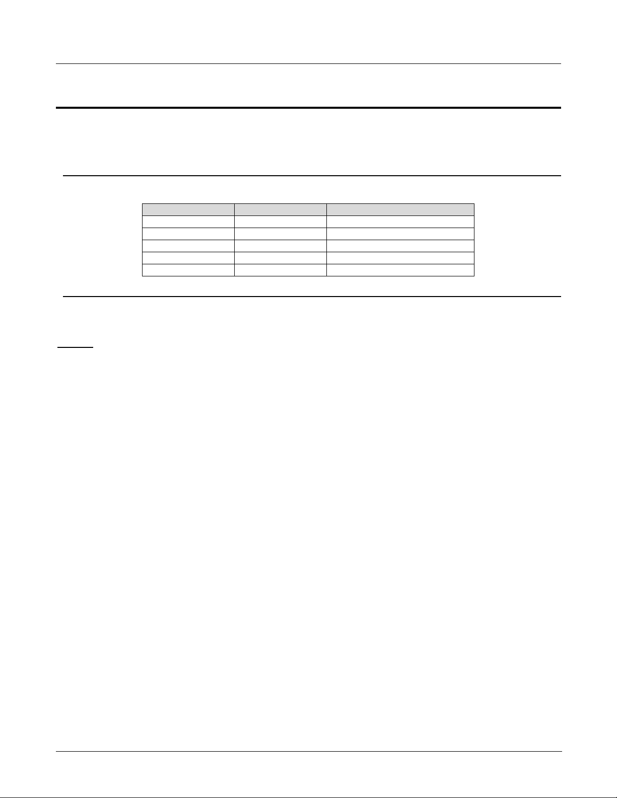
MBSC-C RU
Revision Number
Revision Date
Summary of Changes
001.00A
2/28/2013
Initial Release for NA
001.01A
4/15/2013
Updated for new EMS
001.02A
12/15/2015
Added new modules
Document History
Paper copies are valid only on the day they are printed. Contact the author if you are in any doubt about the
accuracy of this document.
Revision History
GENERAL SAFETY PRECAUTIONS
Warning: Wet conditions increase the potential for receivi ng an electric al shock when installing or using electrically-powered
equipment. To prevent electrical shock, never install or use electrical equipment in a wet location or during a lighting stor m.
Improper installation and operation of this equipment outside of the recommended installation procedures, and operation
beyond the designed operating specifications, and/or not in compliance with regulatory requirements, will revoke any warranty
and may:
Prevent the equipment from perform i ng properly
Violate regulatory RF emissions requirements
Require removal of the equipment f rom service.
©2015-2016 BTI Wireless Inc.
Page 4

MBSC-C RU
TABLE OF CONTENTS
1 INTRODUCTION 1
1.1 SYSTEM SOLUTION BLOCK DIAGRAM 1
1.1.1 Host Unit 1
1.1.2 Remote Node 2
2 SAFETY 3
3 SYSTEM OVERVIEW AND UNIT DESCRIPTION 4
3.1 SYSTEM OVERVIEW 4
3.1.1 Interface with BTS 4
3.1.2 Interface with Cellular Phones 5
3.1.3 Fiber Optic T ransp ort 5
3.1.4 Powering 5
3.1.5 Cooling 5
3.1.6 Fault Detection and Alarm Reporting 5
3.2 HOST UNIT DESCRIPTION 5
3.2.1 Host Unit Components 6
3.2.2 Mounting 9
3.2.3 Fault Detection and Alarm Reporting 9
3.2.4 RF Signal Connections 9
3.2.5 Optical Connections 9
3.2.6 Powering 10
3.2.7 Host Unit Interface 10
3.3 REMOTE NODE DESCRIPTION 12
3.3.1 CM-BTS/ANT Encl osure 12
3.3.2 Single-band RUEnclosure 17
3.3.3 Power Supply Junction Box 20
3.3.4 Shroud& Bracket 21
4 SYSTEM INSTALLATION 23
4.1 UNP ACKING AND INSPECTION 23
4.2 INSTALLATION PREPARATION 23
4.2.1 Required Tools 23
4.2.2 Installation Location 23
4.2.3 Anti-corrosion an d S hoc k-protection 24
4.2.4 Lighting, Ventilation and Fire Protection 24
4.2.5 Power Requirements 24
©2015-2016 BTI Wireless Inc.
Page 5

MBSC-C RU
4.2.6 Lightning Protecting and Grounding 24
4.3 HOST UNIT INSTALLATION 24
4.3.1 Rack Mounting 24
4.3.2 Cable Connections 26
4.4 REMOTE NODE INSTALLATION 30
4.4.1 Bracket and Shroud Installation 30
4.4.2 Cable Connections 33
4.5 INSTALLATION FINAL INSPECTION 38
4.5.1 Host Unit Connection Overview 39
4.5.2 Remote Node Connection Overview 40
4.5.3 mBSC-C Inspection Checklist 41
4.5.4 Cabling Inspection 41
4.6 SYSTEM TEST 41
5 SYSTEM MONITORING &CONFIGURATION 43
5.1 ACCESSING EMS LOCAL GUI 43
5.1.1 Using Ethernet Port 43
5.1.2 Using USB Port 44
5.1.3 Login to EMS Local GUI 45
5.2 NAVIGATING THE EMS LOCAL GUI 46
5.2.1 T opology Tool Bar 47
5.2.2 Upgrade/Password Functions 48
5.3 INSTALLATION & CONFIGURATION 48
5.3.1 Network & Communications 48
5.3.2 System Installation 50
5.3.3 Alarms 55
5.4 SYSTEM TUNING 57
5.4.1 BTS Signal Conditioning 57
5.4.2 Set Downlink Gain 57
5.4.3 Set Uplink Gain 60
5.4.4 Link Verification 62
5.5 MONITORING AND ALARMS 64
5.5.1 Operational Status 64
5.5.2 System Alarms 66
5.6 SYSTEM UPGRADE 67
5.6.1 Verify Software Versions 67
5.6.2 Upgrade component software 67
©2015-2016 BTI Wireless Inc.
Page 6

MBSC-C RU
6 MAINTENANCE 68
6.1 ELECTROSTATIC DISCHARGE PRECAUTIONS 68
6.2 PREVENTATIVE MAINTENANCE 68
6.3 FAULT DETECTION AND ALARM REPORTING 68
6.4 TROUBLESHOOTING QUICK GUIDE 69
6.4.1 Host Unit Tro uble Shooting 70
6.4.2 Remote Unit T rouble Shooting 71
7 TERMS, ACRONYMS & ABBREVIATIONS 72
8 PACKING LIST 73
©2015-2016 BTI Wireless Inc.
Page 7

MBSC-C RU
LIST OF FIGURES
FIGURE 1BLOCK DIAGRAM OF HOST UNIT ................................................................................................................................. 1
FIGURE 2 BLOCK DIAGRAM OF REMOTE NODE .......................................................................................................................... 2
FIGURE 3MBSC SYSTEM FUNCTIONAL OVERVIEW ..................................................................................................................... 4
FIGURE 4 HOST UNIT .................................................................................................................................................................. 6
FIGURE 5BIU ............................................................................................................................................................................. 7
FIGURE 6FIU .............................................................................................................................................................................. 7
FIGURE 7 PSU ............................................................................................................................................................................ 8
FIGURE 8RCU ............................................................................................................................................................................ 9
FIGURE 9 HOST UNIT USER INTERFACE .................................................................................................................................... 11
FIGURE 10FIBER CM-BTS/ANT ENCLOSURE OUTLINE ........................................................................................................... 13
FIGURE 11FIBER CM-BTS/ANT INTERIOR LAYOUT ................................................................................................................ 14
FIGURE 12FIBER CM-BTS/ANT ENCLOSURE USER INTERFACE .............................................................................................. 17
FIGURE 13SINGLE-BAND RU ENCLOSURE ................................................................................................................................ 18
FIGURE 14 SINGLE-BAND RU ENCLOSURE USER INTERFACE ................................................................................................... 20
FIGURE 15POWER BOX OUTLINE .............................................................................................................................................. 20
FIGURE 16REMOTE UNIT SHROUD............................................................................................................................................ 22
FIGURE 17 MOUNTING BRACKETS FOR 19” RACK INSTALLATION ............................................................................................ 25
FIGURE 18HOST UNIT-19” RACK MOUNTING VIEW ................................................................................................................. 25
FIGURE 19HOST UNIT GROUNDING STUD ................................................................................................................................ 26
FIGURE 20 GROUNDED HOST UNIT ........................................................................................................................................... 27
FIGURE 21 BTS QMA COAXIAL CABLE CONNECTION ............................................................................................................. 28
FIGURE 22SINGLE MODE PATCH CORD(E2000/APC) ............................................................................................................... 28
FIGURE 23E2000 FIBER OPTIC PORT ON HOST UNIT FIU ......................................................................................................... 28
FIGURE 2448VDC HOST POWER CONNECTION ........................................................................................................................ 29
FIGURE 25IP CONNECTION FOR LOCAL GUI CONTROL ............................................................................................................. 30
FIGURE 26MODEM PORT ON RCU (DB9 MALE) ....................................................................................................................... 30
FIGURE 27 MOUNTING PANEL MOUNTING ................................................................................................................................ 31
FIGURE 28MOUNT THE REMOTE UNIT ON THE MOUNTING PANEL ............................................................................................ 32
FIGURE 29ATTACH THE SHROUD .............................................................................................................................................. 33
FIGURE 30GROUNDING STUD ................................................................................................................................................... 33
FIGURE 31 GROUNDING WIRE THE RING TERMINAL ................................................................................................................ 34
FIGURE 32RFINTER-CONNECT BETWEEN FIBER CM-BTS AND SINGLE-BAND RU ................................................................... 35
FIGURE 33RFINTER-CONNECT BETWEEN CM-ANT AND SINGLE-BAND RU ............................................................................ 36
FIGURE 34FIBER OPTIC CABLE CONNECTION TO FIBER CM-BTS ENCLOSURE ........................................................................ 37
©2015-2016 BTI Wireless Inc.
Page 8

MBSC-C RU
FIGURE 35 AC POWER JUNCTION BOX ..................................................................................................................................... 38
FIGURE 364-PIN AC POWER CONNECTOR ................................................................................................................................ 38
FIGURE 37HOST UNIT CONNECTION OVERVIEW ....................................................................................................................... 39
FIGURE 38 5-BAND REMOTE NODE INTER-CONNECTION DIAGRAM ......................................................................................... 40
FIGURE 39 FLOW CHART OF SYSTEM DEBUGGING ................................................................................................................... 42
FIGURE 40– EMS LOCAL GUI LOGIN ....................................................................................................................................... 45
FIGURE 41- MAIN PAGE EXPANDED TOPOLOGY ....................................................................................................................... 46
FIGURE 42- MAIN PAGE SUMMARY VIEW ................................................................................................................................. 47
FIGURE 43- RCU COMPONENT VIEW ....................................................................................................................................... 49
FIGURE 44- MAIN PAGE EQUIPMENT STATU S ............................................................................................................................ 51
FIGURE 45- FIU OPTICAL POWER LEVELS ................................................................................................................................ 52
FIGURE 46- CM OPTICAL POWER LEVELS ................................................................................................................................ 53
FIGURE 47 - EMS LOCAL GUI SOFTWARE VERSION ................................................................................................................. 54
FIGURE 48 - COMPONENT SOFTWARE VERSIONS ...................................................................................................................... 55
FIGURE 49 – OPTICAL LINK ALARMS ........................................................................................................................................ 56
FIGURE 50 - BIU ATTENUATOR ................................................................................................................................................. 58
FIGURE 51 - RU ATTENUATOR .................................................................................................................................................. 60
FIGURE 52 – UP/DOWN LINK VERIFICATION ............................................................................................................................ 63
FIGURE 53 - HOST UNIT ALARM STATUS .................................................................................................................................. 64
FIGURE 54 - REMOTE NODE ALARM STATUS ............................................................................................................................ 65
FIGURE 55 - COMPONENT UPGRADE ......................................................................................................................................... 67
FIGURE 56HOST UNIT TROUBLE SHOOTING ............................................................................................................................. 70
FIGURE 57REMOTE UNIT TROUBLE SHOOTING ........................................................................................................................ 71
©2015-2016 BTI Wireless Inc.
Page 9

MBSC-C RU
LIST OF TABLE S
TABLE 1 HOST UNIT USER INTERFACE...................................................................................................................................... 10
TABLE 2HOST UNIT INDICATOR DESCRIPTION .......................................................................................................................... 12
TABLE 3 RF-OPTIC TRANSCEIVER INTERFACE .......................................................................................................................... 15
TABLE 4 DB9 PINOUTS .......................................................................................................................................................... 15
TABLE 5 RF-OPTIC TRANSCEIVER INDICATORS ........................................................................................................................ 15
TABLE 6FIBER CM-BTS/ANT ENCLOSURE USER INTERFACE .................................................................................................. 16
TABLE 7SINGLE-BAND BDA ENCLOSURE USER INTERFACE ..................................................................................................... 19
TABLE 8 INDICATOR DESCRIPTION ............................................................................................................................................ 20
TABLE 9SHROUD SPECIFICATION .............................................................................................................................................. 21
TABLE 10MBSC UNIT INSPECTION ........................................................................................................................................... 41
TABLE 11 CABLE INSPECTION ................................................................................................................................................... 41
TABLE 12LOCAL GUI DEFAULT USER ACCOUNTS .................................................................................................................... 45
TABLE 13 TOOL BAR FUNCTIONS ............................................................................................................................................. 47
TABLE 14 GENERAL GUI TOOLS .............................................................................................................................................. 48
TABLE 15SYSTEM ALARMS ...................................................................................................................................................... 66
TABLE 16 TROUBLESHOOTING QUICK GUIDE ........................................................................................................................... 69
TABLE 17 TERMS, ACRONYMS AND ABBREVIATIONS ................................................................................................................ 72
©2015-2016 BTI Wireless Inc.
Page 10
MBSC-C RU
B
a
n
d
R
F
S
i
g
n
a
l
P
r
o
c
e
s
s
i
n
g
F
i
l
t
e
r
i
n
g
E/O
Tx Gain &
Gain Ajustment
T
x
S
i
g
n
a
l
S
p
l
i
t
t
i
n
g
700
Rx Gain &
Gain Ajustment
R
x
S
i
g
n
a
l
C
o
m
b
i
n
e
r
E/O
E/O
Tx1
Downlink
Uplink
E/O
Tx2
Tx3
Tx4
Rx1
Rx2
Rx3
Rx4
BIU-I
FIU-I
PSU-I PSU-II RCU
0.7~2.6G
0.7~2.6G
FIU-II
HOST UNIT (4:1 Simulcast)
850
1900
2100
2600
700
850
1900
2100
2600
0.7~2.6G
0.7~2.6G
1 Introduction
The MBSC1900-040-RU Fiber Optic Coverage System is used to extend wireless coverage to specific
areas in building(s), or throughout a complex zone. The mBSC product family offers a flexible, scalable,
modular platform to improve signal quality and enhance the s ervi ces to meet the increasing demands.
The MBSC1900-040-RU system components include a Host Unit (HU) and a Remote Node. Each Host Unit
can feed up to eight multi-band Remote Nodes, each utilizing a single fiber. A Remote Node can
accommodate between one and five single-band bi-direc tional amplifiers (Remote Units) – install only the
bands required at the time of deployment. As requirements change, additional single-band units can be
easily installed in the field. This modular archit ecture provides optimum implementation flexibility, reduces
initial cost, and defers further investment until required.
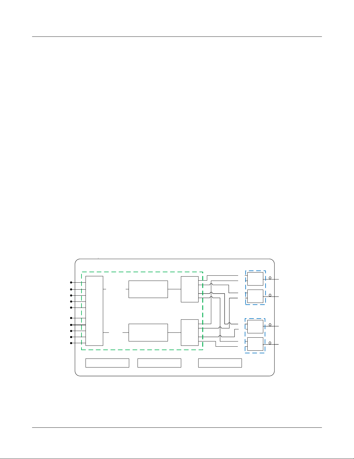
1.1 System Solution Block Diagram
The MBSC1900-040-RU platform allows flexible system deployment to support mixed mode 700~2700MHz
services in SISO configurations.
1.1.1 Host Unit
Figure 1Block Diagram of Host Unit
MBSC-C RU December 15, 2015
Page 1
Page 11
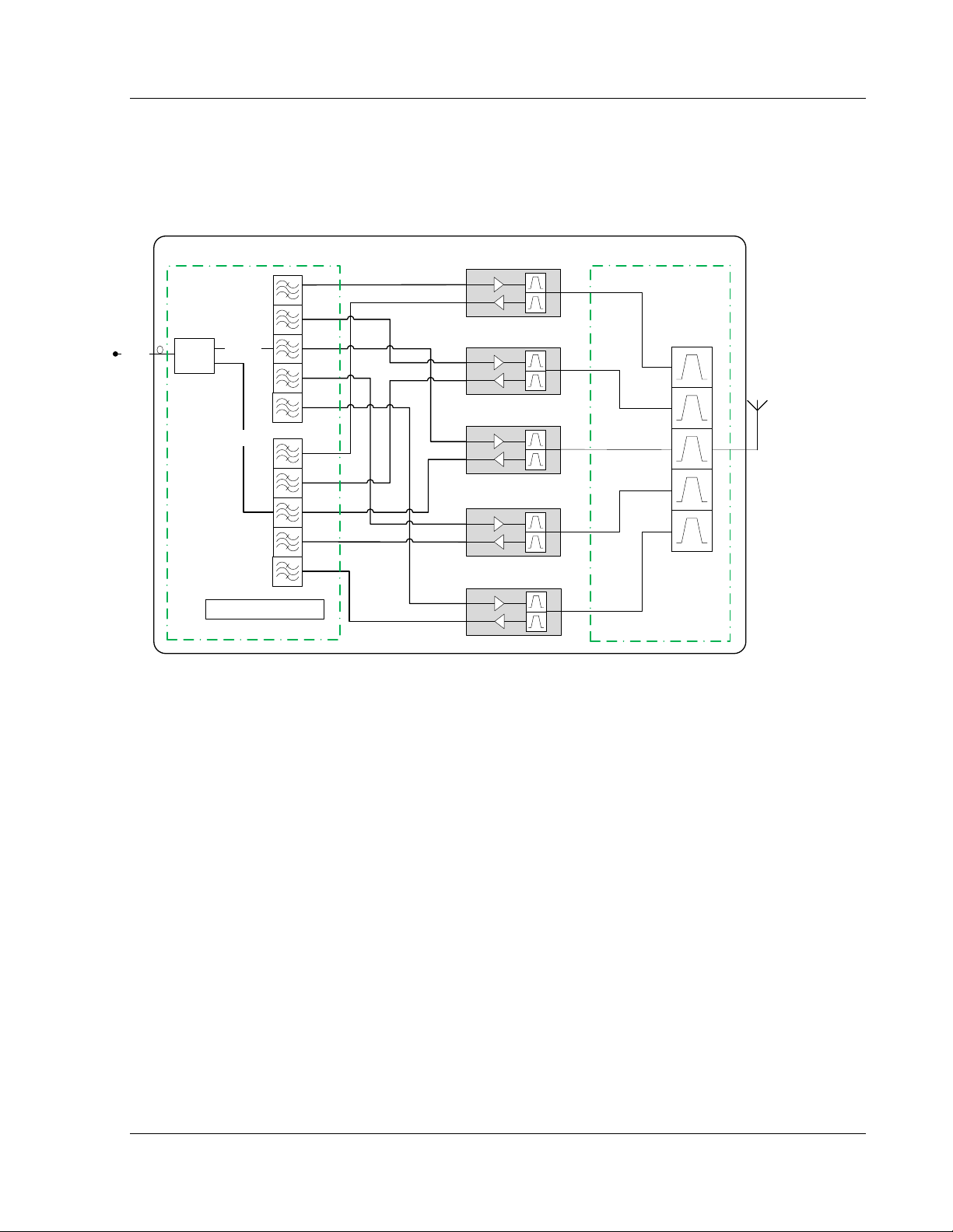
1.1.2 Remote Node
Downlink
Uplink
O/E
0.7~2.6G
Control Unit
REMOTE NODE (5 Bands deployed)
ANT-TX/RX
700/
850/
1900/
2100/
2600
CM-BTS
CM-ANT
2600MHz
2100MHz
1900MHz
850MHz
700MHz
MBSC-C RU
Figure 2 Block Diagram of Remote Node
MBSC-C RU December
15, 2015
Page 2
Page 12
MBSC-C RU
2 Safety
Caution
All the following “Safety Precautions” must be observed during the entire installation and operatio n of the mBSC system.
1. The mBSC system is designed for maximum safety and reliability when installed, used, and maintained
by trained and qualified technicians in accordance wit h the procedures and instructions contained in
this manual. To assure the safe operation of your system, always follow the safety and operational
recommendations in this manual.
2. Read and understand all instructions and warnings before handing the mB SC system.
3. Warning: Do not install or operate mBSC system in the presence of flamm abl e gases or fumes.
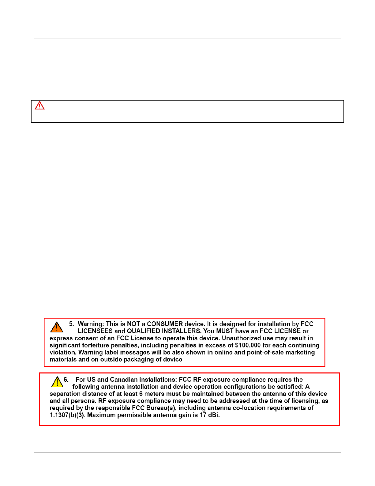
4. Warning: mBSC system produces high level of RF radiation.
5. Do not operate expos ed circuitry or radiating elements with personnel in close proximity to radiating
source.
6. Persons wi th cardiac pacemakers should avoid exposure to RF radiating elements.
7. Exposing the human eye to high levels of radio-frequency radiation may result in the formation of
cataracts.
8. Warning: We do not provide t he antenna; the antenna and other cable set provide b y customs . Please
don’t use unauthorized antennas, cables, and/or coupl i ng devices.
9. Warning: To avoid injuries or damage, use care and obtain assistance before lifting the mBSC unit.
10. Warning: mBSC sy stem should be installed only in restricted access areas (dedicated equipment room,
equipment closet, or similarity designat ed areas) where acc ess is controlled or where ac cess can only
be gained by service personnel with a key or tool . Access to this equipment is restricted to qualified
service personnel only.
MBSC-C RU December 15, 2015
Page 3
Page 13
MBSC-C RU
3 System Overview and Unit Description
3.1 System Overview
The MBSC1900-040-RU system is a multi-operator, multi-band and multi-technology coverage system that
provides in-building / venue coverage for up to five operating bands. Large buildings typically int erfere with
the transmission or reception of cellular phone syst em signals by imposing high attenuation losses on the
RF signal. The mBSC system is designed to overcome these losses which otherwise make cellular
communications within buildings or structures difficult or impossible. With the mBSC system, cel lular phone
RF signals can be distributed to the interior areas of any building or structure to eliminate dead spots and
improve reception.
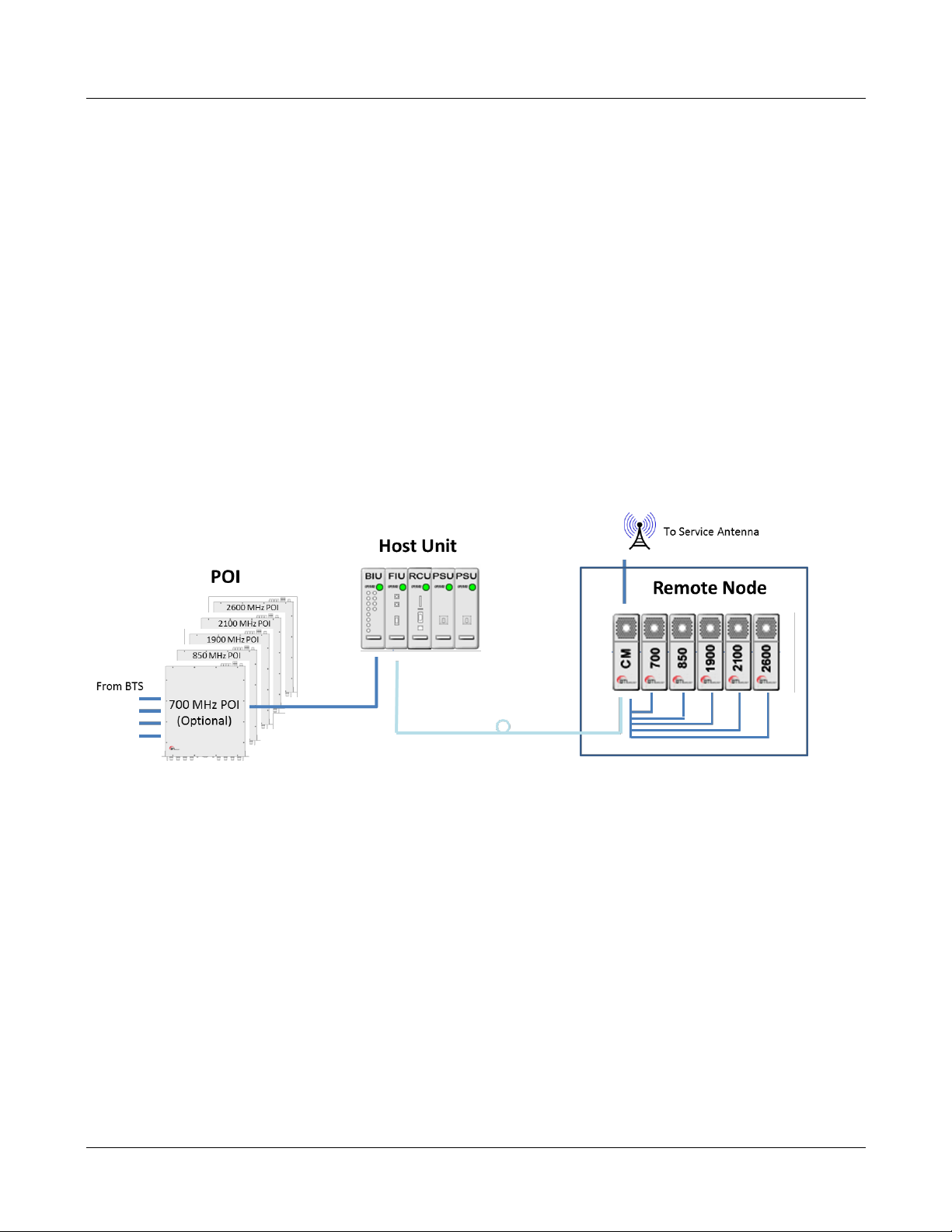
The MBSC1900-040-RUcoverage solution interconnects to, and extends, the wireless service provider base
station equipment (BTS) and service antennas. A functional overview is illustrated below.
Figure 3mBSC System Functional Overview
The mBSC system provides downlink signal amplification and uplink sensitivity improvement for multi-band
RF signals, which may be comprised of multiple carriers and m ult iple standards.
The Host Unit provides the input interface for RF s ignals from a base transceiver station (BTS). The Hos t
Unit converts the RF signals into a digital format and dist ributes the digitized signal over fiber to multiple
output ports. An optional Multi-operator Point-of-Interface (POI) combines multiband BTS inputs from
several operators into a single TXin / RXout interface to the Host Unit. Refer to “SP-MBSC-C-POI” for
additional details.
The Remote Node receives the optical signals from the Host Unit, converts the signals back into RF and
interfaces with the service antennas t o amplify the RF signal s throughout the building. The Rem ote Node is
typically wall-mounted within an equip m ent room.
3.1.1 Interface with BTS
The Host Unit is typically installed cl ose to the wireless service provider BTS equipment. In the downlink
path the Hos t Unit combines RF signals from up to 5bands and feeds the combined signal to a fiber-optic
MBSC-C RU December 15, 2015
Page 4
Page 14

MBSC-C RU
transceiver for transmission to the interconnected Remote Node(s).In the uplink path the Host Unit converts
a composite multi-band optical signal into independ ent RF signals for interconnecti on with the BTS receive
elements.
3.1.2 Interface with Cellular Phones
The mBSC Remote Node interfaces with the cellular phones through the service antennas. In the revers e
path, the Remote Node receives RF signals from cellular phones. In the forward path, the Remote Unit
transmits the RF signals to the cellular phones. A bi-directional antenna is connected to the mBSC Remote
Node to transmit and receive RF signals from the cellular phones.
3.1.3 Fiber Optic Transport
The Host Unit is connected to each Remote Node over a single optic al fiber. The opti cal fibers must be
terminated withE2000/APC connectors for connection with the Host Unit and the Remote Node.
3.1.4 Powering
The Host Unit is powered by -48V DC which is supplied by eit her the equipment room power distributio n
cabinet or an AC/DC converter. The Remote Node is powered by 110/220VAC, 50/60Hz power which is
supplied through a power supply distribution junction box.
3.1.5 Cooling
The Host Unit is cooled through cross-convect i on without fans.
The Remote Node contains multiple single-band R emote Units, which are cooled through continuous air
flow fans mounted on the top of each singe-band unit. A minimum of 200mm (7.87 inches) of clearance
space must be provided on both the top and the bottom sides of the Remote Node for air flow.
An alarm is provided that indicates if a high temperature condition occurs.
3.1.6 Fault Detection and Alarm Reporting
LED indicators are provided on the front panel of the Host Uni t to indicate i f the mBSC system is operating
as expected (normal) or if a fault i s det ect ed. In addition, normally open and closed al arm c ontacts (for both
major and minor alarms) are provided at the Host Unit for connection to a customer provided external alarm
system.
The mBSC system also includes a standalone (optional) Element Management System server, which
interconnects with each Host Unit in a multi-system deployment, and is used for system configuration, status
monitoring, and SNMP alarm reporting / management.
3.2 Host Unit Description
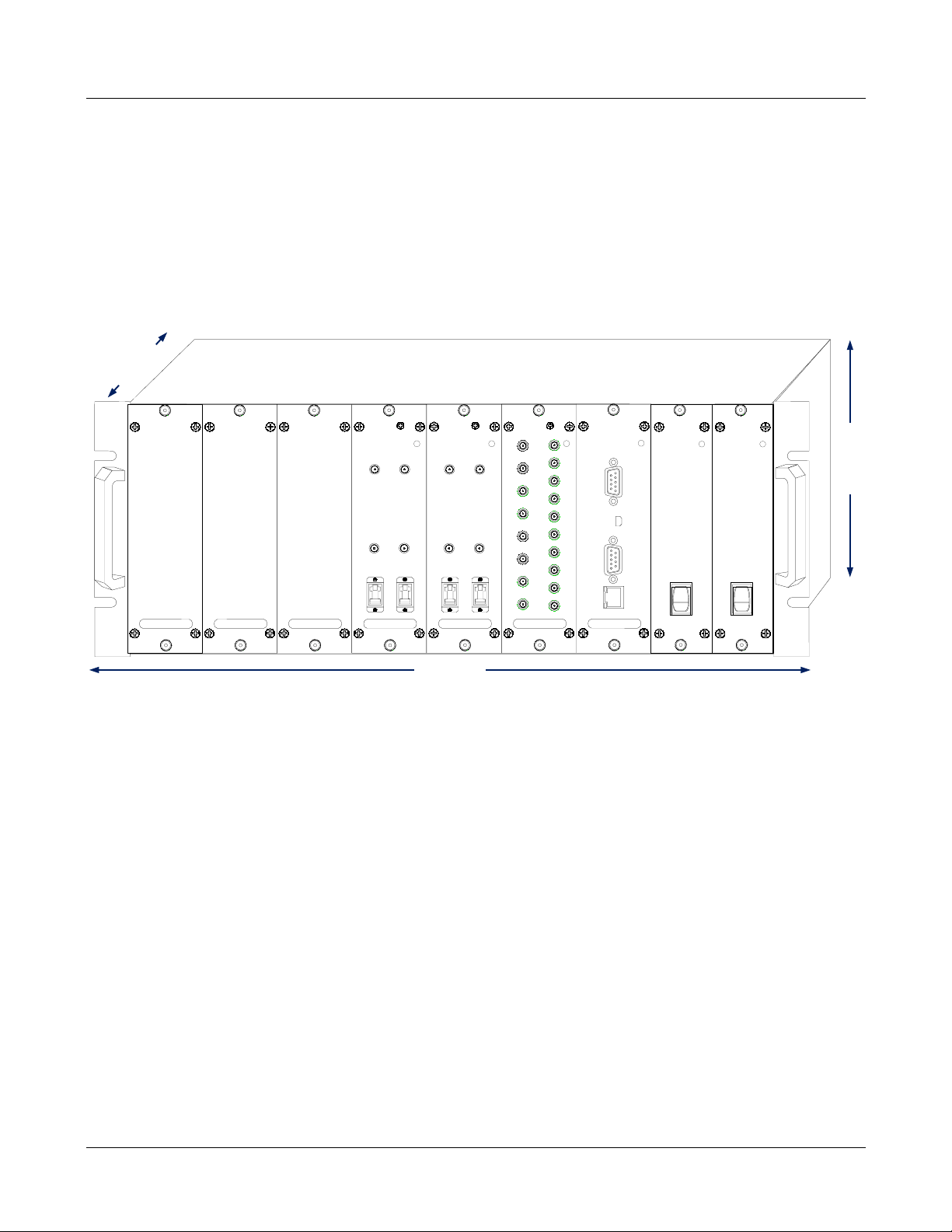
As shown in Figure 4, the Host Unit is a standard 19”4U rack-mounted shelf, which serves as the BTS
servicing unit for the mBSC system. The Host Unit provides t he following basic functions:
MBSC-C RU December 15, 2015
Page 5
Page 15
MBSC-C RU
PSU
1
0
PSU
1
0
177(6.97")
482.6(19")
405.95
(15.98")
FIU
Opreate
FIBER2
TX2
RX2
FIBER1
TX1
RX1
FIU
Opreate
FIBER2
TX2
RX2
FIBER1
TX1
RX1
BIU
Opreate
Tx700
Rx4
IN
Rx3
IN
Rx2
IN
Rx1
IN
Tx4
OUT
Tx3
OUT
Tx2
OUT
Tx1
OUT
Tx850
Tx1900
Tx2100
Tx2600
Rx700
Rx850
Rx1900
Rx2100
Rx2600
RCU
Opreate
RJ45
RS232
Modem
USB
RF interface with BTS (Simplex TXin, RXout)
Optical interface to Remote Nodes
Conversion of the forward path(downlink) RF signals into up to four simulcast optical signals
Conversion of up to four reserve(uplink) optical signals to RF signals
Manages and monitors the system alarms and configurations
Provides alarm information to a local alarm or remote system
Figure 4 Host Unit
3.2.1 Host Unit Components
The Host Unit is a multi-slot chassis, consisting of 9 slots numbered from left to right: 1 through 9. Sl ots 7
through 9 are dedicated and specifically keyed for the Remote Control Unit (RCU) and two redundant Power
Supply Units (PSUs). The Host Unit also houses the Base Station Interface Units (BIU) and Fiber Interface
Units (FIU). The Host Unit allows any combination of BIU and FIU modules, up to six in total.
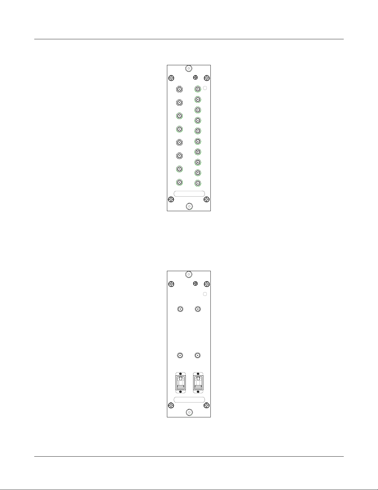
3.2.1.1 BIU (BTS Interface Unit)
The BIU is a frequency agnostic RF interface card that provides simplex TX input and RX output
connections to the BTS equipment. The BIU combines up to 5 bands of RF downlink signal into a composite
signal, which is then split across four TX out connectors for interconnection to up to four fiber modules
(simulcast). In the uplink path the BIU combines up to four separate multi-band uplink signals for distribution
to the BTS receivers. Internal splitters , combiners, and software controlled attenuators enable customized
designs to support various RF inputs scenarios.
MBSC-C RU December 15, 2015
Page 6
Page 16
BIU
Opreate
Tx700
Rx4
IN
Rx3
IN
Rx2
IN
Rx1
IN
Tx4
OUT
Tx3
OUT
Tx2
OUT
Tx1
OUT
Tx850
Tx1900
Tx2100
Tx2600
Rx700
Rx850
Rx1900
Rx2100
Rx2600
FIU
Opreate
FIBER2
TX2
RX2
FIBER1
TX1
RX1
MBSC-C RU
Figure 5BIU
3.2.1.2 FIU (Fiber Interface Unit)
The FIU provides the i nterface between the combined RF signals (BIU) and the optical fiber connect ions.
Each FIU is equipped for 2independent bi-directional fiber connections.
Figure 6FIU
MBSC-C RU December 15, 2015
Page 7
Page 17
MBSC-C RU
PSU
1
0
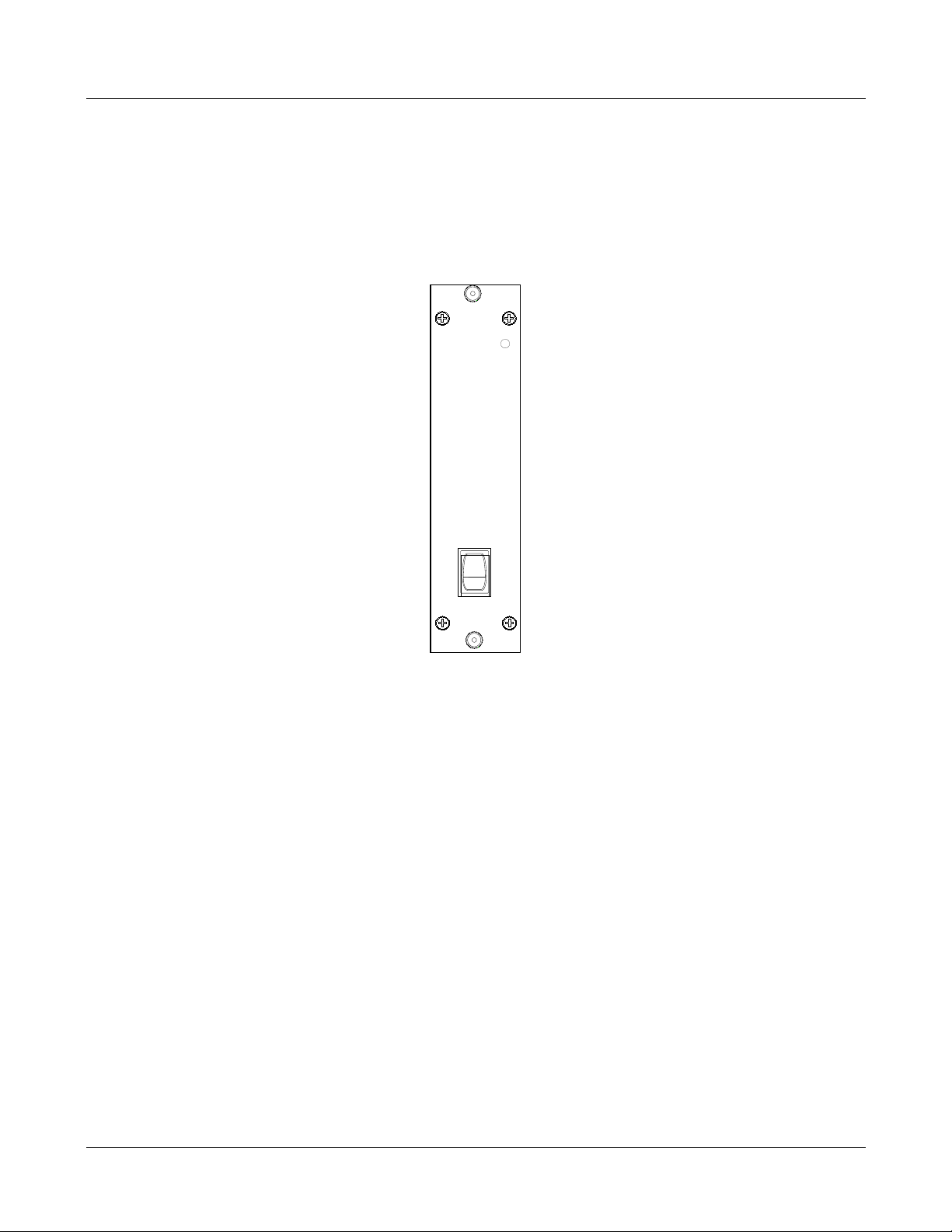
3.2.1.3 PSU (Power Supply Unit)
The Host Unit is powered by -48V DC. The PSU takes the -48 VDC input source power and provides voltage
conversion and distribution for the line cards installed within the host unit shelf. The host unit is equipped
with 2 independent PSU’s in parallel redundancy. Each PSU is hot swappable (one unit at a time only).
Figure 7 PSU
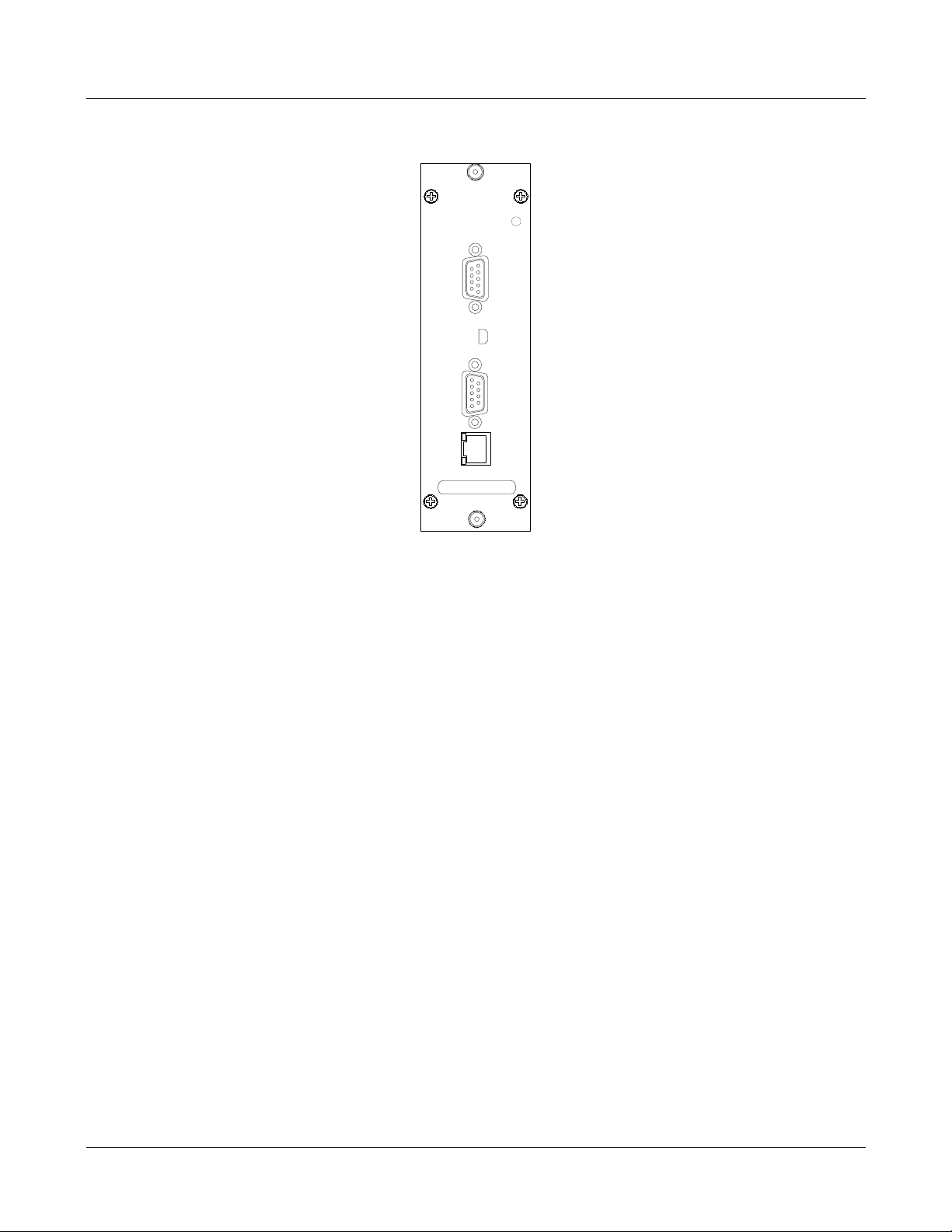
3.2.1.4 RCU (Remote Control Unit)
The RCU provides the control and interface f or a local Operations and Maintenance Console (OM C) GUI,
and a remote Element Management System (EMS) server through Ethernet or modem connection
(optional).
The RCU is a hot swappable card and will not affect operation of the RF path if removed.
MBSC-C RU December 15, 2015
Page 8
Page 18
RCU
Opreate
RJ45
RS232
Modem
USB
MBSC-C RU
Figure 8RCU
3.2.2 Mounting
The Host Unit is intended for use in indoor, rack-mounted applications. For rack mounting, a pair of
mounting brackets is provided that allows the Host Unit to be mounted in a 19” equipment rack. When
rack-mounted, the front panel of the Host Unit is flush with the front of the rack.
3.2.3 Fault Detection and Alarm Reporting
The Host Unit detects internal circuitry faults and optical port faults. Various front panel LED indicators turn
from green to red if a fault is detected or an optical input is lost. A set of dry-contact alarm points(normally
open and normally closed) are also provided for interfacing with an external alarm system .
3.2.4 RF Signal Connections
RF signal connections with the BTS are support ed through two QMA female connectors per RF Band (5
bands supported). One QMA connector per band is used for coaxial cable connection of the combined
downlink path (TXin) RF signal. The other QMA connector is used for coaxial cable connection of the
combined uplink path (RXout) RF signal.
Notes: The input RF signal level range to Host Unit is -10dBm - +10dBm, normally it is between -5~0dBm.
3.2.5 Optical Connections
The Host Unit optical connections to the Remote Unit are supported on th e Fiber Interfac e Unit (FIU). Each
FIU supports two independent optical paths, each consisting of a status LED, two QMA RF connectors, and
anE2000/APC optical transceiver using single-m ode fiber. Up to five bands of non-overlapping RF signal
can be transported across a single fiber.
MBSC-C RU December 15, 2015
Page 9
Page 19

MBSC-C RU
User Interface
Designation
PSU
RCU
BIU
Band-specific Downlink input from BTS
(one QMA per band, up to 5 bands)
Band-specific Uplink output to BTS
(one QMA per band, up to 5 bands)
Combined multi-band Downlink signal output to up to four
independent fiber paths (on FIUs)
Combines multi-band Uplink signal inputs from up to four
Enclosure Rear Panel
3.2.6 Powering
The Host Unit is powered by -48V DC through a DC power terminal bloc k on t he r ear. An ON/OFF switch is
provided at the PSU front panel. The switch applies power t o the Host Unit internal power supply, which
distributes the operating voltages to lines cards installed in the Hos t Unit shelf.
3.2.7 Host Unit Interface
The Host Unit interface consists of the various connectors, switches, terminals and LED indicators that ar e
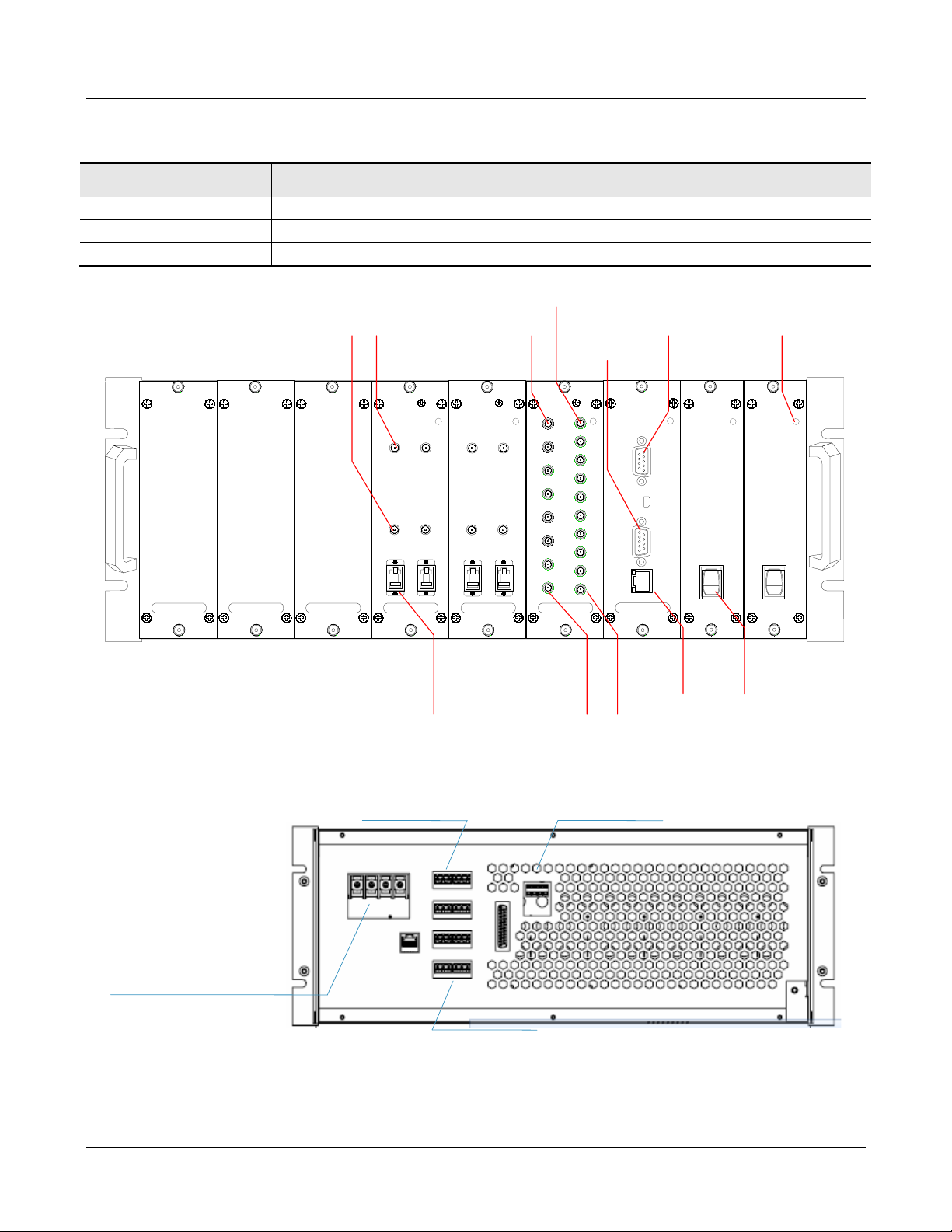
provided on the front and rear panel. The Host Unit user interfaces are described in Table 1and indicated in
Figure 9.
Table 1 Host Unit User Interface
#
1 ON/OFF Power switch Enable/disable Host Unit internal power supply
2 Power LED(Green/Off) Indicates if the PSU is powered on or off.
1 Modem (optional) DB9(male) Used for external wired modem connection
2 RS232 (optional) DB9(female) Local connection from PC/Laptop through serial cable
3 RJ45 RJ45 jack (female) Ethernet connection interface for NMS
4 USB Mini USB (female) Used for USB connection for local GUI
5 Operate LED(Green/Red) Indicates if the RCU is normal or faulty
1 Tx (700~2600) QMA female connector
2 Rx (700~2600) QMA female connector
3 Tx1~Tx4 QMA female connector
4 Rx1~Rx4 QMA female c onnector
5 Operate LED(Green/Red) Indicates if the BIU is normal or faulty
FIU
Note: The power input port is provided according to the power in type.
Device Functional Description
independent fiber paths (on FIUs)
1 Tx (1~2) QMA female connector Composite Downlink RF input from BIU
2 Rx (1~2) QMA female connector Composite Uplink RF output to BIU
3 Fiber (1~2)
4 Operate LED(Green/Red) Indicates if the FIU is normal or faul ty
1 Alarm In Screw-type terminal block Alarm contacts - inputs from an external alarm system
2 Alarm Out Screw-type terminal block Alarm contacts – outputs to an external alarm system
3 DEBUG DB19 male connector Local serial connection for debug by BTI staff only
MBSC-C RU December 15, 2015
E2000/APC WDM optical
transceiver
Fiber connection to Remote Node ( 2 per FIU)
Page 10
Page 20
User Interface
Designation
PSU
1
0
PSU
1
0
FIU
Opreate
FIBER2
TX2
RX2
FIBER1
TX1
RX1
FIU
Opreate
FIBER2
TX2
RX2
FIBER1
TX1
RX1
BIU
Opreate
Tx700
Rx4
IN
Rx3
IN
Rx2
IN
Rx1
IN
Tx4
OUT
Tx3
OUT
Tx2
OUT
Tx1
OUT
Tx850
Tx1900
Tx2100
Tx2600
Rx700
Rx850
Rx1900
Rx2100
Rx2600
RCU
Opreate
RJ45
RS232
Modem
USB
Composite RF
Tx Connector
(1~2)
Composite RF
Rx Connector
(1~2)
Optical
Transceiver Port
(1~2)
LED
Indicator
Power ON/OFF
Switch
Ethernet
Connector
5-band RF Tx
Connector
(1~4)
RF Rx
Connector
(700~2600MHz)
RF Tx
Connector
(700~2600MHz)
5-band RF Rx
Connector
(1~4)
Serial Port
External Wired
Modem Connector
-48 VDC
redundant
connections
POI Fan Power
interface and monitor
Dry Contact (Form C) alarm output
Input Alarms
MBSC-C RU
#
Device Functional Description
4 Power Input Screw-type terminal block -48VDC power input
5 POI FAN (optional) Screw type terminal +12VDC for external power connect ion
6 NETWORK RJ45 jack (female) Optional Ethernet connection
MBSC-C RU December 15, 2015
Front Panel
Figure 9 Host Unit User Interface
Rear Panel
Page 11
Page 21

#
Indicator
Status
Description
Table 2Host Uni t Indicator Description
MBSC-C RU
1 RUN
Green(Flashing) Normal system operation
Red(Flashing) System fault detected
3.3 Remote Node Description
The Remote Node serves as the remote interface unit for the fiber optic mBSC system. It is comprised of a
mounting bracket and enclosure for up to five single-band Remote Units (RUs) and a Fiber/Antenna
combiner unit. The Remote Node provides the following basic func tions:
RF interface to the mobile end-systems via an external service antenna
Optical interface to the Host Unit FIU
Conversion of the forward path(downlink) optical signal to original RF signal
Conversion of the reverse path(uplink) RF signal to an optical signal
Transports alarm status over the optical fiber
Supplies in-band messaging between the Host Unit and the Remote Node for Remote Node
alarms and configuration
3.3.1 CM-BTS/ANT Enclosure
The CM-BTS/ANT module provides two key functions:
1. Electrical-optical/optical-electrical signal conversion and separates the combined multi-band RF
signals into simplex connections for delivery to the respective single-band RU Enclosures
2. Combines the RF signals from each single-band RU Enclosure for duplex interconnection with the
service antenna
MBSC-C RU December 15, 2015
Page 12
Page 22
MBSC-C RU
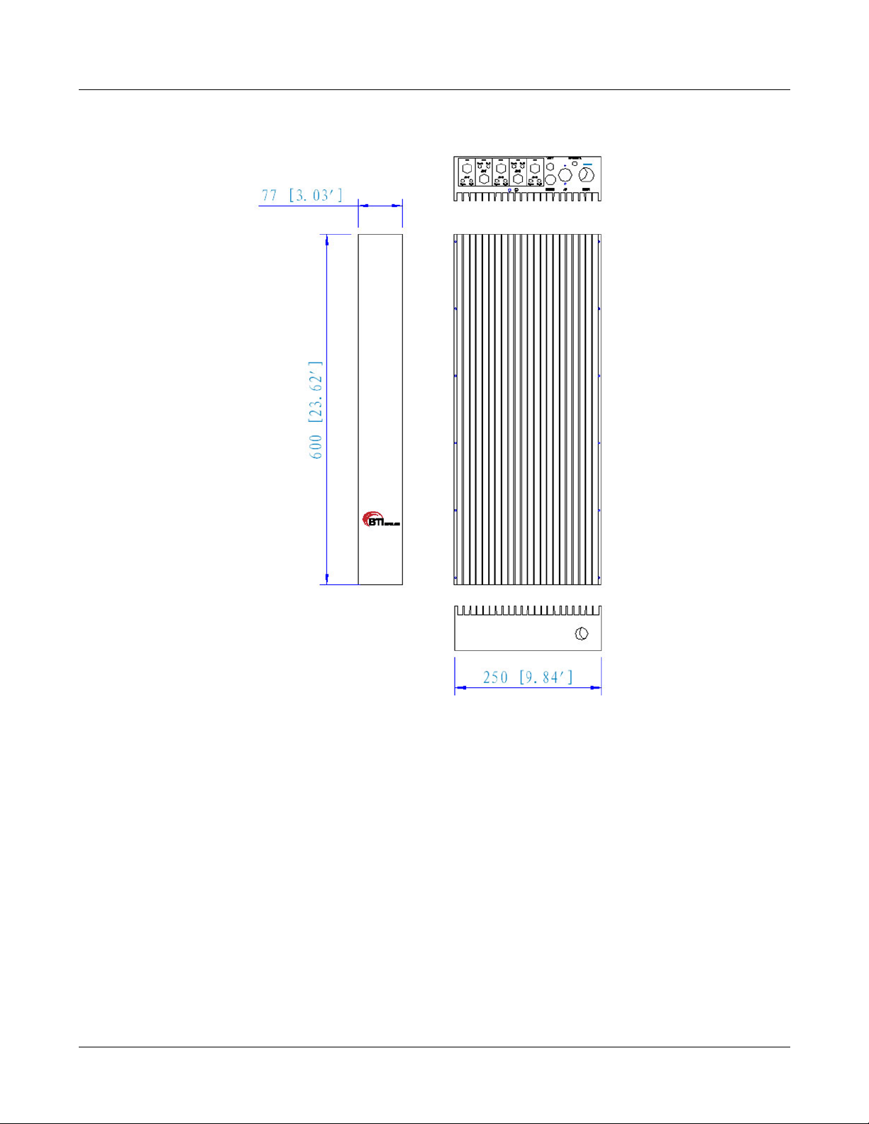
Figure 10Fiber CM-BTS/ANT Enclosure Outline
3.3.1.1 Primary Components
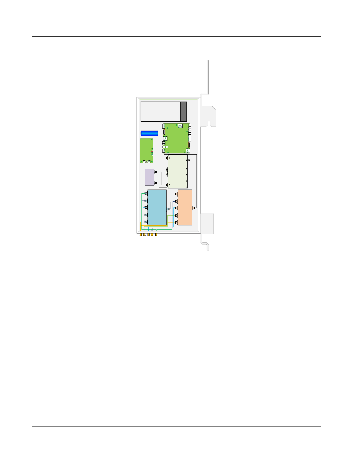
The fiber CM-BTS enclosure i nterior layout, shown in Figure 11, is equipped to interface up to five bands
(700MHz, 850MHz, 1900MHz, 2100MHz and 2600MHz). The enclosure includes weatherproof housing,
mounting brackets, and internal multiplexer, duplexer, RF-optic transceiver, control unit and power supply
unit elements.
MBSC-C RU December 15, 2015
Page 13
Page 23
OPTIC IN/OUT
RF-Optic Transceiver
RF OUT
RF IN
收无光 电源 发无光
锂电池
580889640102-battery board
700850
2100
1900
2600
TX
A
700850170018002600
RX
MBSC-C RU
Figure 11Fiber CM-BTS/ANT Interior Layo ut
3.3.1.1.1 Power Supply Module
Power Supply Module provides stable power to fiber CM-BTS unit. Power Supply Mo dule is supplied with
110/220V AC.
3.3.1.1.2 Multiplexer & Duplexer
The multiplexer separates the various band frequencies respectively. The duplexer is used to make the
bi-directional signals into simplex signal s and provides sufficient isolation.
3.3.1.1.3 RF-Optic Transceiver
The RF-Optic Transceiver is an optical module providing conversion between RF signals and optical signals
over a single fiber. The optical module converts the downlink optical signal from the FIU module in t he host
unit, and it also converts the uplink RF signal to an optical signal and simul taneously sends it back to FIU
module in the host unit for distribution to the BI U modules. A laser and received optical power monitor and
alarm are provided.
MBSC-C RU December 15, 2015
Page 14
Page 24
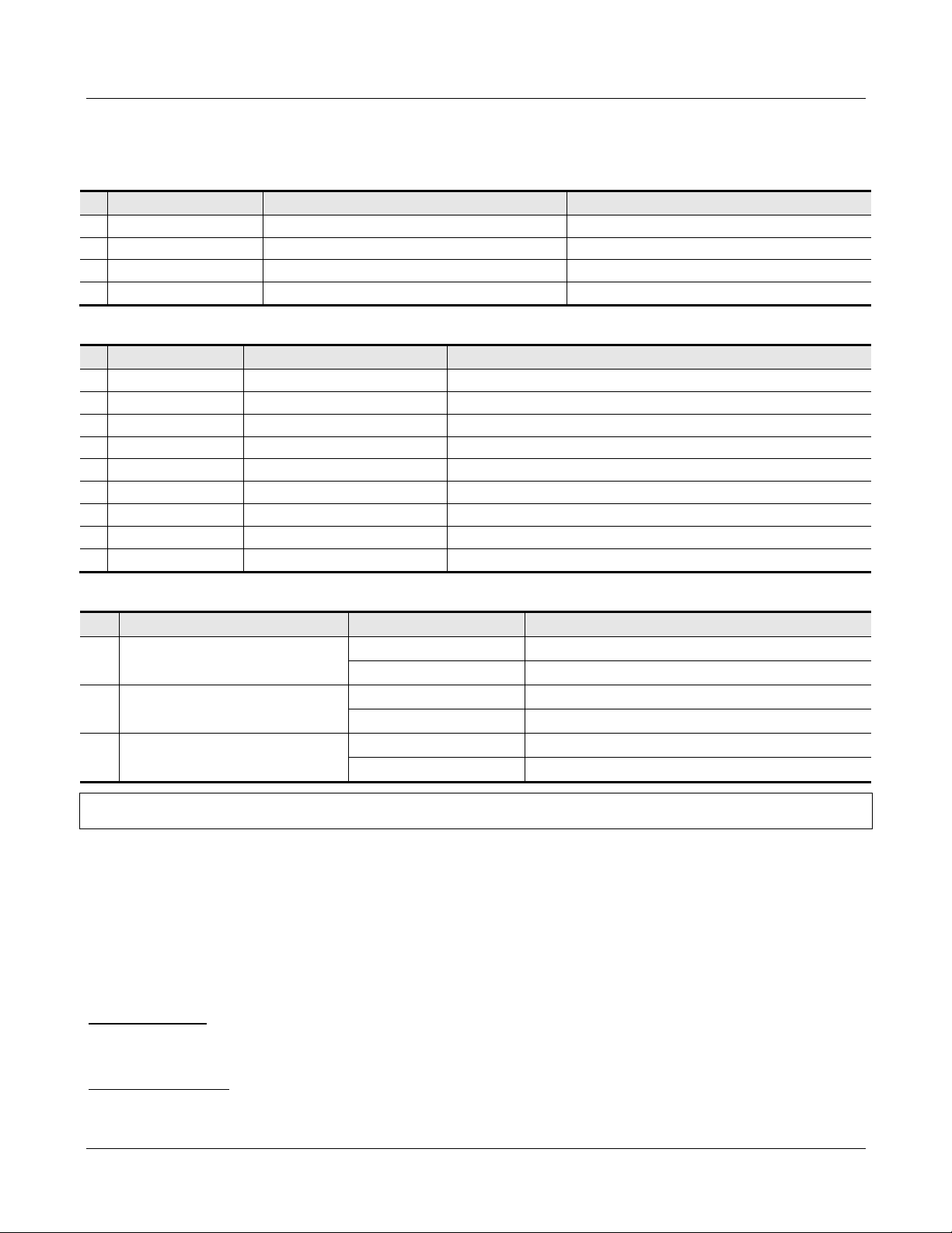
Port
Device
Description
#
PIN
Definition
Description
Table 3 RF-Optic Transceiver Interface
#
1 RF O UT QMA\SMA female coaxial connector RF output
2 RF I N QMA\SMA female coaxial connector RF input
3 OPTIC IN/OUT E2000/APC Fiber interface (HU & RN)
4 --- DB9 female Power supply & monitoring
Table 4 DB9 PINOUTS
1 PIN1 NC
2 PIN2 GND
3 PIN3 VCC +12V DC
4 PIN4 TXD1/B1 Channel1: RS485-B1
5 PIN5 RXD1/A1 Channel1: RS485-A1
6 PIN6 RXD0/A0 Channel0: RS485-A0
7 PIN7 LD ALM Laser Device error
8 PIN8 TXD0/B0 Channel0: RS485-B0
9 PIN9 PD ALM Photo-detector error
MBSC-C RU
Table 5 RF-Optic Transceiver Indicators
# Indicator Status Description
1 POWER
2 PD ALARM
3 LD ALARM
Notes: If the fiber is not connected properly, both of the HU and RN’s PD ALARM indicator will alarm (red LED). Otherwise the
indicator is off.
Green Normal
Off No power supply
Off Photo-detector works
Red Photo-detector error
Off Laser Device works
Red Laser Device error
3.3.1.2 Mounting
The fiber CM-BTS/ANT enclosure is hanging-mounted on the mounting brack et.
3.3.1.3 RF Connection
Optical Module: The RF signal connec tions with the optical fiber module are support ed through 5 groups of
SMA female connectors. These five connector groups are used for coaxial cable inter-connection of the
simplex Tx and Rx RF signals to the single-band RU enclosures.
Antenna Combiner: The RF signal connections with the antenna combiner are s upported through 5 N-type
female connectors. These five N-type connectors are used for coaxial cable connection to the Antenna ports
of the single-band RU enclosures. A si ngle 7/16 DIN connector is used to interface the combined multi-band
MBSC-C RU December 15, 2015
Page 15
Page 25

MBSC-C RU
Model FCM-CN-C
QMA\SMA female RF coaxial
connector
QMA\SMA female RF coaxial
connector
RF duplex Tx/Rx inter-connection from ANT of
single-band RU
Used for connecting a grounding cable to the
enclosure
RF signal to the service antenna.
3.3.1.4 Optical Port
The fiber CM-BTS enclosure uses anE2000/APC type optical transceiver for inter-connecting the optical
fiber. The transceiver supports single-mode (yellow) fiber.
3.3.1.5 Powering
The fiber CM-BTS/ANT enclosure is equipped with a 4-wire AC power connector that provides a connection
point for the AC power cable distributed from the power dist ribu t ion junction box. The CM-BTS/ANT module
is powered by 110/220V AC.
3.3.1.6 User Interface
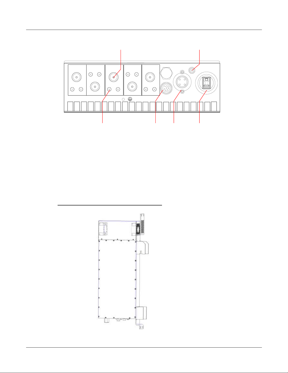
The fiber CM-BTS/ANT enclosure interface consists of the various connectors, terminals and LED indicators
that are provided on the chassis panel. The fiber CM-BTS enc losure user interface is described in Table
6and indicated in Figure 12.
Table 6Fiber CM-BTS/ANT Enclosure User Interface
# User Interface Designation Device Functional Description
1 Fiber E2000/APC optical connector Used for fiber connecting to host unit
2 Operation LED (Green/Red/Off) Indicates if Fiber/RF link is normal or faulty.
3 TX(700~2600)
4 RX(700~2600)
5 ANT N female RF coaxial connector RF duplex Tx/Rx connection to antenna
6 700~2600 TxRx N female RF coaxial connector
7 DEBUG 8-PIN circular plug Used for local serial RS232 connecti on
8 AC
9
4-wire circular push-plug power
connector
Grounding stud
RF inter-connection to TX_IN of single-band unit
RF inter-connection to RX_OUT of single-band unit
Used for connecting AC 110/220V power input.
MBSC-C RU December 15, 2015
Page 16
Page 26
B
TX_OUT
RX_IN
A
TX
_OUT
RX_
IN
B
TX
_OUT
RX
_IN
A
TX
_
OUT
RX_IN
B
TX_
OUT
RX_
IN
VENT
DEBUG
AC FIBER
ANT
ANT
ANT
ANT
ANT
OPERATE
700
850
2600
21001900
Optical Connector
AC 110
/220
V
Power IN
Local Debug
Serial Port
LED Indicator
RF Input Connector from
Single-band BDA Unit
RF Inter
-
Connector to
Single-
band BDA Unit
MBSC-C RU
Combiner Model FCM-CN-C
Figure 12Fiber CM-BTS/ANT Enclosure User Interface
3.3.2 Single-band RUEnclosure
The Single-band Remote Unit (RU) enclosure provides forward and reverse amplific ation of the RF signals
within the specified band. Its enclosure accommodates the remote single-band modules and protects them
from the environment. The enclosure consists of the housing, mounting brackets, and enclosed MCPA
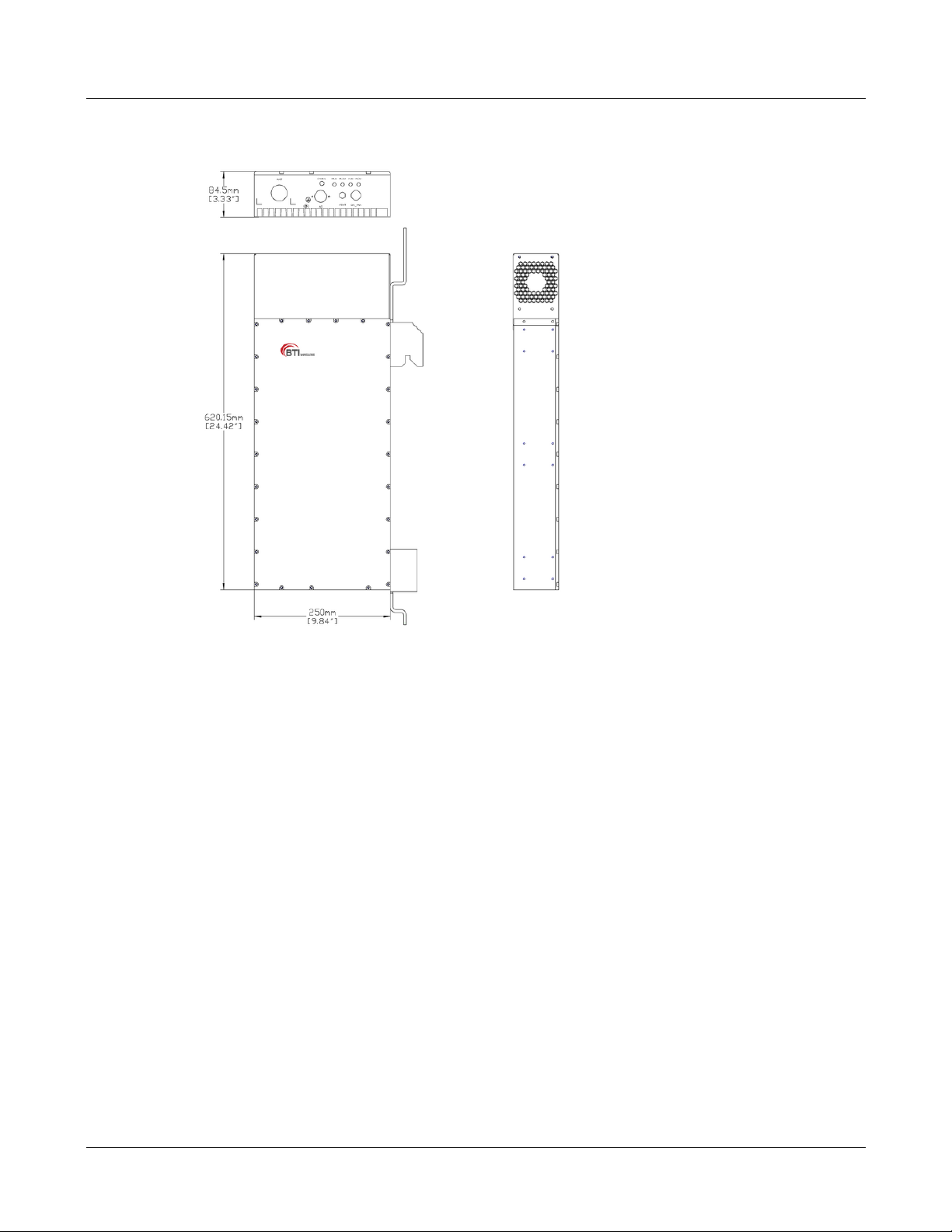
(Multi-Carrier Power Amplifier), power supply, controller unit, duplexer modules. Figure 13 shows the
single-band enclosure dimensions.
700MHz, 850MHz, 1900MHz, 2100MHz and 260 0MHz
MBSC-C RU December 15, 2015
Page 17
Page 27
MBSC-C RU
Figure 13Single-band RU Enclosure
3.3.2.1 Primary Components
3.3.2.1.1 Multi-Carrier Power Amplifier (MCPA) Modules
The MCPA Module is the heart of the mBSC RU Enclosure. The MCPA Module boosts the BTS forward link
transmission signal. Operating on28V DC input, the MCPA Module produces 10W or 20 W com posite RF
power for each band (measured at output of the antenna combiner).
The mBSC system provides linear amplification of multi-carrier, mixed-mode signals in the 700MHz,
850MHz, 1900MHz, 2100MHz and 2600MHz frequency bands with the respective RU’s.
3.3.2.1.2 LNA (Low Noise Amplifier)
The LNA amplifies the reverse link signal wi th alow-noise amplifier and then sends it t o the input duplexer
assembly.
3.3.2.1.3 MCU (Micro Controller Unit)
The MCU provides communications with power amplifier module and CM-BTS. The MCU also monitors and
adjusts the rotational speed of the cooling fans to maintain nominal system operating temperature.
MBSC-C RU December 15, 2015
Page 18
Page 28

MBSC-C RU
User Interface
Designation
4-wire power cord with circular
push-plug connector
3.3.2.2 Mounting
The single-band RU enclosure is hanging-mo unted on the mounting bracket.
3.3.2.3 RF Connection
The RF signal connections with the singl e-band enclosure are supported t hrough two SMA female coaxial
connectors and one 7/16” DIN female connector. The two SMA female connectors are used for coaxial cable
connection (RF jumper) of the Tx and Rx RF signals between the CM-BTS/ANT enclosure and the
single-band RU enclosure. The 7/16” DIN female connector is used for coaxial cable connection of the
amplified duplex Tx/Rx RF signal to the CM-BTS/ANT enclosure.
3.3.2.4 Cooling
The single-band RU enclosure is cooled by continuous air flow fans mounted on the t op of the casing. A
minimum of 200mm (7.87 inches) of clearance space must be provided on both the top and the bottom sides
of the Remote Node for air convection.
An alarm is provided that indicates if a high temperature condition occurs.
3.3.2.5 Powering
The single-band RU enclosure is equipped with a 4-wire AC power con nector that provides a connection
point for the AC power cable distributed from the power distribution junction box. The single-band RU
enclosure is powered by 110/220V AC.
3.3.2.6 User Interface
The single-band RU enclosure user interface includes the various connectors that are provided on the
exterior enclosure. The user interface is described in Table 7, and indicated in Figure 14.
Table 7Single-band BDA Enclosure User Interface
#
1 AC
2 ANT N type female RF coaxial connector RF (Tx/Rx) inter-connection to CM-ANT/BTS enclosure
3 Tx-IN SMA female coaxial connector RF inter-conne c tion to CM-BTS/ANT Tx In
4 Rx-OUT SMA female coaxial connector RF inter-connection to CM-BTS RxOut
5 FAN 8-pin circular push-plug connector DC power to fans
6 RUN LED (Green/Red/Off) Indicates if unit operation is normal or faulty.
Device Functional Description
Used for connecting AC110/220VAC power input.
MBSC-C RU December 15, 2015
Page 19
Page 29
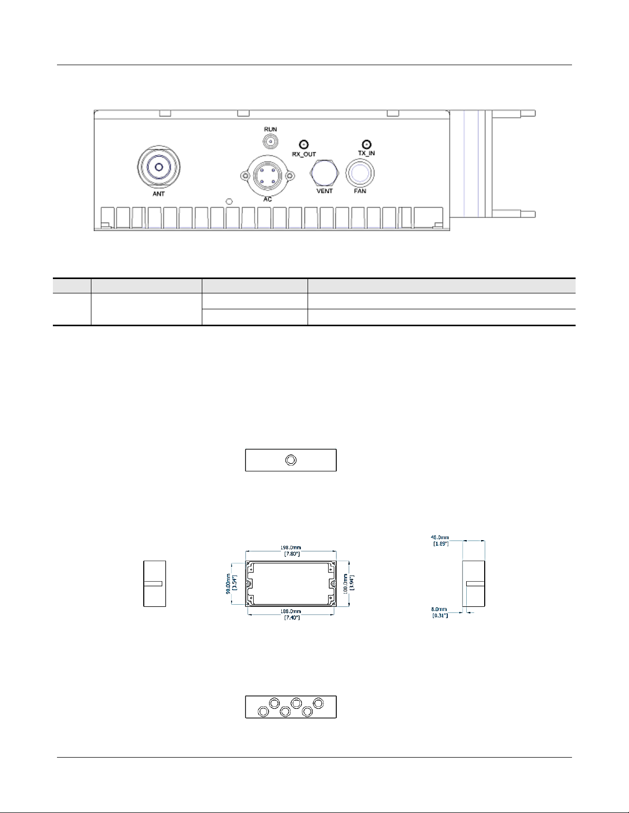
Figure 14 Single-band RU Enclosure User Interface
Table 8 Indicator Description
# Indicator Status Description
1 RUN
Green(Flashing) System operating normally
Red(Flashing) System alarm
MBSC-C RU
3.3.3 Power Supply Junction Box
The power supply junction box provides power connect ion and distribution to each enclo sure. The Junction
Box provides a single 3-wire AC power cord for direct t ermination to the AC input power source (110/220
VAC), and four or six supply cords (depending o n shroud size) with 4-pin Amphenol power c onnectors for
powering the RUs and the CM-BTS/ANT Combiner,
Figure 15Power Box Outline
MBSC-C RU December 15, 2015
Page 20
Page 30

MBSC-C RU
3.3.4 Shroud& Bracket
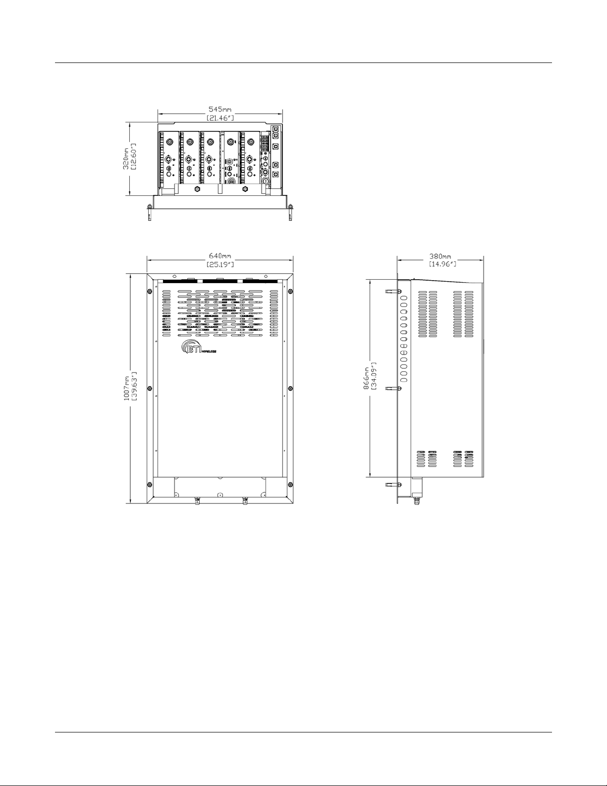
The Remote Node has a shroud cover for therm al protection. The shroud features are as below:
Construction
All in aluminum
Corrosion protection to the entire cabinet
Cabinet ingress protection to be IP53
Powder coat neutral beige
Table 9Shroud Specification
Mechanical Specification Description
Material construction Aluminum
Shroud & bracket weight
Dimension (H x W x D)
With panel bracket
3-band unit: 16 kg (35.3 lbs)
5-bandunit: 26 kg (57.3 lbs)
3-band unit: 1006 x 460 x 380 mm (39.6” x 18.1” x 15.0”)
5-bandunit: 1006 x 640 x380 mm (39.6” x 25.2” x 15.0”)
MBSC-C RU December 15, 2015
Page 21
Page 31
MBSC-C RU
Figure 16Remote Unit Shroud
MBSC-C RU December 15, 2015
Page 22
Page 32

MBSC-C RU
4 System Installation
4.1 Unpacking and Inspection
Every mBSC-C component has been tested and calibrated at the factory. Unpack the mBSC-C components
carefully after they arrive at the installation site. Open the wooden container and remove the foam padding.
If the equipment is damaged:
Immediately contact the transportation and notify them of the damage.
A claim shoul d be filed with the carrier once the extent of any damage is assessed.
If possible, always inspect the equipment in the presence of the delivery person.
If the equipment is damaged and must be returned to BTI’s nearest RMA facility:
Log on the BTI website, or call 714-230-8333for a return authorization.
BTI will not accept returns without a RMA number.
Claims for loss or damage may not be withheld from BTI, nor may any payment due be with held pending
the outcome thereof.
BTI CANNOT be held responsible for the freight carrier’s performance.
4.2 Installation Preparation
4.2.1 Required Tools
The following equipment and tools may be required for a successful installation:
Multi-meter
Phillips screwdrivers
Flat blade screwdrivers
Wrenches
Drill
VSWR testing device
N adapters
RF testing cables
RF Power meter (part of hand-held tester)
4.2.2 Installation Location
The mBSC Host unit is typically installed within a 19” rack:
MBSC-C RU December 15, 2015
Page 23
Page 33

MBSC-C RU
The rack should be selected with adequate shelf space to accommodate the Host Unit equipment
with adequate space for ventilation around each component
The rack must be able to support the weight of the equipment to be i nstalled
The mBSC Remote unit is typically installed on the wall:
The wall should be water-resistant, dry, non-caustic and without high-voltage power leaking.
The wall’s bearing capacity is more than 136kg.
Concrete wall sand brick walls are recommended, because those walls can accept expansion
screws. Masonry walls or sandy-dust walls are not suitable.
4.2.3 Anti-corrosion and Shock-protection
To safeguard products and operators, the installation location must be kept away from caustic or poisonous
pollutants. If the site can’t meet seismic standards, it must be properly reinforced.
4.2.4 Lighting, Ventilation and Fire Protection
The installation site should have enough illuminat ion for installation and maintenance needs. Flammable
and explosive material should not be near the site.
4.2.5 Power Requirements
Nominal voltage:
Remote Unit: 110/220VAC +/- 20%, 50/60 Hz +/-5%.
Host Unit: -48VDC. Variable range: -36 ~ -72 V DC.
The power consumption of the mBSC Remote Node is approximately 220W per band. Make sure to select a
fuse or breaker with the proper capacity. A 10A breaker is recommended @ 220VAC.
4.2.6 Lightning Protecting and Grounding
The cross section of grounding cable should be no smaller than 25mm2. The grounding c able should be
connected to earth ground directly without any splices. Keep the grounding cable as short as possible.
MBSC1900-040-RU system design complies wi th the criteria of IEC61000-4-5 and ETS 300 342-2/3.
4.3 Host Unit Installation
4.3.1 Rack Mounting
The Host Unit is a 19” 4U equipment shelf. When loading the Host Unit in a rack, make sure the mechanical
loading of the rack is even to avoid a hazardous condition. The rack should safely support the combined
MBSC-C RU December 15, 2015
Page 24
Page 34
MBSC-C RU
weight of all the equipment and be securely anchored. I nstalling the Host Unit in a room with sufficient air
circulation is recommended as the maximum ambient temperature for Host Unit is 60°C.
Use the following steps to install the Host Unit in the equipment rack:
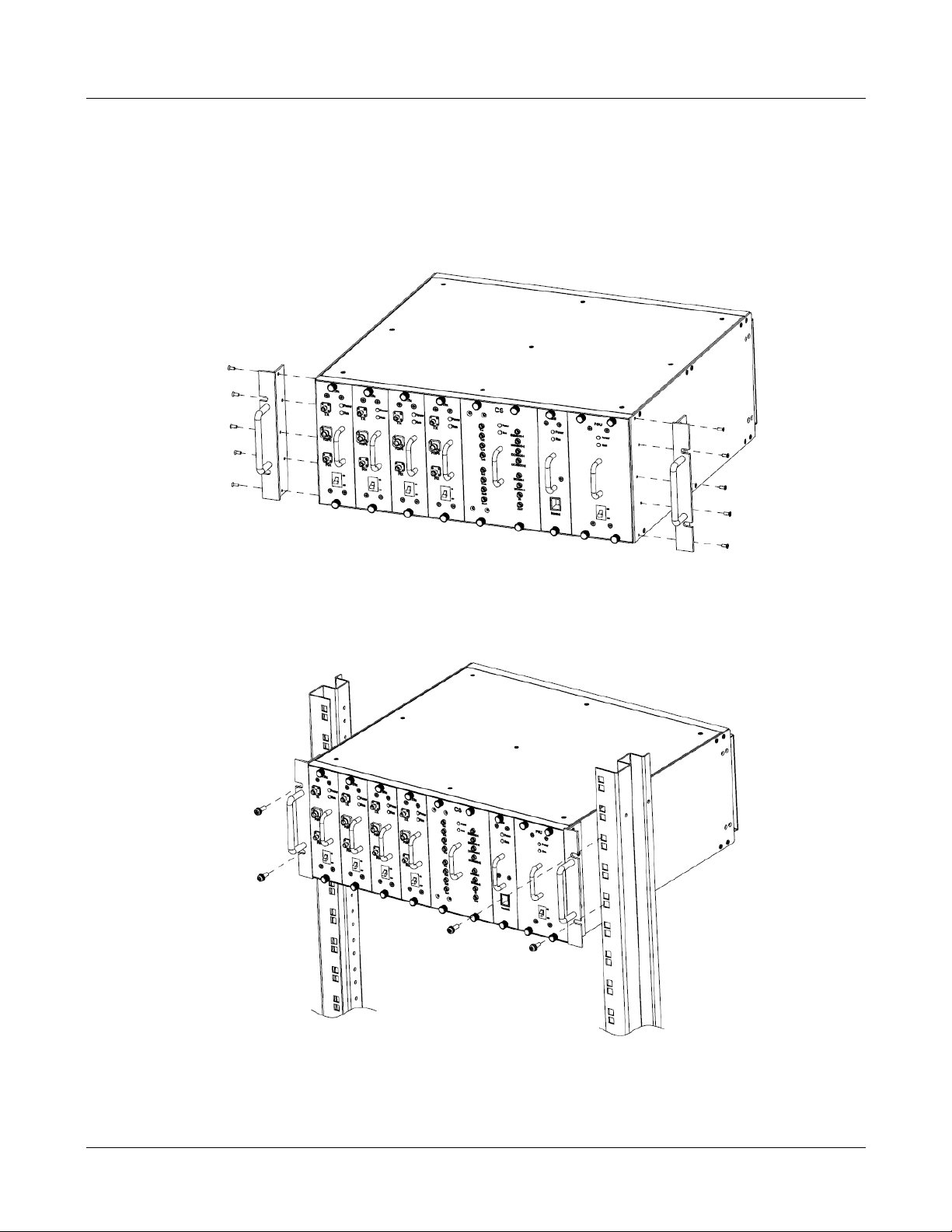
1. The Host Unit is built with mounting brack et installed for 19” rack installation.
Figure 17 Mounting Brackets for 19” Rack Installation
2. Position the host unit in the designated mounting space in the rack as shown below.
3. Secure the mounting bracket to the rack using the four mounting screws provided.
Figure 18Host Unit-19” Rack Mounting View
MBSC-C RU December 15, 2015
Page 25
Page 35
MBSC-C RU
4.3.2 Cable Connections
Note
The NEC(National Electrical Code) does not allo w signal wires t o share the same conduit with po wer wires unless the signa l
cable’s voltage range is equal to t he power wire’s voltage range.
Avoid bundling signal cable and grounding c abl e/power cable, keep them separate.
The power cable and RF inter-connection cables are supplied.
Check open and short circuits before inst alling the power cable.
4.3.2.1 Grounding
The host unit must be grounded. Do not connec t external devices to the grounding connection.
Verify the host unit is securely grounded. If it is not securely grounded, use the following procedure to
ground the host unit:
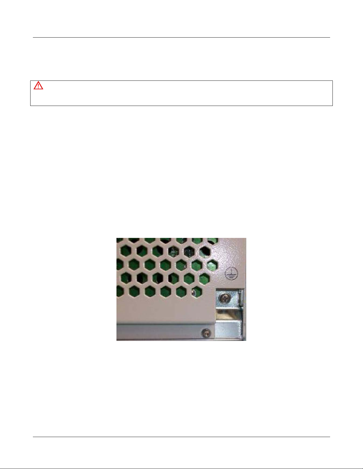
1. Find the screw at the bottom right corner of the Host Unit as shown in
Figure 19.
2. Loosen the screw located on the grounding connection.
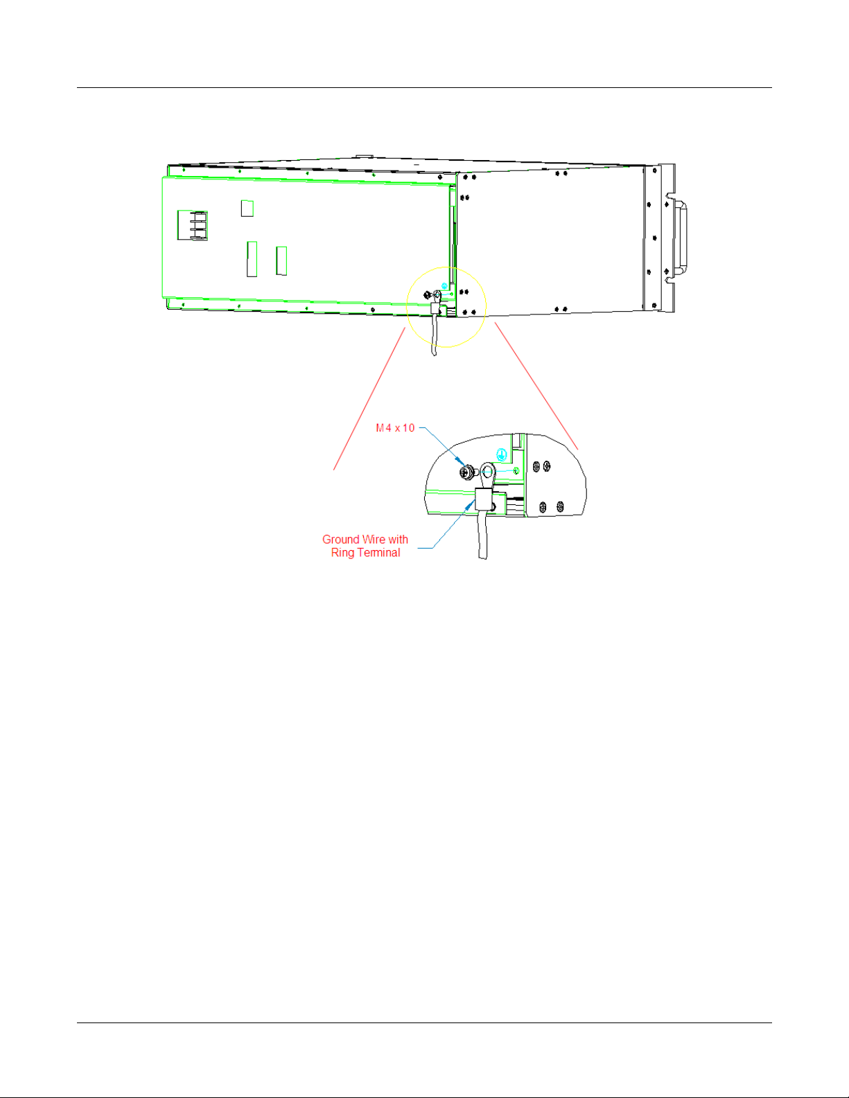
3. Connect the cabinet mounted earth-bonding cable bet ween the two lock and flat was hers as shown
Figure 20. Ensure the grounding surface is clean and free of paint, insulating material or
in
contaminants.
Figure 19Host Unit Grounding Stud
MBSC-C RU December 15, 2015
Page 26
Page 36
MBSC-C RU
Figure 20 Grounded Host Unit
4. Tighten the screw, m aking sure the cable is securely connected before movin g to the next phase of
the installation.
4.3.2.2 Coaxial Cable Connections
The RF interface between the Host Unit and the BTS (or POI) is supported through Tx/Rx QMA female
connectors mounted on the Host Unit front panel.
The Host Unit shoul d be mounted as close as possible to the BTS to minimize RF cable los ses. Use the
following steps to route and connect the simplex path coaxial cables to the Host Unit:
1. Obtain the required lengths of high performance, flexible, low loss 50Ω coaxial communication
cable for all coaxial connections.
2. Route the RF Tx and Rx path coaxial cables between the Host Unit and BTS interface and c ut to
the required length.
3. Terminate the cable with a QMA male connector.
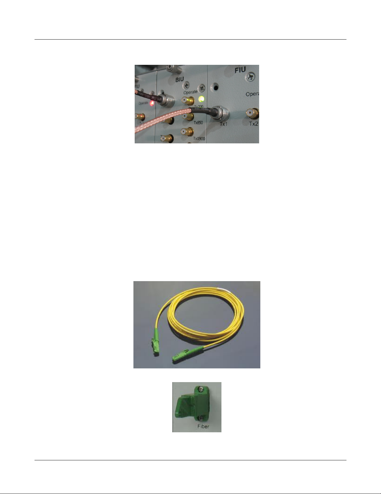
4. Connect the Tx and Rx cables from the BTS to the Tx and Rx c onnectors on the BIU front panel
corresponding to the frequency band (e.g. Tx 700, Tx 850, Tx1900, Tx 2100 or Tx2600).
MBSC-C RU December 15, 2015
Page 27
Page 37
MBSC-C RU
Figure 21 BTS QMA Coax ial Cable Connection
5. Dress and secure cable at the Host Unit.
6. The RF inter-connection between the BI U and the FIU uses QMA to QMA jumper cables supplied
with the mBSC-C equipment.
4.3.2.3 Optical Connections
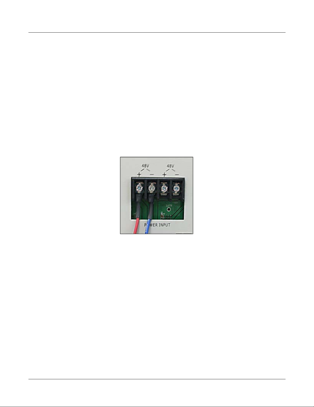
The optical interface between the Host Unit and the Remote Node is supported by an E2000/APC opti cal
adapter which is mounted on the FIU f ront panel. A single mode, E2000/APC patch cord may be used to
connect the Host Unit with Remote Node.
Use the following steps to connect the optical fibers:
1. Obtain one patch cord which is sufficient length to reach from Host Unit to t he Remot e Node.
2. Clean each patch cord connector following the patch cord supplier’s recommendation.
3. Push and secure the patch cord connector into the desired optical port on the Host Unit FIU
Figure 22Single Mode Patch Cord(E2000/APC)
Figure 23E2000 Fiber Optic Port on Host Unit FIU
4. Route the patch cords from the Host Unit to the Remote Node.
MBSC-C RU December 15, 2015
Page 28
Page 38
MBSC-C RU
5. Connect optical fiber to the Remote Node CM-BTS fiber port.
4.3.2.4 DC Power Connection
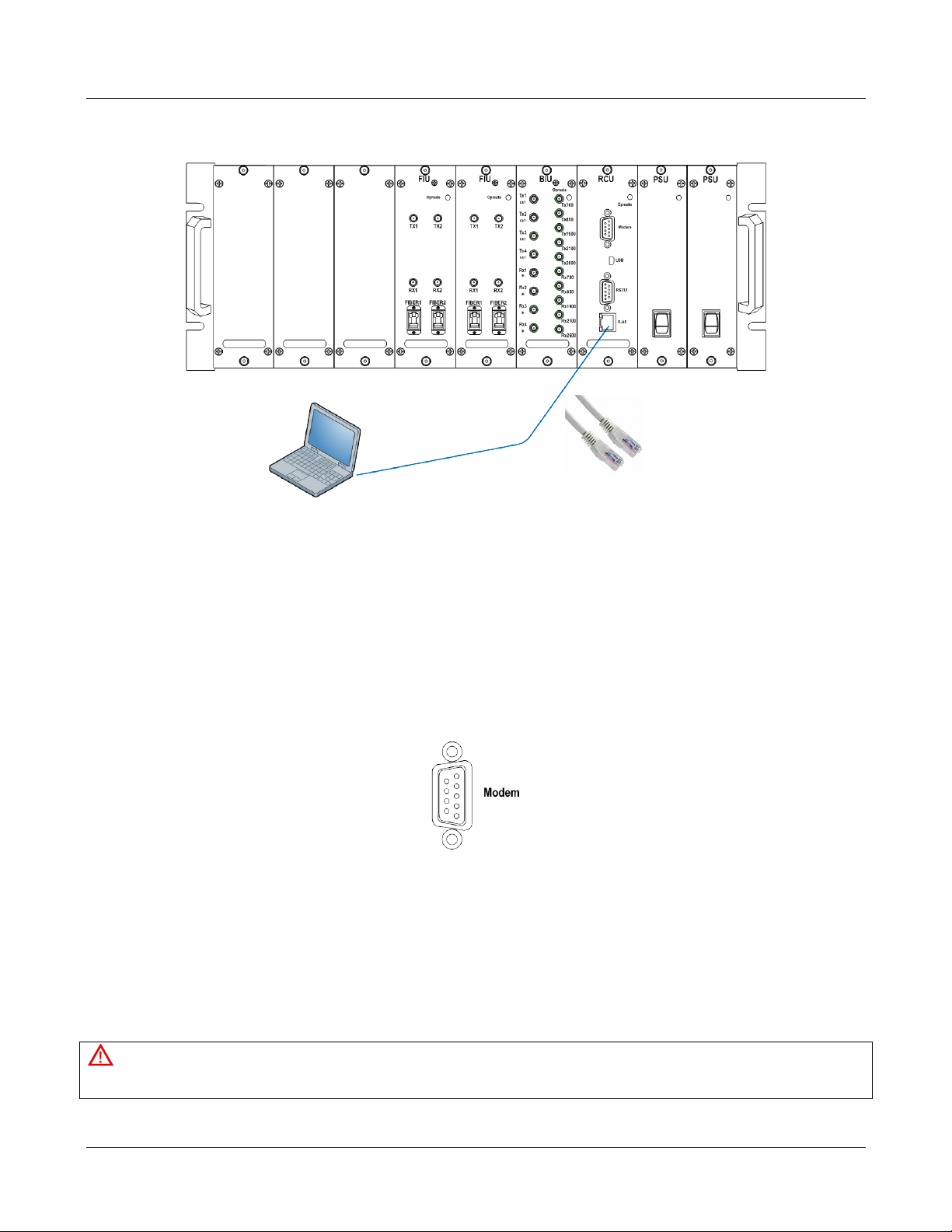
The DC power interf ace of the Host Unit is provided by a 2-wire termination located on the HU rear panel. The DC
termination provides a connection point for the power cord which is provided separately with the HU. Use the
following procedure to install the DC pow er:
1. Locate the 48 VDC power cord which is provided separately with the HU.
2. Place both HU PS module power ON/OFF switches in the OFF position.
3. Connect one end of the power cord to the DC termination on the HU.
4. Connect the other end of the power cord to the 48VDC source.
5. Dress and secure cable per standard industry practice.
Figure 2448VDC Host Power Connection
4.3.2.5 Local OMC Computer Connection
The primary communication interface betwee n the mBSC system OMC and a local computer is provided by
a single RJ45 jack on the front panel of Host Unit (note: the USB port of the RCU card can als o be used to
access the local OMC port). All the connected Remote Nodes can be monitored at the Host Unit side
through the fiber connection. The communicati on connector s upports an IP interface. A CAT5 cable is used
for connecting the local computer to the mBSC Host Unit OMC interface.
To connect the OMC computer with the Host Unit:
1. Obtain the required length of CAT5 twist ed pair cable with RJ45 connectors.
2. Route the cable between the OMC computer (or l ocal switch/router) and Host Unit.
3. Connect the cable to the RJ45jack on the front panel of Host Unit RCU.
4. Connect the other end of the cable to the RJ45 jack on the OMC computer or local switch/router.
MBSC-C RU December 15, 2015
Page 29
Page 39
MBSC-C RU
Figure 25IP Connection for local GUI Control
4.3.2.6 Modem Connection (optional)
For remote operation, the mBSC-C system provides a serial modem connecter for external modem
connection.
To connect a modem with the host unit:
1. Route the modem cable between the modem and host uni t.
2. Connect the modem cable with a DB9 female plug to the modem socket on the host unit’s RCU
front panel.
Figure 26Modem Port on RCU (DB9 male)
3. Connect the modem cable with DB9 male plug to the modem serial port.
4.4 Remote Node Installation
4.4.1 Bracket and Shroud Installation
Caution
The following high-altitude operation should be only performed by qualified personn el under well protection.
MBSC-C RU December 15, 2015
Page 30
Page 40
MBSC-C RU
1) Follow the procedures provided by the manufacturer when installing the remote unit. Do not install the unit in a place or in
a manner that does not meet the manufact urer’s specifications.
2) Use the mounting hardware supplied by the manufacturer. If non-standard mounti ng hardware is used it must meet the
requirements for mounting the unit as specified by the manufacturer.
3) Safety measures for lifting heavy materials should be follow ed to prvent injury.
NOTE: It is important that specified load limits for the unit are not exceeded as this may void the warranty.
4) High temperatures may occur due to power dissipation. Please follow the specifivations for proper remote unit ventilation
as indicated by the manufacturer.
5) Check that the mains supply is diconnected, before connecting or disconnecting the main power connector at the remote
unit.
6) Do not block airflow ventilation outlets during installation or remote unit(s) may sustain critical damage.
4.4.1.1 Install the Mounting Panel
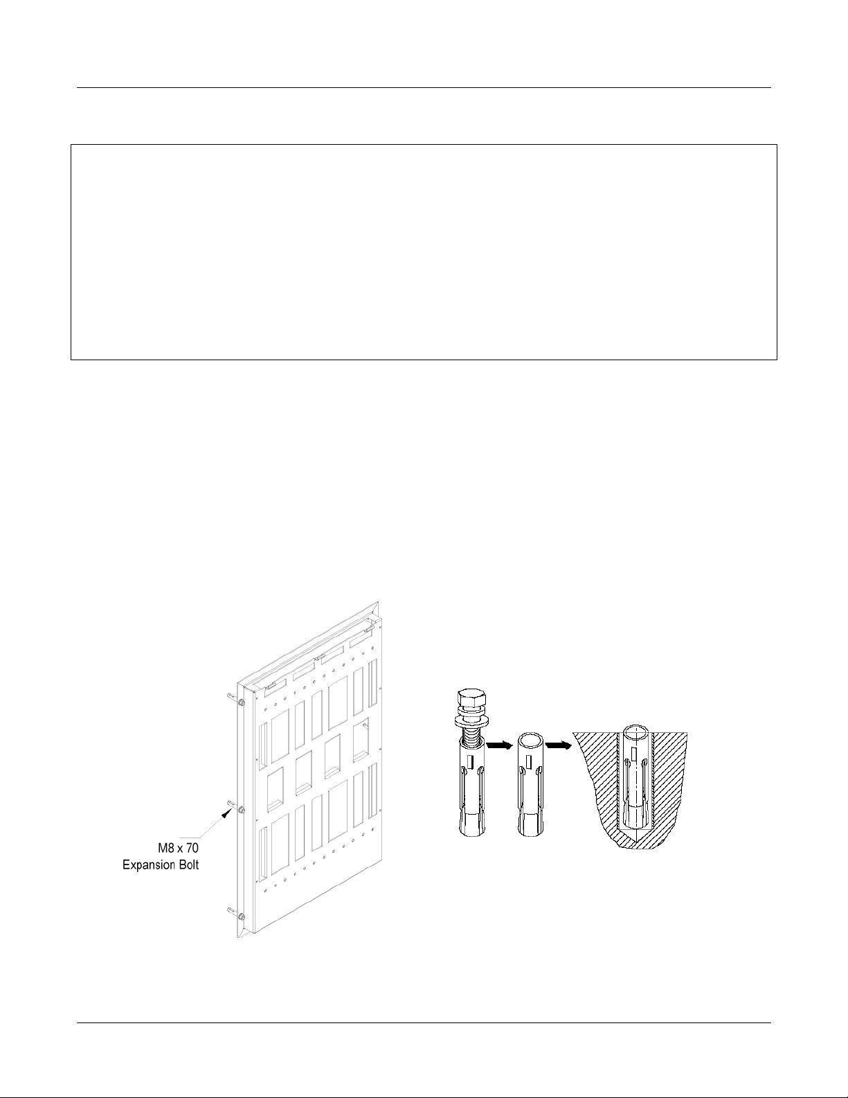
Follow the procedure below to install the mounting panel on the wall :
1. Mark the mounting panel fixing holes position on the wall.
2. Drill the holes (Ф10) on the wall.
3. Install the concrete anchors and tighten it firmly.
4. Hold the panel in the proper direction.
5. Secure the panel by using M8x70 (6pcs) expansion bolts
Bracket Mounting Installing Inflatable Bolt
Figure 27 Mounting Panel Mounting
MBSC-C RU December 15, 2015
Page 31
Page 41
MBSC-C RU
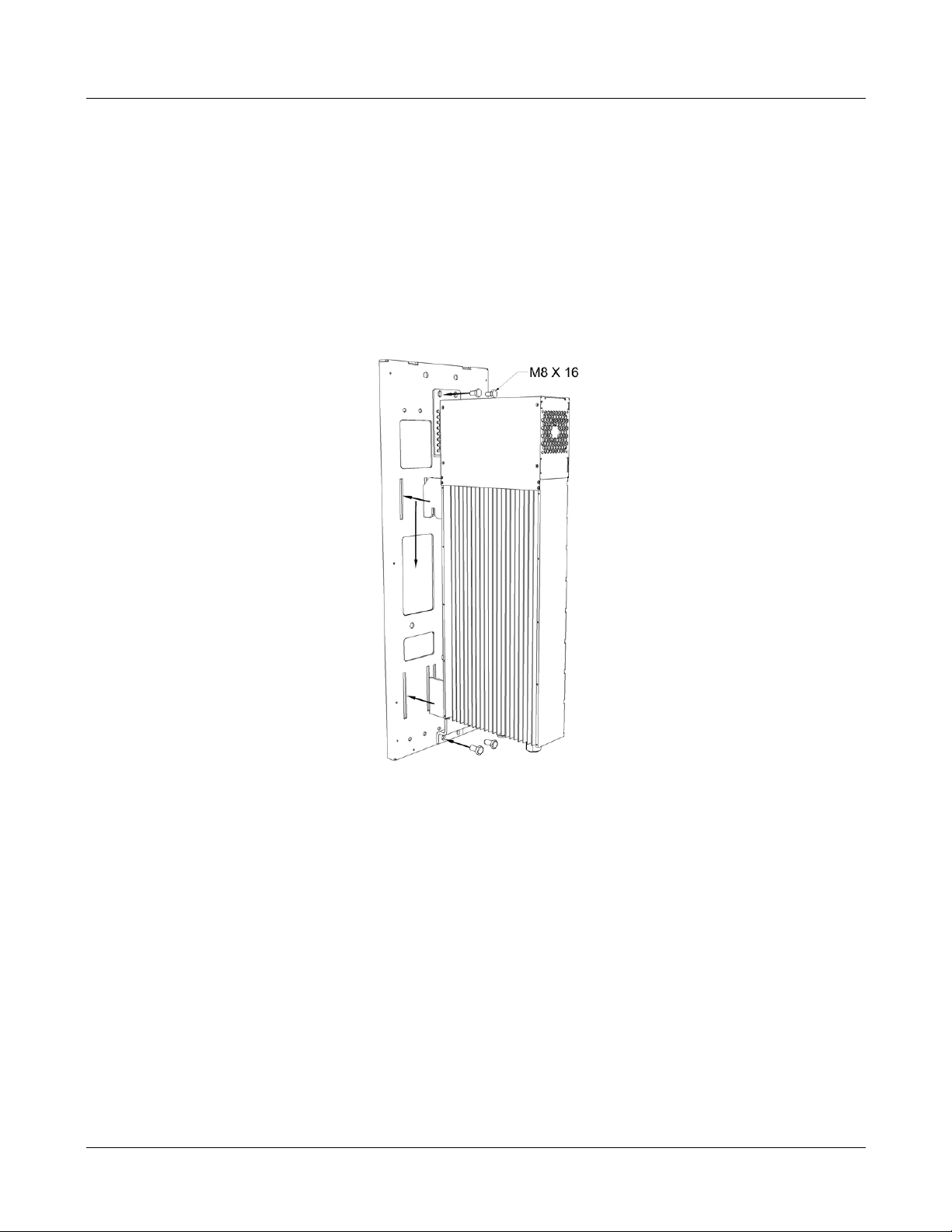
4.4.1.2 Mount the Remote Unit to the Mounting Panel
Use the following steps for a standard remote unit to mounting panel:
1. Grasp the CM-BTS/ANT or Single-band RU enclosure at the top and bottom of the casing and
carefully slide the top two hooks onto the mounting panel, followed by the lower hooks and allow the
enclosure to slide down into place.
2. After hanging the enclosure on the mounting panel, use the M8x16 screws, lock and flat washers to
secure the rear mounting bracket (top and bottom) so the unit does not move.
Figure 28Mount the Remote Unit on the Mounting Panel
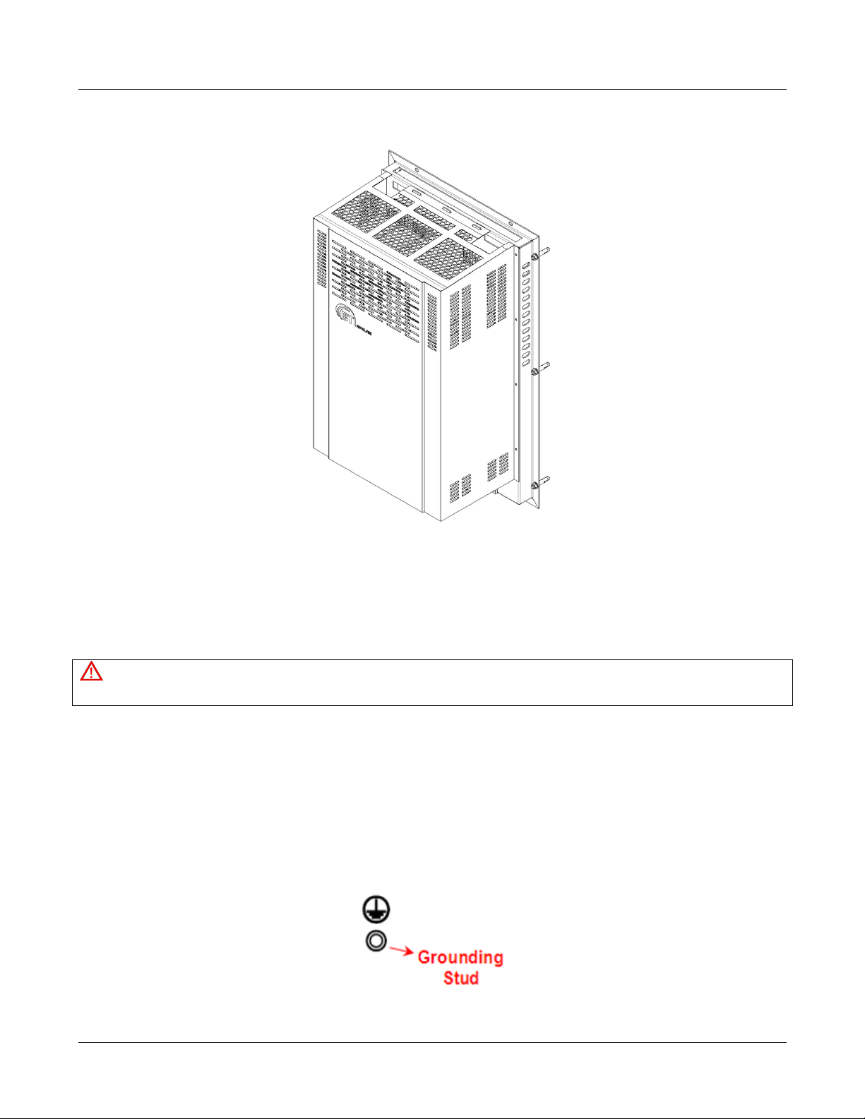
4.4.1.3 Attach the Shroud
Following is the procedure to install the shroud cover on the enclosures:
1. Line up the slots at the top of the shroud cover to the tabs at the top of the mounting panel.
2. Gently lower the slots over the tabs and slide the cover down. The cover will be at an angle.
3. Lay the cover flush against the mounting bracket, and then carefully place the M4 x 10screw
through the middle hole, aligning it to the hole on the bracket. Loosely fasten the screw. Working on
the opposite side, again place an M4 x 1 0screw through the middle hole and loosely fasten the
screw.
4. Loosely fasten the remaining M4 x 10screws to all four corners of t he cover and t hen tigh t en all t he
screws securely.
MBSC-C RU December 15, 2015
Page 32
Page 42
MBSC-C RU
Figure 29Attach the Shroud
4.4.2 Cable Connections
Attention
All the power switches must be switched off before cable installation.
Avoid bundling signal cable and grounding c abl e/power cable, keep them separate.
The power cable and RF inter-connection cables are supplied.
Check open and short circuits before installing the power cable.
4.4.2.1 Grounding
A stud is provided on the bottom of the housing of fiber CM-BTS/ANT and each single-band RU enclosure
for connecting a ground wire to the chassis, as shown inFigure 30.
Figure 30Grounding Stud
MBSC-C RU December 15, 2015
Page 33
Page 43
MBSC-C RU
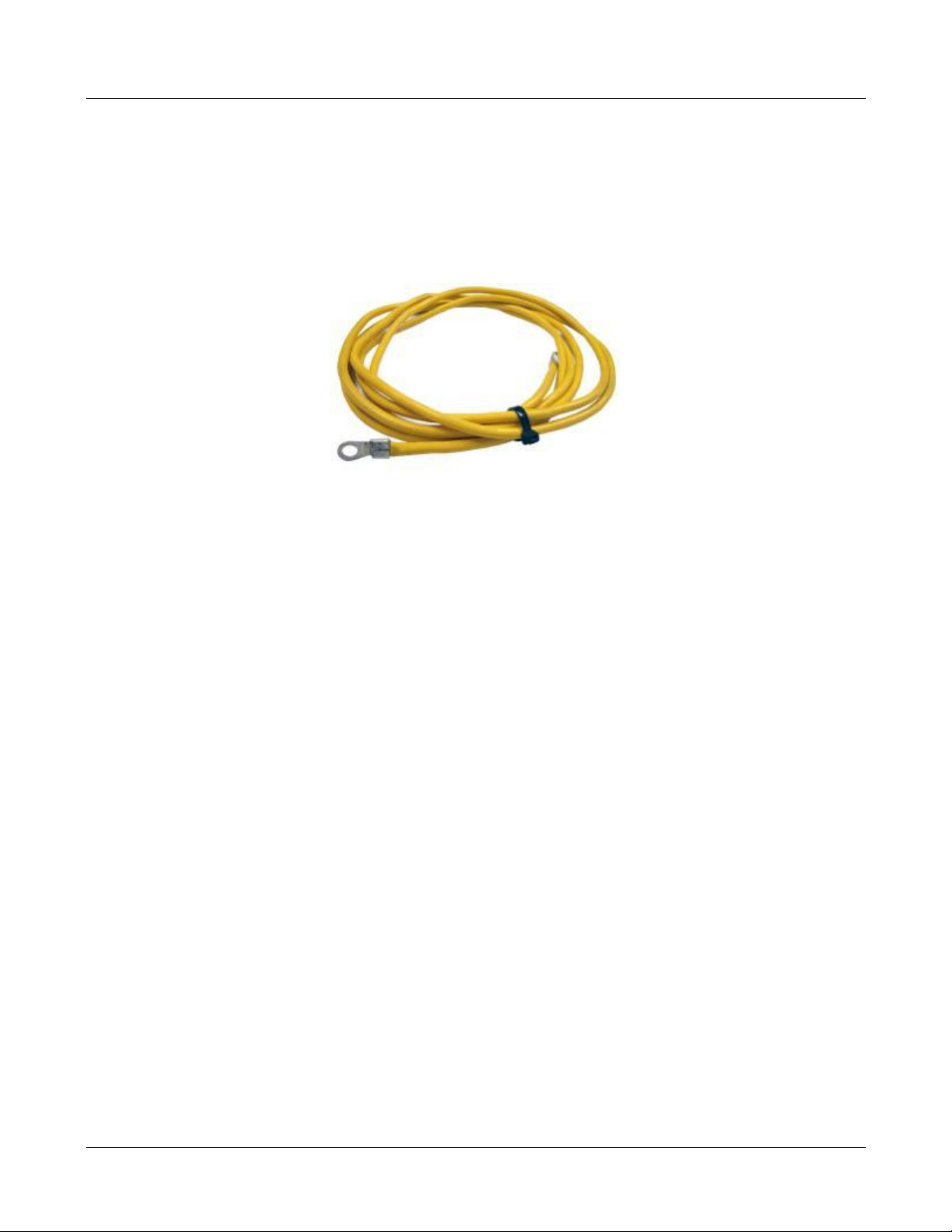
Use the following procedure to connect the grounding wire to t he cabinet and route the ground wire to an
approved earth ground source:
2
1. Obtain a length of #4 AWG(25mm
yellow-green colored copper wire as grounding wire.
2. Terminate one end of the wire with a ring terminal.
Figure 31 Grounding Wire the Ring Terminal
) and resistance lower than 0.5Ω insulated green or
3. Secure the ring end of the wire to the ground stud.
4. Route the free end of the grounding wire to an approved earth ground source.
5. Cut the chassis grounding wire to length and connect it to the approved ground source.
4.4.2.2 Coaxial Cable Connections
The simplex low-power RF interface between the fiber CM-BTS/ANT enclosure and the single-band RU
enclosures is supported through RF SMA female connectors mounted on the enclosure chassis. The duplex
high-power RF interface between th e single-band RU enclosures and the CM-BTS/ANT enclosure, and to
the service antennas, is supported through type-Nor 7/16 DIN female connectors mounted on the enclosure
chassis.
4.4.2.2.1 Fiber CM-BTS to Single-band RU
To connect the coaxial cable between fiber CM-BTS enclosure and s ingle-band RU enclosure:
1. Obtain the required lengths of high performance, flexible, low loss 50Ω coaxial communication
cable for all coaxial connections.
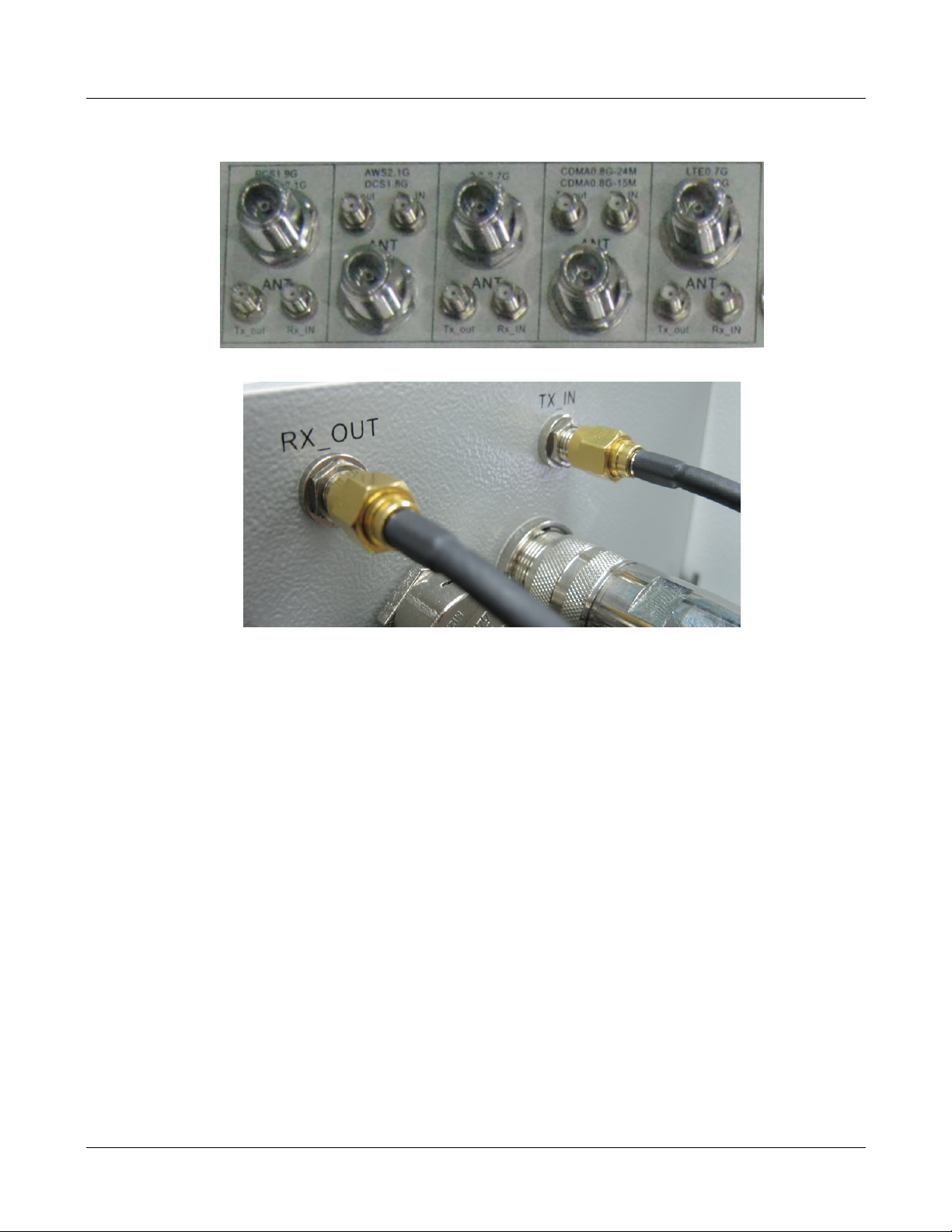
2. Route the RF Tx path and Rx path coaxial cable between the fiber CM-BTS enclosure and
single-band enclosure interface and cut to the requi red l ength.
3. Connect the Tx and Rx cable to the designated Tx and Rx connector on the chassis of fiber
CM-BTS enclosure and the chassis of the single-band enc l osure.
4. Dress and secure cable.
MBSC-C RU December 15, 2015
Page 34
Page 44
MBSC-C RU
SMA Coaxial Cable Inter-connection on Fiber CM-BTS/ANT Enclosure
SMA Coaxial Cable Inter-connection on Single-band Enclosure
Figure 32RFInter-Connect between Fiber CM-BTS and Single-band RU
4.4.2.2.2 Single-band RU to CM-ANT
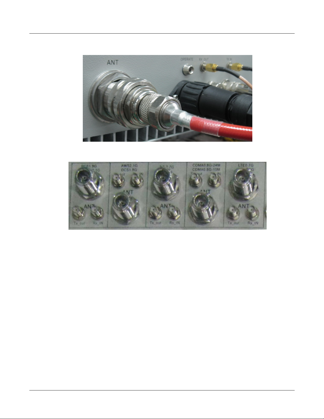
To connect the coaxial cable between CM-ANT enclosure and single-band enclosure:
1. Obtain the required lengths of high performance, flexible, low loss 50Ω coaxial communication
cable for all coaxial connections.
2. Route the RF Tx/Rx path coaxial cable between the CM-ANT enclosure and single-band enclosure
interface and cut to the required length.
3. Connect the Tx/Rx cable to the designated Tx/Rx connector on the chassis of CM-BTS/ANT
enclosure and the chassis of the single-band encl osure.
4. Dress and secure cable in the Remote Unit indoor cabinet.
MBSC-C RU December 15, 2015
Page 35
Page 45
MBSC-C RU
DIN(7/16) Coaxial Cable Inter-conn ecti on on Single-band RU Enclosure
N Type Coaxial Cable Inter-connection on CM-ANT Enclosure
Figure 33RFInter-Connect between CM-ANT and Singl e-band RU
4.4.2.3 Antenna Cable Connection
Route a coaxial antenna cable from the antenna to the equipment enclos ure. The cable must be terminat ed
with the proper connector for connecting to the ant enna port on the chassis of CM-BTS/ANT enclosure.
Below is the procedure to install the antenna cable:
1. Remove the dust cap from the N type female connector located on the chassis of the CM-BTS/ANT
enclosure.
2. Route the coaxial antenna cable to the chassis of the CM-BTS/ANT enclosure chassis.
3. Cut the antenna cable to the required length and term i nate with the proper connector.
4. Connect the antenna cable to the CM-BTS/ANT port.
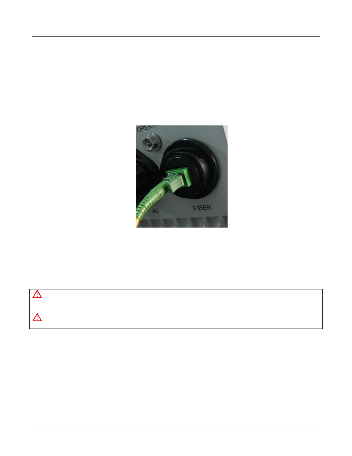
4.4.2.4 Optical Connections
The optical interface between the fiber CM-BTS enclos ure and the Host Unit is supported by duplex Tx/ Rx
optical port(s). Each optical port consists of aE2000/APC optical adapter which is mounted on the fiber
CM-BTS enclosure chassis. A single mode, E2000/APC patch cord may be used.
MBSC-C RU December 15, 2015
Page 36
Page 46
MBSC-C RU
Use the following steps to connect the optical fibers:
1. Obtain one patch cord which is sufficient length to reach from fiber optic distribution box to fiber
CM-BTS chassis.
2. Remove the dust caps the optical ports and from the patch cord connectors that will be connected.
3. Clean each patch cord connector following the patch cord supplier’s recommendation.
4. Screw-thread secures the patch cord connec tor into the optical port on the fiber optic distribution
box.
Figure 34Fiber Optic Cable Connection t o Fiber CM-BTS Enclosure
5. Route the patch cords from the fiber optic distribution box to the designated optical port on the
chassis of the fiber CM-BTS enclosure.
6. Identify each optical fiber.
4.4.2.5 AC Power Connection
Danger
Use extreme caution when work ing with high voltage A C power. Ensure all po wer is disconnected bef ore working on po wer
circuit.
Warning
Verify that the unit has been ground with an earth-bonding cable to the grounding connector.
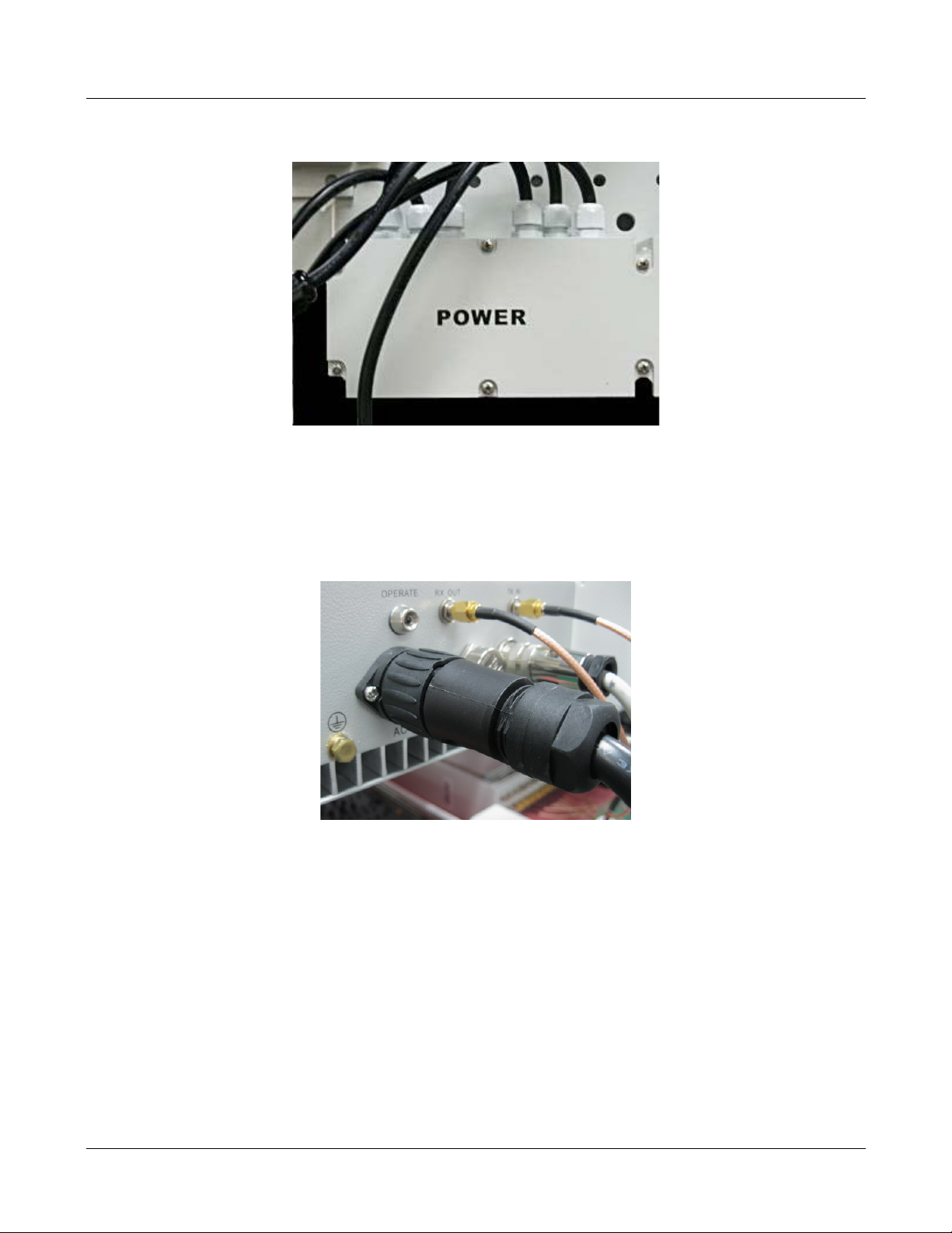
A connectorized 4-wire power cable is provided with the unit enclosures for the AC power connection, as
shown in Figure 37. The connectorized end of the power cable connects to the AC power port located on the
bottom of the enclosure.
The AC power source must supply 110/220V AC(+/20% @50/60Hz) through a 15 Amp circuit breaker. The
AC power cable provides t he wire leads for line, neutral and gro und connecti ons. The power cabl e must be
routed from the cabinet to an electrical junction box for connection to the AC power source. The power cable
is rated for indoor or outdoor use. Refer to the following procedure to install the AC power wiring:
1. Locate the AC power junct ion box which is located at the bottom of the Remote Node mounting
bracket as shown in Figure 35.
MBSC-C RU December 15, 2015
Page 37
Page 47
MBSC-C RU
Figure 35 AC Power Junction Box
2. Terminate the AC power supply wires that are required between the AC junc tion box and t he local
source of AC power.
3. For each enclosure (CM-BTS and RU) connect the short AC power cable from the AC Junction Box
to the enclosure AC power port labeled “AC”
4. Tighten the coupling nut.
Figure 364-Pin AC Power Connector
4.5 Installation Final Inspection
The following section provides a set of review procedures once the physical installation and connections are
complete. Leave the source AC power at the Host Unit and Remote Node in the OFF position (breaker open)
to prevent accidental power-up.
MBSC-C RU December 15, 2015
Page 38
Page 48
RCU
Opreate
RJ45
RS232
Modem
USB
BIU
Opreate
Tx700
Rx4
IN
Rx3
IN
Rx2
IN
Rx1
IN
Tx4
OUT
Tx3
OUT
Tx2
OUT
Tx1
OUT
Tx850
Tx1900
Tx2100
Tx2600
Rx700
Rx850
Rx1900
Rx2100
Rx2600
PSU
1
0
PSU
1
0
FIU
Opreate
FIBER2
TX2
RX2
FIBER1
TX1
RX1
FIU
Opreate
FIBER2
TX2
RX2
FIBER1
TX1
RX1
Combined RF
Rx Signals
from BTS/POI
Combined RF
Tx Signals
from BTS/POI
T
o
r
e
m
o
t
e
u
n
i
t
#
1
T
o
r
e
m
o
t
e
u
n
i
t
#
2
T
o
r
e
m
o
t
e
u
n
i
t
#
3
T
o
r
e
m
o
t
e
u
n
i
t
#
4
E
t
h
e
r
n
e
t
P
o
r
t
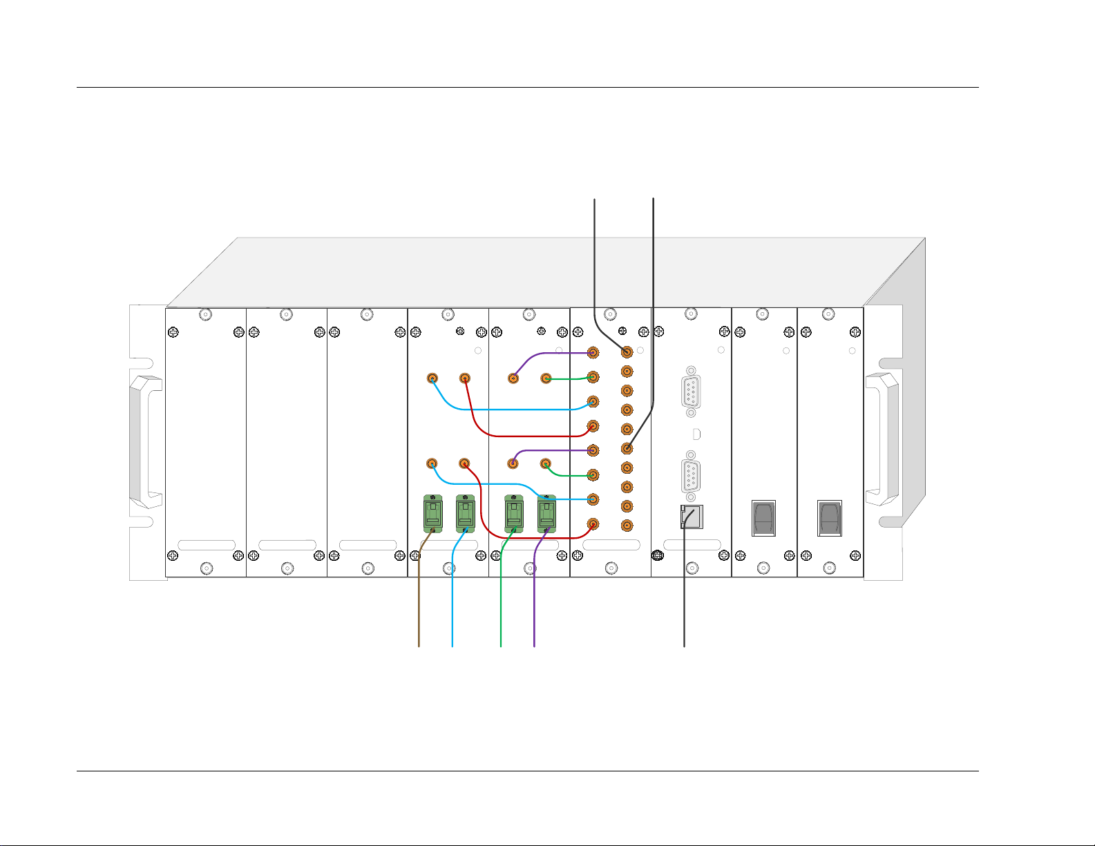
4.5.1 Host Unit Connection Overview
MBSC-C RU
Page 39
Figure 37Host Unit Connection Overview
MBSC-C RU December 15, 2015
Page 49
B
Tx_out
Rx_IN
700
A
Tx_out
Rx_IN
850
B
Tx_out
Rx_IN
2600
A
Tx_out
Rx_IN
2100
B
Tx_out
Rx_IN
1900
VENT
DEBUG
AC FIBER
TX_IN
RX_OUT
VENT
FAN
AC
RUN
ANT
TX_IN
RX_OUT
VENT
FAN
AC
RUN
ANT
TX_IN
RX_OUT
VENT
FAN
AC
RUN
ANT
TX_IN
RX_OUT
VENT
FAN
AC
RUN
ANT
CM
700MHz850MHz2600MHz
2100MHz
1900MHz
TX_IN
RX_OUT
VENT
FAN
AC
RUN
ANT
Antenna
Tx/Rx
(700~2600MHz)
Host Unit
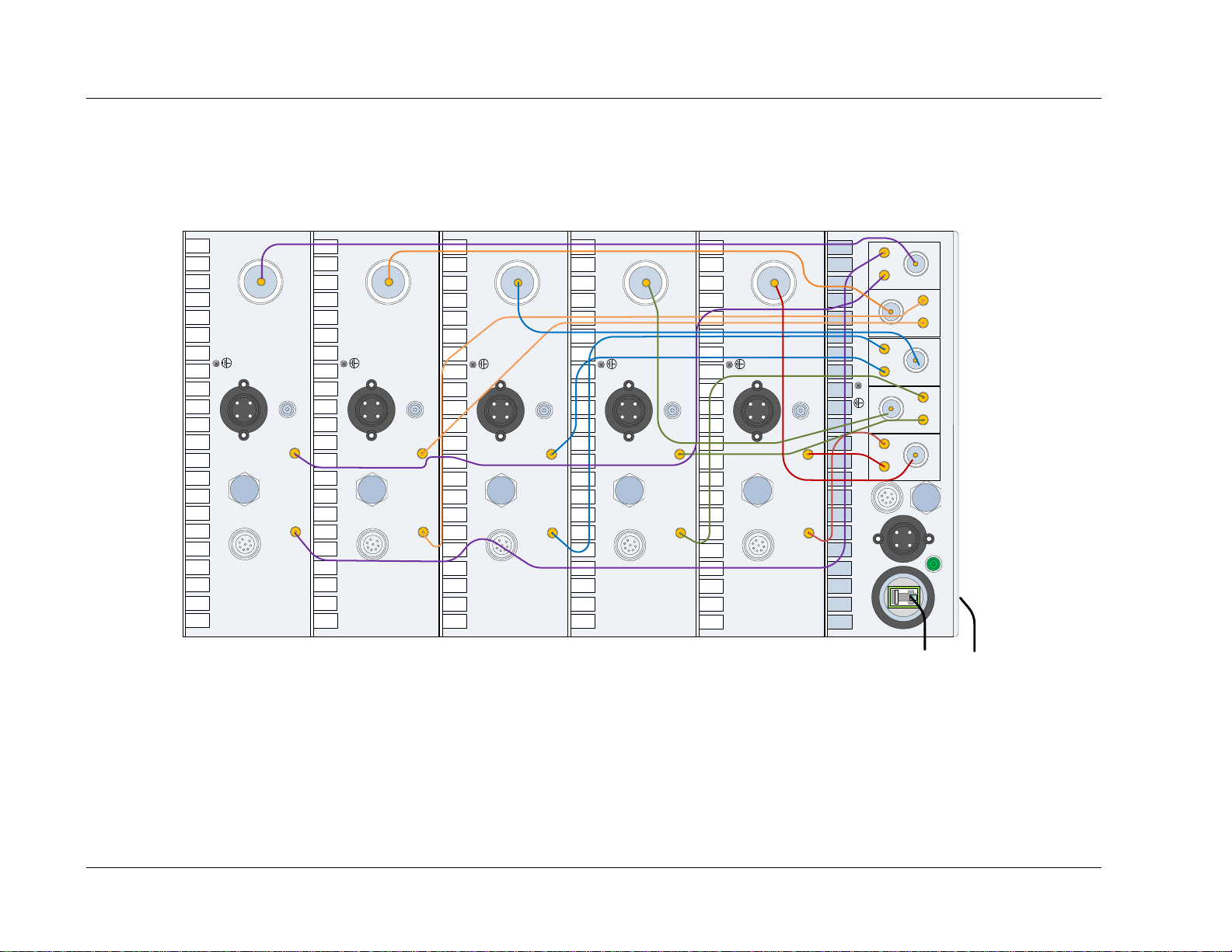
4.5.2 Remote Node Connection Overview
MBSC-C RU
Interconnection with Combiner Model FCM-CN-C
MBSC-C RU December 15, 2015
Figure 38 5-band Remote Node Inter-Connection Di agram
Page 40
Page 50

Item
Description
Screws and nuts screwed tightly, without missing flat washers and spring washers. Spring washers must be on t he
top of flat washers.
4.5.3 mBSC-C Inspection Checklist
Table 10mBSC Unit Inspection
1 Stable and normal.
2 Properly fastened
3
4 No cable damage.
5 Clean, no smudges or dust.
6 Connections between metallic parts must be reliable, to assure reliable electric connectivity.
4.5.4 Cabling Inspection
Table 11 Cable Inspection
MBSC-C RU
Item Description
1 The c onnection of the cable is tight, not loose or damaged.
2 The c abl e s hell not damaged.
3 Grounding cable is connected properly.
4 Cables ar e dressed neatly, power kept sep arate from signal.
5 The minimum bending radius of the cable is proper. (Shouldn’t be less than twenty times of the cable’s diameter.)
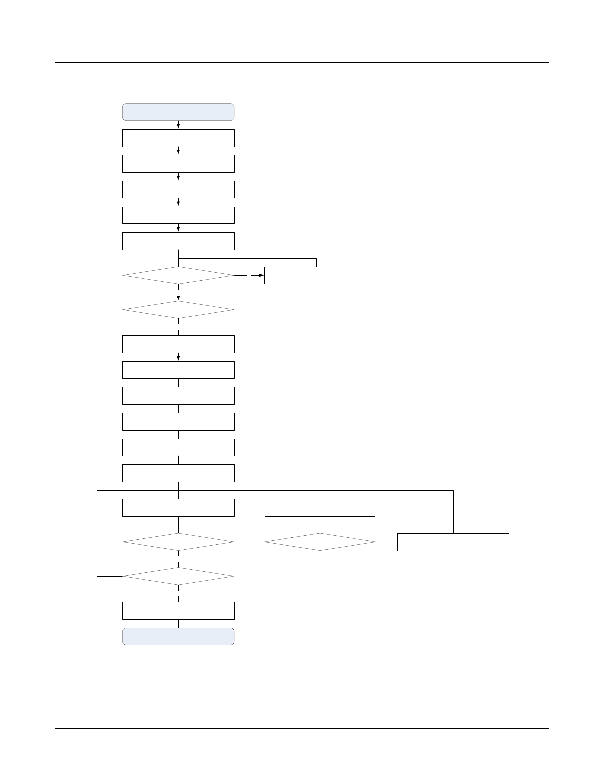
4.6 System Test
It is recommended to perform a system test after the physical installation and cabling has been ins pected
and verified.
Use the following procedure to perform the system test:
Configure the attenuation both of the forward path and reverse path
Configure the parameters of Host Unit
VSWR testing: sweep test of cables and antenna
Configure the parameters of Remote Unit
Signal testing: indoor signal level testing
Effect testing: CQT/DT testing
Coverage Optimize: based on the signal & effect testing result, adjust the mB SC parameters to
optimize the coverage
MBSC-C RU December 15, 2015
Page 41
Page 51
HU installation & configuration
Reserve path signal level evaluation
RU VSWR is normal?
HU optical power level test
RU power on
Check connection of cable & antenna
Yes
No
Test Start
Test & Debug complete
HU RF signal input/output level adjustment
RU installation, cable & antenna connection
RU optical power lever is normal
?
Yes
Reserve path pre-attenuation
RU forward path adjustment
RU reverse path adjustment
Forward path and reserve path balance
adjustment
RU parameter configuration
RU signal effect test
Coverage is normal?
Monitor & adjustment remotely
Yes
Adjust related parameters
mBSC Unit problem?
No
Yes
Adjust cable
& antenna
No
HU noise figure is normal?
Yes
No
MBSC-C RU
MBSC-C RU December 15, 2015
Figure 39 Flow Chart of System Debugging
Page 42
Page 52

MBSC-C RU
5 System Monitoring &Configuration
5.1 Accessing EMS Local GUI
The MBSC1900-040-RU system supports local conf iguration through a web-based Element M anagement
System (EMS) graphical user interface (GUI) acc essed through the RJ-45 and USB ports of the Host Unit
RCU card. The EMS local GUI is a web-based appl ication supported by standard web-browsers. Microsoft
Internet Explorer® is recommended.
System configuration and monitoring can also be performed from a remote EMS Server. The EMS Server is
a multi-user platform that includes enhanced management capabilities for configuration, monitoring and
alarming. The EMS Server is required to generate SNMP alarms.
Note:It may take up to 3 minutes for the mBSC system to initialize, therefore it is recommended to only attempt to login to the
GUI after the mBSC system has completely started, otherwise the GU I may incorrectly di splay a message indicating that the
username and/or password are wrong (when in fact they may be correct).
5.1.1 Using Ethernet Port
Access to the EMS Local GUI through an RJ-45 Ethernet connection i s provided on the RCU card in the
Host Unit shelf. The Ethernet port is the primary point of connection for the remote EMS Server. The EMS
Local GUI accessed through the Ethernet port is assigned the IP address 172.18.60.60 at the factory.
However, this IP address can be modified to suit the networking requirements of the installation (e.g. to allow
access across a Local Area Network).
Steps:
1. Obtain a CAT5 cabl e and connect it to the RJ45 port on the host unit RCU card, and connec t the
other end into the RJ45 port on the laptop/computer. Depending on the model year of your computer,
a crossover cable may be required.
2. Start an Internet Explorer browser session on the laptop/comput er, and enter the following URL to
connect to the Local GUI–“http://172.18.60.60”.
Note: The mBSC system does not provi de DHCP service. To access the GUI you will need to configure the local co mputer
with a static IP address the same subnet as the local GUI.
Note: The EMS Local GUI is a single-user interface, and supports only a s ingle user at a time. If the Ethernet interface i s
connected to a Local Area Network, and m ore than one us er is access ing the EMS Loc al GUI at t he same time, inco nsistent
operation may occur. Please use the EMS Server for multi-user applications.
MBSC-C RU December 15, 2015
Page 43
Page 53

MBSC-C RU
5.1.2 Using USB Port
Access to the EMS Local GUI through a standard USB connect ion is also available at both the Host Unit
RCU card, and the CM-BTS enclosure of the Remote Node. The EMS Local GUI has a fixed IP address
assignment when accessed through the USB port – it is set at the factory and cannot be changed.
Steps:
1. Install the USB-Ethernet driver on the laptop/computer. The laptop/computer must be connected
to the internet in order for the drivers to be automati cally installed.
2. Obtain a USB cable and connect it to the USB port on the host unit and the laptop/comput er.
3. Start an Internet Explorer browser session on the laptop/computer, and enter the following
URL–“http://192.168.5.220”.
Note: The mBSC s ystem does not provide DHCP servic e. To access the GUI you may need to configure the local computer
with a static IP address the same subnet as the local G U I.
MBSC-C RU December 15, 2015
Page 44
Page 54
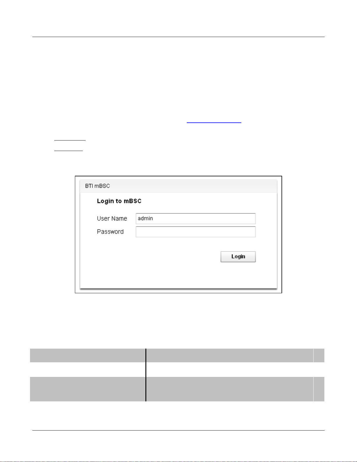
MBSC-C RU
5.1.3 Login to EMS Local GUI
Access the EMS Local GUI as follows:
1. Type the appropriate URL into the browser (e.g. http://192.168.5.220 for USB port). The dialog bo x
shown in Figure 40– EMS Local GUI Login will appear.
2. User name: Type in the user name provided for you to access the system (default = “admin”)
3. Password: Type in the password provided for you to access the syst em (def aul t = “”)
4. Click Login
Figure 40– EMS Local GUI Login
The default user account for the EMS Local GUI is set at the factory as follows:
Table 12Local GUI Default User Accounts
Username
Password
Access Control Level
Admin
(null)
Equipment properties view
Gain setting
The mBSC system administrator may have created different usernames and passwords for you to use.
MBSC-C RU December 15, 2015
Page 45
Page 55
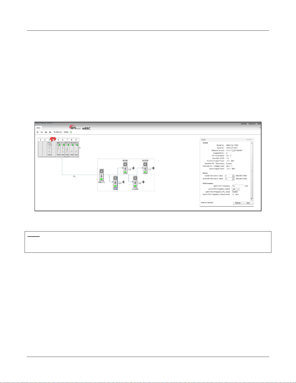
MBSC-C RU
5.2 Navigating the EMS Local GUI
When logged in to the EMS Local GUI, it displays the main page as shown in Figure 41. On the left side of
the main page the topology of the mBSC-C system you are connected to is automatically displayed. This
includes the Host Unit and the fiber attached Remote Nodes. On the right side is a floating window for
displaying system component properties.
Figure 41- Main Page Expanded Topology
Note: The EMS Local GUI will only display the nodes that are connected to the specific Host Unit shelf that you are connected
to. If the site has multiple Host Unit shelves (to support many Remote Nodes) then you will need to separately connect to each
shelf to perform configuration. T he EMS Server, if provided, will enable connect ions to multiple c onnected Host Unit Shelves
and multiple installation sites.
In the topology window the system can be placed into a summary view by d ouble-click ing on the Host Unit
shelf, or the Remote Node components.
MBSC-C RU December 15, 2015
Page 46
Page 56
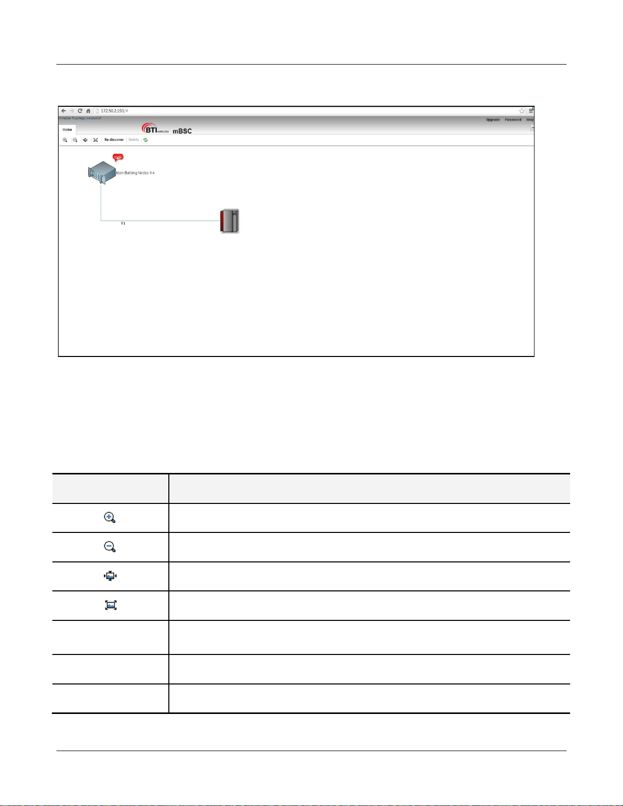
MBSC-C RU
Figure 42- Main Page Summary View
5.2.1 Topology Tool Bar
Various functions can be performed by clicking on the following icons.
Table 13 Tool Bar Functions
Tool Function
Re-discover
Zoom in – Zooms in the topology diagram
Zoom out – Zooms out the topology diagram
Reset – Resets the topology vie w to default
Overview – Resizes topology diagram to full screen
Re-Discovery – Constructs the topology upon initial local GUI login or changes in system
configuration. This function is c r ucial to make sure topology structure i s correct.
Delete Delete – Deletes a component from the Topology view
Refresh Refresh – Refreshes “real time” system topology
MBSC-C RU December 15, 2015
Page 47
Page 57

5.2.2 Upgrade/Password Functions
The links in the upper right corner contain the Upgrade, Password, and Help functions.
Table 14 General GUI T ools
Function Description
Upgrade Perform a c omponent software upgrade
Password Change the login password for current User
Help System information and Help
MBSC-C RU
5.3 Installation & Configuration
5.3.1 Network & Communications
5.3.1.1 Change IP Address of RCU Ethernet port
In order to connect the RCU to a Local Area Net work (for example, to allow remote access t o the mBSC
from outside the Site) the user will need to chang e the IP address to the address required in their e xisting
network.
To change the IP address of the RCU E thernet Port:
1. Click on the RCU in the topology diagram and the component window will pop up on the right as
shown in Figure 43- RCU Component View.
2. Locate the required fields and set the appropriate values.
a. Mode of Communication: must be set to Ethernet
b. Equipment IP Address: enter the valu e assigned to this HU shelf
c. Equipment Subnet Mask: enter app ropriate subnet mask
d. Equipment Default gateway: enter assigned gateway
3. Click Save
MBSC-C RU December 15, 2015
Page 48
Page 58
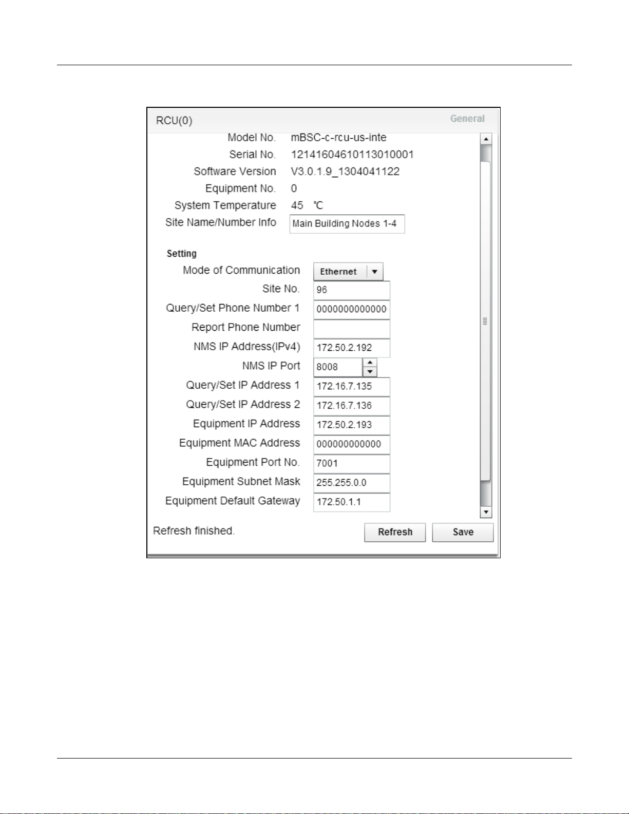
MBSC-C RU
Figure 43- RCU Component View
5.3.1.2 Assign IP Address for Remote EMS Server
The mBSC-C system can also be managed from a remote EMS Server. To communicate wit h the remote
server the IP address must be reachable form the local network, and must be configured within the RCU.
To assign the IP address of the remote EMS Server:
1. Click on the RCU in the topology diagram and the component window will pop up on the right as
shown in Figure 43- RCU Component View.
MBSC-C RU December 15, 2015
Page 49
Page 59

MBSC-C RU
2. Locate the required fields and set the appropriate values.
a. NMS IP Address(IP4): enter the val ue assigned to the remote EMS Server
b. NMS IP Port: enter port (default value is 8008)
c. Equipment Default gateway: enter assigned gateway
3. Click Save
5.3.1.3 Assign HU Site Name/Number
Users can create a name or a site number for the Host Unit. This information is displayed in the Summary
View (Figure 43- Main Page Summ ary View), or is used in the EMS Server to dis tinguish between multipl e
Host Shelves and/or multiple mBSC systems .
To assign the HU Site name/Number:
1. Click on the RCU in the topology diagram and the component window will pop up on the right as
shown in Figure 43- RCU Component View.
2. Locate the required fields and set the appropriate values:
a. Site Name/Number Info: enter the desired identifier
3. Click Save
5.3.2 System Installation
5.3.2.1 Verify Component Status
Once the system has been properly installed, check the status of each component in the Home tab, as
shown in Figure 44- Main Page Equipment Status.
MBSC-C RU December 15, 2015
Page 50
Page 60
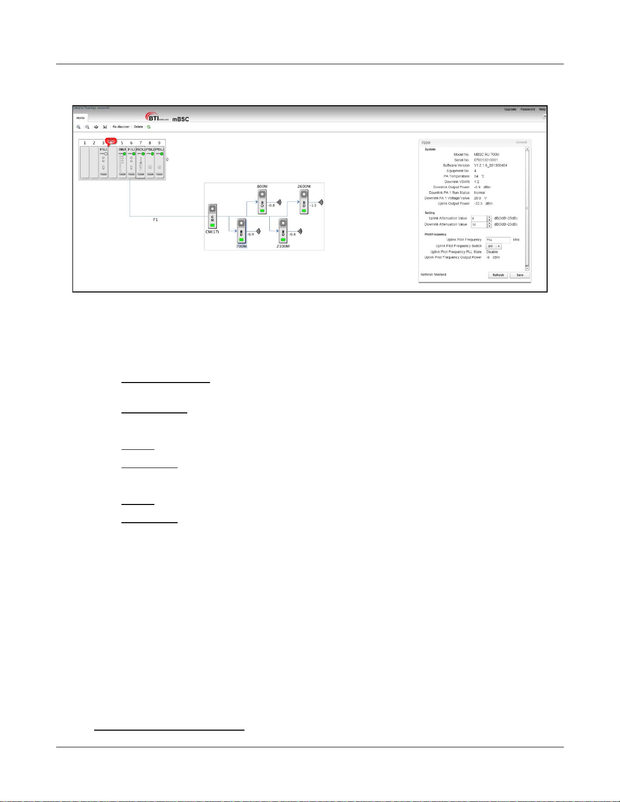
MBSC-C RU
Figure 44- Main Page Equipment Status
Check the current status of each component as follows:
1. Update Topology view:
a. Click Re-Discover: If new equipment (eg. Remote Node) has been added but does not yet
show up in the topology view
b. Click Refresh: If all components appear and to ensure current status is reflected
2. Review HU status indicators:
a. All OK: Component LEDs in the HU shelf indicate green state
b. Error/alarm: Component LEDs are flashing red, and a red “balloon” is present
3. Review Remote Node status indicators:
a. All OK: Component LEDs in the Remote Node indicate green state
b. Error/alarm: Component LEDs are flashing red, and a red “balloon” is present
If components appear with error conditions please see sections 5.3.3.1Optical Link Alarms and 5.5
Monitoring for details on error conditions.
5.3.2.2 Verify Optical Power Levels
The optical power levels at both ends of the fiber link (at the FIU of the Host Unit, and the CM of the Remote
Node) can be observed and verified through the EMS Local GUI.
Check optical power levels at the Host Unit as fol l ows:
1. Click on the FIU in the topology diagram and the component windo w will pop up on the right as
shown in Figure 45- FIU Optical Power Levels .
2. Optical Transceiver 1 Tx Power: the output power of the FIU 1 to the fiber.
MBSC-C RU December 15, 2015
Page 51
Page 61
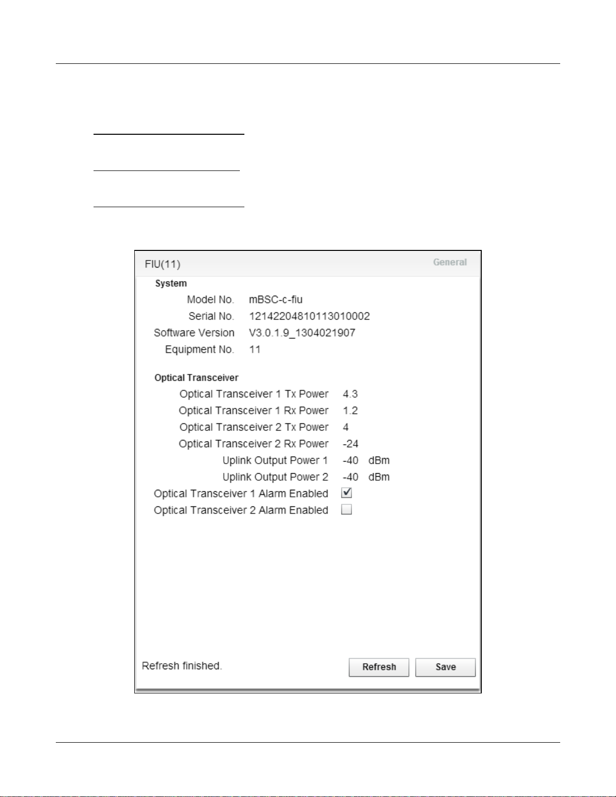
a. Nominal value is: +4.0 dBm +/-1.5 dB (impacted by temperature)
3. Optical Transceiver 1 Rx Power: the input power of the FIU 1 from the fiber.
a. Acceptable range is:-15 dBm ~ +6dBm (impacted by fiber loss)
4. Optical Transceiver 2Tx Power: the output power of the FIU 2 to the fiber.
a. Nominal value is: +4.0 dBm +/-1.5 dB (impacted by temperature)
5. Optical Transceiver 2 Rx Power: the input power of the FIU 2 from the fiber.
a. Acceptable range is: -15 dBm ~ +6dBm (impacted by fiber loss)
MBSC-C RU
Figure 45- FIU Optical Power Levels
MBSC-C RU December 15, 2015
Page 52
Page 62
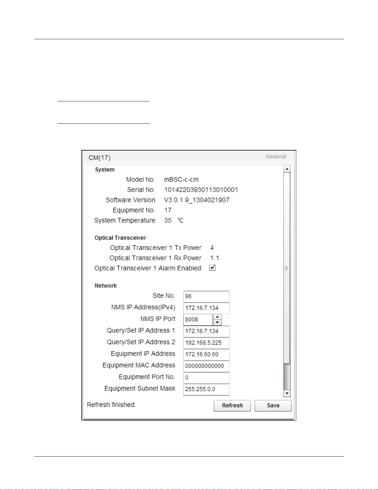
MBSC-C RU
Check optical power levels at the Remote Node as f ol lows:
1. Click on the CM in the topology diagram and the component window will pop up on the right as
shown in Figure 46- CM Optical Power Levels.
2. Optical Transceiver 1 Tx Power: the output power of the CM 1 to the fiber.
a. Nominal value is: +4.0 dBm +/-1.5 dB (impacted by temperature)
3. Optical Transceiver 1 Rx Power: the input power of the CM from the fiber.
a. Acceptable range is: -15 dBm ~ +6dBm (impacted by fiber loss)
Figure 46- CM Optical Power Levels
MBSC-C RU December 15, 2015
Page 53
Page 63
5.3.2.3 Verify Software Versions
Click on Help in the upper right corner to verify the software version of the EMS Local GUI.
MBSC-C RU
Figure 47 - EMS Local GUI Software Version
To verify the s oftware version installed on each component click on the Upgrade button in the top right:
MBSC-C RU December 15, 2015
Page 54
Page 64
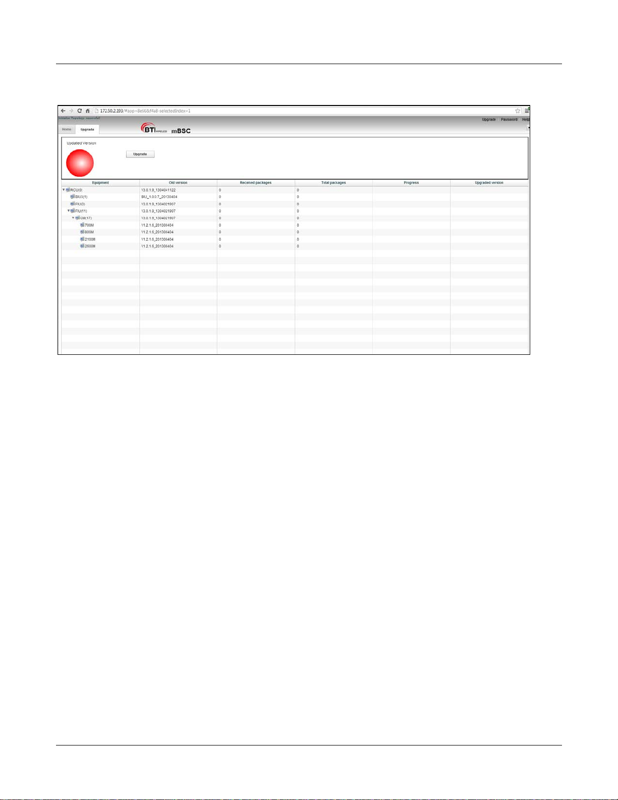
MBSC-C RU
Figure 48 - Component Software Versions
5.3.3 Alarms
5.3.3.1 Optical Link Alarms
Optical Link alarms at the FIU will occur for various reasons:
1. Remote Node not in service: The Remote Node connected to the specific FIU link is not yet powered
up
2. Remote Node malfunctioning: connected to the specific FIU link is in an error state
3. Fiber issue: The fiber link between the specific FIU and the Remote Node has excessive loss
(possibly due to breakage or to dirty optical c onnectors)
4. No Remote Node: there is no plan to connect a Remote Node to the FIU (an FIU card supports t wo
links and one link is not used in this system).
In Figure 41- Main Page Expanded Topology the FIU in slot 3 is indicating an alarm state. Note the following
in Figure 49 – Optical Link Alarms:
1. The LED indicator for the FIU in slot 3 is not solid Green
a. A flashing red state indicates an alarm
2. There is a red “balloon” extending from the FIU in slot 3
MBSC-C RU December 15, 2015
Page 55
Page 65
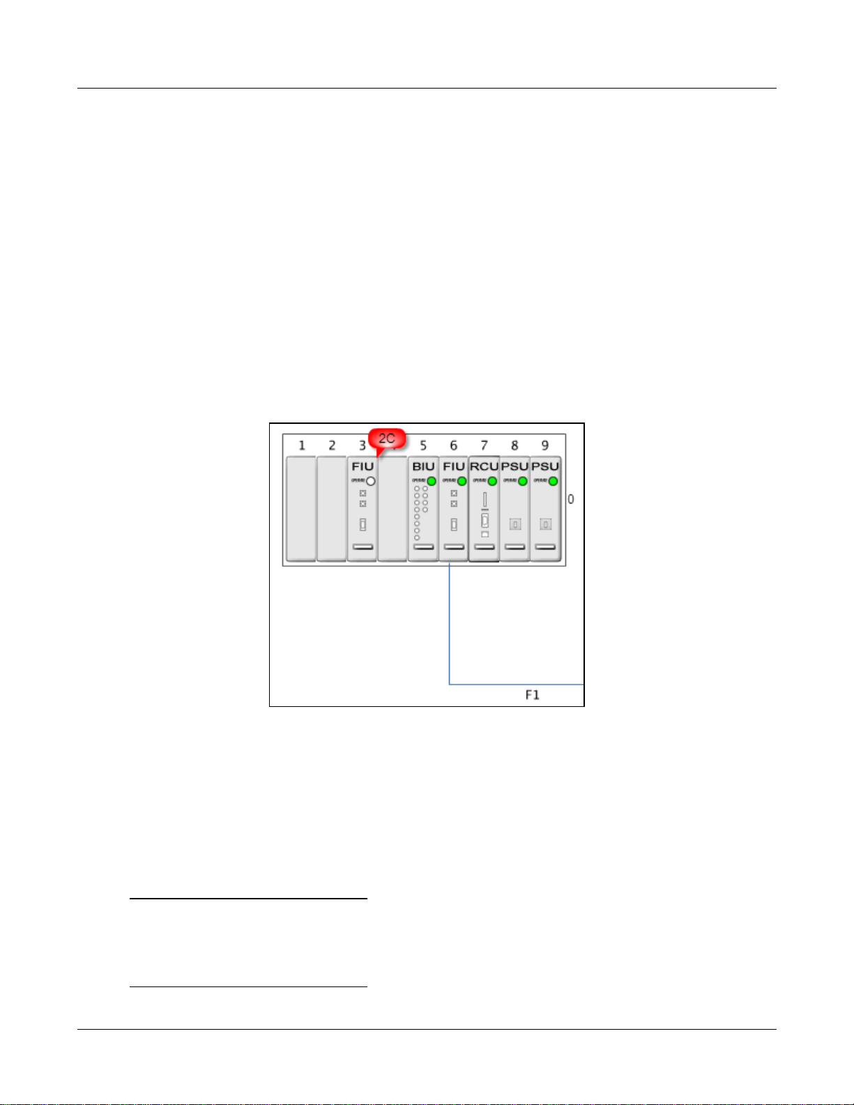
MBSC-C RU
a. The FIU supports two fiber connections: 1C indicates 1 alarm condition exist s, 2C indicates 2
alarm conditions exist
3. There are no remote Nodes connected to the FIU in slot 3, and no fiber are extending from the FIU
a. In this case the HU recognizes there are no Remote Nodes connected
4. The FIU in Slot 6 is showing green operational status
a. No alarms are being reported, yet there is only one fiber extending f rom the F IU i n conne c tion
F1
b. Normally this FIU would report an alarm state for F2 (“1C” showing in the red al arm balloon)
c. No alarm state is shown because the user disabled Optical Transceiver 2 Alarms
Figure 49 – Optical Link Alarms
To disable optical transceiver alarms:
1. Click on the desired FIU in the topology window. The FIU com ponent dialog box will appear as in
Figure 45- FIU Optical Power Levels
2. Optical transceiver 1 Alarm Enabled:
a. To enable alarms place a “check” in the box
b. To disable alarms clear the box
3. Optical transceiver 2 Alarm Enabled:
a. To enable alarms place a “check” in the box
MBSC-C RU December 15, 2015
Page 56
Page 66

MBSC-C RU
b. To disable alarms clear the box
4. Click Save
5.3.3.2 Enable SNMP alarms
Support for SNMP in the mBSC-C system is provided through the remote EMS Server. For more information
about support for SNMP please refer to UM-MBSC-C-EMS.
5.4 System Tuning
5.4.1 BTS Signal Conditioning
The interface from the operator BTS equipment to the MBSC1900-040-RU is via simplex RF connections to
the BIU. The nominal downlink input to the BIU (TXin) is 0 dBm±1dB (range: -10dBm to +10dBm). If the BTS
signal downlink exceeds +10 dBm, or the signal is a composite duplex RF signal, then RF signal
conditioning will be required.
BTI provides a high-power Point of Interface to perform RF signal c onditioning (mB SC-C-POI) T he use and
operation of this component is outside the scope of thi s document.
5.4.2 Set Downlink Gain
It may be necessary to adjust the Downlink gain of the mBSC-C system in order to achieve a balanced
forward and reverse link, or to adjust for other conditions (input levels from the BTS, propagation
characteristics at different bands, specific RF design). The MBSC1900-040-RU provides two points of
adjustment for downlink gain:
1. Software controlled attenuator for each band in the BIU
2. Software controlled attenuator in each band-specific Remote Uni t
The determination of appropriate values f or these parameters is outside the scope of this document.
5.4.2.1 Adjust BIU Downlink Attenuator
Adjust the BIU downlink value for each frequency band as follows:
1. Click on the BIU in the topology diagram and the com ponent window will pops up on the right as
shown in Figure 50 - BIU Attenuator.
2. Downlink Attenuation Value (XXX MHz): Input the appropriate value for each frequency band (0dB –
25dB range)
3. Click Save
MBSC-C RU December 15, 2015
Page 57
Page 67
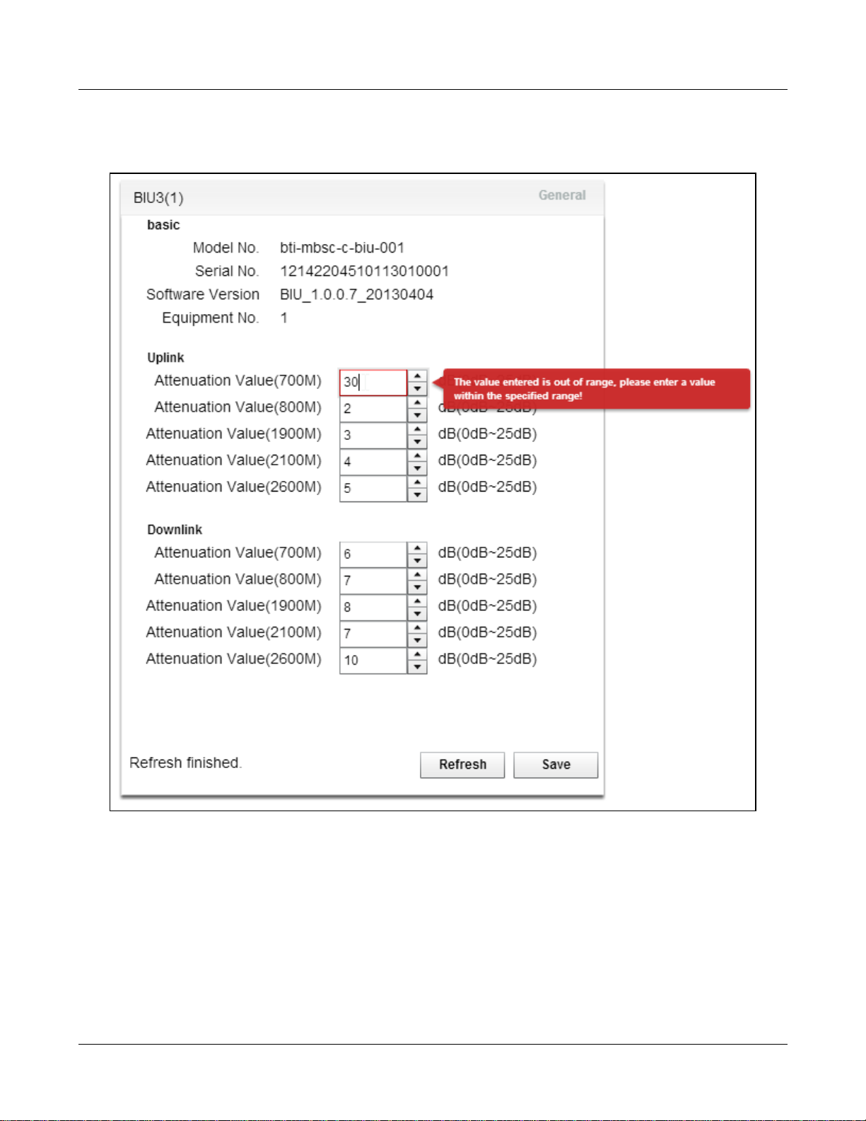
Note that the system will report an error message if the input value is out of range.
MBSC-C RU
Figure 50 - BIU Attenuator
MBSC-C RU December 15, 2015
Page 58
Page 68

MBSC-C RU
5.4.2.2 Adjust RU Downlink Attenuator
Adjust the RU downlink value for the specific RU / frequ ency band as follows:
1. Click on the RU in the topology diagram and the component window will pops up on the right as
shown in Figure 51 - RU Attenuator.
2. Downlink Attenuation V alue: Input the appropriate values (0dB – 25dB range )
3. Click Save
MBSC-C RU December 15, 2015
Page 59
Page 69
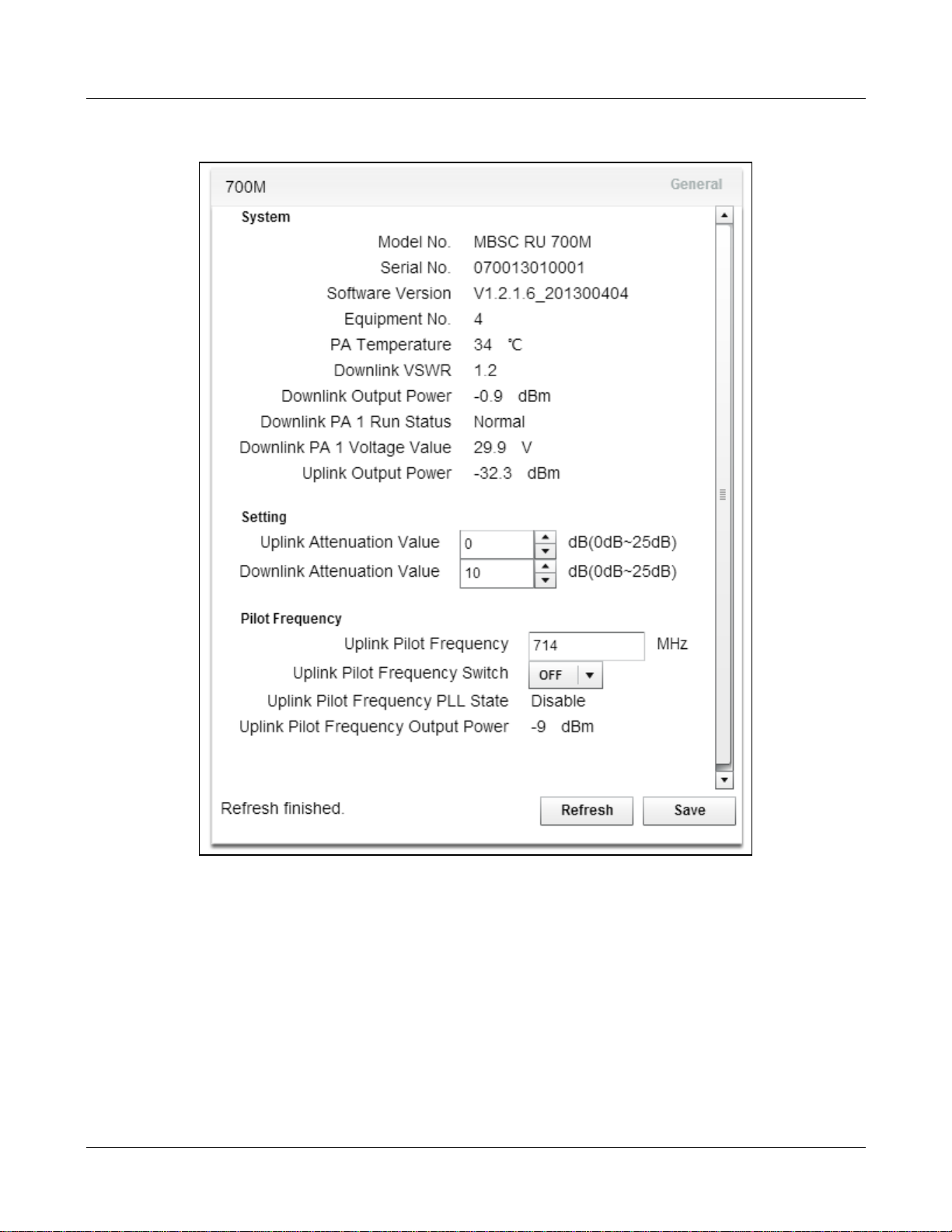
MBSC-C RU
Figure 51 - RU Attenuator
5.4.3 Set Uplink Gain
It may be necessary to adjust the Uplink gain of the mBSC-C system in order to achieve a balanced forward
and reverse link, or to adjust for other conditions (antenna placement, dynamic range requirements,
propagation characteristics at different bands, specifi c RF design). The MBSC1900-040-RU provid es two
points of adjustment for uplink gain:
1. Software controlled attenuator for each band in the BIU
2. Software controlled attenuator in each band-specific Remote Uni t
MBSC-C RU December 15, 2015
Page 60
Page 70

MBSC-C RU
The determination of appropriate values f or these parameters is outside the scope of this document.
5.4.3.1 Adjust BIU Uplink Attenuator
Adjust the BIU uplink attenuation value for eac h frequency band as follows:
1. Click on the BIU in the topology diagram and the com ponent window will pops up on the right as
shown in Figure 50 - BIU Attenuator.
2. Uplink Attenuation Value (XXX MHz): Input the appropriate val ue for each frequency band (0dB –
25dB range)
3. Click Save
5.4.3.2 Adjust RU Uplink Attenuator
Adjust the RU uplink attenuation value for the s pecific RU / frequency band as follows:
1. Click on the RU in the topology diagram and the component window will pops up on the right as
shown in Figure 51 - RU Attenuator.
2. Uplink Attenuation V alue: Input the appropriate values (0dB – 25dB range)
3. Click Save
MBSC-C RU December 15, 2015
Page 61
Page 71

MBSC-C RU
5.4.4 Link Verification
The MBSC1900-040-RU sys tem is equipped with features that enable the downlink and uplink link to be
fine-tuned from the head-end location using c ommon test equipment (RF signal generator and RF power
detector).
5.4.4.1 Verify End-to-End Downlink Gain
Each RU in the remote node is equipped with a calibrated D ownlink Power Detector which wi ll display the
average power at the output of the RU. By injecting an RF CW signal at each TXin port of the BIU the
end-to-end downlink system gain can be verified without addit ional test equipment required at the Remot e
Node.
Verify the end-to-end Downlink Gain for each frequency band as follows:
1. Using an RF Signal generator inject a CW RF signal to the TXin port of the BIU
a. Set the frequency to the center of the spectrum to be used in the system (if the operator
licensed bands are not known set the frequency to center of t he band – e.g. 2132.5 MHz for
AWS band)
b. Set the input RF power level to be 3 – 5 dB below the expected RF level to product maxim um
output power at the RU to avoid accidental overdrive (e.g. if the gain is set so that 0dBm
input will produce +43 dBm at the output then start with -5dBm)
2. The resultant Downlink output power of the RU can be observed in two ways:
a. In the topology window the Downlink Output power is displayed next to the s pecific RU (e.g.
30.7 dBm indicated in the topology diagram by the 800MHz RU in Figure 53 – Up/Down Link
Verification )
b. Downlink Output Power: In the component window
3. Vari ations in f il tering, ampl if iers , and opt ic al los s may caus e the act ual s yst em gain to var y +/ - 6 dB.
All paths can be normalized by adjusting downlink attenuation settings in the BIU.
4. This procedure should be repeated for each frequency band in the system
MBSC-C RU December 15, 2015
Page 62
Page 72
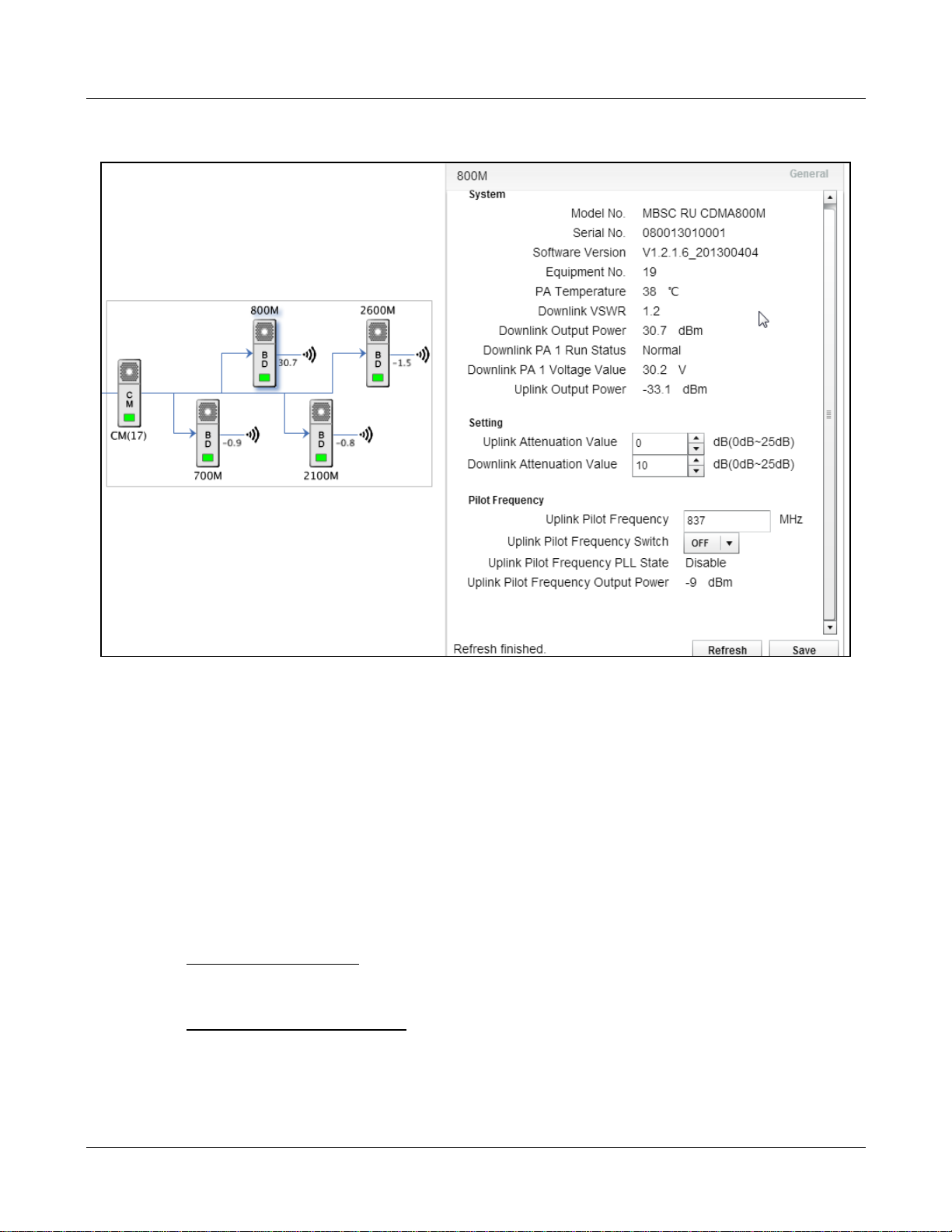
MBSC-C RU
Figure 52 – Up/Down Link Verification
5.4.4.2 Using Uplink Pilot Tone Generator
Each RU in the remote node is equipped with an Uplink P ilot Tone Generator which will generate a CW RF
tone out of the RU back towards the FIU and BIU.. By measuring the RF power at the RXout port of the BIU
the end-to-end uplink system gain can be verified , and band-to-band / node-to-node, variations calibrated
without additional test equipment required at the Remote Node.
Verify the end-to-end Uplink Gain for each frequency band as follows:
1. Click on the RU for the desired frequency band. The component windo w ;will pop up as shown in
Figure 52 – Up/Down Link Verification
a. Uplink Pilot Frequency: Set the frequency to the center of the spectrum to be used in the
system (if the operator licensed bands are not known set the frequency to center of the band
– e.g. 1732.5 MHz for AWS band)
b. Uplink Pilot Frequency Switch: select ON from the drop-down box
c. Click Save to turn the Uplink Pilot generator ON
2. Connect an RF power meter to the corresponding RXout port of the BIU
a. A -6 dBm value in the Uplink Pilot Frequency Output Power f ield of the RU corresponds to an
equivalent signal of -60 dBm at the input to the RU
MBSC-C RU December 15, 2015
Page 63
Page 73
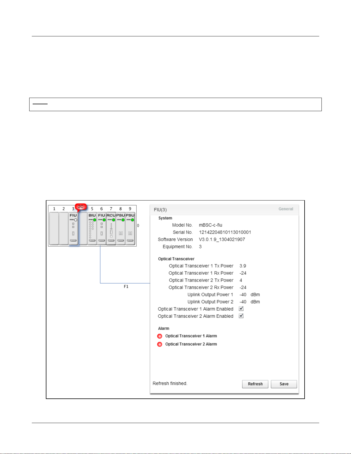
MBSC-C RU
b. Variat ions in fil tering, ampl ifiers , and optical loss may cause the ac tual system gain t o vary +/ -
6 dB. All paths can be normalized by adjusting uplink attenuation settings in the BIU.
3. This procedure should be repeated for each frequency band in the s ystem
Note: Uplink Pilot Frequenc y Switch should be off during normal operations. This function is intend ed for testing, verifying,
and adjusting uplink performance an d will interfere with normal operat i on of the system.
5.5 Monitoring and Alarms
5.5.1 Operational Status
5.5.1.1 Host Unit
The EMS Local GUI graphical interface will notify users of an error or malfunction in the Host Unit with a red
popup “alarm indicator”. The alarms will also be displayed in the lower section of the component window.
Figure 53 - Host Unit Alarm Status
MBSC-C RU December 15, 2015
Page 64
Page 74
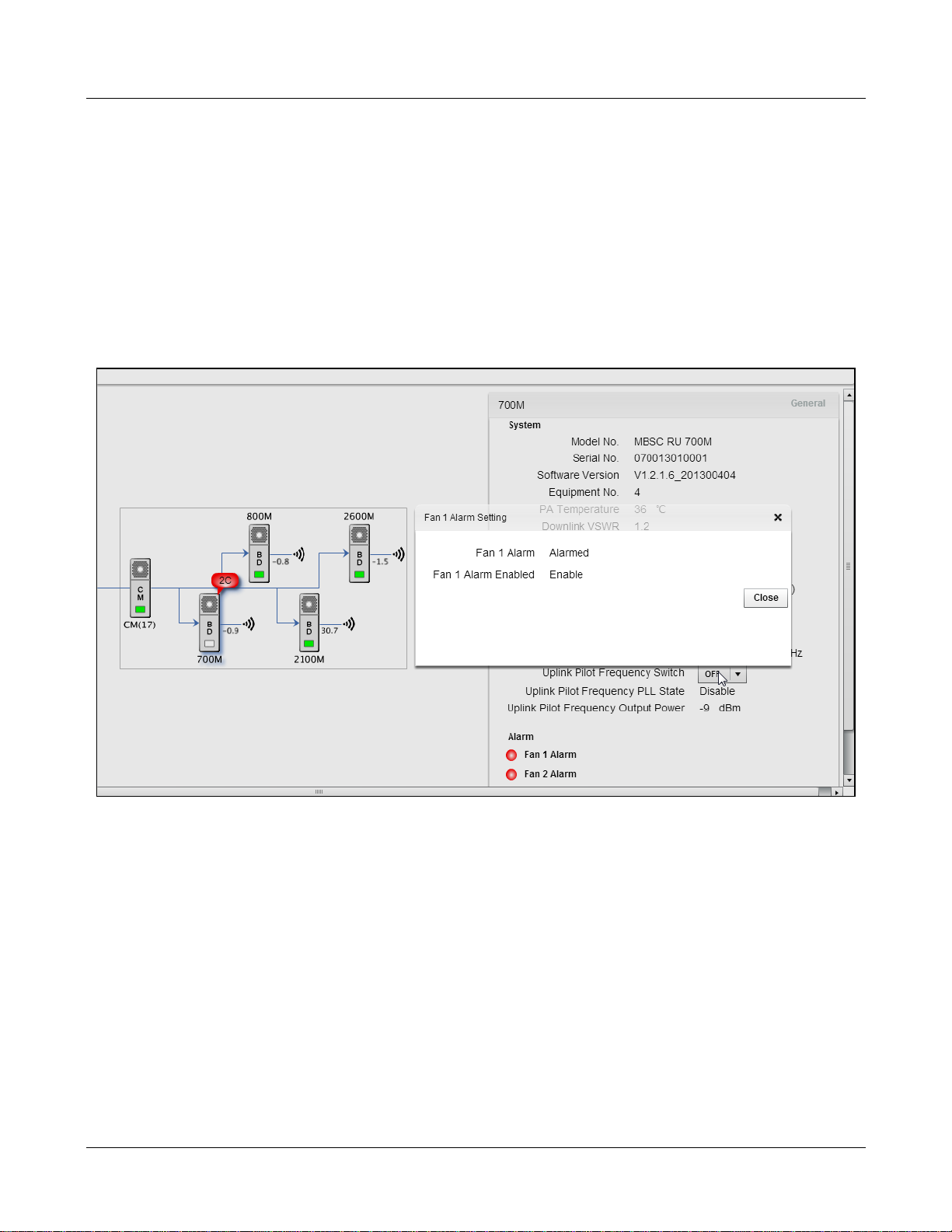
MBSC-C RU
5.5.1.2 Remote Node
In the case of a Remote Node malfunction, the affected unit will also be marked with a red popup “alar m
indicator”. Figure 54 - Remote Node Alarm Status illustrates a condition where both fans of an RU are not
working (power cable disconnected):
1. The alarm indicator beside the affected RU in the topology view displays “2C”
2. Additional alarm status is shown in the lower right section of the RU component wi ndow.
Figure 54 - Remote Node Alarm Status
MBSC-C RU December 15, 2015
Page 65
Page 75

MBSC-C RU
Alarm
ID
Optical RX signal is detected by the FIU
Remote Node (CM)
A system over-temperature alarm has
been reported
Optical RX signal is detected by the FIU
Remote Node (CM)
Low/No optical signal is detected on Link
1
Low/No optical signal is detected on Link
2
Optical RX signal is detected by the CM
Host Unit (FIU)
A system over-temperature alarm has
been reported
Power has been lost at the Remote Node
delivery)
5.5.2 System Alarms
The MBSC1900-040-RU provides alar m indications for equipm ent malfunctions or for conditions that place
the out of standard operating range (such as over-power). A complete list of alarm events, and the
originating product module, is provided in Table 15 System Alarms.
These events are enabled by default factory settings, but can be disabled if desired.
These alarm events can be observed in multiples ways:
- In the EMS Local GUI in the network topology view and corresponding component parameter
windows
- In the Moni tor window of the remote EMS Server
- As SNMP traps issued by the remote EMS Server (if enabled)
Table 15System Alarms
Item Equipment Module
1
Host Unit RCU
2 423000 System Temperature
3
Host Unit FIU
4 422000 Optical Transceiver 1
5 422100 Optical Transceiver 2
6
7 423000 System Temperature
Remote
Node
CM
401500 Host/Remote Link
401500 Host/Remote Link
401500 Host/Remote Link
Alarm Name Description
but no logical connection exists to the
but no logical connection exists to the
but no logical connection exists to the
8 400100 Power Down
9
10 427000 PA Over Output Power PA output power exceed threshold
11 401620 PA Over Driver PA overdrive condition exists
12 400600 PA Over Temperature High temperature condition in final PA
MBSC-C RU December 15, 2015
Remote
Node
RU
(internal battery backup enables alarm
401920 PA Over VSWR High VSWR detected at output of PA
PA
Page 66
Page 76
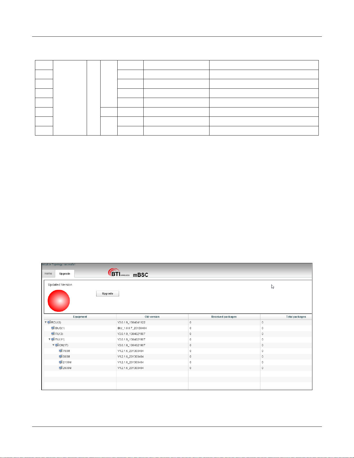
Alarm
stage
MBSC-C RU
13 427100 PA Lower Gain Alarm Low gain condition (< 10dB) detected
14 415510 PA Loop Alarm Error correction loop unlocked
15 400310 PA Voltage Alarm PA voltage outside range
16 401300 PA Fault Alarm Internal PA fault detected
17 SSM 401000 Uplink LNA Fault Alarm Internal LNA fault detected
18
19 408302 Fan 2 Alarm Fan 2 is non-functioning (low current)
408301 Fan 1 Alarm Fan 1 is non-functioning (low current)
FAN
5.6 System Upgrade
To conduct a system upgrade, navigate to the upper right section and cl ick on “Upgrade”.
5.6.1 Verify Software Versions
Verify component versions in the second column of the Upgrade tab.
5.6.2 Upgrade component software
Click on the “Upgrade” button and locate the firmware file to start the component upgrade. Note: Eac h
component upgrade time differs from one another ranging fro m 5 mi nutes to 120 minutes.
Figure 55 - Component Upgrade
MBSC-C RU December 15, 2015
Page 67
Page 77

MBSC-C RU
6 Maintenance
Note: Check your sales order and equ ipment warranty bef ore attempting to ser vice or repair the mBSC -C system. Breaking
the seals on equipment under warranty will void the warranty. Do not return equipment for warranty or repair until proper
shipping instructions are recei v ed from the factory.
6.1 Electrostatic Discharge Precautions
The mBSC-C system modules contain assemblies and components which are sensitive to electrostatic
discharge (ESD). Carefully observe the precautions and recommended procedures to verify that system
reliability is not compromised due to component damage from static electricity.
The following precautions will significantly reduce the risk of system failure or malfunction due t o E SD:
1. Always wear a grounded wrist strap while work i ng around the system
2. Consider all assemblies, components and connections to be ESD sensitive
3. When unpacking circuit boards, interfaces and modules that are packaged separately from the
system, keep them in their conductive wrapping until they are ready to be installed.
4. Before removing or replacing any co mponents, select a work area where potential static sources
are minimized
5. Handle circuit packs and boards by the grounded housings, avoiding contact with the connectors
6.2 Preventative Maintenance
The mBSC-C system requires minimal regular maintenance to ensure continuous and satisfactory operation.
Maintenance includes diagnosing and correcting the service problems as they occur. When an alarm is
reported, it is necessary to follow a troubleshoot i ng procedure to identify the source of the problem.
The following are recommended routine maintenance procedures:
Check the indicator status LEDs (normal or alarm ).
Prevent dust or grime from accumulating on the s urface of heat sinks.
Check power output.
6.3 Fault Detection and Alarm Reporting
The mBSC-C on-board embedded firmware detects unit and system faults and reports them as system
alarms. The following methods may be used to report alarms:
Dry-contact alarm points
Status LEDs on system components
NMS (Local GUI, remote NMS, and SNMP Alarms)
MBSC-C RU December 15, 2015
Page 68
Page 78

MBSC-C RU
2) Downlink path BTS input signal is low/not present
Measure the downlink output power at the output of the RU, and at the input to he antenna
4) RU is faulty.
1) Test calling in the coverage area of original BTS. It may be the BT S problem if the
1) Measure the DC power input source. If the voltage is out of 48VDC +/- 20%, add a
2) The interior power unit is faulty.
The mBSC-C Host Unit components are equipped with multiple LED indicators that show status and alarms
by displaying Green, Red or Off. Detailed descriptions of the LED indicators are provided res pectively in
section 3.2.7Host Unit Interface.
The NMS software provides detailed alarm inf ormation whi ch inc ludes modul e level faul ts, circuit faults and
measured value faults such as door, RF power and temperature.
6.4 Troubleshooting Quick Guide
Use this section to quickly troubleshoot alarms and faults.
Table 16 Troubleshooting Quick Guide
Problem Quick Troubleshooting Steps / Possible Cause
1) Optical path is faulty;
No RF output
3) Remote Node RU is faulty.
RF output power level is low
Loss of phone service, but the
RF signal level is normal
Power supply is out of service
1)Passive components between the RU a nd the antenna port are faulty;
2) Host Unit RF input connections are faulty;
3) Optical path is faulty;
situation is the same;
2) Measure the gain both of the forward path and reser ve path to see whether they are
close;
3) RU LNA module is faulty.
regulated power supply between the power in connector and the power source.
MBSC-C RU December 15, 2015
Page 69
Page 79
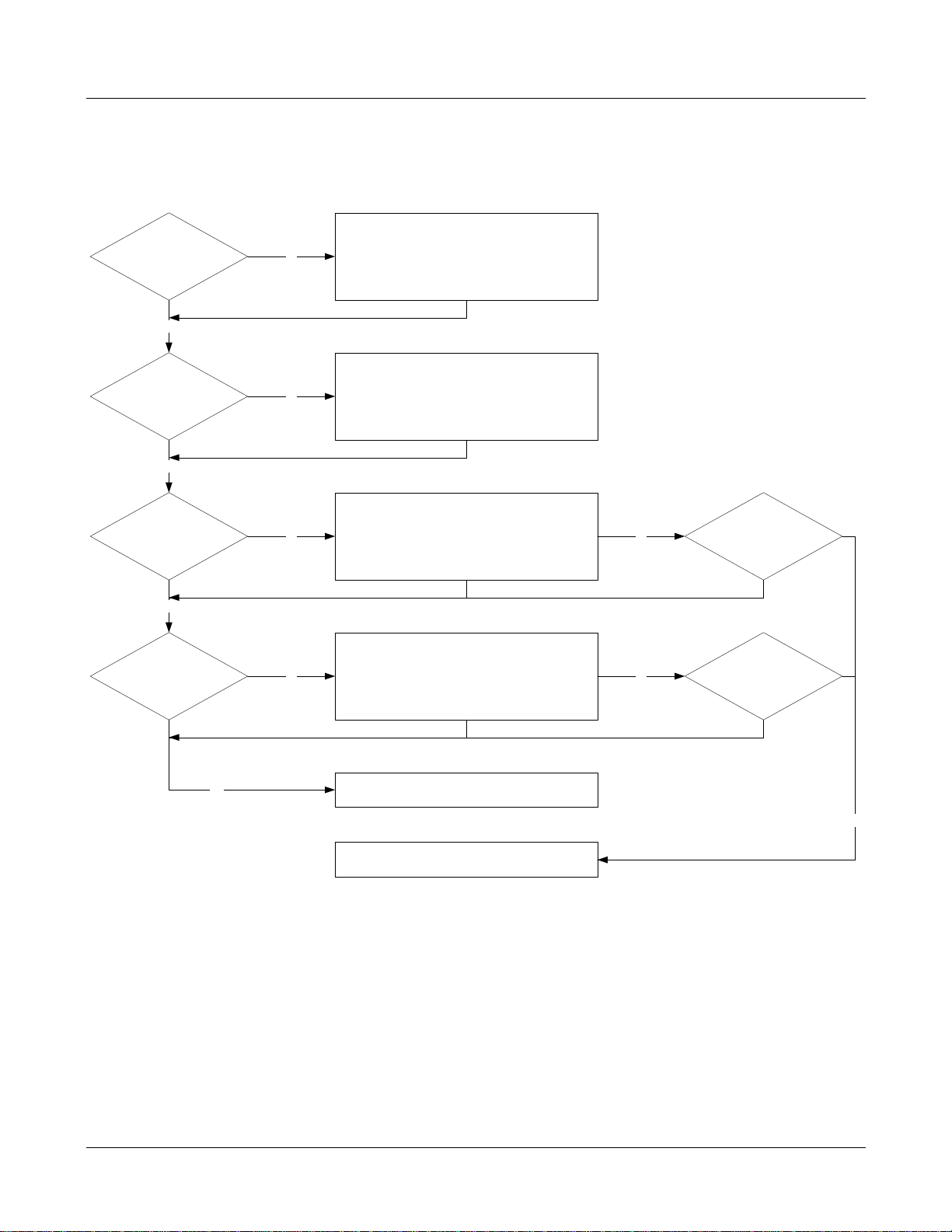
Is the HU shelf
grounded?
Is the PSU
LED
Green?
Check the grounding connection and connect
the ground cable to the HU
No
Yes
Check the power cable connection.
Check the power supply connection
.
Check the PSU switch.
No
Is the BIU LED
Green?
Yes
Check for pin connector damage on the BIU. If
undamaged, reseat the board. Uninstall the BIU
and re-
insert the BIU into the HU slot.
No No
Spare BIU available?
Is the FIU LED
Green?
Yes
Check for pin connector damage on the FIU. If
undamaged, reseat the board. Uninstall the FIU
and re-insert the FIU into the HU slot.
LED in Red: both fiber connections are open
LED in Yellow: one fiber connection is open
No No
Spare FIU available?
Installation complete and continue to NMS
installation
Yes
Contact local BTI customer serv
ice
No
6.4.1 Host Unit Trouble Shooting
MBSC-C RU
Figure 56Host Unit Trouble Shooting
MBSC-C RU December 15, 2015
Page 70
Page 80
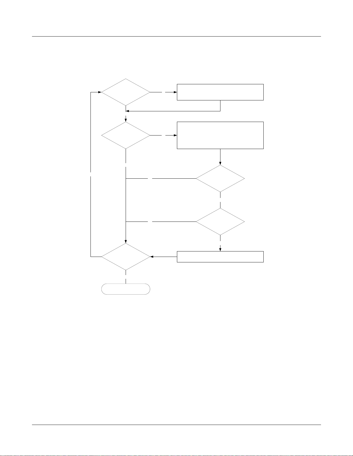
6.4.2 Remote Unit Trouble Shooting
LED on?
LED status
• Check power switch
• Check mains cabling
• Check mains power
No
Yes
• Check the fiber cable connection on the fiber
CM-BTS enclosure
• Check that the HU is installed and power is on.
• Check the fiber cable connection on the HU.
red
Are all RU units
installed?
LED status green?
Spare FIU available?
Contact local BTI customer servcie
No
No
Installation status:
Complete or terminated
Yes
Yes
green
Yes
No
MBSC-C RU
Figure 57Remote Unit Trouble Shooting
MBSC-C RU December 15, 2015
Page 71
Page 81

MBSC-C RU
Terms/Acronyms/Abbreviation
Definition
German standards RF connector:
7mm OD of inner contact, 16mm ID of outer contact.
7 Terms, Acronyms & Abbreviations
Table 17 T erms, Acronyms and Abbreviations
ANT Antenna
AWG American Wire Gauge
BTS Base Transceiver Station or Base Transceiver System
C° Degree Celsius
COM Serial Communication Port
CQT Call Quality Test
dB Decibels
dBm Po wer measurement referenced to the specific power level of one milli watt
DCS Digital Cellular System
DIN Deutsches Insitut für Normung eV (German standardsinstitution)
7-16 DIN
DL Downlink
DT Driver Test
EMC Electromagnetic Compatibility
GSM Global System for Mobile Communicati ons
LED Light Emitting Diode
LNA Low Noise Amplifier
NMS Network & Monitoring System
MCPA Multi-carrier Power Amplifier
MHz Megahertz
MTBF Mean Time Between Failures
OMC Operation Monitor Center
PA Power Amplifier
RF Radio Frequency
RX Receive or Receiver
SMA Subminiature Type A coaxial connector
TX Transmit, Transmitter
UMTS Universal Mobile Telecommunications System
VSWR Voltage Standing Wave Ratio
MBSC-C RU December 15, 2015
Page 72
Page 82

MBSC-C RU
Technical Parameter:
728
698
Downlink:
46.25dBm(For 40W); 43.35Bm(For 20W);
Uplink: 15.3
15.35dBm(For 40W); 15.28dBm(For 20W);
LTE(W
Frequency Range Downlink
Uplink
Operating Bandwidth 18MHz/11MHz
Multiple Carrier Supported 1
Channel Spacing(s)
/ Bandwidth(s)
Maximun RF Output Power
Max Gain Downlink: 62.41dB/62.27dB, Uplink: 62.43dB/62.24dB.
Type of modulation and
Designator
Antenna Type External antenna (N female)
Antenna Gain Downlink: 17dBi
LTE:1.4MHz, 3MHz, 5MHz, 10MHz
46.31dBm(For 40W); 43.37dBm(For 20W);/
7D)
MHz~746MHz/746MHz~757MHz
MHz~716MHz/776MHz~787MHz
4dBm(For 40W); 15.38dBm(For 20W)./
Uplink: 17dBi
8 Packing List
List brand quantity
mBSC1900-040-RUC11 BTI Wireless 1
Power cable / 1
T
o submit your comments by mail, use the response card behind the front cover of your document, or
write to the following address:
Attn: Publications Manager
BTI Wireless
6185 Phyllis Drive
MBSC-C RU December 15, 2015
Page 73
Page 83

Cypress, CA 90630
We appreciate your comments.
MBSC-C RU
For US and Canadian installations: FCC RF exposure compliance requires
ollowing antenna installation
the f
and device operation configurations be satisfied:
A separation distance of at least 9 meters must be maintained between the antenna of this device and all
persons. RF exposure compliance may need to be addressed at t he time of licensing, as required by the
responsible FCC Bureau(s), including antenna c o-location requirements of 1.1307(b)(3). §2.1091
Maximum permissible antenna gain is 17 dBi.
IC STATEMENT Operation is subject to the following two conditions:
(1) This device may not cause interference, and
(2) This device must accept any interference, i ncluding interference that may cause undesired operation of
the device.
Le présent appareil est conforme aux CNR d'Indu strie Canada applicabl es aux appareils radio exempts de
licence.
L'exploitation est autorisée aux deux conditions suivantes :
(1) l'appareil ne doit pas produire de brouillage, et
(2) l'utilisateur de l'appareil doit accepter t out brouillage radioélectrique subi, même si le brouill age est
susceptible d'en compromettre le fonctionnement.
IC Radiation Exposure Statement
This equipment complies with IC radiation exposure li mits set forth for an uncontrolled environment. This
equipment should be installed and operated with minimum distances 6 m between the radiator include
antenna & your body.
IC Déclaration sur la radio exposition
Cet équipement est conforme avec l'exposition aux radiations IC définies pour un environnement non c ontrôlé .
Cet équipement doit être installé et utilisé avec une distance minimale de 9 m de entre le radiateur inclure
l'antenne et votre corps.
MBSC-C RU December 15, 2015
Page 74
 Loading...