

Page 1
353000
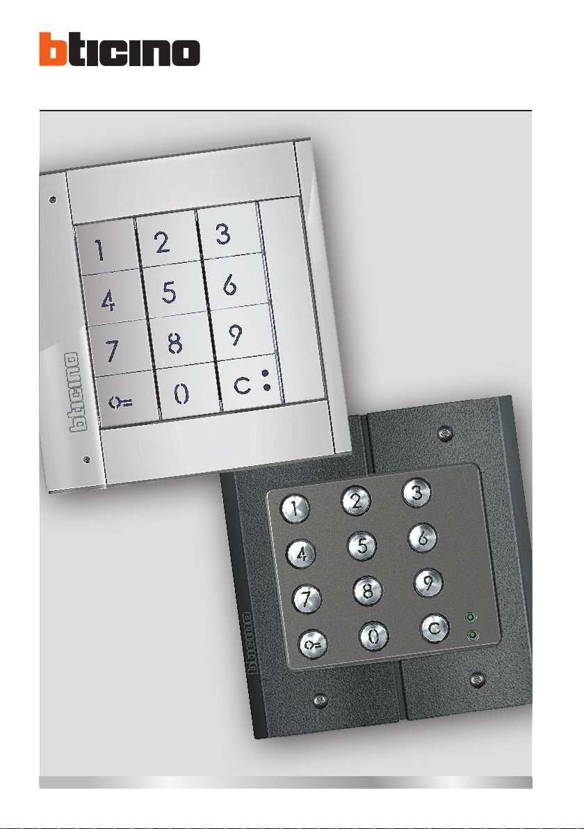
Sfera Keypad Module
Installer manual
04/16-01 PC
Page 2
2
Page 3
Sfera Keypad Module
Contents
1 Introduction 4
1.1 Warnings and recommendations 4
2 Description 5
2.1 Main functions 5
2.2 Front view 6
2.3 Back view 7
3 Configuration 8
3.1 Master code 8
3.1.1 New master code 8
3.1.2 Deleting master codes 10
3.2 Passepartout code 11
3.2.1 New passepartout code 11
3.2.2 Deleting passepartout codes 13
3.2.3 Replacing the passepartout code 14
3.3 Resident code 16
3.3.1 New resident code 16
3.3.2 Deleting the resident code 19
3.3.3 Replacing the resident code 20
Installer manual
4 Advanced configuration 22
4.1 Connection to the PC 22
4.2 Door lock control 23
4.2.1 Door lock control with stand-alone Keypad module 353000 23
4.2.2 Door lock control with Sfera Speaker Module 351100/351200/351300
and Keypad module 353000 23
4.3 Reset 24
5 Appendix 25
5.1 Technical data 25
3
Page 4
1 Introduction
1.1 Warnings and recommendations
Before proceeding with the installation we recommend that you read the content of this manual
very carefully.
The warranty will automatically become void in case of negligence, improper use, and tampering
by unauthorised personnel.
The Sfera Keypad Module must only be used with BTicino 2 wire digital systems.
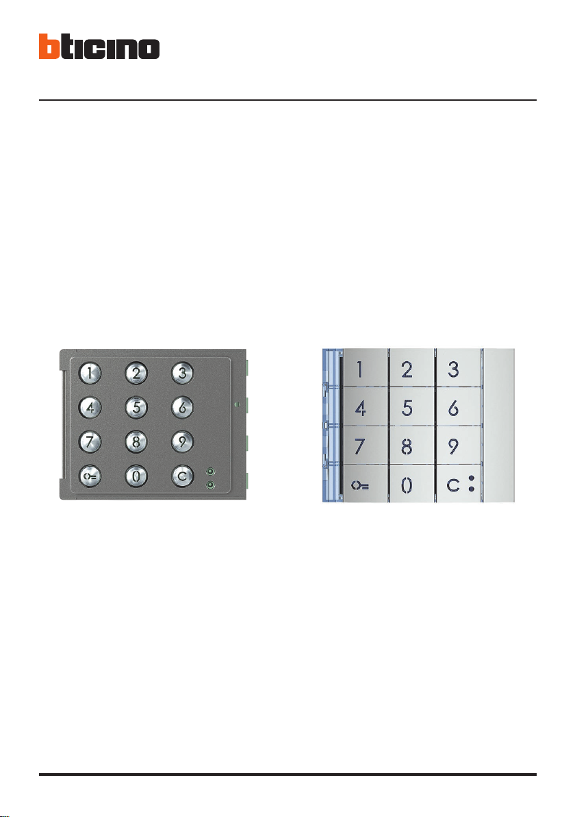
Front covers that may be used with the Sfera BTicino Keypad Module:
Front cover 353005 Front cover 353001/02/03
4
Page 5

2 Description
Sfera Keypad Module
2.1 Main functions
The BTicino Sfera Keypad Module can be used by residents to open a door lock using previously
stored numerical codes.
The device consists of a backlit pushbutton panel with 12 keys and luminous indicators, for controlling that the code has been entered correctly.
This manual refers to the Sfera wired stand-alone Keypad Module or paired with the
Sfera Speaker Module (351100/351200/351300).
If the Sfera Keypad Module is installed linked to the Display Module (352500) refer to
the Display manual for the code programming.
Programming can be performed in two ways:
- using the TiSferaDesign software supplied with the product (chapter 4);
- following specific procedures, performed directly on the keypad (chapter 3).
In order to configure the master codes remove the front cover and press the programming pushbutton indicated in the legend (chapter 2.2).
The secret code must consist of minimum 4 and maximum 9 digits.
Three different types of codes may be programmed:
- MASTER Code providing access to the programming of other codes.
It can only be used for programming, not for access..
- PASSEPARTOUT It can be used to open the door lock the entrance panel is associated to.
It’s not linked with any apartments.
It can only be used for access, not for programming.
- RESIDENT It can be used to open the door lock the entrance panel is associated to.
It’s linked to an apartment of the system.
It can only be used for access, not for programming.
Installer manual
5
Page 6
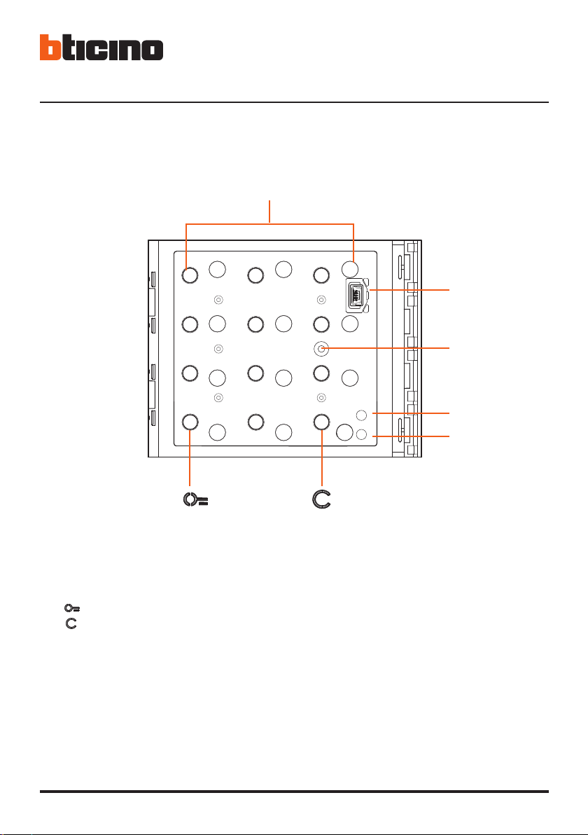
2.2 Front view
2 Description
1
2
3
4
5
1 - Digital keypad + key illumination LED.
key for the selection of the door lock release code.
key for the replacement of the codes.
2 - Mini-USB programming connector.
3 - Programming pushbutton.
4 - Red LED on steady: access denied, or programming error.
5 - Green LED on steady: access granted, or programming successful.
6
Page 7
Sfera Keypad Module
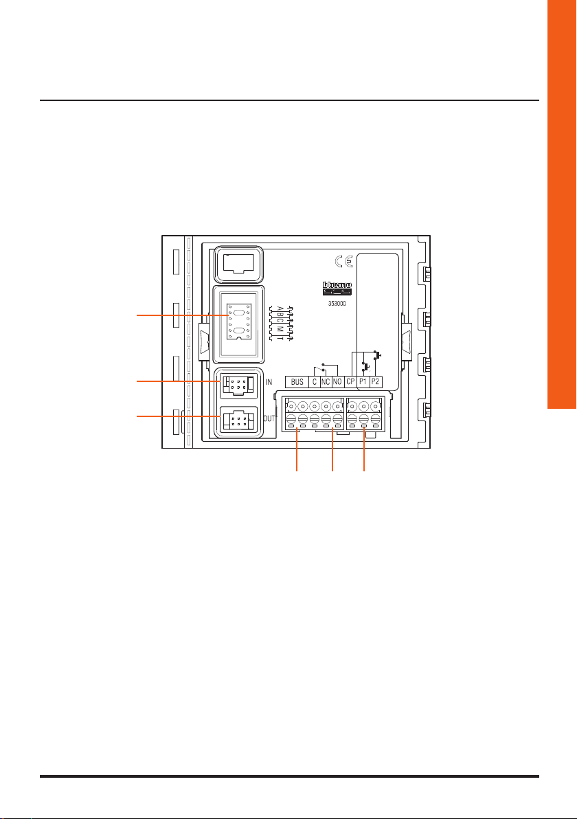
2.3 Back view
Installer manual
6
5
4
3 2 1
1 - Connection of door lock pushbutton (CP-P1) and tamper (CP-P2 – future application).
2 - Local relay contacts.
3 - Connection to the BUS.
4 - Connector for the connection to subsequent modules.
5 - Connector for the connection to previous modules.
6 - Configurator sockets.
7
Page 8
3 Configuration
3.1 Master code
(only with Sfera Speaker Module 351100/351200/351300 and the associated Sfera Pushbutton
Modules 352000/352100 or only with the Sfera Keypad Module)
For safety reasons, the system gives the installer the possibility of programming a “MASTER” code.
This can be used to access the programming of the other codes (passepartout and resident codes).
To access programming mode, a master code must be assigned to the device.; up to 20 master
codes may be saved.
The keypad module will indicate that the code has been accepted or deleted by means of audible
signals and the switching on of the green LED. If an unrecognised code is entered, programming
will stop. This interruption is confirmed by a long beep, and the red LED coming on.
3.1.1 New master code
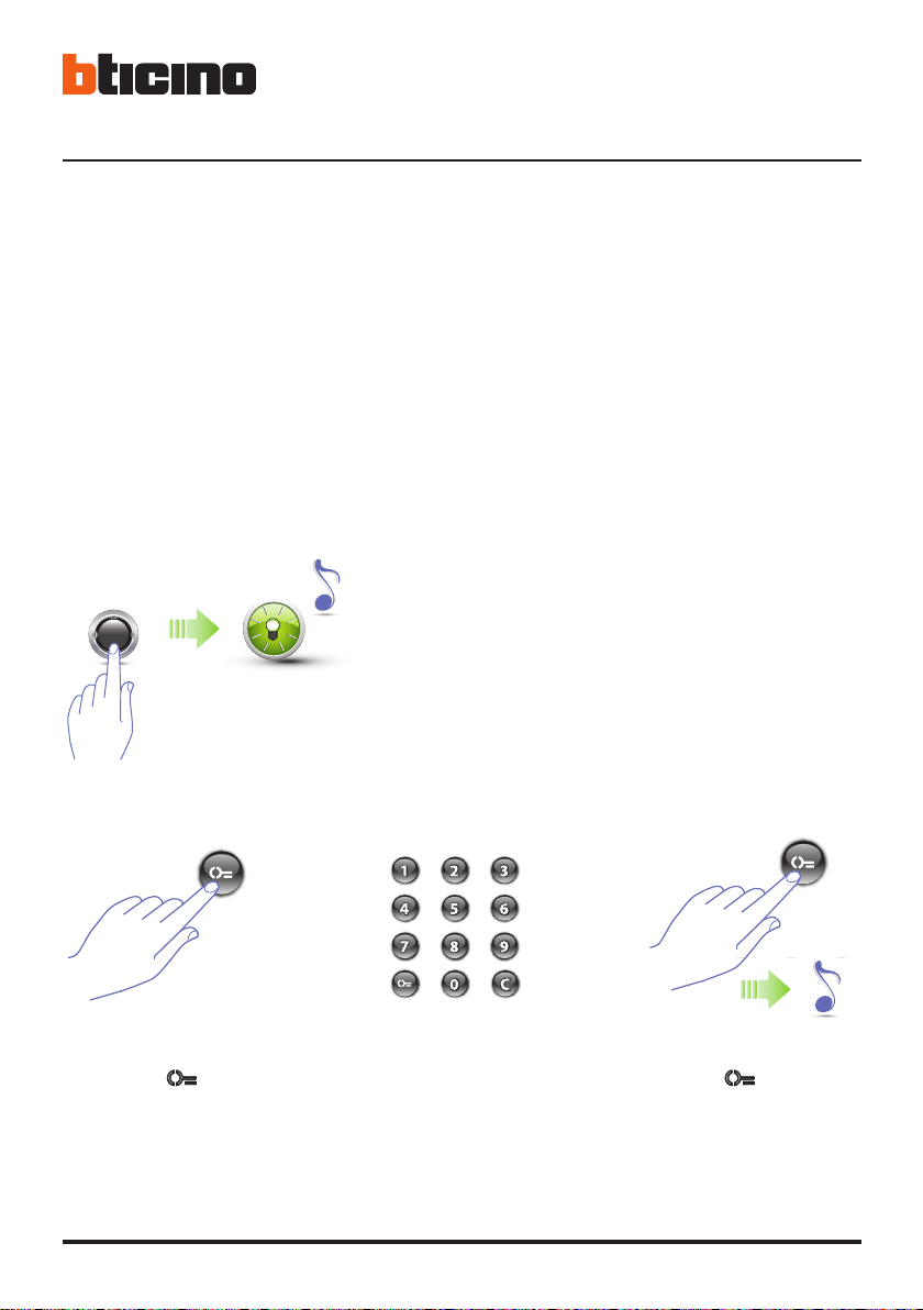
1 Press the programming pushbutton until the green
LED flashes and a confirmation beep is heard.
2 Press the key. 4 Press the key.
8
3 Enter the code (4
to 9 digits).
A short beep confirms the
programming of the new
master code
Page 9
Sfera Keypad Module
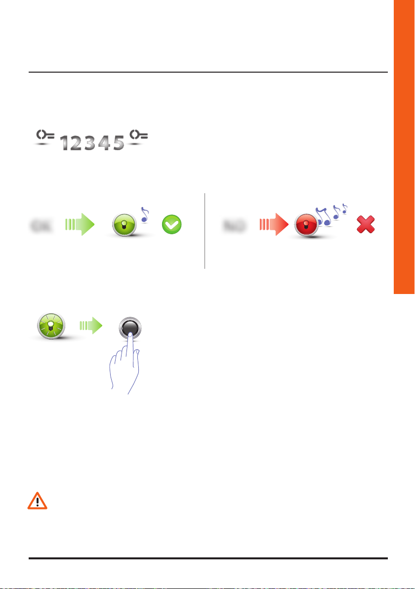
5 Re-enter the code to confirm.
Installer manual
OK
Correct code:
green LED on and short beep.
A short beep and the LEDs switching off indicate that the programming procedure has been
terminated. The Sfera Keypad Module is now ready for normal operation.
During programming, some rules must be followed:
- keys must be pressed consecutively (maximum 2 seconds between pressures);
- the programming sequence must be started within 30 seconds from the moment the
programming pushbutton has been pressed and must be completed in one stage.
NO
Wrong code:
red LED on and long beep
If the procedure has been successful, the
green LED stays on for approximately 1 second
before starting to flash again.
Enter another code, or finish.
6 Press the programming pushbutton, or wait 30
seconds to exit the procedure.
9
Page 10
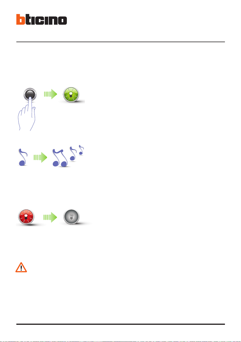
3.1.2 Deleting master codes
3 Configuration
1 Press and hold down the programming pushbutton;
the green LED flashes.
2 Continue holding down the pushbutton;
the device emits 1 beep per second, and a long beep
after ten seconds
3 The red LED flashes and then switches off to confirm
that the deletion has been performed.
- The procedure will delete all the stored Master codes.
- During the procedure press the programming pushbutton.
- To stop the deletion procedure release the programming pushbutton.
- To only delete a specific code use the TiSferaDesign software.
10
Page 11
Sfera Keypad Module
3.2 Passepartout code
(only with Sfera Speaker Module 351100/351200/351300 and the associated Sfera Pushbutton
Modules 352000/352100 or only with the Sfera Keypad Module)
To access the programming of a “Passepartout” code, a master code is necessary. up to 20
passepartout codes may be saved.
The keypad module will indicate that the code has been accepted or deleted by means of audible
signals and the switching on of the green LED. If an unrecognised code is entered, programming
will stop. This interruption is confirmed by a long beep, and the red LED coming on.
3.2.1 New passepartout code
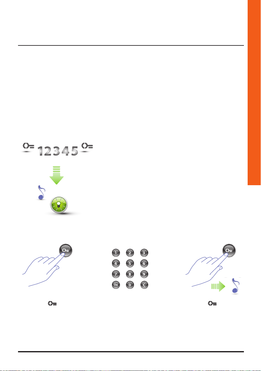
1 Enter the master code.
The device emits a beep, and the green LED
starts flashing.
The programming procedure starts.
Installer manual
2 Press the key.
3 Enter the
passepartout
code (4 to 9 digits).
4 Press the key;
a short beep confirms
the programming of the
new passepartout code.
11
Page 12
3 Configuration
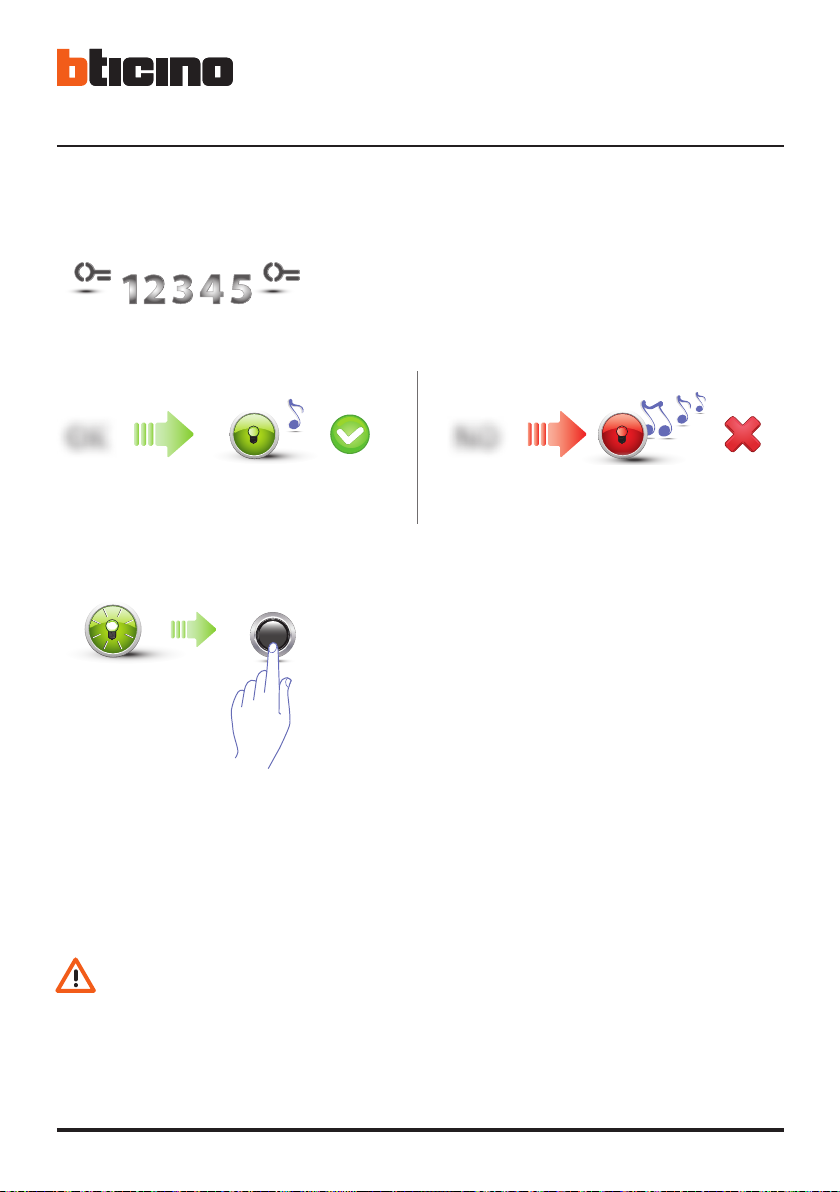
5 Re-enter the code to confirm.
OK
Correct code:
green LED on and short beep.
If the procedure has been successful the green
6 Press the pushbutton, or wait 30 seconds to exit
A short beep and the LEDs switching off indicate that the programming procedure has been terminated. The Sfera Keypad Module is now ready for normal operation.
During programming, some rules must be followed:
- keys must be pressed consecutively (maximum 2 seconds between pressures);
- the programming sequence must be started within 30 seconds from the moment the
programming pushbutton has been pressed and must be completed in one stage.
NO
Wrong code:
Red LED on and long beep.
LED stays on for approximately 1 second, before
starting to flash again. Enter another code, or
finish.
the procedure.
12
Page 13
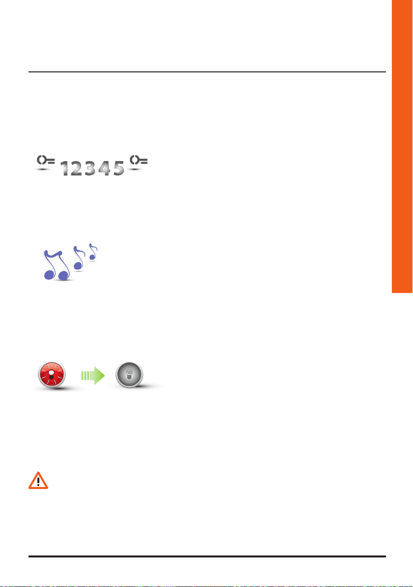
3.2.2 Deleting passepartout codes
Three times
Sfera Keypad Module
Installer manual
1 Enter the master codes three times in succession.
2 The device emits a long confirmation beep.
3 The red LED flashes and then switches off to confirm
that the deletion has been performed.
- The procedure will delete all the stored Passepartout codes.
- To only delete a specific code use the TiSferaDesign software.
13
Page 14
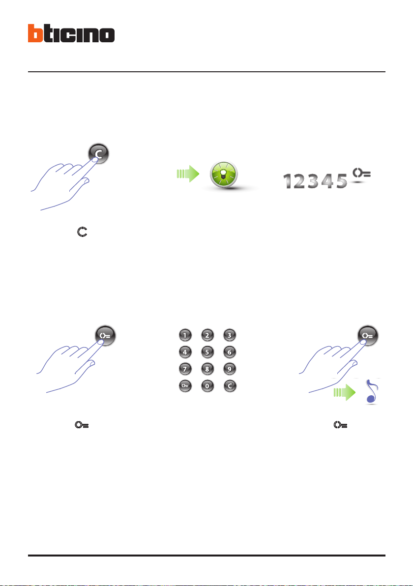
3.2.3 Replacing the passepartout code
3 Configuration
1 Press the key until
the green LED starts
flashing.
4 Press the key.
2 The green LED flashes. 3 Enter the
passepartout code.
5 Enter the new
code.
6 Press the key.
A short beep confirms
the programming of the
new passepartout code.
14
Page 15
Sfera Keypad Module
Installer manual
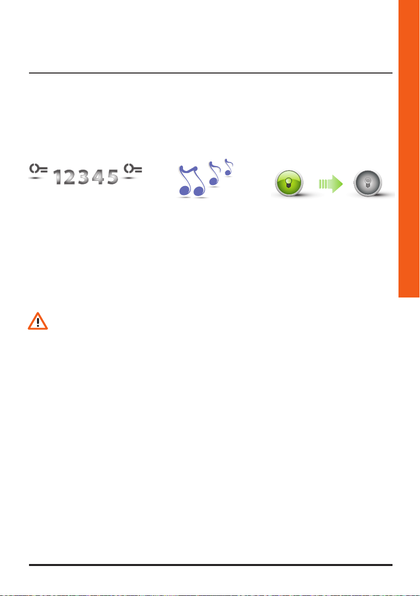
7 Re-enter the code to
confirm.
During programming, some rules must be followed:
- keys must be pressed consecutively (maximum 2 seconds between pressures);
- the programming sequence must be started within 30 seconds from the moment the
programming pushbutton has been pressed and must be completed in one stage.
8 The device emits a
long confirmation
beep.
9 If the procedure has been
successful the green
LED stays on for approximately 1 second before
switching off.
15
Page 16
3 Configuration
3.3 Resident code
(only with Sfera Speaker Module 351100/351200/351300 and the associated Sfera Pushbutton
Modules 352000/352100)
To access the programming of a “RESIDENT” code a master code is necessary. Up to 4000 codes
may be saved, one for each apartment.
The keypad module will indicate that the code has been accepted or deleted by means of audible
signals and the switching on of the green LED. If an unrecognised code is entered, programming
will stop. This interruption is confirmed by a long beep, and the red LED coming on.
This manual refers to the Sfera wired stand-alone Keypad Module or paired with the
Sfera Speaker Module (351100/351200/351300).
If the Sfera Keypad Module is installed linked to the Display Module (352500) refer to
the Display manual for the code programming.
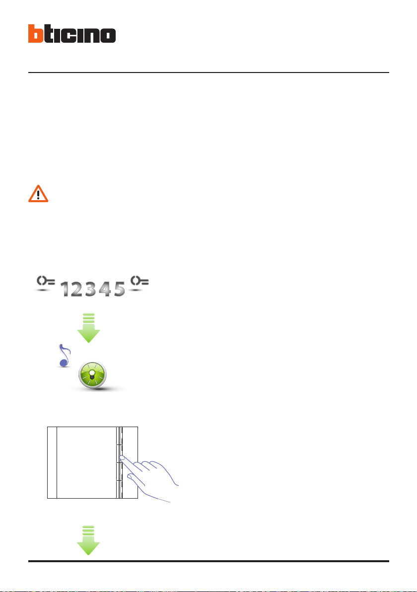
3.3.1 New resident code
1 Enter the master code.
The device emits a beep, and the green LED
starts flashing.
The programming procedure starts.
16
Apartment 1
Apartment 2
Apartment 3
Apartment 4
352041/42/43
2 Use the pushbutton module (352000 and 352100)
to select the apartment the resident code must be
associated to.
Page 17
Sfera Keypad Module
Installer manual
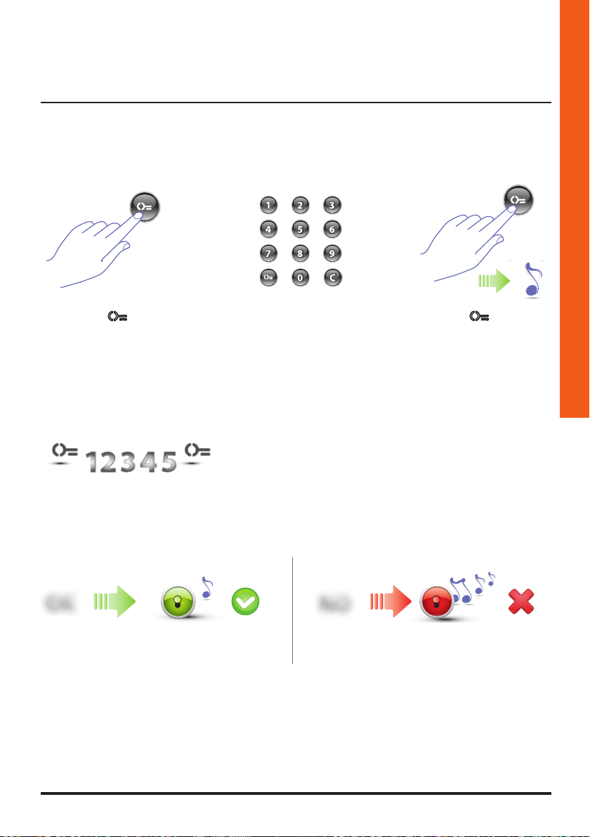
3 Press the key.
OK
Correct code:
green LED on and short beep.
4 Enter the resident
code (4 to 9 digits).
6 Re-enter the code to confirm.
5 Press the key;
a short beep confirms
NO
Wrong code:
red LED on and long beep.
the programming of the
new resident code.
17
Page 18
3 Configuration
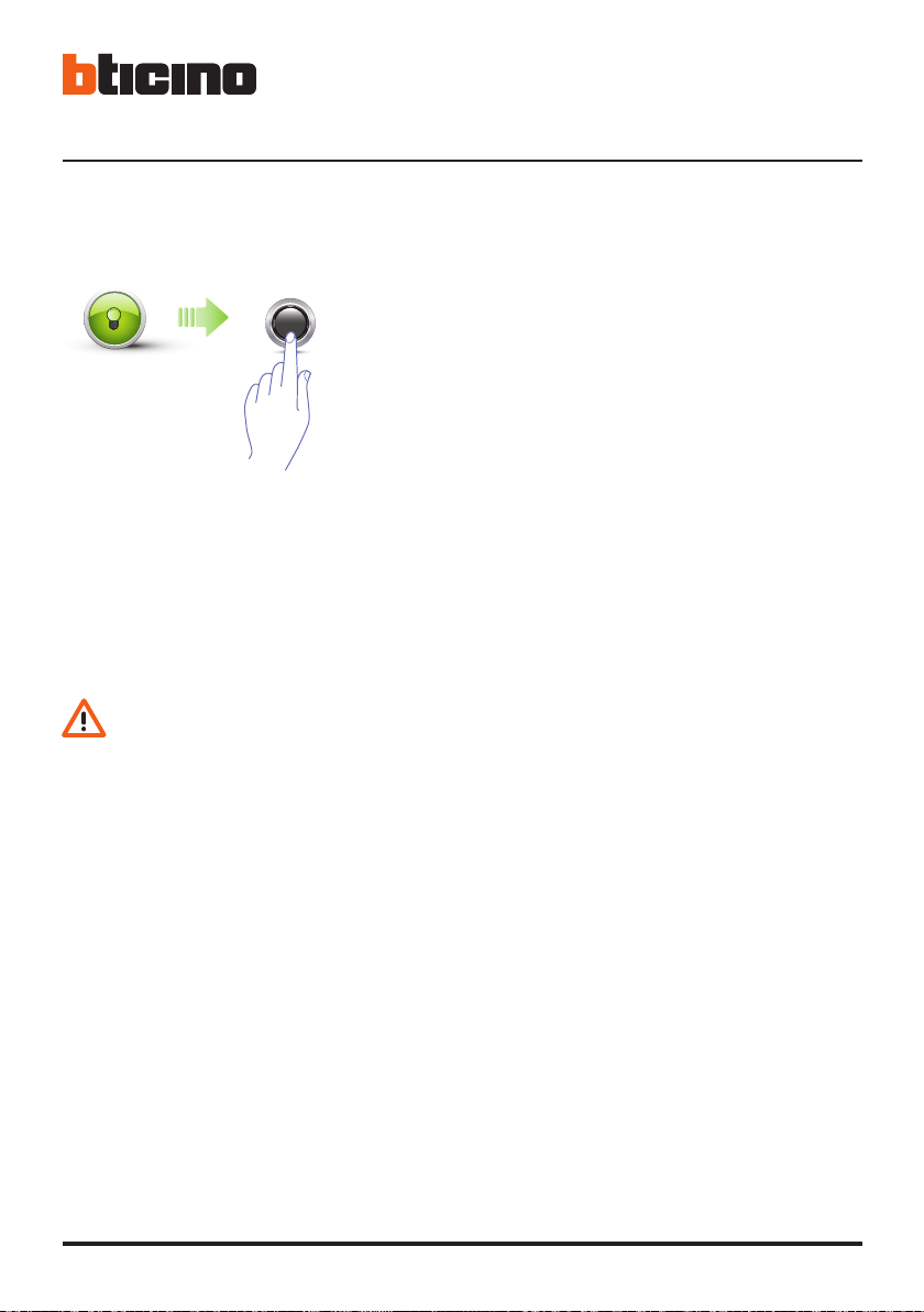
If the procedure has been successful the
green LED stays on for approximately 1
second before switching off.
A short beep and the LEDs switching off indicate that the programming procedure has been terminated. The Sfera Keypad Module is now ready for normal operation.
During programming, some rules must be followed:
- keys must be pressed consecutively (maximum 2 seconds between pressures);
- the programming sequence must be started within 30 seconds from the moment the
programming pushbutton has been pressed and must be completed in one stage.
18
Page 19
Sfera Keypad Module
3.3.2 Deleting the resident code
(only with Sfera Speaker Module 351100/351200/351300 and the associated Sfera Pushbutton
Modules 352000/352100)
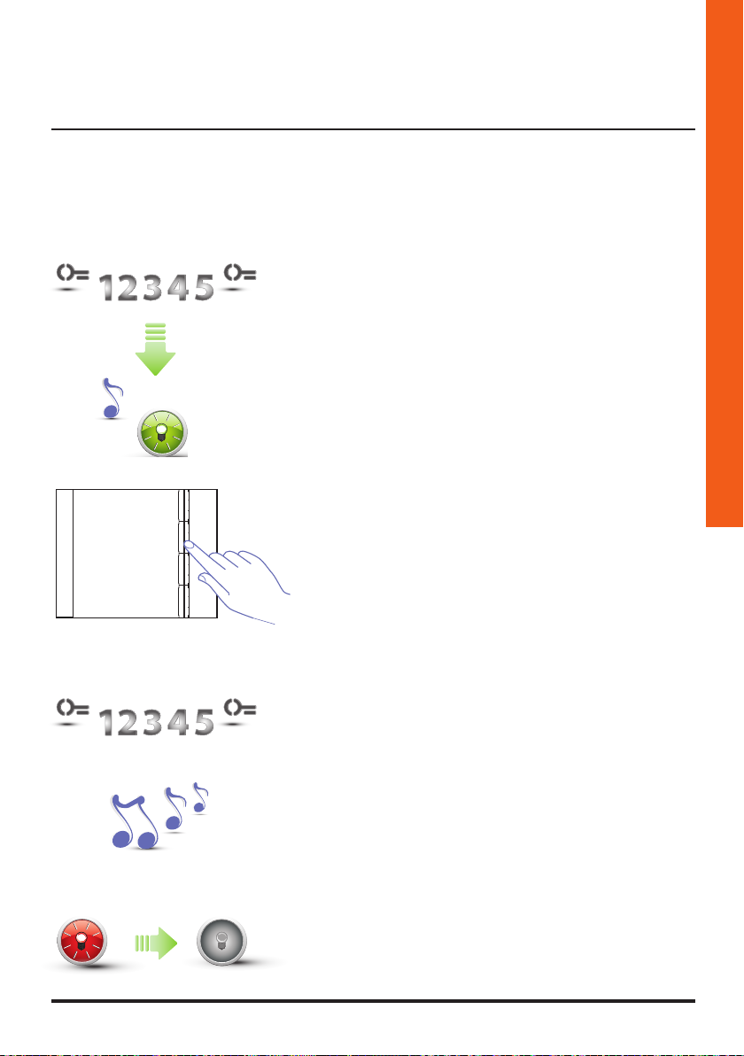
1 Enter the master code.
The device emits a beep, and the green LED
starts flashing.
The programming procedure starts.
Installer manual
Apartment 1
Apartment 2
Apartment 3
Apartment 4
352041/42/43
2 Use the pushbutton module (352000 and 352100)
to select the apartment for which the resident code
must be deleted.
3 Re-enter the master code.
4 The device emits a long confirmation beep.
5 The red LED flashes and then switches off to confirm
that the deletion has been performed.
19
Page 20
3.3.3 Replacing the resident code
3 Configuration
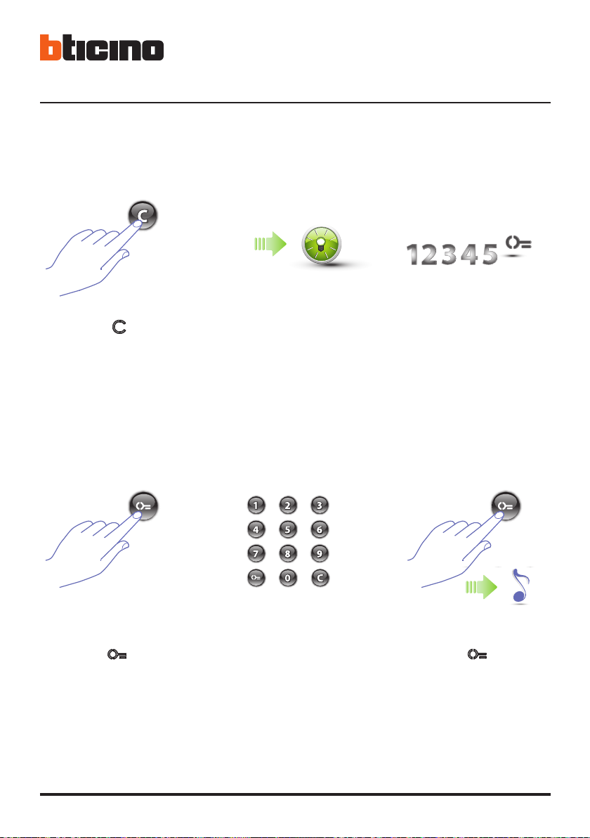
1 Press the key until
the green LED starts
flashing
4 Press the key.
2 The green LED flashes. 3 Enter the resident
code.
5 Enter the new
code.
6 Press the key;
a short beep confirms the
programming of the new
resident code.
20
Page 21
Sfera Keypad Module
Installer manual
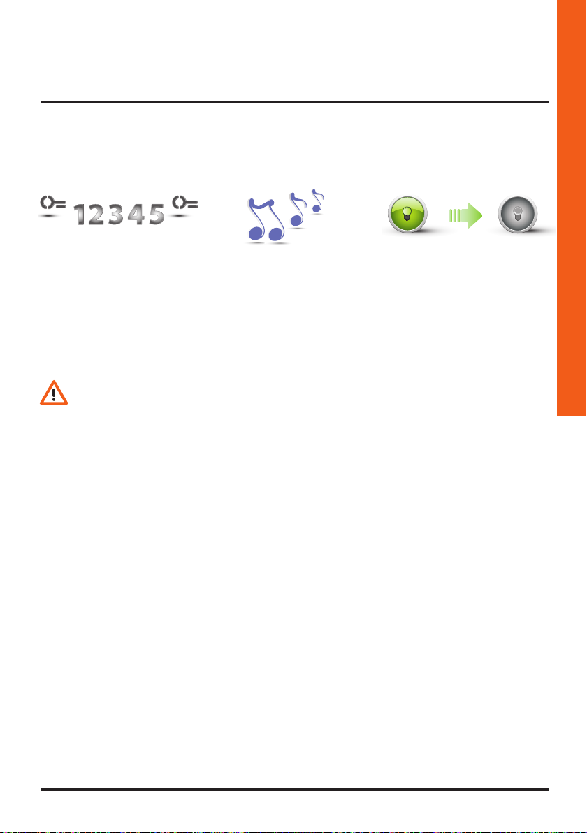
7 Re-enter the code to
confirm.
During programming, some rules must be followed:
- keys must be pressed consecutively (maximum 2 seconds between pressures);
- the programming sequence must be started within 30 seconds from the moment the
programming pushbutton has been pressed and must be completed in one stage.
8 The device emits a
long confirmation
beep.
9 If the procedure has been
successful the green
LED stays on for approximately 1 second before
switching off.
21
Page 22
4 Advanced configuration
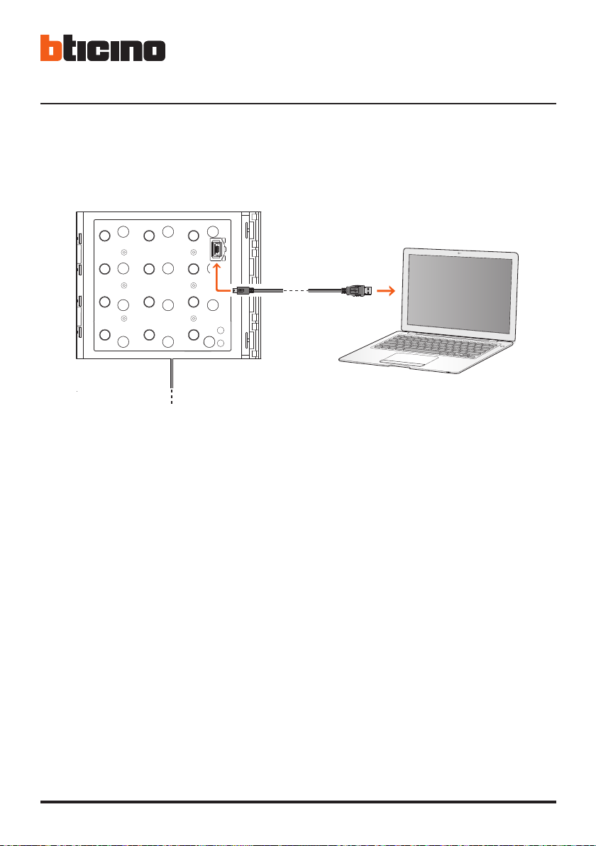
4.1 Connection to the PC
To transfer the configuration performed using the TiSferaDesign software, or to update the
firmware, connect the Sfera Keypad Module to the PC using a USB-miniUSB cable.
mini USB - USB
BUS
When updating the software the device must be powered.
The Sfera Keypad Module connected using a USB cable is recognised by the PC as a virtual port (VIRTUAL COM).
22
Page 23
Sfera Keypad Module
4.2 Door lock control
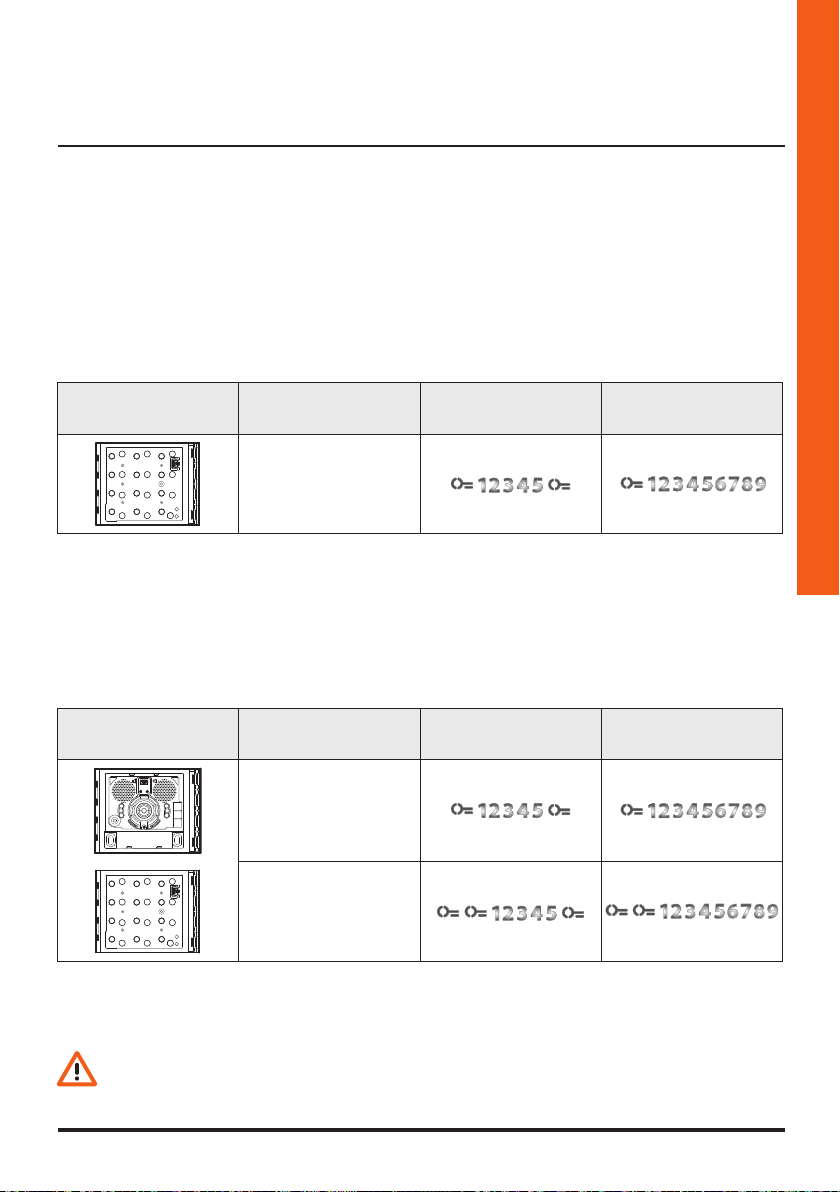
The TiSferaDesign software may be used to set the maximum number of digits to use when composing the code (4 to 9 digits).
Entering the codes to open the door lock varies depending on the code length (if it is shorter
than or the same as the maximum set) and the type of installation.
The correct form to use in the specific cases is shown in the tables below.
4.2.1 Door lock control with stand-alone Keypad module 353000
Stand-alone keypad
module
4.2.2 Door lock control with Sfera Speaker Module 351100/351200/351300 and Keypad module 353000
The link between a Sfera Speaker Module and the Keypad Module allows the management of
two door locks. The table below shows how to use the codes correctly.
Speaker module +
Keypad module
Door lock Short opening code Max. opening code
Door lock connected
to the C/NO/NC local
relay of the keypad
module
Door lock Short opening code Max. opening code
Installer manual
Door lock connected
to the S+ S- contact of
the speaker module
Door lock connected
to the C/NO/NC local
relay of the keypad
module
*
To use this function, make sure that the keypad module is configured with M=3
*
The local relay closing time of the Keypad module is 4” and cannot be modified.
23
Page 24
ON
ON
4 Advanced configuration
4.3 Reset
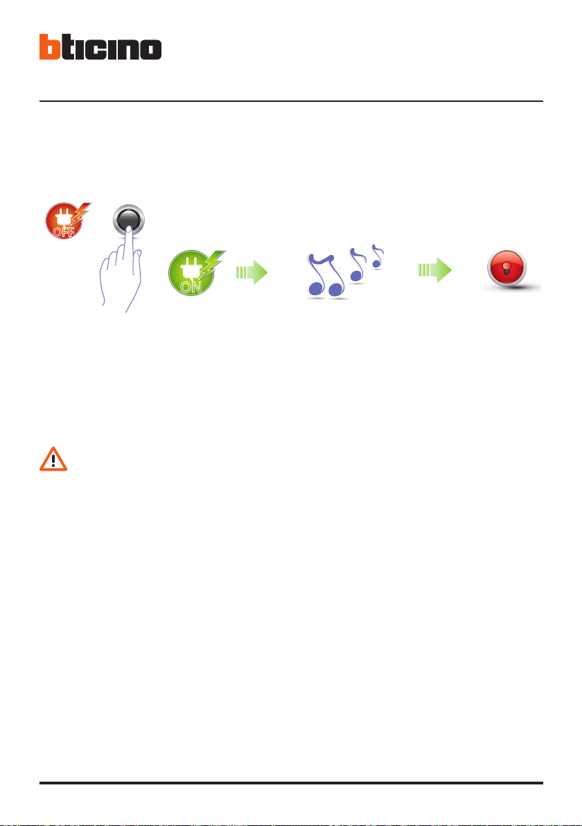
It is also possible to reset the Sfera Keypad Module and delete all the previously set codes; this will
bring the module back to all the default settings.
OFF
OFF
ON
ON
1 Disconnect the power
supply (BUS), press and hold
down the programming
pushbutton and reconnect
the power supply.
In entrance panels with keypad and speaker module, wait one minute after the reset
procedure before starting the programming procedure again.
2 Holding down the
pushbutton until an
extended beep is heard.
3 The red LED
comes on for
4 seconds and
then switches
back off.
24
Page 25
5 Appendix
Sfera Keypad Module
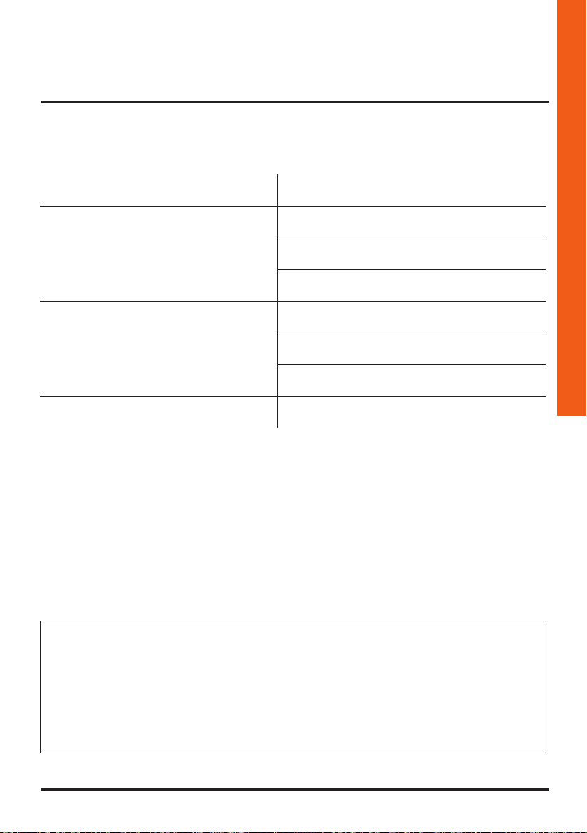
5.1 Technical data
Power supply from BUS 18 – 27 Vdc
10 Ma (Stand-by with LEDs off)
Absorption
Load of local relay contacts
Operating temperature (-25) – (+70) °C
20 Ma (Stand-by with LEDs on)
45Ma (max in operation)
8 A, 30 Vdc
8 A, 30 Vac cosφ = 1
3,5 A, 30 Vac cosφ = 0,4
Installer manual
Technical After-Sales Service
BTicino only accepts responsibility for perfect device operation if it is installed to the
state of the art respecting the indications of the product installation manual.
www.bticino.com
25
Page 26

BTicino SpA
Viale Borri, 231
21100 Varese - Italy
www.bticino.com
BTicino SpA reserves at any time the right to modify the contents of this booklet and to communicate in any form
and modality, the changes brought to the same.
 Loading...