

Page 1
User Manual
Page 2
For assistance, contact:
www.galilmedical.com
USA: Galil Medical Inc., 4364 Round Lake Road, Arden Hills, MN 55112, USA.
Telephone: +1 877 639 2796, Fax +1 877 510 7757
Galil Medical Inc., 4364 Round Lake Road, Arden Hills, MN 55112, USA.
Telephone: +1 877 639 2796, Fax +1 877 510 7757
Obelis s.a., Boulevard Général Wahis 53, 1030 Brussels, Belgium.
Telephone: +32 2 732 59 54, Fax: +32 2 732 60 03, E-mail: [email protected]
Page 3

Table of Contents
Table of Contents i
List of Figures iv
List of Tables v
List of Screens vi
Symbols ix
1 SYSTEM OVERVIEW 1-1
1.1 Brief Description 1-1
1.2 Intended Use 1-2
1.3 How Supplied 1-2
1.3.1 Contents 1-2
1.3.2 Accessory Products Used to Conduct Cryoablation Procedures 1-3
1.3.3 Storage 1-3
1.4 Indications 1-4
1.5 Contraindications 1-4
1.6 Warnings 1-5
1.7 Precautions 1-6
1.7.1 General 1-6
1.7.2 Handling 1-7
1.7.3 During Use 1-7
1.7.4 After Use 1-8
1.8 Potential Adverse Events 1-9
2 SYSTEM DESCRIPTION 2-1
2.1 Touch Screen Monitor 2-3
2.2 Communication Ports 2-4
2.3 Mouse Track Pad 2-4
2.4 Storage Compartment 2-4
2.5 Brake Pedal 2-5
2.6 ArgonShutoValve 2-5
2.7 Gas Inlets 2-5
2.8 ManualVentValve 2-5
2.9 Needle Connection Panel 2-6
2.9.1 MTS Connection Ports 2-6
2.9.2 Software Reset 2-7
2.9.3 Power Control Knob 2-7
2.9.4 Needle Channels 2-7
3 NAVIGATING THE USER INTERFACE 3-1
3.1 Login Screen 3-1
3.2 Startup Screen 3-2
3.3 Procedure Screen 3-3
3.3.1 Navigation Tool Bar 3-4
3.3.2 Context Sensitive Help 3-5
3.3.3 User-Selected Self Help 3-5
3.3.4 Channel Controls 3-5
3.3.5 Channel Status 3-7
Visual-ICE™ Cryoablation System
i
Page 4

3.3.6 Enlarge and Reposition Timers 3-8
3.3.7 Temperature Sensors 3-9
3.3.8 Organ Map 3-10
3.4 ViewReports 3-12
3.5 CongureSettings 3-14
3.6 Service Screen 3-15
3.7 Remote Upload / Download 3-15
4 SYSTEM OPERATION 4-1
4.1 Preparation for Use 4-1
4.1.1 System Set-up 4-2
4.1.2 Connecting Gas Cylinders 4-6
4.1.3 Gas Line Flushing 4-9
4.1.4 Pre-Procedure Testing 4-10
4.2 Performing a Cryoablation Procedure 4-14
4.3 Reports 4-16
4.4 System Shutdown 4-18
4.5 Changing Gas Cylinders during a Procedure 4-19
4.5.1 Standard Gas Cylinder Setup 4-19
4.5.2 Disconnecting a Helium Cylinder 4-19
4.5.3 Dual Gas Cylinder Connection 4-20
4.6 Advanced Thaw Controls 4-20
4.6.1 i-Thaw and FastThaw Control for CX-type Needles 4-20
4.6.2 Cautery Control for Track Ablation 4-22
4.6.2.1 Cautery Control for 1.5 CX Needles 4-22
4.6.2.2 Cautery Control for 2.1 CX Needles 4-24
4.7 Advanced Channel Controls 4-25
4.7.1 Select Needle Type Control 4-25
4.7.2 Link Channels Control 4-25
4.7.3 Cycle Programming Control 4-26
4.8 Advanced Temperature Sensor Controls 4-29
5 ADMINISTRATIVE FUNCTIONS 5-1
5.1 CongureSettings 5-1
5.1.1 Manual Software Update 5-4
5.1.2 CongureEthernet 5-4
6 SYSTEM CARE and MAINTENANCE 6-1
6.1 System Installation 6-1
6.2 Cleaning 6-1
6.2.1 CleaningtheVisual-ICESystem 6-1
6.2.2 Cleaning the Stylus 6-1
6.3 Service and Preventive Maintenance 6-1
6.4 Technical Information 6-2
6.5 System Disposal 6-2
7 TROUBLESHOOTING 7-1
7.1 Software Recovery 7-1
7.2 Electronics, Electrical and User Error Related Issues 7-3
7.2.1 Replacing Fuses 7-4
ii User Manual
Page 5

7.3 Gas Issues 7-6
7.4 Mechanical Issues 7-9
7.5 Gas Cylinders and Gas Supply Lines 7-9
7.6 Needles 7-10
7.7 Displayed Messages 7-11
8 SYSTEM SPECIFICATIONS 8-1
8.1 Operating Conditions 8-1
8.2 Storage Conditions 8-1
8.3 Transportation Conditions 8-1
8.4 MechanicalSpecications 8-1
8.5 External Gas Supply 8-1
8.6 GasCylinderSpecications 8-2
1.1 AccuracyofDisplayedValues 8-2
8.7 ElectricalSpecications 8-2
8.7.1 Electromagnetic Compatibility and Immunity (EMC and EMI) 8-2
9 REFERENCES 9-1
9.1 Patents 9-1
9.2 Trademarks 9-1
9.3 Contact 9-1
10 DISCLAIMER OF WARRANTY 10-1
Visual-ICE™ Cryoablation System
iii
Page 6

List of Figures
Figure2-1.Visual-ICECryoablationSystemFrontView 2-2
Figure2-2.Visual-ICECryoablationSystemRearView 2-3
Figure 2-3. Monitor Storage Compartment 2-4
Figure2-4.Visual-ICECryoablationSystemNeedleConnectionPanel 2-6
Figure2-5.Visual-ICECryoablationSystemNeedleChannel 2-6
Figure4-1.Visual-ICESystemGasConnections 4-6
Figure 4-2. Gas Cylinder Set-up 4-7
Figure 4-3. EZ-Connect2 Dual Cylinder Adapter 4-8
Figure 4-4. Locking Needle into Channel 4-11
Figure 4-5. MTS Connection 4-14
iv User Manual
Page 7

List of Tables
Table 3-1. Startup Screen Buttons 3-2
Table 3-2. Navigation Tool Bar 3-4
Table 3-3. Channel Controls 3-5
Table 3-4. Organ Map Controls 3-11
Table3-5.CongureSettingsOptions 3-14
Table 4-1. Cryoablation Procedure Flow 4-1
Table 4-2. Working Gas Pressures 4-9
Table5-1.CongureSettingsControls 5-1
Table 8-1. Cable Lengths 8-3
Table 8-2. Electromagnetic Emissions 8-3
Table 8-3. Electromagnetic Immunity 8-4
Table 8-4. Electromagnetic Immunity for Systems that are Not Life-supporting 8-5
Table 8-5. Recommended separation distances between
portableandmobileRFcommunicationsequipmentandtheVisual-ICESystem 8-6
Visual-ICE™ Cryoablation System
v
Page 8

List of Screens
Screen 3-1. Login Screen 3-1
Screen 3-2. Startup Screen 3-2
Screen 3-3. Procedure Screen 3-3
Screen 3-4. Navigation Tool Bar 3-4
Screen 3-5. Channel Controls and Channel Status section 3-7
Screen 3-6. Active Thaw Channel Status section 3-7
Screen 3-7. Needle Tip Temperature Display 3-7
Screen 3-8. Enlarged Timer 3-8
Screen 3-9. Repositioned Enlarged Timers 3-8
Screen 3-10. Temperature Sensors section 3-9
Screen 3-11. Organ Map section 3-10
Screen 3-12. Procedure Report Example 3-12
Screen3-13.ViewReportsScreen 3-13
Screen 3-14. Export Report Screen 3-13
Screen3-15.CongureSettings 3-14
Screen 3-16. Remote Upload / Download Screen 3-16
Screen 3-17. Successful Upload / Download 3-16
Screen 4-1. Disabled Channel 4-3
Screen4-2.VentGasMessage 4-3
Screen 4-3. Login Screen 4-4
Screen 4-4. Incorrect Login 4-4
Screen 4-5. Reset Password Challenge 4-5
Screen 4-6. Password Reset 4-5
Screen 4-7. Emergency Login 4-5
Screen 4-8. No Gas Connected message 4-9
Screen 4-9. Optimizing Lines message 4-10
Screen 4-10. Procedure Screen 4-10
Screen 4-11. Thawing Mode message 4-11
Screen 4-12. Needle Past Expiration Date message 4-12
Screen 4-13. Select Needle Type Menu 4-12
Screen 4-14. Gas Time Remaining 4-15
Screen 4-15. Export Report screen 4-17
Screen 4-16. Report Exported message 4-17
Screen 4-17. Advanced Thaw Controls FastThaw 4-20
Screen 4-18. Advanced Thaw Controls i-Thaw 4-21
Screen 4-19. Advanced Thaw - Needle Warming 4-21
Screen 4-20. Advanced Thaw - Temperature Display During Thawing 4-22
Screen4-21.CauteryConrmationmessage 4-23
Screen 4-22. 1.5 CX Needle Warming 4-23
Screen 4-23. 1.5 CX Needle Cautery In Progress 4-23
Screen 4-24. Advanced Channel Controls 4-25
Screen 4-25. Linked Channels 4-25
Screen 4-26. Advanced Cycle Controls 4-26
Screen 4-27. Cycle Sequence Controls 4-27
Screen 4-28. Saved Sequence Controls 4-28
vi User Manual
Page 9

Screen 4-29. Advanced Temperature Sensor Controls 4-29
Screen5-1.CongureSettings 5-1
Screen5-2.SoftwareUpdateConrmation 5-4
Screen 7-1. Software Recovery Screen 7-1
Screen7-2.InvalidCongurationMessage 7-2
Visual-ICE™ Cryoablation System
vii
Page 10

This page intentionally left blank.
viii User Manual
Page 11
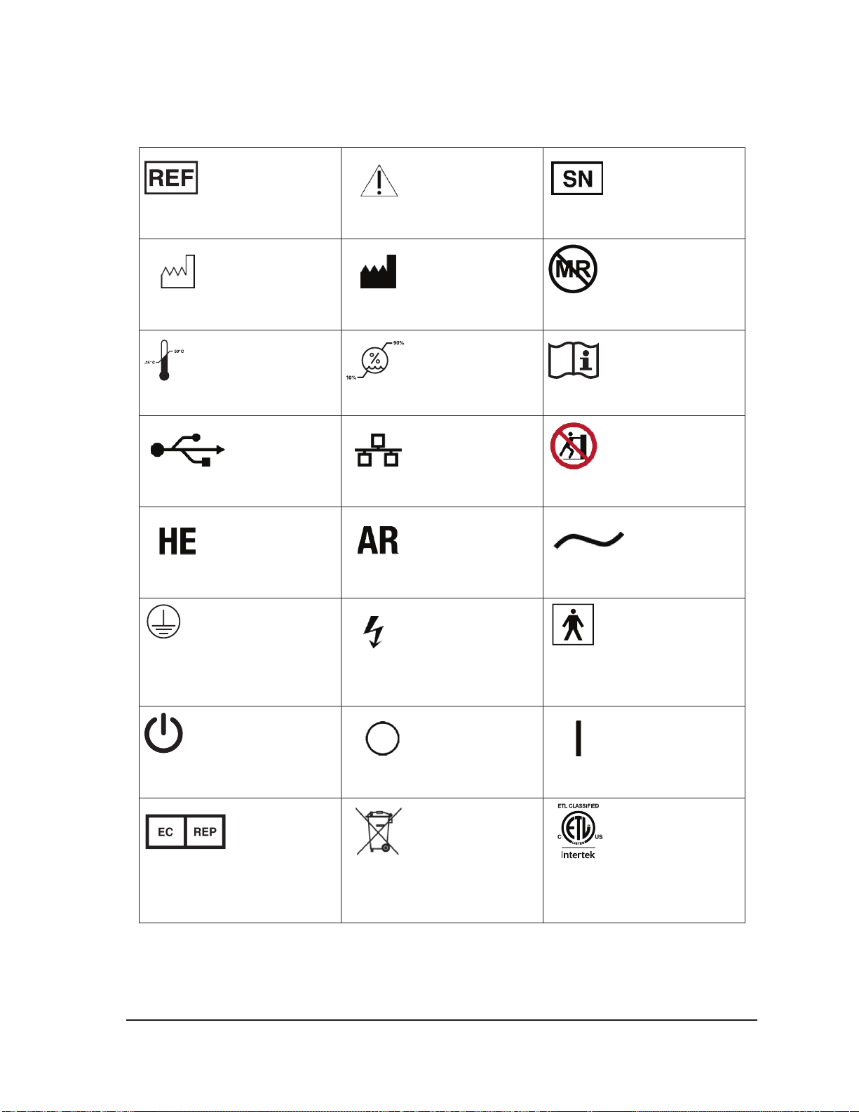
Symbols
1
Catalog Number
1
Date of Manufacture
1
Temperature Limitation
3
USB Port
5
1
Caution
1
Manufacturer
1
Humidity Limitation
4
Ethernet Port
5
1
Serial Number
2
MR Unsafe
1
Consult Instructions for Use
3
Do Not Push
4
Helium Gas
4
Protective Earth
4
Power Switch
1
Authorized Representative in
the European Community
Argon Gas
4
Unsafe Voltage. Electrical
contacts greater than 40 V AC
4
Power O
6
Do Not Discard
Return to Galil Medical at end
of service life
Alternating Current
4
Type BF Applied Part
4
Power On
7
ETL Product Listing
Visual-ICE™ Cryoablation System
ix
Page 12

8
only
Caution: Federal (USA) law
restricts this device to sale by
or on the order of a physician.
Footnotes
1. EN ISO 15223-1:2016 Medical devices –Symbols to be used with medical device labels,
labelling and information to be supplied – Part 1: General requirements
2. ASTM F 2503 – 13 Standard Practice for Marking Medical Devices and Other Items for
Safety in the Magnetic Resonance Environment
3. USB Implementors Forum, Inc. standard icon.
4. IEC TR 60878-3: 2015 Graphical symbols for electrical equipment in medical practice
5. Symbols created by Galil Medical based on the symbols for Helium and Argon in the
Periodic Table of Elements.
6. EN 50419:2006 Marking of electrical and electronic equipment in accordance with article
11(2) of Directive 2002/96/EC (WEEE)
7. ETL Product Listing mark indicates the product is in compliance with North American
product safety standards. Compliance is determined through testing and certication by
Intertek Group plc.
8. USA Code of Federal Regulations 21 CFR Part 801 (§ 801.109(b)(1))
x User Manual
Page 13

1 SYSTEM OVERVIEW
WARNING. A thorough understanding of the technical principles, clinical applications,
and risk associated with cryoablation procedures is necessary before using this product.
Use of this device is restricted to use by or under the supervision of physicians trained in
cryoablation procedures with a Galil Medical Cryoablation System.
CAUTION. All new users must be trained on the use of the Visual-ICE™ Cryoablation System
and cryoablation procedures prior to operating the system. Contact your local Galil Medical
representative to schedule training.
CAUTION. Carefully read all instructions prior to use. Failure to observe all warnings and
precautions may result in complications.
1.1 Brief Description
The Visual-ICE Cryoablation System is a mobile system intended for cryoablative tissue destruction
using a minimally invasive procedure. The system is computer-controlled with a touch screen
user interface that allows the user to control and monitor the procedure. The proprietary i-Flow™
Technology controls the system’s gas ow to maintain consistent gas ow rates for the strongest
possible ice, and to optimize performance for simultaneous activation of multiple needles. Innovative
gas dryers produce consistent iceballs and boost freezing performance for all needles.
The therapy delivered by the system is based on the Joule-Thomson eect displayed by compressed
gases. The Joule-Thomson eect is a change in the temperature of a compressed gas as it ows
through a narrow orice and expands to a lower pressure. Certain gases, such as argon, decrease
in temperature due to the Joule-Thomson eect, while other gases, such as helium, increase in
temperature.
The Visual-ICE System uses high-pressure argon gas that circulates through closed-tip cryoablation
needles to induce tissue freezing. Active tissue thawing is achieved by circulating helium gas through
the needles or, alternatively, by the use of a heating element inside the cryoablation needle which
can be energized to cause thawing (i-Thaw™ Technology). The Visual-ICE System also controls the
heating element inside CX-type needles to provide active helium-free thawing (i-Thaw or FastThaw™)
and track ablation (Cautery).
When multiple cryoablation needles are placed into or near the target tissue and freezing is initiated,
an iceball grows around the distal end of the needle shafts. In time, the iceballs coalesce and
completely engulf the target tissue. An important benet of cryoablation is that imaging procedures,
such as ultrasound and CT, are able to display the location and size of the iceball. This benet of
cryoablation is used for proper control of the therapy. During use, the procedure must be monitored
via image guidance to ensure adequate tissue coverage and to avoid damage to adjacent structures.
In addition to image guidance, Galil Medical provides temperature sensors to aid in monitoring tissue
temperature near the target site and adjacent critical structures. These temperature sensors can
provide quantitative data to supplement the qualitative information provided by the imaging modality.
Needle tip temperature display for CX-type needles provides a visual means to monitor needle
performance.
Tissue ablation is achieved by repeated freeze and thaw cycles with both freezing and thawing
contributing to cell death. Generally, multiple freeze-thaw cycles are used to achieve complete
destruction of the target tissue.
Visual-ICE™ Cryoablation System
1-1
Page 14

1.2 Intended Use
The Galil Medical Visual-ICE Cryoablation System is intended for cryoablative destruction of tissue
during minimally invasive procedures; various Galil Medical accessory products are required to
perform these procedures. The Visual-ICE System is indicated for use as a cryosurgical tool in the
elds of general surgery, dermatology, neurology (including cryoanalgesia), thoracic surgery (with
the exception of cardiac tissue), ENT, gynecology, oncology, proctology, and urology. This system is
designed to destroy tissue (including prostate and kidney tissue, liver metastases, tumors, and skin
lesions) by the application of extremely cold temperatures.
1.3 How Supplied
The Visual-ICE System is supplied non-sterile. Galil Medical accessory products required to perform
the cryoablation procedure are supplied separately.
1.3.1 Contents
• Visual-ICE Cryoablation System
• Visual-ICE Cryoablation System User Manual: The User Manual describes the system and
provides instructions for system operation and maintenance.
• Visual-ICE Cryoablation System Quick Reference Guide: The Quick Reference Guide
summarizes key steps in system operation.
• USB ash drive (4 GB) within an attached pouch: The Galil Medical USB ash drive is used to
transfer procedure reports to a customer’s computer for saving or printing.
• High-pressure argon gas supply line with attached pressure gauge
o To accommodate procedure room variations, the gas supply line is available in alternative
lengths to connect the argon cylinder to the Visual-ICE Console. Reference Table 8-1.
• High-pressure helium gas supply line with attached pressure gauge
o To accommodate procedure room variations, the gas supply line is available in alternative
lengths to connect the helium cylinder to the Visual-ICE Console. Reference Table 8-1.
• Optional EZ-Connect2 Dual Cylinder Adapter: is an optional device used to connect two
gas cylinders in tandem to the Visual-ICE MRI System. The dual cylinder adapter consists of
a four-way adapter assembly with argon pressure gauge and long gas supply line with system
connection, short gas supply line with cylinder connection. Reference 4.5.3 for instructions on
using the EZ-Connect2 Adapter.
• Console cover: Protects the Console from dust, water, and debris during storage and
transportation
• Ethernet cable (3 m): The Ethernet cable is used to connect the Visual-ICE MRI Console to
a Galil Medical remote server for uploading reports and diagnostic data and for downloading
software updates.
1-2 User Manual
Page 15

1.3.2 Accessory Products Used to Conduct Cryoablation Procedures
The following items used with the Visual-ICE System are sterile, single-use only devices. Do not resterilize or reuse.
• Galil Medical Cryoablation Needles: The Visual-ICE System is used only with Galil Medical
cryoablation needles. The cryoablation needles are available in a range of congurations that
produce various iceball sizes and shapes, allowing the clinician to match the needles to the
desired ablation zone. The cryoablation needles are supplied sterile in procedure kits or in needle
kits.
• Cryoablation Needle Labels
• Galil Medical Multi-Point Thermal Sensor™ (MTS): The Multi-Point Thermal Sensors (MTS)
contain four sensor locations along the distal shaft of the needle to monitor temperature near the
target site and adjacent critical structures. The cryoablation needles and MTS are supplied sterile
in procedure kits or in needle kits.
• Galil Medical Urethral Warming Set: The single use, disposable Urethral Warming Set is the
conduit that circulates warm saline through the urethra during a prostate cryoablation procedure.
• CIVCO Percutaneous Instrument Template
The following items used with the Visual-ICE System are re-usable and should be cleaned and/or
sterilized in accordance with the Instructions for Use that accompanies each product.
• Galil Medical Prostate Procedure Template: The Prostate Procedure Template is used to
guide needle placement during a prostate cryoablation procedure.
• IV Pole and Bracket for use with a uid warmer and pump system
The following items are needed to conduct cryoablation procedures and are not available from Galil
Medical.
• Argon gas cylinder(s)
• Helium gas cylinder(s) if using helium for thawing
NOTE: The argon and helium gases must meet the purity requirements specied in Section 8.4.
• A uid warmer and pump system when using the Galil Medical Urethral Warming Set
Galil Medical recommends the use of a sterile drape (customer supplied) to cover the touch screen if
the system will be operated by members of the sterile team.
1.3.3 Storage
Store the Visual-ICE System in a cool, dry, secure location. Storage conditions should be within
-15°C to +50°C and 10% to 90% relative humidity.
Visual-ICE™ Cryoablation System
1-3
Page 16

1.4 Indications
The Visual-ICE Cryoablation System is indicated for use as a cryosurgical tool in the elds of general
surgery, dermatology, neurology (including cryoanalgesia), thoracic surgery (with the exception of
cardiac tissue), ENT, gynecology, oncology, proctology, and urology. This system is designed to
destroy tissue (including prostate and kidney tissue, liver metastases, tumors, and skin lesions) by
the application of extremely cold temperatures.
The Visual-ICE Cryoablation System has the following specic indications:
• Urology Ablation of prostate tissue in cases of prostate cancer
and Benign Prostate Hyperplasia (BPH)
• Oncology Ablation of cancerous or malignant tissue and benign
tumors, and palliative intervention
• Dermatology Ablation or freezing of skin cancers and other cutaneous
disorders
Destruction of warts or lesions, angiomas, sebaceous
hyperplasia, basal cell tumors of the eyelid or canthus
area, ulcerated basal cell tumors, dermatobromas, small
hemangiomas, mucocele cysts, multiple warts, plantar
warts, actinic and seborrheic keratosis, cavernous
hemangiomas, peri-anal condylomata, and palliation of
tumors of the skin
• Gynecology Ablation of malignant neoplasia or benign dysplasia of
the female genitalia
• General surgery Palliation of tumors of the rectum, hemorroids, anal
ssures, pilonidal cysts, and recurrent cancerous lesions,
ablation of breast broadenomas
• ENT Palliation of tumors of the oral cavity and ablation of
leukoplakia of the mouth
• Thoracic surgery (with the exception of cardiac tissue)
• Proctology Ablation of benign or malignant growths of the anus or
rectum, and hemorroids
1.5 Contraindications
There are no known contraindications specic to the use of the Galil Medical Visual-ICE Cryoablation
System.
1-4 User Manual
Page 17

1.6 Warnings
• Do not use this device for any purpose other than the stated intended use and indications for use.
• A thorough understanding of the technical principles, intended use, indications for use and
risk associated with cryoablation procedures is necessary before using this product. Use of
this device is restricted to use by or under the supervision of physicians trained in cryoablation
procedures with a Galil Medical cryoablation system.
• Do not use a Visual-ICE Cryoablation System near magnetic resonance imaging (MRI)
equipment.
• Do not start a cryoablation procedure before verifying that the Visual-ICE System and all ancillary
equipment are fully operational.
• Verify that the Ethernet cable is disconnected prior to starting a cryoablation procedure. Do not
connect the Ethernet cable during a cryoablation procedure.
• Do not use the Visual-ICE Cryoablation System if the system is visibly damaged, exposing any
internal components or sharp edges.
• Have sucient gas (argon / helium) available to conduct the planned cryoablation procedure: the
number and type of needles, gas cylinder size, pressure and rate of gas ow aect the required
gas volume.
• Secure the safety cable at the end of the gas supply line to the console bracket on the Visual-ICE
System before connecting the gas supply line to the gas inlet. The safety cables provide backup
protection if the gas supply lines become inadvertently disconnected from the system.
• Lock the wheels on the Visual-ICE System prior to using the system to avoid inadvertent
movement of the system during a procedure.
• Each needle must be locked into a needle channel before initiating a cryoablation procedure to
avoid the risk of forceful ejection of the needles from the system while under gas pressure.
• Before the patient is anesthetized, the Needle Integrity and Functionality Tests on the cryoablation
needles must be completed successfully to verify proper needle operation.
• Do not touch the chassis of the Visual-ICE Cryoablation System while touching the patient to
avoid the risk of shocking the patient if an inadvertent electrical fault exists.
• Do not pull on the power cord. Grasp the plug, not the power cord, to disconnect the device from
the wall socket.
• Do not modify the Visual-ICE Cryoablation System in any way. Only authorized Galil Medical
personnel or Galil Medical-trained authorized personnel are to service a Visual-ICE System.
• Do not touch the screen if the touch-screen monitor goes blank for more than ve (5) seconds
during a procedure. Immediately turn o power to the system and end the procedure to avoid
inadvertent activation of needles.
• High-pressure gas is dangerous if handled improperly. Local laws and safety rules regarding
pressurized gas systems, reservoirs and components should always be observed.
• The Visual-ICE Cryoablation System should not be operated in the presence of ammable fumes,
e.g., ammable anesthetics or volatile substances.
• The Visual-ICE Cryoablation System should be inspected and serviced periodically according
to the system specications. Service must be performed by authorized service engineers.
Reference Section 6 for system care and maintenance information.
Visual-ICE™ Cryoablation System
1-5
Page 18

1.7 Precautions
1.7.1 General
• Training on appropriate use of the Visual-ICE Cryoablation System is required prior to conducting
a cryoablation procedure.
• The physician is solely responsible for all clinical use of the cryoablation system and for any
results obtained by use of the system. The physician makes all clinical decisions prior to and
throughout the cryoablation procedure based upon his/her professional opinion.
• The Visual-ICE System and the user interface are non-sterile. Contact with any part of the
system or the user interface by a member of the sterile team requires use of customer supplied
sterile accessories, such as a sterile drape.
• Galil Medical recommends having backup argon cylinders available for each treatment to ensure
sucient gas is available to complete a treatment.
• Do not use the Visual-ICE Cryoablation System if any moisture or condensation is present on the
surfaces of the system. Powering up the system containing moisture or condensation could result
in permanent damage to the electrical boards, causing the system to be inoperable.
• Direct the high-pressure gas supply lines toward the oor and secure the lines with the clips
located on the rear of the Visual-ICE System to minimize the potential for tripping.
• Conrm that the Manual Vent Valve is closed before connecting the gas lines to the system.
• Continuously monitor the cryoablation procedure using image guidance such as direct
visualization, ultrasound, or Computed Tomography (CT) to ensure adequate tissue coverage and
to avoid damage to adjacent structures.
• Galil Medical recommends using the Galil Medical Multi-Point Thermal Sensors (MTS) to monitor
the freeze / thaw temperatures for the intended treatment protocol and to monitor temperatures in
the adjacent organs and structures.
• Ensure that the MTSs are functioning properly before inserting into the patient by verifying that
they are reading a reasonable room temperature.
• Cryoablation freezes and destroys tissue. To limit this eect to only the target ablation area, the
physician must determine the means to protect adjacent organs and structures.
• Position the Visual-ICE System in a manner to avoid draping needle tubing across the patient.
Needle tubing may become extremely cold when conducting freeze cycles during a cryoablation
procedure. It is important that a patient’s skin is protected from direct contact with needle tubing
to avoid the potential for thermal injury to the patient. Ensure an appropriate insulating barrier is
placed as needed (such as towels) or other method is employed to prevent needle tubing from
touching a patient’s skin.
• No data regarding cryoablation in combination with other therapies is available from Galil Medical.
• Do not set heavy objects on the monitor when in the down position or on the monitor storage
basin when the monitor is in the up position. The weight limit is 9 kg (20 lbs).
• Portable and mobile radiofrequency (RF) communications equipment can aect the Visual-ICE
Cryoablation System, causing it to operate improperly. Keep such equipment away from the
system (reference Section 8.7).
• Use only Galil Medical supplied components and accessories with the Visual-ICE System.
• Do not connect any other USB equipment to the Visual-ICE Cryoablation System USB port.
• Use Galil Medical USB ash drive only to export reports or update software. Other data or
software may corrupt the Visual-ICE System.
1-6 User Manual
Page 19

• Do not use a USB extension cable to connect the USB ash drive to the USB port. Connect the
Galil Medical USB ash drive directly to the USB port provided on the Visual-ICE System. Use of
a USB extension cable may result in electromagnetic emissions exceeding regulatory limits.
• Do not perform a cryoablation procedure with the Ethernet cable plugged into the Visual-ICE
System to avoid the potential risk of corrupting the system software. Only use the Ethernet cable
when downloading software updates or when uploading reports to the Galil server.
• Any person who connects external equipment to the Ethernet or USB ports has formed a Medical
Electrical System and is therefore responsible for the system to comply with the requirements. If
in doubt, contact a qualied medical technician or your local representative or Galil Medical.
1.7.2 Handling
• Maneuver the Visual-ICE System by pulling on the system using the rear handle.
• Handle the Visual-ICE Cryoablation System with care. Rough handling may damage the system
and cause it to become inoperable.
• Do not bend or kink the gas supply lines. Sharp bends or kinks may compromise the integrity of
the gas supply lines.
• Do not tilt the Visual-ICE Cryoablation System.
• Lift the Visual-ICE System to clear any threshold that is higher than 2 cm. Two people, one on
each side, should use the handles to lift the system.
• Do not roll the Visual-ICE System over the gas supply lines; such activity may damage the lines.
• The Visual-ICE Cryoablation System is non-sterile. When attaching cryoablation needles to the
system, do not contaminate the sterile eld or the sterile cryoablation needle. Avoid contact with
the distal portion of the cryoablation needle.
• Position the Visual-ICE System in a manner to avoid draping needle tubing across the patient.
Needle tubing may become extremely cold when conducting freeze cycles during a cryoablation
procedure. It is important that a patient’s skin is protected from direct contact with needle tubing
to avoid the potential for thermal injury to the patient. Ensure an appropriate insulating barrier is
placed as needed (such as towels) or other method is employed to prevent needle tubing from
touching a patient’s skin.
• Use care to avoid electrostatic discharge (ESD) events when removing the cover from the Visual-
ICE System. Galil Medical recommends that the operator touch one or more metal parts on the
rear of the system prior to touching anything on the Needle Connection Panel.
• Do not store liquids in the storage compartment. The storage compartment is not water tight.
1.7.3 During Use
• Use image guidance to monitor needle insertion, iceball formation, needle positioning, and
removal.
• Use Freeze and Thaw operations only when the needle is placed in the target tissue.
• Failure to operate the Visual-ICE System within the working pressure limits indicated on the user
interface (Table 4-2) may aect the cryoablation procedure.
• Needle handles frost during freezing. Avoid prolonged contact with frosted portions of a needle
handle to avoid unintended thermal tissue damage to the patient or clinician.
Visual-ICE™ Cryoablation System
1-7
Page 20

• Position the Visual-ICE System in a manner to avoid draping needle tubing across the patient.
Needle tubing may become extremely cold when conducting freeze cycles during a cryoablation
procedure. It is important that a patient’s skin is protected from direct contact with needle tubing
to avoid the potential for thermal injury to the patient. Ensure an appropriate insulating barrier is
placed as needed (such as towels) or other method is employed to prevent needle tubing from
touching a patient’s skin.
• Active thawing produces heat along the distal needle shaft. Use care to avoid thermal injury to
non-targeted tissues.
• Track ablation produces heat along the distal needle shaft and may warm the needle handle.
Use care to avoid thermal injury to non-targeted tissues. When conducting FastThaw or when
conducting Cautery for Track Ablation, be alert for the Active Zone Indicator as the needle is
withdrawn to prevent unintended tissue damage from the hot needle.
• If a needle appears to be blocked, press the Thaw button to thaw the needle for at least one
minute to clear the blockage.
• Take precautions to avoid potential electrostatic discharge. If an electrostatic discharge occurs
after touching the monitor, the screen may icker and MTS temperature readings may be
inaccurate for a few seconds. The system will remain functional and the monitor will refresh
momentarily.
1.7.4 After Use
• Depressurize the system after the cryoablation procedure is completed (reference Section 4.4).
• Warn people near the system about loud noise before manually depressurizing the system.
• Cut the needle and MTS tubing and dispose of used needle and MTS in a biohazard container in
accordance with hospital and safety regulations.
• Clean the Visual-ICE System per the instructions in Section 6.2. Do not use cleaning agents such
as Betadine or bleach solution, which may damage the touch screen.
• To avoid confusion at the beginning of a new procedure, ensure that the
o Manual Vent Valve is closed
o Argon Shuto Valve is in the GAS ON position
1-8 User Manual
Page 21

1.8 Potential Adverse Events
Potential adverse events which may be associated with the use of cryoablation may be organ
specic or general and may include, but are not limited to abscess, adjacent organ injury,
allergic/anaphylactoid reaction, angina/ coronary ischemia, arrhythmia, atelectasis, bladder neck
contracture, bladder spasms, bleeding/hemorrhage, creatinine elevation, creation of false urethral
passage, cystitis, death, deep vein thrombosis (DVT), delayed/non healing, diarrhea, disseminated
intravascular coagulation (DIC), ecchymosis, edema/swelling, ejaculatory dysfunction, erectile
dysfunction (organic impotence), fever, stula, genitourinary perforation, glomerular ltration rate
elevation, hematoma, hematuria, hypertension, hypotension, hypothermia, idiosyncratic reaction,
ileus, impotence, infection, injection site reaction, myocardial infarction, nausea, neuropathy,
obstruction, organ failure pain, pelvic pain, pelvic vein thrombosis, penile tingling/numbness,
perirenal uid collection, pleural eusion, pneumothorax, probe site paresthesia, prolonged chest tube
drainage, prolonged intubation, pulmonary embolism, pulmonary insuciency / failure, rectal
pain, rectourethral stula, renal artery/renal vein injury, renal capsule fracture, renal failure, renal
hemorrhage, renal infarct, renal obstruction, renal vein thrombosis, scrotal edema, sepsis, skin burn/
frostbite, stricture of the collection system or ureters, stroke, thrombosis/thrombus/embolism, transient
ischemic attack, tumor seeding, UPJ obstruction/injury, urethral sloughing, urethral stricture,
urinary stula, urinary frequency/urgency, urinary incontinence, urinary leak, urinary renal leakage,
urinary retention/oliguria, urinary tract infection, vagal reaction, voiding complication including irritative
voiding symptoms, vomiting, wound complication, and wound infection.
Visual-ICE™ Cryoablation System
1-9
Page 22

This page intentionally left blank.
1-10 User Manual
Page 23

2 SYSTEM DESCRIPTION
The Visual-ICE™ Cryoablation System is a mobile cryoablation system that contains ten needle
connection channels (each supporting two needle ports), four Multi-Point Thermal Sensor sockets,
one argon inlet connector, one helium inlet connector, a recessed 19-inch touch screen monitor, a
mouse track pad, two USB ports, and an Ethernet port. The system hardware and operating software
are housed within the system.
The system is mounted on four swivel caster wheels for system mobility. The system contains a
three-way brake pedal mechanism in front to immobilize the two front wheels of the system during a
procedure and to provide directional control during movement of the system. The rear wheels have
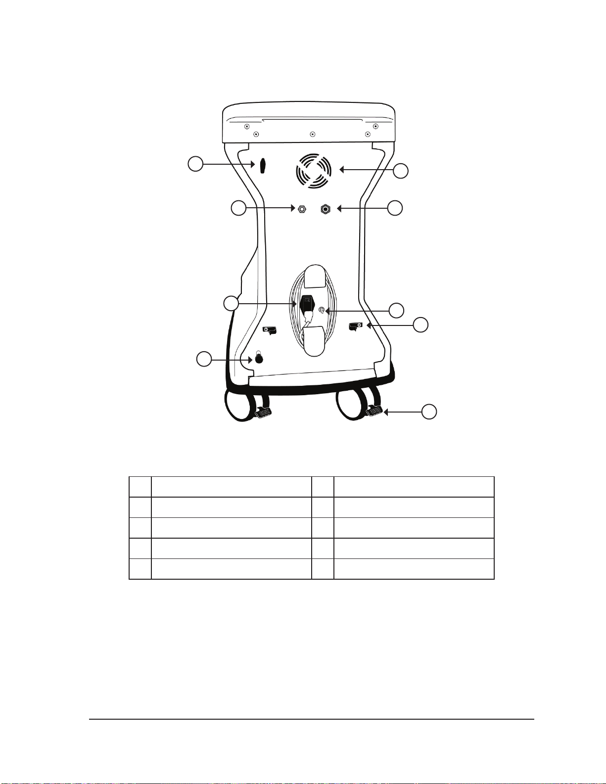
individual brake pedals. Gas supply line clips at the rear of the system (Figure 2-2) are used to direct
the gas supply lines toward the oor, minimizing tripping hazards. A compartment in the lower section
provides storage for system accessories.
Visual-ICE™ Cryoablation System
2-1
Page 24
4
1
2
3
5
6
7
8
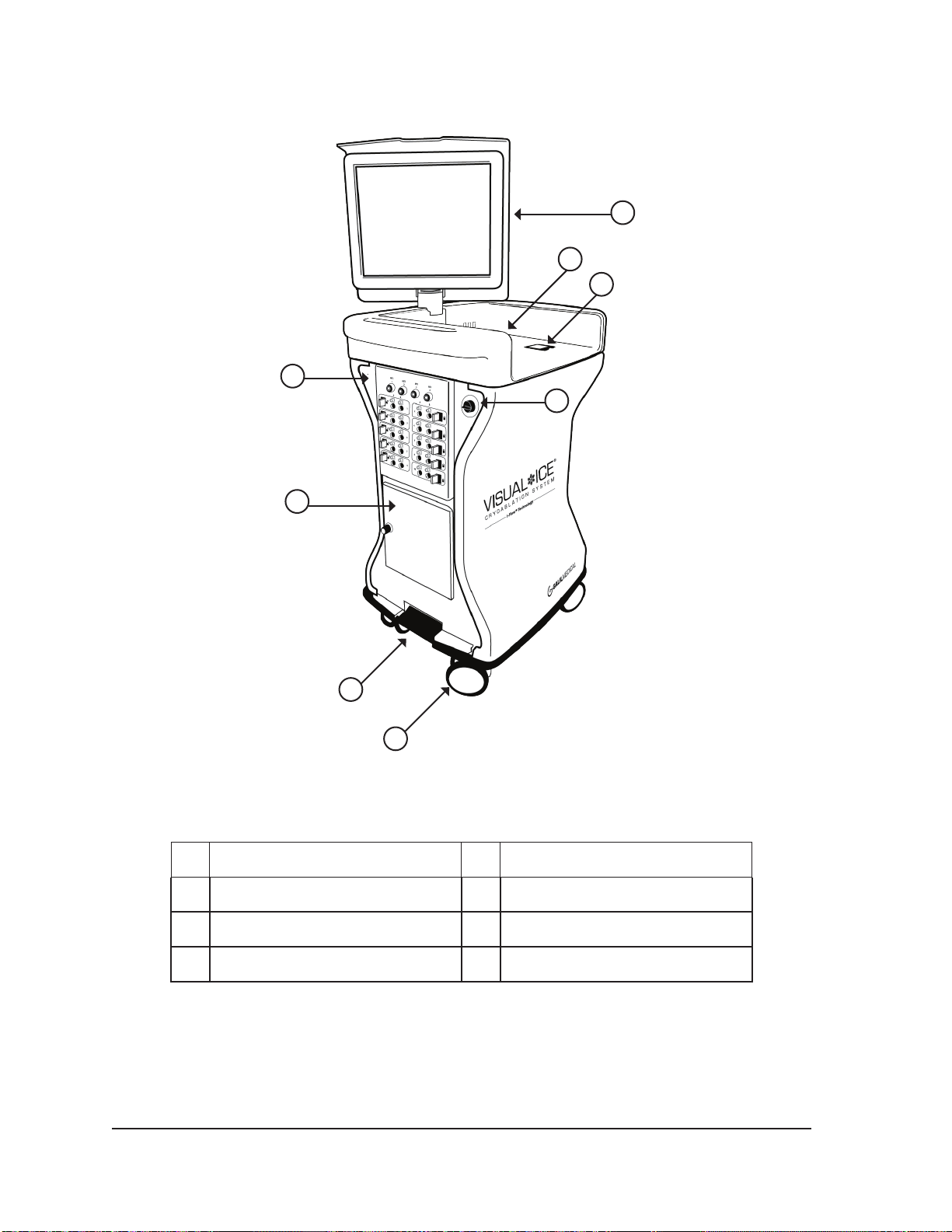
Figure 2-1. Visual-ICE Cryoablation System Front View
1 Touch Screen Monitor 2 Monitor Storage Compartment
3 Mouse Track Pad 4 Needle Connection Panel
5 Power Control Knob 6 Storage Compartment
7 Brake Pedal 8 Wheels (casters)
2-2 User Manual
Page 25
1
2
3
6
9
Figure 2-2. Visual-ICE Cryoablation System Rear View
1 Argon Shuto Valve 2 Cooling Fan
4
7
8
10
3 Argon Inlet Connector 4 Helium Inlet Connector
5 Cord Wrap Bracket 6 Power Switch
7 Ground Post (select countries) 8 Gas Supply Line Clip
9 Manual Vent Valve 10 Rear Wheel Brake Pedal
2.1 Touch Screen Monitor
The cryoablation procedure is controlled through the use of the touch screen monitor. The monitor
can be tilted and rotated to provide the optimal viewing and operating angle for the user. The touch
screen monitor includes a virtual on-screen English QWERTY keyboard for entering procedure
related data and may be operated with either a stylus or by nger touch. The monitor folds at into the
top of the unit for storage.
NOTE: The touch screen may need to be calibrated to obtain accurate responses from the touch
screen commands (reference Section 5.1)
Visual-ICE™ Cryoablation System
2-3
Page 26
2.2 Communication Ports
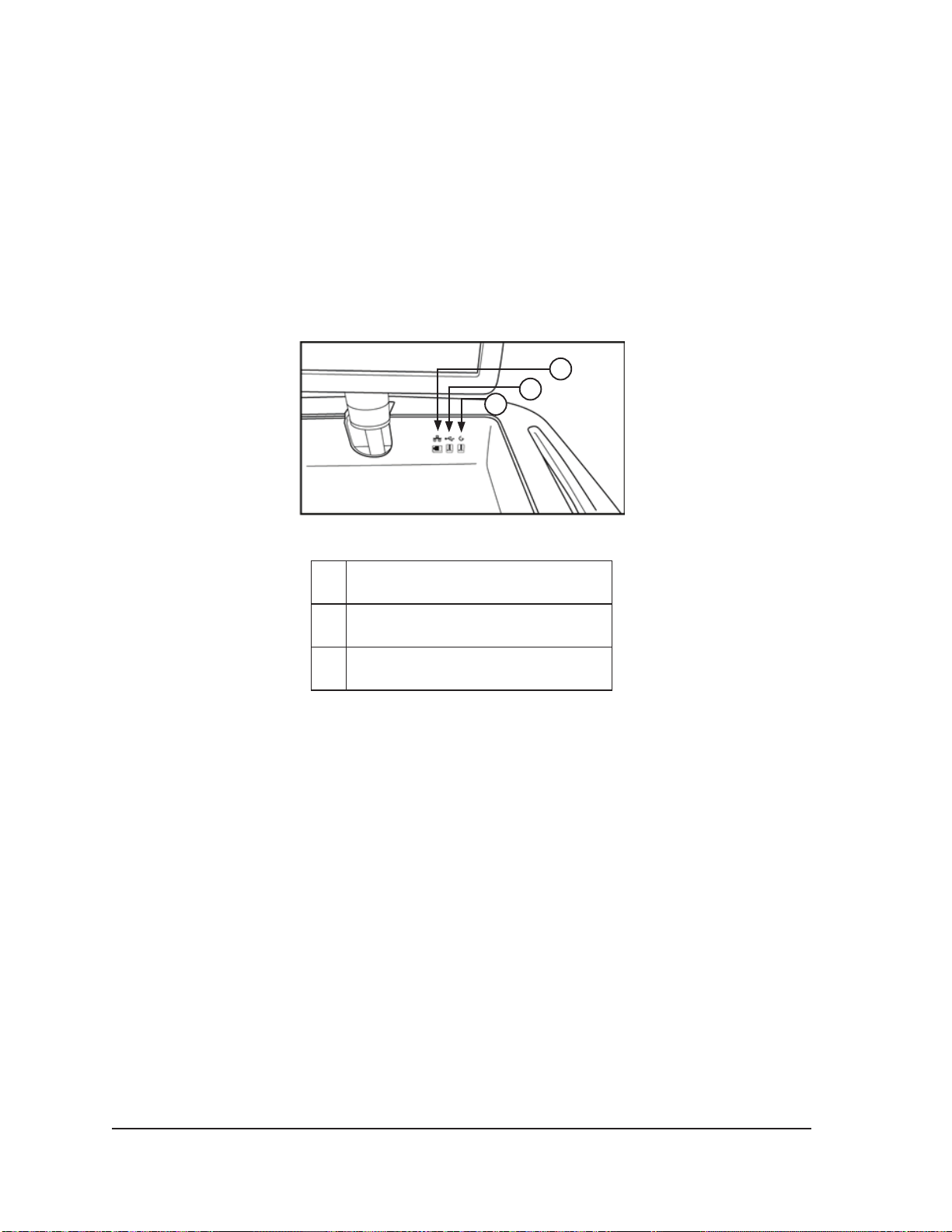
Three communication ports are located on the back panel of the monitor storage compartment
(Figure 2-3).
• The Ethernet port allows connection of the Visual-ICE Cryoablation System to a Galil Medical
remote server for uploading reports and diagnostic data and for downloading software updates
and User Manual updates.
• The USB 2.0 full-speed port allows you to save reports to a Galil Medical USB ash drive for
download to another computer or for printing.
• The USB 2.0 low-speed port is reserved for future system expansion.
1
2
3
Figure 2-3. Monitor Storage Compartment
1 Ethernet Port
2 USB 2.0 Full-speed Port
3 USB 2.0 Low-speed Port
2.3 Mouse Track Pad
The mouse track pad is located within the recessed monitor storage cavity. The mouse track pad
provides an alternative to the touch screen as a means of interacting with the system. Use the track
pad to move and position the cursor on the monitor. To press a button on the screen, position the
cursor over the button and press the left button on the track pad.
2.4 Storage Compartment
The storage compartment may be used to store Visual-ICE System accessories, such as the
gas supply lines and tools. Do not place very heavy objects in the storage compartment. The
weight limit is 23 kg (50 lbs). Do not store liquids in the compartment. Liquids spilled in the storage
compartment may drip into the system; the compartment is not water tight.
2-4 User Manual
Page 27

2.5 Brake Pedal
The brake pedal operates on the front two wheels of the Visual-ICE Cryoablation System. Position
the brake in the UP position to prevent the front two wheels from swiveling during transportation.
Position the brake in the DOWN position to lock the front two wheels into place. When the brake
pedal is in the middle position, the front two wheels are free to roll and swivel. If the ooring is
uneven, it may be necessary to lock the two rear wheels in addition to locking the front wheels. Lock
each rear wheel by using the individual locking pedal on each wheel.
2.6 Argon Shuto Valve
The Argon Shuto Valve is used to turn the gas supply to the Visual-ICE Cryoablation System ON or
OFF. It should be left in the GAS ON position and used to turn OFF argon gas only in an emergency.
2.7 Gas Inlets
The gas supply lines connect the argon and helium gas supply from the respective gas cylinders to
the argon and helium gas inlets. The argon inlet is a plug connector; the helium inlet is a socket
connector.
2.8 Manual Vent Valve
The Manual Vent Valve is used to vent the high pressure gas from the Visual-ICE System if the
automatic venting feature is not used.
Visual-ICE™ Cryoablation System
2-5
Page 28
2.9 Needle Connection Panel
2
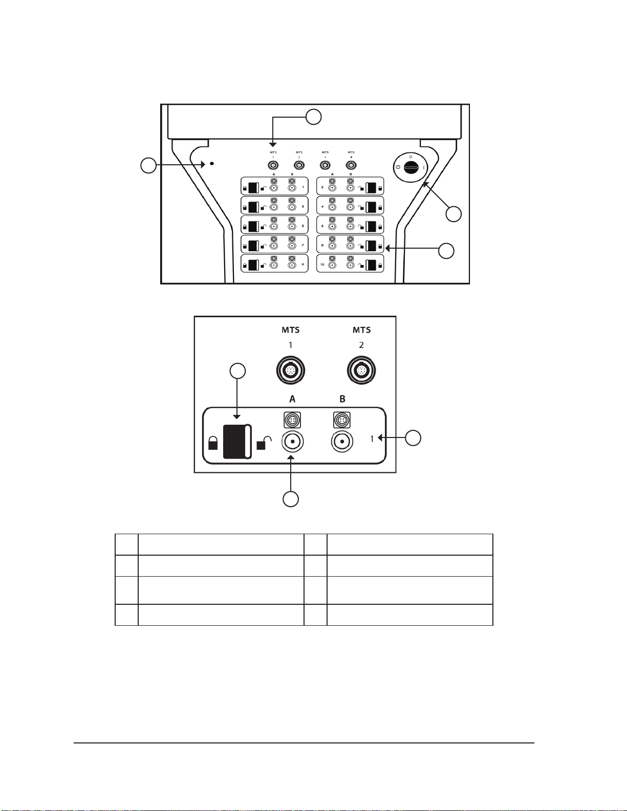
Figure 2-4. Visual-ICE Cryoablation System Needle Connection Panel
5
1
3
4
7
6
Figure 2-5. Visual-ICE Cryoablation System Needle Channel
1 MTS Connection Port 2 Software Reset
3 Power Control Knob 4 Needle Channel
5 Locking Bar 6
7 Channel Number
Needle Port with Electrical
Connection
2.9.1 MTS Connection Ports
Four MTS Connection Ports are located above the Needle Connection Channels. The MTS
connection ports support connection of the Galil Medical Multi-Point Thermal Sensors that are used to
monitor temperature within and near the cryoablation target site.
2-6 User Manual
Page 29

2.9.2 Software Reset
The Software Reset button is used to boot the Visual-ICE Cryoablation System into a recovery mode
if the software becomes corrupted (reference Section 7.1).
2.9.3 Power Control Knob
The Power Control Knob powers ON the Visual-ICE Cryoablation System in preparation for a
procedure.
2.9.4 Needle Channels
The Needle Connection Panel contains ten numbered needle channels; each channel contains two
ports to support connection of up to two cryoablation needles. Each channel operates independently
of all other channels in either freezing or thawing mode. The electrical connection is used for needles
with a memory chip, i-Thaw™, FastThaw™ or Cautery capabilities. The locking bar on each channel
locks the needles into the ports to secure them during the procedure.
Visual-ICE™ Cryoablation System
2-7
Page 30

This page intentionally left blank.
2-8 User Manual
Page 31
3 NAVIGATING THE USER INTERFACE
Throughout the User Manual typeset conventions represent various user interface sections, software
buttons, positions, and steps.
• Software Screen section
• Control button
• ON position
• OPTIONAL = optional or alternate step
The Visual-ICE™ Cryoablation System provides a graphical user interface that facilitates rapid
communication between the user and the system through a touch screen interface.
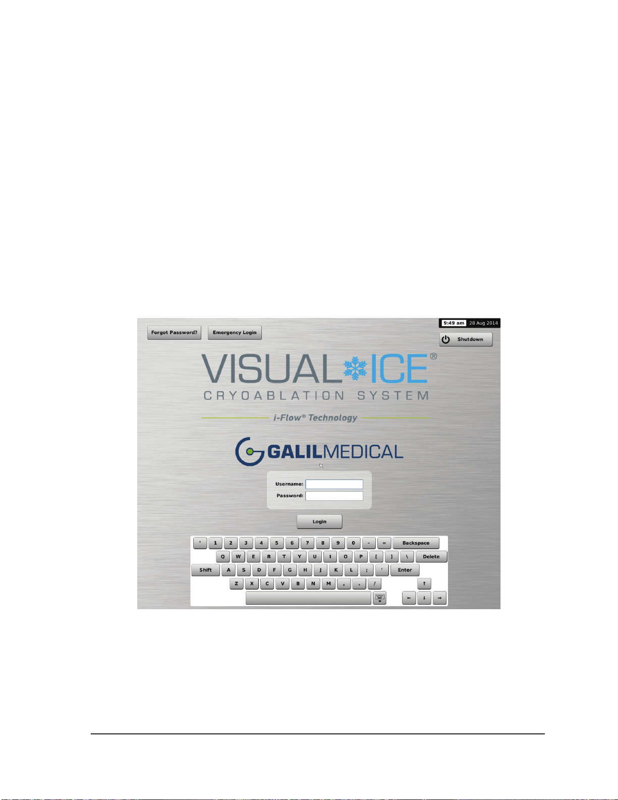
3.1 Login Screen
When the system is powered on, the Login Screen appears after the boot-up process is complete
(reference Section 4.1.1).
Visual-ICE™ Cryoablation System
Screen 3-1. Login Screen
3-1
Page 32
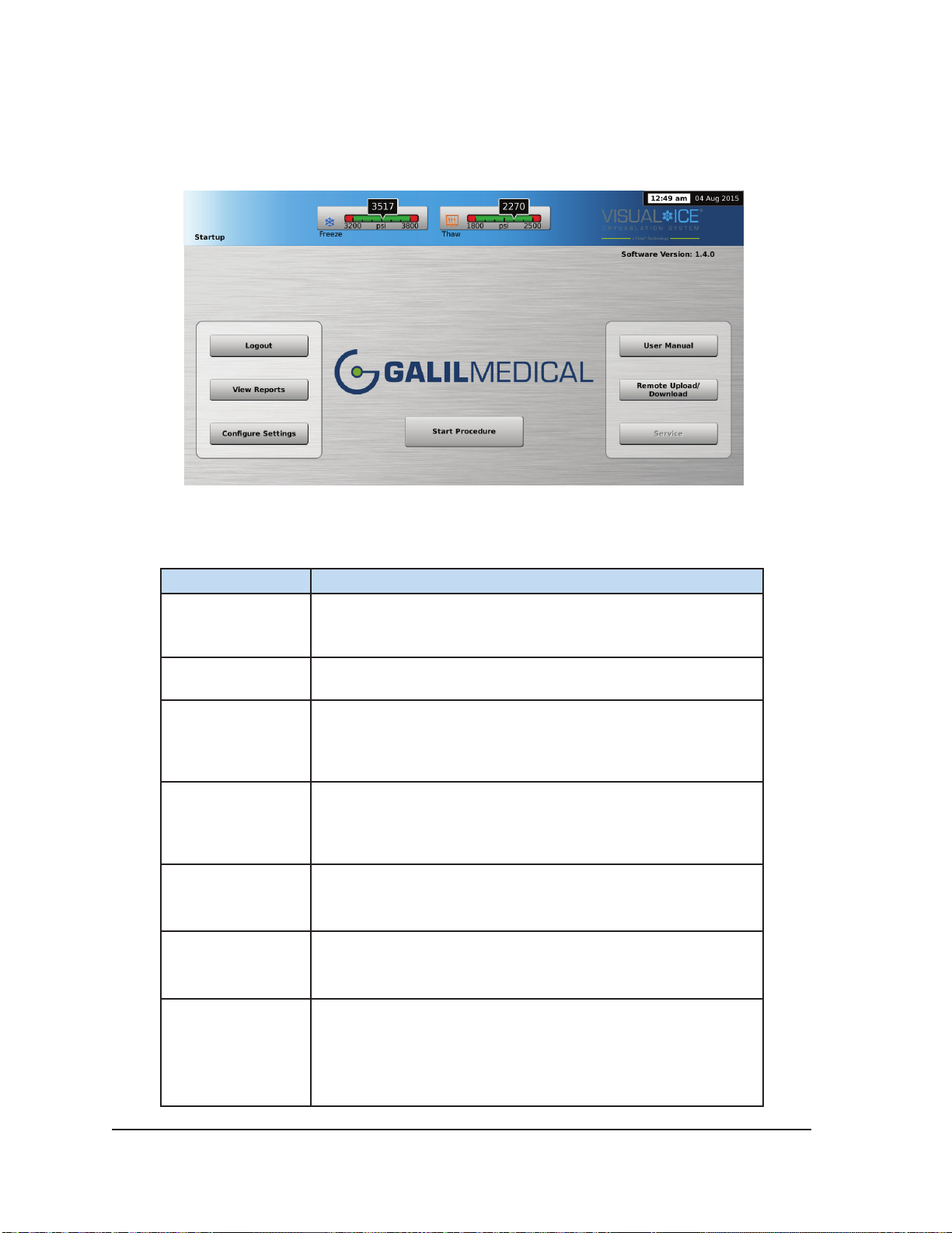
3.2 Startup Screen
After logging into the system, the Startup Screen displays several options.
Screen 3-2. Startup Screen
Table 3-1. Startup Screen Buttons
Button Description
Start Procedure
Logout Log out of the system.
View Reports
Congure
Settings
User Manual
Remote Upload /
Download
Service
Transition to the Procedure Screen to start a cryoablation
procedure.
View the contents of a report and export reports to a Galil
Medical USB ash drive.
NOTE: Administrative users may also delete reports.
Congure various system settings (reference Section 5.1).
NOTE: Some conguration parameters are limited to
administrative and/or service users only.
View information on how to access an electronic version of the
User Manual.
Upload reports and download new software and conguration
les from a Galil Medical server.
Field Service personnel login to modify conguration settings,
perform and record preventive maintenance activities.
NOTE: This option is only available to authorized eld service
personnel.
3-2 User Manual
Page 33
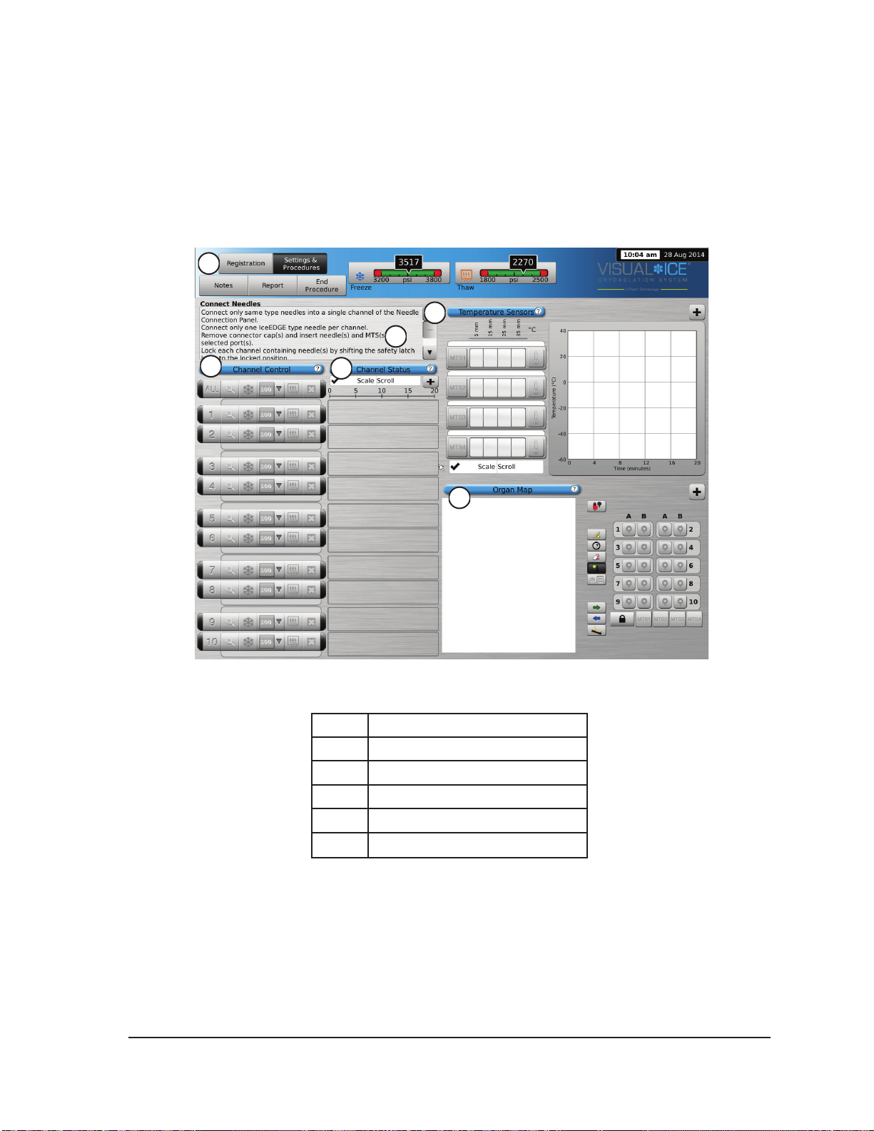
3.3 Procedure Screen
The Visual-ICE System Procedure Screen provides a single-screen view to control and monitor
a cryoablation procedure. The Procedure Screen is divided into sections for the Navigation Tool
Bar, Context Sensitive Help, Channel Controls, Channel Status, Temperature Sensors, and Organ
Map. The title bar of each section on the Procedure Screen provides user selected self-help for that
section.
1
5
2
3
4
6
Screen 3-3. Procedure Screen
1 Navigation Tool Bar
2 Context Sensitive Help
3 Channel Control
4 Channel Status
5 Temperature Sensors
Visual-ICE™ Cryoablation System
6 Organ Map
3-3
Page 34
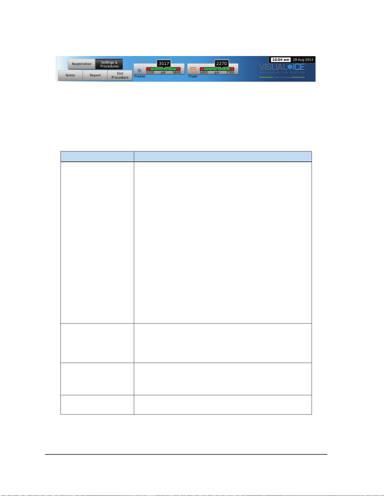
3.3.1 Navigation Tool Bar
Screen 3-4. Navigation Tool Bar
The Navigation Tool Bar contains the Pressure Gauge / Gas Indicator and procedure buttons that
you can select to enter registration information, congure procedure settings, enter procedure notes,
view and export reports, and end the procedure. On occasion, error messages may be displayed in
lieu of the logo.
Table 3-2. Navigation Tool Bar
Button Description
Pressure Gauge / Gas
Indicator
Displays the working pressure of the argon and helium gases
within the system.
NOTE: The Visual-ICE System contains internal regulators
that regulate the gas pressure to appropriate working limits.
The pressure displayed on the Gas Indicator is the internal,
regulated pressure and not the cylinder gas pressure.
Pressing the Pressure Gauge toggles the pressure gauge
to display the estimated procedure time remaining before
the gas cylinders are depleted. The estimated times are
displayed in hours:minutes:seconds. During needle testing,
both pressure gauges display the estimated time remaining.
The initial estimates during needle testing are based on
the assumption that all connected needles are operating
simultaneously at 100% freeze intensity.
The Gas Indicator updates in real-time as needles are
disconnected or additional needles are connected and as
the freeze intensity is adjusted. Pressing the Gas Indicator
toggles the display back to Pressure Gauge.
Registration Provides optional data entry elds to record Patient ID,
Hospital Name, Hospital Address, Physician Name, and
Organ Type. Two custom elds are provided for additional
information. The names of the custom elds can be specied
in the Congure Settings screen (reference Section 5.1)
Notes A location to input text. Selecting this button displays the
on-screen keyboard for data entry. Procedure notes entered
in this location are included in the procedure report (reference
Section 3.2).
Settings and
Procedure
3-4 User Manual
Displays the Procedure Screen to begin a cryoablation
procedure.
Page 35
Button Description
Report Displays a report of all procedure data that has been entered
and captured for the current procedure. The report can be
saved to the Galil Medical USB ash drive. Pressing the
Report button during a procedure displays all procedure
information saved up to that point in time.
End Procedure Ends the current procedure and returns to the Startup Screen.
Pressing this button generates a conrmation request, a
request to save the report, and an option to automatically vent
the system.
3.3.2 Context Sensitive Help
The Context Sensitive Help displays a summary of procedural steps to guide you through a
cryoablation procedure. It is intended to provide only a general overview; step-by-step instructions
are provided in Section 4.1.
3.3.3 User-Selected Self Help
The title bar of each section provides access to additional help information. Press the title bar to
access an explanation of the buttons and elds available in each section of the Procedure Screen.
3.3.4 Channel Controls
Channels 1 through 10 are labeled individually and contain independent controls for Test, Freeze,
Freeze Intensity, Thaw, and Stop. Each individual channel displays the needle type of the needles
connected adjacent to the channel controls (Screen 3-5). The Channel labeled ALL operates all
active channels simultaneously.
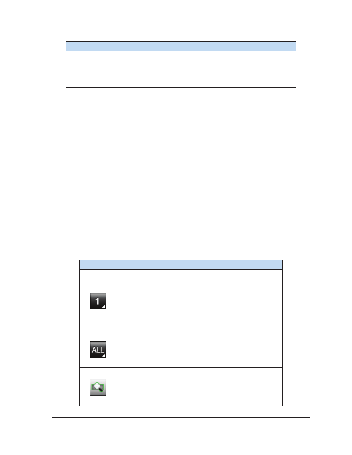
Table 3-3. Channel Controls
Button Description
Channel button – Identies the active channel(s).
Advanced Channel Controls: Pressing and holding the
Channel button provides options to change the needle
type selected for that channel, link two adjacent channels
together for simultaneous operation, and program freeze –
thaw cycles.
Channel labeled ALL – Allows testing, freezing, and thawing
on ALL active channels simultaneously. Press the button for
the desired function (Test, Freeze, or Thaw) on this channel to
activate that function on all needles simultaneously.
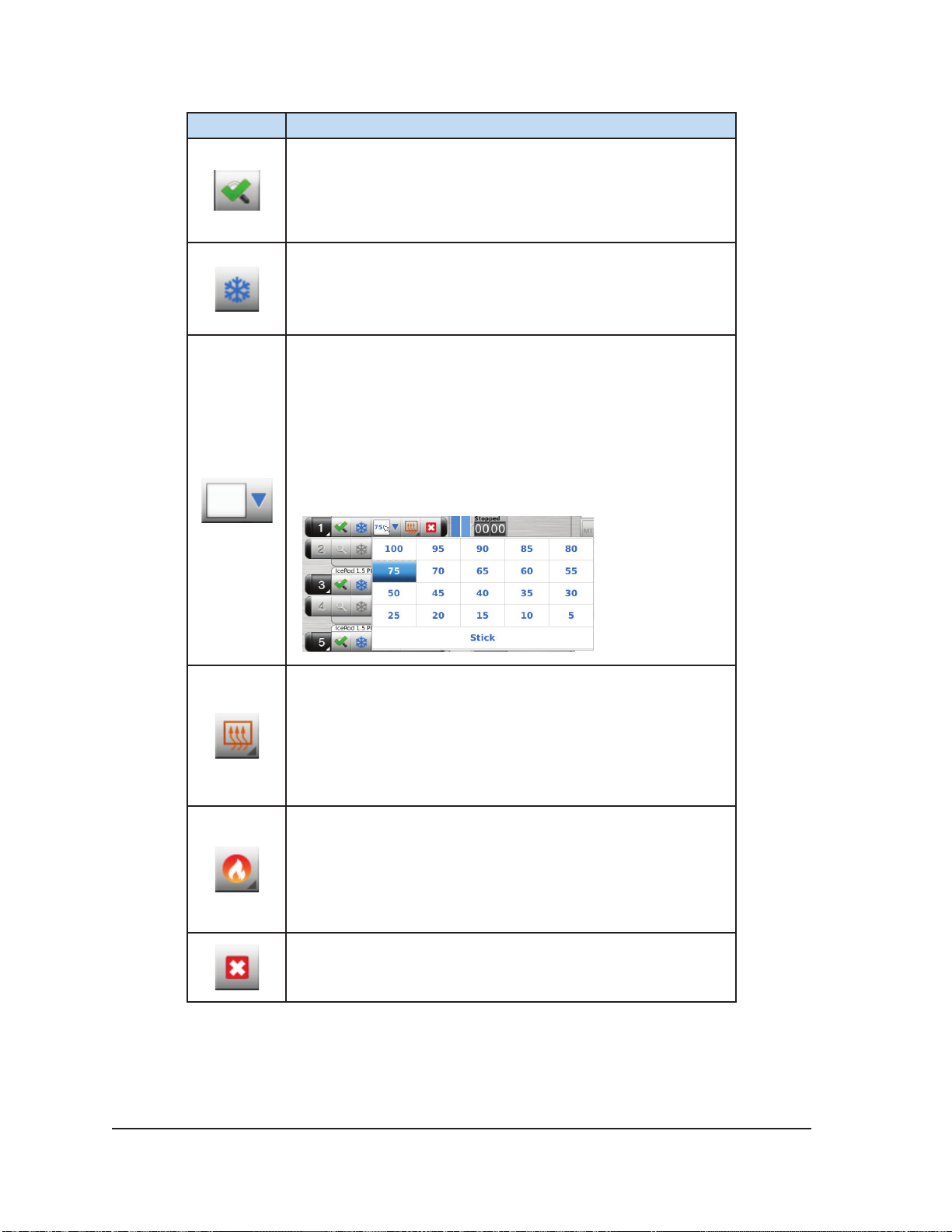
Test button – Begins the Needle Integrity and Functionality
Testing that is required prior to using any cryoablation needle.
No other controls are enabled until needle testing is complete.
Visual-ICE™ Cryoablation System
3-5
Page 36
Button Description
Tested button - Following completion of Needle Integrity and
Functionality Testing, the button displays a check mark and the
remaining control buttons on the channel become active.
Freeze button – Begins a Freeze phase at the selected freeze
intensity.
Freeze Intensity drop-down menu – Provides an option to
adjust the freeze intensity from 100% to 5% or to select “Stick”
intensity.
NOTE: The Visual-ICE System controls freeze intensity by
adjusting the duration of argon ow over each 10 second block
of time (e.g., 30% freeze intensity freezes for 3 seconds and
idles for 7 seconds).
Thaw button – Begins a Thaw phase.
Advanced Thaw Controls: Pressing and holding the Thaw
button provides an option for enabling FastThaw and an
option for enabling track ablation via the Cautery button.
The FastThaw and Cautery functions are available only on
CX-type cryoablation needles.
FastThaw button – Begins a FastThaw phase.
Advanced Thaw Controls: Pressing and holding the
FastThaw button provides an option to change from
FastThaw to i-Thaw. The FastThaw function is available
only on CX-type cryoablation needles.
Stop button – Stops any activity.
3-6 User Manual
Page 37
3.3.5 Channel Status
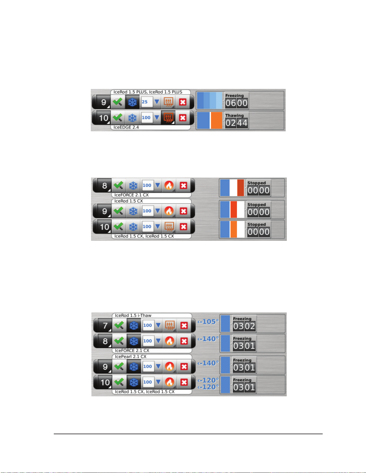
Channel Status shows the status of each freeze, thaw, and idle phase with numeric and color-coded
displays on the progress indicator. Variations in blue shading visually represent the selected freeze
intensity. The Timer button to the right of the progress indicator displays the elapsed time of the
current phase.
Screen 3-5. Channel Controls and Channel Status section
Variations in orange shading visually distinguish active thaw (helium or i-Thaw), FastThaw and
Cautery phases (Screen 3-6).
Screen 3-6. Active Thaw Channel Status section
For i-Thaw and CX-type needles, the Channel Status also displays the internal gas temperature at
the needle tip during freeze phase and the estimated temperature range for the needle shaft during
active thaw phase. The temperature display is updated every 2 seconds.
NOTE: During the needle warming phase for CX-type needles, the channel status will display a
rotating warming indicator
Screen 3-7. Needle Tip Temperature Display
Visual-ICE™ Cryoablation System
3-7
Page 38
3.3.6 Enlarge and Reposition Timers
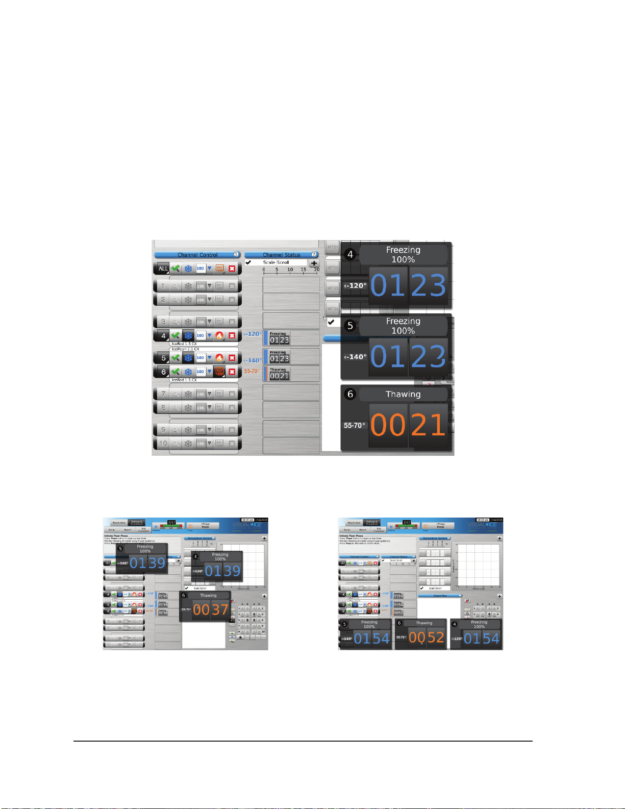
During a needle test, freeze, thaw, or idle phase, press the Timer button to enlarge the timer display
(Screen 3-8). The enlarged Timer displays the channel number in the upper left corner of the timer
window, elapsed time, and, when freezing, the selected freeze intensity. When CX-type needles are
connected, the enlarged timer also displays the internal needle tip temperature during the freeze
phase and the estimated temperature range of the needle shaft during the thaw phase.
NOTE: During the needle warming phase for CX-type needles, the timer will display a rotating
warming indicator.
Timers for three selected channels can be simultaneously enlarged. Press the timer to return it to its
original size.
Screen 3-8. Enlarged Timer
Change the location of an enlarged timer by dragging the timer to a new screen location.
Screen 3-9. Repositioned Enlarged Timers
3-8 User Manual
Page 39
To briey display the time associated with a completed cycle, press the section of the status bar for
the selected operation.
Press the Scale button to adjust the graphical display of the channel status such that all operations
are visible. Press the Scroll button to adjust the graphical display to 5-minute increments; the display
scrolls throughout the procedure.
Press the Maximize button (+) to enlarge the graphical display. Press the Minimize button (-) to
reduce the display to the original size.
3.3.7 Temperature Sensors
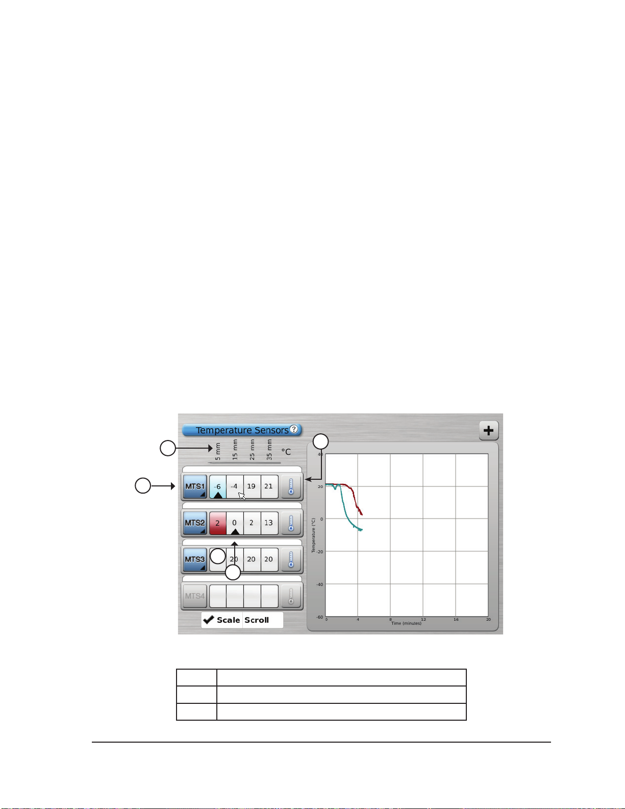
The Temperature Sensors section (Screen 3-10) displays the temperature measured for each sensor
location on the connected MTS needles and a black triangle highlights the coldest temperature on
each MTS.
Temperature vs. Time can be plotted for any four selected sensor locations from the connected MTS
needles. Press the button corresponding to the selected sensor location on an MTS to select that
sensor location to be graphed. Press the respective MTS Channel button to graphically display all
four sensor locations of an individual MTS. The color of the selected temperature sensor location
corresponds to the color of the temperature line on the graph. Press the Thermometer button to
graph the coldest temperature on a selected MTS. Press the Thermometer button again to return to
the original display.
NOTE: A maximum of four sensor locations can be displayed on the graph at any one time. The four
selected sensor locations can be from any of the connected MTS needles.
1
2
5
6
Screen 3-10. Temperature Sensors section
3
1 MTS sensor locations
2 MTS Channel button
3 Thermometer button
Visual-ICE™ Cryoablation System
3-9
Page 40
4 Maximize button
5 Button corresponding to 5 mm sensor location
6 Triangle indicates coldest sensor
Select the Scale button to adjust the graphical display of the temperature measurements such that
the temperature throughout the entire procedure is visible. Select the Scroll button to display a scroll
bar to scroll through the graphical data during the procedure.
To enlarge the Temperature Sensors graphical display press the Maximize button (+). Press the
Minimize button (-) to return the display to the original size.
Advanced Temperature Sensors Controls: Pressing and holding an MTS Channel button provides
an option to set visual alarms when a chosen temperature measurement falls below a desired value
or when the rate of temperature drop is greater than a desired value. This advanced control also
provides an option to label the MTS location (reference Section 4.8).
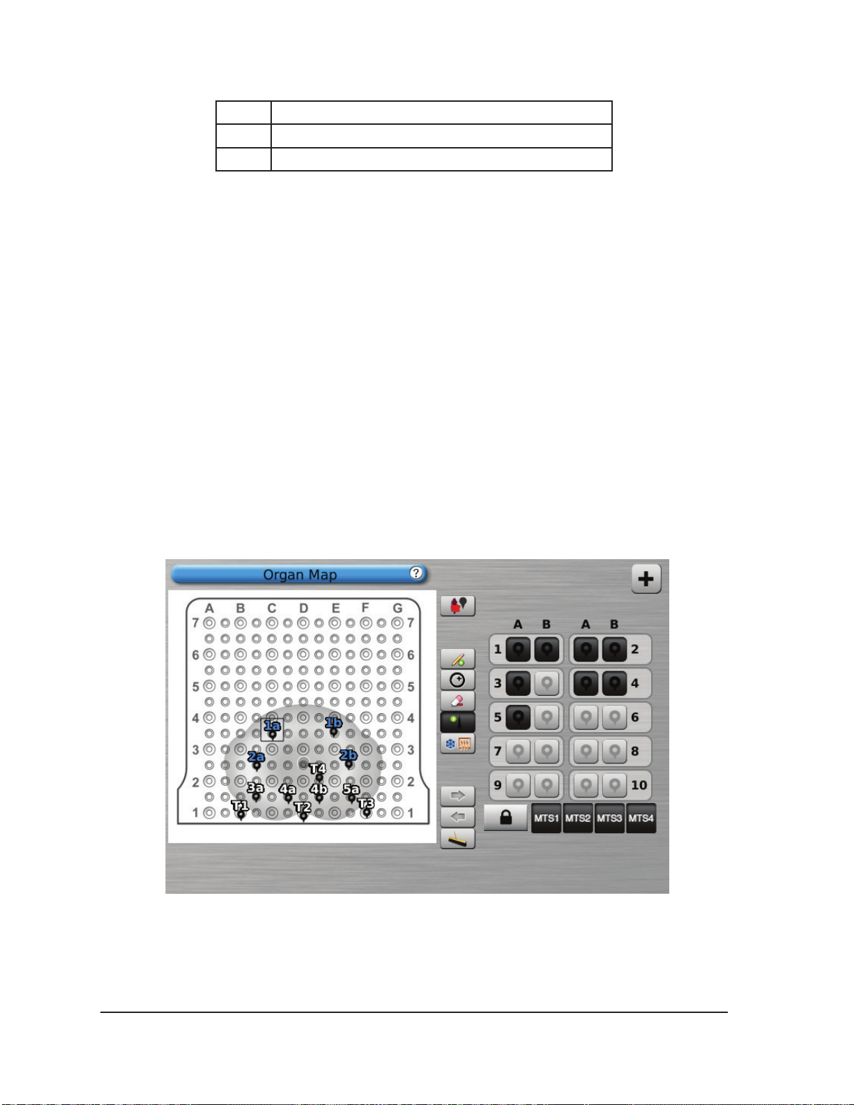
3.3.8 Organ Map
The Organ Map may be used to provide a pictorial representation of tumor location, needle placement
and cycle activity for a selected image (kidney, prostate, liver, or lung) or for a drawn image (other).
Tumor shapes may be drawn within the displayed organ, and needles placed, moved, or removed
within the organ map. A blank drawing canvas is available for customized display. Needles may be
controlled from the organ map by using the Control Needle button. Needle activity status (Freeze,
Thaw, or Idle) is represented by color coding.
Screen 3-11. Organ Map section
3-10 User Manual
Page 41
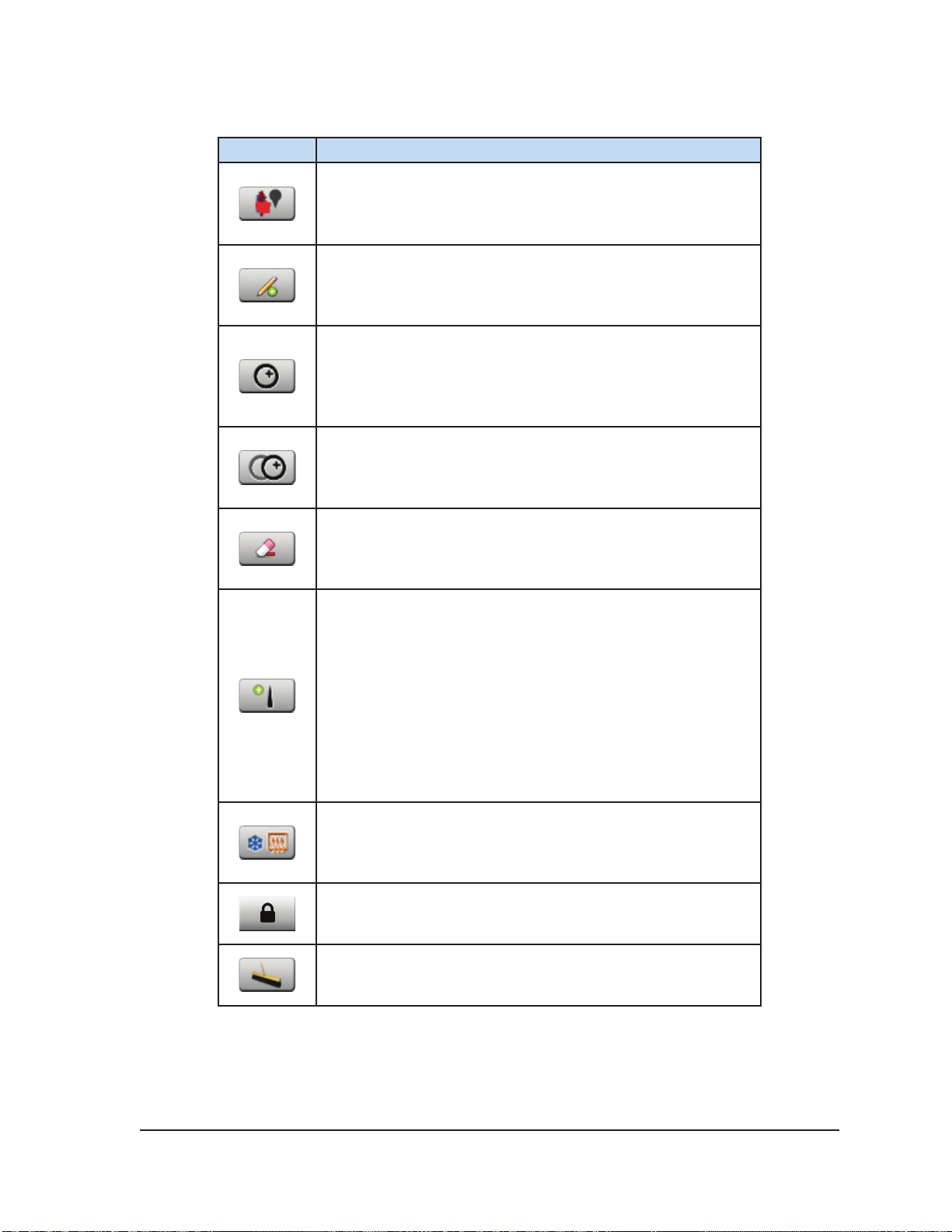
Table 3-4. Organ Map Controls
Button Description
Select Organ button – Select an organ map (kidney, prostate,
liver, lung, or other) to be displayed on the drawing area
Draw Line button – Draw free-form on the organ map or
drawing area. Line thickness and line color are selectable.
Draw Circle button – Draw a circle of various sizes on the
organ map or drawing area. Line thickness and line color are
selectable.
Move Circle button – Move a circle to another area on the
organ map. This button appears only when a circle has been
selected.
Erase button – Erase lines previously added to the drawing
space. The size of the eraser is selectable.
Place Needle button – Select and place needles and MTS
on the organ map. Needles are selectable and identied by
channel and needle port (e.g., 1a, 1b, 2a, etc.). MTS are
selectable by MTS port. Drag the needle or MTS to the desired
location on the Organ Map to place it. Place each needle on
the Organ Map as it is inserted into the target tissue to avoid
potential mix-up of needle locations.
The status of the needle(s) placed on the organ map displays
the state of the needle (Freeze, Thaw, Idle) by color coding,
matching that identied in the Channel Status section.
Control Needle button – Initiate freeze and thaw cycles of the
selected needles.
Needle Lock button – Lock a needle in place on the organ
map so that it may not be inadvertently moved.
Clear All button – Clear all drawings and needle placements
from the drawing canvas.
Visual-ICE™ Cryoablation System
3-11
Page 42
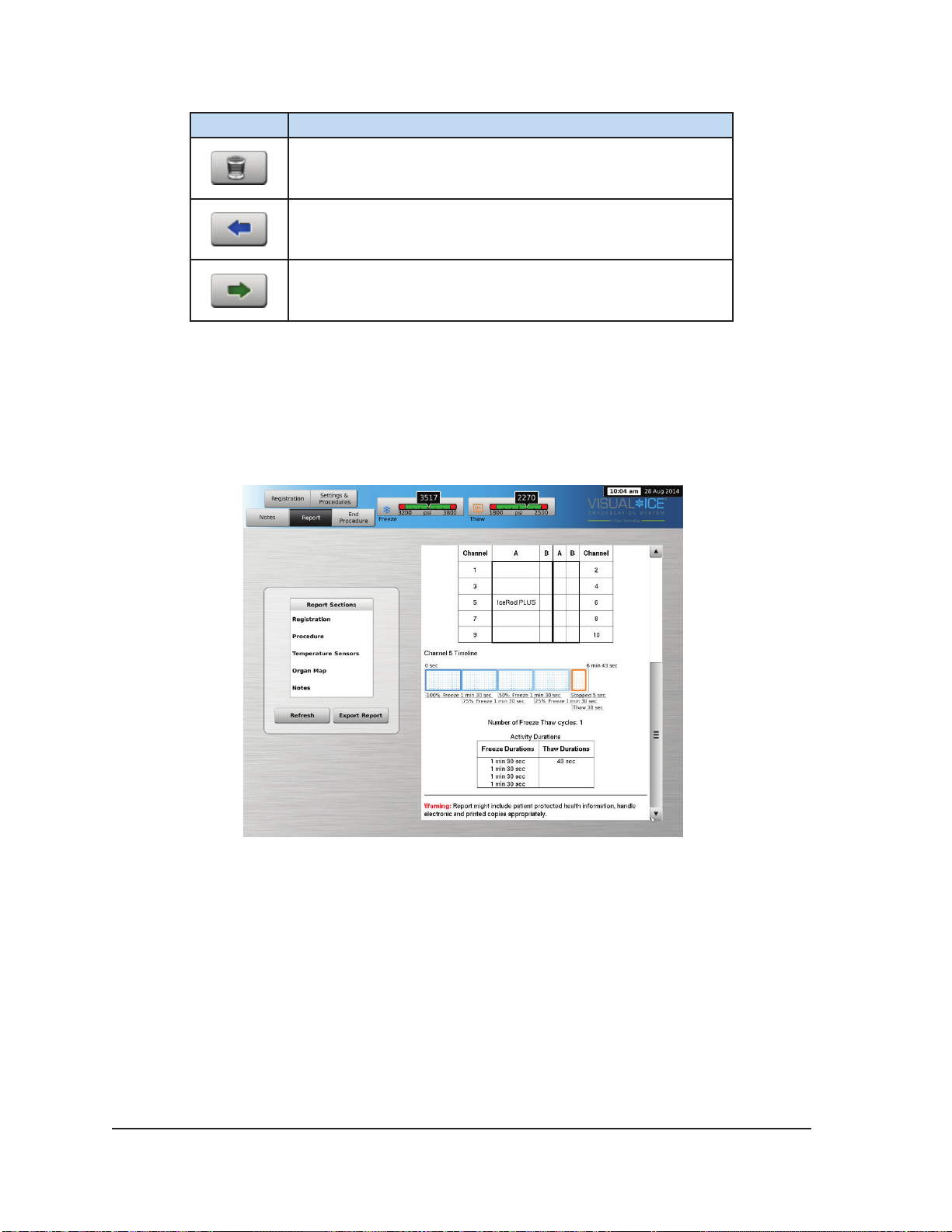
Button Description
Trash button – Delete a needle on the organ map.
Previous Image button – Change the view of the selected
organ.
Next Image button – Change the view of the selected organ.
3.4 View Reports
Procedure reports provide a summary of a cryoablation procedure. The reports contain the
information provided in the Registration screen, details of the freeze-thaw cycles, number of MTS
needles, graphical history of freeze, thaw, and cautery phases, graphical history of MTS readings,
organ map used with needle placement identication, and any notes entered by the physician.
Screen 3-12. Procedure Report Example
To view a report that has been saved to the Visual-ICE System, press the View Reports button from
the Startup Screen (Screen 3-2).
The View Reports Screen displays a list of all saved procedure reports in the Visual-ICE System
(Screen 3-13). You may select a report to be viewed or exported, or you may delete your own reports.
Users with an administrative login ID may delete any report.
3-12 User Manual
Page 43
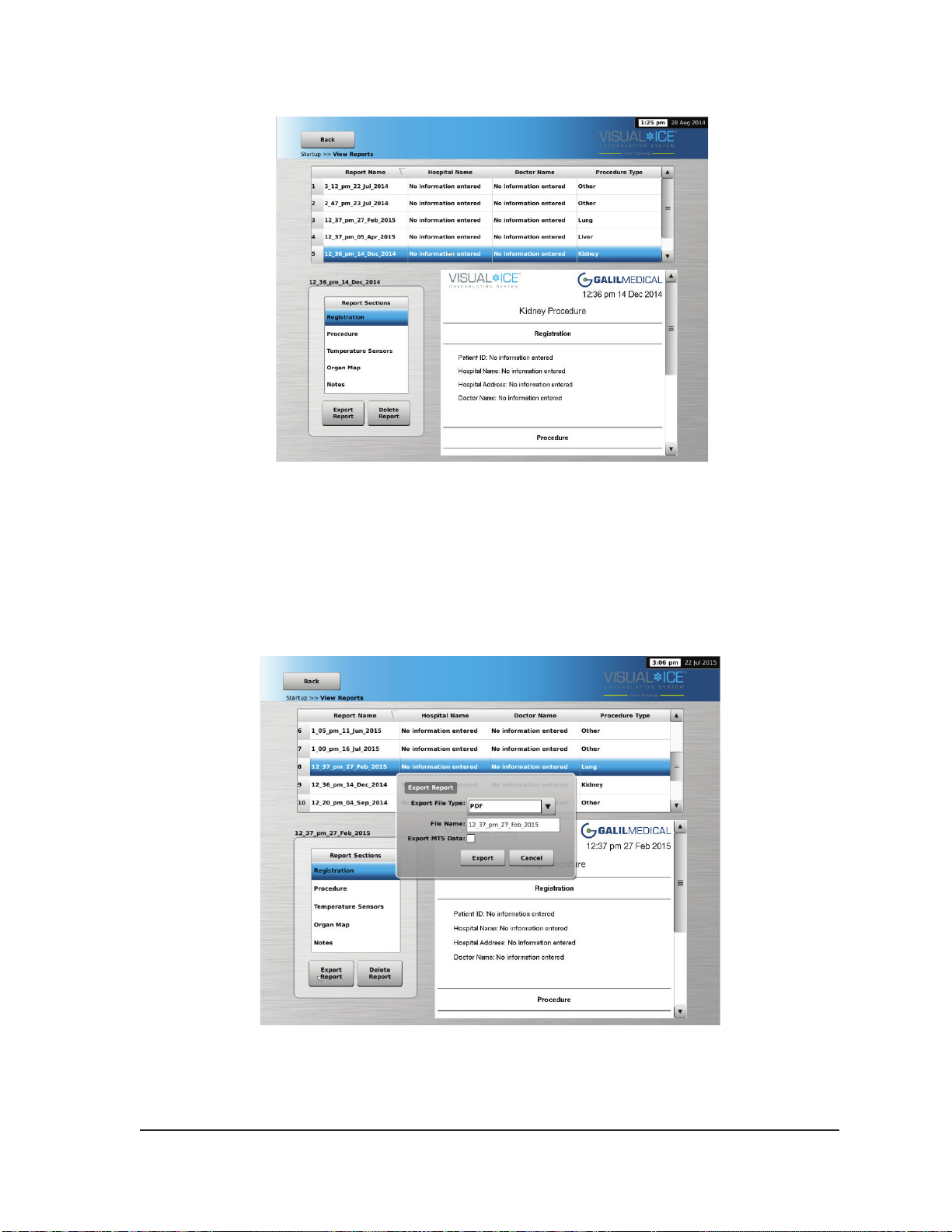
Screen 3-13. View Reports Screen
To sort the list by Report Name, Hospital Name, Physician Name, or Procedure Type, press the
appropriate header section of the report list.
The Export Report button displays a window to choose the Export File Type and File Name for
exporting the report. Reports can be exported in HTML, PDF, or CSV formats. An additional option is
available to export raw MTS data for further analysis.
Screen 3-14. Export Report Screen
Visual-ICE™ Cryoablation System
3-13
Page 44
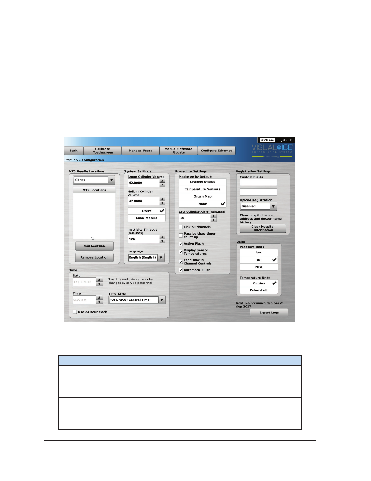
3.5 Congure Settings
The Congure Settings Screen allows selection of settings used during a cryoablation procedure.
Settings that may be changed include MTS Needle Locations, System, Procedure and Registration
Settings and Units (reference Section 5.1).
Control buttons have options for Calibrate Touch Screen, Manage Users, Manual Software Update,
and Congure Ethernet (reference Section 5.1). The Manual Software Update and the Congure
Ethernet buttons are available only to system administrators and service personnel.
Only Service personnel have the option to adjust the system time and date.
Screen 3-15. Congure Settings
Table 3-5. Congure Settings Options
Button
Calibrate
Touchscreen
Manage Users
3-14 User Manual
Function
Calibrate the touchscreen.
Change your password.
Administrative users may add users, remove users, or change the
password of any user.
Page 45
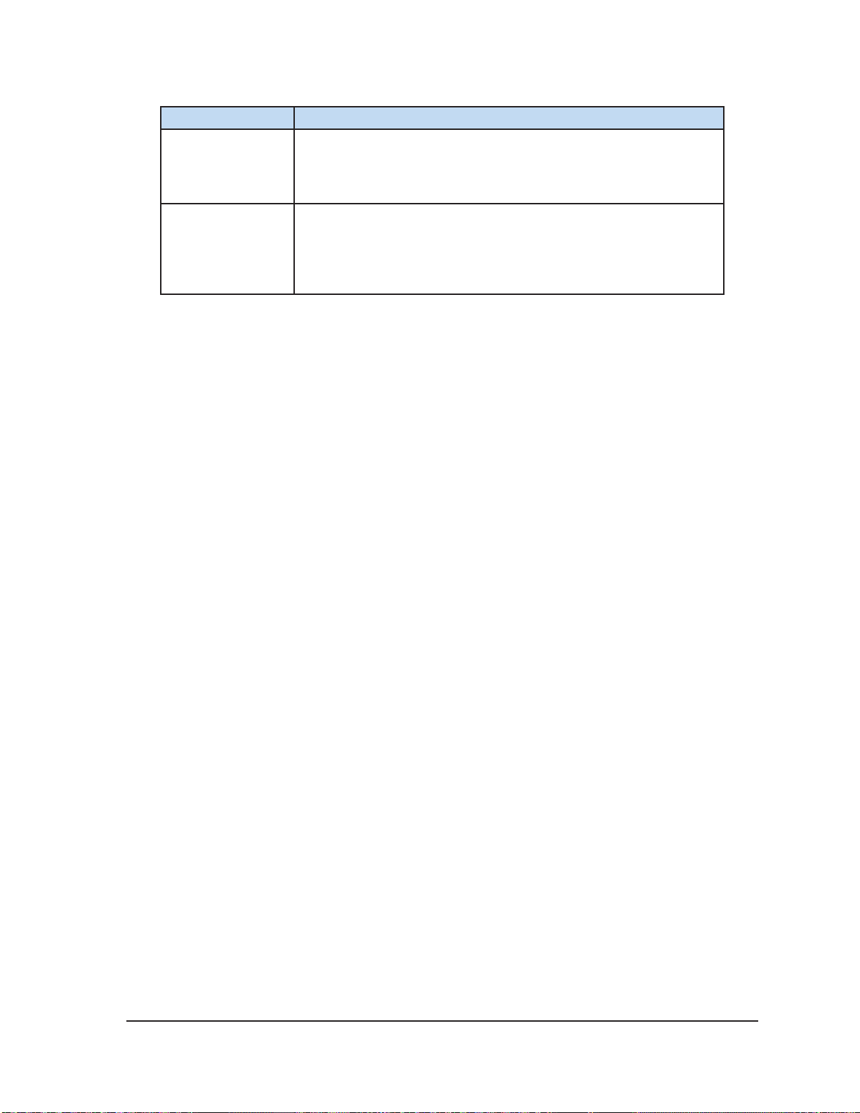
Button
Manual Software
Update
Congure
Ethernet
Function
Install a software update via a USB ash drive.
NOTE: This function is available only to administrative and service
users.
Congure the Ethernet connection for remote uploading of reports
or downloading of software versions.
NOTE: This function is available only to administrative and service
users.
3.6 Service Screen
The Service Screen is available only to Galil Medical trained, authorized service personnel with
a service login ID. The Service Screen provides service users with the ability to run system
diagnostics, enable or disable system features, adjust minimum and maximum gas pressures, view
event logs, and perform manual system conguration.
3.7 Remote Upload / Download
While the system is OFF, connect the Ethernet cable between the Ethernet port in the monitor storage
compartment and an Ethernet wall socket in the facility. Power the system ON and login.
Select the Remote Upload / Download screen to connect to a Galil Medical server for remote
uploading of procedure reports or downloading of system software versions. The Visual-ICE
Cryoablation System automatically checks for connectivity to the Galil Medical server. Select the
appropriate box for either uploading reports or downloading updates and press Start (Screen
3-16). A conrmation message appears when the upload / download process has been successfully
completed (Screen 3-17).
Restart the Visual-ICE System following successful completion of a software update download to
begin using the new software version. The current software version number is displayed in the upper
right hand corner of the Startup Screen (Screen 3-2).
When Remote Upload / Download is used to upload procedure reports to the Galil server, the data
are encrypted to protect the privacy of patient health information.
Visual-ICE™ Cryoablation System
3-15
Page 46
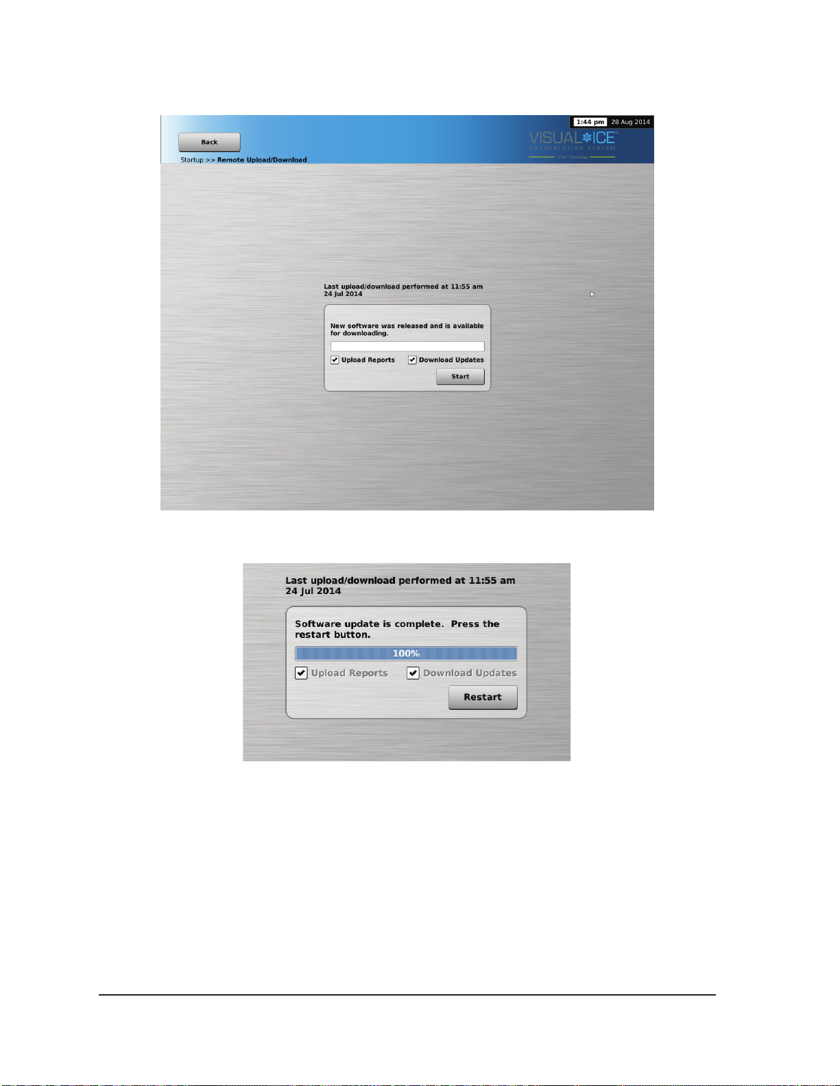
Screen 3-16. Remote Upload / Download Screen
Screen 3-17. Successful Upload / Download
3-16 User Manual
Page 47

4 SYSTEM OPERATION
Table 4-1 depicts the order and steps of the Visual-ICE™ Cryoablation System set-up and treatment
procedure. Each step is described in detail in this chapter.
Table 4-1. Cryoablation Procedure Flow
• Conrm availability of gas, needles, and accessories
• Position Visual-ICE System and lock brake
Set-up Console
1.
2.
Connect Gas
Cylinders
Needle / MTS
3.
Testing
• Ensure Manual Vent Valve is closed and Argon
Shuto Valve is ON
• Power Visual-ICE System ON
• Login
• Connect helium gas, if applicable
• Connect argon gas
• Ensure safety cables are connected
• OPEN valve on helium, then argon
• Enter patient treatment information in Registration
Button
• Prepare sterile needles for testing
• Connect needles to Visual-ICE System and lock
channels
• Perform Needle Integrity and Functionality Test
• Test Multi-Point Thermal Sensors, if applicable
• Insert needles into target tissue
• Deliver the cryoablation treatment and remove
needles
• View and save reports, if desired
• Depressurize the system and shutdown
4.
Conduct
Cryoablation
Procedure
4.1 Preparation for Use
Prior to using the Visual-ICE System, inspect the chassis, power cord, brake, safety cables, gas
supply lines, gas connections, and the monitor touch screen to ensure they are not damaged. If any
of the components are damaged, contact Galil Medical Customer Service.
CAUTION. If condensation is present on the system, allow the system to dry completely for 12
hours prior to powering up the system. Powering up the system with condensation could result in
permanent damage to the electrical boards, causing the system to be inoperable.
Before the patient is anesthetized, set up the Visual-ICE System, connect the gas cylinders, and
conduct functionality tests on each cryoablation needle and thermal sensor (reference Section 4.1.4).
Visual-ICE™ Cryoablation System
4-1
Page 48

4.1.1 System Set-up
1. Position the Visual-ICE System alongside the patient table. Ensure that the needle gas tubing
has sucient length to reach the patient. Ensure that the power switch and the power control
knob (Figure 2-1 and Figure 2-2) are both easily accessible.
2. Lock the two front wheels using the Brake Pedal on the Visual-ICE System. If necessary, lock the
two rear wheels using the individual brakes on each wheel.
3. Plug the power cord into a hospital grade power outlet (electrical mains outlet) with a ground
connection. Galil Medical recommends using a stable and uninterruptable power outlet.
NOTE: If the power supply to the Visual-ICE System is not stable or is noisy, the MTS
temperature readings may be inaccurate.
WARNING. To avoid risk of electric shock, this equipment must only be connected to a
hospital grade electrical power outlet with a protective earth.
WARNING. Do not touch the chassis of the Visual-ICE Cryoablation System while
touching the patient to avoid the potential risk of shocking the patient if an inadvertent
electrical fault exists.
OPTIONAL: When performing a prostate cryoablation procedure, set up a urethral warmer
system by following directions provided in the Urethral Warming Set Instructions for Use.
4. Ensure that the power switch located on the rear of the system is in the ON position (Figure 2-2).
This power switch should remain ON at all times. The Visual-ICE System will not turn ON if this
power switch is in the OFF position.
5. Conrm that the Argon Shuto Valve on the Visual-ICE System is in the GAS ON position. Turn it
to the GAS ON position, if needed.
6. Conrm the Manual Vent Valve is fully closed (Figure 2-2). If needed, turn the knob clockwise
until it is fully closed.
7. Raise the monitor to the UP position and adjust it to a comfortable viewing angle.
CAUTION. Use care when swiveling the touch screen monitor to avoid the potential for pinching
ngers.
8. Turn the system ON using the power control knob located near the Needle Connection Panel
(Figure 2-4).
During boot-up, the system performs several diagnostic tests to verify that the hardware and
software are operating properly. The system may produce a series of clicking sounds when the
system performs self-diagnostic tests. This boot-up process is completed in approximately 45
seconds.
NOTE: If the system was improperly shutdown after the previous procedure, the boot-up process
could take up to 2 minutes.
NOTE: It is important to power up the system prior to connecting the gas to the system. If the
system is not powered up prior to connecting the gas, the diagnostic tests will not be performed
by the software.
4-2 User Manual
Page 49
The diagnostic tests check:
• The correct version of rmware is running on the system
• Critical system components including the solenoid valves, internal power supplies, cooling
fans, pressure transducers, and temperature measuring circuits.
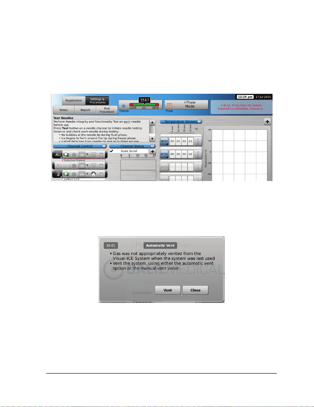
If the system detects a failure of an individual channel, the channel is disabled and the needle
type display window, bordered in red, notes the channel is defective. A message indicating the
failure is displayed in the upper right-hand corner of the Navigation Tool Bar.
Screen 4-1. Disabled Channel
A failure that prevents use of the system displays a message directing you to contact Galil
Medical Customer Service (reference Section 7.7).
If the Visual-ICE System software detects pressurized gas in the system and the gas supply is
not connected, a message appears requesting you to vent the gas from the system.
Screen 4-2. Vent Gas Message
Visual-ICE™ Cryoablation System
4-3
Page 50
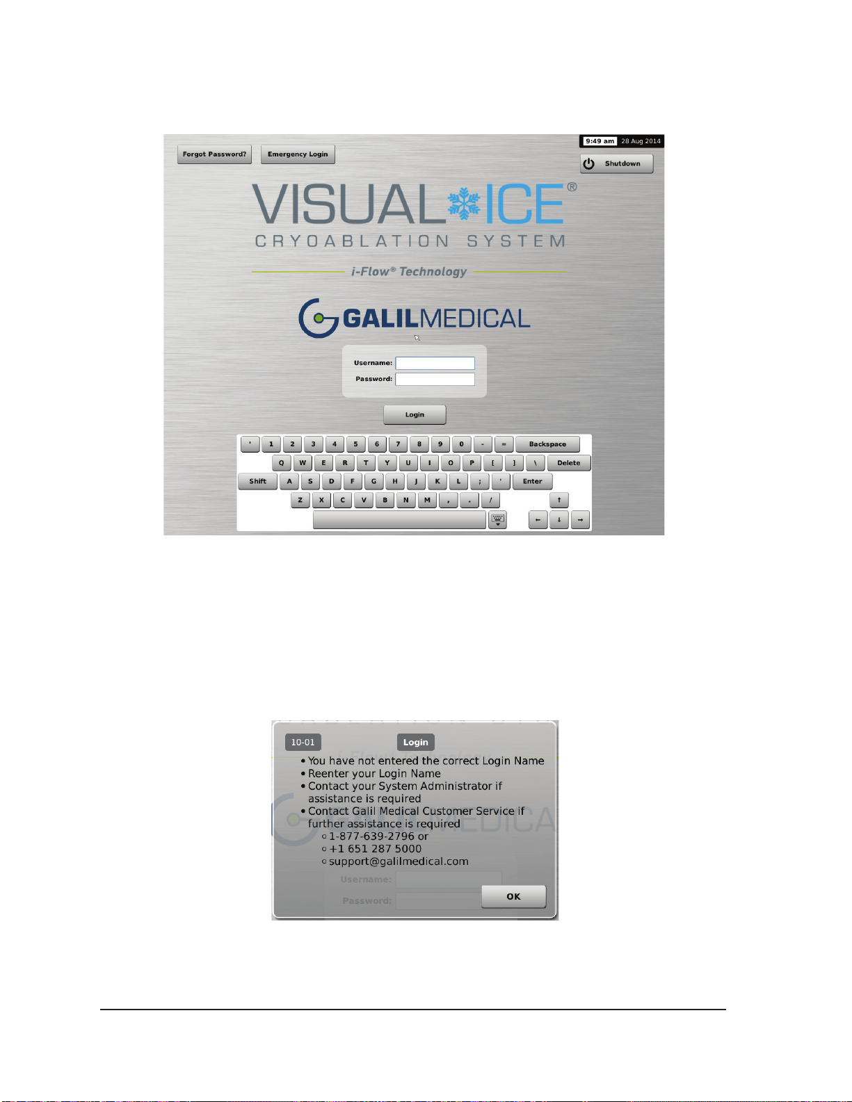
The Login Screen appears after the boot-up process is complete.
Screen 4-3. Login Screen
9. Enter your assigned login name and password using the on-screen virtual keyboard.
NOTE: The login name and password are not case-sensitive. Numbers are displayed when the
keyboard is in upper case. To change text case, use the shift button on the virtual keyboard.
NOTE: If you leave the user interface idle for a pre-set time with no activity, the Visual-ICE
System software requires you to re-enter your password to unlock the user interface (reference
Section 5.1).
Screen 4-4. Incorrect Login
4-4 User Manual
Page 51
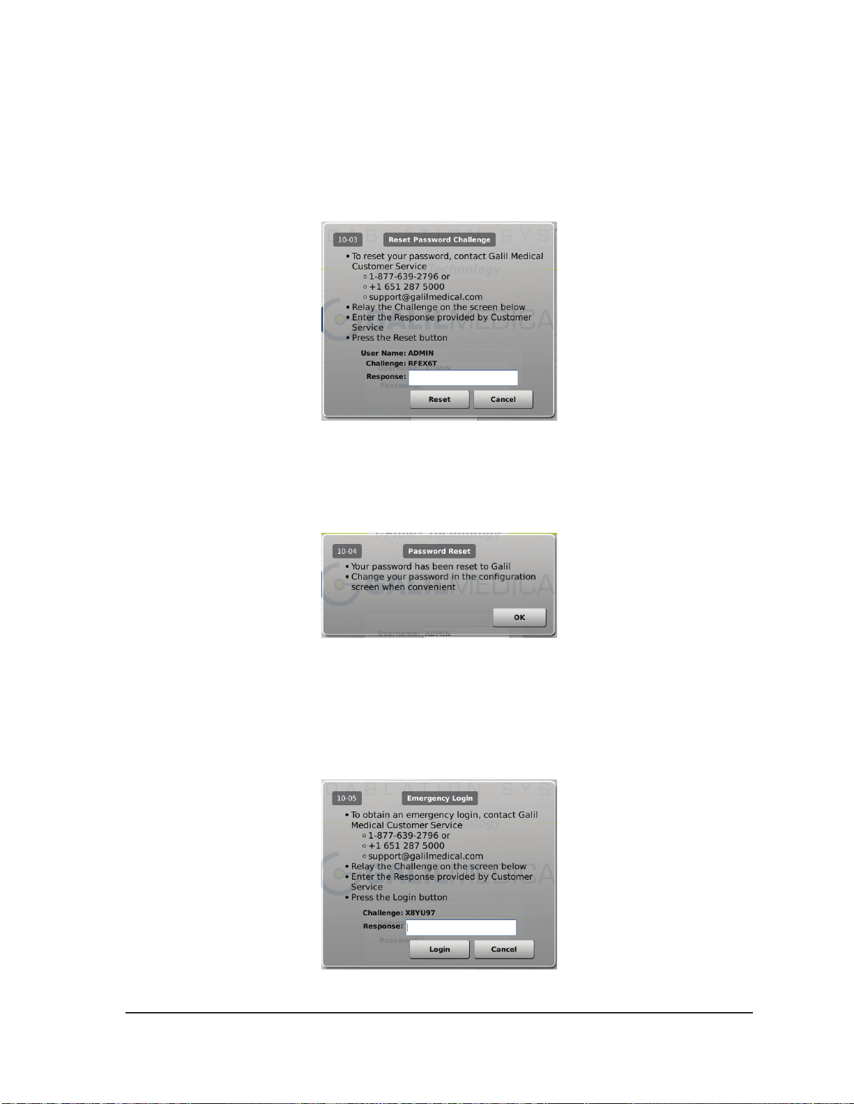
Additional Login Options:
If you forgot your password, contact your System Administrator and request that the administrator log
in, go to the Manage Users screen and change your password.
Alternatively, press the Forgot Password button at the top of the screen (Screen 4-3). A displayed
message provides a challenge to be relayed to Galil Medical Customer Service (Screen 4-5).
Screen 4-5. Reset Password Challenge
Customer Service will provide a response to be entered on the screen using the virtual keyboard.
Your password will be reset (Screen 4-6) and you will have an opportunity to change your password
in the conguration screen.
Screen 4-6. Password Reset
In case of emergency, press the Emergency Login button at the top of the screen (Screen 4-3). A
message is displayed with a challenge. Call Galil Medical Customer Service to receive the proper
response to enter, then press the Login button (Screen 4-7).
NOTE: This action does not reset your password.
Screen 4-7. Emergency Login
Visual-ICE™ Cryoablation System
4-5
Page 52
After successful login, the Startup Screen appears (Screen 3-2).
4.1.2 Connecting Gas Cylinders
WARNING. Do not connect the Visual-ICE Cryoablation System to a gas supply exceeding
6000 psi (414 bar, 41.4 MPa) to avoid damage to internal system components.
WARNING. Ensure that the gas cylinders are chained to a wall or an approved cart to prevent
inadvertent tipping of the cylinders.
CAUTION. Galil Medical recommends having additional backup argon cylinders available for each
treatment.
CAUTION. Turn the Visual-ICE Cryoablation System ON before connecting the gas cylinders to
ensure the proper diagnostic tests are conducted.
NOTE: If cryoablation needles with i-Thaw technology are being used, only argon gas is required
to be connected. If helium gas is connected, i-Thaw technology is disabled and only thawing with
helium gas is available.
1. Position the gas cylinder(s) close enough to the Visual-ICE System to ensure that the gas supply
line is not stretched and does not present a trip hazard.
2. On the rear of the Visual-ICE System, ensure that the Manual Vent Valve is in the CLOSED
position.
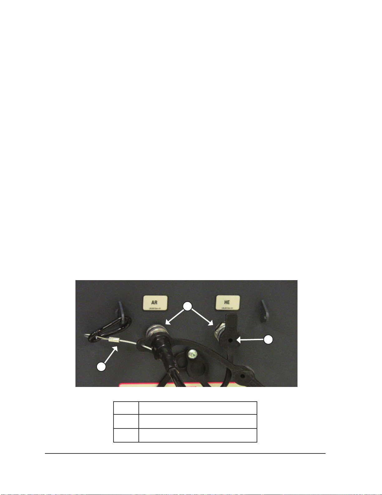
3. Remove the humidity covers from the helium and argon inlets on the Visual-ICE System.
4. Secure the safety cable at the end of the gas supply line to the system.
WARNING. Ensure that the safety cable is properly secured to the system in case the gas
supply line becomes accidentally disconnected.
5. Connect the helium high-pressure gas supply line to the helium inlet of the Visual-ICE System
using the quick-connect connector located at the rear of the system.
2
3
1
Figure 4-1. Visual-ICE System Gas Connections
1 Safety cable
2 Quick-connect connectors
3 Humidity cover
4-6 User Manual
Page 53
6. Route the helium gas supply line through the supply line clip on the Console.
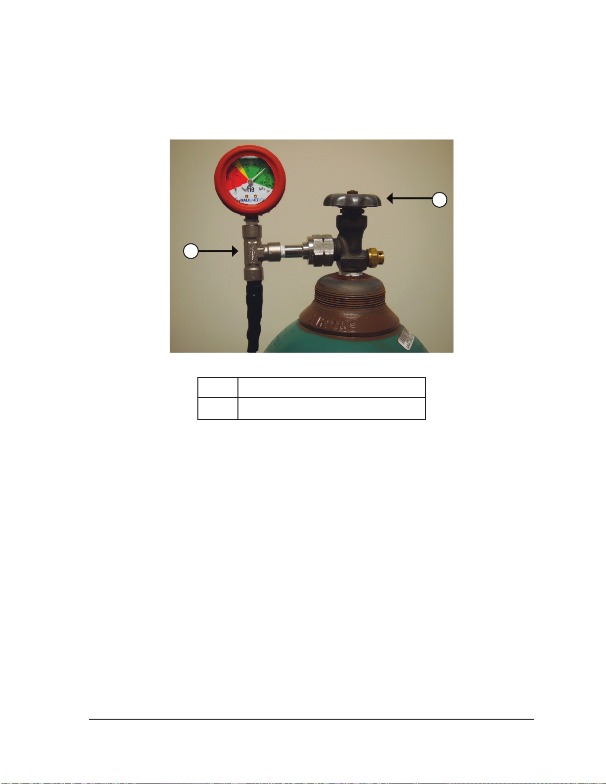
7. Connect the helium high-pressure gas supply line to the helium cylinder by securing the gauge
assembly adapter onto the cylinder connection (Figure 4-2).
NOTE: Gas cylinder connections have left-handed threads.
2
1
Figure 4-2. Gas Cylinder Set-up
1 Gauge assembly adapter
2 Cylinder valve
8. Carefully turn the cylinder valve on the helium gas cylinder counter-clockwise for one quarter
turn. Ensure that the pressure reading on the gauge responds immediately. Turn the cylinder
valve further counter-clockwise (approximately one full turn) to fully open the gas cylinder so that
sucient gas ow is present.
9. Repeat the procedure outlined in Steps 4 through 8 to connect the argon gas cylinder to the
Visual-ICE System, using the argon gas supply line.
If no argon pressure is displayed on the system pressure gauge, ensure the Argon Shuto Valve
is in the GAS ON position.
OPTIONAL:
• The EZ-Connect2 Dual Cylinder Adapter connects two cylinders of argon gas to the
Visual-ICE System to support a cryoablation procedure. A four-way adapter assembly with
argon pressure gauge connects a gas supply line, the primary gas cylinder, and an auxiliary
gas supply line.
• If using the optional EZ-Connect2 Adapter, connect the gas supply line with four-way
pressure gauge adapter assembly to the primary argon cylinder by securing the gauge
assembly adapter onto the cylinder connection.
• Connect the end of the gas supply line to the argon inlet of the Visual-ICE System using the
quick-connect connector.
Visual-ICE™ Cryoablation System
4-7
Page 54
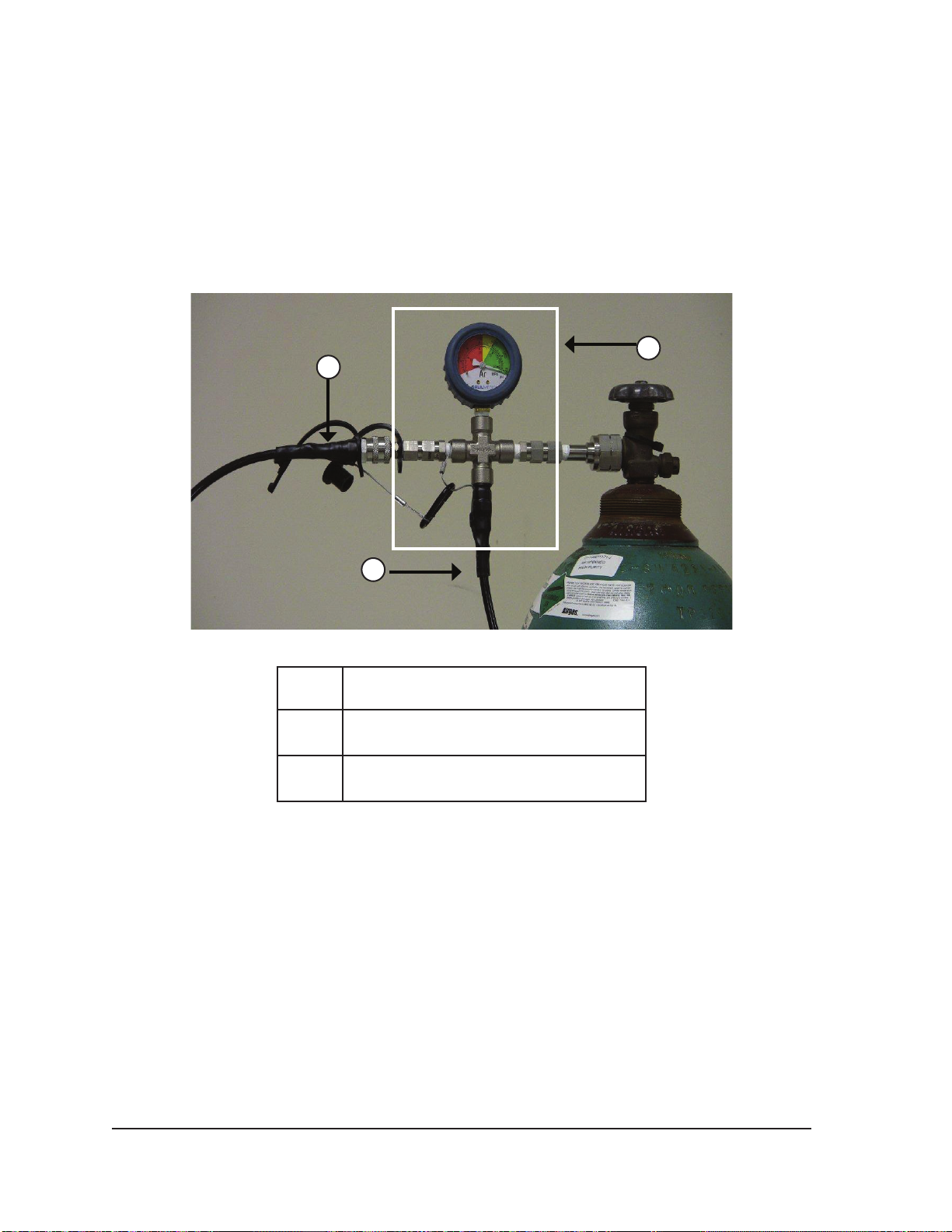
• Connect the auxiliary gas supply line to the four-way adapter assembly using the quick-
connect connector located on the end of the auxiliary gas supply line.
• Connect the opposite end of the auxiliary gas supply line to the second argon cylinder by
securing the end of the auxiliary line to the cylinder connection.
• Open the primary cylinder valve rst and use this cylinder until depleted. Do not open the
cylinder valve on the second cylinder until the initial cylinder has been depleted.
• Reference Section 4.5 for instructions on changing the gas cylinder during a procedure, if the
second cylinder is also depleted during the procedure.
2
1
3
Figure 4-3. EZ-Connect2 Dual Cylinder Adapter
1 Auxiliary Gas Supply Line
Four-way Adapter Assembly with
2
Pressure Gauge
3 Gas Supply Line
CAUTION. Before beginning the cryoablation procedure, ensure availability of sucient gas to
conduct the planned cryoablation procedure (reference Section 8.5 for gas purity requirements).
10. Ensure the Gas Indicator (Screen 3-4) displays the minimum working pressure before initiating a
procedure (Table 4-2). The Gas Indicator should indicate the pressure to be in the green range.
If the system detects that the pressure reading for either gas cylinder is less than 50 psi, a
message displays on the Navigation Tool Bar (Screen 4-8). Connect the gas cylinders to the
Visual-ICE System.
4-8 User Manual
Page 55
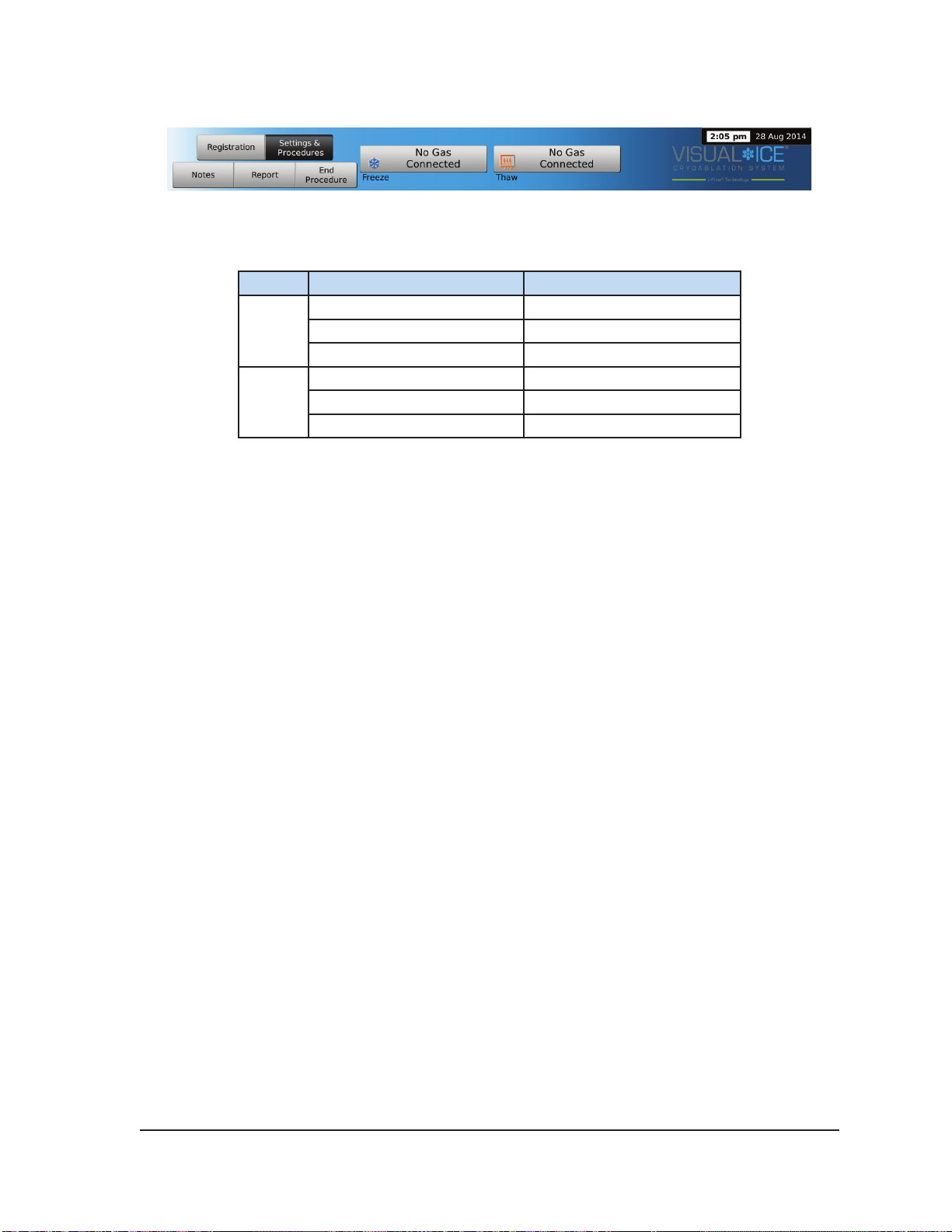
Screen 4-8. No Gas Connected message
Table 4-2. Working Gas Pressures
Gas Nominal Working Pressure Working Pressure Limits
3500 psi 3200 – 3800 psi
Argon
Helium
NOTE: When helium is not connected, active thawing can be conducted with an i-Thaw-capable
cryoablation needle. The system will ow argon gas at 500 psi (34 bar, 3.4 MPa) through the needle
and will energize the internal heating element of the i-Thaw-capable needle when the Thaw button is
pressed.
CAUTION.
• When the gas cylinder pressure falls below the lower working pressure limit, the system
displays an alert message in the Navigation Tool Bar. To ensure optimal performance,
replace a gas cylinder if the pressure falls below the lower working pressure limit.
• Failure to operate the Visual-ICE System within the working pressure limits may aect the
cryoablation procedure.
• If the system produces a continuous hissing sound, verify that the Manual Vent Valve is fully
closed. If the Manual Vent Valve is fully closed and the hissing sounds persists, shut OFF the
system using the power control knob located on the front of the system (Figure 2-1). Close
the gas supplies using the cylinder valves. Contact Galil Medical Customer Service.
241 bar 221 – 262 bar
24.1 MPa 22.1 – 26.2 MPa
2200 psi 1800 – 2500 psi
152 bar 124 – 172 bar
15.2 MPa 12.4 – 17.2 MPa
4.1.3 Gas Line Flushing
After argon is connected and the gas lines pressurized, the Visual-ICE System automatically
conducts gas line ushing to reduce potential gas line contaminants.
• When argon is connected to the system and the gas lines pressurized prior to pressing Start
Procedure, the automated ushing will occur before the Procedure Screen is displayed.
• When the Procedure Screen is displayed before the argon is connected, automated ushing
will occur after the connected gas pressurizes the lines.
During the ushing procedure, a sequence of gas ow, followed by an idle period, will occur three
times.
• Gas will ow for 3 seconds.
• An idle period of 30 seconds will follow the gas ow.
• The automated ushing process will be completed in ~ 90 seconds.
As the system conducts gas line ushing, the screen displays Optimizing Lines.
Visual-ICE™ Cryoablation System
4-9
Page 56
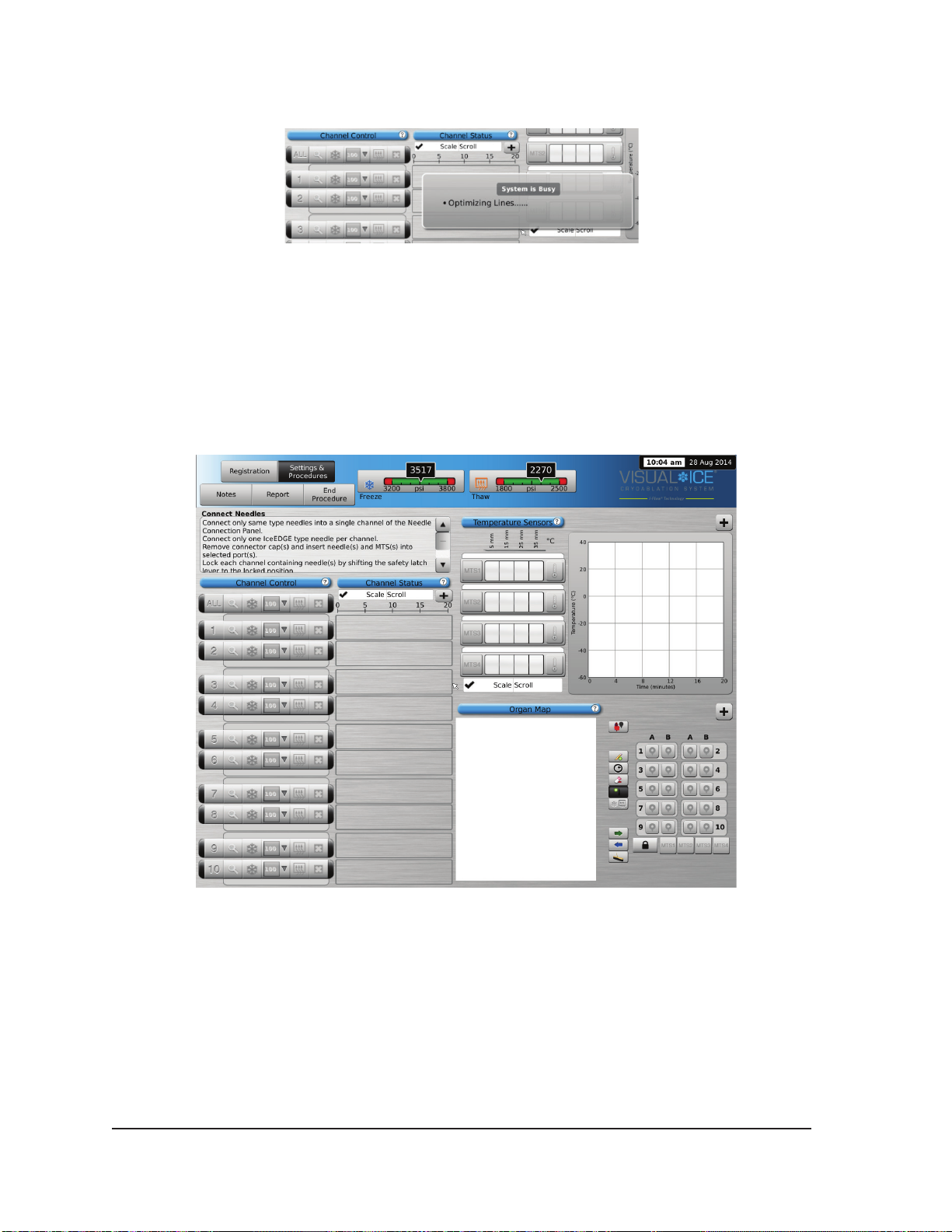
Screen 4-9. Optimizing Lines message
4.1.4 Pre-Procedure Testing
WARNING. Prior to beginning a treatment and before the patient is anesthetized, set up the
Visual-ICE System and perform functionality tests on each cryoablation needle and thermal
sensor.
1. On the touch screen monitor, press Start Procedure. The Procedure Screen appears (Screen
4-10).
Screen 4-10. Procedure Screen
2. Using aseptic technique, carefully remove the cryoablation needle from the package and place in
a sterile work area.
3. Remove the connector cap, and then connect the needle to the Visual-ICE System needle
connection panel (Figure 2-4).
CAUTION. Do not kink, pinch, cut or pull excessively on the needle tubing. Damage to needle handle
or tubing may cause the needle to become unusable.
4-10 User Manual
Page 57
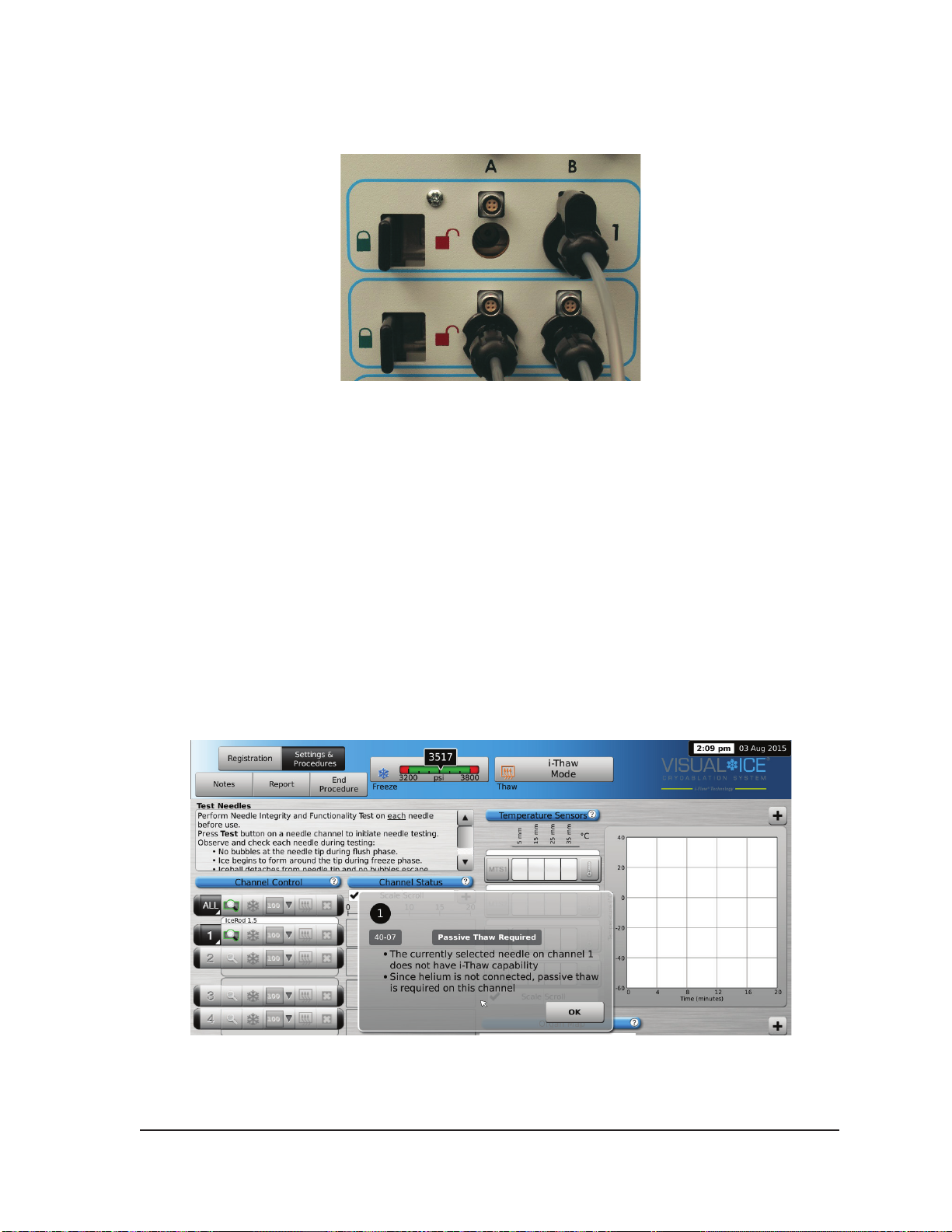
4. After a needle(s) is inserted into the desired channel, lock the channel by sliding the locking bar
away from the center of the system (Figure 4-4).
Figure 4-4. Locking Needle into Channel
5. To allow for easier identication of the needle when multiple cryoablation needles are used during
a cryoablation procedure, it is recommended to place a label on the needle tubing.
NOTE: Contact Galil Medical Customer Service to order labels for the cryoablation needles.
6. Repeat Steps 2 through 5 for each cryoablation needle that will be tested.
CAUTION. Galil Medical recommends that only needles of the same type be placed together in a
single channel. Do not combine i-Thaw capable needles with non-i-Thaw capable needles in the
same channel. Additionally, using needles of diering types in a channel may aect the accuracy of
the Gas Indicator.
CAUTION. If the Visual-ICE System detects that helium gas is connected, the system defaults to
helium thaw mode and i-Thaw, FastThaw, and Cautery capabilities are disabled.
NOTE: The Visual-ICE System displays a message if one or more needles without i-Thaw technology
are connected and helium gas is not connected to the system. Ensure helium gas is connected to the
system to use active thaw without i-Thaw.
Screen 4-11. Thawing Mode message
Visual-ICE™ Cryoablation System
4-11
Page 58
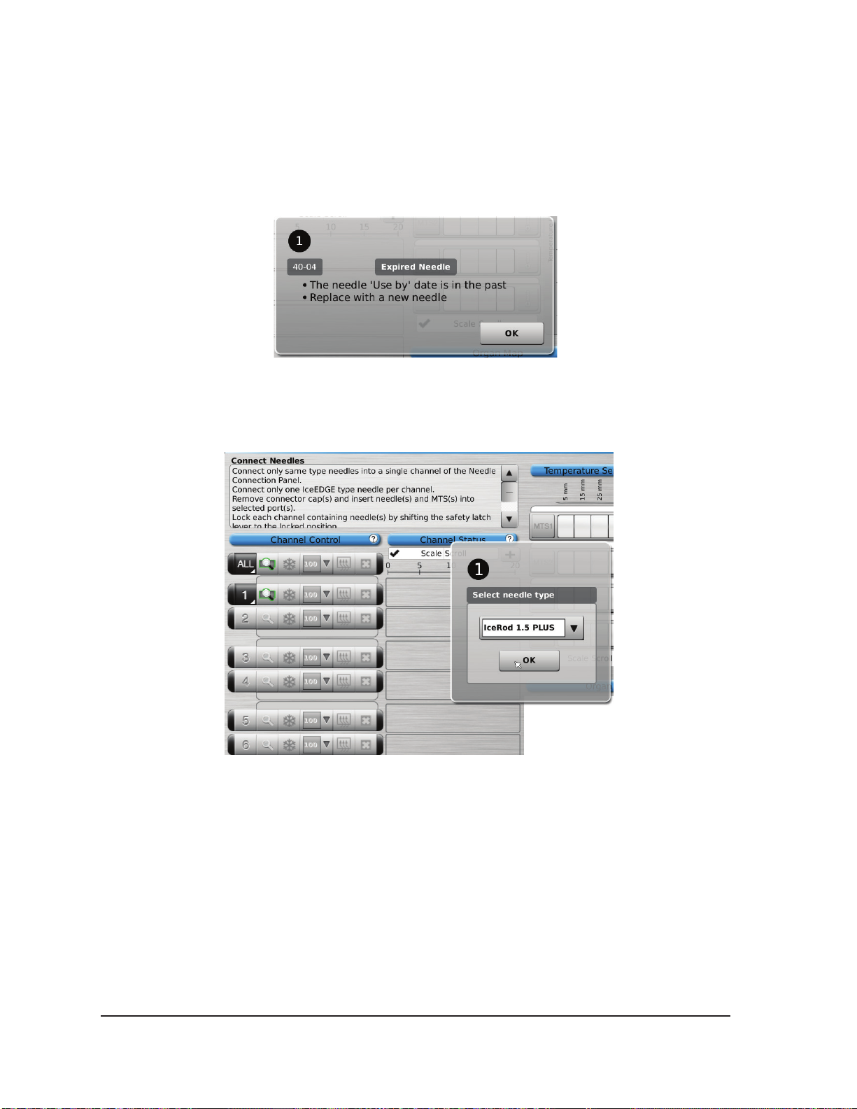
When the channel has been locked, the software detects that a needle has been connected
and the channel opens for testing. A dark gray channel button indicates a channel with needles
connected. If the needle contains a memory chip, the Visual-ICE System automatically detects
the type of needle being used, the lot number, and the expiration date of the product. If the
system detects that the expiration date has passed, a message appears and gas ow to that
channel is disabled.
Screen 4-12. Needle Past Expiration Date message
7. If the needle does not contain a memory chip, a menu appears with a selection of needle types
(Screen 4-13). Select the proper needle type from the drop-down menu.
Screen 4-13. Select Needle Type Menu
8. After selecting the rst needle, the selection for subsequent needles defaults to the initial
selection. Conrm needle type displayed in each channel matches the needle type connected.
9. Press and hold the Channel button to open Advanced Channel Controls, which allows you to
change the needle type for a channel, as needed.
10. Prepare to conduct Needle Integrity and Functionality Testing.
CAUTION. Take care to maintain sterility of each needle during testing.
• Secure the needle tubing to the sterile table prior to beginning the needle testing process.
• Fill a large basin (at least 30 cm in diameter) halfway with sterile water or saline.
• Place the needles, individually or in groups, in the basin such that the full length of the needle
shaft is submerged in the sterile water or saline.
4-12 User Manual
Page 59

11. Perform the Needle Integrity and Functionality Test on each needle by pressing the Test button
on the channel containing the needle(s). The 90-second test automatically conducts a series of
ush, freeze, and thaw phases. The durations of these phases are: 45 seconds ush with helium,
15 seconds freeze with argon, and 30 seconds thaw with helium.
OPTIONAL: Alternatively, all needles may be tested simultaneously by pressing the Test button
on the channel labeled ALL. A message requests conrmation to test all needles. If appropriate,
choose YES.
OPTIONAL: If additional testing is required, press the Test button again to repeat the test.
NOTE: When helium is not connected, the two-minute test consists of 50 seconds low-pressure
argon ow, 15 seconds freeze with high-pressure argon, and 55 seconds of low-pressure argon
ow.
NOTE: If a previously tested needle is moved to a new channel at any time during a procedure,
the Needle Integrity and Functionality Test must be conducted again on that needle.
NOTE: If a previously tested needle containing a memory chip is moved to a new channel during
a procedure, the Visual-ICE System will recognize the needle has successfully completed the
Needle Integrity and Functionality Test.
During testing, carefully watch each needle for the following:
Flush: Ensure no bubbles are formed along the needle shaft and tip.
Ensure that no iceball is formed during the Flush phase.
WARNING. A defective cryoablation needle that has a gas
leak can cause a gas embolism in the patient. Never use
a defective needle for a cryoablation procedure. Return
defective needles to Galil Medical for evaluation.
CAUTION. Ice formation during the Flush phase indicates
that argon gas is connected to the helium inlet. Before
proceeding change the cylinders and ensure that each gas
supply line is connected to the correct cylinder (reference
Section 4.5.1).
Freeze: Ensure that ice begins to form around the tip of the needle.
WARNING. A needle is defective if there is no ice
formation during the Freeze phase. Do not use a
defective needle. Obtain a new needle and repeat the
testing procedure.
Thaw: CAUTION. Ice formation during the Thaw phase indicates
that the argon gas is connected to the helium inlet. Before
proceeding change the cylinders and ensure that each
cylinder is connected to the correct inlet (reference Section
4.5.1).
Upon successful completion of the Needle Integrity and Functionality Test, the Test button
displays a green check and remaining control buttons on the channel become active. The
needle(s) are ready for use.
Visual-ICE™ Cryoablation System
4-13
Page 60
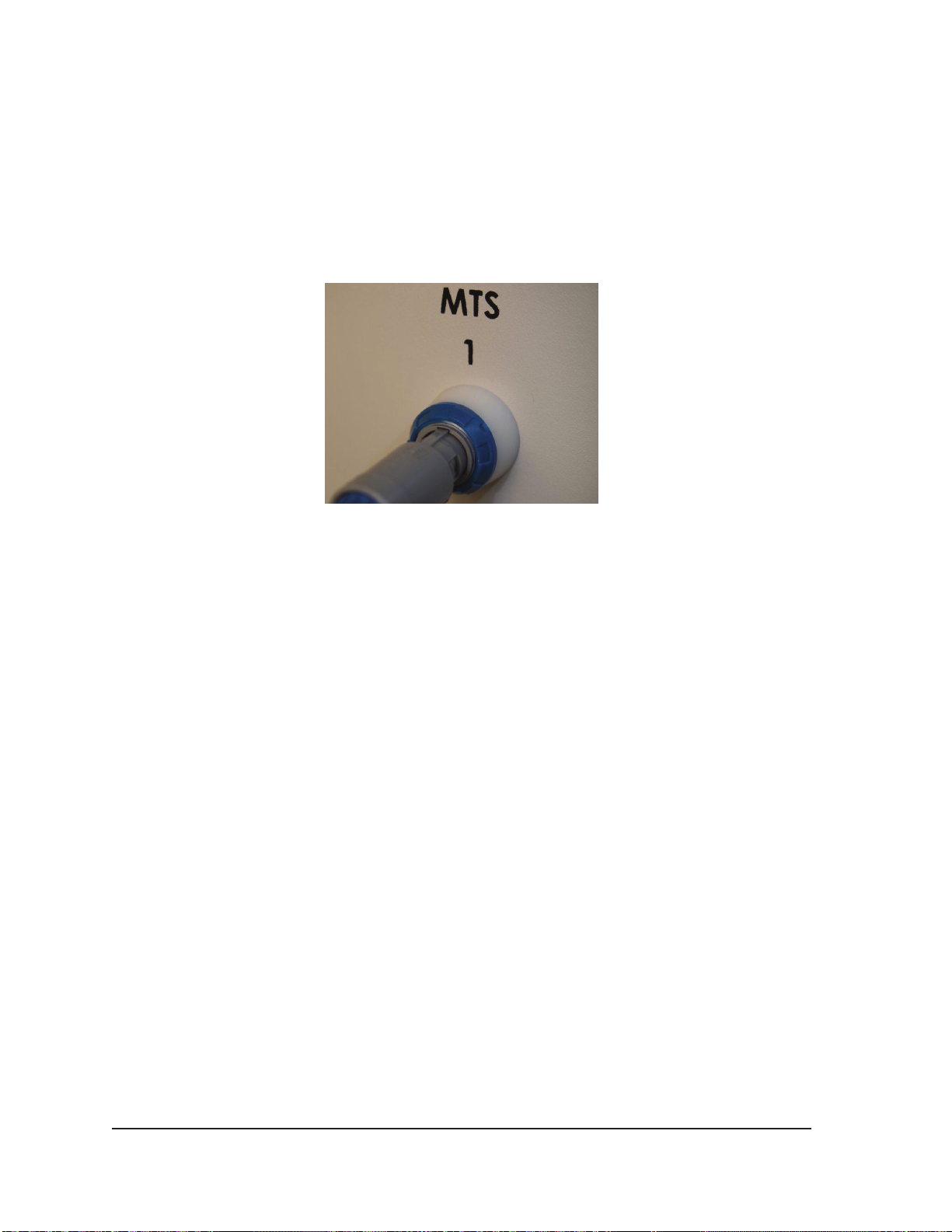
During the Needle Integrity and Functionality Test, the Gas Indicators for both gases provide
estimates of the time remaining before depletion of the cylinders assuming that all connected
needles are operated simultaneously (reference Section 3.3.1).
12. When using Multi-Point Thermal Sensors (MTS), prepare the desired number of sensors for
testing. The Visual-ICE System supports use of four thermal sensors. Connect each thermal
sensor to an MTS connection port by pushing the connector into the port. Ensure that the
rectangular tongue on the MTS connector is aligned with the groove at the top of the connection
port for proper MTS insertion (Figure 4-5).
Figure 4-5. MTS Connection
13. Conrm MTS functionality by verifying that the connected sensor produces a reasonable onscreen temperature reading (e.g., close to room temperature) in the Temperature Sensor section
of the software screen.
CAUTION. Do not use an MTS that has failed the thermal sensor functionality testing; erroneous
temperature measurements may be displayed.
CAUTION. Do not allow the MTS to touch the cryoablation needle during use; erratic
temperature measurements may be displayed.
4.2 Performing a Cryoablation Procedure
WARNING. Do not touch the screen if the touch-screen monitor goes blank for more than
ve (5) seconds during a procedure. Immediately turn o power to the system and end the
procedure to avoid inadvertent activation of needles.
1. OPTIONAL: On the Procedure Screen, select the Registration button to enter optional patient
treatment information. Use the stylus or your nger to enter information on the virtual keyboard.
Available data entry elds are Patient ID, Hospital Name, Hospital Address, Physician Name, and
Organ Type. If you need to enter any other registration information, two custom elds can be
labeled in the Congure Settings Screen (reference Section 5.1).
NOTE: The Visual-ICE System automatically loads the appropriate Organ Map based on the
Organ Type selected on the Registration button.
CAUTION. Select a unique Patient ID that does not reveal the patient’s identity to other system
users.
2. OPTIONAL: Select the Notes button on the Procedure Screen to enter additional procedure
notes. Notes can be entered at any time during the cryoablation procedure.
4-14 User Manual
Page 61
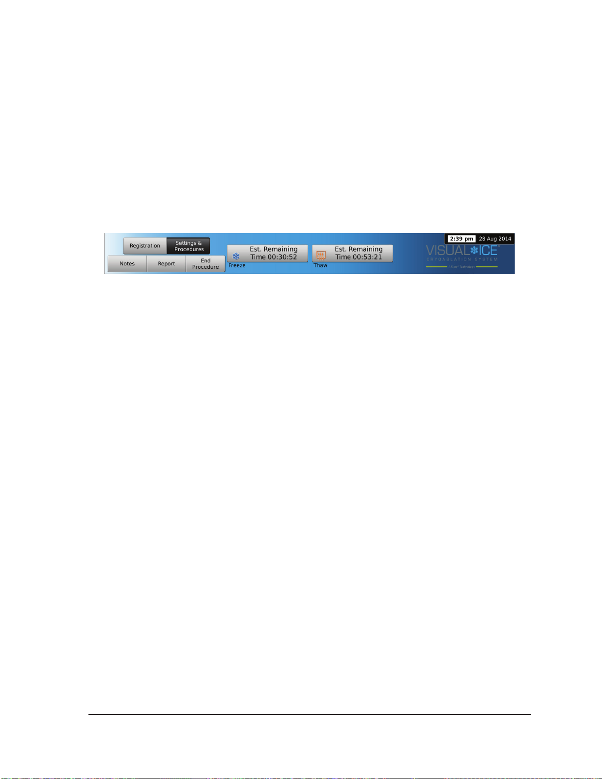
3. Position the cryoablation needles and thermal sensors in the target tissue.
CAUTION. During use, avoid damage to the needle from other surgical instruments.
OPTIONAL: Reference Section 3.3.8 for instructions on placing needles and thermal sensors on
the Organ Map.
CAUTION. Use image guidance to verify that the cryoablation needles are placed at the desired
location prior to activating a needle.
4. Select the desired Freeze Intensity using the drop-down menu.
NOTE: Throughout the procedure, monitor the amount of gas time remaining in the cylinders
using the Gas Indicator on the Navigation Tool Bar (Screen 4-14). If it is necessary to change
the gas cylinders during a procedure, follow the instructions provided in Section 4.5.
Screen 4-14. Gas Time Remaining
5. Press the Freeze button on selected channels containing needles to begin the initial freeze phase
of the procedure.
To adjust the freeze intensity, press the Freeze Intensity button and select the desired intensity
from the drop-down menu. The Freeze cycle will continue at the selected freeze level until this
operation is changed or stopped.
CAUTION. Continuously monitor iceball formation using image guidance such as direct
visualization, ultrasound, or Computed Tomography (CT) to ensure adequate tissue coverage and
to avoid damage to adjacent structures.
OPTIONAL: To initiate a freeze phase on all needles simultaneously, press the Freeze button on
the channel labeled ALL. Pressing any function button on the channel labeled ALL displays a
message asking you to conrm simultaneous operation of all needles.
NOTE: Selecting ALL will initiate a Freeze phase at the intensity selected for each channel.
To conduct freezing in all active channels at the same intensity, select the intensity in the ALL
channel before pressing the Freeze button.
6. Watch the timer to monitor the freeze phase elapsed time (reference Section 3.3.5 for instructions
on enlarging the timer display). When the desired freeze duration has elapsed, press the Stop
button to enter an idle phase.
7. If thermal sensors are used, monitor the tissue temperature using the Temperature Sensors
section of the Procedure Screen (reference section 3.3.7).
8. To actively thaw the iceball, press the Thaw button on the channels containing needles to start
the thaw phase.
If the Visual-ICE System detects that helium gas is connected, the system defaults to helium thaw
mode. If needles of mixed type (some helium thaw and some i-Thaw) are connected, the system
also defaults to helium thaw mode.
NOTE: Thawing with i-Thaw is limited to a maximum of 9 needles simultaneously.
Visual-ICE™ Cryoablation System
4-15
Page 62

NOTE: When thawing with CX-type needles, thawing is limited to a maximum of 7 needles
simultaneously activated. Thawing with the FastThaw function is limited to a maximum of 4
needles simultaneously (reference Section 4.6.1 for instructions on using i-Thaw and FastThaw).
OPTIONAL: To initiate a thaw phase on all needles simultaneously, press the Thaw button on the
channel labeled ALL. Pressing any function button on channel labeled ALL displays a message
asking you to conrm simultaneous operation of all needles.
9. Watch the timer to monitor the thaw phase elapsed time (reference Section 4.7.3 for instructions
on performing a timed thaw phase). When the desired thaw duration has elapsed, press the
Stop button to enter an idle phase.
10. Repeat steps 4 through 9 until the desired number of freeze-thaw cycles has been completed.
CAUTION. Ensure adequate thawing before attempting to remove needles from the patient.
Discontinue all needle operation prior to needle removal to minimize risk of tissue injury.
11. Remove all needles and MTS from the patient.
12. Unlock the locking bar(s) and remove all needles and MTS from the needle connection panel.
Cut needles and MTS from the tubing.
13. Dispose of used needles and MTS in a biohazard container in accordance with hospital and
safety regulations.
14. When the procedure is complete, press the End Procedure button on the Procedure Screen.
Three messages appear requesting action:
• Conrmation to end the procedure – Press the Yes button to end the procedure.
• Request to save a report – Press the Yes button to save a report.
• Request to automatically vent the high-pressure gas – Press the Yes button to automatically
vent the system. The system prompts you to close the gas supplies before venting. The
automatic venting takes approximately 1 1/2 minutes. Before initiating automatic venting,
warn others in the vicinity to expect a venting noise.
CAUTION. If the needles are still connected, do not unlock the channels or disconnect the needles
from the needle connection panel while venting is in process.
4.3 Reports
At any time during a procedure, press the Report button on the Procedure Screen to view a summary
of the report information that has been saved up to that point.
At the end of a cryoablation procedure, a report summarizing the complete procedure can be saved
to the system and exported for use on a personal computer.
1. Press the Report button on the Procedure Screen.
2. When viewing a report, you may scroll through the report using the scroll bar on the right-hand
side of the screen or you may select a section to view by pressing the report section name on the
left-hand side of the screen.
3. Press the Export Report button to save the report to the Galil Medical USB ash drive. A
window appears for you to select the le format and le name. Enter the le name using the onscreen virtual keyboard. You may also choose to export the temperature sensor data in a le to
be used for further analysis.
4-16 User Manual
Page 63
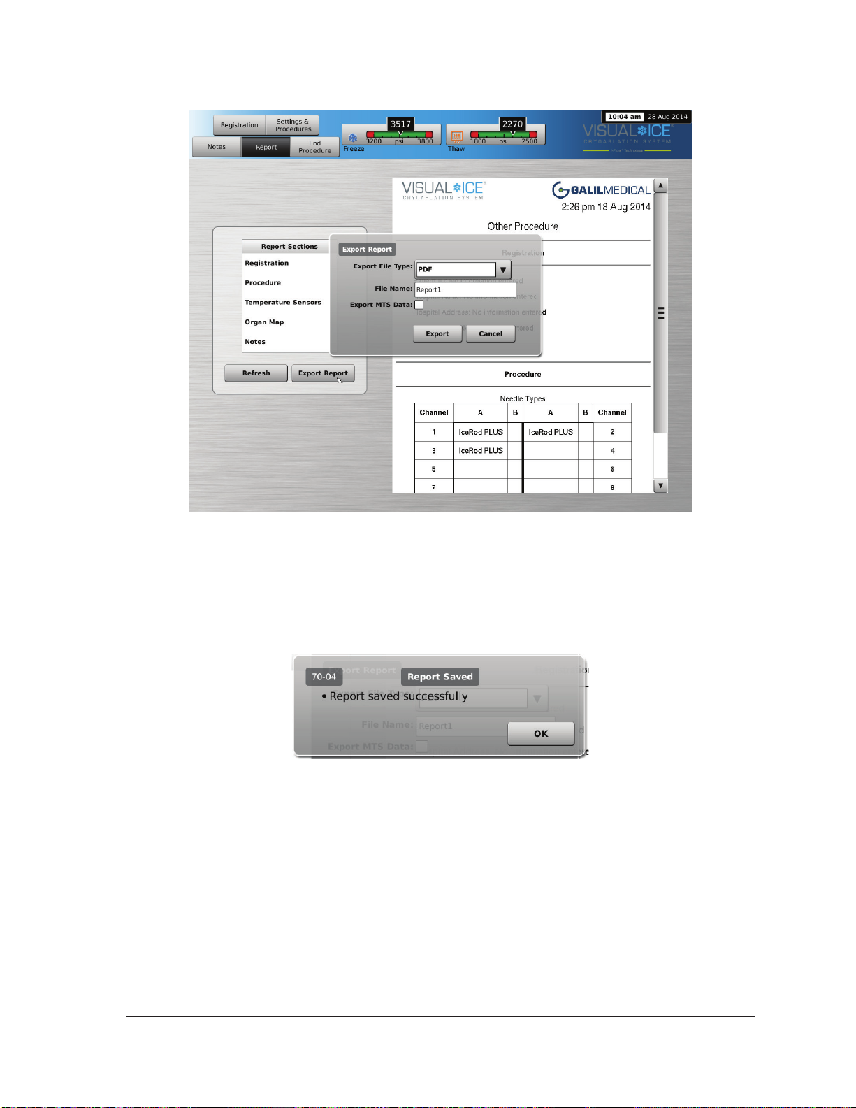
Screen 4-15. Export Report screen
CAUTION. Use only a Galil Medical supplied USB ash drive with the Visual-ICE System. Do
not use that ash drive for purposes unrelated to Visual-ICE System data and reports.
4. Press the Export button to begin exporting the le. Wait for conrmation before removing the
USB ash drive from the system.
Screen 4-16. Report Exported message
Visual-ICE™ Cryoablation System
4-17
Page 64

4.4 System Shutdown
WARNING. Warn operating room personnel prior to venting the Visual-ICE System to avoid
startling them.
1. If you did not choose to automatically vent the Visual-ICE Cryoablation System, turn the shuto
valve on the gas cylinders clockwise to close the gas cylinders.
2. Turn the Manual Vent Valve on the Visual-ICE System to the OPEN position to release the high
pressure gas from the system.
3. Disconnect the high-pressure gas supply lines from the Visual-ICE System and from the gas
cylinders. Store the gas supply lines and gauge assemblies in the storage compartment provided
on the system (Figure 2-1).
CAUTION. Do not use excessive force to disconnect the gas supply lines from the system.
The connectors will not disconnect if any gas pressure remains in the system. Vent the system
completely using the Manual Vent Valve and then try to disconnect the supply lines again.
4. Turn the Manual Vent Valve to the CLOSED position after the gas has been vented.
5. Press the Logout button on the Startup Screen to log out of the system.
6. Press the Shutdown button on the Login Screen to power down the system. A message appears
requesting conrmation to shut the system down.
7. Wait until the screen goes black. Turn the Power Control Knob to the OFF position.
8. Unplug the Visual-ICE System and wrap the power cord around the cord wrap on the rear of the
system.
WARNING. Do not pull on the power cord. Grasp the plug, not the power cord, to
disconnect the device from the wall socket.
9. Cover the helium and argon inlets with the humidity plugs.
10. Clean the system after each use using the instructions provided in Section 6.2. Ensure the
system is dry prior to storage.
11. Lower the Touch Screen Monitor into the monitor storage compartment prior to system storage.
CAUTION. Prior to lowering the monitor, ensure that no objects, such as the USB ash drive,
are located in the monitor storage compartment. Use care when lowering the monitor into the
storage compartment; do not use excessive force to avoid damaging the monitor.
CAUTION. Use care when lowering the touch screen monitor to avoid the potential for pinching
ngers.
12. Cover the Visual-ICE System with the Console cover.
4-18 User Manual
Page 65

4.5 Changing Gas Cylinders during a Procedure
If it becomes necessary to replace a gas cylinder during a procedure, stop all freezing and thawing
operations.
4.5.1 Standard Gas Cylinder Setup
1. Plan the appropriate time to make a cylinder change by estimating the gas required to complete
the procedure. The Gas Indicator on the Navigation Tool Bar indicates how much time is
remaining in each gas cylinder based on the selected gas ow intensity, type and number of
needles being used. Also, consider the number of planned freeze-thaw cycles for the procedure.
2. Safely position a full gas cylinder, with the required gas type and purity, near the empty cylinder.
3. Close and tighten the cylinder valves of both gas cylinders.
4. Slowly open the Manual Vent Valve to discharge gas from the system and the high pressure
gas supply line. Wait until all the pressure is released and both gauges on the gas supply lines
indicate zero pressure.
5. Use the wrench to remove the gauge assembly from the empty cylinder.
6. Connect the gauge assembly to the full cylinder.
7. Close and tighten the Manual Vent Valve.
8. Carefully turn the cylinder valve on the helium gas cylinder counter-clockwise for one quarter turn.
Ensure that the pressure reading on the gauge responds immediately. Turn the cylinder valve
further counter-clockwise to open the gas cylinder so that sucient gas ow is present.
9. Carefully turn the cylinder valve on the argon gas cylinder counter-clockwise for one quarter turn.
Ensure that the pressure reading on the gauge responds immediately. Turn the cylinder valve
further counter-clockwise to open the gas cylinder so that sucient gas ow is present.
If no argon pressure is displayed on the Gas Indicator, ensure the Argon Shuto Valve is OPEN.
10. Continue the cryoablation procedure at the next planned freeze or thaw phase.
4.5.2 Disconnecting a Helium Cylinder
If helium is connected, i-Thaw, FastThaw and Cautery functions are disabled. To use i-Thaw,
FastThaw, and Cautery functions, helium must be disconnected and the lines cleared of helium.
1. Close both the argon and helium cylinder valves.
2. Open the Manual Vent Valve to discharge gas from the system and the high pressure gas supply
lines. Wait until all the pressure is released and both pressure gauges on the Navigation Tool Bar
indicate zero pressure.
3. Close the Manual Vent Valve.
4. Slowly open the argon cylinder valve one quarter to one half of a turn. Allow pressure to build on
the argon pressure gauge. Open the argon cylinder valve fully for sucient argon ow.
Visual-ICE™ Cryoablation System
4-19
Page 66
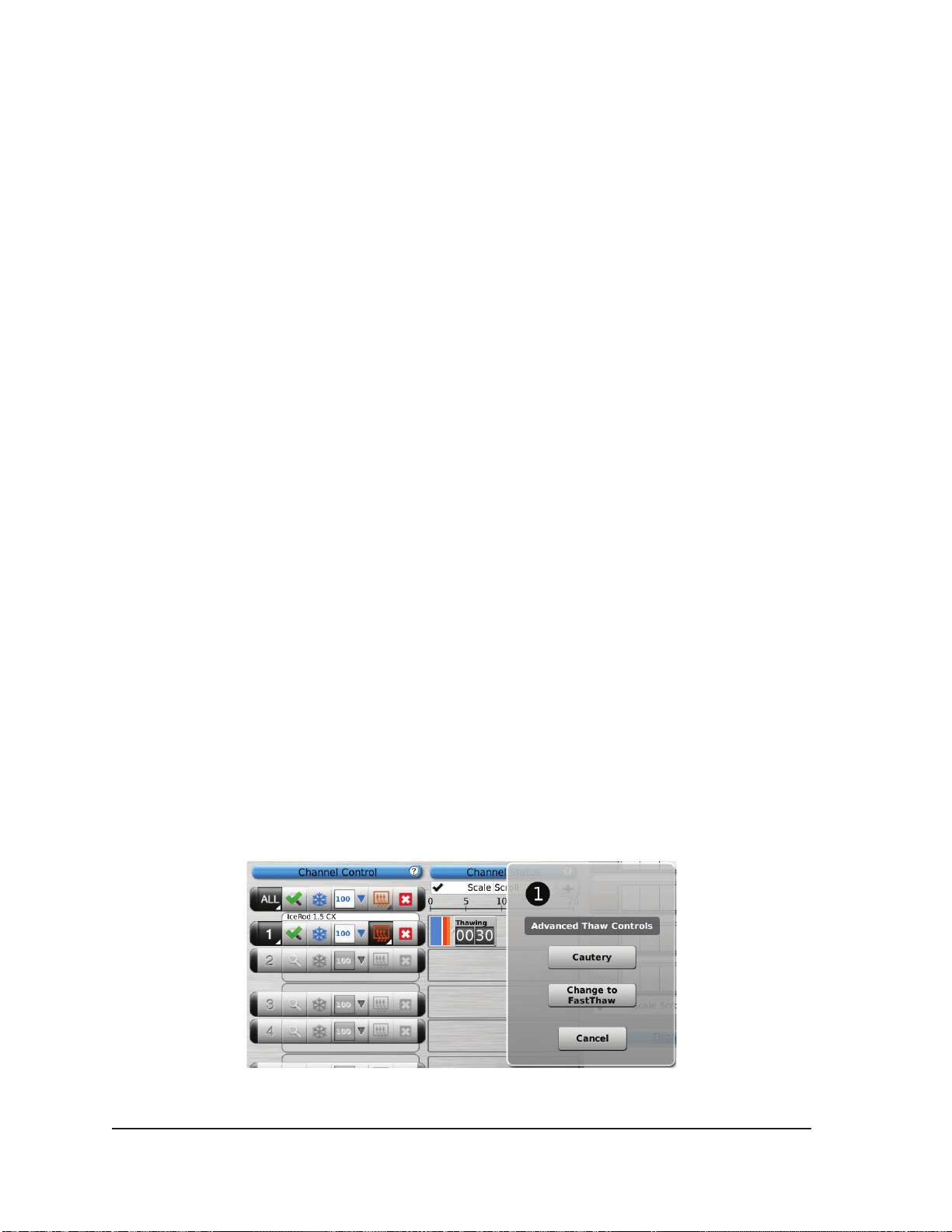
4.5.3 Dual Gas Cylinder Connection
1. Safely position a full argon gas cylinder, with the required purity, near the empty cylinder.
2. Close and tighten the cylinder valve of the empty gas cylinder.
3. Open the Manual Vent Valve to discharge gas from the system and the high pressure gas supply
lines. Wait until all the pressure is released and the pressure gauge(s) on the Navigation Tool Bar
indicate zero pressure.
4. Close the Manual Vent Valve.
5. Connect the auxiliary gas supply line to the EZ-Connect2 four-way adapter assembly using the
quick-connect connectors.
6. Connect the opposite end of the auxiliary gas supply line to the new cylinder.
7. Carefully turn the cylinder valve on the new gas cylinder counter-clockwise for one quarter turn.
Ensure that the pressure reading on the gauge responds immediately. Turn the cylinder valve
further counter-clockwise to open the gas cylinder so that sucient gas ow is present.
4.6 Advanced Thaw Controls
The Visual-ICE System provides options to select helium-free thawing (i-Thaw and FastThaw) and to
conduct track ablation (Cautery).
NOTE: i-Thaw, FastThaw and Cautery functions are only available when needles with that capability
are connected.
NOTE: Argon gas only must be connected to access these functions. Connecting helium gas to the
Visual-ICE System disables these functions.
4.6.1 i-Thaw and FastThaw Control for CX-type Needles
CAUTION. Active thawing produces heat along the distal needle shaft. Use care to avoid thermal
injury to non-targeted tissues.
CAUTION. The needle handle may become warm during active thawing. Pay attention to the needle
handle position. Prolonged contact with warm portions of the needle handle could cause unintended
thermal tissue damage to the patient or clinician.
1. Press and hold the Thaw button to access Advanced Thaw Controls (Screen 4-17). The
Advanced Thaw Controls menu provides access to i-Thaw / FastThaw and Cautery functions.
• When i-Thaw is operational, pressing the Change to FastThaw button in the Advanced Thaw
Controls will change the thaw from i-Thaw to FastThaw (Screen 4-17).
Screen 4-17. Advanced Thaw Controls FastThaw
4-20 User Manual
Page 67
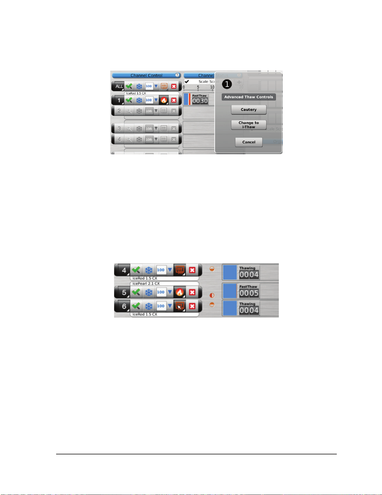
• Similarly, when FastThaw is selected, pressing the Change to i-Thaw button will change the
thaw from FastThaw to i-Thaw (Screen 4-18).
Screen 4-18. Advanced Thaw Controls i-Thaw
2. After selecting the type of thaw, press the Thaw or FastThaw button in the Channel Control to
initiate thawing.
NOTE: The FastThaw function generates a temperature that is higher than that generated for
i-Thaw, resulting in a faster thaw time.
NOTE: A maximum of 7 needles can thaw simultaneously using the i-Thaw function; a maximum
of 4 needles can thaw simultaneously using the FastThaw function.
3. During the needle warming phase for CX-type needles, the channel status will display a rotating
warming indicator (Screen 4-19).
Screen 4-19. Advanced Thaw - Needle Warming
4. When the threshold temperature for i-Thaw or FastThaw is reached, the channel status will
display the estimated temperature range for the needle shaft (Screen 4-20).
NOTE: The shaft temperature is displayed as a temperature range because tissue and
procedural variables will aect the temperature.
Visual-ICE™ Cryoablation System
4-21
Page 68
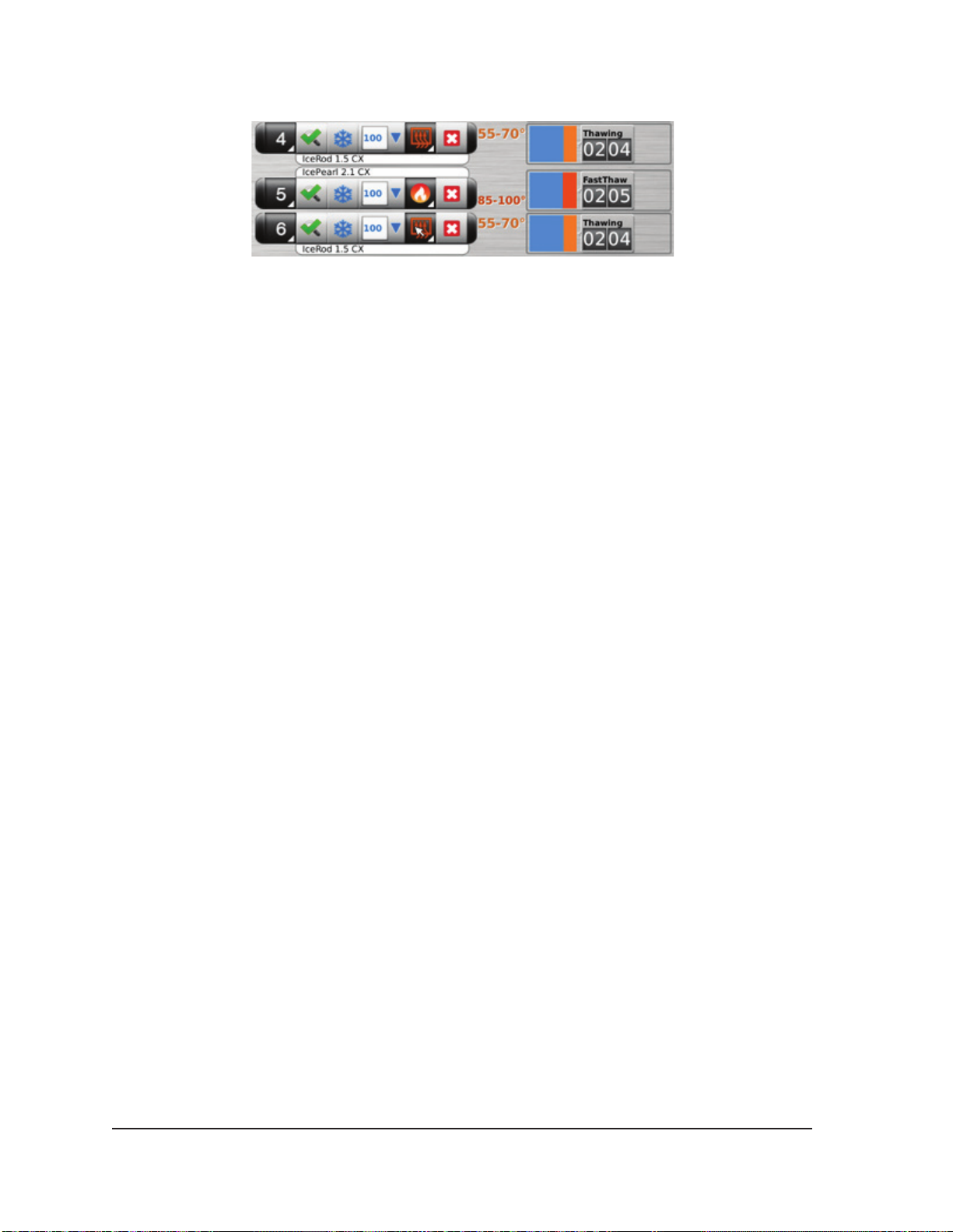
Screen 4-20. Advanced Thaw - Temperature Display During Thawing
5. Thaw thoroughly and stop all needle operation prior to removing needles to minimize the risk of
tissue injury.
• If needle sticking is experienced, use a slight, gentle twist of the needle followed by slow
withdrawal.
4.6.2 Cautery Control for Track Ablation
Needle track ablation is achieved using the Cautery function in the Advanced Thaw Controls. The
needle track is ablated through the use of thermal energy. Each cautery enabled needle (1.5 CXtype needles and 2.1 CX-type needles) is operated independently using the Cautery button in the
Advanced Thaw Controls for the channel and port in which the needle is connected.
CAUTION. Use image guidance to monitor needle location and position to avoid the risk of thermal
injury to adjacent tissue / organs.
CAUTION. Track ablation produces heat along the distal needle shaft. Use care to avoid thermal
injury to adjacent tissue / organs.
CAUTION. The needle handle may become warm during track ablation. Pay attention to the needle
handle position. Prolonged contact with warm portions of the needle handle could cause unintended
thermal tissue damage to the patient or clinician.
CAUTION. The Cautery function should not be initiated if the Active Zone Indicator is visible outside
the patient’s skin.
NOTE: While the Visual-ICE System is in cautery mode, freezing and thawing are not allowed on any
other channels.
NOTE: The Cautery function is not available on the channel ALL.
4.6.2.1 Cautery Control for 1.5 CX Needles
1. Press and hold the Thaw button to access Advanced Thaw Controls.
2. Press the Cautery button on the Advanced Thaw Controls menu to open the Cautery Control
Screen (Screen 4-17). A conrmation message appears (Screen 4-21).
4-22 User Manual
Page 69
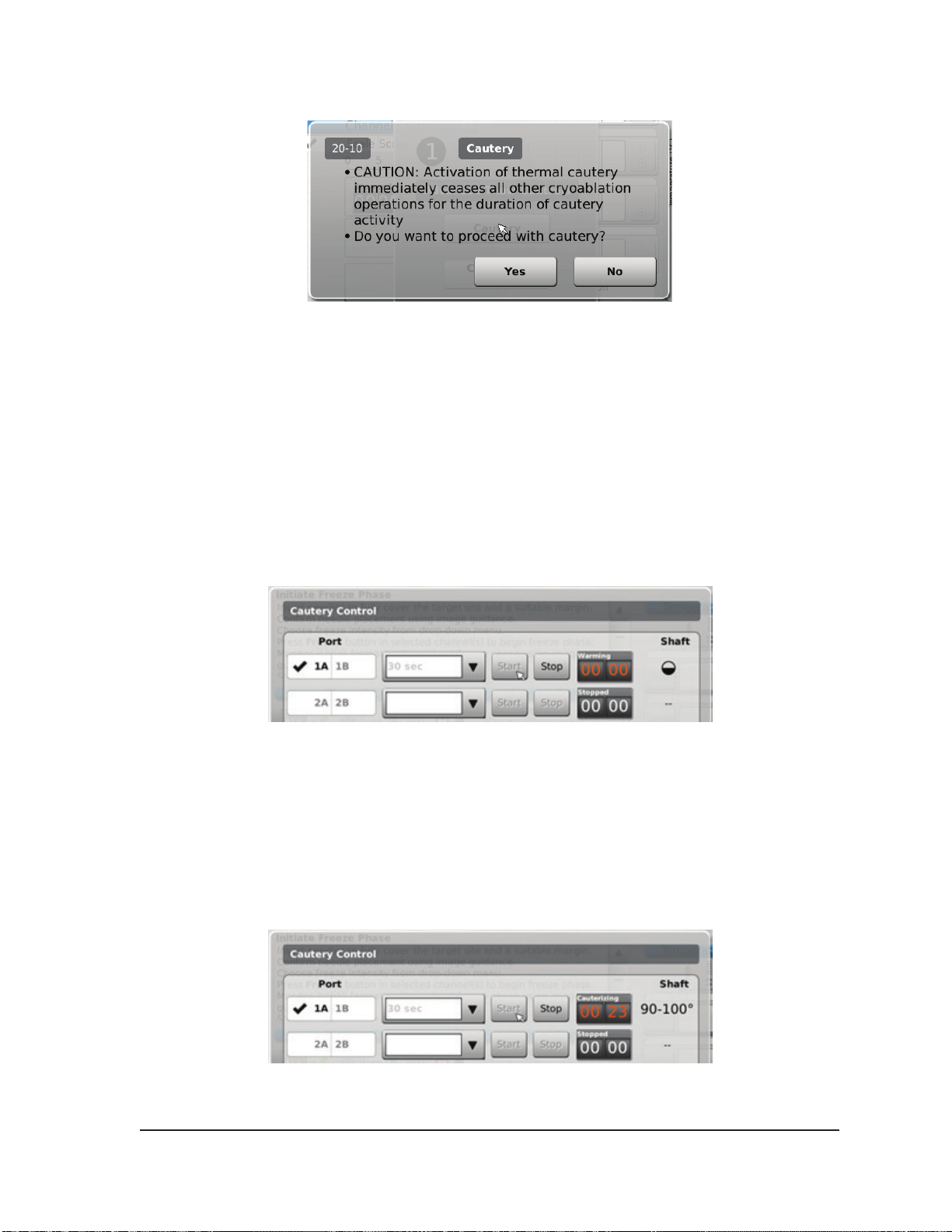
Screen 4-21. Cautery Conrmation message
3. Press the desired needle port (A or B) on each channel containing a needle you wish to track
ablate. Only one needle per channel may activate the cautery function at a given time.
NOTE: The Visual-ICE System uses a pre-set duration of 30 seconds for each cautery phase for
1.5 CX-type needles. This value is not adjustable, but the duration can be stopped in advance of
30 seconds by pressing the Stop button.
NOTE: A maximum of four (4) needles may use the cautery function simultaneously.
4. Press the Start button to initiate track ablation (Cautery).
• During the needle warming phase, the Cautery Control Screen will display a rotating warming
indicator (Screen 4-22).
Screen 4-22. 1.5 CX Needle Warming
• When the cautery threshold temperature is reached, Cauterization automatically begins.
o The timer will display Cauterizing (Screen 4-23).
o The Cautery Control Screen will display the estimated temperature range for the needle
shaft.
NOTE: The shaft temperature is displayed as a temperature range because tissue and
procedural variables aect the temperature.
Screen 4-23. 1.5 CX Needle Cautery In Progress
Visual-ICE™ Cryoablation System
4-23
Page 70

• When the cautery function has terminated, the timer indicates the status as Stopped and the
temperature display indicates that the needle is Cooling.
5. If desired, press the Start button to re-initiate track ablation on additional sections of the needle
track.
6. After completing track ablation, carefully remove the needle.
CAUTION. Do not remove the needle from the patient until needle cooling is complete.
Removing the needle while it is still hot presents a risk of injury to adjacent tissue and/or organs.
• If needle sticking is experienced, use a slight, gentle twist of the needle followed by slow
withdrawal.
• During needle removal, watch for the 10 mm wide Active Zone Indicator on the needle to
guide needle withdrawal. The Active Zone Indicator is a marked band along the needle shaft,
located 20 mm distal to the heating portion of the needle.
4.6.2.2 Cautery Control for 2.1 CX Needles
1. Press and hold the Thaw button to access Advanced Thaw Controls.
2. Press the Cautery button on the Advanced Thaw Controls menu to open the Cautery Control
screen (Screen 4-17). A conrmation message appears (Screen 4-21).
3. Press the desired needle port (A or B) on each channel containing a needle you wish to track
ablate. Only one needle per channel may activate the cautery function at a given time.
NOTE: A maximum of four (4) needles may use the cautery function simultaneously.
NOTE: The duration for the cautery phase for 2.1 CX-type needles may be selected from 30
seconds to 3 minutes, adjustable in 30 second increments. If a 2.1 CX-type is connected, a
drop-down menu will provide cautery duration choices.
4. Select the cautery duration from the drop-down menu.
5. Press the Start button to initiate track ablation (Cautery).
• During the needle warming phase, the Cautery Control Screen will display a rotating warming
indicator (Screen 4-22).
• When the cautery threshold temperature is reached, Cauterization automatically begins.
o The timer will display Cauterizing (Screen 4-23).
o The Cautery Control Screen will display the estimated temperature range for the needle
shaft.
NOTE: The shaft temperature is displayed as a temperature range because tissue and
procedural variables aect the temperature.
• When the cautery function has terminated, the timer indicates the status as Stopped and the
temperature display indicates that the needle is Cooling.
6. If desired, press the Start button to re-initiate track ablation on additional sections of needle track.
7. After completing track ablation, carefully remove the needle.
CAUTION. Do not remove the needle from the patient until needle cooling is complete.
Removing the needle while it is still hot presents a risk of injury to adjacent tissue and/or organs.
• If needle sticking is experienced, use a slight, gentle twist of the needle followed by slow
withdrawal.
• During needle removal, watch for the 10 mm wide Active Zone Indicator on the needle to
4-24 User Manual
Page 71
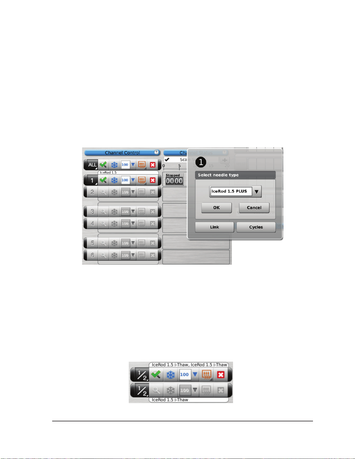
guide needle removal. The Active Zone Indicator is a marked band along the needle shaft,
located 20 mm distal to the heating portion of the needle.
4.7 Advanced Channel Controls
Advanced Channel Controls for each channel provide options to change the needle type for the
selected channel, link two channels together, and program multiple freeze-thaw cycles.
4.7.1 Select Needle Type Control
1. To change the needle type for a channel, press and hold the Channel button to enter Advanced
Channel Controls for that channel (Screen 4-24).
2. Select the proper needle type from the drop-down menu.
3. Press the OK button.
Screen 4-24. Advanced Channel Controls
4.7.2 Link Channels Control
1. Press and hold the Channel button to enter Advanced Channel Controls for that channel
(Advanced Channel Controls).
2. Press the Link button to link two channels together for simultaneous operation. When two
channels are linked, the Channel button shows both channels (Screen 4-25).
NOTE: This function is not available on the channel labeled ALL. You can only link channels
that are on the same horizontal plane on the Needle Connection Panel (e.g., 1 and 2, 3 and 4,
5 and 6).
Screen 4-25. Linked Channels
Visual-ICE™ Cryoablation System
4-25
Page 72
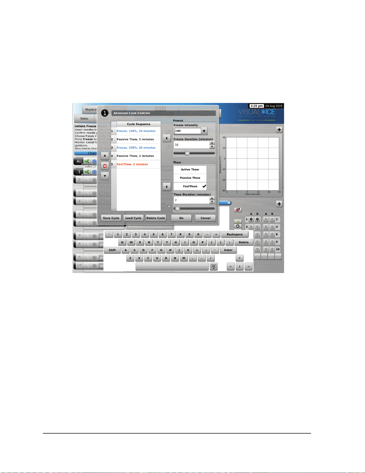
3. Press the Unlink button (accessed by pressing and holding the Channel button) to remove the
link between two channels so that each operates independently.
4.7.3 Cycle Programming Control
1. Press and hold the Channel button to enter Advanced Channel Controls for that channel.
2. Press the Cycles button (Advanced Channel Controls) to enter Advanced Cycle Controls to
program freeze-thaw cycle(s) (Screen 4-26).
Screen 4-26. Advanced Cycle Controls
3. Select the desired freeze intensity from the Freeze controls using the drop-down menu and the
freeze phase duration using the appropriate arrow or the scroll bar.
4. Add the programmed freeze cycle to the Cycle Sequence menu using the left Arrow button next
to the Freeze controls.
5. Select the desired thaw by clicking on the available options in the Thaw controls. Select the thaw
duration using the appropriate arrows or the scroll bar.
6. Add the programmed thaw cycle to the Cycle Sequence menu using the left Arrow button next to
the Thaw controls.
7. Program additional cycles by repeating steps 3 – 6 as appropriate.
8. Arrange the cycle sequence by highlighting a programmed cycle on the Cycle Sequence controls.
Using the Up or Down button, move the cycle into the desired sequence.
9. Remove a cycle from the Cycle Sequence by highlighting the cycle then pressing the Stop
button.
10. Press the Go button to initiate the cryoablation procedure with the programmed cycles.
CAUTION. Any interruption of a programmed phase immediately terminates that phase and the
programmed cycle.
4-26 User Manual
Page 73
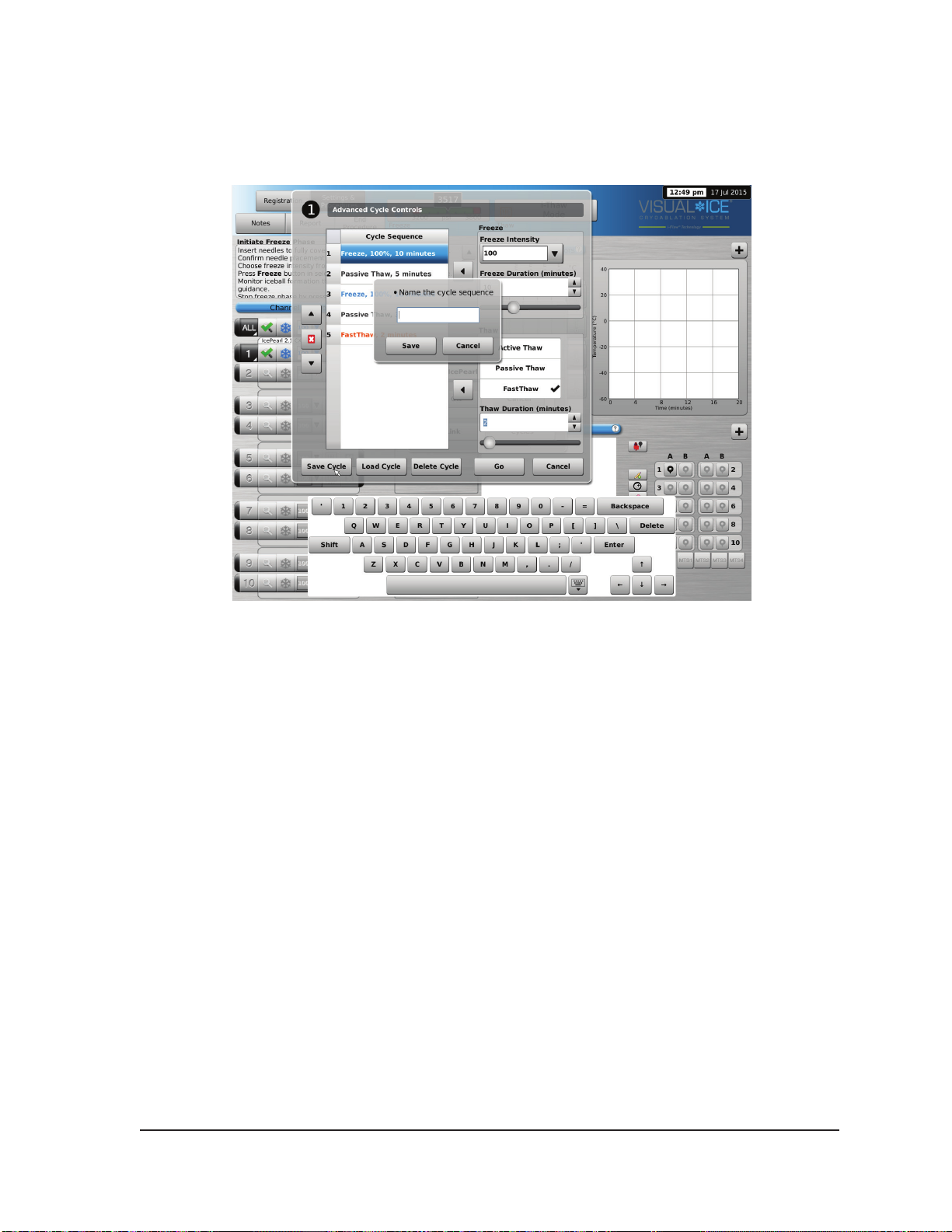
11. Repeat steps 1 to 10 to program additional channels.
NOTE: Programmed sequences may be saved by selecting the Save Cycle button. Name the
sequence, then press the Save button (Screen 4-27).
Screen 4-27. Cycle Sequence Controls
Visual-ICE™ Cryoablation System
4-27
Page 74
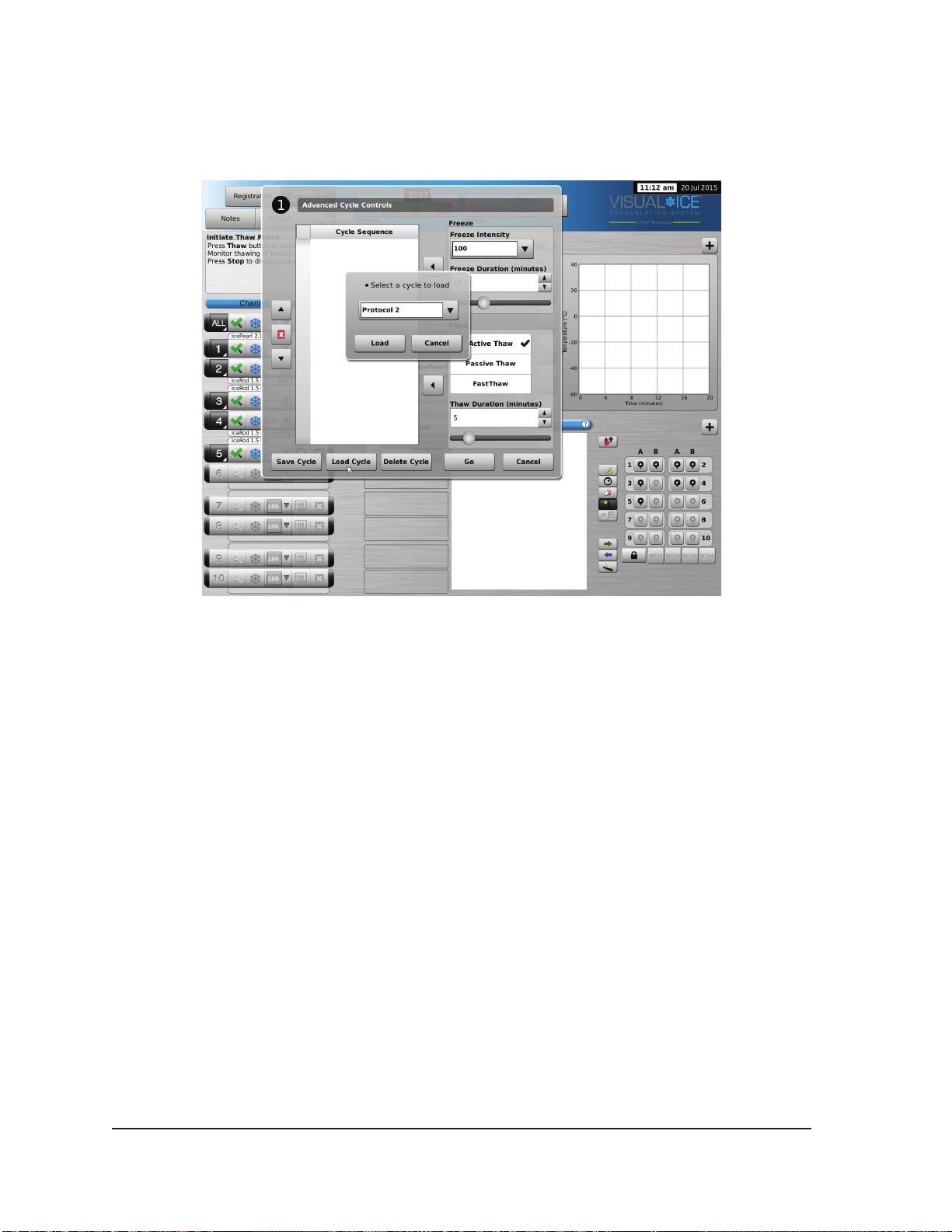
To run a saved sequence, enter Advanced Channel Controls for the selected channel, press the
Cycles button and press the Load Cycle button. Using the drop-down menu, select the saved
sequence, press the Load button, then press the Go button (Screen 4-28).
Screen 4-28. Saved Sequence Controls
4-28 User Manual
Page 75
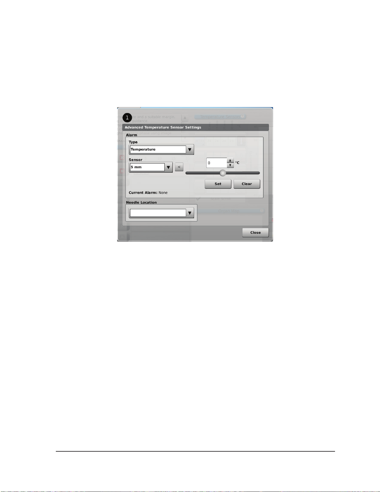
4.8 Advanced Temperature Sensor Controls
The advanced temperature sensor controls provide an option to set visual alarm notications when
a chosen temperature measurement on an MTS falls below a desired value or when the rate of
temperature drop is greater than a desired value for a select MTS sensor location.
1. Press and hold the MTS Channel button (Screen 3-10) for a selected MTS to enter Advanced
Temperature Sensor Settings.
Screen 4-29. Advanced Temperature Sensor Controls
2. Select the desired alarm type and desired sensor location using the drop-down menus.
3. Press the Up or Down button and adjust the temperature to dene the desired alarm limit.
4. Press the Set button to set the alarm.
OPTIONAL: Select a name to be displayed above the MTS channel location using the Needle
Location drop-down menu. The list of needle names provided is derived from the list available in the
Congure Settings Screen (reference Section 5.1) and is associated with the selected organ map.
Visual-ICE™ Cryoablation System
4-29
Page 76

This page intentionally left blank.
4-30 User Manual
Page 77
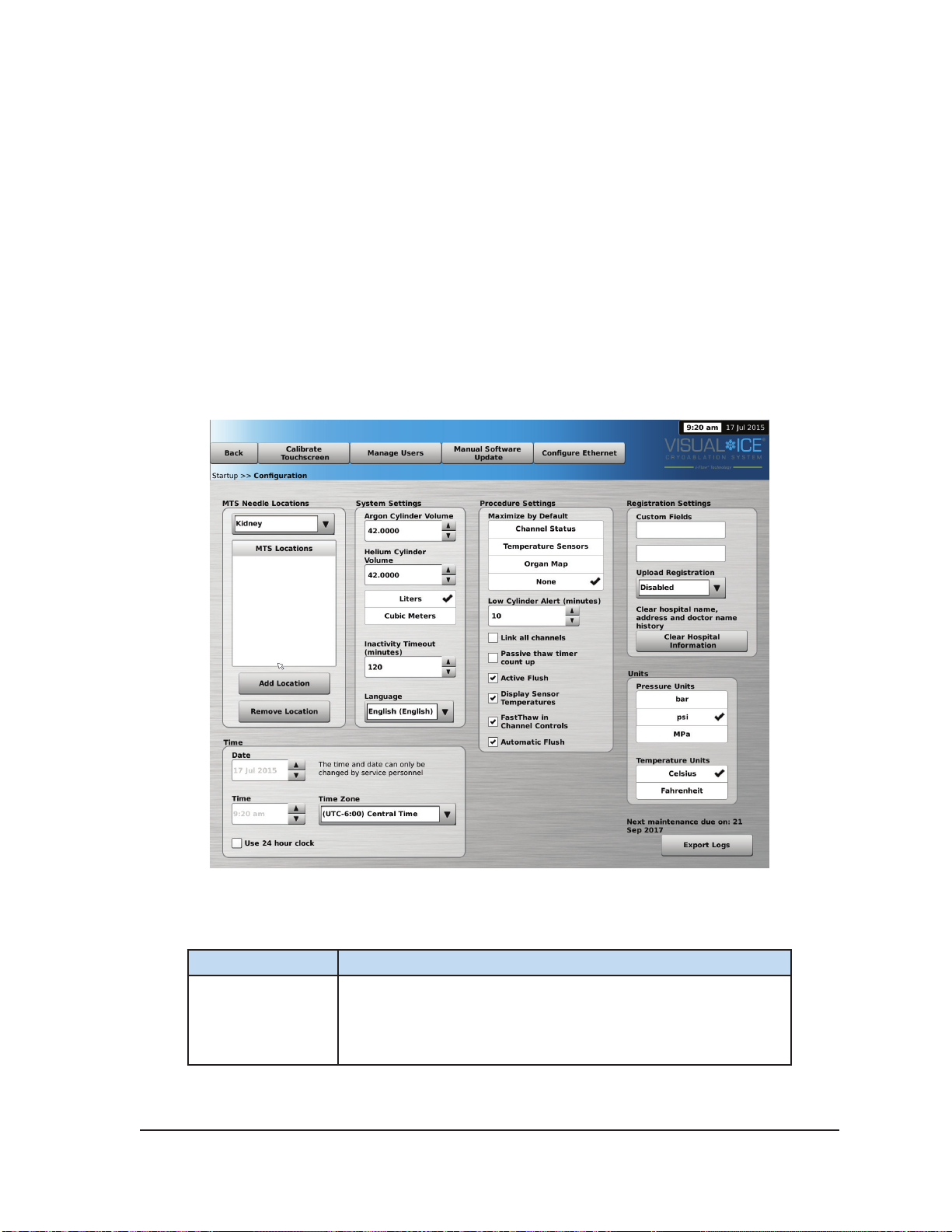
5 ADMINISTRATIVE FUNCTIONS
5.1 Congure Settings
The Congure Settings Screen allows you to change system settings used during a cryoablation
procedure. A maximum of ve (5) user accounts can be congured for each Visual-ICE™ System.
Settings that may be changed include MTS Needle Locations, System, Procedure and Registration
Settings and Units (reference Table 5-1). Only Service personnel have the option to adjust the
system time and date; System Administrators can change the Time Zone.
When settings have been changed, press the Back button to return to the Startup screen. A
message is displayed summarizing the changes made to the settings and asking for conrmation to
save the settings. Press Yes to save the settings, No to exit the screen without saving your changes,
or Cancel to return to the Congure Settings Screen and continue making changes.
Table 5-1. Congure Settings Controls
Setting Description
Customize the list of names to be provided for the MTS needles
MTS Needle
Locations
Visual-ICE™ Cryoablation System
for each associated organ map. Press Add Location to add
a new name to the list. Press Remove Location to delete a
name from the list.
Screen 5-1. Congure Settings
5-1
Page 78
Setting Description
Select the gas cylinder volume and units of measure according
Cylinder Volume
Inactivity Timeout
Language Select the language in which the software is displayed.
to the standard in the geographical region. The gas cylinder
volume and units can only be changed by administrative or
service personnel.
Select the desired duration from 30 to 180 minutes that the
system can be inactive before requiring you to re-enter your
password. The default inactivity timeout is two hours.
Maximize by
Default
Low Cylinder Alert
Link all channels
Passive thaw
timer count up
Active Flush
Display Sensor
Temperatures
Select a section of the Procedure Screen to be maximized by
default at login.
Select the desired reminder interval (0 to 15 minutes) for the
Gas Indicator to display an alert that the estimated remaining
volume in the gas cylinder is low.
Check this box to automatically link all adjacent channels for
simultaneous operation (e.g., 1 and 2, 3 and 4, 5 and 6, …)
Check this box to automatically display elapsed time during
passive thaw. The digital timer reads Stopped and the time
elapsed in passive thaw is indicated.
Unless disabled by removing the check from this box, an
automated active 30 second ush will follow a freeze cycle
conducted at 50% or higher intensity and lasting greater than 3
minutes.
Check this box for a Channel Status display of the internal
gas temperature at the needle tip during freeze phase and the
estimated temperature range of the needle shaft during active
thaw phases for i-Thaw and CX-type needles.
FastThaw in
Channel Controls
5-2 User Manual
Check this box for display of the FastThaw™ icon in the
Channel Controls when the system is in i-Thaw™ mode and a
FastThaw capable needle is connected.
Page 79
Setting Description
Unless disabled by removing the check from this box, an
Automatic Flush
automated gas line ushing will occur after argon is connected
and the gas lines pressurized.
Custom Fields
Upload
Registration
Clear Hospital
Information
Time Zone
Pressure Units Select the units of pressure that the Gas Indicator displays.
Temperature Units
Enter custom names to label the two custom elds available for
entering information in the Registration screen.
Use the drop-down menu to enable or disable the option to
upload registration data with the procedure reports. By default,
registration data is not uploaded. This function is only available
to administrative or service personnel.
Clear the hospital name, address, and physician name from the
system history le.
The time zone can be changed by administrative or service
personnel. The Visual-ICE System automatically adjusts for
Daylight Saving Time.
Select the temperature units that the Temperature Sensors
section displays and graphs.
Control buttons at the top of the screen provide options for Calibrate Touch Screen, Manage Users,
Manual Software Update, and Congure Ethernet.
Calibrate Touch Screen: Press the center of the ‘+’ symbols to calibrate the touch screen. Follow
the on-screen prompts as you move from one location to another. The system begins the calibration
process by displaying a ‘+’ symbol in the upper left-hand area of the touch screen. The ‘+’ symbol
then moves counter-clockwise to the lower left, lower right, and upper right-hand areas of the screen.
The nal calibration location is in the center of the screen.
Manage Users: Select your username and press the Change Password button to change your
password. Administrative users may add users, remove users, or change the password of any user.
Manual Software Update: Press the Manual Software Update button to install a software update
via a Galil Medical USB ash drive. This function is available only to administrative and service
users.
Congure Ethernet: Pressing this button allows administrative and service users to congure
the Ethernet connection for remote uploading of reports or downloading of software versions. This
function is available only to administrative and service users.
Visual-ICE™ Cryoablation System
5-3
Page 80
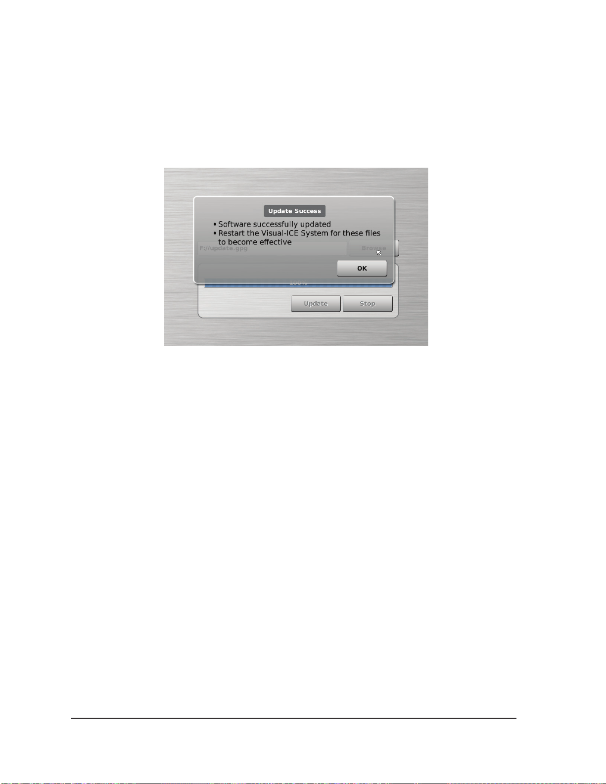
5.1.1 Manual Software Update
Administrative and service users can manually update the Visual-ICE System software via a Galil
Medical USB ash drive.
1. Press the Manual Software Update button on the Congure Settings Screen (Screen 5-1).
2. Press the Browse button to select the update le and press Update. A conrmation message
appears when the software update is complete (Screen 5-2).
Screen 5-2. Software Update Conrmation
NOTE: All users can update the software using the Remote Upload / Download button on the
Startup Screen (reference Section 3.5)
5.1.2 Congure Ethernet
The Visual-ICE System must be congured to access one of two Galil Medical servers for remote
uploading of reports and downloading of software updates. This function is only available to
administrative and service users.
The Visual-ICE System may be congured to use a static IP address or work with a DHCP server to
obtain the address dynamically. Consult the network administrator about proper network access prior
to conguring the system.
5-4 User Manual
Page 81

6 SYSTEM CARE and MAINTENANCE
6.1 System Installation
Installation instructions for the Visual-ICE™ System are included in the shipping carton, available
online at www.galilmedical.com/customerservice, or by contacting your local Galil Medical
representative.
6.2 Cleaning
6.2.1 Cleaning the Visual-ICE System
Clean the Visual-ICE Cryoablation System after each use by following the steps below.
1. Clean the Touch Screen Monitor when the Visual-ICE Cryoablation System is powered OFF.
• Wipe the screen gently with a damp gauze wipe.
• Use water or isopropyl alcohol only.
• Do not use cleaning agents such as Betadine or bleach solution.
2. Clean the Visual-ICE Cryoablation Console by wiping with a damp gauze wipe.
• Use soap and water or isopropyl alcohol cleaning solutions.
• Do not use cleaning agents such as Betadine or bleach solution.
• Do not allow water or other liquid to drip or seep inside the cryoablation needle connection
ports. The needle connection ports must remain completely dry at all times.
3. Ensure that cleaned surfaces are dry prior to closing or turning on the system.
CAUTION. Do not set food, drinks, or other objects on top of the Visual-ICE Cryoablation System.
Doing so may damage the system.
6.2.2 Cleaning the Stylus
Clean the stylus after each use by wiping down with isopropyl alcohol. Dry the stylus with a dry
gauze wipe.
6.3 Service and Preventive Maintenance
Only trained and authorized service engineers are permitted to conduct service and system
preventive maintenance on the system. Preventive maintenance on the Visual-ICE Cryoablation
System will be performed every two years.
CAUTION. Do not attempt to service the Visual-ICE Cryoablation System. If service is required,
contact Galil Medical Customer Service.
The Visual-ICE Cryoablation System will display a reminder on the screen approximately one
month prior to when the preventive maintenance is due. If the reminder message appears and the
preventive maintenance has not yet been scheduled, contact your Galil Medical authorized service
representative to schedule the service.
Visual-ICE™ Cryoablation System
6-1
Page 82

6.4 Technical Information
If additional technical information is required, place a request with a Galil Medical qualied service
engineer.
6.5 System Disposal
In compliance with Waste Framework Directives, when a Visual-ICE System is decommissioned,
contact Galil Medical Customer Service to schedule system replacement, refurbishing or disposal.
6-2 User Manual
Page 83
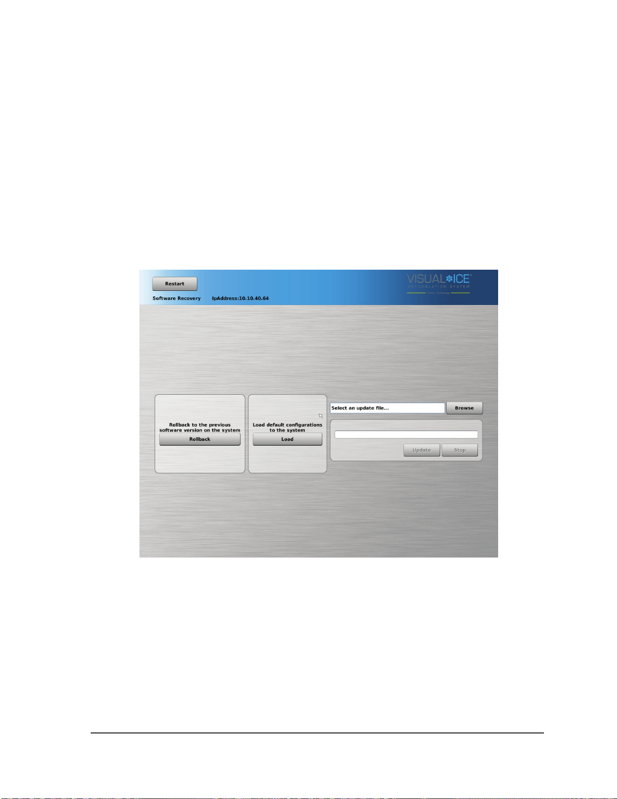
7 TROUBLESHOOTING
Galil Medical suggests the following options for troubleshooting the Visual-ICE™ System. If the
suggested approaches do not resolve the issue, contact Galil Medical Customer Service.
7.1 Software Recovery
In the event of software corruption or failure, the software may be restored to the previous software
version. Administrative and service users may update the software with an appropriate USB ash
drive.
1. Shutdown the Visual-ICE System.
2. Hold down the Software Reset button by inserting a straightened paper clip into the Software
Reset hole while simultaneously powering up the system. The system displays the Software
Recovery Screen.
Screen 7-1. Software Recovery Screen
3. Press the Rollback button to restore the software to the previous software version.
4. OPTIONAL: Press the Load button to update the software if the screen displayed a message
indicating that the software conguration is invalid on the login screen (Screen 7-2).
Visual-ICE™ Cryoablation System
7-1
Page 84
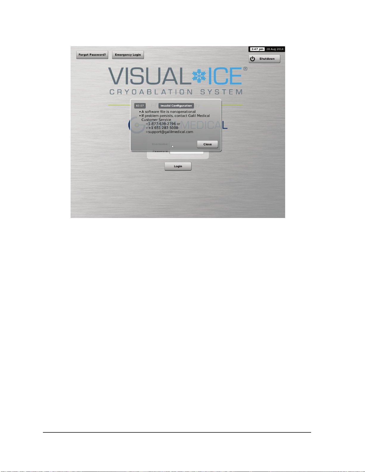
Screen 7-2. Invalid Conguration Message
5. If updating the software to a newer version available on a USB ash drive.
• Login as an administrative user.
• Press the Congure Settings button on Startup Screen (Screen 3-2).
• Press the Manual Software Update button on the Congure Settings Screen (Screen 3-15).
• Insert the USB ash drive.
NOTE: Wait 20 seconds for the system to recognize the ash drive.
• Press the Browse button.
• Select the le to conduct the upgrade.
• Press the Update button.
NOTE:
o Wait until a displayed message conrms completion of the update.
o The upgrade may take half an hour to complete.
7-2 User Manual
Page 85

7.2 Electronics, Electrical and User Error Related Issues
Symptom Potential Causes / Solutions
System does not turn ON (i.e., the
fan is not running) or power is lost
during procedure
Channel or needle is not
recognized by the system and not
available for use
Touch screen does not respond 1. The track pad may be used to control the system.
USB ash drive is not functioning
Or
The USB ash drive is not
recognized by the system
1. The power control knob on the front panel of the system
or power switch on the rear panel is OFF (Figure 2-1
and Figure 2-2). Turn the power ON.
2. The power cable to the Visual-ICE System is
disconnected from the power outlet or from the rear
panel of the system. Connect the power cable to the
Visual-ICE System, checking that the power cable is fully
seated. Connect the power cable to the power outlet.
3. There is no power at the wall outlet. Ensure the power
outlet is switched ON. Call the hospital Biomedical
Engineer for assistance, if needed.
4. A fuse may have blown. Spare fuses are located in the
power cord inlet on the system (Figure 2-2). Reference
Section 7.2.1 for instructions on how to replace fuses in
the system.
1. Check the corresponding Channel Locking Bar and
ensure it is fully in the locked position.
2. At least one needle must be inserted into a channel for
the channel to be available for use.
3. If a needle with a memory chip is being used and steps
1 - 2 are unsuccessful, select a new needle for use.
Contact Galil Medical Customer Service to arrange
return of the non-operational needle.
4. The channel may be defective. Do not use this channel.
Move the needle(s) to a dierent channel. Conduct the
Needle Integrity and Functionality Test again.
2. The touch screen may be out of calibration. Navigate to
the Congure Settings screen using the track pad and
re-calibrate the touch screen.
3. Turn OFF and restart the system using the power control
knob on the front of the system (Figure 2-1).
1. The USB ash drive is not connected to the proper USB
port. Connect the USB ash drive to the port with the
USB port icon (Figure 2-3).
2. The USB ash drive is not properly connected to USB
port. Remove the USB ash drive from the designated
USB port on the system. Wait a few seconds and
reconnect the USB ash drive to the designated USB
port.
3. If the problem persists, try using a dierent Galil Medical
supplied USB ash drive.
4. The USB ash drive is faulty. Replace the USB ash
drive with a new Galil Medical supplied USB ash drive.
Visual-ICE™ Cryoablation System
7-3
Page 86
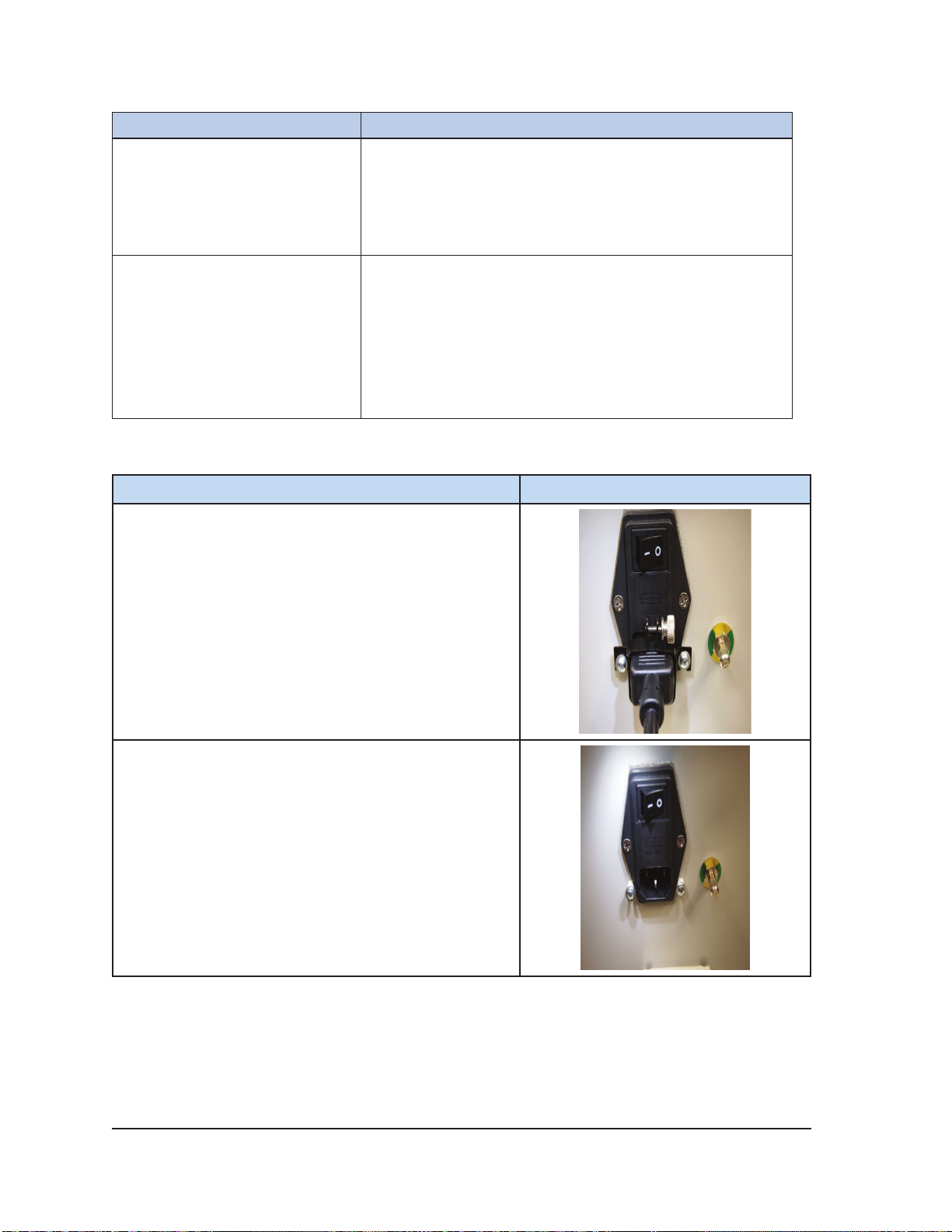
Symptom Potential Causes / Solutions
The Login Screen appeared
after the system was left idle for
more than 2 hours while on the
Procedure Screen
Touch Screen goes blank during a
procedure
7.2.1 Replacing Fuses
Instruction
Enter the appropriate password to return to the Procedure
Screen.
The video cable may be disconnected.
WARNING. Do not touch the screen if the touch-screen
monitor goes blank for greater than ve (5) seconds
during a procedure. Immediately turn o power to the
system and end the procedure to avoid inadvertent
activation of needles.
Contact Galil Medical Customer Service.
Photo
1. Turn the Power Switch OFF on the rear of the VisualICE System. Loosen the thumb screw on the cord
retention clip.
2. Remove the power cord from the retention clip.
Remove the two screws that secure the retention clip
and remove the retention clip from the power inlet.
7-4 User Manual
Page 87
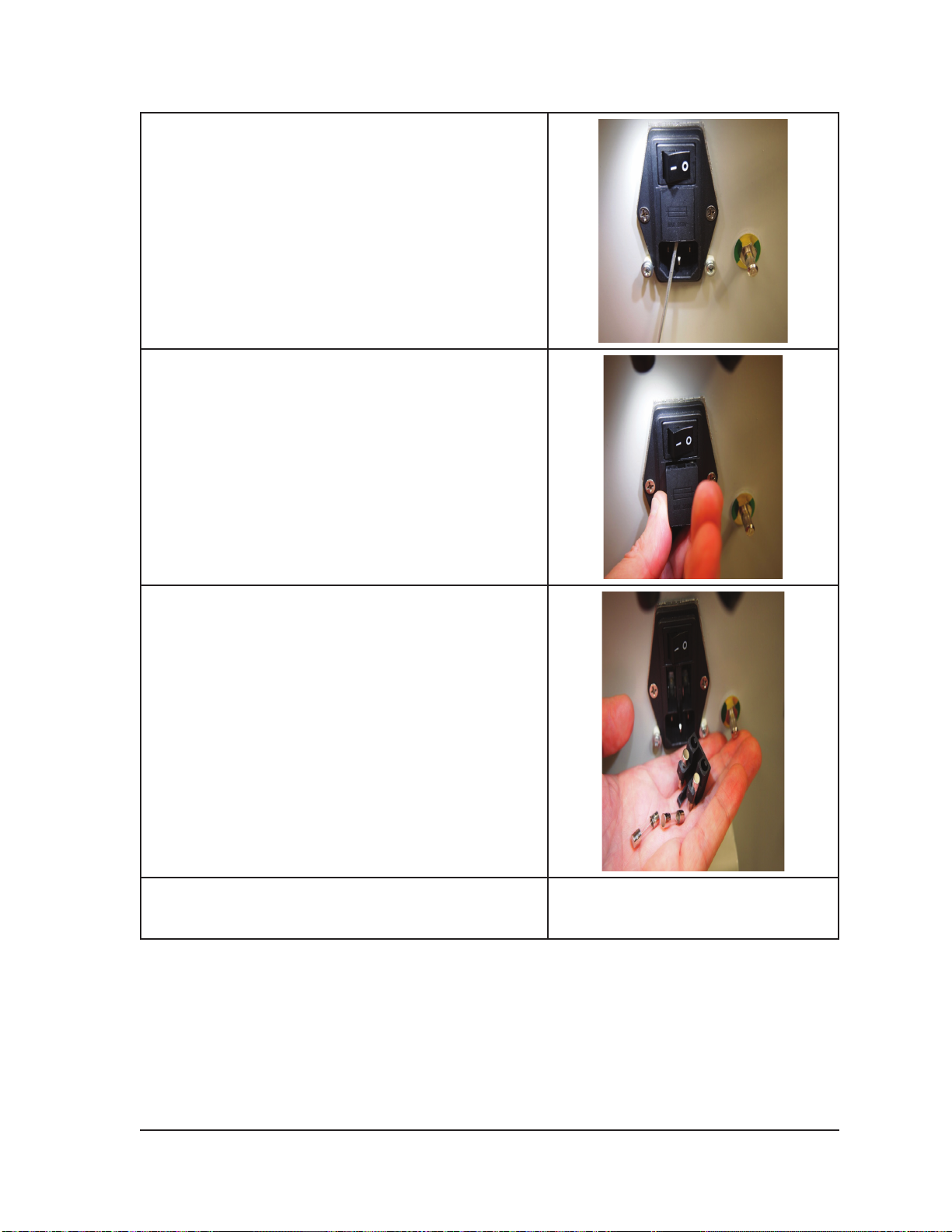
3. Insert a small screwdriver into the slot on the bottom
of the fuse holder to begin to snap the fuse holder
out of the power inlet.
4. While holding your hand under the fuse holder,
carefully slide the fuse holder out of the power inlet.
There are four fuses in the fuse holder.
5. Catch the fuse holder and fuses as the fuse holder
is removed from the power inlet. The two fuses that
remain in the fuse holder are the fuses that are part
of the system circuit.
6. Replace the fuses in the fuse holder with the
two loose fuses. NOTE: Use only Galil Medical
specied fuses in the Visual-ICE System.
Visual-ICE™ Cryoablation System
7-5
Page 88
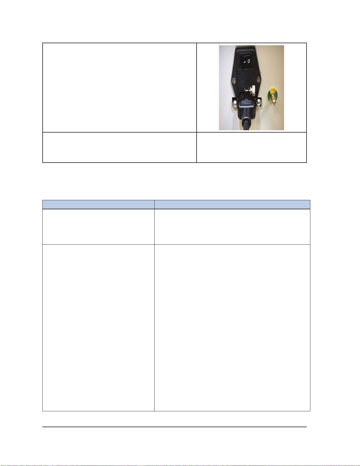
7. Snap the fuse holder back into the power inlet.
Replace the retention clip, plug in the power cord,
and tighten the thumb screw on the retention clip.
8. Call Galil Medical Customer Service to schedule
a service call to determine the cause of the blown
fuses, to determine if service is required and to
provide replacement fuses.
7.3 Gas Issues
Symptom Potential Causes / Solutions
The Visual-ICE System does not allow
testing of a needle in a locked channel
Needle is not freezing during the Needle
Integrity and Functionality Test
The Argon Shuto Valve may be in the GAS OFF position.
Verify that the Argon Shuto Valve (Figure 2-2) is in the
GAS ON position to allow sucient gas ow.
Verify that the gas cylinder valve is fully open.
1. The argon gas cylinder valve may be closed. Open
the gas cylinder valve by turning the gas cylinder
valve counter-clockwise to allow sucient gas ow.
Verify that appropriate pressure is displayed on the
Gas Indicator.
2. Conrm that the argon gas cylinder is connected to
the argon inlet.
3. The needle may be clogged. Try to test it again.
4. If the needle still does not freeze,
• Press the Stop button to stop all activity on the
• Hold the needle connector rmly with one hand
• Move the needle to a dierent channel and run
NOTE: If only one needle is connected to the
channel, there may be some residual pressure behind
the needle connector.
channel.
and unlock the channel to disconnect the needle.
the test again.
5. If the problem persists, replace the needle with a new
needle.
7-6 User Manual
Page 89

Symptom Potential Causes / Solutions
No helium gas is delivered to the needle 1. The helium gas cylinder valve may be closed.
Open the gas cylinder valve by turning the valve
counter-clockwise to allow sucient gas ow. Verify
that appropriate pressure is displayed on the Gas
Indicator.
2. The needle may be clogged.
• Press the Stop button to stop all activity on the
channel.
• Hold the needle connector rmly with one hand
and unlock the channel to disconnect the needle.
• Move the needle to a dierent channel and run
the test again.
NOTE: If only one needle is connected to the system,
there may be some residual pressure behind the
needle connector.
3. If the problem persists, replace the needle with a new
needle.
The Manual Vent Valve is leaking gas The Manual Vent Valve may be open. Fully close the
Manual Vent Valve.
There is a hissing sound before the
needles are connected
The pressure displayed on the Gas
Indicator indicates the gas pressure is
too low (Table 4-2)
1. Check that the regulated pressures are within the
working pressure limits (green range on the Gas
Indicator display). The system may be venting to
reduce the pressure to below 4200 psi to prevent
damage to the system. If the pressure drops to within
working pressure range, the system will operate
normally.
2. The Automatic Vent Valve may be stuck open. If the
manual vent valve is fully closed and the hissing
persists, shut down the system and contact Galil
Medical Customer Service.
1. Verify the Argon Shuto Valve is open.
2. Verify that the gas cylinder valve is suciently opened
to allow gas ow. If necessary, open the valve
approximately another half turn.
3. Verify that the cylinder contains sucient pressure
using the gauge on the cylinder.
4. Replace the cylinder, if needed.
Visual-ICE™ Cryoablation System
7-7
Page 90

Symptom Potential Causes / Solutions
During the Needle Integrity and
Functionality Test, the needle is freezing
in the rst 45 sec of the test instead of
thawing, and then starts thawing for 15
sec instead of freezing
The gases are connected incorrectly (e.g., the helium gas
supply line is connected to the argon cylinder and vice
versa).
• End the procedure.
• Vent the high pressure gas from the system.
• Disconnect the gas supply lines and re-connect
them to the correct cylinder.
• Start a new procedure.
• Run the needle test again.
It is very dicult to loosen the pressure
gauge connected to the cylinder, or you
cannot disconnect the argon/helium
gas supply lines from the gas inlet
connections
Gas begins leaking through a needle
port after gas ow was started using the
Test, Freeze or Thaw buttons
The gas lines were not vented and the gas lines are still
under pressure.
WARNING. Do not apply excessive force to release
the gas supply lines or to loosen the pressure gauge.
The gas lines may still be under pressure.
• Verify that the gas cylinders are CLOSED.
• Verify the pressure gauge at the gas cylinder is 0.
• If in the Procedure Screen, verify the gas
pressure display shows no gas connected.
• If the Visual-ICE System is ON, end the
procedure and vent the system using the
automatic vent function.
• If still unable to disconnect the gas supply lines,
or if the system is OFF, open the Manual Vent
Valve on the rear of the system to completely vent
the system.
• Upon completion, close the Manual Vent Valve.
The channel may have a loose or broken socket.
Disconnect the needle and move the needle to a dierent
channel. Conduct the Needle Integrity and Functionality
Test again on the needle.
Contact Galil Medical Customer Service.
7-8 User Manual
Page 91
7.4 Mechanical Issues
Symptom Potential Causes / Solutions
Needle cannot be rmly connected
in the needle port
Locking bar on the Needle
Connection Panel cannot be
positioned in the LOCKED position
Console does not move freely 1. Release the brake to unlock the front wheels.
1. Verify that the locking bar is in the UNLOCKED position.
2. Needle connector may be defective. Use a dierent
needle.
3. Residual gas pressure may be in the needle port. Use a
dierent channel.
4. Check the Gas Indicator display. If there is pressure in
the system, end the procedure and vent the system using
the automatic vent function.
1. Verify that all needles in the channel are fully inserted in
the needle connection ports.
2. The Locking Bar may be defective. Move the needle to a
dierent channel. Contact Galil Medical customer service
to schedule a service call.
3. Check the Gas Indicator display and verify the system is
not pressurized. If there is pressure in the system, end
the procedure and vent the system using the automatic
vent function.
2. Check the individual rear wheel brakes and ensure the
brakes are released.
7.5 Gas Cylinders and Gas Supply Lines
Symptom Potential Causes / Solutions
Safety cable is missing at either the
cylinder side or the system side of
the gas supply line
A gauge or a gas supply line is
damaged
A gas leak was detected between
the gauge adapter and the cylinder
main valve
Do not use a gas supply line with a missing safety cable.
Doing so could compromise the safety of personnel in the
room. Contact Galil Medical Customer Service.
Do not use any damaged product. Contact Galil Medical
Customer Service for new accessories.
• Tighten the connection using the wrench provided with
the Visual-ICE System.
• Close the cylinder valve and vent the gas from the
Visual-ICE System and the gas supply lines using the
Manual Vent Valve (Figure 4-1). Verify the system is
depressurized. Loosen and remove the gauge assembly
adapter. Verify no debris is on the gas cylinder connection
point; clean the sealing surface as needed to remove
any debris. Reposition and tighten the gauge assembly
adapter onto the cylinder valve, using the wrench
provided with the Visual-ICE System.
Visual-ICE™ Cryoablation System
7-9
Page 92

7.6 Needles
Symptom Potential Causes / Solutions
A needle with a memory chip is not
recognized by the system
During the freeze phase or
following a thaw phase, no iceball
forms on the needle(s) in a given
channel
Only some of the temperature
sensor locations on the MTS
needle are registered on the
Temperature Sensors display
MTS needle is connected but
temperature is not registered on the
Temperature Sensors display
During the Needle Integrity and
Functionality test bubbles are seen
escaping from the needle
Needle was bent or damaged while
attempting to unpack or use it
1. Move the needle to a dierent port.
2. If the system still does not recognize the needle, select
the needle type from the drop-down menu displayed by
the system.
3. If the needle is still not recognized, check the system's
software version. (The software version is displayed on
the Startup Screen). Contact Galil Medical customer
service.
1. Perform the following steps in the order in which they are
described:
• Stop freezing/thawing actions for all channels.
• Thaw the problematic needle(s) for at least one
minute.
• Freeze the needle(s) to verify proper function.
2. If the problem persists, connect a new needle into a
dierent channel and test the needle. Continue the
procedure with the newly tested needle.
1. Move the MTS needle to a dierent port.
2. Replace the MTS needle.
3. Contact Galil Medical Customer Service.
1. Move the MTS needle to a dierent port.
2. Replace the MTS needle.
3. Contact Galil Medical Customer Service.
WARNING. Do not use the needle.
• Disconnect the needle from the Visual-ICE System
and segregate the needle.
• Return the needle to Galil Medical for evaluation.
• Use a new needle.
• Test the new needle to conrm the integrity and
functionality of the new needle.
• Contact Galil Medical Customer Service for further
instructions upon completion of the procedure.
WARNING. Do not use the needle.
• Segregate the needle.
• Use a dierent needle to continue the procedure.
• Contact Galil Medical customer service for further
instructions upon completion of the procedure.
7-10 User Manual
Page 93
7.7 Displayed Messages
The Visual-ICE System displays a message on the User Interface screen when a user requests
assistance or when user, needle or system errors are detected.
NOTE: Record and report the message number (e.g., 10-01, 80-02) if assistance is required from
Galil Medical Customer Service.
Message Reason for Appearance
LOGIN
10-01 Login
• You have not entered the correct Login Name
• Reenter your Login Name
• Contact your System Administrator if assistance is
required
• Contact Galil Medical Customer Service if further
assistance is required
o +1 877 639 2796 or
o +1 651 287 5000
No name was entered.
OR
The name entered didn’t match assigned
names in the system.
10-02 Login
• You have not entered the correct Password
• Reenter your Password
• Contact your System Administrator if assistance is
required
• Contact Galil Medical Customer Service if further
assistance is required
o +1 877 639 2796 or
o +1 651 287 5000
No password was entered.
OR
The password entered didn’t match
the password associated with the login
name.
Visual-ICE™ Cryoablation System
7-11
Page 94

Message Reason for Appearance
10-03 Reset Password Challenge
• To reset your password, contact Galil Medical
Customer Service
o +1 877 639 2796 or
o +1 651 287 5000
• Relay the Challenge on the screen below
• Enter the Response provided by Customer Service
• Press the Reset button
User forgot their password, pressed the
Forgot Password button and received
a challenge to be relayed to Customer
Service.
10-04 Password Reset
• Your password has been reset to XXX
• Change your password in the conguration screen
when convenient
10-05 Emergency Login
• To obtain an emergency login, contact Galil Medical
Customer Service
o +1 877 639 2796 or
o +1 651 287 5000
• Relay the Challenge on the screen below
• Enter the Response provided by Customer Service
• Press the Login button
User correctly entered the reset
password challenge and received a
temporary password.
User requested an emergency login and
received a challenge to be relayed to
Customer Service.
7-12 User Manual
Page 95

Message Reason for Appearance
10-06 Incorrect Response
• You have not entered the correct response
• Contact Galil Medical Customer Service for a
Response to the on screen Challenge
o +1 877 639 2796 or
o +1 651 287 5000
10-07 Incorrect Response
User tried to access the Emergency
Login and did not respond correctly
to the challenge. User must contact
Customer Service in order to receive an
emergency login response. This action
does not reset a password.
• You have not entered the correct response
• Contact Galil Medical Customer Service for a
Response to the on screen Challenge
o +1 877 639 2796 or
o +1 651 287 5000
PROCEDURE
20-01 Cannot Start Test
• The gas pressure is too low to begin a procedure
• Check that the gas cylinders have enough pressure
to start the procedure
20-02 Argon Shut O Valve
• The argon shut o valve may be closed
• Check and open if necessary
User tried to reset their password
and did not respond correctly to the
challenge. User must contact Customer
Service in order to reset their password.
User pressed the Test button when
either gas cylinders were not yet
connected or the gas pressure is below
operating pressure. To proceed, gas
cylinders with sucient pressure must
be connected.
At system start-up, the system detected
gas connected, but no gas was entering
the system. The argon shut o valve
may be closed. To proceed, the argon
shut o valve must be open.
Visual-ICE™ Cryoablation System
7-13
Page 96

Message Reason for Appearance
20-03 Test All
• You selected to control all needles simultaneously
• Do you want to initiate test in all needles now?
YES NO
20-04 Freeze All Channels
User selected Test button in ALL
channel to control all active channels.
To proceed, the user must conrm test
for all connected needles.
• You selected to control all needles simultaneously
• Do you want to initiate [x%] freeze for all active
needles now?
YES NO
20-05 Freeze All Intensity
• You selected to control all needles simultaneously.
• Do you want [x%] freeze intensity applied to all
needles now?
YES NO
User selected Freeze button in ALL
channel to control all active channels. To
proceed, the user must conrm freezing
of all active needles.
User selected a freeze intensity in ALL
channel to control all active channels.
To proceed, the user must conrm the
selected intensity is to be applied to all
active needles.
7-14 User Manual
Page 97

Message Reason for Appearance
20-06 Thaw All Channels
• You selected to control all needles simultaneously
• Do you want to initiate thaw for all active needles
now?
YES NO
20-07 Stop All Channels
• You selected to control all needles simultaneously
• Do you want to stop activity in all needles now?
YES NO
20-10 Cautery
User selected Thaw button in ALL
channel to control all active channels. To
proceed, the user must conrm thawing
of all active needles.
User selected Stop button in ALL
channel to control all active channels.
To proceed, the user must conrm stop
for all active needles.
• CAUTION: Activation of thermal cautery immediately
ceases all other cryoablation operations for the
duration of cautery activity
• Do you want to proceed with cautery?
YES NO
20-11 End Procedure
• Are you sure you want to end the procedure?
YES NO
Visual-ICE™ Cryoablation System
User pressed Thaw button to open
the Advanced Thaw Controls and the
thermal cautery option. The CAUTION is
displayed upon user selecting advanced
option for thermal cautery.
User selected End Procedure and must
conrm desire to end the procedure.
7-15
Page 98

Message Reason for Appearance
20-12 Automatic Vent
• Do you want to automatically vent high pressure gas
from the system?
YES NO
20-13 Automatic Vent
• Is the gas supply closed?
YES NO
20-14 Automatic Vent
• The gas pressure is not dropping
• Check that the gas cylinder shut o valve is closed
User was provided an option for
automatically venting the high pressure
gas in the system.
If user selected the option for automatic
gas venting, the user will need to
conrm the gas supply is closed before
automatic venting is activated.
User selected to automatically vent high
pressure gas at the end of a procedure,
but the pressure was not dropping. User
must ensure the shut o valve is closed.
20-15 Automatic Vent
User selected to automatically vent
• Venting is in progress
• If needles are still connected, do not unlock channels
or disconnect needles until venting is completed
20-16 Automatic Vent
• Automatic venting successfully completed
7-16 User Manual
the high pressure gas at the end of the
procedure.
User chose to automatically vent the
high pressure gas at the end of the
procedure.
Page 99

Message Reason for Appearance
20-17 Gas Vent
• Before disconnecting the gas hose, manually vent
the Visual-ICE System using the Manual Vent Valve
on the rear of the machine
20-18 System Shutdown
User selected to not use the feature to
automatically vent high pressure gas
from the System.
• Do you want to shut down the system?
YES NO
20-19 Procedure Timeout
• The procedure has exceeded the allowable time
• Procedure will be terminated
20-20 Maximum Activity for FastThaw
• Maximum limit for FastThaw reached
• Wait until thawing is complete before activating
additional FastThaw needles
• This channel will use passive thaw
User selected Shutdown in the login
screen to power down the system.
The procedure exceeded the allowable 8
hour duration.
User attempted to activate more than
four FastThaw needles. The Visual-ICE
System supports simultaneous operation
of no more than four FastThaw needles.
After completing the thaw phase with
four needles, additional needles may be
activated for FastThaw.
20-21 Maximum Activity for i-Thaw
• Maximum limit for i-Thaw reached
• Wait until thawing is complete before activating
additional i-Thaw needles
• This channel will use passive thaw
Visual-ICE™ Cryoablation System
Thawing with i-Thaw is limited to a
maximum of 9 needles simultaneously
activated in thaw mode.
When thawing with CX-type needles,
thawing is limited to a maximum of 7
needles simultaneously activated.
After completing the thaw phase,
additional needles may be activated..
7-17
Page 100

Message Reason for Appearance
20-22 Maximum Activity for Active Thaw
• Maximum limit for i-Thaw and FastThaw reached
• Wait until thawing is complete before activating thaw
on additional needles
20-23 Maximum Activity for Test
• Maximum limit for test reached
• Wait until testing is complete before activating
additional needles for testing
20-24 Advanced Thaw Unavailable
• Needle(s) in channel X are not capable of advanced
thaw
• Advanced thaw activity is unavailable
User attempted to activate more needles
than are supported for active thaw. After
completing the thaw phase, additional
needles may be activated.
User attempted to initiate testing on
more needles than are supported for
simultaneous testing.
User attempted to initiate Advanced
Thaw in a channel. The channel did not
contain i-Thaw or FastThaw capable
needles.
20-25 Advanced Thaw Unavailable
• Advanced thaw activity is unavailable on channel X
while helium is connected
• Use helium thaw or disconnect helium
GAS
30-01 Gas Vent
• Gas was not appropriately vented from the Visual-
ICE System when the system was last used
• Vent the system, using either the automatic vent
option or the Manual Vent Valve
User attempted to initiate Advanced
Thaw while helium was connected. If
helium is connected, the system defaults
to helium thaw mode. If mixed needle
types are connected (some helium thaw
and some i-Thaw), the system also
defaults to helium thaw mode.
Upon startup, there was gas pressure
remaining in the system which will make
it dicult to connect needles.
7-18 User Manual
 Loading...