

Page 1
OWNER’S MANUAL
BTPAINTBALL.COM
Page 2

BTPAINTBALL.COM
CONTENTS
1. Rules for Safe Marker Handling 1
2. Introduction and Specifications 1
3. Battery Replacement and Life Indicator 2
4. Compressed Air/Nitrogen Supply 2
5. Basic Operation 3
6. Firing the TM-7 4
7. Break-Beam Eyes Operation 4
8. Unloading the TM-7 5
9. Regulator and Velocity Adjustments 5
10. Programming 6
11. Setting Functions 7
12. Trigger Adjustments 9
13. General Maintenance 10
14. Assembly/Disassembly Instructions 10
15. Storage and Transportation 13
16. Troubleshooting Guide 14
17. Diagram and Parts List 17
18. Warranty Information 20
©2008 BT Paintball Designs, Inc. The BT Shield,
“Battle Tested” and “TM-7” are trademarks of
BT Paintball Designs, Inc. All rights reserved.
Page 3
BTPAINTBALL.COM
2
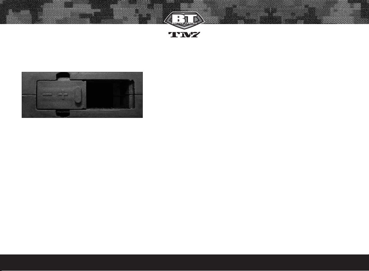
3. Battery Replacement and Life Indicator
The TM-7 requires a single 9-volt battery as the electronic power source.
The use of long life batteries is recommended. The battery is installed by
sliding the battery door open and replacing the 9 volt battery.
The TM-7 also has a Battery Life indicator. If in standard operation and the
LED flashes with a Green color then the battery is good, if the LED is
Orange the battery is fairly depleted and you should change battery soon,
or if the LED is Red then the battery should be replaced immediately.
Notes:
• Make sure you follow the polarity marking on the battery door.
• Some rechargeable batteries might be too large for the TM-7 battery
compartment. If they do not fit, please do not force them as this may
damage the TM-7.
4. Compressed Air/Nitrogen Supply
The TM-7 is designed to work with Compressed Air/Nitrogen Only. Do
Not use CO2, as it will damage your TM-7
Consult the place where you purchased your TM-7, or a recognized and
competent air smith, for instruction in the safe handling of compressedair cylinders before purchasing or connecting one to your TM-7.
The TM-7 utilizes a fully functional regulator at the bottom of the grip
frame that doubles as an ASA (Air Source Adapter) or Receiver for a standard threaded pre-set output compressed air system. It is strongly recommended that a very high-flow “low pressure” (350-450 psi) fixed-output system is utilized as an air source for your TM-7. Using a “high pressure” output compressed air tank is acceptable. If you are using an adjustable output regulator system, the output pressure should be between 350-450 psi.
Before pressurizing your TM-7:
• Check to make sure that you and anyone within range are wearing eye
protection designed specifically for paintball.
• Double check that all screws are tightened and no parts are loose
before installing your tank.
• Ensure you have a barrel plug, barrel sock or other specifically designed
barrel-blocking device in place.
• Make sure there are no paintballs in the marker.
• The Power should be OFF and the Selector switch should be set to the
Safety position.
Air can now be applied, the marker will become pressurized.
Notes:
• Remember compressed air or nitrogen systems can be extremely dangerous if misused or improperly handled. Use only cylinders meeting
D.O.T. or regionally defined specifications.
• Never disassemble your tank or tank regulator. Only a qualified and
trained technician should perform work on your tank and tank regulator.
• Never add any lubricants or greases into the fill adapter on your tank
regulator or into the TM-7 regulator.
Page 4
BTPAINTBALL.COM
3
5. Basic Operation
Safety and safe marker handling are the most important aspects of paintball sports. Please practice each of the following steps with an unloaded
marker before attempting to charge your marker with compressed air
and paintballs.
• Do not install compressed air or load paintballs into your TM-7 until you
feel completely confident with your ability to handle your TM-7 safely.
• Keep your finger out of the trigger guard and away from the trigger;
point the muzzle of the marker in a safe direction at all times. Keep the
marker turned OFF until ready to operate. The TM-7 uses an ON/OFF
switch and a selector switch for its safety devices.
• Always keep your TM-7 pointed in a safe direction. Always use a barrel
plug or barrel blocking device. Always use ASTM approved paintball
specific eye protection in any areas where paintball markers may be discharged. Remember that the ultimate safety device is you, the operator.
Barrel Installation
Make sure marker is degassed, hopper removed, no paintballs in the feed
elbow or breech and the TM-7 is turned off.
• While pointing marker in a safe direction, place the threaded end of the
barrel into the front opening of the marker body.
• Turn the barrel clockwise until it stops (do not over tighten).
• Install a barrel blocking device. This can be a barrel plug or other such
device that prevents the accidental discharge of a paintball.
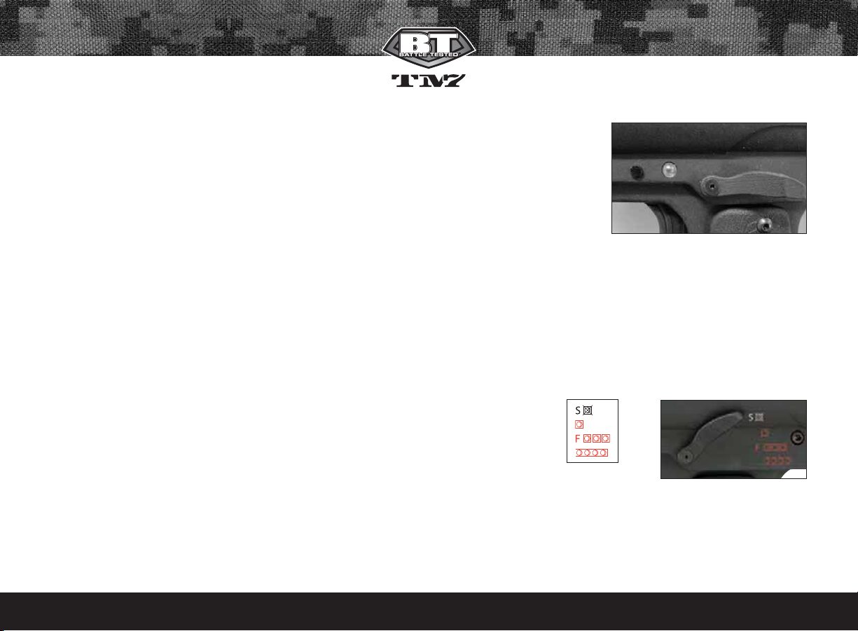
Switching On your TM-7
To switch the TM-7 ON, set the Selector Switch to the Safety position.
Locate the Power Button on the left side of the marker. Push and hold the
button for 2 seconds and the LED light will turn Green and then to Red.
Release button and the LED
will remain RED.
The TM-7 will now be ON and
in the Safety Position. To make
the TM-7 Live, move the
Selector Switch to the desired
Firing Mode.
Switching OFF your TM-7
Move the Selector Switch to the Safety Position, push and hold the Power
Button for 2 seconds and the LED will turn from Red to Green. Release
button and the TM-7 will switch OFF.
Selector Switch
The TM-7 comes equipped with a 4 position Selector switch. The TM-7
comes factory set in the recreational firing mode setting. Simply move the
selector from Position (0) Safety, to Positions (1-3) to change to a Firing Mode.
Selector Positions
0 = Safety -----------------------1 = Semi Auto --------------2 = 3 NXL Full Auto -----
3 = PSP Burst ------------------
Automatic OFF feature
The TM-7 also has an “Automatic OFF” feature. If you accidentally leave
your TM-7 powered up, it will shut itself OFF after approximately 1 hour
of inactivity.
Page 5
BTPAINTBALL.COM
4
Eye Function
The TM-7 board is pre-programmed to activate the eye system each time
the marker is powered up. See Section 7 (Break beam Eyes Operation) for
more details.
Installing a Loader and Paintballs
The TM-7 comes equipped to accept 1.03" (outer dimension) standardgravity feed loaders as well as most agitating and force-feed loaders. Fit
the loader directly into the feed elbow. It might be necessary to adjust the
feed elbow pinch bolt to your loader.
The TM-7 uses .68 Caliber, water-soluble paintballs, readily available at
paintball pro-shops, commercial playing fields, and many sporting goods
stores. The paintballs are feed from the loader through the feed elbow
and into the breech of the marker.
Notes:
• The shell of TM-7 is designed so you
can install the Empire Magna
transmitter kit.
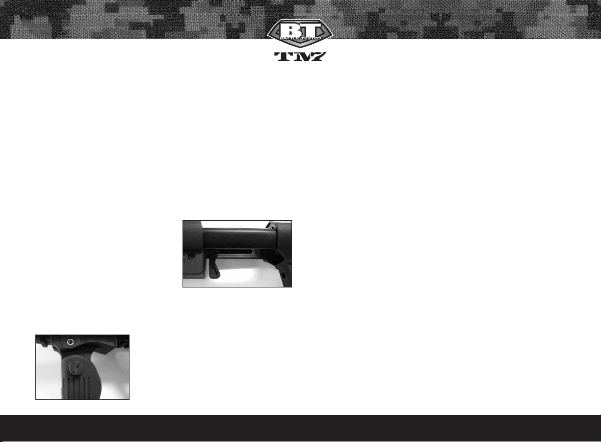
Stock Adjustment
The TM-7 Stock can be adjusted by pushing the stock adjustment lever to
the left. Adjust the stocks length by pulling or pushing on the back of the
stock. Make sure the lever springs back to the right to lock it in position.
Foregrip Adjustment
The TM-7 foregrip can be adjusted in two
ways.
• To slide the foregrip, remove the foregrip
retention screw and then slide it to the
desired position and then reinstall and
tighten the retention screw.
• To tilt the foregrip back simply press the tilt button located on the left
side of the foregrip.
6. Firing the TM-7
Keep your finger out of the trigger guard and away from the trigger, point
the barrel of your marker in a safe direction at all times during this
process. Be sure your goggles are securely in place and make sure the
TM-7 marker is OFF. Push the Power button and hold for 2 seconds until
the LED light changes from Green to Red
Warning: Always keep your TM-7 pointed in a safe direction! Everyone
within firing range should always use paintball approved eye and face
protection in the presence of live paintball markers.
• Place the empty loader onto the marker.
• Be sure that it is securely mounted in place.
• Apply the compressed gas, pressurizing the marker.
• Put the paintballs into the loader.
• Remove the barrel plug, sock or barrel-blocking device.
• Aim the TM-7 in a safe direction.
• Turn the TM-7 ON.
• Move the selector switch to the desired firing mode.
• Aim the TM-7 at the target.
• Place your finger on the trigger.
• Pull the trigger with a smooth squeezing motion.
7. Break beam Eyes Operation
The TM-7 uses a break beam eye system to determine the absence or
presence of a ball for the purposes of reduced paint breakage and optimum rates of fire. The TM-7 board is pre-programmed to activate the eye
system each time the marker is powered up.
Page 6

BTPAINTBALL.COM
5
To turn the eyes OFF, ensure that there are no paintballs in the TM-7
breech or feed elbow, make sure the marker is switched OFF, and while
pulling and holding the trigger, turn the marker ON. A quick double blinking Green LED will indicate that the eye system has been deactivated.
To turn the eyes back ON, simply tap the power button one time quickly.
Notes:
• A slow consistent single flashing Green LED indicates that the eyes are
ON with no ball in the breech and a rapid flashing Green LED indicates
that there is a ball in the breech.
• For optimal performance of the TM-7 eyes, keep the inside of the TM-7
breech clean and clear of broken paint, paint residue, or other debris.
• Although the eyes can be cleaned via cleaning the breech of the TM-7
marker, if the eyes need to be accessed please follow the steps outlined
in the Disassembly/ Assembly section of this manual.
8. Unloading the TM-7
Always keep your TM-7 pointed in a safe direction and always keep your
protective eye, face and ear wear on until marker is completely unloaded.
• Be sure your finger is away from the trigger area.
• Place the barrel plug, sock, or barrel blocking device into the end of the barrel.
• Move the Selector switch to the safety position (0).
• Turn the TM-7 OFF by pressing and holding the Power button. The LED
will turn from RED to GREEN. Observe the light to make sure it is no
longer lit.
• Remove your pressurized gas source by slowly and carefully unscrewing it.
• If you are using an electronic loader make sure loader is completely
turned OFF.
• Slightly tilt the marker so that the loader is lower than the body.
• Remove the loader by spinning it in a clockwise direction and gently
pulling it.
• Read the pressure gauge and make sure the pressure reads 0 PSI.
• DO NOT look down the barrel but look down the feed neck to make
sure there are no paintballs in the breech.
•Remove the barrel from the marker.
• Make sure there are no more paintballs remaining in the barrel.
Note: Always keep your TM-7 pointed in a safe direction!
9. TM-7 Regulator and Velocity Adjustment
The TM-7 utilizes a fully functional TM-7 Bottom-line Regulator at the bottom of the grip frame that doubles as an ASA Adapter/Receiver for a
standard threaded pre-set output compressed air systems. This unique
regulator system channels air through the air transfer tube, eliminating
the need for external macro line and fittings. The TM-7 Bottom-line
Regulator controls the amount of air pressure going from your compressed air system into the maker itself.
The TM-7 regulator should be factory pre-set at 200 PSI as this is the best
operating pressure for firing the marker. However, if over time you do
need to adjust the pressure only use the Regulator Adjuster Screw on the
front of your TM-7 Bottom-line Regulator.
Page 7
BTPAINTBALL.COM
6
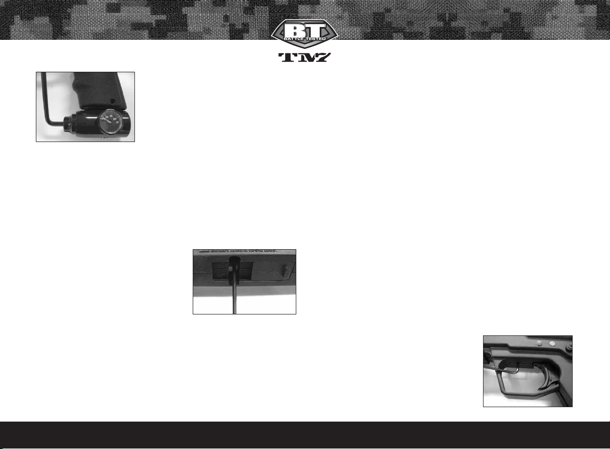
Regulator Adjustment
If adjustments are needed use a 3/16"
Allen key and insert it into the regulator
adjustment screw. This is located in the
front of the regulator.
To Increase Output Pressure- Turn the
regulator’s adjustment screw clockwise.
To Decrease Output Pressure- Turn the regulator’s adjustment screw
counter-clockwise.
Notes:
• Always watch the gauge as you are adjusting the pressure.
• The Bottom-line regulator should not be disassembled.
• Never set the regulator above 200 psi.
Adjusting Velocity
At the back of the TM-7 main body is the
Bolt Guide Cap. The holes in the bolt
guide cap serve as your velocity adjuster.
Confirm that the pressure on your TM-7
Bottom-line Regulator is at 200 PSI. You
can access the velocity adjuster thru the
bottom of the shell, just in front of the
battery door .Then you can increase or decrease the velocity on your
TM-7 by tightening or loosening the velocity adjustment screw, with a
7/64" inch Allen wrench.
To Increase Velocity- Unscrew or loosen the velocity adjustment screw by
turning it toward the left side of the marker (counter clockwise). Rotate the
velocity adjustment screw counter-clockwise in small increments, stopping between slight turns to test velocity, until desired velocity is achieved.
Do not back the adjuster out too far. Stop if you hear an air leak, and
adjust back in a 1/4 turn. A paintball specific radar chronograph should
be used to accurately measure your velocity.
To Decrease Velocity- tighten or screw-in the velocity adjustment screw by
turning it toward the right side of the body (clockwise). Rotate the velocity
adjustment screw clockwise in small increments (1/4 turn or less), stopping between slight turns to test velocity, until desired velocity is achieved.
A paintball specific radar chronograph should be used to accurately
measure your velocity.
Notes:
• This marker was designed with safety and safety standards in mind. If
you attempt to shoot paintballs at a higher velocity than established
safety standards, the marker may not function properly.
• This marker is not designed to shoot above the safety limits established
by industry standards but under certain conditions it may. It is therefore
important to check the velocity each time before playing with your TM-7.
10. Programming
Note: In this section, you will see the phrase "Cycle the Selector Switch".
To Cycle the Selector Switch, move the Selector Switch from Position (0) to
Position (3) and then back to Position (0), stopping briefly at each middle
position to observe the color change of the LED.
Tournament Lock On/OFF
The TM-7 comes with a Tournament Lock
which will lock your TM-7 into the firing mode
currently selected. The Tournament lock button is accessed thru a small hole at the top of
the trigger. The TM-7 must be turned OFF to
change the Tournament Lock setting. Use a
Page 8
small Allen wrench and gently press the tournament lock button, and the LED
will blink to show the current status. If the LED blinks RED, the tournament lock
is currently OFF. If the LED blinks GREEN, the tournament lock is currently ON.
To change the tournament status, press the button once to display the status,
then press again within 1 second and the LED will blink the new status.
To Enter Programming Mode- The TM-7 must be OFF and the tournament lock must be OFF to begin managing the functions. While the TM7 is OFF, with the selector switch in the “0” position, press and hold the
Power Button, cycle the Selector Switch, then release the Power Button to
enter programming mode. If done correctly the LED will change to a Solid
RED, which is the Firing Mode Function.
Once in programming mode, with selector switch in the "0" position, each
time the Power Button is pushed you will cycle to the next Function and the
LED will change to a specific color per the descriptions below.
Function’s current value- To view a Function’s current value, cycle to the
Function using the power button, then simply pull the trigger once, and
observe the number of flashes.
Changing a Function’s Value- Once you have selected the Function you wish to
change, move the Selector Switch to Position (1) or (2) to change the value up or
down, then each time the Trigger is pulled it will Increase or Decrease the
Function value by 1. If the Selector Switch is in Position (3), a single trigger pull will
return a Function value to its default setting. Once the value is changed, move
the Selector switch to Position (0) then simply pull the trigger once and the LED
will flash the new value. At this point you can select a different Function to change
or exit Programming mode.
To Exit Programming Mode- push and hold the Power Button, Cycle the
Selector Switch and then release the Power Button.
11. Setting Functions
Firing Modes will be indicated by a solid red color
BTPAINTBALL.COM
7
Function LED Color Default Value Range
1 Firing Mode Solid Red 5 1-5
2 ROF
(rate of fire) Solid Green 4 1-20
3 Dwell Solid Orange 28 1-45
4 BIP
(ball in place) Flashing Red 10 1-40
5 Ramping Point Flashing Green 4 3-9
6 Burst Shots Flashing Orange 3 3-9
Selector Switch Position in Programming Mode
0 Cycle to Next Function / Read a Current Value
1 Increase a Function’s Value
2 Decrease a Function’s Value
3 Returns a Function to Factory Default
Firing Modes
Value Selector Position Mode
1 Semi-Auto/NPPL
1 2 Semi-Auto/NPPL
3 Semi-Auto/NPPL
1 PSP Ramping
2 2 PSP Ramping
3 PSP Ramping
1 NXL Auto
3 2 NXL Auto
3 NXL Auto
1 Millennium Ramping
4 2 Millennium Ramping
3 Millennium Ramping
1 Semi-Auto
5 2 PSP Burst
3 NXL Full-Auto
Page 9

BTPAINTBALL.COM
8
Note: Selector position (0) is used as a Safety in all Modes.
Value 1 - Semi-Auto/NPPL – One shot per trigger pull. Max ROF
capped at 20 BPS.
Value 2 - Ramping/PSP – The TM-7 will operate in Semi-Auto mode for the
first 3 safety shots; then if player maintains at least one pull per second, the
TM-7 will fire ‘X’ number of shots per pull and release of the trigger as
defined by function 6 (burst shots) at the rate of fire defined by function 2.
No trigger pull within one second of the last pull will reset the mode and the
user must fire 3 more safety shots to continue burst shots.
Value 3 - Full-Auto/NXL – The TM-7 will operate in Semi-Auto mode for the
first 3 safety shots; then pull and hold trigger on the 4th shot, and the TM7 will fire full-auto at the Rate of Fire value in Function 2, which is defaulted to 13 shots per second for this mode.
Value 4 - Ramping/Millennium – The TM-7 will operate in Semi-Auto
mode until player achieves the minimum trigger pull as defined by the
Ramping Point value in Function 5, which is defaulted to 6 trigger pulls per
second for this mode. At that point, and as long as 6 trigger pulls per second are maintained, the TM-7 will ramp to the Rate of Fire value in
Function 2, which is defaulted to 12 shots-per-second for this mode.
Value 5 - Recreational Mode - Selector Switch Position (1) - Standard
Semi-automatic- Max ROF capped at 20 BPS.
Selector Switch Position (2) - See Value 2 - Ramping/PSP.
Selector Switch Position (3) - The TM-7 will operate in Semi-Auto mode for
the first 3 safety shots; then pull and hold trigger on the 4th shot, and the
TM-7 will fire NXL full-auto at the Rate of Fire value in Function 2.
Note: If you activate the Tournament Lock on your TM-7 while in
Recreational mode, all of the Selector Switch positions will still be live.
Note: After modes 2 through 4 are selected, it is possible to raise or lower
both the Rate of Fire and Ramping Point values in case the tournament
rules change.
Max Rate of Fire (ROF) will be indicated by a solid GREEN LED.
The default Max ROF is 4 flashes (12 BPS).
Note: The easy way to know your rate of fire: number of flashes divided
by two then add ten. Example: 15 flashes / 2 = 7.5, 7.5 + 10 = 17.5 BPS
Dwell Setting will be indicated by a solid ORANGE LED
The Dwell setting determines how long the Slip Stream(TM) Solenoid is
open. The Dwell is defaulted at setting 28 and is adjustable from 1 to 45.
Note: If the Dwell Setting is adjusted too high or low, the TM-7 will not
function correctly.
Ball in Place Delay (BIP) will be indicated by a flashing RED LED.
The BIP is defaulted at 10ms (each Flash = 1 millisecond). BIP is adjustable
from 1 to 40 milliseconds.
Note: If you are not using a force-feed loader, it is recommended that you
use a higher BIP setting.
Flashes/ROF Flashes/ROF Flashes/ROF
1 Flash = 10.5 BPS
2 Flash = 11 BPS
3 Flash = 11.5 BPS
4 Flash = 12 BPS
5 Flash = 12.5 BPS
6 Flash = 13 BPS
7 Flash = 13.5 BPS
8 Flash = 14 BPS
9 Flash = 14.5 BPS
10 Flash = 15 BPS
11 Flash = 15.5 BPS
12 Flash = 16 BPS
13 Flash = 16.5 BPS
14 Flash = 17 BPS
15 Flash = 17.5 BPS
16 Flash = 18 BPS
17 Flash = 18.5 BPS
18 Flash = 19 BPS
19 Flash = 19.5 BPS
20 Flash = 20 BPS
Page 10

BTPAINTBALL.COM
9
Ramping Point will be indicated by a flashing GREEN LED.
The default ramping point is 4 (4.5 BPS). Ramping Point is adjustable from
(4 to 9.5 BPS). Please see chart for corresponding flashes and BPS settings.
Burst Shots will be indicated by a flashing ORANGE LED.
The Burst shot value is defaulted to 3 and is adjustable from (3-9).
Pr
og
ramming Example: If you are in the Default Recreational Firing mode
and want to go to Semi-Auto/NPPL. Push and hold the Power Button, cycle
the Selector Switch, then release the Power Button and the LED will be RED.
Move the Selector Switch to position (2) and pull the trigger 4 times and then
move the Selector switch back to position (0) and pull the trigger once. The
LED will now flash 1 time, to show that the Firing mode has been changed
to Semi-Auto/NPPL.
Factory Board Reset
To reset all the Functions to the defaults, turn OFF your TM-7, then press
and hold the Tournament Lock button in for 5 seconds. The LED will blink
AMBER to confirm the reset.
12. Trigger Adjustments
The TM-7 features a Hall Effect Sensor Trigger. There is no trigger switch
to worry about, clog with paint, or break. The TM-7 trigger can be adjusted by the four set screws in the trigger.
When a trigger pull is recognized, the LED will quickly flash a dim Red for
each trigger pull. If no trigger pull is recognized, the LED flashes normally based on the status of the eyes and battery power level.
Before making any trigger adjustments, De-Gas the TM-7, make sure the
gauge reads 0 psi, then switch On the TM-7 with eyes turned OFF to easily
monitor the current activation point.
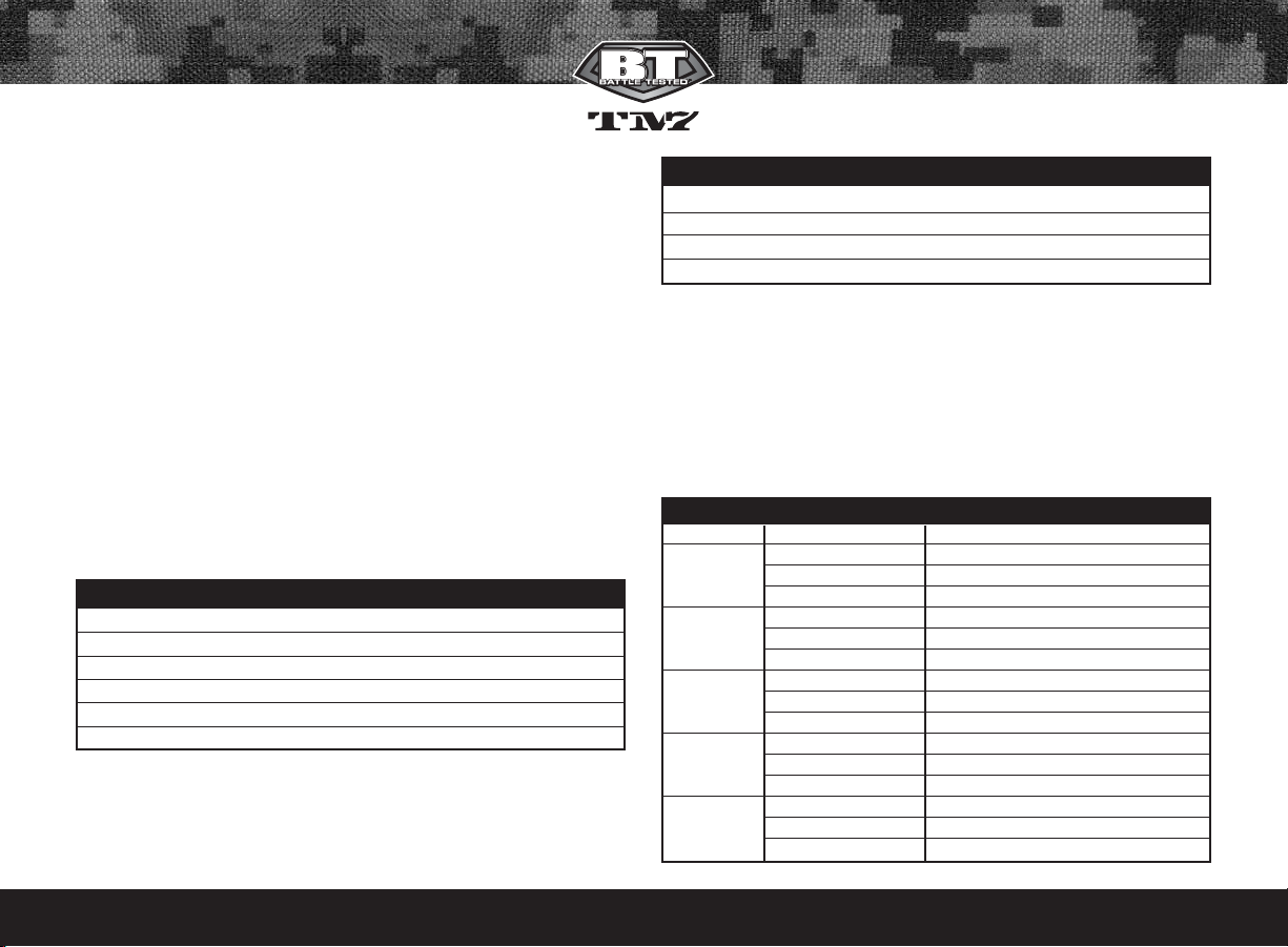
You will notice four (4) set screws in your
trigger. These can be adjusted with a
1/16" Allen key. Make small adjustments and check that the trigger is activating the solenoid.
• The (1) First set screw adjusts the trigger activation point. For best results,
the activation point should be set right in the middle of the total trigger
movement from front to back.
• The (2) Second set screw adjusts forward movement, and stop point.
• The (3) Third set adjusts the trigger return spring tension.
• The (4) Fourth set screw adjusts the rear movement range, and stop point.
Notes:
• If any of the set screws are over adjusted in any direction the TM-7 may
not fire.
• If the trigger travel is adjusted too short, the TM-7 may fire on its own,
repeatedly and/or uncontrollably.
3 Flash = 4 BPS
4 Flash = 4.5 BPS
5 Flash = 5.5 BPS
6 Flash = 6.5 BPS
7 Flash = 7.5 BPS
8 Flash = 8.5 BPS
9 Flash = 9.5 BPS
Ramping Point
Flashes/PTR (Pulls to Ramp)
1
2
3
4
Page 11

BTPAINTBALL.COM
10
13. General Maintenance
CAUTION: Before attempting to perform any maintenance operations,
make sure that all paintballs and propellant sources have been removed
from the marker and that the regulator gauge reads 0 psi. Install a barrel blocking device, move the Selector switch to the OFF position and push
Power button and hold for over 2 seconds until the LED light changes
from Red to Green, and keep the TM-7 power OFF.
Keep your TM-7 clean and lubricated to eliminate the friction that would
prevent reliable operation. Clean and lube the marker before each use,
and do not put it away dirty. Do not use oils made for paintball markers,
real firearms or pneumatic tools, do not use oils at all. Do Not use petroleum-based lubricants in the lubrication of this marker. Teflon or silicon
(NON-spray only) lubricants designed for use on o-rings may be used for
lubrication for the bolt, bolt guide and poppet area only. Only use grease
supplied with your TM-7.
The outer plastic shell can be rinsed with warm water once all the internals
have been removed. Make sure it is fully dry before reassembling the TM-7.
Notes:
• Do not rinse the Tm-7 Shell under water without fully disassembling the
marker, as you will damage the electronics.
• Do Not work on your TM-7 until the Air source is removed and it is verified
that the regulator gauge reads 0 psi and no air is trapped in the TM-7.
14. TM-7 Assembly/Disassembly
CAUTION: Before attempting to perform any marker disassembly, make
sure that all paintballs and propellant sources have been removed from
the marker and that the regulator gauge reads 0 psi. Install a barrel
blocking device, move the Selector switch to the Safety position and push
Power button and hold for 2 seconds until the LED light changes from Red
to Green, and keep the TM-7 power OFF.
Disassembly Tips
• Make sure you have a clean area to work on your marker.
• Do not remove the Air Transfer tube from the body and regulator; these
parts are assembled tightly at the factory to prevent leaks.
• When separating the Shell for the first time, locate the Selector shaft
and Trigger, notice their position for easy reassembly.
• Make sure the Main spring is installed correctly on the Bolt, as it needs
to be installed in the right direction.
• Install the Stock lock and Stock at the same time. Install the Stock lock
into the Stock arms and place them in the shell at the same time.
• After reassembling the TM-7 recheck your trigger activation settings.
Visit PaintballSolutions.com for additional information.
Barrel
It is recommended that the barrel be removed before and other maintenance or disassembly is performed. Simply turn the barrel counter-clock
wise to remove. Use warm water and a barrel cleaning device to keep the
Barrel in top condition.
Rear Sight
The rear sight rail can be removed by loosening the screw with a 1/8”
Allen wrench and then lift the rear sight off.
Feed Elbow
To remove the feed elbow, push the release button on the left side of the
feed elbow and slide it forward about 1 inch and lift it off. The Feed elbow
does not slide off the front of the rail.
Page 12

BTPAINTBALL.COM
11
Note: Make sure when the feed elbow is reinstalled, it lines up with the
hole on the right side of the shell.
Foregrip
Using a 7/64" Allen wrench, remove the socket head screw and slide the
foregrip forward and off of the body.
Selector Arm
It is not necessary to remove the selector arm when dissembling the TM-
7. Using a 1/16" Allen wrench, remove the flat head screw which holds
the selector arm to the selector shaft.
Note: The Selector Arm is keyed into the selector shaft. Make sure they
are aligned before reinstalling the selector arm screw.
Grips
Using a 5/64" Allen wrench, remove the four 6-32 button head screws holding
the grips in place. Notice that the lower screws are longer than the top grip screws.
Separating Shell
Once the parts above have been removed the shell can now be separated. The shell is separated by loosening the shell screws.
• Using a 7/64" Allen key loosen the 7 socket head screws, located on
the left side shell.
• Also remove the 2 flat head screws, located above the regulator with a
5/64" Allen wrench.
• The left side shell can now be separated from the right, by lifting it off.
Notes:
• It is not necessary to remove the picatinny side rails to separate the shells.
• Once the left shell has been removed, there are several components
which will be loose. These include the battery door, trigger, trigger guard, trigger spring, and stock assembly. Make sure you do not lose any of these parts.
Trigger
The trigger can be removed by simply lifting it out of the right side shell.
When reinstalling it, make sure the trigger spring is seated correctly. See
the picture below for correct installation.
Trigger spring
The trigger spring serves as a dual purpose spring. It holds the selector
switch in position and gives the trigger a spring return. See the picture
below for correct installation.
Selector Shaft
The selector shaft sits in the right side shell and connects to the selector switch arm, when fully assembled. You will notice, on one side of the shaft 4 keys
that sit into the trigger spring. Make sure these
keys line up before putting the shell back together.
See the picture below for correct installation.
Stock and Stock Lock
The stock assembly and stock lock assembly can be easily removed once
the outer shell is separated. If you decide not to use the stock, the TM-7 also
comes with a cover plate for the back of the shell.
Note: Notice how the stock lock sits in the shell
before removing it, so it’s easier to reinstall.
Removing the Body from the Shell
Note: Before removing the body assembly from
the shell, it will be necessary to unplug the battery
harness and lift the wiring harness guide.
Page 13

BTPAINTBALL.COM
12
• Separate the shells as described, remove the stock lock and stock
assemblies.
• Disconnect the the battery harness and lift the wiring harness guide.
• Lift the body assembly from the right side shell
Removal, Installation and Cleaning of Ball Detents
• Using a 5/64" Allen key, insert Allen key into detent cover and turn
counter-clockwise.
• Clean the detents with a damp cloth and apply a small amount of supplied grease to the outer sides of the detents if sticking is an issue.
• Installation is the reverse of the removal. Do not over tighten the Ball
Detent covers!
Note: Be careful not to lose any of the detent parts as they are small.
Removal of Bolt Guide Assembly
Caution: Make sure the TM-7 is completely empty of air before removing
the Bolt Guide Assembly.
• Using a 1/8" Allen key, insert it into
the rear retention screw, turn the
Allen key counter-clockwise and completely remove the screw.
• This will allow you to pull out the Bolt
and Bolt Guide Assembly. If assembly
does not easily slide out, insert a barrel swab into the front of the body
and push out the Bolt and Bolt Guide Assembly.
Maintenance of Bolt and Bolt Guide
• Inspect the o-rings on both the Bolt and Bolt guide for any wear or
damage. Replace damaged or worn o-rings if necessary.
• Lubricate all o-rings on Bolt and Bolt Guide with supplied grease. Only
a small amount of grease is needed.
Maintenance of Poppet
Note: Notice how far the Bolt Guide Cap is into the Bolt Guide. When rein-
stalling the Bolt Guide Cap make sure it is at about the same location.
• Use a 7/64" Allen key and insert it into the side of the Bolt Guide Cap.
Turn counter clockwise until Bolt Guide Cap is completely removed.
• Remove the Poppet Spring, being careful not to lose it.
• Use 1/8" Allen key and carefully insert it into the front of the Bolt Guide.
Push the Poppet out the back of the Bolt Guide. Be careful not to damage the Poppet front sealing face.
• Inspect and lubricate Poppet O-ring and be careful not to lubricate the
front Poppet Seal.
Re-Installation of Poppet
and Bolt Guide Cap
• Place Poppet into the back of
the Bolt Guide and gently push forward. If installed properly the Poppet
will be all the way forward resting on the bolt guide internal face.
• Install the Poppet spring back into the back of the Poppet.
• Using the 7/64" Allen key, screw the Bolt guide cap clockwise back into
the Bolt Guide. Screw the Bolt Guide Cap all the way in to help seat the
poppet and then turn it out one turn. Further adjustment over a
Page 14

BTPAINTBALL.COM
13
chronograph will be needed to achieve desired velocity.
Re-Installation of Main Spring, Bolt and Bolt Guide Assembly
• Slide the Main Spring onto Bolt, and then the Bolt onto Bolt Guide, so it
is one assembly. You will notice, one end of the spring is smaller and will
lock onto the bolt.
• Insert Bolt Assembly
back into the body.
• Line up the alignment
hole on the guide with the alignment pin on the body and slide the bolt
assembly fully forward to the body.
• Holding the bolt assembly tight into the back of the body with one hand,
reinstall the Bolt Guide retention screw and tighten using the 1/8" Allen key.
Circuit Board Removal
The Circuit Board should only need to be removed to clean the break beam eyes.
• Remove the Body Assembly from the shell.
• Using a 5/64" Allen key, remove the two Circuit Board screws and
gently remove the Circuit Board.
Wiring Harness Removal
Note: The wiring harness should only need to
be removed if you are washing the right shell
of the TM-7.
• Carefully pull the 2 battery spring tabs out of
the right side shell, using needle nose pliers.
Be careful not to break the wires from the battery tabs.
• Then lift the wiring harness guide OFF,
and remove harness.
Re-Installation of Wiring Harness
Make sure the wire harness is routed
through the circuit board and along the
body above the circuit board as shown
and not through the trigger area. Failure
to route the wires properly will result in
destruction of the wires during re-installation of the shell, and can result
in an electrical fire when the battery is installed. Destruction of the wire
harness is not covered under warranty.
Regulator Hex Adjustment
The Regulator has 2 Hex spacers which hold the shell together and the grips
on. If they need adjusting, simply insert an Allen key and push it thru the
shell and hex. This will align the hex spacers and the screw will go in easily.
15. Storage and Transportation
IMPORTANT: Never carry your TM-7 uncased when not on a playing field.
The non-playing public and law enforcement personnel may not be able
to distinguish between a paintball marker and firearm. For your own
safety and to protect the image of the sport, always carry your TM-7 in a
suitable marker case or in the box in which it was shipped.
• Your TM-7 must be clear of all paint and propellant when not being used.
• Make sure the TM-7 marker is OFF. Push the Power button and hold for
2 seconds until the LED light changes from Red to Green.
• Put the barrel blocking device in its place. Make sure the marker is clean.
• Store your TM-7 in a clean, cool, dry place.
Page 15

BTPAINTBALL.COM
14
• Keep your TM-7 away from unauthorized and unsafe users.
• It may be a good idea to remove the battery when storing your TM-7
to prevent unauthorized use.This is not a toy. Misuse may cause serious injury or death. Eye Protection designed specifically for paintball
must be worn by the user and persons within range. Recommend 18
years of age or older to purchase. Persons under 18 years of age must
have adult supervision.
Your TM-7 must be clear of all paint and any source of propellant during
transportation to and from the playing field. Keep your barrel blocking
device in place. Keep the TM-7 Marker switched OFF. Protect your TM-7
from excessive heat during transportation.
Observe and obey all local, state and federal laws concerning the transportation of paintball markers. For information concerning any of the
laws in your area, contact your nearby law enforcement agency.
If you must ship your TM-7 for any reason, the box in which you purchased
the marker should be used to protect your marker against rough handling
during transport.
Never ship charged CO
2 or pressurized gas cylinders!
16. Trouble Shooting Guide
Note: If you are experiencing any problems and you are using any
aftermarket parts, it is necessary to re-install the factory parts and
re-test before attempting any troubleshooting, as non-factory aftermarket parts are not designed by BT Paintball to work in the TM-7,
and they may be the cause of the problems. Do not contact BT
Paintball until you have returned the TM-7 to factory stock condition
and tested.
Does not
turn on
Make sure
you have a
fresh battery.
If you have tried several different batteries, check to make
sure the battery harness is plugged in to the board properly.
If it is, unplug the battery from the harness for 5 minutes,
then plug back in and try again.
Does not
fire
Make sure
marker is
turned on.
Make sure you
have a paintball in the
chamber.
Trigger may
need to be
adjusted.
Check the LED light on the back of the foregrip. The LED
should be rapidly blinking green when a paintball is present.
The anti-chop eye system prevents the marker from firing
unless a ball is present. Never put anything other than a
paintball down the feed neck of the TM7.
Check the LED light on the back of the foregrip. While holding
in the trigger, the LED should stay red in the background, and
not be red when the trigger is released. If it is not that way,
then the trigger may need to be adjusted. See the “Adjusting
your trigger” section earlier in the manual.
Does not
fire with
eyes
turned OFF
Trigger may
need to be
adjusted.
Solenoid
may not be
connected
properly.
Solenoid may
need to be
reset.
Check the LED light on the back of the foregrip. While holding in the trigger, the LED should stay red in the background, and not be red when the trigger is released. If it is
not that way, then the trigger may need to be adjusted. See
the "Adjusting your trigger" section earlier in the manual.
Check to make sure the solenoid is connected properly to
the sensor board. If it is, the solenoid may need to be reset.
To reset the solenoid, with the eyes OFF, pull the trigger
repeatedly until the solenoid makes a loud clicking sound
again with each trigger pull, but do not pull the trigger
more than 10 times, as this can damage the solenoid. If
after 10 pulls the solenoid still doesn't click, it may need to
be serviced.
Page 16

BTPAINTBALL.COM
15
Leaks
constantly
through
the
chamber
Solenoid may
need to be
reset.
To reset the solenoid, with the eyes OFF, pull the trigger
repeatedly until the solenoid makes a clicking sound again
with each trigger pull, but do not pull the trigger more than
10 times, as this can damage the solenoid. If after 10 pulls
the solenoid still doesn't click, it may need to be replaced.
Multiple
balls fired
from only
one shot
Shoots
more than
once from
one trigger
pull
Regulator
leaks from
bottom
plug
Ball detents
may be sticking open.
Loader forcing
paintballs too
hard into marker.
Battery may
be low.
Trigger may need
to be adjusted.
Adjust overpressurization
relief valve.
Remove both ball detent covers and clean the ball detents with
a cloth. You may also add some grease to the outer surface of
the detents to make sure they are not sticking within the covers.
Try a different loader, such as the Empire Magna Drive
Loader. If using a Halo series or Empire Reloader B series
loader, try installing an Empire Magna Clutch Upgrade Kit..
Replace battery with a fresh Duracell or Energizer brand
alkaline 9-volt.
Make sure the trigger has plenty of travel both before and
after the activation point.
The plug on the underside of the regulator is an over-pressurization relief. If it is leaking, most likely the regulator is set
to too high of a pressure and needs to be lowered. If the
regulator is set to 200 psi or less and the over-pressurization
relief is still leaking, it is possible to turn the plug cap just a
small amount in the clockwise direction, until the leak stops.
Regulator
is slow to
recharge
Air tank is not
screwed all
the way into
the TM7’s
regulator ASA.
If during rapid firing the first ball comes out of the barrel at
full velocity and following shots decrease substantially, watch
the gauge on the TM7 regulator to see if the needle drops
down significantly and is slow to come back to the set pressure. This is typically the result of not screwing your air tank in
enough. When screwing your air tank into the TM7’s regulator ASA, it is important to not stop as soon as the marker
pressurizes, but to continue turning until the air tank stops. It
is also acceptable to install the air tank when it is empty, then
have it filled by a professional while it is installed. This will
ensure that you get the maximum air flow from your air tank.
Regulator
pressure
spikes
Regulator
adjusted too
high.
If the needle on the regulator’s gauge climbs well over 200
psi when attempting to install the air tank, first remove the
brass adjustment screw in the front of the regulator and try
again to install the air tank. If the needle reads 0, reinstall the
adjustment screw and turn in until the needle reads 200 psi.
Breaks
paint in
chamber
Eyes are
turned off.
Low quality
or brittle
paintballs.
Loader pushing too hard.
Bolt or bolt
guide o-rings
may be worn.
Bolt front seal
may be
missing.
Check valve
may be
missing.
Only fire paintballs with the marker’s eyes on.
Do a paintball drop test. On a level and smooth, hard, outdoor surface, such as concrete or asphalt pavement, drop
ten paintballs one at a time from about 5 feet high. Don’t
toss them up or throw them at the ground, just drop them
straight down. If more than 3 paintballs out of 10 break,
the paintballs are bad and should not be used in the TM7.
In the case of higher-end tournament-grade paintballs, it
may be possible to tune the TM7 to successfully fire brittle
paintballs. Since all conditions are different, it is best to ask
for help with this from your local pro shop.
Try a different loader, such as the Empire Magna Drive
Loader. If using a Halo series or Empire Reloader B series
loader, try installing an Empire Magna Clutch Upgrade Kit.
Air blowing past worn o-rings can easily break paintballs in
the feed neck. Replace the bolt o-rings and the smaller 3
bolt guide O-rings and apply fresh grease.
Make sure the bolt front seal is in place and has a light
application of grease to reduce friction.
Make sure the check valve is in place. Without the check
valve, the forward force on the bolt is too great and can be
too hard on the paintballs.
Page 17

BTPAINTBALL.COM
16
Breaks
paint in
chamber
Ball detents
may be dirty
or worn.
Regulator
pressure may
be set too
high.
Clean the ball detents. If necessary, apply a small amount
of grease around the outer surface to reduce friction inside
the ball detent covers. Replace if tips are worn down.
Lower regulator pressure.
Cycles very
slowly
Bolt or bolt
guide o-rings
may need
grease.
Rate-of-fire
setting may
be adjusted
too low.
Loader may
not be
feeding fast.
Clean off old grease from the bolt and bolt guide o-rings,
as well as the bolt front seal, and apply fresh grease.
Raise Rate of Fire setting.
Check your loader’s batteries or use a faster loader.
Inconsistent
velocity
Pressure may
be set too low.
Marker may
need to be
greased.
Dwell may be
set too low or
too high.
Check valve
may be missing.
Low pressures have difficulty supplying enough volume to
maintain a constant velocity. Do not lower your TM7’s
regulator pressure below 180 psi.
Clean old grease from the poppet, the bolt and bolt guide
o-rings and apply fresh grease. Do not use too much, as it
will prevent the moving parts from cycling smoothly.
Reset the dwell setting to the factory default.
Make sure the check valve is in place.
Inconsistent
velocity
Battery may
be low.
Poppet o-ring
may be worn.
Replace battery with a fresh Duracell or Energizer brand
alkaline 9-volt.
Replace poppet o-ring and apply fresh grease.
Velocity
drops off
when firing
multiple
shots
Air tank is not
screwed all the
way into the
TM7’s regulator ASA.
If during rapid firing the first ball comes out of the barrel at
full velocity and following shots decrease substantially,
watch the gauge on the TM7 regulator to see if the needle
drops down significantly and is slow to come back to the
set pressure. This is typically the result of not screwing your
air tank in enough. When screwing your air tank into the
TM7's regulator ASA, it is important to not stop as soon as
the marker pressurizes, but to continue turning until the air
tank stops. It is also acceptable to install the air tank when
it is empty, then have it filled by a professional while it is
installed. This will ensure that you get the maximum air
flow from your air tank.
Scratches
on bolt
Spring may be
damaged.
This can cause negative performance. The main spring should
be repaired by a trained technician or it can just be replaced.
Selector
switch not
working
Selector may
be installed
incorrectly
Check to be certain that the selector switch is installed with
keys facing down toward the trigger spring.
Leaks at
times while
shooting
multiple
shots
Poppet may be
sticking open.
Battery may be
low.
Solenoid may
be sticking
open.
Clean the old grease from the poppet o-ring and apply
fresh grease. If that doesn't help, replace the poppet o-ring
and apply fresh grease.
Replace battery with a fresh Duracell or Energizer brand
alkaline 9-volt.
If the solenoid is sticking open occasionally, the regulator
pressure may be set too high. If the pressure is set to 200
psi or less, then the solenoid may be filled with dirt and/or
grease. See Maintenance section for instructions on how to
clean the solenoid.
Page 18

BTPAINTBALL.COM
17
Schematic
#
Description SKU
#
1 SELECTOR SCREW (flat head 4-40 x .5) 17650
2 FRAME SCREW (flat head 6-32 x .313) 17651
3 CIRCUIT BOARD SCREW (button head 6-32 x .157) 17652
4 GRIP SCREW-TOP (button head 6-32 x .250) 17653
5 GRIP SCREW-BOTTOM (button head 6-32 x .438) 17654
6 SHORT SHELL SCREW (socket head 6-32 x .5) 17655
7 LONG SHELL SCREW ( socket head 6-32 x 1.0) 17656
8 SHELL HEX NUT (6-32 .25 wide x .092 thick) 17657
9 SOLENOID SCREW (button head 10-24 x .250) 17658
10 BOLT GUIDE RETENTION SCREW (custom) 17659
11 TRIGGER SET SCREW ( 6-32 x .250 flat point) 17602
12 FEED ELBOW WASHER (.257 ID, .438 OD, .032 Thk) 19422
13 FEED ELBOW BOLT (socket head 1/4-20 x 1.0) 19420
14 FEED ELBOW NUT (1/4-20 .438 wide x .235 thick) 19421
15 REAR SIGHT SCREW (socket head 10-32 x .656) 19413
16 REAR SIGHT NUT (10-32 .375 wide x .130 thick) 19415
17 BOLT RUBBER TIP 17533
18 SPRING MAIN 17535
19 BOLT 17661
20 BOLT GUIDE 17662
21 BOLT GUIDE SMALL 0-RING 17537
22 BOLT / BOLT GUIDE LARGE O-RING 17534
23 POPPET (with spring) 17539
24 POPPET O-RING 17540
25 BOLT GUIDE CAP 17664
26 BOLT GUIDE CAP O-RING 17538
27 SOLENOID ASSEMBLY (complete) 17665
28 REGULATOR ASSEMBLY (complete) 17671
29 REGULATOR GAUGE (plain 300 psi) 17672
30 HEX BRASS (6-32 internal threads) 17673
Schematic
#
Description SKU
#
31 REGULATOR OPP ASSEMBLY (complete) 17597
32 BALL DETENT ASSEMBLY (complete) 17541
33 MAIN BODY 17677
34 BARREL 17678
35 CIRCUIT BOARD 17679
36 AIR TRANSFER TUBE 17680
37 CHECK VALVE (air restrictor) 17531
38 SOLENOID AIR TRANSFER ORINGS 17682
39 FORE-GRIP ASSEMBLY 17683
40 STOCK ASSEMBLY 17689
41 STOCK LOCK ASSEMBLY 17695
42 FEED ELBOW ASSEMBLY 19385
43 REAR SIGHT ASSEMBLY 17700
44 SINGLE TRIGGER ASSEMBLY 17702
45 TRIGGER GUARD SINGLE 19399
46 TRIGGER ACTIVATION SET SCREW w/magnet 17564
47 TRIGGER SPRING 17704
48 SELECTOR SWITCH SHAFT (complete w/magnets) 17705
49 SELECTOR SWITCH ARM 17706
50 SHELL LEFT SIDE 17707
51 SHELL RIGHT SIDE 17708
52 PICATINNY SIDE RAIL 17709
53 BATTERY DOOR 17711
54 POWER BUTTON 17712
55 STOCK COVER PLATE 17713
56 CIRCUIT BOARD HARNESS (Not shown) 17714
57 BATTERY HARNESS (Not shown) 17715
58 WIRING HARNESS GUIDE 17716
59 GRIPS 17717
60 Poppet Spring 17623
61 Stock Block 17718
Page 19

BTPAINTBALL.COM
18
Page 20

BTPAINTBALL.COM
19
Page 21

BTPAINTBALL.COM
20
18. Warranty Information
TM-7 LIMITED WARRANTY
BT Paintball warrants the replacement of any original part due to defect in
materials and/or workmanship of this marker. This warranty will be in effect
for twelve (24) months for parts and twelve (24) months for labor following
the original date of purchase for the original purchaser. Warranty is only
retained if the marker is purchased as new; markers purchased used are
not covered by warranty. Such warranty service will be provided only if the
warranty registration card included with this manual is filled in completely
and a copy of the original receipt is on file at BT Paintball. All other services
will be duly charged by over the phone credit card and shipped UPS.
BT Paintball will replace, without charge, any original part that is determined by BT Paintball to be defective under the terms of this warranty.
However, shipping charges are not covered hereunder. Failure due to an
accident, abuse, neglect, modification, loss, normal wear, operator error,
maintenance by other than an authorized BT Paintball dealer, or use of
parts inconsistent with the use originally intended for the marker as sold,
is not covered by this warranty. This warranty does not apply to wearable
parts such as o-rings, screws, poppet seal, ball detents, etc.
There are no other warranties or guarantees, expressed or implied, made
by BT Paintball on this marker. The sole and exclusive liability of BT
Paintball and/or its authorized dealers, affiliates, or agents pursuant to
this warranty will be for repair or replacement of the defective part; incidental or consequential damages are expressly excluded hereunder.
Removing or disassembly of the original regulator voids all warranties,
unless replaced with another TM-7 Bottomline Regulator produced by BT
Paintball.
If marker is to be sent in for repair, the marker must consist of all
factory stock parts. Markers with aftermarket parts will not be warranted.
For warranty parts, service or information contact:
Paintball Solutions
www.paintballsolutions.com
55 Howard Ave.
Des Plaines, IL 60018
1-800-220-3222
TM-7 Instruction Manual Version 1.0
Page 22

BTPAINTBALL.COM
1
1. Rules for Safe Marker Handling
IMPORTANT: Never carry your TM-7 uncased when not on a playing field.
The non-playing public and law enforcement personnel may not be able
to distinguish between a paintball marker and firearm. For your own safety and to protect the image of the sport, always carry your TM-7 in a suitable marker case or in the box in which it was shipped.
• Treat every marker as if it were loaded.
• Never look down the barrel of a paintball marker.
• Keep your finger OFF the trigger until ready to shoot.
• Never point the marker at anything you don’t wish to shoot.
• Keep the marker on “safe” until ready to shoot.
• Keep the barrel blocking device in/ on the marker’s barrel when not
shooting.
• Always remove paintballs and propellant source before disassembly.
• After removing air source, point marker in safe direction and discharge
until Marker is degassed.
• Store the marker unloaded and degassed in a secure place.
• Follow warnings listed on the air source for handling and storage.
• Do not shoot at fragile objects such as windows.
• Every person within range must wear eye, face and ear protection designed
specifically to stop paintballs and meeting ASTM standard F1776.
• Always measure your marker’s velocity before playing paintball and
never shoot at velocities in excess of 91.44 meters (300 feet-per-second).
READ OWNERS MANUAL BEFORE USING.
2. Introduction and Specifications
Congratulations on your selection of the TM-7 paintball marker. The TM-7
is made to provide you with many years of reliable performance. We are
honored that you have chosen the TM-7 as your marker of choice and
hope you enjoy using this high quality product.
The patented Valve design, Slip Stream™ Solenoid, Hall Effect Sensor
Trigger, Four Position Selector Switch, set new standards for marker technology. The TM-7 is precision engineered from Aircraft grade Aluminum and
Composite, to meet the demands of the most competitive players, teams,
and climates. The ultimate intent of the TM-7 is to exceed your expectations.
We expect you to play hard and play frequently and thus the TM-7 was
built with this in mind. All internal parts, wear, and contact surfaces have
been heat treated or hard anodized. The toughest and most resilient materials and components have been used in the construction of this marker.
The TM-7 operates on Low-Pressure. The main operating pressure is 180-200 PSI.
The pressure can be nominally adjusted and monitored visually via the gauge on
the bottom-line regulator. There is no secondary regulator to worry about.
TTMM--77 SSppeecciiffiiccaattiioonnss
Model- TM-7
Barrel- 9“ Ported Barrel
Caliber-68
Action- Semi Auto, Ramping, and Full Auto
Air source- Compressed Air
Battery- One 9 Volt
Cycle Rate- 20 BPS
Shell Material- Composite
Main Body material- Aluminum
Accuracy Range- 150ft +
Weight– 2.5 lbs
IInncclluuddeedd wwiitthh yyoouurr TTMM--77
- 9” Barrel (.691 bore)
- Allen Keys
- Spare Parts
- Barrel Blocking Device
- One 9 Volt Battery
Page 23

BTPAINTBALL.COM
Page 24

 Loading...