


FDS-366T OMNIDRIVE™
User Manual
Connect here first...

FDS-366T
ZM10019 issue 4 CB/PW/DN/DP/JWK
Software version 2.00
IMPORTANT SAFETY INFORMATION
DO NOT REMOVE COVERS.
NO USER SERVICABLE PARTS INSIDE.
REFER SERVICING TO QUALIFIED SERVICE PERSONNEL.
THIS EQUIPMENT MUST BE EARTHED.
IT SHOULD NOT BE NECESSARY TO REMOVE ANY PROTECTIVE
EARTH OR SIGNAL CABLE SHIELD CONNECTIONS TO PREVENT
GROUND LOOPS. ANY SUCH DISCONNECTIONS ARE OUTSIDE
THE RECOMMENDED PRACTISE OF BSS AUDIO AND WILL
RENDER ANY EMC OR SAFETY CERTIFICATION VOID.
REGULATORY INFORMATION
This equipment has been tested and found to comply with the following European and International Standards for Electromagnetic Compatibility and Electrical Safety:
Emmissions (EU): |
EN55013+A12+A13 |
(1990) |
Generic Immunity (EU): |
EN50082-1 |
(1992) |
Mains Harmonics (EU) |
EN61000-3-2 |
(1995) |
Voltage Fluctuations (EU) |
EN61000-3-3 |
(1995) |
Electrical Safety (EU): |
EN60065+A11 |
(1993) |
Electrical Safety (USA): |
UL813/ETL |
(1996) |
For continued compliance with international EMC legislation ensure that all input and output cables are wired with the cable screen connected to Pin 1 of the XLR connectors.
The input XLR Pin 1 is connected to the chassis via a low value capacitor, providing high immunity from ground loops whilst ensuring good EMC performance.
The FDS-366T Omnidrive was designed and developed by BSS Audio, Hertfordshire, UK.
In keeping with our policy of continued improvement, BSS Audio reserves the right to alter specifications without prior notice.
- 2 -

FDS-366T
Contents
FDS-366T Omnidrive compact plus
1.0 |
Primary Checks ......................................................................................... |
8 |
2.0 |
Installation ................................................................................................. |
8 |
3.0 |
Warranty Information ............................................................................... |
9 |
About the FDS-366T Omnidrive Compact Plus............................... |
10 |
4.0 Introduction ............................................................................................ |
11 |
5.0 Features .................................................................................................... |
12 |
What is DEQ? ................................................................................................. |
16 |
6.0 Dynamic Equalisation .............................................................................. |
16 |
Notes and Uses .................................................................................................................. |
17 |
7.0 Crossover Shapes and Frequencies .......................................................... |
19 |
Thiele Crossover ................................................................................................................ |
21 |
Crossover comparison chart ............................................................................................... |
22 |
Phase Compensation .......................................................................................................... |
23 |
Stereo 3-Way with mono sub-bass. ................................................................ |
24 |
8.0 Typical Applications ................................................................................. |
24 |
6-Way zoning distribution .............................................................................. |
25 |
LCR cinema systems (3x2-way)....................................................................... |
25 |
Triple Bi-amp (Stage monitors) ........................................................................ |
25 |
Mono 6-way ................................................................................................... |
26 |
Stereo 6-way (example) .................................................................................. |
26 |
9.0 Front Panel ............................................................................................... |
27 |
10.0 Rear panel .............................................................................................. |
29 |
Using the FDS-366T Omnidrive Compact Plus ............................... |
30 |
Voltage setting ................................................................................................ |
31 |
11.0 Connections - Mains Power .................................................................. |
31 |
AC Power fusing ............................................................................................ |
32 |
Connections - Audio...................................................................................... |
33 |
Balanced wiring.................................................................................................................. |
33 |
- 3 -

FDS-366T
Unbalanced wiring ............................................................................................................. |
34 |
MIDI................................................................................................................................... |
35 |
RS232 Serial ....................................................................................................................... |
35 |
RS485 Serial ....................................................................................................................... |
35 |
Program Select Port ............................................................................................................. |
36 |
12.0 Navigation .............................................................................................. |
37 |
The Navipad ................................................................................................... |
37 |
The Rotary Encoder ........................................................................................ |
37 |
13.0 Default Screen ....................................................................................... |
38 |
14.0 Quick Start Guide .................................................................................. |
39 |
Keep relative delays while delaying a group ....................................................................... |
44 |
Name a band ..................................................................................................................... |
44 |
15.0 Quick Reference - How to ... ................................................................. |
44 |
Use delays for driver alignment .......................................................................................... |
44 |
Make a band full range ...................................................................................................... |
45 |
Add EQ for Constant Directivity horns................................................................................ |
45 |
Load custom logos ............................................................................................................. |
45 |
Programming functions in depth ..................................................... |
46 |
Recalling a Program ........................................................................................................... |
47 |
16.0 Program Functions - Recall .................................................................... |
47 |
Storing a Program ............................................................................................................... |
48 |
Program Functions - Store.............................................................................. |
48 |
Store Lock .......................................................................................................................... |
48 |
Program lock ...................................................................................................................... |
49 |
Store Type .......................................................................................................................... |
49 |
Delete Program .................................................................................................................. |
50 |
Card types .......................................................................................................................... |
51 |
Compatible Cards .............................................................................................................. |
51 |
Storage life ......................................................................................................................... |
51 |
PC Card format .................................................................................................................. |
51 |
17.0 PC Card Usage ....................................................................................... |
51 |
FDS-355 compatibility ....................................................................................................... |
52 |
Computer compatibility...................................................................................................... |
53 |
- 4 -

FDS-366T
18.0 Utilities .................................................................................................. |
53 |
1. Configuration.................................................................................................................. |
54 |
2. Stereo Link ...................................................................................................................... |
54 |
3. Sum Type........................................................................................................................ |
54 |
5. Phase Comp ................................................................................................................... |
55 |
4. Xover Adjust ................................................................................................................... |
55 |
6. Alignment Assistant ......................................................................................................... |
56 |
Method .............................................................................................................................. |
56 |
Microphone placement and connection .............................................................................. |
56 |
Procedure........................................................................................................................... |
57 |
Selecting bands to measure ................................................................................................. |
57 |
Adjusting the stimulus level ................................................................................................. |
58 |
Notes ................................................................................................................................. |
58 |
7. Delay Corrn (Correction) ................................................................................................. |
60 |
8. Temperature.................................................................................................................... |
61 |
9. Limit units ....................................................................................................................... |
61 |
10. Delay units ................................................................................................................... |
61 |
11. Brightness ..................................................................................................................... |
61 |
12. Contrast ........................................................................................................................ |
61 |
14. Owner lock .................................................................................................................. |
62 |
13. Lock out ....................................................................................................................... |
63 |
Setting up 'Owner' Locks .................................................................................................... |
63 |
Storing Owner Programs ..................................................................................................... |
64 |
Adding further locks ........................................................................................................... |
64 |
15. OEM Lock .................................................................................................................... |
65 |
Storing OEM Programs ........................................................................................................ |
66 |
Adding further locks ........................................................................................................... |
66 |
OEM & Owner Locks .......................................................................................................... |
67 |
Configuration parameter note .............................................................................................. |
67 |
Lockable Utilities ................................................................................................................ |
67 |
17. Serial Port ..................................................................................................................... |
68 |
18. MIDI Mode ................................................................................................................... |
68 |
16. Input A/AES .................................................................................................................. |
68 |
19. MIDI Channel ............................................................................................................... |
69 |
20. MIDI Dump .................................................................................................................. |
69 |
23. Delete Program ............................................................................................................. |
70 |
21. Backup & Swap ............................................................................................................ |
70 |
22. Store Gain Trims ............................................................................................................ |
70 |
24. Format Card.................................................................................................................. |
70 |
19.0 Input Channels ....................................................................................... |
71 |
2. Delay ............................................................................................................................. |
72 |
3. EQ Bypass ...................................................................................................................... |
72 |
- 5 -

FDS-366T
4. Dynamic EQ ................................................................................................................... |
72 |
1. Gain ............................................................................................................................... |
72 |
DEQ ................................................................................................................................... |
73 |
Thr (Threshold) ................................................................................................................... |
73 |
Ratio .................................................................................................................................. |
73 |
Attack and Release ............................................................................................................. |
74 |
Atk (Attack) ......................................................................................................................... |
74 |
Rel (Release) ....................................................................................................................... |
74 |
20.0 Output Channels .................................................................................... |
75 |
1. Name ............................................................................................................................. |
76 |
2. Source ............................................................................................................................ |
76 |
3. Low Shape ..................................................................................................................... |
77 |
Low Freq/Xover .................................................................................................................. |
77 |
4. High shape ..................................................................................................................... |
77 |
High Freq/Xover ................................................................................................................. |
77 |
6. Band gain ....................................................................................................................... |
78 |
5. Phase ............................................................................................................................. |
79 |
Polarity .............................................................................................................................. |
79 |
7. Limiter ........................................................................................................................... |
79 |
Over (Overshoot) ............................................................................................................... |
79 |
Thr (Threshold) ................................................................................................................... |
79 |
Rel (Release) ...................................................................................................................... |
79 |
Atk (Attack) ........................................................................................................................ |
79 |
Delay ................................................................................................................................. |
80 |
EQ Bypass....................................................................................................... |
80 |
Delay link .......................................................................................................................... |
80 |
DEQ ................................................................................................................................... |
81 |
Thr (Threshold) ................................................................................................................... |
81 |
Ratio .................................................................................................................................. |
81 |
Attack and Release ............................................................................................................. |
82 |
Atk (Attack) ........................................................................................................................ |
82 |
Rel (Release) ...................................................................................................................... |
82 |
Outputs - EQ .................................................................................................. |
83 |
EQ shape ........................................................................................................................... |
84 |
Frequency .......................................................................................................................... |
85 |
Width ................................................................................................................................. |
85 |
Cut/Boost ........................................................................................................................... |
85 |
- 6 -

FDS-366T
Reference Section ........................................................................... |
86 |
|
21.0 |
Serial Communications ......................................................................... |
87 |
MIDI ................................................................................................................................... |
|
87 |
MIDI with PC Control.......................................................................................................... |
88 |
|
Synchronous Control .......................................................................................................... |
88 |
|
RS232 ................................................................................................................................ |
89 |
|
RS485 & Multidrop ............................................................................................................. |
90 |
|
22.0 Troubleshooting ..................................................................................... |
94 |
|
23.0 |
FDS-366T Omnidrive MIDI Implementation ....................................... |
95 |
A.1 FDS-366T MIDI Implementation ............................................................ |
95 |
|
24.0 Default Configuration Settings ............................................................... |
96 |
|
25.0 |
Filter Allocations .................................................................................... |
98 |
26.0 |
Specifications and Block Diagram ......................................................... |
99 |
27.0 |
Block Diagram ..................................................................................... |
101 |
28.0 |
User Notes ........................................................................................... |
102 |
- 7 -
|
|
FDS-366T |
|
1.0 |
Primary Checks |
|
|
|
|
|
|
As part of BSS' system of quality control, this product is carefully inspected before packing to ensure flawless appearance.
After unpacking the unit, please inspect for any physical damage and retain the shipping carton and ALL relevant packing materials for use should the unit need returning.
In the event that damage has occurred, please notify your dealer immediately, so that a written claim to cover the damages can be initiated.
Please fill in the warranty details on the form opposite for future reference.
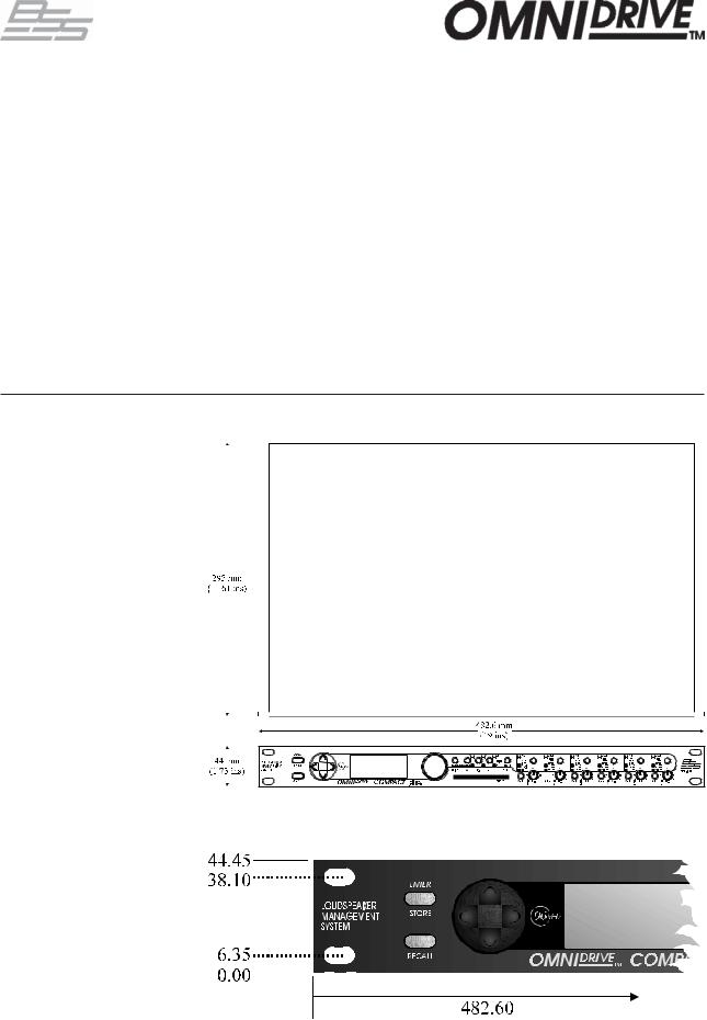
2.0Installation
Fig 3.1 Unit dimensions.
Fig 3.2 Rack
dimensions.
Note all dimension in mm
- 8 -

|
|
FDS-366T |
3.0 |
Warranty Information |
|
When sold to an end user by BSS Audio or a BSS Audio Authorised Reseller, this unit is warranted by the seller to the purchaser against defects in workmanship and the materials used in its manufacture for a period of one year from the date of sale.
Faults arising from misuse, unauthorised modifications or accidents are not covered under this warranty. No other warranty is expressed or implied.
If the unit is faulty it should be sent to the seller of the equipment, in its original packaging with shipping prepaid. The unit will be returned to you when the repair has been completed. If the unit was purchased in the European Union, you may, as an alternative, return the unit to any other BSS distributor in the European Union.
You should include a statement listing the faults found. The unit’s serial number must be quoted in all correspondence relating to a claim.
IMPORTANT We recommend that you record your purchase information here for future reference.
Unit Serial Number:
Dealer Name:
Dealer Address:
Post/Zip Code:
Dealer Phone Number:
Dealer Contact Name:
Invoice/Receipt Number:
Date of Purchase:
Comments or questions regarding the FDS-366T or other BSS products? Contact us at this address:
BSS Audio
Cranborne House
Cranborne Road
Potter Bar
Herfordshire
EN6 3JN
England
Phone (+44) (0)1707 660667. Fax (+44) (0)1707 660742.
Web site, www.bss.co.uk
- 9 -

FDS-366T
About the
FDS-366T
Omnidrive
Compact
Plus
- 10 -
FDS-366T
4.0Introduction
Introducing the BSS Audio FDS-366T Omndrive Compact Plus, an incredibly powerful loudspeaker management system in only 1U of rackspace! Based on BSS Audio's many years of experience building analogue processing devices for the live sound and installed markets, the FDS-366T Omnidrive is an 'all in one' solution for system crossover assignment, EQ, delay and dynamics control.
Processing power
Using custom designed digital signal processing (DSP) technologies BSS Audio are able to deliver far more capabilities in one box than was realisable from a whole rack of analogue equipment only a few years ago. Also as all the processing on the audio signal is kept in the digital domain added noise and phase anomalies usually expected with analogue equivalents are virtually eliminated. The signals are processed at 24bit, 96kHz resolution to achieve a dynamic range greater than 112dB to ensure the best possible audio quality for your system.
Security
Moreover, the comprehensive security features included in the FDS-366T enable the unit to be set up with varying degrees of access to its functionality applied and protected by passwords. Indeed the whole unit can be locked totally to prevent tampering, in installed applications for example.
Routing
An arrangement of 3 inputs and 6 outputs and an additional internal sum of inputs A&B, A+B+C, pre or post input EQ can be matrixed in various combinations to provide a complete loudspeaker management system with integral crossovers, delays, dynamic EQ, and protection limiters.
Applications
The flexibility of the FDS-366T enables it to be employed for many system uses, such as complete 3 way stereo setups or a 2 way LCR combination. Equally FDS-366T Omnidrives can be stacked to run larger 5 and 6 way systems and more.
In stage monitor systems the FDS-366T can function as a triple bi-amp crossover with delay, limiters and EQ. On-stage 'hotspots' caused by monitors with identical signals can be eliminated by applying small delays between wedges.
Furthermore, the FDS-366T can function as a distribution unit to multizone systems where crossovers may be passive or local to the loudspeaker. In this case, the provision of delays and EQ can radically enhance such a system while reducing both processing costs and required rack space.
Upgradeable operating system
The system operating software is held in flash EPROM, which means that upgrading to new software is easy - either via PC card or from a PC via the MIDI or RS-232 ports.
Memorising Setups
60 internal program locations are available to the user for storing system setups, which may be generic system programs or complete venue settings. These memories may be stored onto a PC card for backup or archiving.
- 11 -

FDS-366T
5.0Features
Individual keys to select input and output channels for editing.
Crossover slopes of 6,12, 18, 24 or 48dB per octave.
Filter types:Butterworth, Bessel, Linkwitz-Riley and WHISEWORKSNTM*.
Comprehensive output limiters on each band (mid-filter).
Equalisers and 'dynamic' equalisers on each input and output.
High resolution input and output delays up to 2.6 seconds in approximately 11 microsecond steps.
Input LED metering, showing signals from -12dB to clip level, and SIG.
Output LED metering, showing signals from -20dB to +6dB over limit threshold, and SIG.
Front panel output level trims and mutes.
Polarity reverse on each output.
Phase adjustment for each crossover point, and phase compensation defeat.
PC card port for storage and recall of program settings
Electronically balanced inputs and outputs with transformer output option.
MIDI, RS-232, RS-485 and program change ports on rear panel.
96kHz sample rate and 24bit encoding/decoding for audio excellence.
AES/EBU digital input for direct digital feeds into Omnidrive.
Alignment Assistant for setting up cabinet driver alignments.
Comprehensive system security with control lock out, programmable 'Owner' and 'OEM' locks, and 'Safe' mode available for complete system lock out.
Temperature based delay correction.
If you are familiar with the FDS-355 Omnidrive then look at the extra benefits that the FDS-366T brings, an extra output channel, dynamic equalisation, Thiele crossover shape and 96kHz audio quality to start with!
* The words "WHISEWORKS", "Neville Thiele Method" and NTM logotype are trademarks of Precision Audio Pty. Ltd (registration pending). Manufactured under license from Precision Audio Pty. Ltd. International Patents Pending.
- 12 -

FDS-366T
Features
Some of the features are explained in greater detail here.
•96kHz Sample rate
The FDS-366T operates the A-D and D-A converters and the Digital Signal Processing (DSP) at a sample rate of 96kHz. The use of a higher Nyquist frequency enables the audio bandwidth to extend all the way up to 40kHz. With this extra frequency response we have also been able to incorporate more accurate filter sets for a more natural, open sound.
There is also benefit from the improved filter response shapes when the nyquist frequency (the maximum frequency of which the DSP can correctly process the signal), moves up from 24kHz to 48kHz. Low-pass filters and bell filters then retain their magnitude and phase response shapes more accurately.
•AES/EBU digital input
The FDS-366T is equipped as standard with a stereo AES/EBU digital audio input which will accept sample rates of 44.1, 48, 88.2 and 96kHz. 44.1 and 48kHz modes are sample-rate converted and the waveform interpolated to 88.2 and 96kHz respectively within the FDS-366T so that all of the filtering is done at the higher rate to get more of the benefits of the increased sample rate. Using the AES input the realisable dynamic range is increased to greater than 117dB.
•Phase matching
This feature maintains the inter-band phase relationship true to the crossover type selected (Bessel, Butterworth, L-R etc), regardless of any interference from far-end crossover filtering.
In 2-way crossovers, this is not an issue since each band has just one high-pass or low-pass filter. Three or more bands however, cause at least one band to have both low-pass and high-pass filters which react with one another, so disturbing the correct phase relationship at the crossover point. This can result in poor combining of adjacent crossover bands, resulting in an irregular frequency response and non-uniform polar characteristics.
The Phase Matching technique used in the FDS-366T eliminates this problem by compensating for these phase anomalies. The phase compensation can be bypassed if not required.
- 13 -

FDS-366T
Features
•Alignment Assistant
The Alignment Assistant is an advanced loudspeaker measurement
@function built-in to the FDS-366T for directly measuring the delay and phase relationships between drivers (using a measurement microphone), and automatically adjusting the settings to accommodate these.
The Alignment Assistant has the ability to ‘see’ past the crossover filters, and is thus able to compensate for the drivers and enclosures themselves, leaving the crossovers to do exactly what they were intended to do - presenting a precisely aligned acoustic wavefront.
The Alignment Assistant can measure and compensate for:
-Physical alignment of drivers within an enclosure.
-Driver or enclosure phase anomalies near the crossover point.
-Relative distance correction of arrayed boxes.
•Advanced Limiters
Driver protection limiters have always been a balance between protection, transparency and the preservation of maximum power. The all-new limiter algorithm in the FDS-366T not only allows the user the freedom to change the way the compromises are balanced, but introduces several new features which enable the requirements to be met with less sacrifice.
-Feed-forward design for better stability.
-Adaptive attack, so that attack time is reduced the further over threshold the signal strays. This helps to preserve transparency for light overshoots, but acts more aggressively if the signal strays too far.
-Adaptive release, so that short-term overshoots do not reduce the average power output, whilst keeping distortion low on sustained over-threshold signals.
-Adjustable attack speed (fast/med/slow/dual) - but still related to the high-pass crossover frequency.
-Adjustable release speed (fast/med/slow) - but still related to the high-pass crossover frequency.
-Brickwall overshoot limiter. This is actually a soft-clipper which constrains signals which overshoot during the attack phase. The user has adjustable ‘overshoot’ from 1 to 12dB (and off).
-Dual time-constant mode for giving simultaneous protection against short-term mechanical damage or clipping, and longer term thermal damage.
-14 -

FDS-366T
Features
•Safe mode
The FDS-366T has a hidden function called 'Safe'. 'Safe' mode is intended to be used as a complete lock-out for installations or as the ultimate protection for hire systems etc.
When SAFE mode is switched on, all controls are disabled, the screen blanks and the backlight is dimmed. The input and output meters will still display the existence of signal being processed through the unit but no one can change any values within the unit.
!Any adjustments made to the gain controls whilst in 'Safe' mode will not be heard until 'Safe' is turned off.
!As the 'Safe' mode is intended for ultimate security, the details of its use cannot be published here. Please consult your dealer for further information on Safe mode.
- 15 -
FDS-366Tj
6.0 Typical Applications
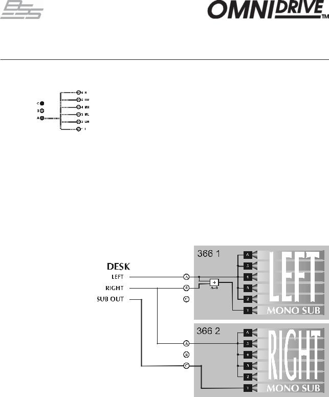
Stereo 3-Way with mono sub-bass.
The FDS-366T has three inputs: A, B, C. An internal mono sum of inputs is also available for routing to any of the outputs. Many combination of routing inputs to outputs is available, and the FDS-366T can be configured as a stereo or mono device. The basic configurations are selected in the Utilities and the following examples are based upon these as possible likely setups.
Systems can be run in one of two stereo 3-way modes.
LLMMHH allows compatability with the 355, now having two low outputs.
LMHLMH set up is an alternative, allowing users to choose the setup they are most familiar with.
Stereo Link "On" mode allows the same parameters on the left and right channels to be adjusted simultaneously, and any edits made whilst unlinked preserve the left/right difference as an offset.
Note: The stereo pairs change appropriately for LLMMHH and LMHLMH modes.
- 16 -
FDS-366Tj
Typical Applications
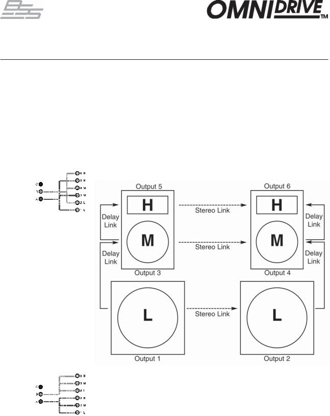
Triple Bi-amp (Stage monitors)
LCR cinema systems (3x2-way)
6-Way zoning distribution
The FDS-366T can provide 3 channels of bi-amp crossover for monitor racks with EQ, delays, and limiters. With so much EQ available in the FDS-366T, it is easy to assign 12 bands of EQ to the input, as well as EQ to the output bands, saving the need for external EQ.
In LHLHLH mode by default, input A feeds outputs 1 and 2, input B feeds outputs 3 and 4, and input C feeds outputs 5 and 6.
In this mode, it is possible to remove ‘hot spots’ on stage. Where the same mix is sent to a number of performers, interaction between wedges can create lobes of high intensity sound causing confusion. Using a fine delay to shift wedge feeds can move these 'hot-spots' to less sensitive areas on stage.
A similar configuration to the triple 2-way setup above.
The FDS-366T can be also be used as a zone distribution system, without using any of its crossover facilities. Using this mode, a common input signal can be routed to up to 6 separate outputs, each with delays, EQ and limiters.
Typical uses for this mode would include feeding a number of under-balcony loudspeakers with integral passive crossovers, using the delays of the FDS366T for time correction, and EQ for tuning response.
For this application set the configuration to Mono and each output should be full range (unless you particularly want to band restrict the outputs). Use the 'Xover Freq' screens in the output channel to set each band edge to be 'OUT'.
- 17 -
FDS-366Tj
Typical Applications
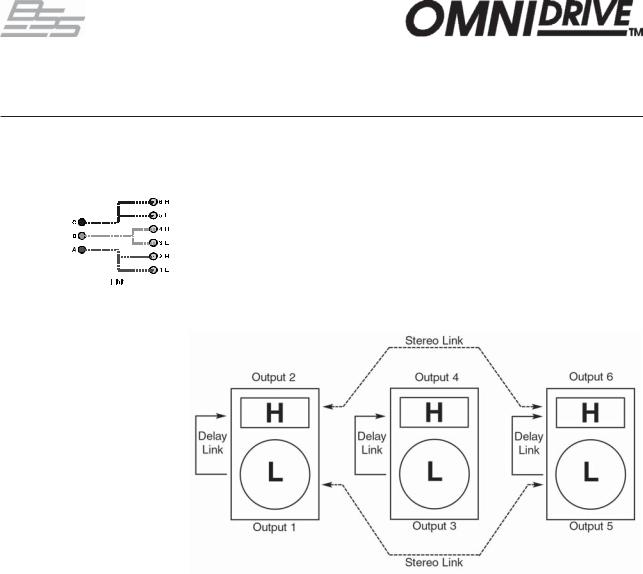
Mono 6-way
Stereo 6-way
(example)
In the mono mode, the FDS-366T can provide a full 6-way system. It can also function as a 5-way system fed from input A, with an independent sub-bass output fed from the sum of inputs A & B or input C.
Two FDS-366Ts working in this mode can form a stereo 6-way system. For example purposes only, in the diagram below the first FDS-366T is running a 5 way system with the mono sub bass derived from the sum of inputs A and B. The second FDS-366T has its mono sub bass output fed from a dedicated output on the desk running into input C.
- 18 -
FDS-366T
7.0Crossover Shapes and Frequencies
It is not possible to provide one loudspeaker driver to cover all audible frequencies. Even if the frequency response could be achieved, the large size of the driver required to shift enough air at low frequencies would offer an impossibly directional beam at high frequencies because at small wavelengths, the differing path lengths from the extremities of the diaphragm to the listener would cause cancellations off-axis. Therefore, it is necessary to use more than one driver and to split the bands with an electrical filter or crossover. This filtering can be done by passive, active or digital means, external to or within the loudspeaker cabinet.
Ideally, the filtering is done so that when acoustically combined, the drivers produce a constant output across the required range of frequencies. Additionally, the signal phase behavior with frequency should offer smooth transitions across all the drivers to achieve a constant group delay. Another important consideration is that the crossover should control the beaming properties, also known as the polar response, so that listeners off-axis do not hear anomalies in the sound range. Many crossover filter designs do not achieve these goals.
Finally, the signal should be quickly attenuated outside the optimum band of operation for each driver to avoid driver anomalies such as resonance and over-excursion distortion at low frequencies. In these instances some crossover shapes have limitations.
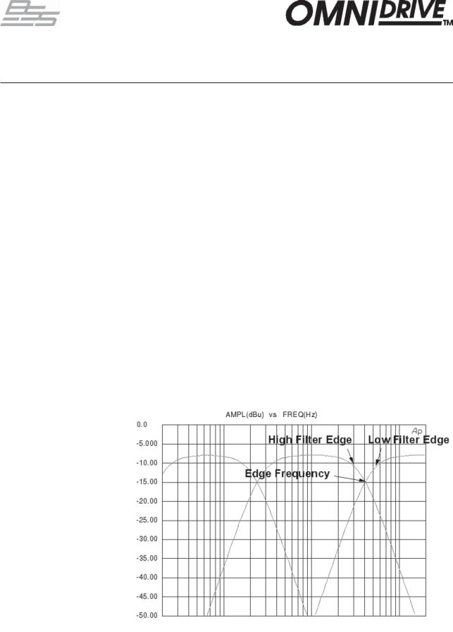
The FDS-366T allows full control over each high and low pass filter of a crossover segment in shape, slope and frequency. Graphically these parameters are labelled as below.
Filter Edge Identification
- 19 -
FDS-366T
Crossover Shapes and Frequencies
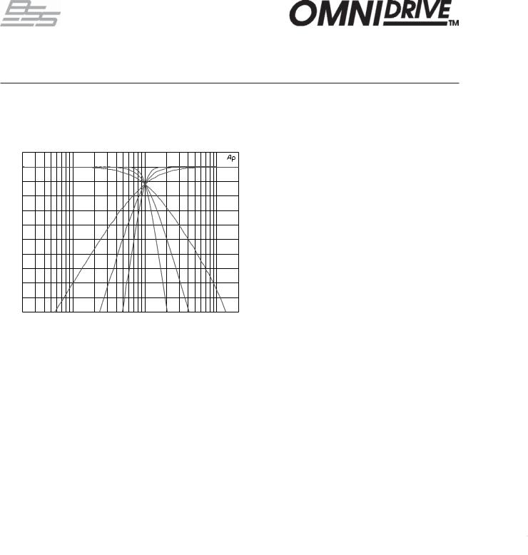
The graphs on this page show the filter slope curves with associated crossover points in order to aid the sound technician in the choice of filter shape to use for the desired result between speaker drivers of differing specifications and characteristics.
5.0000 |
|
|
|
|
0.0 |
|
|
|
|
-5.000 |
|
|
|
|
-10.00 |
|
|
|
|
-15.00 |
|
|
|
|
-20.00 |
|
|
|
|
-25.00 |
|
|
|
|
-30.00 |
|
|
|
|
-35.00 |
|
|
|
|
-40.00 |
|
|
|
|
-45.00 |
|
|
|
|
-50.00 |
|
|
|
|
20 |
100 |
1k |
10k |
20k |
Linkwitz-Riley 12, 24 & 48dB/Octave Slopes.
For many years Linkwitz-Riley crossovers have been the 'industry standard' as they offered the best compromise between the parameters discussed earlier. They retain good polar response, sum to a flat amplitude response and retain correct polarity across the 24dB/octave and 48dB/octave slopes. The 12dB/octave variant generally needs a polarity inversion to achieve the required results. They have been the usual choice for most applications.
Butterworth 6, 12, 18, 24 & 48dB/Octave Slopes.
The even order Butterworth crossovers (12, 24, 48dB/octave) exhibit a symmetrical polar response due to identical phase responses in the Hi and Lo bands. There is an issue with a 3dB peak in the amplitude response at the crossover frequency but this can be corrected with equalisation. In contrast, the odd order Butterworths (6 & 18dB/ octave) sum to a flat amplitude response but suffer asymmetry in their polar response that changes as the signal moves through the crossover point. This 'tilt' can produce colouration and is dependant on the listening position. These also require polarity inversion for correct response.
Bessel 12 & 24dB/Octave Slopes.
Standard Bessel filters when used for crossover duties do not provide immediately acceptable results due to deficiencies in their amplitude response. Due to this only 4th and 2nd order (Bes 24 & 12) alignments were considered to be acceptable for inclusion. The 12dB/octave version will require a polarity inversion of one band for proper summation.
5
0
-
-
-
-
-
-
-
-
-
-
- 20 -
FDS-366T
Crossover Shapes and Frequencies
WHISEWORKS-NTM
Crossover
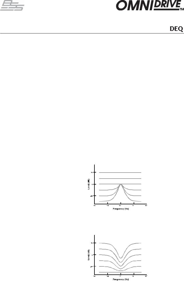
The WHISEWORKS-Neville Thiele Method (NTM) crossover filter is a new type of electrical/acoustical filter offering significant performance advantages over all previous crossover filter types in audio applications. The filter was developed by Neville Thiele (pronounced “Teel”).
This filter uses a unique notched response to achieve a very steep roll-off rate outside the passband. There are two choices of NTM crossover included in the FDS-366T; a 4th order (NTM 36) and an 8th order (NTM52). The 4th order shape offers exceptional group delay flatness with a roll-off of at least 36dB/ octave. The 8th order version offers the steepest roll-off rate of all.
|
10 |
Thiele 4 rolloff |
|
|
|
|
|
|
0 |
|
|
|
10 |
|
|
dB |
20 |
|
|
|
30 |
|
|
|
40 |
|
|
|
50 |
1 103 |
1 104 |
|
100 |
||
|
|
Hz |
|
WHISEWORKS-NTM Crossover Filter advantages:
1.It sums to give constant output against frequency.
2.It has a well defined phase response.
3.It keeps the phase difference between adjacent drivers at zero degrees throughout the crossover region to prevent beam shifting.
4.It has the highest known rate of attenuation in the stop band of all conventional analogue or analogue-equivalent filters of similar order.
The faster roll-off rates realised by the NTM filter shape enable lower distortion that is particularly valuable in applications where space is at a premium as smaller drivers may be used. Driver and cabinet design constraints are also eased since designers can work ‘closer to the edge’ where resonance, breakup, or other anomalies may normally occur with more gentle slopes.
The new Neville Thiele Method crossover shapes now represent the optimal combination of characteristics for most applications and listening tests seem to bear this out! We feel that this shape could topple the Linkwitz-Riley as the new 'industry standard', particularly as the nearest Linkwitz-Riley equivalent (L-R 48) has attained a reputation for a "hard sound", this doesn't appear to be the case using the NTM shapes.
- 21 -

FDS-366T
Crossover Shapes and Frequencies
Crossover comparison chart
Below is a chart comparing the different crossover filter types that are provided in the FDS-366T Omnidrive. This table should help to ascertain the particular choice of filter dependant on application. Shapes marked with an asterisk * will require polarity inversion.
Key:
•= Worst
••••••= Best
BUT = Butterworth BES = Bessel
L-R = Linkwitz-Riley NTM = Neville Thiele Method
Amplitude response flatness: also known as 'frequency response', a measure of the flatness of the amplitude with differing frequencies. Choosing a crossover alignment that sums to a flat amplitude response is usually desirable because such a system will require less equalisation.
Group delay flatness: a measure of how different frequencies are delayed throughout the crossover region. Although it is unlikely that all frequencies can be delayed equally, a smooth group delay response that lacks peakiness is desirable.
Polar response: a qualification of the lobing effect due to the distance between any pair of drivers involved in the crossover. The main lobe needs to be onaxis so that listeners on-axis do not hear dips in the amplitude response through the crossover region.
Roll-off rate: A measure of how quickly the slope of the filter drops off to a much lower amplitude. A steeper slope is generally required to maximise the potential of driver frequency response and to narrow the frequency range that is affected by the crossover operation.
- 22 -

FDS-366T
Crossover Shapes and Frequencies
Phase
Compensation
Phase compensation to active crossovers was introduced in the classic FDS355 Omnidrive Compact Loudspeaker Management System. The FDS-366T Omnidrive includes this feature, freeing the user of worry about phase alignment between bands.
More info about Phase Compensation:
A properly designed 2 way crossover always exhibits the inter-band phase relationships that are characteristic of the chosen crossover shape. For example, the Linkwitz-Riley filter shape, with its low-pass filter for the low band, and high-pass filter for the high band, will maintain zero phase difference between these bands at all frequencies, which means that the acoustic outputs from the drivers will sum to a flat response, free of any shifting in polar response.
In 3 way (or more) systems, things can start to go wrong. The mid band in a 3 way system for example, has not one filter, but two (high-pass, and low-pass). The low-pass filter, set at the mid-high crossover frequency will produce some phase disturbance at the low-mid crossover frequency, causing the low-mid crossover filter pair to be misaligned. The same is true of the high-pass filter, which may affect the mid-high crossover filter pair. This misalignment causes incorrect acoustic summing, which results in a non-flat response, and a polar response which shifts with frequency, causing further response problems in some listening positions. Although these effects may be subtle when the crossover frequencies are well separated, 4 and 5 way systems particularly can produce significant errors.
The phase compensation scheme employed in Omnidrive analyses these phase anomalies whenever adjustments are made, and automatically introduces phase adjustment into certain bands so that the phase difference between adjacent bands is always close to zero degrees. Intentional phase differences can be introduced using the Delay and Phase parameters.
Omnidrive will not attempt to apply phase compensation if the high and low frequencies or shapes of the adjacent bands do not match, on the assumption that the user does not expect to produce a standard crossover alignment.
By default the FDS-366T applies phase compensation to crossover setups where there are 3 bands, or more, in use on a channel and where the crossover filter shapes are identical. In general the application of this feature is desirable to maintain the correct phase relationships between bands but, in certain circumstances phase compensation may need to be defeated to avoid phase inconsistencies between separated speaker installations, such as side or under fills and certain monitoring applications. The facility to do this is called 'Phase Comp' and is found in the Utilities.
- 23 -
FDS-366T
8.0 Dynamic Equalisation
What is DEQ? The BSS DPR-901 Analogue Dynamic Equaliser was a revolutionary way of dealing with equalisation, and was made possible by the subtractive
progressive knee technique developed for the industry-standard DPR-402 Analogue Compressor. The very same techniques are used in the FDS-366T to give you dynamic control of equalisation, or indeed for conventional full-range compression on every input and every output.
The compressor used in the FDS-366T Dynamic Equaliser uses the audibly transparent ‘subtractive VCA' (Voltage Controlled Amplifier) technology used in all other BSS compressors, and results in substantially better performance than other methods. There is clearly no VCA in use in the FDS-366T, as it is a digital device, but the DSP (Digital Signal Processing) models the effect using algorithms developed by our crack team of audio systems experts.
The subtractive ‘VCA’ also allows the realisation of a completely different type of compression that BSS have named parametric compression. This enables selective compression to be applied to only certain frequencies in a signal, as displayed by a conventional looking parametric filter control window. When the selected frequencies are encountered, the Dynamic Equaliser starts to compress only those signals at a rate determined by the ratio and threshold controls.
The Dynamic Equaliser operates in two very different ways depending on whether the parametric equaliser is set to boost or cut:
In boost mode, the parametric equaliser is allowed to impose its response on the signal when below threshold, but the effect of the equaliser is ‘flattened out’ as the signal starts to exceed threshold.
Dynamic EQ boost at -15dB threshold
In cut mode however, the equaliser only has effect above threshold, and is flattened out as the signal reduces below threshold.
Dynamic EQ cut at -15dB threshold
- 24 -

FDS-366T
Dynamic Equalisation
Notes and Uses Frequency selective compressing
Conventional compressors affect the whole audible band of frequencies equally. Some compressors can be configured to only start compression when they encounter given frequencies, however, once they start compressing they compress the whole audio band. This is quite distinct from the type of compression available in the FDS-366T DEQ.
The DEQ can be set up so that when it encounters a given band of frequencies it compresses only that band, this is a very different technique from simple equalisation and is vastly more powerful for both corrective applications and creative manipulation.
To use Dynamic EQ as a wide band compressor, use high pass (i.e low shelving) with a low frequency or vice versa.
Use with Stereo sources
To avoid 'image shift' when stereo sources are compressed the input DEQs have their sidechains linked when the Stereo Link parameter is set to "On" .
Control of horn distortion
Above a certain critical sound level output, horn loaded speakers often start to produce distortion. This is due to the irregular movement of air in the horn throat and is usually a problem over a restricted range of frequencies. The band of frequencies affected is dependent on the dimensions of the horn.
The DEQ can be used to reduce the energy in the frequency band that aggravates the horn, resulting in both a much-improved sound and the possibility of higher sound levels.
To do this:
1With some program material playing, set the EQ shape of the DEQ to Bell with some boost.
2Manipulate the sound system level, DEQ frequency and width parameters to find the frequency band that is causing problems.
3Make this band as narrow as possible using the width parameter, ensuring that the DEQ is initially set to "Off".
4Set the EQ to cut and increase the system sound level until there is unacceptable distortion.
5Adjust the threshold ("Thr") parameter until the distortion is diminished.
6Try different ratio and filter settings to achieve the best response.
- 25 -

FDS-366T
Dynamic Equalisation
Dynamic bass and treble enhancement
The bass and treble content of the program can be made to appear louder without increasing the overall sound level if the middle frequencies of the program are reduced when the sound level approaches the limit. This can be especially useful to squeeze the last few dB of perceived headroom out of a PA.
The parametric equaliser associated with the Dynamic Equaliser is much like the other EQs in the FDS-366T (and may in fact be used as a conventional equaliser if DEQ is set to "Off".
As the sidechain of the compressor is fed from the equaliser, this endows the DEQ with the unique ability to select a portion of the audio band and compress only that band.
To do this:
1Set the EQ parameters to boost at the appropriate frequencies, using either BELL filter shape, or probably more aptly, LO-SHELF for the LF end or HI-SHELF for the HF end.
2Set the threshold ("Thr") parameter so that the boost/cut bargraph starts to go upward at the desired level.
3Adjust the ratio control for the correct amount of compression.
For more information on setting Dynamic Equalisation please refer to the DEQ descriptions in the Input and Output sections of this manual.
- 26 -

FDS-366T
The Rear Panel
and Connections
- 27 -
FDS-366T
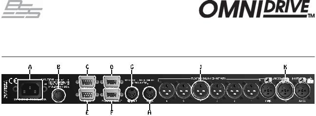
9.0Rear panel
A Mains power input
The power inlet for the FDS-366T. Note that there is no On/Off switch for the unit. Accepted voltage range: 90-240V AC 50/60Hz, autosensing.
B Fuse
In the event of failure due to mains overload only replace with T1A fuse as stated on the unit.
C,D RS-485 connectors
Serial connection to a PC on a multi-drop network.
E RS-232 connector
Serial connection to either a PC or to connect to another FDS-366T.
Provides an easy way to upload new software.
F Program select connector
Use to select programs 1-8 with external switches or buttons or can also be connected to Soundweb's control port logic outputs.
GMIDI OUT connector
HMIDI IN connector
For connection to other FDS-366T units in order to perform simultaneous program changes, backup or control functions.
J Band outputs (6)
The FDS-366T audio outputs are electronically balanced and floating.
Pin 1 |
Shield/Ground |
Pin 2 |
Signal Hot (+) |
Pin 3 |
Signal Cold (-) |
K Channel inputs (3)
The FDS-366T audio inputs are electronically balanced. Transformer balancing is available as a retrofit option.
Pin 1 |
Open circuit |
Pin 2 |
Signal Hot (+) |
Pin 3 |
Signal Cold (-) |
- 28 -

|
|
FDS-366T |
10.0 Connections - Mains Power |
, |
|
Mains Power IMPORTANT: The wires in the mains lead are colour coded in accordance |
||
with the following code. |
|
|
|
|
|
|
Green and Yellow = Earth |
|
|
Blue = Neutral |
|
|
Brown = Live |
|
|
|
|
If the colours of the wires in the mains lead do not correspond with the identifying markings on the terminals in your plug refer to the following:
The wire that is coloured Green & Yellow or Green must be connected to
the terminal which is marked with the letter ‘E’ or by the Earth symbol  or which is coloured Green & Yellow or Green.
The wire that is coloured Blue must be connected to the terminal labelled ‘N’ or coloured Black or Blue.
The wire that is coloured Brown must be connected to the terminal labelled ‘L’ or coloured Red or Brown.
WARNING! THIS APPLIANCE MUST BE EARTHED.
The Green and Yellow wire of the mains cord must always be connected to an installation safety earth or ground. The earth is essential for personal safety as well as the correct operation of the system, and is internally connected to all exposed metal surfaces. Any rack framework into which this unit may be mounted is assumed to be connected to the same grounding circuit.
”Units supplied to the North American market will have a moulded 3 pin connector that is provided to satisfy required local standards.
Voltage setting The FDS-366T uses a switch mode power supply which offers high efficiency and low heat generation. This power supply accepts universal AC power input voltages in the range 100V AC to 240V AC (nominal), and requires no setting adjustment for AC power voltages in this range. Minimum AC input voltage is 90 Volts, and the maximum is 264 volts.
Outside these ranges the unit will not work satisfactorily, if at all. Voltages in excess of the maximum will probably cause damage. Voltages below the minimum will cause complete system shutdown. The flash memory in the unit should preserve all data in the event of a power failure.
- 29 -

|
FDS-366T |
|
Connections - Mains Power |
, |
|
|
|
|
AC Power fusing The incoming mains power is protected within the FDS-366T by a fuse in the holder mounted on the rear panel.
In the event that a mains fault occurs and blows this fuse always replace with an identical 20mm x 5mm 'T' fuse, rated at 1A for continued protection from equipment damage and fire.
Spare fuses of the correct rating are supplied with the unit.
It is most important for continued safety that this specification is strictly adhered to.
Location of mains fuse on rear panel.
- 30 -
 Loading...