

Page 1
FDS 360
User Manual
1
Page 2

V3.0 JMK 14 October 1996
This equipment has been tested and found to comply with the following European Standards for
Electromagnetic Compatibility:
Emission Specification: EN55013 (1990) (Associated equipment)
Immunity Specification: EN50082/1 (1992) (RF Immunity, Fast Transients and ESD)
Mains Disturbance: EN61000/3/2 (1995)
For continued compliance ensure that all input and output cables are wired with cable screen connected to Pin
1 of the XLR. The input XLR Pin 1 on BSS equipment is generally connected to chassis via a capacitor to
prevent ground loops whilst ensuring good EMC compatibility.
We have written this manual with the aim of helping installers, sound engineers and consultants alike get to
grips with the FDS-360 and obtain its maximum capability.
If you are new to BSS products, we recommend that you begin at the start of the manual. If, however, you are
already familiar with the intended application, and just want to get the unit installed without delay, then
follow the highlighted sections.
We welcome any comments or questions regarding the FDS-360 or other BSS products, and you may contact us
at the address or World Wide Web site given in the warranty section.
2
Page 3
Contents
Contents
1. 0 What is a Crossover? 5
2. 0 The difference between Active and
Passive Crossovers 6
3.0 Other advantages 7
4.0 The Linkwitz-Riley advantage 8
5. 0 What is special about BSS
Crossovers? 9
6.0 Unpacking 9
7.0 Mechanical Installation 12
8. 0 Mains Power Connection 1 3
9. 0 Input Connections 1 4
9.1 XLR Plugs. 14
10.0 Output Connections 14
10.1 XLR Plugs 14
11.0 Controls 16
11.1 Mode Switch 16
11.2 Level Control 16
11.3 Mute Switch 16
11.4 Polarity Switch 17
11.5 Mono Low Switch 17
11.6 Phase Control 17
11.7 Limiter Threshold Switch 18
11.8 Signal LEDs 18
12.0 Frequency Cards 19
Card Location for Four Way System 19
Card Location for Three Way System 19
Card Location for Stereo Two Way System 19
13.0 Rear Barrier Strip 20
13.1 Limiter Cancel 20
13.2 Auto Mute Cancel 20
13.3 Limiter Threshold Reference 20
13.4 Band Insertion Points 20
3
Page 4

Contents
14.0 Modes of Operation 2 1
14.1 Mono Three Way with Extra Full Range
Buffered Output 21
14.2 Operating a Sub-Woofer system from an
Effects Send 21
14.3 Mono Low between separate units 21
15.0 Limiter Adjustment 22
Adjustment for A 22
Adjustment for B 22
16.0 Phase Adjustment 24
17.0 System Diagrams and Descriptions 2 5
17.1 Full unit 25
17.2 15Hz Subsonic Filter Change 25
18.0 Filters and Frequency Tables 2 7
18.1 Standard Filters 27
18.2 Full Range Frequency Card 27
19.0 BSS Supported Options 30
19.1 Output Balancing 30
19.2 Security Cover 30
20.0 FDS-360 Equalisation Options 31
20.1 Introduction 31
20.2 FDS-360D Installation 31
20.3 Circuit Description 31
20.4 Filter Design 33
20.5 Application Notes 35
20.6 Application of the FDS-360D to a system 36
20.7 FDS-360 E Installation 38
21.0 Electronic/Chassis Earth Link 39
22.0 Transient Suppressor Replacement 39
23.0 Troubleshooting 40
24.0 Glossary 41
25.0 Specifications 44
26.0 Warranty Information 45
Index 49
User Notes 51
4
Spare Parts Information
Page 5
1.0 What is a Crossover?
Crossovers are a necessary part of sound reinforcement systems because the
loudspeaker drive-unit which can produce clear reliable high SPL (sound
level) over the full audio bandwidth has yet to be invented. All real-world
drive units work best when they are driven over a limited band of frequencies,
for example: Low, Mid and High.
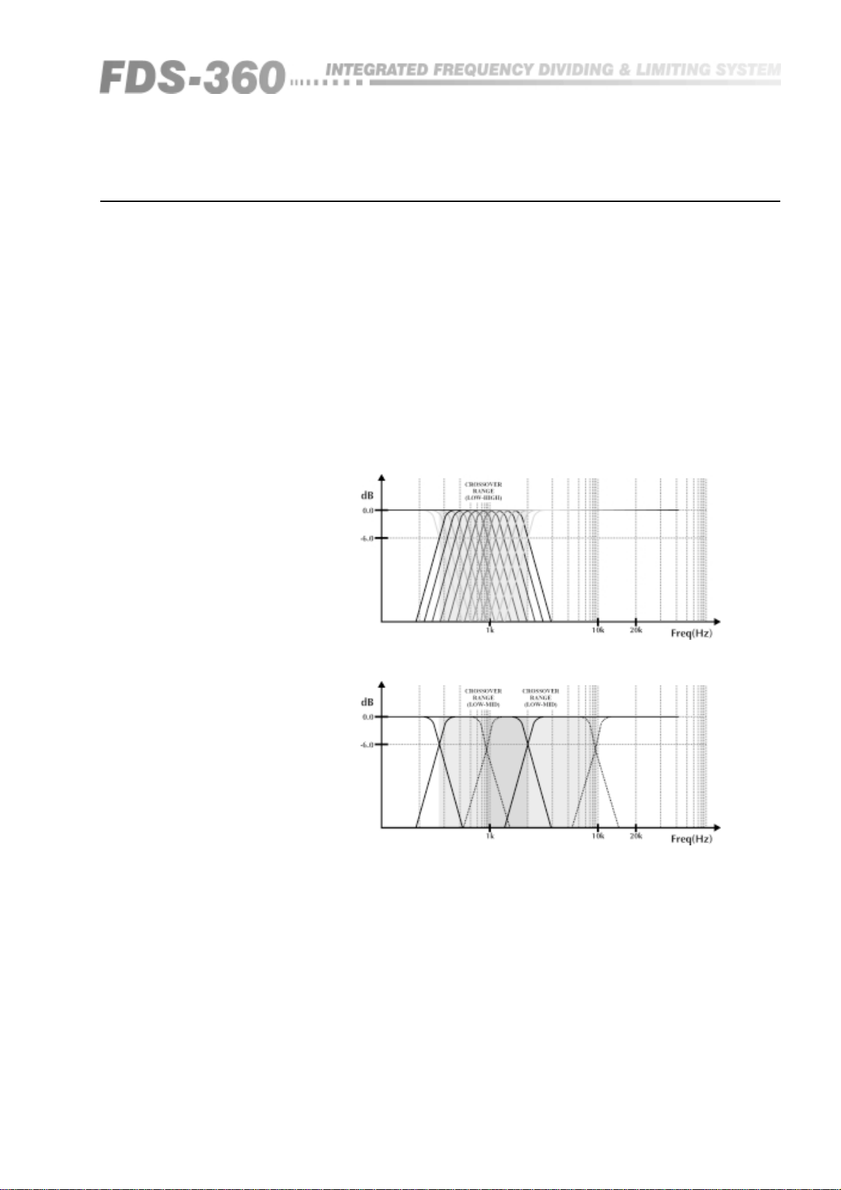
Any crossover aims to provide the division of the audio band necessary, so
each drive unit receives only the frequencies it is designed to handle. In a
high power, high performance sound system, the crossover should also reject
unsuitable frequencies to avoid damage and poor quality sound.
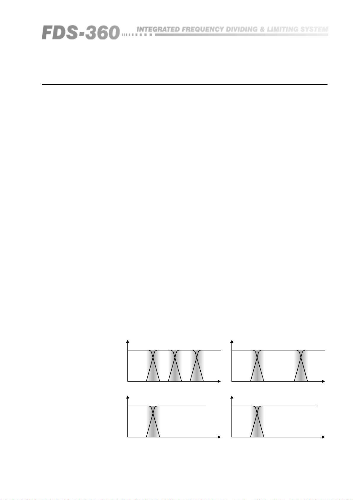
Fig 1.1 Stereo 2-way
Crossover setup
Crossovers
Fig 1.2 Mono 3-way
Crossover setup
5
Page 6
Active and Passive Crossovers
2.0 The difference between Active and
Passive Crossovers
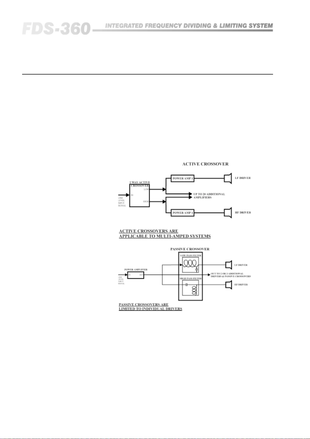
Passive crossovers divide the frequency spectrum after the signal has been
raised to a high power level. They are generally heavy, bulky and inefficient.
Active crossovers utilise ICs and transistors, and divide the frequency
spectrum at line levels, immediately ahead of the amplifiers (See Figure 2.1).
An active crossover does the same job as a passive crossover, but with more
precision, flexibility, efficiency, and quality.
Fig 2.1
• Crossover frequencies can be more readily altered to suit different driverhorn combinations.
• The level balance between the 2 or 3 frequency bands (brought on by
differences in driver and amplifier sensitivity) can be readily trimmed.
• Inside an active crossover unit, line-driving, signal summing, driver
equalisation, system muting and polarity ('phase') reversal facilities can all be
incorporated at small extra cost.
6
Page 7
3.0 Other advantages
The drive-units in sound reinforcement systems utilising active crossovers
benefit because:
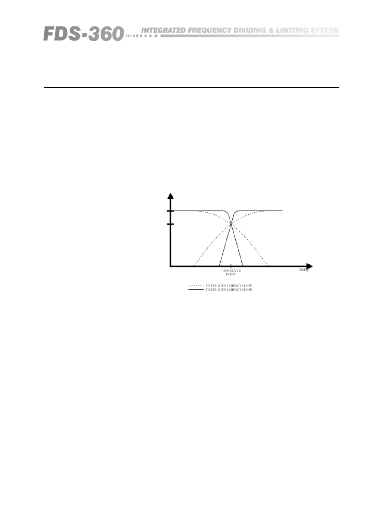
• Steep rolloffs are readily attainable. The -24dB/OCT rolloff in the BSS FDS-
360 active crossover rapidly discharges out-of-band energy. At one octave
below the crossover point power received by the driver has dropped to less
than ½% (or 1/200th) of full power. The result: Bad sound resulting from out-
of-band resonances are effectively masked immediately beyond the crossover
frequency (See Figure 3.1). This contrasts markedly with passive crossovers,
where slopes in excess of -12dB/OCT are rarely achieved, and power rolloff is
4 times less rapid, per octave.
Fig 3.1 Crossover
Terminology
Crossover advantages
• If one frequency range is driven into clip, drive-units and horns in other
frequency ranges are protected from damage, and distortion is kept to a
minimum.
• Direct connection of drive-units to the power amplifier cuts out loss of
damping factor, normally inevitable thanks to the appreciable resistance of
the inductors in passive crossovers.
Amplifiers benefit too from the use of active crossovers. Because they do not
handle a full-range signal, clipping produces far less harmonic and
intermodulation distortion. The results: Momentary overdrive sounds less
harsh. Also the amplifiers' dynamic headroom is generally higher, and
heatsink temperatures can run lower.
7
Page 8
Linkwitz-Riley Alignment
4.0 The Linkwitz-Riley advantage
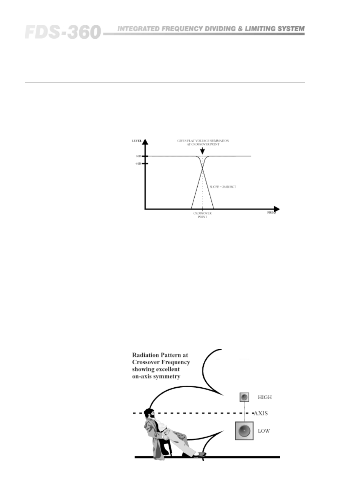
There is an additional set of advantages exclusive to active crossovers made
by BSS, and other manufactures using the Linkwitz-Riley alignment (See
Figure 4.1).
Fig 4.1 Linkwitz-Riley
filters
Fig 4.2 Radiation
Pattern Frequency
showing excellent on-
axis symmetry
Zero Phase difference at crossover: The phase difference between drivers
operating in adjacent frequency bands is close to zero degrees at the
crossover frequency.
'Phase alignment' in this manner prevents interactive effects (i.e.: High and
Low drivers 'fighting' each other), over the narrow band of frequencies around
the crossover point; this is where the units from two adjacent frequency ranges
are contributing near equal amounts of sound pressure.
More predictable sound dispersion: By providing in-phase summation at the
crossover point(s), the Linkwitz-Riley alignment provides for more cogent
sound dispersion - it provides on-axis symmetrical radiation patterns. (See
Figure 4.2).
'Invisible' slopes: The absence of electrical phase difference close to the
crossover frequency helps to make the steep -24dB/OCT slope effectively
inaudible,. Response peaks and dips are negligible and inaudible given the
correct polarity ('phasing') of the speaker connections. The same is not true of
the shallower (-6, -12 or -18dB/OCT) rates or rolloff, in other crossovers.
8
Page 9

BSS Crossovers
Unpacking
5.0 What is special about BSS Crossovers?
The FDS-360 is an electronic crossover system, and incorporates all the latest
technology and facilities that are required for todays high powered
loudspeaker systems. This frequency dividing system (FDS) is substantially
more than a basic crossover, combining a high degree of sophistication which
enables accurate control of loudspeaker power, dispersion and acoustical
summation around the critical crossover region.
The FDS-360 features the following:
• Stereo two-way mode, or switchable three/four way mono mode.
• Separate frequency band limiters matched to the precise band of
frequencies controlled.
• Separate polarity switching for each band.
• LED signal level monitoring.
• Band insertion points for interfacing external equalisation and time delay
units.
• Band-edge phase adjustment allowing 360 degrees of control.
• Crossover filter programming via plug-in frequency cards allowing any
frequency, choice of 12/18/24dB/OCT slopes and filter responses to be
specified. 24dB/OCT Linkwitz-Riley responses are supplied as standard.
• Internal equalisation option.
Every FDS-360 is manufactured to the highest professional standards with a
robust steel case, high quality circuit boards and ICs, and high quality
components to provide reliable performance under the most demanding
conditions of the global sound-reinforcement environment. In common with
all other BSS equipment, the FDS-360 is subject to stringent quality control
procedures throughout the manufacturing process. Components are tested
against demanding acceptance criteria. Every completed unit is tested both
by measurement and in a listening test carried out by trained audio
professionals. To positively ensure reliability, all units are burnt-in for fifty
hours, before being tested.
6.0 Unpacking
As part of BSS' system of quality control, this product is carefully inspected
before packing to ensure flawless appearance.
After unpacking the unit, please inspect for any physical damage and retain
the shipping carton and ALL relevant packing materials for use should the unit
need returning.
In the event that damage has occurred, please notify your dealer
immediately, so that a written claim to cover the damages can be initiated.
See Section 26.
9
Page 10
Getting to know the FDS-360
A
A
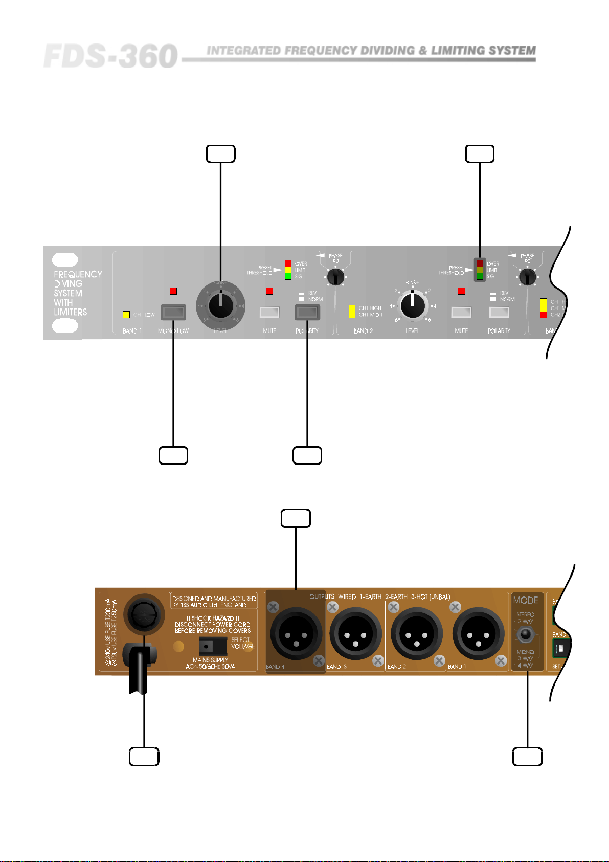
Fig 6.1 Front Panel
11.2
11.8
Fig 6.2 Rear Panel
5x20mm
FUSE
8.0
11.411.5
10.0
ON
.5 1
W
OFF
ON
240
.5 1
OFF
W
11.1
10
Page 11
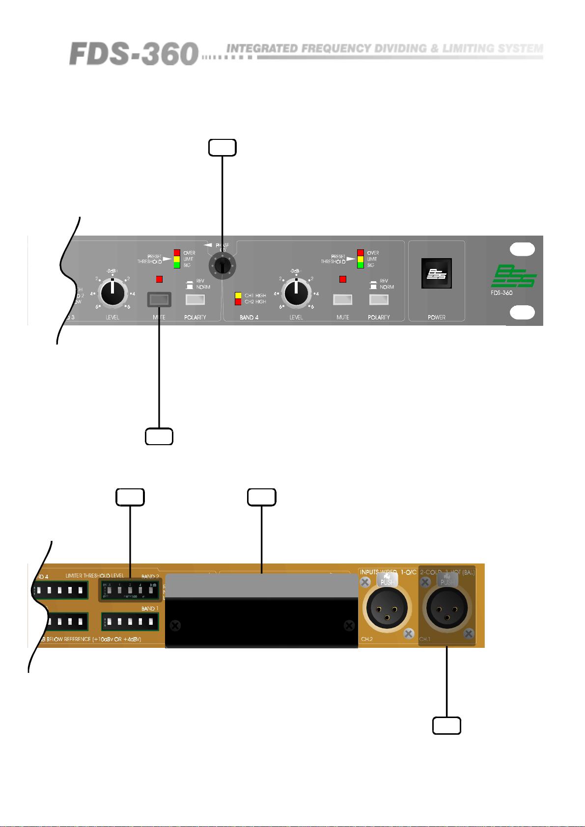
11.6
ON
.51248dB
4H
WATS5 60B
OFF
ON
.51248dB
4H
WATS5 60B
OFF
11.3
11.7 13.0
ON
.51248dB
4H
WATS560B
OFF
ON
.51248dB
4H
WATS560B
OFF
9.0
All numbers in bubbles refer to Section numbers.
11
Page 12
Installation
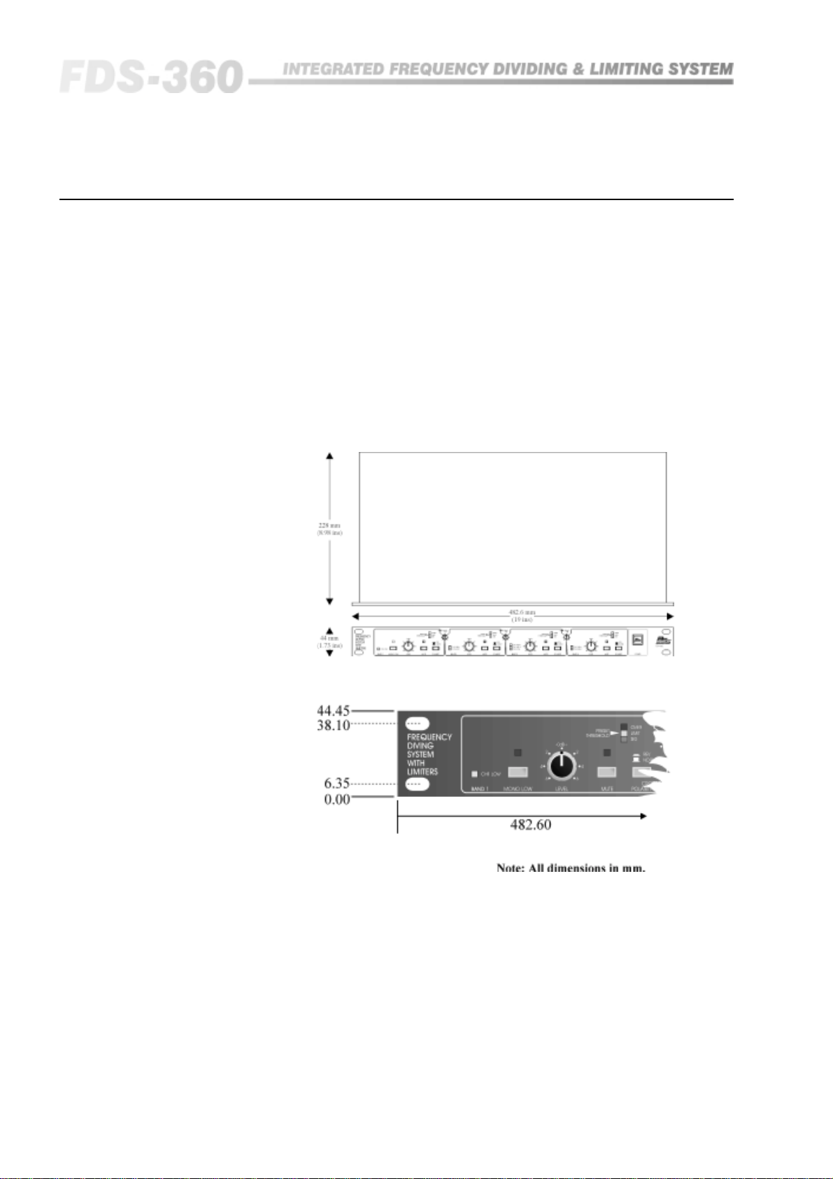
7.0 Mechanical Installation
A vertical rack space of 1U (1¾" / 10½mm) deep is required. Ventilation gaps
are unnecessary (See Figure 7.1).
If the FDS-360 is likely to undergo extreme vibration through extensive road
trucking and touring, it is advisable to support the unit at the rear and/or sides
to lessen the stress on the front mounting flange. The necessary support can
generally be bought ready-built, as a rack tray. As with any low-level signal
processing electronics, it is best to avoid mounting the unit next to a strong
source of magnetic radiation, (for example, a high power amplifier), to help
keep residual noise levels in the system to a minimum.
Fig 7.1 Unit dimensions.
12
Fig 7.2 Rack
dimensions.
Page 13
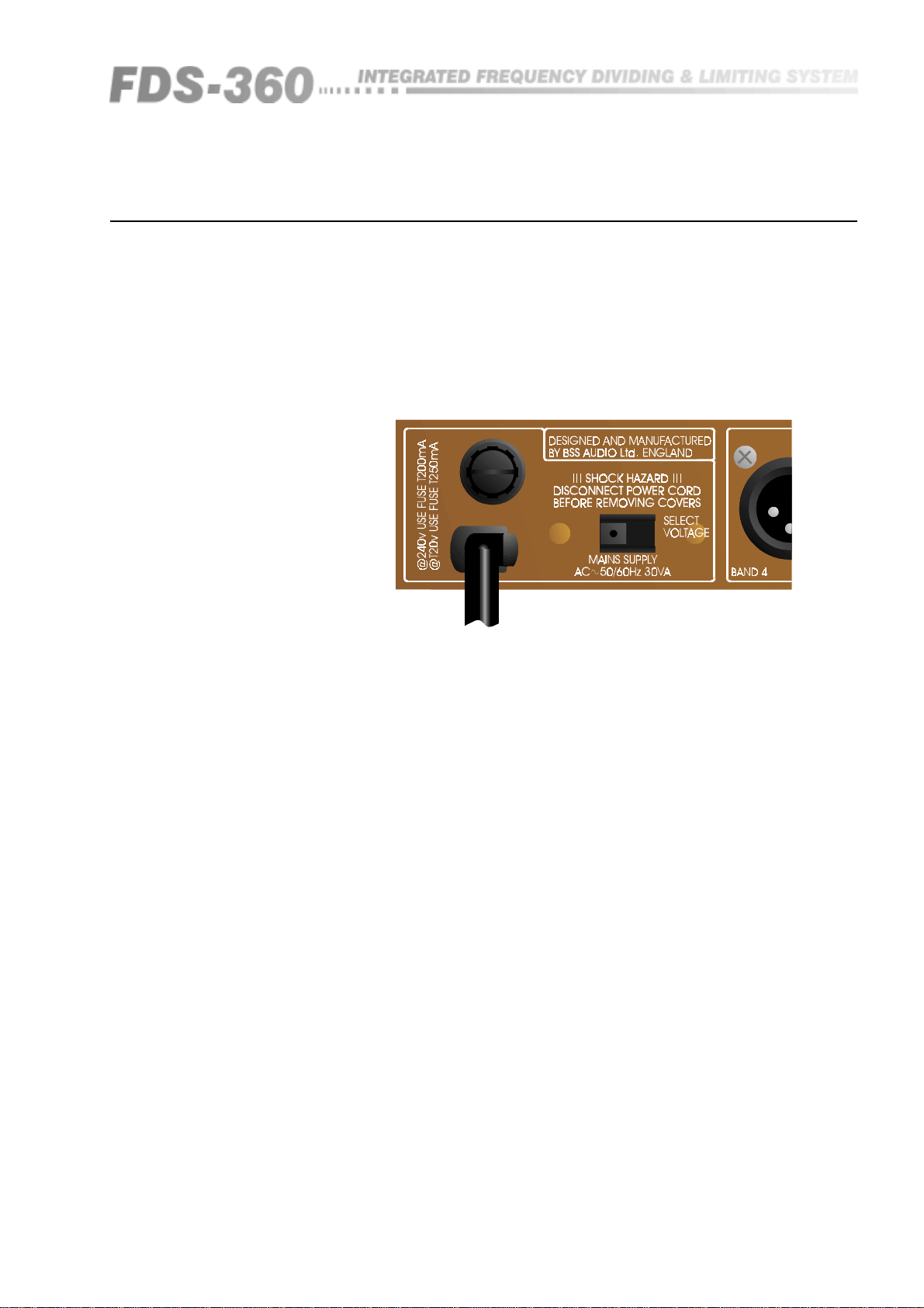
8.0 Mains Power Connection
Voltage: The FDS-360 operates on supply voltages between 95 and 125V AC.
It must not be plugged into 220, 230 and 240V AC outlets. If the unit is
accidentally connected to an AC supply giving in excess of 132V AC, refer to
section 23, (See Figure 8.1).
Frequency: Both 60Hz and 50Hz are acceptable.
Fig 8.1 Mains fuse on
rear panel.
5x20mm
FUSE
Connecting to Power
240
Grounding: The FDS-360 must always be connected to a 3-wire grounded
('earthed') AC outlet. The rack framework is assumed to be connected to the
same grounding circuit. The unit must NOT be operated unless the power
cables ground ('earth') wire is properly terminated - it is important for personal
safety, as well as for proper control over the system grounding. If the
electronic 0V has to be separated from the chassis and mains power earth,
refer to section 23.
Connections: The AC power cable has a moulded 3-pin utility plug attached
to the free end to facilitate the correct and proper connections.
AC Power Fusing: The incoming line power passes through a 200mA (for 240V
only) anti-surge ('T') fuse, accessible from the rear panel (The fuse is rated at
250mA for 120V). If the fuse blows without good reason, refer to section 23.
Always replace with an identical 20mm x 5mm T rated fuse for continued
protection from equipment damage and fire. Also see section 22 for
information on replacing blown transient suppressors (if applicable).
Power ON: Before turning on the power, it is worth checking that the three
frequency cards are installed correctly. Loosen the captive screw securing the
small cover plate on the lid of the unit, and inspect the cards. The slope and
frequency information is recorded on each of these cards, and it must be
ensured that all cards are fitted, regardless of whether they are required. Refer
to sections 12 & 18 for more information concerning these cards.
The FDS-360 outputs are instantaneously muted at power OFF. At switch on, a
delay prevents turn-off thumps propagating through the sound system.
13
Page 14
Input Connections
9.0 Input Connections
9.1 XLR Plugs.
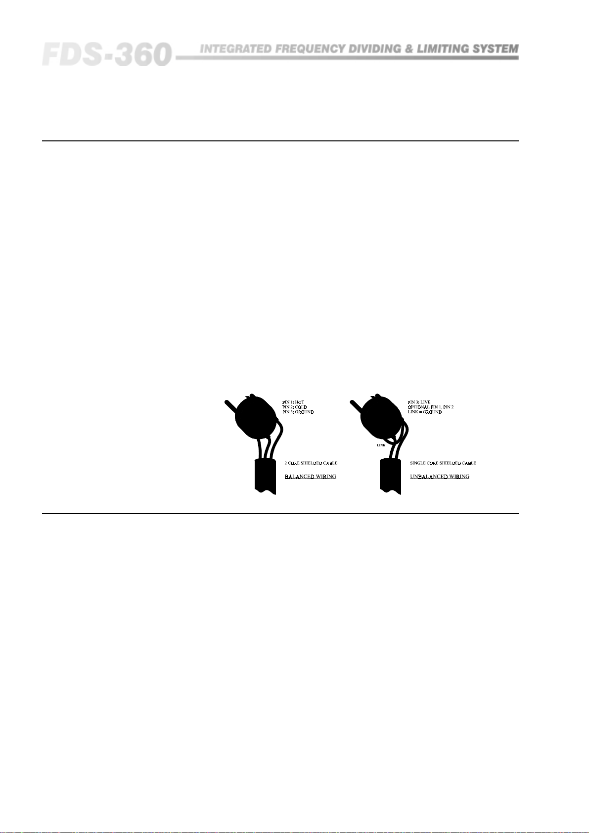
Fig 9.1 XLR Plug Wiring
The two input signals are 10k ohm active balanced on a standard 3 pin
'female' XLR which will accept levels up to +20dBv. The wiring convention is
as follows: (See Figure 9.1a):
Pin 1: No connection (the shield of the drain wire can be terminated
here if desired).
Pin 2: Signal '-', out of phase or 'COLD'.
Pin 3: Signal '+', in phase or 'HOT'.
For unbalanced sources (See figure 9.1b):
Pin 1: Leave open, or link to pin 2.
Pin 2: Shield, braid, or screen wire.
Pin 3: Signal '+' or 'HOT' (inner core).
There is no internal ground connection to Pin 1 of the female XLR to avoid
possible interconnection earth loops. The input signal cable shield must
therefore be tied to ground, or signal 0V, at the source end.
10.0 Output Connections
10.1 XLR Plugs
14
The four signal outputs are DC blocked low impedance unbalanced from a
standard 3 pin male XLR and are designed to drive up to +20dBv into 600
ohms or greater. The wiring convention is as follows:
Pin 1: Connects to shield, screen or drain wire.
Pin 2: '-', cold or 'out of phase' output.
Pin 3: '+', hot or 'in phase' output.
If the amplifiers you are feeding have unbalanced (single ended) inputs, but
are fed from standard pin to pin XLR cables (See above), simply link the cable
at the crossover end as follows:
Pin 1: Connects to shield or screen wire.
Pin 2: Link to Pin 1.
Pin 3: Connects to the inner 'hot' or live core.
Unbalanced transmission is not recommended for connections to distant
equipment, but is generally acceptable for local connections within the rack,
or to an adjacent rack.
Page 15

Output Connections
Technicians note: As with a traditional transformer balanced output, either
output phase (+ or -, hot or cold) can be linked to ground to 'unbalance the
line' without upsetting the operation of the unit. As with a transformer, output
level remains the same in the unbalanced mode.
15
Page 16
Controls
11.0 Controls
11.1 Mode Switch
11.2 Level Control
ON
.5
OFF
ON
240
.5
OFF
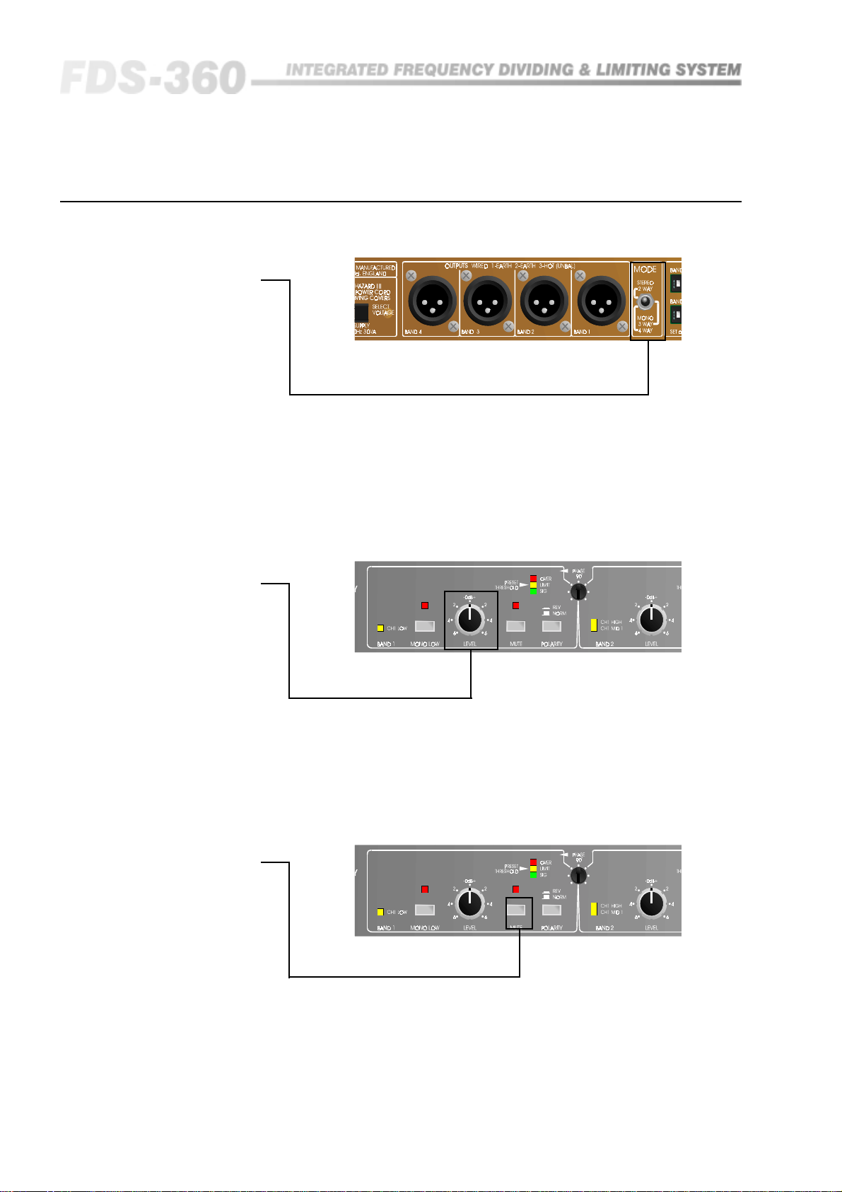
The mode switch is located at the rear of the unit and sets the internal
architecture for either the stereo 2-way, the mono 3-way, or mono 4-way
mode. In the mono modes, the channel 1 input connector is used. Refer to
section 14 for other possibilities.
This selector switch also operates the front panel 'band' LEDs, to give a visual
indication of the function of each of the four frequency bands.
11.3 Mute Switch
16
The four front panel controls adjust the level of the program in each of the
frequency bands, and is set to give a precise restricted range of ±6dB. In their
fully anticlockwise position they do not reduce the level to zero.
These controls are designed to allow the operator to carefully balance the
respective bands in relation to each other, and do not interfere with the
crossover networks, or the limiter threshold settings.
These four controls have a momentary action and allow the operator to mute
each band individually. Pressing once will activate the mute function, and
pressing again will de-mute. In addition, to protect the following speaker
system from DC power thumps, logic circuits ensure that all band outputs are
automatically muted when power is first switched on, or if a DC fault occurs
internally to the unit. This will be noted when first powering up, as the four
mute LEDs will remain on. Refer to section 13.2 for further details.
Page 17
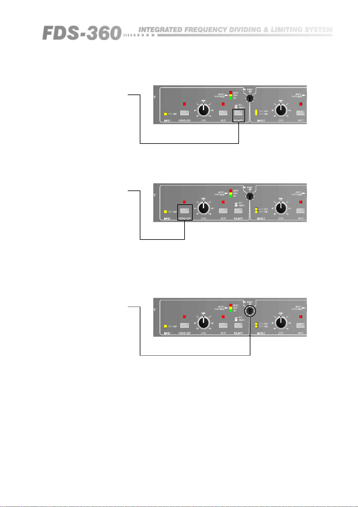
11.4 Polarity Switch
11.5 Mono Low
Switch
These four latching switched allow 180 degree phase reversal of the signal
output for each band individually. Refer to section 16 for more information.
When operating the FDS-360 in the stereo 2-way mode, this switch will sum
together the signal information in bands 1 and 3 so that the outputs of these
bands are equal, regardless of input stereo image. This gives a mono low
signal feed which is often desirable for low frequency information. Refer to
section 14.3 for more information regarding mono low linking.
11.6 Phase Control
These three controls will adjust the relative phase between adjacent band
outputs at the crossover region. The phase circuitry is programmed by the
frequency cards to give precise control regardless of the crossover frequency.
When these controls are used in conjunction with the polarity switch the
operator has a full 360 degree of adjustment. Refer to section 16 for further
information.
17
Page 18
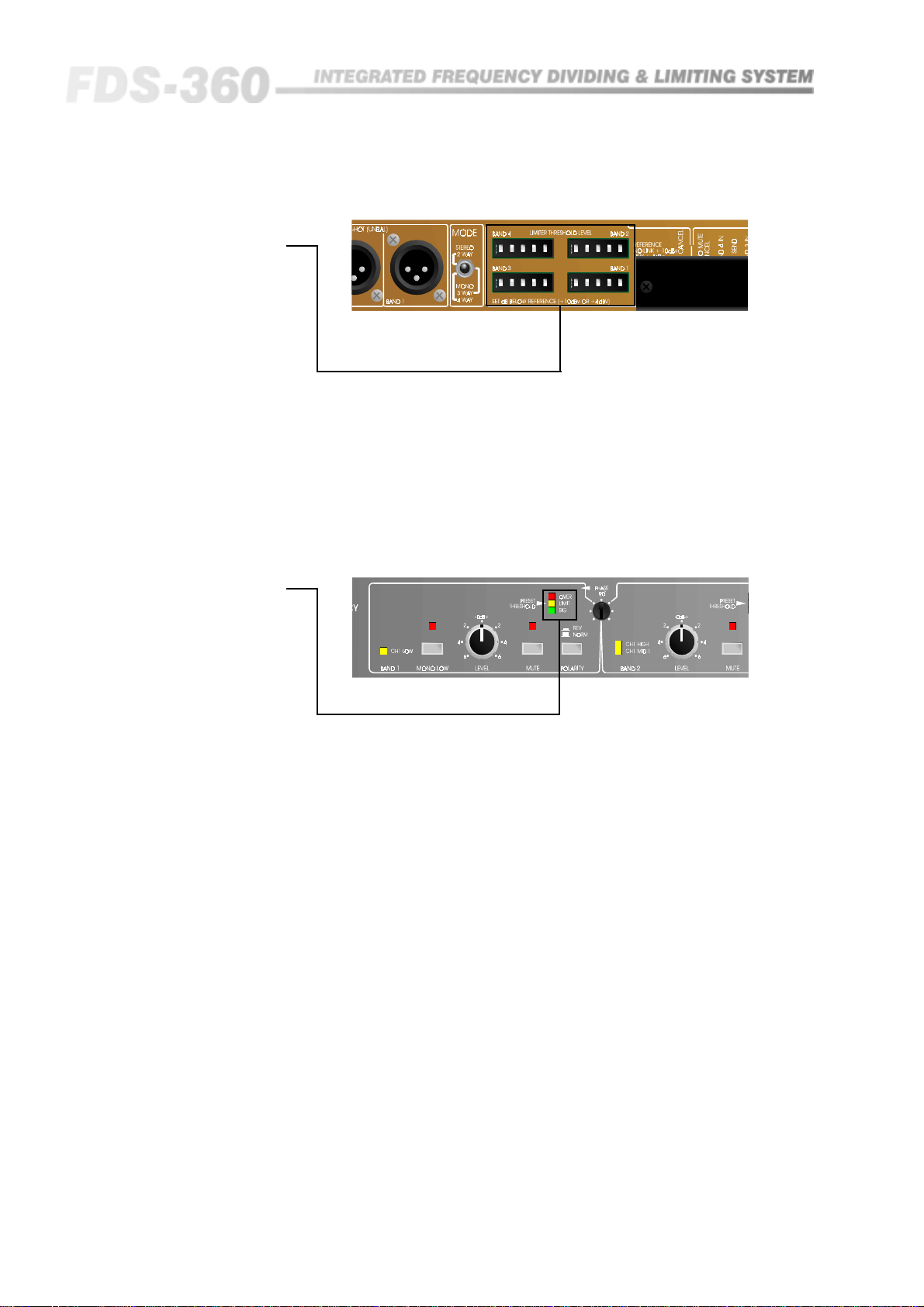
Controls
11.7 Limiter
Threshold Switch
11.8 Signal LEDs
ON
.51248dB
WATS560B
OFF
ON
.51248dB
OFF WATS560B
4H
4H
ON
.51248dB
WATS560B
OFF
4H
ON
.51248dB
OFF WATS560B
4H
These four switch blocks on the rear panel allow the individual band limiter
thresholds to be set. With all switches in the 'out' position, the threshold will
be either +10dBv or +4dBv depending on the barrier strip link.
Binary addition of the switches will then subtract from this reference to give a
specific threshold adjustable in 0.5dB steps. (The centre switch position should
not be used and is provided for manufacturing reasons only). Refer to section
13.1 & 15 for further information.
Each band has associated with it three LEDs which monitor the signal level.
The lower green LED gives an indication that signal is present at a level -15dB
below the limiter threshold setting. The middle orange LED indicates that the
signal has reached the limiter threshold setting, and the upper red LED
indicates 6dB of limiting.
18
Page 19
12.0 Frequency Cards
The frequency programming cards for the FDS-360 are located underneath the
small panel on the top cover of the unit. Access to them is obtained by
loosening the captive screw and then removing the cover. Each frequency
card contains the components required for one low pass filter, one high pass
filter, the limiter dynamics setting and phase control setting. The relevant
frequency, slope and response type is recorded on a label attached to the
respective card.
When fitting the frequency cards take care that they are correctly orientated
and positioned in their edge connectors, and that the foam underneath the
metal cover is locating properly on the edge of the cards to provide correct
support.
Frequency Cards
Card Location for
Four Way System
Card Location for
Three Way System
Card Location for
Stereo Two Way
System
The card located in position FC1 is for the first break point, that in position
FC2 is for the second break point, and that in position FC3 is for the third
break point.
The card located in position FC1 is for the first break point, and that in
position FC2 is for the second break point. The card in position FC3 will not
be used, so its value is not important. However, a card MUST be fitted to
prevent damage to the unit.
The card located in position FC1 is for channel 1, and that in position FC3 is
for channel 2. The card in position FC2 is not used so its value is not
important. A card MUST be fitted in order to prevent damage to the unit.
Refer to section 11 for information on component values for various
frequencies. All standard cards supplied are of the Linkwitz-Riley response
type. Please refer to your dealer who can supply you with cards for other filter
types, as well as frequencies not shown in the tables.
FC1 FC2 FC3
MONO 4-WAY
FC1
STEREO 2-WAYCHANNELONE
FC1 FC2
MONO 3 -WAY
FC3
STEREO 2-WAY CHANNEL TWO
19
Page 20

Rear Barrier Strip
13.0 Rear Barrier Strip
The barrier strip located on the rear of the FDS-360 provides for a number of
facilities specific to the BSS FDS-360, to give the operator greater flexibility.
13.1 Limiter Cancel
13.2 Auto Mute
Cancel
13.3 Limiter
Threshold
Reference
By adding a wire link between the two marked terminals all four limiters can
be cancelled and taken out of circuit. Simultaneously the four red LEDs
marked 'over' on the front panel will illuminate, regardless of the level of the
input signal, to give a warning to the operator that the limiters have been
cancelled.
As mentioned in section 11.1, 'Mode Switch', when the unit is switched on all
four mute circuits will operate to protect the following equipment from
potentially dangerous DC thumps. To commence using the FDS-360 the mutes
will then have to be operated via the respective mute switches. In certain
fixed installations where access to the FDS-360 is not possible by the operator,
it will be necessary to activate the auto-mute cancel facility by adding a wire
link between the two marked terminals. Once activated, the FDS-360 will
still power-up in the mute mode, thus maintaining protection, but after
approximately 20 seconds will automatically un-mute itself to allow full
operation to commence.
As mentioned in section 11.7, 'Limiter Threshold Switch', the limiter threshold
reference is +10dBv. Should a threshold below -5dBv be required, adding a
wire link between the two marked terminals will reduce the reference to
+4dBv, thus allowing a lower threshold point of -11dBv. This operates on all
four limiters together. However, the adjustable range of 15.5dB down from the
reference level allows sufficient adjustment for each individual limiter for
correct speaker protection. Refer to section 15 for further information.
13.4 Band Insertion
Points
20
The barrier strip provides 'send' and 'return' points for each of the four bands
individually. This allows the operator to connect external equipment such as
equalisers and digital time delays into the particular frequency band required.
The send or input to the external equipment or return to the FDS-360 is taken
to the appropriate BAND IN terminal. The factory provided wire link should
obviously be removed. Both the inputs and outputs from the barrier strip are
unbalanced and work at line level with a headroom of +20dBv.
Page 21

14.0 Modes of Operation
The FDS-360 can be configured as either a stereo 2-way, or mono three/fourway electronic crossover. Further possibilities within this framework can be
utilised to allow more flexibility.
Modes of Operation
14.1 Mono Three
Way with Extra Full
Range Buffered
Output
14.2 Operating a
Sub-Woofer system
from an Effects
Send
For applications where only a three way system is used, the fourth way or
band will not be directly used. This can be configured to operate as a full
range (or some form of high pass function) output, with level control, LED
indicators and limiter. This buffered output can be used to drive an auxiliary
sound source such as back stage area, bar area or other full range system. To
utilise this function, a special frequency card is required in position FC3
which bypasses the normal high pass filter sections. Refer to section 18 for
more information on this bypass card.
When operating in the mono three/four-way mode, the input connector and
circuitry for channel two is not utilised. Where a speaker system is configured
as a three way with sub-woofer, using band one is derived from the CHN 2
input section, allowing the operator to drive the sub-woofers from an
independent signal send (possibly an effects send) rather than from the main
stereo left/right sends. To implement this mode of operation the factory fitted
wire link on the barrier strip between CHN 1 SEND and BAND 1 IN should be
removed, and replaced by linking CHN 2 SEND and BAND 1 IN. The same
wire link can be used, and inspection will show that the link is just rotated
around the BAND 1 IN position.
As standard, the FDS-360 has a subsonic filter set for 30Hz, and is some
applications when driving sub-woofer speakers it can be advantageous to
change this down to 15Hz to allow more low frequency energy to pass. This
can be implemented internally, refer to section 17 for further information.
14.3 Mono Low
between separate
units
It will be apparent that this feature of using the CHN 2 input as auxiliary input
is not specific to BAND 1, and can be easily connected to any of the bands IN
terminals. For example, when using the option as in section 12.0 previously,
the band four section can be driven from this auxiliary input to provide
complete and independent control regardless of the main left and right stereo
feeds.
As mentioned in section 11.5, 'Mono Low Switch', when operating in the
stereo 2-way mode, the two LOW output sections can be summed together to
provide a mono signal feed for the low frequency speakers. This facility can
also be used when using two FDS-360 units in a stereo three or four way
speaker system. A flexible wire lead should be connected to join together the
MONO LOW TIE terminals of the barrier strip of each FDS-360. The two
mono low switches on the front panels must also be operated. This allows the
two units to be permanently tied whilst allowing the mono option to be
selected by the front panel switches as required.
21
Page 22

Limiter Adjustment
15.0 Limiter Adjustment
The FDS-360 is provided with separate limiters, each of which are carefully
designed to provide the maximum possible protection to the speaker system
by dynamically controlling the maximum power made available to the power
amplifier, and hence the loudspeakers. The frequency card has components
that optimise its response to suit the frequencies that are being controlled.
The limiter threshold adjustment switches are located on the rear of the FDS-
360 and comprise four identical switch blocks each with five switches
calibrated as : 0.5dB, 1dB, 2dB, 4dB and 8dB. These switches act as
attenuators and are active (ON) when in the fully UP position. This
attenuation is reference to +10dBv or +4dBv depending on the linking of the
rear mounter barrier strip. When shipped from the factory the linking will be
for a threshold of +10dBv reference. The setting of individual threshold levels
is then achieved by selecting the appropriate switches in a binary addition
manner to give the correct number of dBs of attenuation down from the fixed
reference level. Figure 15.1 shows this operation.
The limiters on the FDS-360 can be used in two manners:
Adjustment for A
Adjustment for B
• To control the average power below the maximum that the power
amplifiers are capable of providing. This will protect speaker units that have a
lower power rating than that of the amplifier.
• To allow the maximum power amplifier output to be applied to the speaker
units whilst controlling the transient peaks. This avoids heavy amplifier
distortion, and 'square waves' being applied causing heavy audible distortion
and eventual speaker failure.
Set all limiter adjustment switches to their OUT position. Operate the sound
system up to the acoustic level that is considered safe, or is required, and then
add in the limiter threshold switches to the required amount until the limiter
starts to take control. This can be observed by monitoring the middle LED on
the signal level meter. Further increase of input signal level will then not
cause any further increase in output level.
Obtain the input sensitivity for the power amplifier by referring to its
specification and then set the limiter threshold switches to give a threshold of
1dB BELOW this level. Since all power amplifiers' dynamic power output are
a function of their specific design and the mains voltage present at the time,
some adjustment from this setting might be required. The ability to adjust
threshold in 0.5dB increments gives ample scope for accurate setting. The
table in Figure 15.1 lists some of the common signal levels in Volts and dBv
as an example of typical switch settings.
22
Page 23
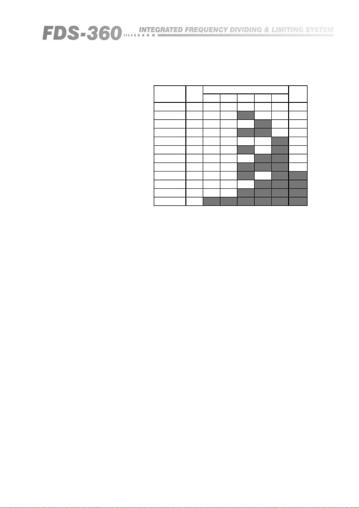
Fig 15.1 Limiter
Threshold Settings
RMS Volts
2.47
1.95
1.56
1.24
0.98
0.78
0.62
0.49
0.39
0.31
0.25
0.21
The 1 and 0.5dB switch positions should be used to set for intermediate
settings. The grey box indicates that the switch is ON. A blank box indicates
that the switch is OFF. The '+4dBv Link' refers to the strap on the barrier strip.
dBv
+10
+8
+6
+4
+2
0
-2
-4
-6
-8
-10
-11.5
Switch Settings 4dBv
0.51248
Link
23
Page 24

Phase Adjustment
16.0 Phase Adjustment
One of the characteristics of the Linkwitz-Riley filter response is that at the
'corner' frequency between two adjacent bands the phase of the signal from
each band is the same. i.e. the two output signals are in phase. (Some small
departure from this occurs in band-pass outputs due to residual effects from the
opposite 'corner' frequencies).
In order to assist in obtaining accurate acoustical summation of the signals
from adjacent speaker units in a loudspeaker system, it is desirable to be able
to adjust the phase of the signal from one frequency band to that from the next
frequency band to properly allow for any phase errors that occur in the actual
loudspeakers and cabinets themselves. The three 'phase' controls on the FDS-
360 are provided for this purpose.
It will be noticed that a small arrow associated with the graphics around this
phase control indicates which frequency band is being moved 'with' reference
to the other adjacent band, and that band four having no such control operates
as the starting reference.
In operation, phase alignment should commence at the highest frequency
band being used, and all other bands then adjusted in sequence down from
this band. Owing to residual effects as mentioned above, if after initial
adjustment some further re-adjustment is done on any band, then the lower
bands will need re-adjusting to compensate.
The polarity switch associated with each band can also be used to provide
further control range. If having rotated the phase control fully clockwise,
phase alignment is not achieved, then the polarity switch can be operated.
Returning the phase control to zero will then give the previous setting,
allowing a further 180 degrees of control. It should be remembered that this
phase adjustment is designed to assist in obtaining correct phase alignment
around the crossover frequencies of the speaker system, and is not the
equivalent of inserting digital delays into the frequency band. Should this be
required, then you should refer to section 13.0 of the manual.
To assist in setting up the phase controls, a number of methods can be tried:
• Using pink noise and a spectrum analyser will provide a pictorial view of
the acoustical energy around the crossover regions, and operation of the phase
controls should be made to give the flattest response.
• Careful listening test to the speaker system whilst operating the phase
controls will provide another method of alignment.
• Applying a sinewave signal at a frequency equal to each crossover point in
turn, through the speaker system will allow operation of the phase control to
achieve a minimum speaker level. i.e. a cancellation. Pressing the polarity
switch will then invert one of the outputs to achieve a true summation.
24
Page 25

System Diagram/Description
17.0 System Diagrams and Descriptions
17.1 Full unit
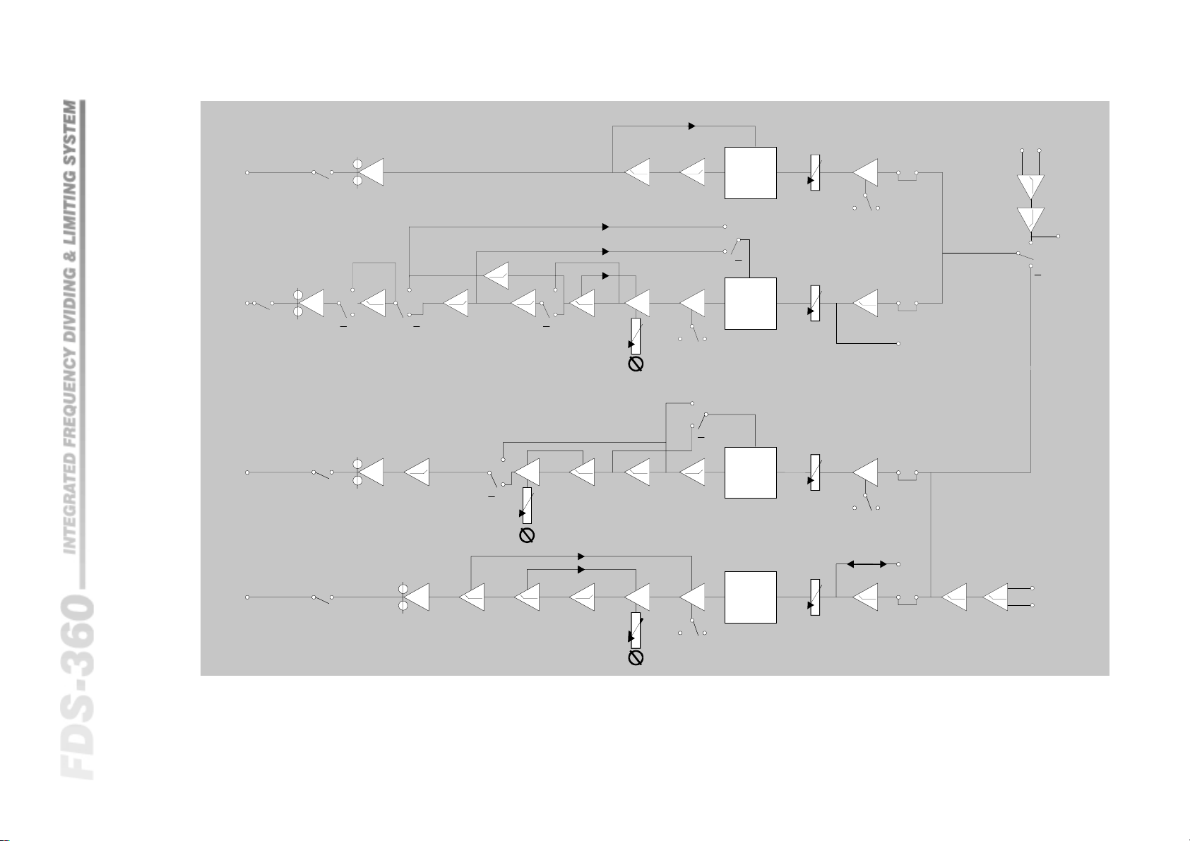
The input section of the FDS-360 contains the input signal de-balancing,
subsonic and ultrasonic filtering. From here the signal is fed into four parallel
paths for filtering and limiting. These four paths are essentially similar, apart
from the number and types of filters required. The input for channel 2 is fed
via the mode switch.
The gain reduction circuitry for the limiters is located after the level controls
and before the main crossover filters, and is of the feedback type. The main
crossover filters consists of two series second order filter blocks configured to
achieve the Linkwitz-Riley response. By utilising separate order filters in this
manner, it is possible to have 12, 18 or 24dB/OCT responses with the low and
high pass filters having either the same or differing cutoff frequencies. This
flexibility is achieved by suitable programming of the plug-in frequency cards.
The DC control voltage for the limiter circuits is derived from a point between
the two series filter sections which avoids the frequency-shift effect when
limiting occurs. The dynamic time constants are set by capacitor C10 on the
frequency card. The phase control linearity is set by capacitor C9 on the
frequency card. The final output stages driving the MUTE relays utilise
discrete output transistors to ensure adequate current drive into long lengths of
signal cable. The MUTE relays are controlled by the front panel mute switch,
the power-up auto mute routine, the auto mute cancel facility, and the
circuitry which monitors the power supply circuits. If for any reason the
internal power supplies fail, all mute relays operate to protect the output from
any DC output levels. See next page for a full system block diagram.
17.2 15Hz Subsonic
Filter Change
As mentioned in section 14.0, the cutoff frequency of the subsonic input filter
is set as standard at 30Hz. For sub-woofer speaker systems, it may be
desirable to change this down to 15Hz. Should this be required, the following
table details the extra capacitors that should be fitted into the appropriately
marked space on the main circuit board of the unit.
Channel 1: C2, C4, C24A, C23A, C27A as 220nF 5% C28A as 470nF 5%
Channel 2: C14, C15, C34A, C35A, C36A as 220nF 5% C73A as 470nF 5%
25
Page 26
1OUTPUT
CHANNEL
F3F3MUTE
BAND4OUTPUT
30
3w
3w
BAND3OUTPUT
2w
2w
F3MUTEF3F2F2
3w
3w
POL
2w
2w
LIM
INSERTLEVEL
3w
3w
LIM
POL
INSERTLEVEL
MONOTIE
30
27k
2w
OUTPUT
2
CHANNEL
2w
BAND2OUTPUT
BAND1OUTPUT
System Block Diagram
F1
2w
F22wMUTE F2F1
30F1F1MUTE
LIM
INSERTLEVEL
POL
MONOTIE
30
LIM
POL
27k
INSERTLEVEL
1OUTPUT
CHANNEL
26
Page 27
Filters and Frequency Tables
18.0 Filters and Frequency Tables
18.1 Standard
Filters
18.2 Full Range
Frequency Card
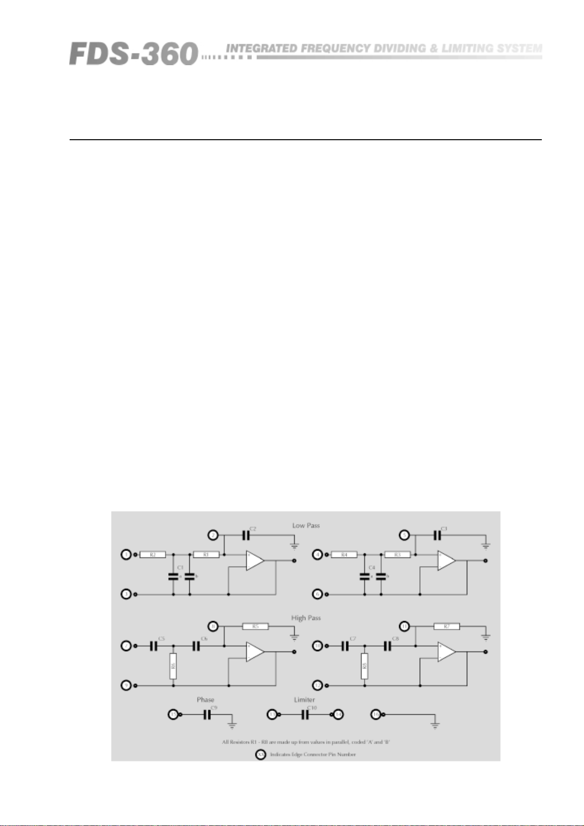
Fig 18.1 Frequency and
Component Function
The standard filter provided for the FDS-360 is of the Linkwitz-Riley response
based on two second order Butterworth circuits in series. The response is a
24dB/OCT slope with a 'corner' frequency where the output of the filter if 6dB
down from its pass band level. The use of these filter realisations has been
well documented and provides the best possible phase and amplitude response
for driving large speaker systems.
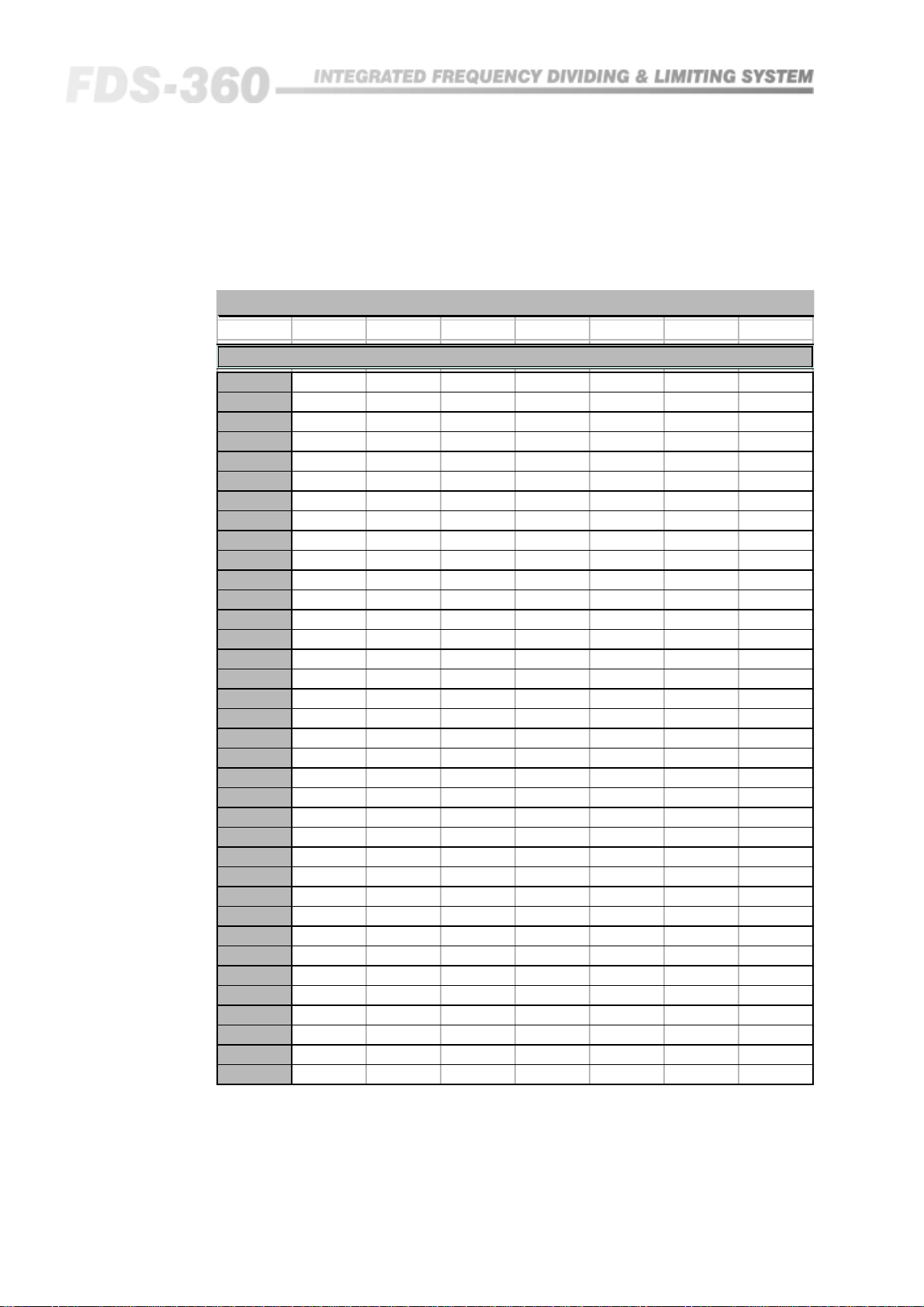
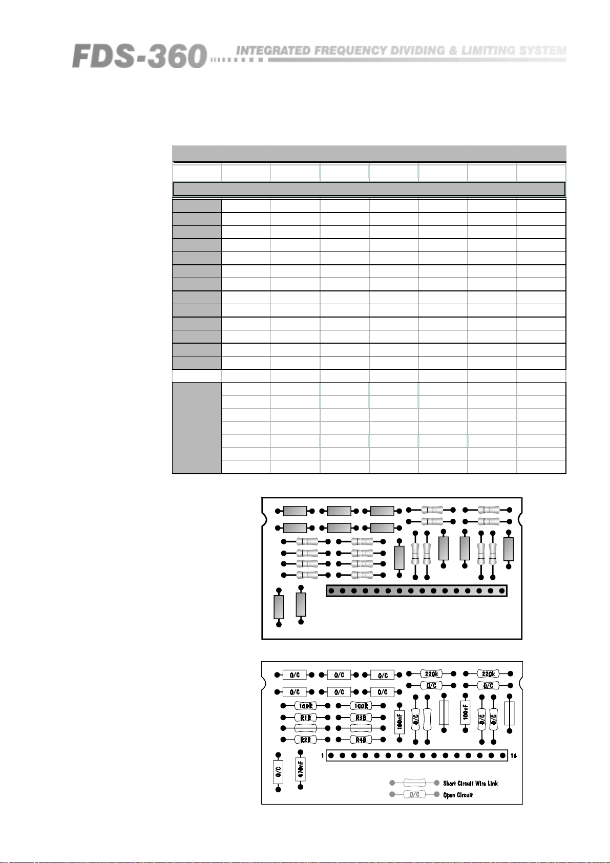
Table 17.1 lists the component values for various frequencies and should be
used in conjunction with the drawing for the FDS-360F frequency card (See
Figure 18.3). Blank cards, or ready made cards can be provided by any BSS
dealer.
All resistors should be ¼W metal film 2% tolerance or better. Capacitors
should be 5% tolerance or better. Figure 18.1 shows how these components
relate to the separate filter blocks to assist in making mixed frequency cards
that might be needed for speaker systems that require gaps or overlaps in the
amplitude response of the filters. Other filter responses can also be realised
using these frequency cards, and your dealer will be able to supply these to
order.
Should the fourth band output be required to work as a full range buffered
output (See section 14.1), a full range frequency card is required to be inserted
into FC3 position. This card removes all filtering associated with the third
frequency point. The limiter setting capacitor C10 should be chosen to suit the
lowest frequency in the band, which would normally be 30Hz. Figure 18.4
shows the frequency card modified for this result.
27
Page 28
Filters and Frequency Tables
Fig 18.2 Component
Values for Frequency
Cards type FDS-360/1
FDS-360 FREQUENCY CARD COMPONENT SELECTION - 24dB/Octave
Freq.R1R1R5R5C1C10C9
50
60
63
70
80
100
110
125
150
160
180
200
220
250
280
300
350
400
500
600
800
1k0
1k2
1k3
1k5
1k6
2k0
2k5
3k0
3k5
3k7
4k0
4k5
5k0
5k5
6k0
43k 47k 82k 100k 100nF 330nF 150nF
36k 39k 75k 75k 100nF 330nF 150nF
33k 39k 47k 150k 100nF 330nF 150nF
16k - 39k 180k 100nF 330nF 150nF
15k 220k 39k 100k 100nF 220nF 100nF
18k 30k 24k 330k 100nF 220nF 100nF
12k 68k 39k 43k 100nF 150nF 68nF
18k 18k 18k - 100nF 150nF 68nF
7k5 - 15k - 100nF 150nF 68nF
8k2 47k 15k 220k 100nF 150nF 68nF
6k2 - 13k 330k 100nF 150nF 68n F
18k 330k 39k 270k 33nF 150nF 68nF
18k 100k 100k 47k 33nF 100nF 47nF
15k 150k 27k - 33nF 100nF 47nF
13k 180k 43k 56k 33nF 100nF 47nF
15k 47k 27k 150k 33nF 100nF 47nF
15k 27k 39k 39k 33nF 100nF 47nF
10k 56k 18k 330k 33nF 100nF 47nF
6k8 - 15k 150k 33nF 47nF 22nF
6k2 68k 15k 47k 33nF 47nF 22nF
39k 22k 39k 100k 10nF 47nF 22nF
12k 180k 47k 43k 10nF 33nF 15nF
10k 150k 27k 62k 10nF 33nF 15nF
10k 68k 18k 470k 10nF 33nF 15nF
7k5 - 15k - 10nF 22nF 10nF
8k2 47k 22k 39k 10nF 22nF 10nF
8k2 18k 12k 180k 10nF 22nF 10nF
18k 56k 27k - 3n3F 15nF 4n7F
15k 47k 24k 470k 3n3F 15nF 4n7F
10k 330k 24k 100k 3n3F 15nF 4n7F
39k 12k 27k 56k 3n3F 15nF 4n7F
10k 56k 39k 30k 3n3F 15nF 4n7F
8k2 100k 18k 100k 3n3F 10nF 3n3F
6k8 - 18k 56k 3n3F 10nF 3n3F
6k2 - 13k 270k 3n3F 10nF 3n3F
6k2 68k 15k 47k 3n3F 10nF 3n3F
28
Page 29
FDS-360 FREQUENCY CARD COMPONENT SELECTION - 24dB/Octave
See Notes at bottom f or f ul l c om ponent ID.
Freq. R1A R1B R5A R5B C1A C10 C9
6k3
6k5
7k0
7k5
8k0
8k5
9k0
9k5
10k0
12k0
15k0
18k0
20k0
R1A
R1B
R5A
R5B
C1A
C9
C10
27k 6k8 27k 18k 3n3F 10nF 3n3F
22k 6k8 12k 82k 3n3F 10nF 3n3F
39k 5k6 13k 39k 3n3F 10nF 3n3F
10k 8k2 18k 18k 3n3F 6n8F 2n2F
10k 7k5 10k 62k 3n3F 6n8F 2n2F
4k7 27k 8k2 330k 3n3F 6n8F 2n2F
3k9 120k 8k2 100k 3n3F 6n8F 2n2F
15k 56k 82k 33k 1n0F 6n8F 2n2F
15k 47k 43k 47k 1n0F 6n8F 2n2F
12k 43k 27k 62k 1n0F 6n8F 2n2F
7k5 - 15k - 1n0F 6n8F 2n2F
6k2 - 15k 82k 1n0F 6n8F 1n0F
5k6 - 13k 82k 1n0F 6n8F 1n0F
=
R1A , R2A, R3 A , R4A, R6 A, R8 A
R1B , R2B, R3 B , R4B, R6 B, R8 B
=
=R5A, R7A
=R5B, R7B
=
C1A, C1B, C2, C3, C4A, C4B, C5, C6, C7, C8
=C9
=C10
Fig 18.3 FDS-360F
Component Overlay
Fig 18.4 FDS-360F Full
Range Overlay
C1A
C1B
R1A
R1B
R2A R4A
R2B
C10
C9
C2
116
C4A
C4BC3
R3A
R3B
R4B
R5A
C6
R6B
R6A
C5
R7A
R7BR5B
C7
C8
R8B
R8A
29
Page 30

Supported Options
19.0 BSS Supported Options
19.1 Output
Balancing
19.2 Security Cover
The FDS-360 has unbalanced output as standard. Should output balancing be
required, then the BSS AR204 line balancing unit should be used. This unit
provides four input/output circuits, each isolated by a transformer. It utilises a
custom designed high quality toroidal transformer carefully developed to
accommodate high line level signals down to 15Hz. The maximum load
should not exceed 600 ohms. The size and weight of the transformers does not
permit them to be included as part of the case structure of the FDS-360, so
provision has been made for the AR204 to be either rack mounted or a 1U
front panel (which has the capacity to mount 2 x AR204), or to be individually
mounted inside the racking system of the installation. Connections between
this and the FDS-360 are standard 3 pin XLR leads.
In installations where fully tamper proof security is required, the FDS-360-SC
security cover system can be fitted. This recesses and covers the front panel of
the FDS-360 behind a blank steel panel, such that no access is gained to any
of the front panel controls. Fitting instructions for this are provided with each
kit.
30
Page 31

Equalisation Options
20.0 FDS-360 Equalisation Options
20.1 Introduction
20.2 FDS-360D
Installation
In certain areas of application, it is necessary to have within a loudspeaker
system some form of fixed equalisation to enable a particular type of sound to
be reproduced. This can be to overcome problems of room resonances or
individual loudspeaker frequency responses. This fixed equalisation is
generally provided by an external graphic equaliser or parametric equaliser
connected into the main program signal chain prior to the crossover input.
Although this system works well, it is expensive to tie up a dedicated
equaliser which is set once during installation of the sound system, and then
locked away so that no other operator can gain access to it. In some instances
it can also be difficult to obtain the correct degree of equalisation for a
loudspeaker drive unit when the adjustment required is close to its crossover
frequency, as the effects will also be mirrored by the adjacent loudspeaker
drive unit.
Carefully inspect your equalisation board for any transient damage and check
that you have the two support pillars and mounting screws provided. Follow
the procedure shown by steps 1-5 below:
1 Remove the frequency card access plate, and top and bottom cover plates
from the FDS-360.
2 Fit the two support pillars onto the main circuit board using the screws and
washers provided. Replace the bottom cover.
3 Carefully cut and remove the four resistors located in position Link 1-4 on
the main circuit board and adjacent to the 14-way connector socket, SKT 1.
(Do not unsolder these components as their leads are used as through
connections).
20.3 Circuit
Description
4 Mount the equalisation board onto the support pillars and secure the screws
and washers provided. Carefully fold the ribbon connection cable and plug
into SKT 1.
5 Refit the top cover and frequency card access cover plate.
Installation of the equalisation card is now complete.
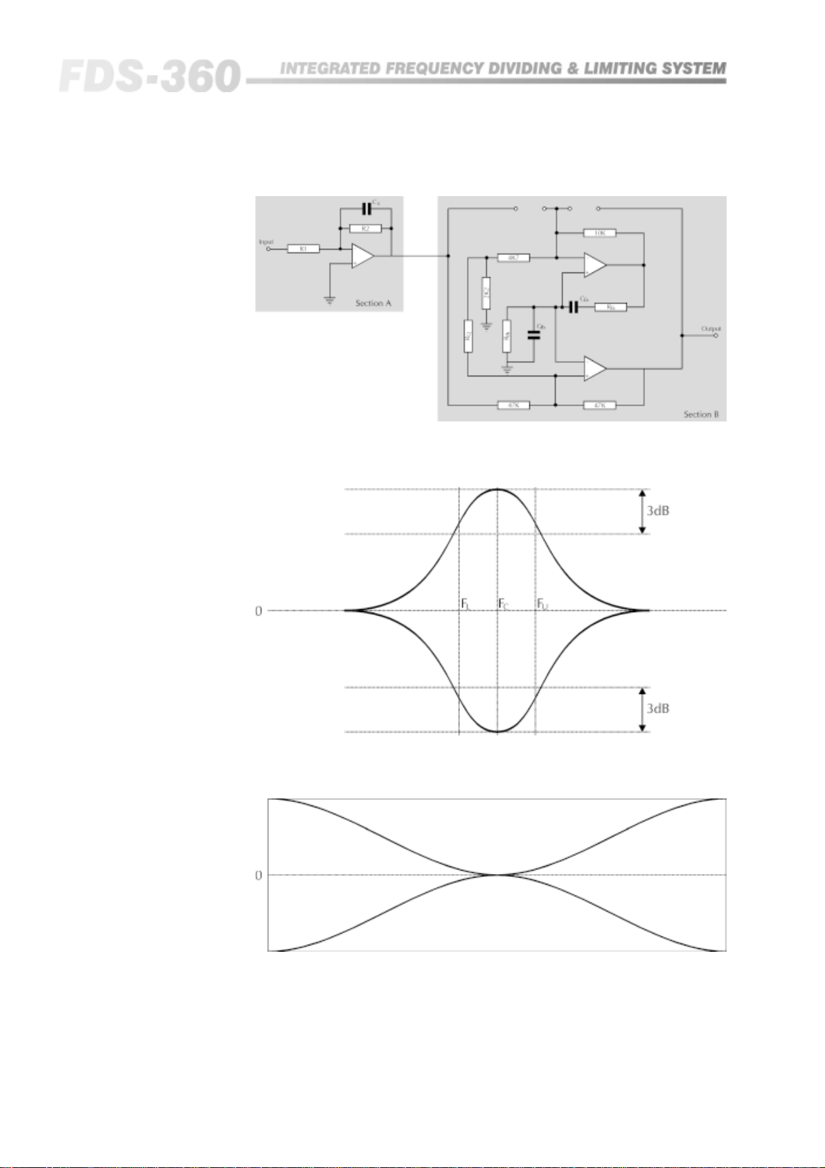
The FDS-360D contains four identical blocks of circuitry coded as FLTR 1, 2 ,
3 and 4. One such block is shown below (See figure 20.1).
This filter block contains section A, a 1st order low pass filter, and section B, a
fully parametric equaliser. These two sections can be used to configure any
form of cut or boost Bell response or LF/HF shelving response, as indicated in
Figure 20.2 overleaf.
As it is unlikely that all four bands of the system will require equalisation,
spare sections can be used in series to increase the complexity for a particular
band. Reference to the attached full circuit diagram and the component
overlay of Figure 20.3 will show the various interconnection methods
designed to interface these filter blocks into the correct crossover frequency
band.
31
Page 32
Equalisation Options
Fig 20.1 Schematic for
one filter block
Fig 20.2 Bell Response
curve for filter block
Fig 20.3 HF/LF Response
curve for filter block
32
Page 33

20.4 Filter Design
Reference should be made to Figure 20.1.
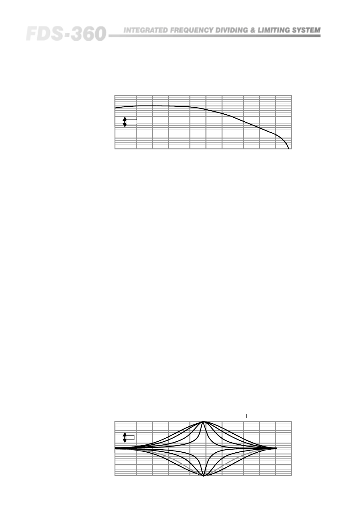
Section A: First Order Low Pass Filter.
This can be used in conjunction with that of section B, and an example plot is
shown in Figure 20.4.
The equation for the -3dB frequency point of this circuit is:
F = 1/(6.28 x R2 x Cx), where R is in ohms,
C is in Farads,
F is in Hz.
Note should be taken that R2 is factory fitter as 10k ohms. Inspection of the
circuit will show that it is also possible to change the gain of the filter block
at this point. The actual gain in dB is:
G(dB) = 20 x log(R2/R1)
It should also be noted that both R2 and R1 are factory fitted as 10k ohms, and
should the value of R2 be changed, this must be accounted for in the
calculation of Cx.
Design limits for both R1 and R2 are in the range of 2k to 100k ohms. There is
no restriction on the value of Cx, apart from physical space on the circuit
board.
33
Page 34
q
q
Equalisation Options
Fig 20.4 First Order
Sample Response
First Order Response Cf = 15nF, Fc (-3dB) = 1kHz
10dB
20 50 100 200 500 1k 2k 5k 10k 20k 40k
uency(Hz)
Fre
Section B: Parametric Equaliser Filter.
This is a fully adjustable bell shape equaliser for which control is given over:
• Centre frequency
• Q, or the sharpness of the Bell shape
• The amount in dB of the boost or cut.
A sample response of this equaliser is shown in Figure 20.5:
1. Centre Frequency:
This is set by four components; Rfa, Rfb, Cfa and Cfb, and is given by the
following equation:
Fc = 1/[6.28 (R*fa/b . C*fa/b)], where R is in ohms,
C is in Farads,
F is in Hz.
Fig 20.5 Parametric
Equaliser Sample
Response
For symmetrical and normal responses note that Rfa = Rfb and Cfa = Cfb, and
the equation reduces to:
Fc = 1/(6.28 x Rf x Cf)
Such that for Rfa = Rfb = 10k and Cfa = Cfb = 16nF than Fc = 1kHz.
Design limits for Rf should be within the range 2k to 100k ohms. There are no
limits for Cf apart from physical space on the circuit board.
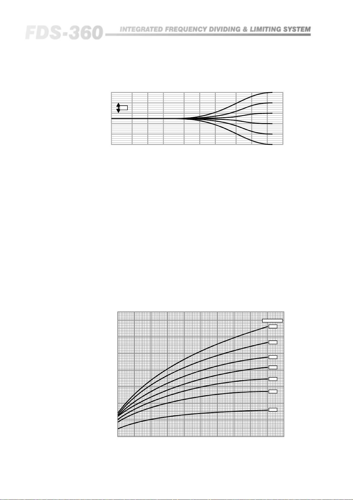
2. Q and dB Boost/Cut:
Both of the parameters Q and dB are set by a single resistor, Rq and RdB
respectively. To some extent they are interactive and it is therefore easiest to
obtain their values from a set of graphs (See figure 20.10 and 20.11). These
allow for ranges of Q from 0.2 to 3.0 and for a range of boost/cut of up to
16dB.
For further information on deciding on the values of these filter variables,
refer to section 20.5.
Bell Response RQ values, 0 , 1k , 4k7, = 12.5dB
5dB
ΩΩ
8
34
20 50 100 200 500 1k 2k 5k 10k 20k 40k
Fre
uency(Hz)
Page 35
20.5 Application
q
l
f
f
f
)
Notes
100Hz Notch to reduce mains related interference
The design specification for this would be:
Fc = 100Hz
Q = Maximum possible
dB cut= Maximum possible
Using the Fc equation given earlier, and selecting Cf = 220nF gives a value
for Rf = 7.23k ohms.
Using the graph for Rq will indicate that for a maximum value for Q, the
value of Rq should be also be a maximum. In this circuit we can allow Rq to
be infinite, so the design value for Rq would be open circuit, and no resistor
would be fitted in this position.
Using the graph for RdB will indicate that a minimum value for RdB is
required for a maximum value for boost/cut. In this circuit we can set a
minimum value for this of 10k ohms. (Ensure this resistor is fitted in the 'cut'
of 'C' position on the circuit board).
Notch depths of up to 50dB can be achieved, however this depends on the
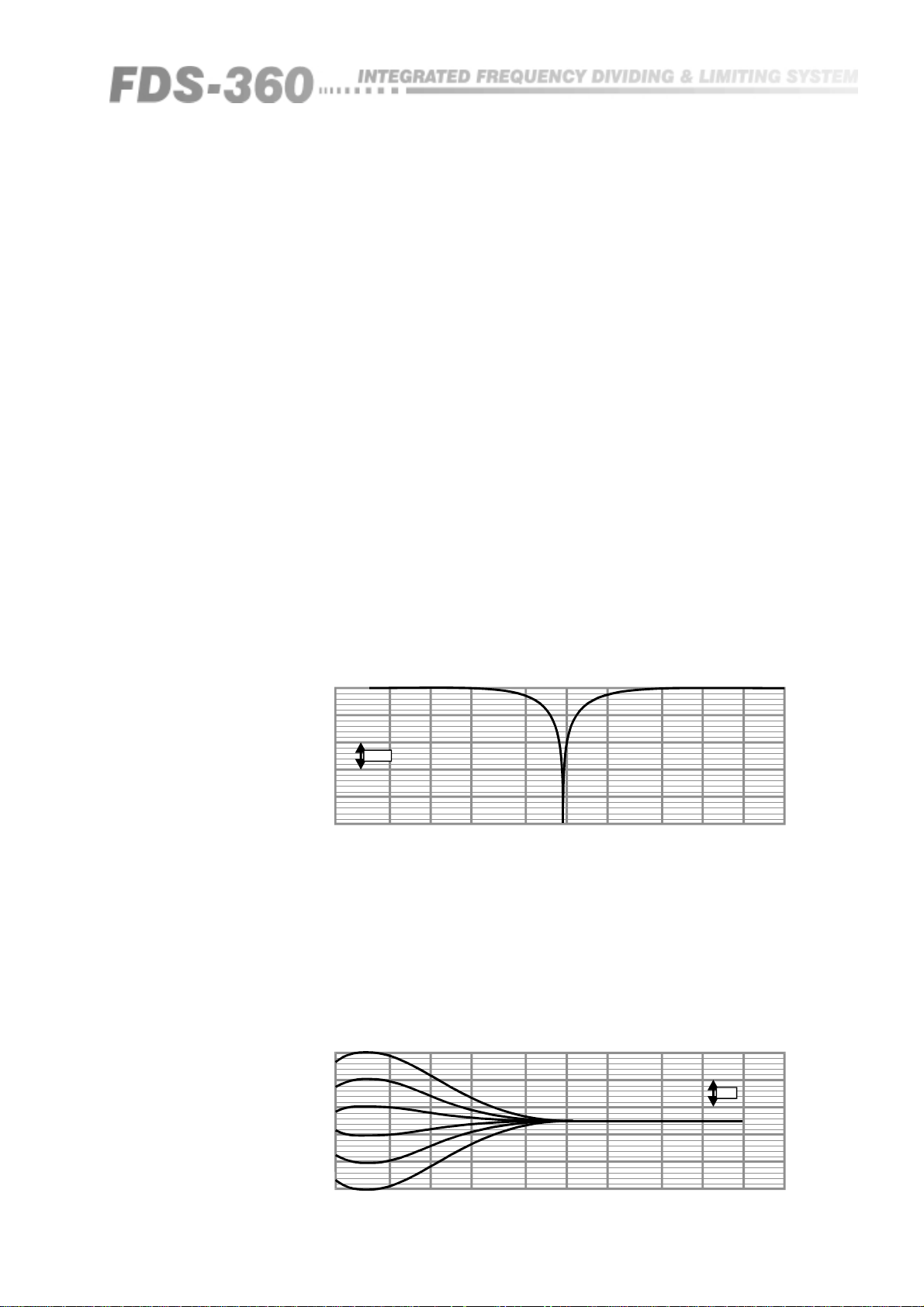
close matching of the frequency determining components. An example of this
notch circuit is shown below in Figure 20.6.
Fig 20.6 Sample Notch
Response Curve
Fig 20.7 Sample LF
Shelving Response
Curves
NotchResponse RQ = , Rcut = 10k, Fc = 960Hz
10dB
20 50 100 200 500 1k 2k 5k 10k 20k 40k
uency(Hz)
Fre
8
Shelving Filter:
Utilising the parametric section and selecting a very low Q value will
achieve a standard shelving type response filter of their boost or cut. Selecting
a low Fc (such as 30Hz) will give a bass shelving response, and selecting a
high Fc (such as 20kHz) will give a treble shelving response. An example of
these shelving curves is given below in Figure 20.7.
LF She
RQ = 0, Fc = 35Hz(Responsedi
erencedue to subsonicfilter.
5dB
20 50 100 200 500 1k 2k 5k 10k 20k 40k
Frequency(Hz)
35
Page 36
q
Equalisation Options
Fig 20.8 Sample HF
Shelving Response
Curves
20.6 Application of
the FDS-360D to a
system
HF Shelf RQ = 0, Fc = 16kHz
5dB
20 50 100 200 500 1k 2k 5k 10k 20k 40k
uency(Hz)
Fre
A target response should be arrived at by either inspection from a set of
frequency response curves, or by adjustment of an external equaliser
connected into the system. For simplicity, only one frequency band of the
crossover has been considered.
Take a plot of the unmodified frequency response of the FDS-360 and on the
same sheet of graph paper plot the target response. A third plot is then drawn,
which is the difference, in dBs, between the two curves and this 'correction'
curve is the desired response of the FDS-360 equalisation section. From this
correction curve, the amount of dB boost or cut and the centre frequency, Fc,
are easily obtained by inspection. The required Q value can either be
obtained by calculation or estimated by comparison with the sample curves
provided with this manual.
The equation of Q of a Bell response curve is:
Fig 20.9 Design Curves
for Rq.
Q = Fc/(Fu - Fl),
where Fu and Fl are the frequencies at which the amplitude response is 3dB
down from the value at Fc.
Q
3.0
2.8
2.6
2.4
2.2
2.0
1.8
1.6
1.4
1.2
1.0
0.8
0.6
0.4
0.2
0
0 1k2k3k4k5k6k7k8k9k10k
QvsRQforVariousDegrees of Boost/Cut FDS-360D
dB Boost/Cut
16dB
14dB
12dB
10dB
8dB
6dB
4dB
RQ (ohms)
36
Page 37
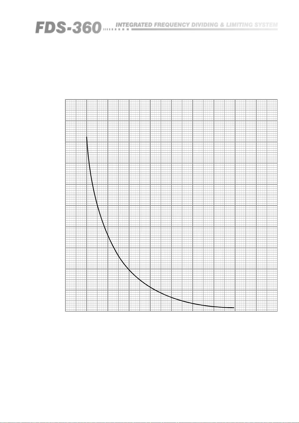
Fig 20.10 Design Curves
for RdB
R Boost/Cut
(k )
RBoost/Cut vsdBBoost/Cut
Ω
400
380
360
340
320
300
280
260
240
220
200
180
160
140
120
100
80
60
40
20
01234567891011121314151617
dB Boost/Cut
37
Page 38
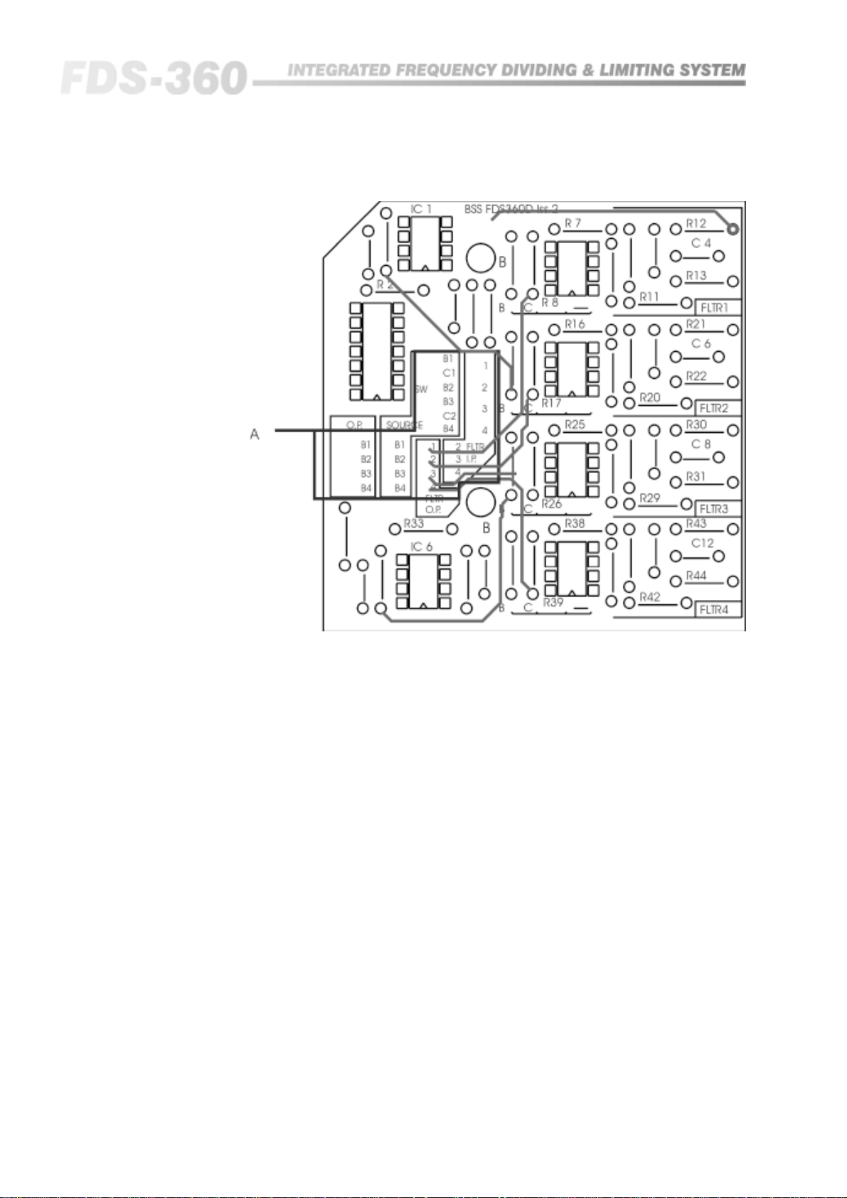
FDS 360 D-Card
Connection of the filter blocks into the FDS360 frequency bands is arranged
by the wire link strapping between the various connection areas:
Filter I.P : Are the inputs to the filter blocks.
Filter O.P : Are the outputs of the filter blocks.
O.P : Are the band insert returns, and are connected to the Filter O.P.
SOURCE : Are the band insert sends, and are connected to the Filter I.P
Note that the main CHN1 and CHN2 input signals are also provided, as is the
switched send.
Reference to the FDS360 block diagram in section 20.3 will help clarify the
exact position of these signal feeds and insertion points.
38
Page 39
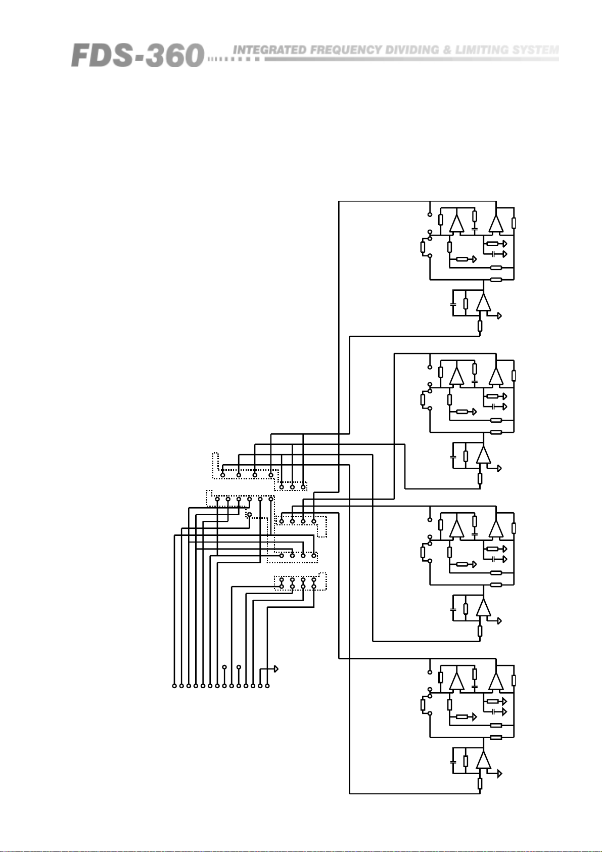
Fig 20.12 FDS360 EQ 'D'
card Schematic
1
FILTERINPUT
B1C1B2
SOURCE
CUT
SOA
R39
CUT
R26
SOA
2
3
4
234
B3SWC2
B4
123
B1B2B3
B1
B2B4B3
4
FILTER
OUTPUT
B4
OUTPUT
CUT
SOA
R17
1
R41
IC7
353
R42
10K
+
2
3
4K7
R40
R43
BOOST
R29
10K
BOOST
R20
10K
BOOST
2K2
10K
R35
C10
SOA
1
R28
IC4
353
+
3
2
R27
4K7
R30
2K2
R34
10K
C9
SOA
1
IC3
353
R19
+
3
2
4K7
R18
R21
2K2
R1
10K
C1
SOA
7
SOA
IC7
353
R37
47K
+
C11
SOA
5
6
R44
SOA
C12
SOA
R38
SOA
R36
47K
1
IC6
353
+
2
3
10K
R33
SOA
IC4
353
R24
47K
+
C7
SOA
5
67
R31
SOA
C8
SOA
R25
SOA
47K
R23
IC6
353
+
576
10K
R32
IC3
353
SOA
IC1
R2
10K
R15
47K
+
SOA
5
67
R22
SOA
C6
SOA
R16
SOA
47K
R14
7
353C5
+
5
6
+15V
-15V
1
PLG1
14WDILHEADER
BAND4SEND
SWITCHEDSEND
7
+15V
BAND2SEND
BAND3SEND
BAND1RTN
BAND1SEND
CHAN.1SEND
CHAN.2SEND
14
-15V
0VEARTH
BAND3RTN
BAND4RTN
BAND2RTN
CUT
R8
SOA
1
353
IC2
R11
10K
+
2
3
R9
4K7
BOOST
R12
2K2R10
R3
10K
C2
SOA
SOA
IC1
R4
10K
C3
SOA
R13
SOA
353
213
IC2
C4
SOA
+
76
353
R6
47K
+
5
R7
SOA
R5
47K
39
Page 40

FDS 360 E-Card
20.7 FDS-360 E
Installation
Fig 20.13 Boost resistor
values
The 360E board filters 3 and 4 are shelf type filters which can be configured as
High or Low pass cut or boost. Filters 1 and 2 remain the same as the
parametric EQ filters on the 360D board (See section 20.4 for further details).
The design idea for filters 3 and 4 is to provide gentle slopes which will
enhance or cut low or high frequencies. To obtain these results only 1 resistor
value is needed, and the frequency is changed using different capacitor
values, typically between 4.7n and 22n.
For high pass cut/boost, X1 + X3 is a resistor and X2 + X4 is a capacitor.
For low-pass cut/boost, X1 + X3 is a capacitor and X2 +X4 is a resistor.
If the 4.7K resistor is changed, there may be some interaction between boost
resistors R23 + R34 to R28 + R39 (See figure 20.13 for boost resistor values). If
this occurs, the values of R23 + R34 to R28 + R39 will have to be changes
accordingly.
On the PCB there are 6 positions for the boost resistors, set to give 1dB to 6dB
of boost. The resistor values which can be used with these are shown below.
R23 + R34 = 82K
R24 + R35 = 39K
R25 + R36 = 24K
R26 + R37 = 18K
R27 + R38 = 13K
R28 + R39 = 10K
BSS currently use a software package called Analyser III to produce the results
for the EQ boards. If you want to check this out, it can be obtained from a
company called Number One Systems, at the following address:
Number One Systems
Somersham Road
St. Ives
Huntingdon
Cambridgeshire
PE17 4WR
England
Tel : +44 480 61778
Fax : +44 480 494 042
40
Page 41
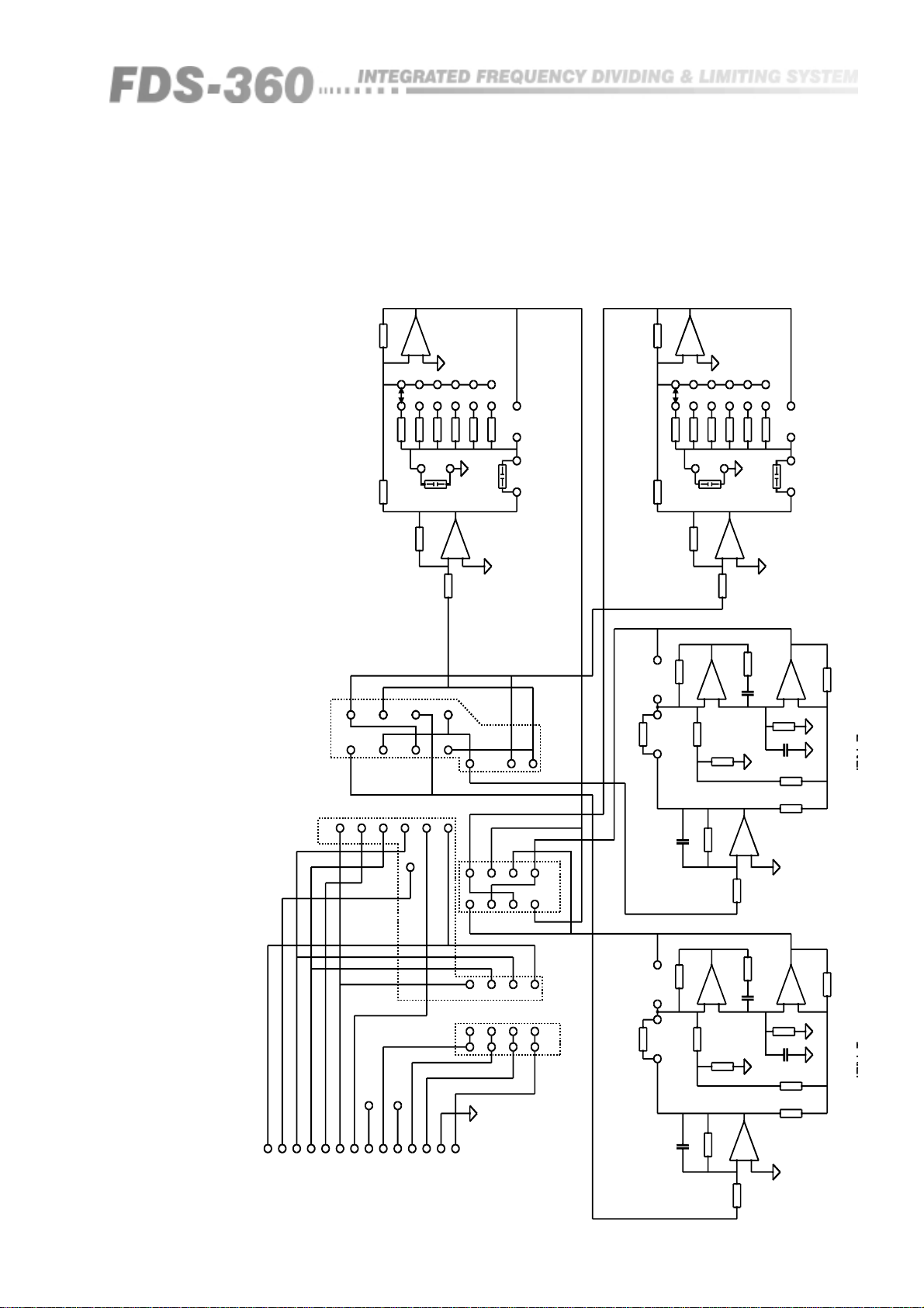
Fig 20.14 FDS-360 EQ 'E'
FLTR2
FLTR1
Card Schematic
1
IC4
10K10K
R32R33
3
4
2
1
FILTERINPUT
353
+
2
3
1
2
3
4
5
dB
R2524K
R2439K
R2382KS1
X1
SOA
R31
10K
6
1
2
4
3
6
R2810K
R2713K
R2618K
SOA
BX2C
FLTR4
BOOSTCUT
7
IC4
353
+
5
10K
R29
R17
4
3
2
SOA
1
IC5
R44R43
10K10K
CUT
R20
353
+
3
2
dB
BOOST
3
2
1
S282KR34
39KR35
24KR36
SOA
X3
10K
R41
6
1
IC3
353
10K
+
2
3
4K7
R18
6
5
4
CUT
18KR37
13KR38
10KR39
SOA
BX4C
FLTR3
BOOST SOA47K
7
IC5
353
+
5
R42
10K
7
SOA
R19
IC3
353
47K
R15
+
C5
SOA
5
6
SOA
R22
2K2
R21
C6
SOA
SOA
R16
7
IC1
353
R1
B1
SEND
+15V
1
14WDILHEADER
PLG1
BAND4SEND
BAND3SEND
SWITCHEDSEND
7
+15V
BAND2SEND
CHAN.1SEND
BAND1RTN
BAND1SEND
CHAN.2SEND
B4
C2
SW
-15V
14
1
3
1
B1
B1
2
4
4
3
2
B2
B3B4B2
OUTPUT
FILTER
B4
B3
RTN
CUT
R8
SOA
-15V
0VEARTH
BAND2RTN
BAND3RTN
BAND4RTN
B3
B2
C1
10K
C1
SOA
IC2
353
10K
R11
R9
4K7
BOOST
R3
10K
C2
SOA
+
6
R2
10K
1
SOA
R10
+
3
2
R13
2K2
R12
IC1
353
+
R4
10K
47K
R14
5
IC2
353
47K
R6
+
C3
SOA
5
67
SOA
C4
SOA
R7R5
312
41
Page 42
Chassis Earth Link
Transient Suppressor Replacement
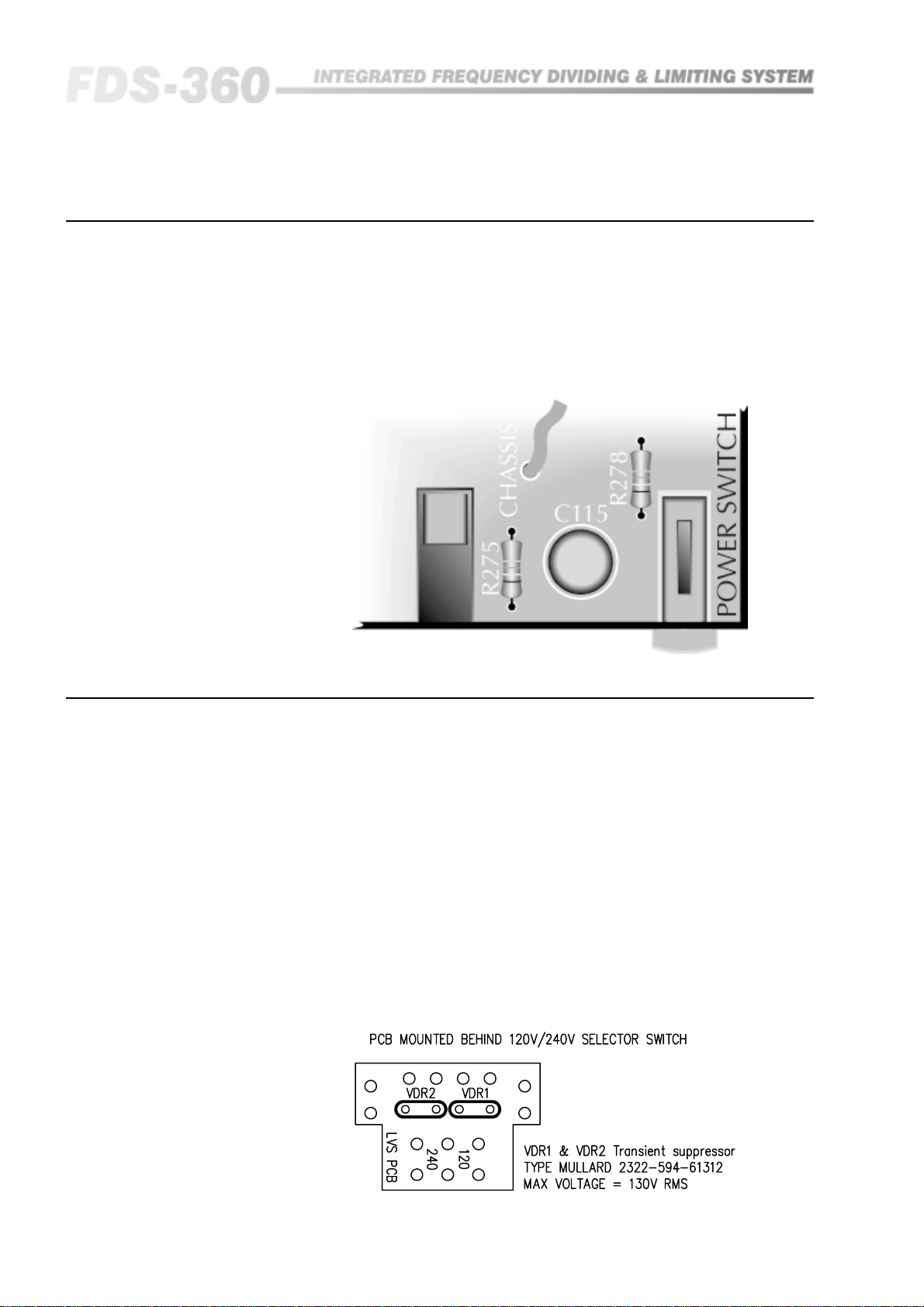
21.0 Electronic/Chassis Earth Link
In some installations it may be necessary to separate the electronic 0V from
the chassis and mains power earth to help in avoiding earth loops around the
unbalanced output connections. Should this become necessary, it is easily
achieved by removing a wire link inside the FDS-360. Figure 21.1 shows the
location of this wire link.
Fig 21.1 Wire Link
Location
22.0 Transient Suppressor Replacement
The primary of the mains transformer within the FDS-360 is protected against
high voltage spike interference by two voltage dependent resistors. These
provide a short circuit to voltage peaks in excess of their maximum rating.
Should the FDS-360 be inadvertently connected to 3 phase line/line voltages,
or to 240V when selected to 120V, or any other incorrect voltage, these
suppressors are likely to fail in a protective short circuit mode. This will be
demonstrated by repeated mains fuse failure when powering up the unit.
Even in this case of extreme overvoltage, the FDS-360 is protected against
failure, and the simple removal of these suppressors will allow the unit to be
used again. However, it is important that they are replaced as soon as
possible to ensure continued protection.
Figure 22.1 indicates the location and specification for the suppressors.
Fig 22.1 Suppressor
location
42
Page 43

23.0 Troubleshooting
Problem: No output
Solution: Is the MUTE switch depressed?
Is the mains power on? (See section 8.0)
Check the connections. See Fuse failure (below).
Do you have an input signal?
Is the SIGNAL LED on?
Check the input and output connections (See sections 9.0 & 10.0).
Are the power amplifiers switched on?
Problem: Excessive Hum, Intermittent sound
Solution: First check the connections on your input and output plugs (See sections 9.0 &
10.0). Unshielded cables, improperly wired connectors and damaged cables
are the most common cause of sound system hums and buzzes. Then refer to
sections 8.0.
Troubleshooting
Problem: Blown fuse
Solution: The mains supply fuse is unlikely to blow without an electronic fault being
present (See section 8.0). If the fuse blows again at switch on or after a short
interval, switch off the unit and arrange for servicing. The internal DC fuses
will only blow in the event of major fault condition. If they are visibly blown,
DO NOT OPERATE THE UNIT. Return it to be serviced.
43
Page 44

Glossary
24.0 Glossary
Active
Amplitude
Attack Time
Balanced
Breathing
Compressor
dB
Active electronic circuits are those which are capable of voltage and power
gain by using transistors and integrated circuits. Passive circuits are those
which use only capacitors, resistors, transformers, etc.
Refers to the voltage level or intensity of a signal, and is usually measured in
voltage or decibels.
The amount of time taken for the compressor or limiter to start gain reduction
once the input signal has exceeded the threshold level. This is usually
measured in micro or milliseconds (millionths or thousandths of a second).
A three wire connection in which two of the wires carry the signal
information, and the third acts as a shield tied to chassis ground. The two
signal lines are of opposite polarity at any given moment in time, and are of
equal potential with respect to ground. Balanced connections are used to
improve hum and noise rejection in system interconnections.
A term used to describe the fluctuations of background noise resulting from
the compressor action.
An electronic circuit which reduces its input to output gain as the input signal
increases above a predetermined threshold level.
A unit for expressing the ration between two signal levels for comparison
purposes. On its own it has no absolute level meaning. Rather, it is a
logarithmic ration used to express the differences between two amounts or
levels. Positive numbers indicate an increase, and negative ones a decrease.
Some useful ratios are:
44
dBm
dBu or dBv
dBV
+3dB = Double Power
+6dB = x 2 Voltage or x 4 Power
+10dB = x 3 Voltage or x 10 Power
+20dB = x 10 Voltage or x 100 Power.
The addition of 'm' after dB indicates an absolute scaling for the dB ratio.
Instead of a ratio, the dB becomes a measure of voltage. 0dBm = a power
level of 1 milliwatt into a load of 600 ohms. It is also loosely used to describe
signal voltage in 600 ohm circuits.
The addition of 'u' or 'v' after dB indicates an absolute scaling for the dB
ratio. 0dBu (or 0 dBv) = 778mV or 0.778 Volts, and it has no regard for power
or impedance. This term is widely used for expressing signal voltages in
modern audio equipment with high input impedances and low output
impedances.
The same scale as for dBu as before, except that 0dBV = 1.0 Volts.
Page 45

Distortion
Any modification of a signal which produces new frequency components not
presents in the original. Harmonic distortion refers to added frequencies that
are overtones to the fundamental frequency. Intermodulation distortion refers
to added frequencies that are sum and difference values derived from the
beating together of two frequencies.
Equalisation
Frequency
Frequency
Response
Gain Reduction
Headroom
Impedance
Level
Modification of the frequency response of an audio system, regardless of
level, for corrective or enhancement purposes.
The repetition of a waveform. The unit of frequency is Hz, and 1 cycle per
second is equal to 1Hz. The audio band is generally restricted to frequencies
of 20Hz to 20,000Hz (20kHz).
The equipment's relative gain compared to frequency. Generally expressed as
+/- a certain number of dBs from 20Hz to 20kHz.
The amount, in dBs, by which a compressor/limiters output has been reduced
in level with respect to its uncompressed level.
The amount, in dBs, above the normal operating level that can be used before
serious distortion commences.
The AC equivalent of resistance and measured in ohms. It indicates the
amount of drive required for an input, or the drive capability of an output, at a
given signal level.
The amplitude of a signal, measured in Volts or Decibels.
Line Level
Limiter
Octave
Ratio
Release Time
Threshold
Generally indicates a signal whose level is between -10 and +10dBu or -14 to
+6 dBV. Mic level refers to levels around -40dBu.
Similar to a compressor but harder acting, and generally used as a protection
device for audio systems.
A logarithmic unit for expressing frequency ratios. Positive values indicate an
increase and negative ones a decrease. One octave 'up' the scale is
equivalent to double the frequency. One octave 'down' is equivalent to half
the frequency.
The relationship between change in input level and resulting change in output
as a consequence of compressing or limiting.
The time required for a compressor or limiter to restore its gain to normal, after
the input signal has fallen below threshold.
The pre-settable level above which a compressor or limiter will commence to
gain reduce.
45
Page 46

Glossary
Transient
A sudden burst of energy in an audio signal which only lasts for a small period
of time relative to the rest of the signal. The level of a transient can often
reach 10 times or so the normal operating level of the audio equipment, and
may cause distortion.
Where output level is equal to input signal level.Unity Gain
46
Page 47

25.0 Specifications
Gain: 0dB standard. Optional +10dB to order.
Noise: 85dBm 20Hz to 20kHz unweighted.
Distortion: <0.5% THD up to +20dBm output, limiter cancelled.
Typically 0.0005% THD +6dBm output.
Filters: 24dB/OCT Linkwitz-Riley as standard.
Options include any 12, 18, 24dB/OCT filter type with user specified
frequencies preset by plug-cards.
Phase: Continually adjustable 0-180 degree at band corner frequency. Additional 180
degree using the polarity switch.
Inputs: 10k ohm electronically balanced.
Input Filter: 24dB/OCT 30Hz subsonic. Optional 15Hz. 18dB/OCT 26kHz ultrasonic.
Outputs: Unbalanced 50 milli-ohm current limited source to drive 600 ohm load.
Maximum level +20dBm.
Specifications
Limiter: Separate for each band with attack and release times scaled to suit. Limit
ratio >20:1. Threshold range adjustable in 0.5dM steps from +10dBv to 11dBv.
Indicators: Three LEDs to indicate presence of signal, onset of limiting and over-limiting.
Insertion Points: Channel sends: Output impedance 100 ohm to drive 10k ohm load to +20dBv.
Channel returns: Input impedance 10k ohm. Maximum level +20dBv
unbalanced.
Mains Supply: Switched 120V or 240V +10%-20% at 50-60Hz.
Power supply is designed with extended low-voltage tolerance to meet show
requirements.
Size: 482mm x 44mm x 228mm
19" x 1¾" x 9".
Weight: 4.5kg packed.
47
Page 48
Warranty Information
26.0 Warranty Information
This unit is warranted by BSS Audio to the original end user purchaser against
defects in workmanship and the materials used in its manufacture for a period
of one year from the date of shipment to the end user.
Faults arising from misuse, unauthorised modifications or accidents are not
covered under this warranty. No other warranty is expressed or implied.
If the unit is faulty it should be sent, in its original packaging, to the supplier
or your local authorised BSS Audio dealer with shipping prepaid.
You should include a statement listing the faults found. The unit’s serial
number must be quoted in all correspondence relating to a claim.
IMPORTANT
We recommend that you record your purchase information here for future
reference.
Dealer Name:
Dealer Address:
Post/Zip Code:
Dealer Phone No.:
Dealer Contact Name:
Invoice/Receipt No.:
Date of Purchase:
Unit Serial Number:
In keeping with our policy of continued improvement, BSS Audio reserves the
right to alter specifications without prior notice.
The FDS-360 was designed and developed by BSS Audio, Hertfordshire,
England.
48
Phone (+44) (0)1707 660667. Fax (+44) (0)1707 660755.
World Wide Web address: http://www.bss.co.uk
Page 49

Index
Index
15Hz Subsonic Filter 25
A
Auto Mute Cancel. See Rear Barrier
Strip
B
Band Insertion Points. See Rear
Barrier Strip
Bass shelving 35
Bell shape equaliser 34
Boost 34
C
Contents 3
Controls 16
Crossovers 6
Active 6
Passive 6
Cut 34
E
Earth Link 42
Electromagnetic Compatibility 2
Equalisation Options 31
Limiter Threshold Reference. See
Rear Barrier Strip
Limiter Threshold Switch. See Con-
trols
Limiters 22
Linkwitz-Riley 8
M
Mains Connection 1 3
Mains interference 35
Manual Version No. 2
Mode Switch. See Controls
Mono Low Switch. See Controls
Mute Switch. See Controls
O
On-axis symmetry. See Linkwitz-
Riley
Operational Modes 21
Outputs 14
P
Phase Adjustment 2 4
Phase Control. See Controls
Polarity Switch. See Controls
F
Filter Design 33, 40
Frequency Cards 1 9
Frequency Tables 27
Front Panel 10
Fusing. See Mains Connection
G
Getting to know the FDS-360 10
Glossary 44
Grounding. See Mains Connection
I
Inputs 14
Installation 12
Invisible slopes 8
L
Level Control. See Controls
Limiter
Adjustment 2 2
Limiter Cancel. See Rear Barrier
Strip
R
Racking 12
Rear Barrier Strip 20
Rear Panel 10
Rolloffs 7
S
Security 30
Signal LEDs. See Controls
Sources 14
Balanced 14
Unbalanced 14
Specifications 47
Supported Options 30
System Diagrams 25
T
Transient Suppressor Replacement42
Treble shelving 35
Troubleshooting 43
U
Unpacking 9
49
Page 50

Index
V
Voltage. See Mains Connection
W
Warranty 48
Wiring convention. See Inputs
WWW address 48
Z
Zero Phase difference 8
50
Page 51

User Notes
51
Page 52

User Notes
52
Page 53

53
Page 54

User Notes
54
 Loading...