

Bss FCS966 User Manual
FCS 966
User Manual
1
V 1.0 BV/JMK 30 April 1998
An example of this equipment has been tested and found to comply with the following European and
international Standards for Electromagnetic Compatibility and Electrical Safety:
Radiated Emissions (EU): EN55013 (1990) Associated Equipment
RF Immunity (EU): EN50082/1 (1992) RF Immunity, Fast Transients ESD
Mains Disturbance (EU): EN61000/3/2 (1995)
Electrical Safety (EU): EN60065 (1993)
Radiated Emissions (USA):FCC part 15 Class B
IMPORTANT SAFETY INFORMATION
DO NOT REMOVE COVERS. NO USER SERVICEABLE PARTS INSIDE, REFER SERVICING TO QUALIFIED
SERVICE PERSONNEL. THIS EQUIPMENT MUST BE EARTHED.
IT SHOULD NOT BE NECESSARY TO REMOVE ANY PROTECTIVE EARTH OR SIGNAL CABLE SHIELD
CONNECTIONS TO PREVENT GROUND LOOPS. ANY SUCH DISCONNECTIONS ARE OUTSIDE THE
RECOMMENDED PRACTISE OF BSS AUDIO AND WILL RENDER ANY EMC OR SAFETY CERTIFICATION
VOID.
For continued compliance with international EMC legislation ensure that all input and output cables are wired
with the cable screen connected to Pin 1 of the XLR connectors and/or the jack plug sleeve. The input XLR Pin
1, input jack socket sleeve and Combi-Con screen connectors are connected to the chassis via a low value
capacitor, providing high immunity from ground loops whilst ensuring good EMC performance.
Please read
We have written this manual with the aim of helping installers, sound engineers and musicians alike to get the
most out of the FCS 966. We recommend that you read this manual, particularly the section on installation,
before attempting to operate the unit.
We recommend that you read this manual, particularly the section on installation, before attempting to operate
the unit as there are a number of features that may not be apparent by casual use. The manual is split into two
main sections. The first contains quick reference information, regarding the functions and operation of the unit,
while the second covers a more general background to the uses and application of the FCS 966.
We welcome any comments or questions regarding the FCS 966 or other BSS products, and you may contact us
at the address or World Wide Web site given in the warranty section.
2

Contents
Contents
1.0 Mechanical installation 5
2.0 Unpacking 6
3.0 Mains Power Connection 6
3.1 Mains Power 6
4.0 Introduction 7
5.0 Audio Connections 10
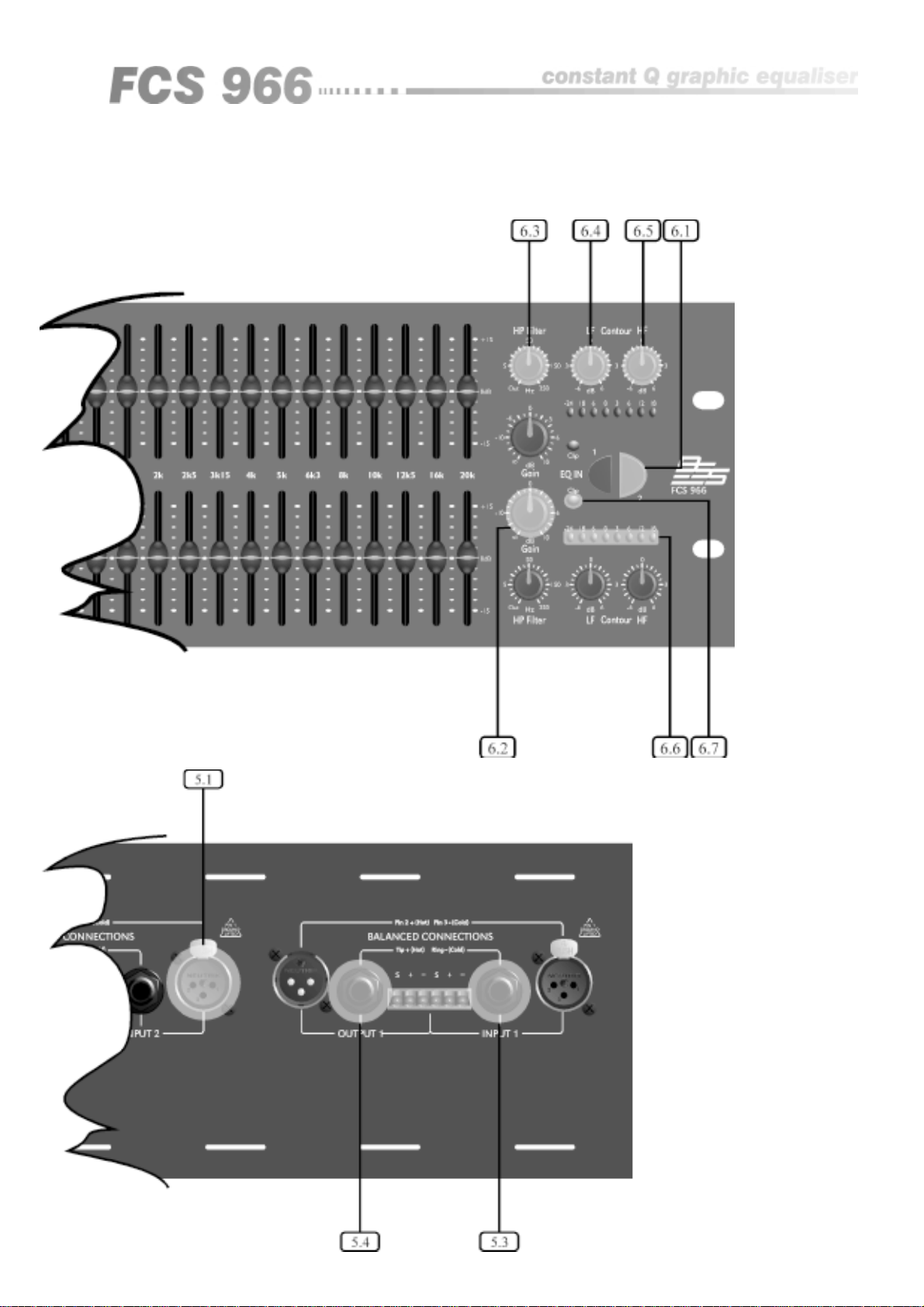
5.1 XLR Inputs 10
5.2 XLR Outputs 10
5.3 Jack Inputs 11
5.4 Jack Outputs 12
5.5 Combi-Con connectors 12
6.0 Control operations 14
6.1 Eq In 14
6.2 Gain 14
6.3 HP Filter 15
6.4 LF Contour 15
6.5 HF Contour 16
6.6 Output meter 16
6.7 Clip indicators 17
6.8 Frequency band sliders 17
7.0 General guide to equalisers 18
7.1 What is a graphic? 18
7.2 How do I use it? 18
7.3 What does constant Q mean? 19
3

Contents
8.0 Application examples 21
8.1 General Equalisation problem solving 21
8.2 Feedback reduction 22
8.3 Room equalisation 22
8.4 Uses for the HP Filter 23
8.5 Uses for the LF contour 24
8.6 Use for the HF contour 24
9.0 Warranty Information 25
10.0 Specifications 26
Index 27
User Notes 28
Spare Parts Information 31
4
1.0 Mechanical installation
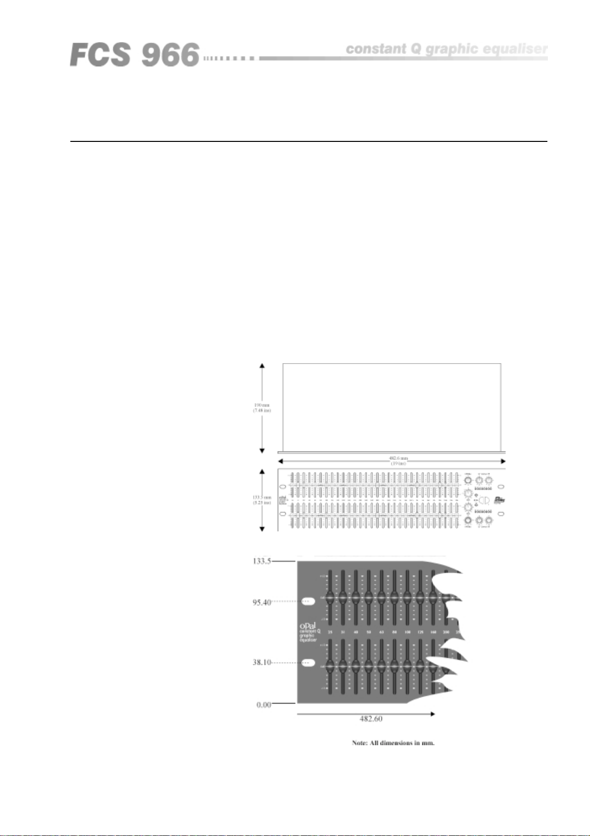
A vertical rack space of 3U (5 1/4" - 133.5mm high) is required, with a depth of
190mm, excluding connectors. Ventilation gaps are unnecessary.
If the unit is likely to undergo extreme vibration through extensive road
trucking and touring, the unit must be supported at the rear and/or sides to
lessen the stress on the front mounting flange. The necessary support can
generally be bought ready-built, as a rack tray, or the FCS 966 can be mounted
between other units. Damage caused by insufficient support is not covered by
the warranty. To prevent cosmetic damage to the front panel paint finish,
always use protective plastic cups under the rack mounting bolts.
As with any low-level signal processing electronics, it is best to avoid mounting
the FCS 966 next to a strong source of magnetic radiation or heat, for example,
a high power amplifier.
Mechanical Installation
Fig 1.1 Unit dimensions.
Fig 1.2 Rack
dimensions.
5

Unpacking
Mains Power Connection
2.0 Unpacking
As part of the BSS system of quality control, we check every product carefully
before packing to ensure that it reaches you in flawless condition.
Before you go any further, please check the unit for any physical damage and
retain the shipping carton and all relevant packing materials for use, should the
unit need returning.
In the event that damage has occurred, please notify your dealer immediately,
so that a written claim to cover the damages can be initiated. Check out
section 9.0; warranty information, for more info on the warranty, and also to
record your dealer details.
3.0 Mains Power Connection
3.1 Mains Power
WARNING! THIS APPLIANCE MUST BE EARTHED.
The FCS 966 must always be connected to a 3-wire earthed AC outlet. The
rack framework must also be connected to the same grounding circuit. The
unit must NOT be operated unless the power cables' EARTH (ground) wire is
properly terminated - this is important for personal safety as well as for proper
control over the system grounding.
The wires in the mains lead are colour coded in accordance with the following
code.
Green and Yellow......Earth
Blue......Neutral
Brown......Live
Those units supplied to the North American market will have an integral
moulded 3 pin connector which is provided to satisfy required local standards.
IMPORTANT: The FCS 966 is designed to use 50/60Hz AC power in one of
two voltage ranges, selectable with the mains voltage selector switch on the
rear of the unit. It is vital that the position of this switch is checked BEFORE
initial power up to ensure that it matches the local mains supply. Acceptable
input AC supply voltages range from:
115V switch position 90V to 132V
230V switch position 190V to 265V
The application of voltages outside these ranges may cause permanent damage
or erratic operation of the unit, and will invalidate the warranty.
The mains fuse carrier on the rear of the unit must be fitted with the correct
type and rating of fuse, depending on the position of the mains voltage selector
switch:
115V switch position T315mA fuse
230V switch position T200mA fuse
In the unlikely event of the mains fuse failing without good reason,
DISCONNECT THE UNIT FROM THE MAINS SUPPLY, and always replace
6

with the appropriately rated fuse (as specified previously) for continued
protection against damage and fire.
Note: For USA and Canadian users, the replacement fuse must be of an
identical UL rated type fuse for continued compliance with safety standards.
4.0 Introduction
The FCS 966 is a two channel graphic equaliser that provides a generous +/
-15dB of control range on each of 30 constant Q frequency bands. For
optimum performance, each filter band is arranged to be out of circuit if it's
sliders are left in the centre of its travel, and thus does not contribute
unnecessary noise or distortion.
In addition, a sweepable high pass filter, variable gain, and HF/LF contour
controls are provided for extra flexibility. Indication of level is provided by an
8 segment meter that reads input level when the unit is bypassed, and output
level when active. This allows accurate level matching of the equalised to
unequalised signal. Indication of overload is provided by a separate clip
indicator that simultaneously monitors the level at three critical internal points
to ensure that any overload does not go unnoticed.
Introduction
When bypassed, the FCS 966 connects the output directly to the input with a
high quality relay, ensuring that a signal passes even with a loss of AC power.
The relay drive also incorporates a power on delay and AC power loss
detector, ensuring that there is no possibility of on/off thumps being generated
by the unit.
For installation flexibility, XLR, Jacks and pluggable terminal block (combi-con)
connectors are provided as standard, with transformer isolation on both the
inputs and outputs available as an option. The mains lead is a standard
detachable IEC type.
7
The FCS 966
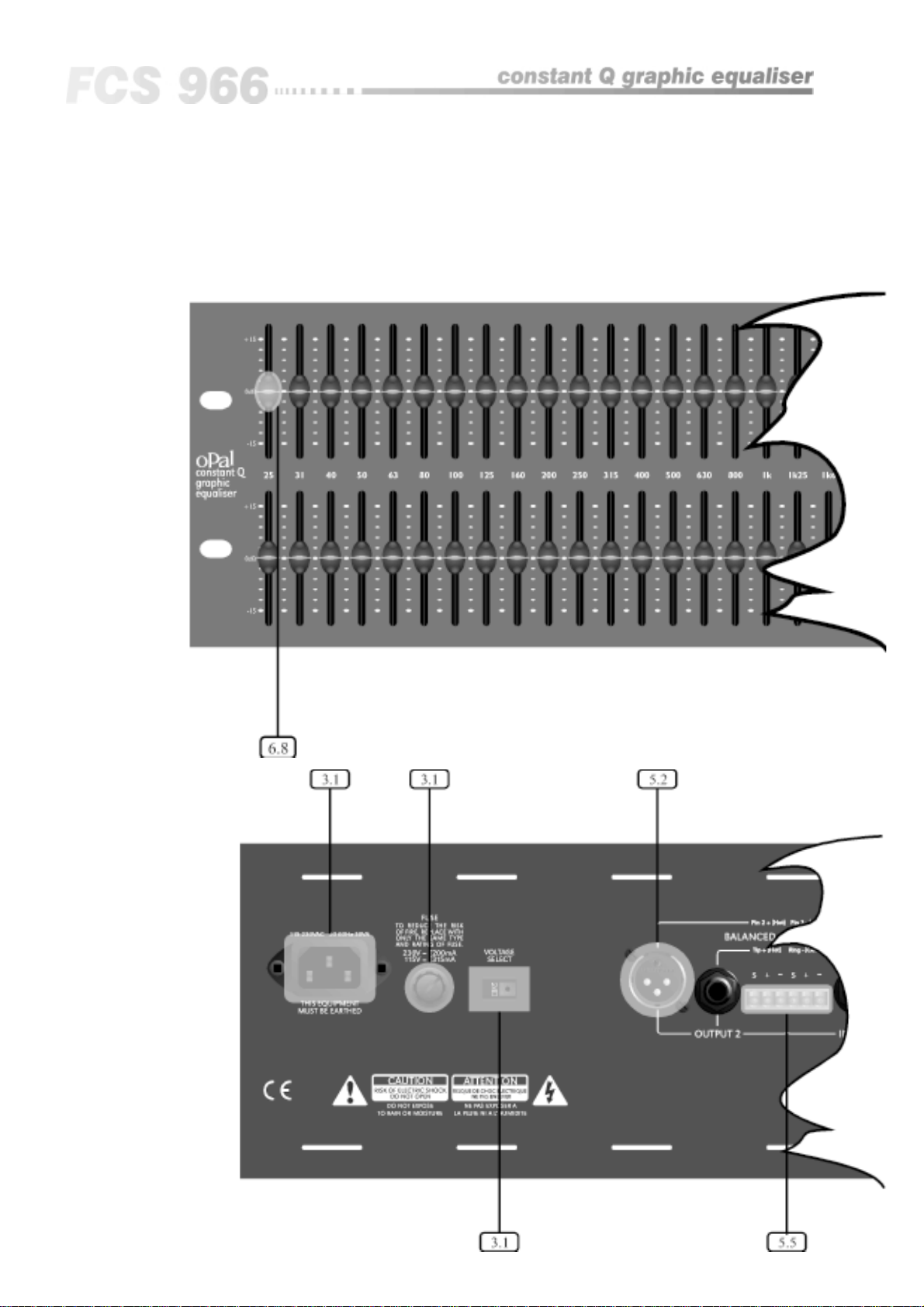
Fig 4.1 Front Panel
Fig 4.2 Rear Panel
8
All numbers in bubbles refer to
Section numbers.
9
 Loading...