

Page 1
installation and
start-up instructions
10 SEER 3 PHASE R-22
SPLIT SYSTEM
AIR CONDITIONER
NOTE: Read the entire instruction manual before starting the
installation.
This symbol → indicates a change since the last issue.
SAFETY CONSIDERATIONS
Improper installation, adjustment, alteration, service, maintenance,
or use can cause explosion, fire, electrical shock, or other
conditions which may cause death, personal injury, or property
damage. Consult a qualified installer, service agency, or your
distributor or branch for information or assistance. The qualified
installer or agency must use factory-authorized kits or accessories
when modifying this product. Refer to the individual instructions
packaged with the kits or accessories when installing.
Follow all safety codes. Wear safety glasses, protective clothing,
and work gloves. Use quenching cloth for brazing operations.
Have fire extinguisher available. Read these instructions thoroughly and follow all warnings or cautions included in literature
and attached to the unit. Consult local building codes and National
Electrical Code (NEC) for special requirements.
Recognize safety information. This is the safety-alert symbol
When you see this symbol on the unit and in instructions or
manuals, be alert to the potential for personal injury.
Understand the signal words DANGER, WARNING, and CAUTION. These words are used with the safety-alert symbol. DANGER identifies the most serious hazards which will result in severe
personal injury or death. WARNING signifies hazards which
could result in personal injury or death. CAUTION is used to
identify unsafe practices which may result in minor personal
injury or product and property damage. NOTE is used to highlight
suggestions which will result in enhanced installation, reliability,
or operation.
WARNING: ELECTRICAL SHOCK HAZARD
Failure to follow this warning could result in personal
injury or death.
Before installing, modifying, or servicing system, main
electrical disconnect switch must be in the OFF position.
There may be more than 1 disconnect switch. Lock out
and tag switch with a suitable warning label.
INSTALLATION RECOMMENDATIONS
NOTE: In some cases noise in the living area has been traced to
gas pulsations from improper installation of equipment.
1. Locate unit away from windows, patios, and decks where
unit-operation sound may disturb customer.
2. Ensure that vapor- and liquid-tube diameters are appropriate
to capacity of unit. (See Table 1.)
3. Run refrigerant tubes as directly as possible by avoiding
unnecessary turns and bends.
4. Leave some slack between structure and unit to absorb
vibration.
5. When passing refrigerant tubes through the wall, seal
opening with RTV or other pliable silicon-based caulk. (See
Fig. 2.)
561G
Cancels: II 561C-18-6 II 561G-30-1
3-06
.
6. Avoid direct tubing contact with water pipes, duct work,
floor joists, wall studs, floors, and walls.
7. Do not suspend refrigerant tubing from joists and studs with
a rigid wire or strap that comes in direct contact with tubing.
(See Fig. 2.)
8. Ensure that tubing insulation is pliable and completely
surrounds vapor tube.
9. When necessary, use hanger straps which are 1 in. wide and
conform to shape of tubing insulation. (See Fig. 2.)
10. Isolate hanger straps from insulation by using metal sleeves
bent to conform to shape of insulation.
CAUTION: UNIT DAMAGE HAZARD
Failure to follow this caution may result in equipment
damage or improper operation.
If ANY refrigerant tubing is buried, providea6in.
vertical rise at service valve. Refrigerant tubing lengths
up to 36 in. may be buried without further special
consideration. Do not bury more than 36 inches of
refrigerant tubing in the ground.
I. CHECK EQUIPMENT AND JOB SITE
A. UNPACK UNIT
Move to final location. Remove carton, taking care not to damage
unit.
B. INSPECT EQUIPMENT
File claim with shipping company prior to installation if shipment
is damaged or incomplete. Locate unit-rating plate on unit-corner
panel. It contains information needed to properly install unit.
Check rating plate to be sure unit matches job specifications.
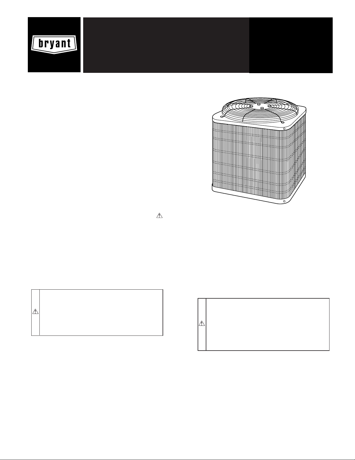
Fig. 1—Model 561G
INSTALLATION
A98524
—1—
Page 2
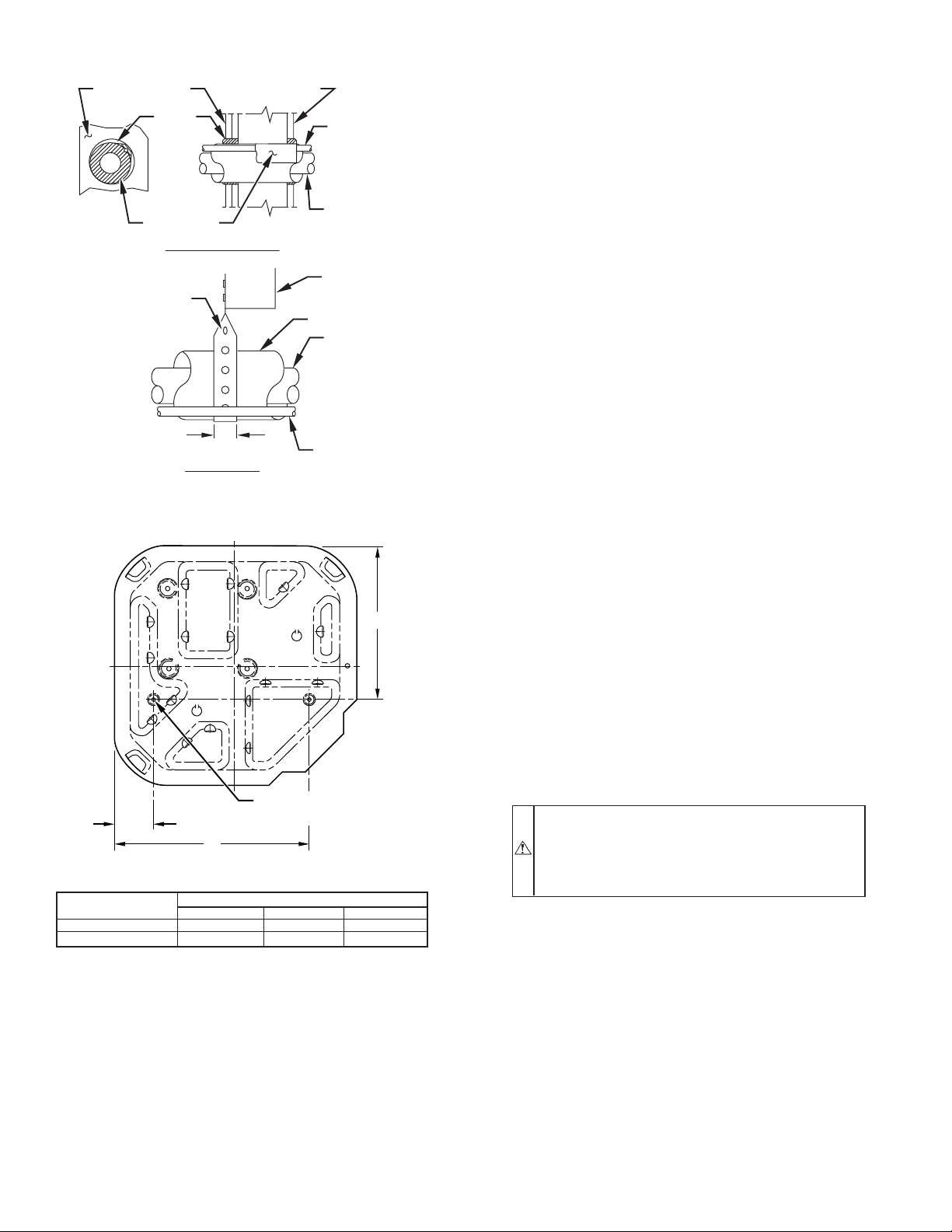
Avoid contact between tubing and structureNOTE:
OUTDOOR WALL INDOOR WALL
CAULK
LIQUID TUBE
unit and 48 in. above unit. For proper airflow, a 6-in. clearance on
1 side of unit and 12 in. on all remaining sides must be maintained.
Maintain a distance of 24 in. between units. Position so water,
snow, or ice from roof or eaves cannot fall directly on unit.
On rooftop applications, locate unit at least 6 in. above roof
surface. Place unit above a load-bearing wall and isolate unit and
tubing set from structure.
INSULATION
THROUGH THE WALL
JOIST
HANGER STRAP
(AROUND VAPOR
TUBE ONLY)
1″ MIN.
SUSPENSION
INSULATION
LIQUID TUBE
Fig. 2—Connecting Tubing Installation
VAPOR TUBE
VAPOR TUBE
C
A94028
IV. OPERATING AMBIENT
The minimum outdoor operating ambient in cooling mode is 55°F,
and the maximum outdoor operating ambient in cooling mode is
125°F.
V. CHECK INDOOR CHECK-FLO-RATER® PISTON (IF
REQUIRED) OR ADD TXV
Check indoor coil piston to see if it matches the required piston
shown on outdoor unit rating plate. If it does not match, replace
indoor coil piston with piston shipped with outdoor unit. The
piston shipped with outdoor unit is correct for any approved indoor
coil combination.
NOTE: If a TXV is to be installed on indoor unit, remove indoor
coil piston and follow Section VI.
VI. INSTALL TXV
IMPORTANT: If not factory installed, the TXV should be
mounted as close to the indoor coil as possible and in a vertical
upright position. Avoid mounting the inlet tube vertically down.
Valve is more susceptible to malfunction due to debris if inlet tube
is facing down. A factory-approved filter drier must be installed in
the liquid line.
A. Installing TXV in Place of Piston
1. Pump system down to 2 psig and recover refrigerant.
3
⁄8″D. (9.53) TIEDOWN
A
B
DIMENSIONS (IN.)
UNIT BASE
DIMENSIONS
22-1/2 x 22-1/2 3-11/16 18-1/8 14-3/8
30x30 6-1/2 23-1/2 20
TIEDOWN KNOCKOUT LOCATIONS
KNOCKOUTS (2) PLACES
A94199
ABC
Fig. 3—Mounting Unit to Pad
II. INSTALL ON A SOLID, LEVEL MOUNTING PAD
If conditions or local codes require the unit be attached to pad,
tie-down bolts should be used and fastened through knockouts
provided in unit base pan. Refer to unit-mounting pattern in Fig. 3
to determine base-pan size and knockout-hole location.
Arrange supporting members to adequately support unit and
minimize transmission of vibration to building. Consult local
codes governing rooftop applications.
III. CLEARANCE REQUIREMENTS
When installing, allow sufficient space for airflow, wiring, refrigerant piping, and service. Allow 30-in. clearance to service end of
2. Remove hex nut from piston body. Use backup wrench on
fan coils.
3. Remove and discard factory-installed piston. Be sure Teflon
seal is in place.
4. Reinstall hex nut. Finger tighten nut plus 1/2 turn.
NOTE: If the piston is not removed from the body, TXV will not
function properly.
CAUTION: EQUIPMENT DAMAGE HAZARD
Failure to follow this caution may result in equipment
damage or improper operation.
To prevent damage to the unit, use a brazing shield and
wrap TXV with wet cloth or use heat sink material.
5. Install TXV on indoor coil liquid line. Sweat swivel adapter
to inlet of indoor coil and attach to TXV outlet. Use backup
wrench to avoid damage to tubing or valve. Sweat inlet of
TXV, marked ″IN″ to liquid line. Avoid excessive heat
which could damage valve.
6. Install vapor elbow with equalizer adapter to suction tube of
line set and suction connection to indoor coil. Adapter has
a 1/4-in. male connector for attaching equalizer tube.
7. Connect equalizer tube of TXV to 1/4-in. equalizer fitting
on vapor line adapter.
8. Attach TXV bulb to horizontal section of suction line using
clamps provided. Insulate bulb with field-supplied insulation tape. See Fig. 4 for correct positioning of sensing bulb.
—2—
Page 3

TABLE 1—REFRIGERANT CONNECTIONS AND RECOMMENDED LIQUID- AND VAPOR-TUBE DIAMETERS (IN.)
1
UNIT
SIZE
030, 036 3/8 3/8 3/4 3/4
042-048 3/8 3/8 7/8 7/8
060 3/8 3/8 7/8 1-1/8
NOTES:
1. Tube diameters are for lengths up to 80 ft horizontal or 20 ft vertical differential. For tubing lengths greater than 80 ft, consult Residenital Split System Long-Line
Application Guidelines—Air Conditioners and Heat Pumps Using R-22 Refrigerant. Maximum liquid lines 3/8 in., including long-line applications.
2. Do not apply capillary-tube indoor coils to these units.
Connection Diameter Tube Diameter Connection Diameter Tube Diameter
LIQUID RATED VAPOR (UP TO 80 FT
)
CAUTION: UNIT DAMAGE HAZARD
Failure to follow this caution may result in unit component damage. To avoid equipment damage and/or loss of
performance remove indoor-coil piston if unit is to be
installed on system with a TXV-metering device.
Check outdoor unit piston. Remove retainer on liquid service valve
and check piston size with matching number listed on outdoor unit
rating plate.
VII. MAKE REFRIGERANT PIPING CONNECTIONS
Outdoor units may be connected to indoor section using accessory
tubing package or field-supplied refrigerant-grade tubing of correct size and condition. For tubing requirements beyond 80 ft,
consult Residential Split System Long-Line Application
Guideline—Air Conditioners and Heat Pumps Using R-22 Refrigerant. Connect tubing to fittings on outdoor unit vapor and liquid
service lines.
(See Table 1.)
If refrigerant tubes or the indoor coil are exposed to atmospheric
conditions for longer than 5 minutes they must be evacuated to 500
microns to eliminate contamination and moisture in system.
A. OUTDOOR UNIT CONNECTED TO FACTORYAPPROVED INDOOR UNIT
Outdoor unit contains correct system-refrigerant charge for operation with indoor unit of same size when connected by 15 ft of
field-supplied or factory accessory tubing. Check refrigerant
charge for maximum efficiency.
B. SWEAT CONNECTION
Be sure field wiring complies with local and national fire, safety,
and electrical codes, and voltage to system is within limits shown
on unit-rating plate. Contact local power company for correction of
improper voltage. See unit rating plate for recommended circuit
protection device.
NOTE: Operation of unit on improper line voltage constitutes
abuse and could affect unit reliability. See unit-rating plate. Do not
install unit in system where voltage or phase imbalance (3 phase)
may fluctuate above or below permissible limits.
NOTE: Use copper wire only between disconnect switch and
unit.
NOTE: Install branch-circuit disconnect of adequate size per
NEC to handle unit-starting current. Locate disconnect within sight
from and readily accessible from unit, per Section 440-14 of NEC.
A. ROUTE GROUND AND POWER WIRES
Remove access panel to gain access to unit wiring. Extend wires
from disconnect through power wiring hole provided and into
unit-control box.
WARNING: ELECTRICAL SHOCK HAZARD
Failure to follow this warning could result in personal
injury and or death. The unit cabinet must have an
uninterrupted or unbroken ground to minimize personal
injury if an electrical fault should occur. The ground may
consist of electrical wire or metal conduit when installed
in accordance with existing electrical codes.
B. CONNECT GROUND AND POWER WIRES
Connect ground wire to ground connection in control box for
safety. Connect power wiring to contactor as shown in Fig. 4.
CAUTION: UNIT DAMAGE HAZARD
Failure to follow this caution may result in unit component damage. To avoid valve damage while brazing,
service valves must be wrapped in a heat sink material,
such as a wet cloth.
Use refrigerant grade tubing. Service valves are closed from
factory and ready for brazing. After wrapping service valve with a
wet cloth, tubing set can be brazed to service valve using industry
accepted methods and materials. Consult local code requirements.
Refrigerant tubing and indoor coil are now ready for leak testing.
This check should include all field and factory joints.
VIII. MAKE ELECTRICAL CONNECTIONS
WARNING: ELECTRICAL SHOCK AND EXPLO-
SION HAZARD
Failure to follow this warning could result in personal
injury, death and or property damage. Do not supply
power to unit with compressor terminal-box cover removed.
—3—
DISCONNECT
PER N.E.C. AND/OR
LOCAL CODES
CONTACTOR
FIELD POWER
WIRING
3 PHASE ONLY
FIELD GROUND
WIRING
BLUE
GROUND
LUG
A94025
Fig. 4—Line Power Connections
C. CONNECT CONTROL WIRING
Route 24v control wires through control wiring grommet and
connect leads to control wiring. (See Fig. 6.)
Use No. 18 AWG color-coded, insulated (35°C minimum) wire. If
thermostat is located more than 100 ft from unit, as measured
along the control voltage wires, use No. 16 AWG color-coded wire
to avoid excessive voltage drop.
Page 4

Use furnace transformer, fan-coil transformer, or accessory transformer for control power, 24v/40va minimum.
NOTE: Use of available 24v accessories may exceed the minimum 40va power requirement. Determine total transformer loading and increase the transformer capacity or split the load with an
accessory transformer as required.
IX. COMPRESSOR CRANKCASE HEATER
1. When equipped with a crankcase heater, energize heater a
minimum of 24 hr before starting unit. To energize heater
only, set thermostat to OFF mode and close electrical
disconnect to outdoor unit.
A crankcase heater is required if refrigerant tubing is longer than
80 ft.
X. INSTALL ELECTRICAL ACCESSORIES
Refer to individual instructions packaged with kits or accessories
when installing.
XI. START-UP
CAUTION: PERSONAL INJURY HAZARD
Failure to follow this caution may result in personal
injury.
Service valve gage ports are equipped with Schrader
valves. Wear safety glasses and gloves when handling
refrigerant.
for compressor operation. (See Fig. 5 and Table 2.) If the phasing
is correct, circuit R-Y energizes contactor, starting outdoor fan
motor and compressor circuit. R-G energizes indoor unit blower
relay, starting indoor blower motor on high speed.
NOTE: If the phasing is incorrect, the contactor will not be
energized. To correct the phasing, interchange any two of the three
power connections on the field side.
A00010
Fig. 5—3-Phase Monitor Control
1. Fully open liquid and vapor service valves.
2. Unit is shipped with valve stem(s) front seated (closed) and
caps installed. Replace stem caps after system is opened to
refrigerant flow. Replace caps finger-tight and tighten an
additional 1/12 turn with wrench.
3. Close electrical disconnects to energize system.
4. Set room thermostat at desired temperature. Be sure set
point is below indoor ambient temperature.
5. Set room thermostat to COOL and fan control to ON or
AUTO mode. Operate unit for 15 minutes. Check systemrefrigerant charge. (See Check Charge.)
WARNING: PERSONAL INJURY AND ENVIRNOMENTAL HAZARD
Failure to follow this warning could result in personal
injury or death. Relieve pressure and recover all refrigerant before system repair or final unit disposal. Use all
service ports and open all flow control devices, including
solenoid valves.
CAUTION: UNIT DAMAGE HAZARD
Failure to follow this caution may result in unit component damage.
• 3-phase scroll compressors are rotation sensitive.
• A flashing LED on phase monitor indicates reverse
rotation. (See Fig. 5 and Table 2.)
• This will not allow contactor to be energized.
• Disconnect power to unit and interchange 2 field
wiring leads on unit contactor.
A. SEQUENCE OF OPERATION
Turn on power to indoor and outdoor units. Transformer is
energized.
On a call for cooling, thermostat makes circuits R-Y and R-G.
Three phase models with scroll compressors, are equipped with a
phase monitor to detect if the incoming power is correctly phased
TABLE 2—PHASE MONITOR LED INDICATORS
LED STATUS
OFF No call for compressor operation
FLASHING Reversed phase
ON Normal
When thermostat is satisfied, its contacts open, de-energizing
contactor and blower relay. Compressor and motors stop.
If indoor unit is equipped with an off delay circuit, the indoor
blower can run an additional 120 sec to increase system efficiency.
XII. CHECK CHARGE
UNIT CHARGE
Factory charge is shown on unit rating plate. Charge procedure is
shown on wiring/charging label locate on unit.
CAUTION: UNIT DAMAGE HAZARD
Failure to follow this caution may result in unit component damage. Compressor damage may occur if system is
overcharged.
CAUTION: ENVIRNOMENTAL HAZARD
Failure to follow this caution may result in environmental
damage and fines. Federal regulations require that you do
not vent refrigerant to the atmosphere. Recover during
system repair or final unit disposal.
A. Cooling Only Procedure—Indoor unit equipped with
piston, superheat method
Factory charge is shown on unit rating plate. To check charge in
cooling mode, refer to Cooling Only Procedure on unit wiring and
charging label.
NOTE: If superheat or subcooling charging conditions are not
favorable, charge must be weighed in accordance with unit rating
plate ± 0.6 oz/ft of 3/8-in. liquid line above or below 15 ft
respectively.
—4—
Page 5

B. Cooling Only Procedure—Indoor unit equipped with
TXV—Subcooling Method
Factory charge and subcooling are shown on unit information
plate. To check charge, follow the procedure below.
NOTE: If subcooling charging conditions are not favorable,
charge must be weighed in accordance with unit rating plate, ±0.6
oz/ft. of 3/8-in. liquid line above or below 15 ft, respectively.
Favorable conditions fall within the ranges given on the charging
chart on the outdoor unit plate.
EXAMPLE:
To calculate additional charge required for a 25-ft. line set; 25 ft 15 ft = 10 ft X 0.6 oz/ft=6ozofadditional charge.
This system requires charging by the subcooling method.
1. Operate unit a minimum of 10 minutes before checking
charge.
2. Measure liquid service valve pressure by attaching an
accurate gauge to service port.
3. Measure liquid line temperature by attaching an accurate
thermistor type of electronic thermometer to liquid line near
outdoor coil.
4. Refer to unit rating plate for required subcooling temperature.
5. Refer to Table 3. Find the point where required subcooling
temperature intersects measured liquid service valve pressure.
6. To obtain required subcooling temperature at the specific
liquid line pressure, add refrigerant if liquid line temperature is higher than indicated or reclaim refrigerant if
temperature is lower. Allow a tolerance of ±3°F.
NOTE: In long-line applications, See the Residential Split System Long-Line Application Guideline for special charging requirements.
CARE AND MAINTENANCE
For continuing high performance and to minimize possible equipment failure, it is essential that periodic maintenance be performed
on this equipment.Consult your servicing contractor or Owner’s
Manual for proper frequency of maintenance. Frequency of
maintenance may vary depending upon geographic areas, such as
coastal applications.
A/C
THERMOSTAT
Typical
FURNACE
AIR
CONDITIONER
Leave Owner’s Manual with homeowner. Explain system operation and maintenance procedures outlined in manual.
TABLE 3—REQUIRED SUBCOOLING TERMPERATURE
(°F)
LIQUID
PRESSURE AT
SERVICE VALVE
(PSIG) 5 10 15 20
134 71 66 61 56
141 74 69 64 59
148 77 72 67 62
156 80 75 70 65
163 83 78 73 68
171 86 81 76 71
179 89 84 79 74
187 92 87 82 77
196 95 90 85 80
205 98 93 88 83
214 101969186
223 104999489
233 107 102 97 92
243 110 105 100 95
253 113 108 103 98
264 116 111 106 101
274 119 114 109 104
285 122 117 112 107
297 125 120 115 110
309 128 123 118 113
321 131 126 121 116
331 134 129 124 119
346 137 132 127 122
359 140 135 130 125
REQUIRED SUBCOOLING TERMPERATURE (°F)
A/C
THERMOSTAT
Typical
FAN COIL
AIR
CONDITIONER
24 VAC HOT
24 VAC COM
HEAT STAGE 1
COOL STAGE 1
INDOOR FAN
R
C
W/W1
Y/Y2
G
R
C
W
Y
G
C
24 VAC HOT
24 VAC COM
HEAT STAGE 1
COOL STAGE 1
INDOOR FAN
R
C
W/W1
Y/Y2
G
R
C
W2
G
Fig. 6—Generic Wiring Diagram
(See Thermostat Installation Instructions for wiring specific unit combinations)
—5—
C
A02326
Page 6

© 2006 Bryant Heating & Cooling Systems 7310 W. Morris St. Indianapolis, IN 46231
—6—
Printed in U.S.A. Catalog No. II 561G-30-1
 Loading...