

Page 1
QUANTUM PLUS 13 SEER
650A (60 Hz)
HEAT PUMP WITH
PURON™ REFRIGERANT
The Quantum Plus line of split-system outdoor units has been
expanded to include the Model 650A 13 SEER heat pump
(with efficiencies up to 14.5 SEER). Homeo wners will appreciate the Quantum Plus with Puron Refrigerant because of its
efficiency, environmental soundness and its availability for
years to come.
Another benefit of the Quantum Plus is the durability of the
scroll compressor. Model 650A has received certifications
from UL, c-UL, ARI, CEC, and CSA-EEV. The 650A is also
approved by Energy Star
Seal for efficiency and environmental soundness.
REFRIGERANT —The environmentally sound refrigerant
used in the 650A is Puron. This advanced refrigerant contains no chlorine which can contribute to ozone depletion in
the atmosphere, so it’s a smart choice for homeowners who
are concerned with protecting our environment, now and for
future generations. And it’s a smart choice for anyone interested in high-efficiency cooling.
RELIABLE BUILT-IN COMPONENTS —All units include a
suction line accumulator that minimizes the amount of liquid
refrigerant that reaches the compressor; a high-pressure
switch for high-pressure protection; a low-pressure switch for
loss of charge protection; and a liquid-line filter drier to
remove any moisture or foreign matter from the system. A
crankcase heater is standard on the 048 and 060 sizes.
COMPRESSOR PROTECTION —Each scroll compressor
motor is protected with internal temperature and currentsensitive overloads. For improved serviceability each compressor is equipped with a compressor terminal plug.
UNIT DESIGN —Copper tube, enhanced aluminum fin coil
is designed for strong heat transfer. Vertical air discharge
carries sound and hot condenser air up and away from
adjacent patio areas and foliage. Heat pump style base pan
is popular for its easy removal of water, dirt, and leaves.
AeroQuiet System (AQS)
The
to achieve ultra-low sound ratings.
Aerocoustic Design featuring the Aeromax opening and
SM
for energy efficiency and by Green
FEATURES
consists of 4 design features
Sizes 024 thru 060
wire dome top results in quieter and more efficient operation.
Energy-Efficient Fan and Fan Motor provide a slower fan
operation, thus reducing noise and improving efficiency.
Sound Hood muffles noise from operation.
Discharge Muffler minimizes low frequency sound and
pressure pulsation generated by compressor discharge gas.
WEATHER-PROTECTIVE CABINET —Steel is galvanized
and coated with a layer of zinc phosphate. A layer of modified
polyester powder is then applied and baked on, providing
each unit with a durable finish that will last for man y years.
All screws on cabinet exterior are coated for a long-lasting,
rust-resistant, quality appearance.
COIL PROTECTION —The DuraGuard coil protector, made of
a 12 gage coated steel wire grid with vertical 3/8-in. spacing, is
designed to help protect the coil from inclement weather, vandalism, and incidental damage. It provides protection while not
restricting airflow and maintaining ease of coil inspection and
cleaning.
EASY SERVICEABILITY —One access panel provides
access to electrical controls and compressor. Removal of
wire dome gives access to fan motor and removal of the top
gives access to the coil.
WIDE RANGE OF SIZES —Available in 6 nominal sizes from
024 through 060 to meet the needs of residential and light
commercial applications.
LIMITED WARRANTY —Standard 1-year limited warranty on
parts, with an additional 9-year limited warranty on compressor .
TOTALLY ENCLOSED FAN MOTOR —Means greater reli-
ability under adverse weather conditions and dependable
performance for many years. Permanent split-capacitor-type
motors provide more economical operation.
DEFROST CONTROL BOARD —Incorporates a built-in
5-minute compressor time-delay relay, defrost relay, defrost
timer, and low-voltage terminal board. The defrost control is a
time/temperature initiation/termination control, which includes
3 field-selectable time periods of 30, 50, and 90 minutes.
APPLICATION VERSATILITY —Due to PressureGuard™
the 650A can be combined with a wide variety of evaporator
coils and blower packages to provide quiet, dependable
comfort. The 650A can be installed on a roof or at ground
level on a slab.
EXTERNAL SERVICE VALVES —Both service valves are
brass, back seating type with sweat connections. Valves are
externally located so refrigerant tube connections can be
made quickly and easily. Each valve has a service port for
ease of checking operating refrigerant pressures.
THERMOSTATIC EXPANSION VALVE (TXV) —This unit
must be installed with a Puron™ approved TXV on the
indoor coil. The FX4 and FV4 fan coils come factory
equipped with Puron TXVs. When installed with these fan
coils, no further change is required. For any other coil
combination, the approved field accessory Puron TXV
must be installed. For applications with fan coils such as the
FC4 and FK4 which have R-22 TXVs, the R-22 TXV must be
replaced with the approved field accessory Puron TXV.
ELECTRICAL RANGE —All units are offered in 208/230v
single phase only.
Form No. PDS 650A.24.2
Page 2
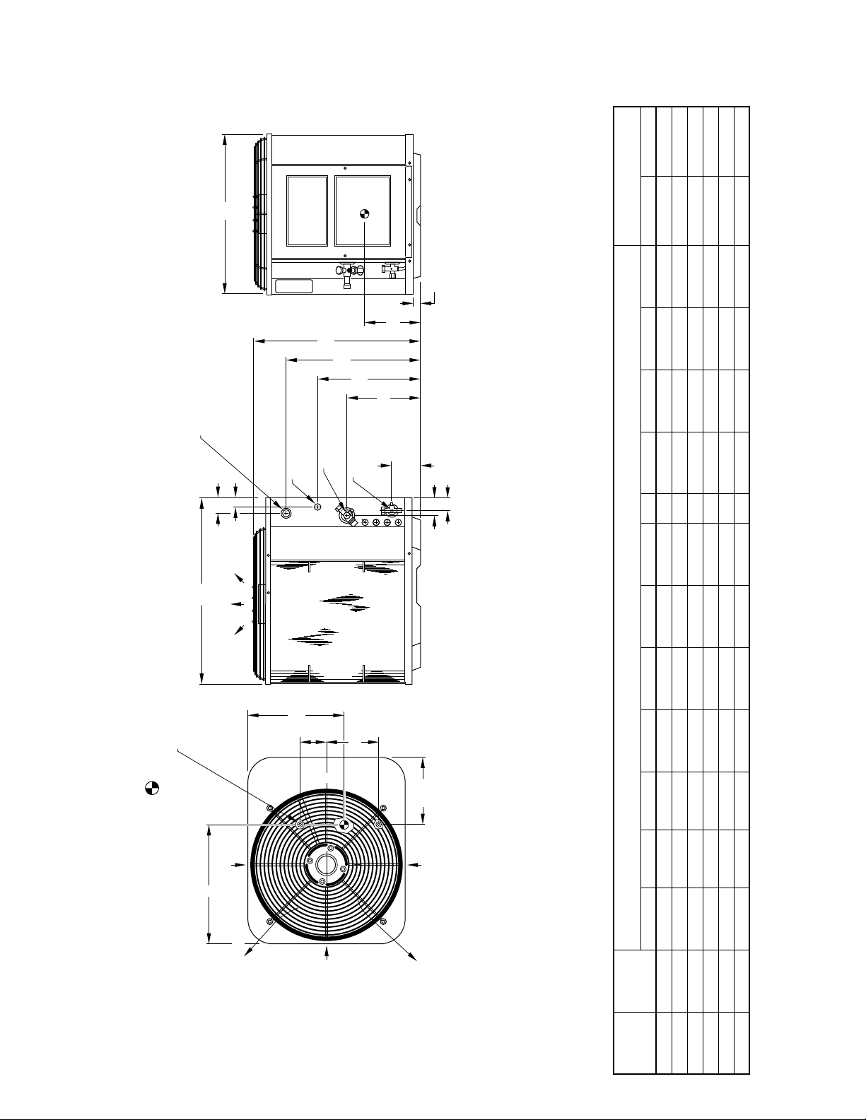
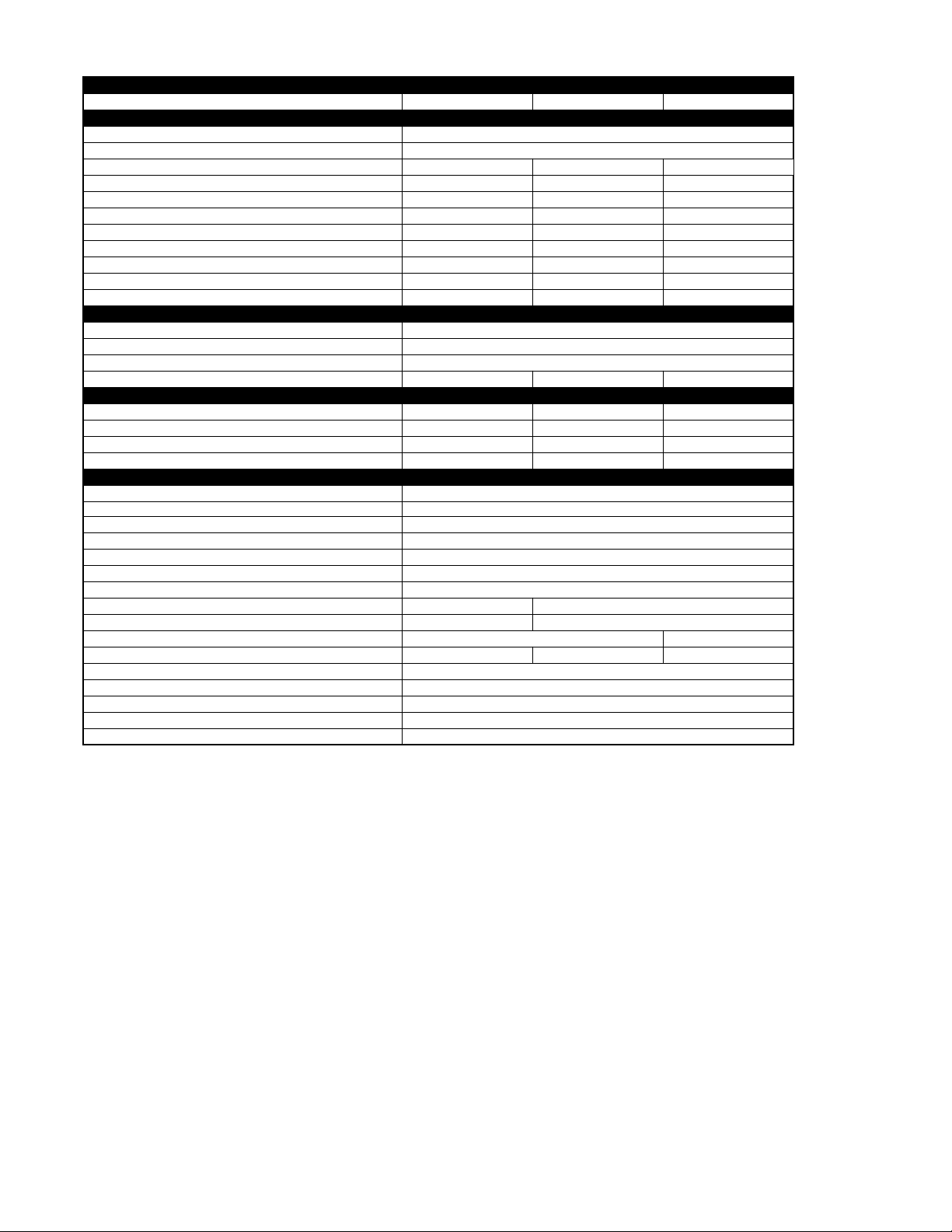
DIMENSIONS
B
ACCESS
DIA (22.22)
/8 IN.
7
DIA (34.92) KNOCKOUT
/8 IN.
1
DIA KNOCKOUT
/8 IN.
3
FIELD POWER SUPPLY CONN
HOLE WITH 1
AND 1
FIELD CONTROL
SUPPLY CONN
"
"
/16
/2
9
1
1
2
C
PANEL
A
DIA HOLE
DIA SUCTION
LINE CONN
H
/8 IN.
7
G
F
DIA LIQUID
/8 IN.
3
LINE CONN
A94148
PAD DIMENSIONS
MINIMUM MOUNTING
"
/4
1
1
M
"
/2
1
10
"
"
4
/4
3
1
N
AIR DISCHARGE
DIA (9.5) TIEDOWN KNOCKOUTS
/8 IN.
3
(2) PLACES IN BASEPAN
clearance to service end of unit, 48 in. above unit, 6 in. on one side, 12 in. on remaining side,
and 24 in. between units for proper airflow.
Minimum outdoor operating ambient in cooling mode is 55°F (unless low ambient control is used) max 125°F.2.
Maximum outdoor operating ambient in heating mode is 66°F.3.
Series designation is the 14th position of the unit model number.4.
1. Allow 30 in.
Center of gravity .5.
AIR IN
L
K
D
E
L
C
"
/16
3
8
AIR IN
NOTES:
AIR DISCHARGE
AIR IN
AIR DISCHARGE
DIMENSIONS (IN.)
UNIT DIMENSIONS
A B C D E F G H K L M N Support Feet Snow Stand
—2—
SIZE SERIES
UNIT
024 A,C 39-13/16 30 33 5-1/16 9-11/16 27-15/16 34-3/8 5/8 15-7/8 14-3/8 14-1/4 2-15/16 26 x 32 31 x 35
030 A,C 33-13/16 30 33 5-1/16 9-11/16 21-15/16 28-3/8 3/4 14 13-1/8 13-3/4 2-15/16 26 x 32 31 x 35
036 A,C 27-13/16 30 33 5-1/16 9-11/16 15-15/16 22-3/8 3/4 16-1/8 14-1/8 13-1/4 2-15/16 26 x 32 31 x 35
042 A,C 27-13/16 30 33 5-1/16 9-11/16 15-15/16 22-3/8 7/8 16-1/4 14 13-1/8 2-15/16 26 x 32 31 x 35
048 A,C 39-13/16 30 33 5-1/16 9-11/16 27-15/16 34-3/8 7/8 16-1/4 14-1/4 14-1/2 2-15/16 26 x 32 31 x 35
060 B,C 39-13/16 30 33 5-1/16 9-11/16 27-15/16 34-3/8 7/8 16 13-3/4 14 2-15/16 26 x 32 31 x 35
Page 3
RECOMMENDED TUBE DIAMETERS
LIQUID TUBE DIAMETER (IN.) VAPOR TUBE DIAMETER (IN.)
UNIT
SIZE
0 to 50 Ft
Tube Length Alternate
0 to 50 Ft
Tube Length Alternate
RST*
(Not Permitted)
024 3/8 3/8 5/8 3/4 ACR 3/4
030 3/8 3/8 3/4 7/8 1-1/8
036 3/8 3/8 3/4 7/8 1-1/8
042, 048 3/8 3/8 7/8 7/8 3/4 and 1-1/8
060 3/8 3/8 1-1/8 7/8 3/4
* RST—Refrigeration Service Tubing, standard refrigerant grade tubing.
NOTES:
1. Tube diameters are for lengths up to 50 ft. For tubing lengths greater than 50 ft, consult the Application Guideline and Service Manual for Residential SplitSystem Air Conditioners and Heat Pumps using Puron Refrigerant.
2. Refrigerant tubes and indoor coils must be evacuated to 500 microns to minimize contamination and moisture in the system.
METERING DEVICE
UNIT SIZE SERIES OUTDOOR PISTON INDOOR TXV*
024 A,C 46 KSATX0201HSZ 11
030 A,C 52 KSATX0201HSZ 9
036 A,C 57 KSATX0301HSZ 9
042 A,C 59 KSATX0301HSZ 11
048 A,C 61 KSATX0401HSZ 10
060 B,C 73 KSATX0501HSZ 12
* TXV must be installed when indoor coil is not equipped with a Puron approved TXV. TXV listed is for any approved coil combination. All TXVs are Puron spe-
cific bi-flow hard shutoff.
REQUIRED SUBCOOLING
(°F)
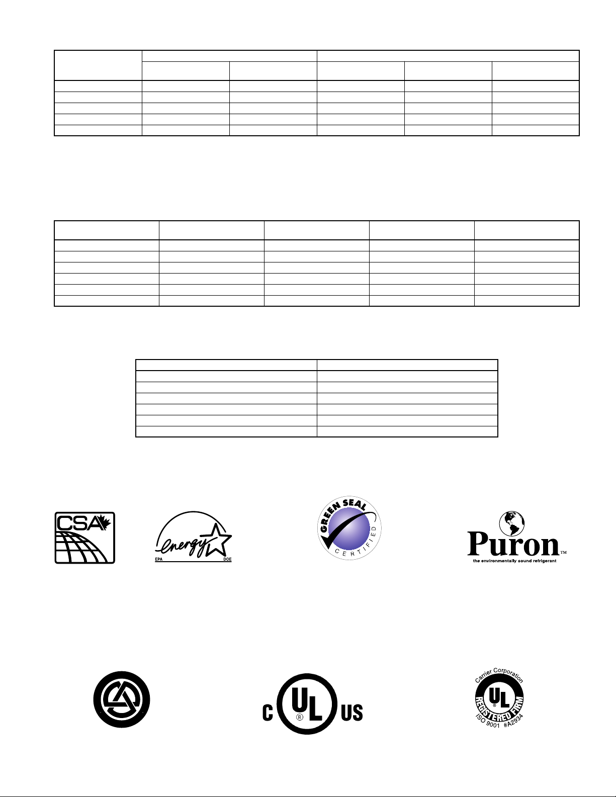
SOUND RATING (dBA)
UNIT SIZE–SERIES SOUND RATING
024-A,C 72
030-A,C 74
036-A,C 76
042-A,C 76
048-A,C 78
060-B,C 78
As an ENERGY STAR
partner, Bryant Heating &
Cooling Systems has
determined that this product meets the ENERGY
STAR guidelines for
energy efficiency.
SM
Meets GREEN SEAL Environmental Criteria
for high energy efficiency, low noise, and
recycled packaging. Does not use an oz one
depleting substance during manufacturing,
or as a refrigerant.
T
O
D
E
A
I
R
F
I
I
T
A
R
S
E
C
R
E
R
U
T
C
A
F
U
N
A
M
A
R
C
O
A
M
I
R
C
P
O
Y
R
A
T
I
N
U
I
S
L
N
D
Y
I
T
I
N
I
O
G
N
I
N
W
G
I
T
E
T
H
T
Q
N
U
E
I
P
M
0
1
2
D
A
R
N
A
D
CERTIFICATION APPLIES ONLY
WHEN THE COMPLETE SYSTEM
IS LISTED WITH ARI.
REGISTERED QUALITY SYSTEM
—3—
Page 4
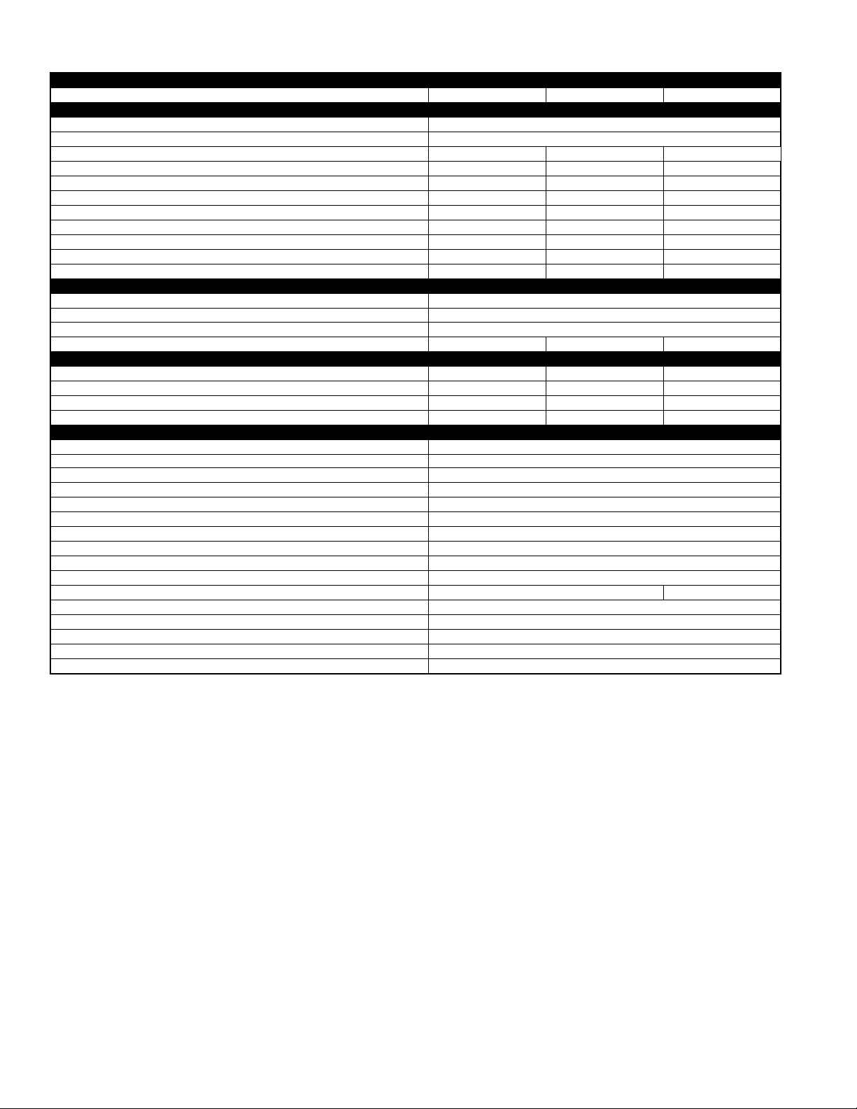
SPECIFICATIONS
UNIT SIZE-SERIES 024-A,C 030-A,C 036-A,C
Operating Weight (Lb) 214 205 217
ELECTRICAL
Unit Volts—Hertz—Phase 208/230—60—1
Operating Voltage Range* 187—253
Compressor Rated Load Amps 15.1 14.7 15.4
Compressor Locked Rotor Amps 61.0 72.5 83.0
Condenser Fan Motor—Full Load Amps 0.8 1.1 1.1
Minimum Unit Ampacity for Wire Sizing 19.7 19.5 20.4
Minimum Wire Size (60°C Copper) (AWG)† 14 14 12
Minimum Wire Size (75°C Copper) (AWG)† 14 14 12
Maximum Wire Length (60°C) (Ft)‡ 39 39 60
Maximum Wire Length (75°C) (Ft)‡ 37 37 57
Maximum Branch Circuit Fuse Size** 30 30 30
COMPRESSOR & REFRIGERANT
Compressor Manufacturer Copeland
Compressor T ype Scroll
Refrigerant T ype Puron
Refrigerant Amount (Lb)†† 7.18 6.63 8.87
OUTDOOR COIL & FAN
Coil Face Area (Sq Ft) 18.18 15.15 12.12
Fins per In.—Rows—Circuits 25—1—2 25—1—3 20—2—3
Fan Motor—HP & RPM 1/8 and 825 1/5 and 825 1/5 and 825
Rated Airflow (CFM) 2400 2800 2800
OPTIONAL EQUIPMENT
Support Feet—4 In. (4) KSASF0101AAA
Snow Stand—18 In. KHASS0206MPK
Time Delay Relay KAA TD0101TDR
Interface Control (Energy Minder)‡‡ KHAIC0101AAA
Service Alarm*** KHASA0101AAA
Outdoor Thermostat KHAOT0301FST
Secondary Outdoor Thermostat KHAOT0201SEC
Crankcase Heater KAACH1201AAA
Start Assist—Capacitor/Relay Type KSAHS1501AAA
Start Assist—PTC Type Standard
Bi-Flow TXV (Hard Shutoff) KSATX0201HSZ KSATX0301HSZ
Filter Drier (Suction Line) KH45LG140 (RCD)
Evaporator Freeze Thermostat††† KAAFT0101AAA
Isolation Relay††† KHAIR0101AAA
Liquid-Line Solenoid Valve (LSV) KHALS0401LLS
Low-Ambient Pressure Switch KSALA0301410
See notes on page 5.
—4—
Page 5
SPECIFICATIONS Continued
UNIT SIZE-SERIES 042-A.C 048-A,C 060-B,C
Operating Weight (Lb) 218 266 295
ELECTRICAL
Unit Volts—Hertz—Phase 208/230—60—1
Operating Voltage Range* 187—253
Compressor Rated Load Amps 21.1 20.5 27.6
Compressor Locked Rotor Amps 104.0 109.0 158.0
Condenser Fan Motor—Full Load Amps 1.1 1.4 1.4
Minimum Unit Ampacity for Wire Sizing 27.5 27.0 35.9
Minimum Wire Size (60°C Copper) (AWG)† 10 10 8
Minimum Wire Size (75°C Copper) (AWG)† 10 10 8
Maximum Wire Length (60°C) (Ft)‡ 71 74 86
Maximum Wire Length (75°C) (Ft)‡ 68 70 82
Maximum Branch Circuit Fuse Size** 40 40 60
COMPRESSOR & REFRIGERANT
Compressor Manufacturer Copeland
Compressor T ype Scroll
Refrigerant T ype Puron
Refrigerant Amount (Lb)†† 8.63 13.25 13.25
OUTDOOR COIL & FAN
Coil Face Area (Sq Ft) 12.12 18.18 18.18
Fins per In.—Rows—Circuits 20—2—3 20—2—4 20—2—5
Fan Motor—HP & RPM 1/5 and 825 1/4 and 1100 1/4 and 1100
Rated Airflow (CFM) 2800 3300 3300
OPTIONAL EQUIPMENT
Support Feet—4 In. (4) KSASF0101AAA
Snow Stand—18 In. KHASS0206MPK
Time Delay Relay KAA TD0101TDR
Interface Control (Energy Minder)‡‡ KHAIC0101AAA
Service Alarm*** KHASA0101AAA
Outdoor Thermostat KHAOT0301FST
Secondary Outdoor Thermostat KHAO T0201SEC
Crankcase Heater KAACH1201AAA Standard
Start Assist—Capacitor/Relay Type KSAHS1501AAA KSAHS1601AAA
Start Assist—PTC Type Standard KAACS0201PTC
Bi-Flow TXV (Hard Shutoff) KSATX0301HSZ KSATX0401HSZ KSATX0501HSZ
Filter Drier (Suction Line) KH45LG141 (RCD)
Evaporator Freeze Thermostat††† KAAFT0101AAA
Isolation Relay††† KHAIR0101AAA
Liquid-Line Solenoid Valve (LSV) KHALS0401LLS
Low-Ambient Pressure Switch KSALA0301410
* Permissible limits of the voltage range at which the unit will operate satisfactorily. Operation outside these limits may result in unit failure.
† If other than uncoated (non-plated), 60°C or 75°C (140° or 167°F) insulation, copper wire (solid wire for 10 AWG and smaller, stranded wire for larger than
10 AWG) is used, consult applicable tables of the NEC (ANSI/NFPA 70).
If wire is applied at ambient greater than 30°C (86°F), consult Table 310-16 of the NEC (ANSI/NFPA 70). The ampacity of nonmetallic-sheathed cable
(NM), trade name ROMEX, shall be that of 60°C (140°F) conductors, per the NEC (ANSI/NFPA 70) Article 336-26.
‡ Length shown is as measured 1 way along the wire path between the unit and the service panel for a voltage drop not to exceed 2 percent.
** Time-delay fuse or circuit breaker.
†† The factory refrigerant charge is for 15 ft of interconnecting tubing. For tubing lengths other than 15 ft, refer to the Residential Split-Systems Long-Line
Application Guideline and Service Manual for Residential Split-System Air Conditioners and Heat Pumps using Puron (R-410A).
‡‡ Outdoor thermostat required.
*** For indicator function, thermostat specified must be used and wired according to service alarm Installation Instructions.
††† Use with low-ambient pressure switch.
NOTE: Copper wire must be used from service disconnect to unit. All motors/compressors contain internal overload protection.
—5—
Page 6
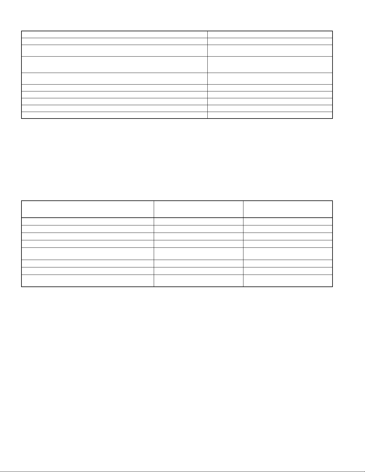
THERMOSTATS AND ACCESSORIES
Thermostat—Auto Changeover, Non-Programmable, °F/°C, 2-Stage Heat, 1-Stage Cool TSTATBBNHP01-B
Thermostat—Auto Changeover, 7-Day Programmable, °F/°C, 2-Stage Heat, 1-Stage Cool TSTATBBPHP01-B
Thermostat—Auto Changeover, 7-Day Programmable, °F/°C, Dual Fuel, Includes Outdoor
Sensor (TSTATXXSEN01) TSTATBBPDF01-B*
Thermidistat™ Control—Non-Programmable/Programmable Thermostat with Humidity
Control (For use in Dual Fuel, AC, HP, and 2S applications. Includes Outdoor Air
Temperature Sensor.) TSTATBBPRH01-B*
Builder’s Thermostat—Manual Changeover, Non-Programmable, °F/°C, 2-Stage Heat,
1-Stage Cool, Heat Pump TSTATBBBHP01*
Outdoor Air Temperature Sensor TSTATXXSEN01
Backplate for Non-Programmable Thermostat TSTATXXNBP01†
Backplate for Programmable Thermostat and Thermidistat™ Control TSTATXXPBP01†
Backplate for Builder’s Thermostat TSTATXXBBP01†
Thermostat Conversion Kit (4 to 5 Wire)—10 Pack TSTATXXCNV10‡
* Do not use in zoning heat pump applications.
† This plate is designed to cover surrounding wall area located behind thermostat.
‡ Thermostat conversion kit is a 24-vac accessory that can turn a 4-wire thermostat application into a 5-wire application. This kit can also be used
to replace a broken thermostat wire, or add an extra wire when needed.
** Outdoor air temperature sensor is an accessory for all Bryant electronic thermostats, except the non-programmable air conditioner version and
builder’s thermostats. It allows the temperature at a remote location (outdoors) to be displayed on the thermostat.
The outdoor air temperature sensor
The outdoor air temperature sensor is included with the Thermidistat Control and dual fuel thermostat.
must be
used with the dual fuel thermostat.
ACCESSORY USAGE GUIDELINE
REQUIRED FOR LOW-AMBIENT
ACCESSORY
Crankcase Heater Yes Yes
Evaporator Freeze Thermostat Yes No
Compressor Start Assist—Capacitor and Relay Yes Yes
Puron Low-Ambient Pressure Switch Yes No
Wind Baffle
Support Feet Recommended No
Puron Hard Shutoff TXV Yes† Yes†
Puron Liquid-Line Solenoid Valve for Heating No
APPLICATIONS
(Below 55°F)
See Low-Ambient
Pressure Switch Instructions
* For tubing line sets between 50 and 175 ft and/or 20 ft elevation difference between indoor and outdoor units, refer to the Application Guideline
and Service Manual for Residential Split-System Air Conditioners and Heat Pumps using Puron Refrigerant.
† Required for all applications.
REQUIRED FOR LONG-LINE
APPLICATIONS*
(Over 50 Ft)
No
See Long-Line
Application Guideline
—6—
Page 7

1.
ACCESSORY DESCRIPTION AND USAGE (Listed Alphabetically)
Compressor Start Assist—Capacitor and Relay
Start capacitor and start relay which gives a “hard” boost to compressor motor at each start-up.
SUGGESTED USE: Installations where interconnecting tube length exceeds 50 ft.
2.
Compressor Start Assist—PTC Type
Solid-state electrical device which gives a “soft” boost to the compressor at each start-up.
SUGGESTED USE: Installations with marginal power supply.
3.
Crankcase Heater
An electric resistance heater which mounts to the base of the compressor to keep the lubricant warm during off cycles. Improves compressor lubrication
on restart and minimizes chance of refrigerant slugging. May or may not include a thermostat control.
SUGGESTED USE: When interconnecting tube length exceeds 50 ft.
4.
Evaporator Freeze Thermostat
An SPST temperature actuated switch which stops unit operation when evaporator reaches freeze-up conditions.
SUGGESTED USE: All units to which Low-Ambient Pressure Switch has been added.
5.
Filter Drier—Suction Line
A device for removing contaminants from refrigerant circulating in a heat pump system; 2-direction flow for heat pumps.
SUGGESTED USE: Split-system heat pumps.
6.
Interface Control (Energy Minder)
An electric control for controlling a heat pump and gas or oil furnace system for maximum energy savings. It allows heat pump to operate down to a
predetermined economic balance point temperature, then switches to allow furnace operation only below that temperature. Requires outdoor thermostat
(Item 11) to be adjusted for economic balance point temperature.
SUGGESTED USE: For heat pump and gas- or oil-fired furnace combination systems unless Duel Fuel Thermostat or Thermidistat™ Control is used.
7.
Isolation Relay
An SPDT relay which switches the Low-Ambient Controller out of the outdoor fan motor circuit when the heat pump switches to heating mode.
SUGGESTED USE: All heat pumps where Low-Ambient Pressure Switch has been added.
8.
Liquid-Line Solenoid Valve (LSV)
An electrically operated shutoff valve to be installed at the outdoor unit which stops and starts refrigerant liquid flow in response to compressor operation.
Maintains a column of refrigerant liquid ready for action at next compressor operation cycle.
SUGGESTED USE: In long-line applications. (Refer to the Residential Split-System Long-Line Application Guideline and Service Manual.)
9.
Low-Ambient Pressure Switch
A long life pressure switch which is mounted to outdoor unit service valve. It is designed to cycle the outdoor fan motor in order to maintain head pressure
within normal operating limits (approximately 200 psig to 365 psig). The control will maintain working head pressure at low-ambient temperatures down to
0°F (–17.8°C) when properly installed.
SUGGESTED USE: Cooling operation at outdoor temperatures below 55°F (12.8°C).
10.
Outdoor Air Temperature Sensor
A device that allows the temperature at a remote location (outdoors) to be displayed at the thermostat.
SUGGESTED USE: All Bryant programmable thermostats.
11.
Outdoor Thermostat
An SPDT temperature actuated switch which turns on supplemental electric heaters when outdoor air temperature drops below set point.
SUGGESTED USE: Heat pump installations with multiple-stage supplemental heaters.
12.
Secondary Outdoor Thermostat
An SPDT temperature actuated switch which turns on a third stage of supplemental electric heaters when outdoor air temperature drops below the
second-stage set point.
SUGGESTED USE: Heat pump installations where 3-stage operation of supplemental heaters is desired.
13.
Service Alarm
A current-sensing lockout relay which provides immediate notification that compressor is not operating during a call for heating or cooling. Used with
proper room thermostat, a thermostat signal is turned on signifying service is required. This can minimize electrical cost increase due to operation of
supplemental heaters only.
SUGGESTED USE: As a feature to notify owner immediately when the system is not operating most efficiently.
14.
Snow Stand
Coated wire rack which supports unit 18 in. above mounting pad to allow for drainage from unit base.
SUGGESTED USE: Heat pump installations in heavy snowfall areas.
15.
Support Feet
Four stick-on plastic feet which raise the unit 4 in. above the mounting pad. This allows sand, dirt, and other debris to be flushed from the unit base;
minimizes corrosion.
SUGGESTED USE: Coastal installations.
16.
Thermostatic Expansion Valve (TXV)—Bi-Flow
A modulating flow-control valve which meters refrigerant liquid flow rate into the evaporator in response to the superheat of the refrigerant gas leaving the
evaporator. Kit includes valve, adapter tubes, and external equalizer tube.
SUGGESTED USE: Required for all installations.
17.
Time-Delay Relay
An SPST delay relay which briefly continues operation of the indoor blower motor to provide additional cooling after the compressor cycles off.
SUGGESTED USE: For improved efficiency ratings for certain combinations of indoor and outdoor units. (Refer to ARI Unitary Directory.)
Installations where outdoor design temperature exceeds 105°F (40.6°C).
Units installed with Low Ambient Pressure Switch. Units installed with Liquid-Line Solenoid Valve.
When unit will be operated below 55°F (12.8°C) outdoor air temperature. (Use with Low-Ambient Pressure Switch.)
All commercial installations.
Heat pump installations in snowdrift locations.
Heat pump installations in areas of prolonged subfreezing temperatures.
All commercial installations.
Windy areas or where debris is normally circulating.
Rooftop installations.
Required for use on all zoning systems.
—7—
Page 8

UNIT
SIZE-
SERIES
FX4ANF030† 800 25,000 TDR&TXV 13.00 — — 11.10 25,000 3.30 16,600 2.38 8.00
F(A,B)4AN(F ,C)030 800 23,600 TDR — 12.50 — 10.95 24,400 3.18 16,500 2.32 7.50
FC4BNF030 800 24,000 TDR — 12.50 — 10.95 24,400 3.18 16,500 2.32 7.50
FK4CNF001 700 24,400 TDR — 13.80 — 12.00 23,800 3.30 16,000 2.42 7.75
FK4CNF002 700 25,200 TDR — 14.00 — 12.35 25,000 3.58 16,100 2.54 8.00
FK4CNF003 700 25,200 TDR — 14.20 — 12.60 25,200 3.54 16,000 2.54 8.00
024-A,C
030-A,C
036-A,C
042-A,C
048-A,C
See notes on page 9.
FV4ANF002 700 25,200 TDR&TXV 14.20 — — 12.05 25,200 3.44 16,100 2.48 8.00
FV4ANF003 700 25,200 TDR&TXV 14.50 — — 12.35 25,000 3.44 15,900 2.48 8.00
CC5A/CD5AA036 900 24,000 NONE — — 13.00 11.10 24,800 3.28 16,600 2.36 7.50
CD5AW036 900 24,000 NONE — — 13.00 11.10 24,800 3.28 16,600 2.36 7.50
CE3AA036 800 23,800 NONE — — 12.60 11.05 24,600 3.20 16,600 2.34 7.40
CJ5A/CK5A/CK5BA036 800 24,200 NONE — — 13.00 11.20 24,800 3.34 16,600 2.38 7.50
CJ5A/CK5A/CK5BW036 800 24,200 NONE — — 13.00 11.20 24,800 3.34 16,600 2.38 7.50
CJ5A/CK5A/CK5BN036 800 24,200 NONE — — 13.00 11.20 24,800 3.34 16,600 2.38 7.50
CK3BA036 800 24,200 NONE — — 13.00 11.20 24,800 3.34 16,600 2.38 7.50
FX4ANF030† 1050 29,000 TDR&TXV 13.00 — — 11.15 30,000 3.56 18,500 2.38 8.00
F(A,B)4AN(F ,C)036 1050 28,400 TDR — 12.20 — 10.75 29,800 3.42 18,700 2.32 7.40
FC4BNF036 1050 28,400 TDR — 12.20 — 10.75 29,800 3.42 18,700 2.32 7.40
FK4CNF001 875 28,600 TDR — 13.70 — 12.10 28,600 3.54 17,800 2.44 7.80
FK4CNF002 875 28,800 TDR — 13.70 — 12.15 29,000 3.68 17,900 2.48 8.00
FK4CNF003 875 29,000 TDR — 14.20 — 12.55 28,600 3.68 17,700 2.50 8.00
FV4ANF002 875 29,200 TDR&TXV 14.00 — — 12.15 29,000 3.68 17,900 2.48 8.10
FV4ANF003 875 29,400 TDR&TXV 14.50 — — 12.55 28,600 3.70 17,700 2.52 8.10
FX4ANF036 1050 29,000 TDR&TXV 12.30 — — 10.85 30,000 3.52 18,800 2.36 8.00
CC5A/CD5AA036 1080 28,800 NONE — — 13.00 11.25 29,400 3.52 18,500 2.38 7.65
CD5AW036 1080 28,800 NONE — — 13.00 11.25 29,400 3.52 18,500 2.38 7.65
CE3AA036 1050 28,600 NONE — — 12.70 11.15 29,200 3.44 18,500 2.36 7.45
CJ5A/CK5A/CK5BN036 1000 28,800 NONE — — 12.70 11.25 29,400 3.54 18,500 2.38 7.65
CJ5A/CK5A/CK5BW036 1050 28,800 NONE — — 13.00 11.30 29,400 3.56 18,500 2.40 7.70
CK3BA036 1050 28,800 NONE — — 13.00 11.30 29,400 3.56 18,500 2.40 7.70
FX4ANF042† 1125 35,000 TDR&TXV 13.00 — — 10.80 35,000 3.40 21,600 2.34 7.70
F(A,B)4AN(F ,B,C)042 1125 33,600 TDR — 12.30 — 10.65 34,200 3.26 21,400 2.28 7.40
FC4BN(F ,B)042 1125 33,600 TDR — 12.30 — 10.65 34,200 3.26 21,400 2.28 7.40
FK4CNF003 1050 34,000 TDR — 13.70 — 11.80 33,600 3.40 20,600 2.40 7.70
FK4CNF005 1050 35,400 TDR — 14.00 — 12.30 33,800 3.70 20,800 2.52 8.00
FV4ANF003 1050 34,400 TDR&TXV 13.70 — — 11.80 33,600 3.44 20,600 2.40 7.80
FV4ANF005 1050 35,600 TDR&TXV 14.00 — — 12.30 34,000 3.70 20,800 2.52 8.10
CC5A/CD5AA042 1125 34,000 NONE — — 12.50 10.65 34,000 3.20 21,400 2.26 7.30
CC5A/CD5AW042 1260 33,600 NONE — — 12.20 10.50 34,000 3.16 21,400 2.24 7.30
CC5A/CD5AC048 1260 33,600 NONE — — 12.20 10.50 33,600 3.10 21,400 2.22 7.30
CC5A/CD5AW048 1275 34,000 NONE — — 12.50 10.60 34,200 3.24 21,400 2.28 7.30
CD5AA048 1275 34,000 NONE — — 12.50 10.65 34,200 3.26 21,400 2.28 7.30
CE3AA042 1125 34,000 NONE — — 12.50 10.65 34,200 3.26 21,600 2.28 7.40
CE3AA048 1125 34,200 NONE — — 12.50 10.70 34,200 3.30 21,600 2.30 7.45
CJ5A/CK5A/CK5BA042 1125 33,800 NONE — — 12.50 10.60 34,200 3.26 21,600 2.28 7.40
CJ5A/CK5A/CK5BN042 1125 33,800 NONE — — 12.50 10.60 34,200 3.26 21,600 2.28 7.40
CJ5A/CK5A/CK5BA048 1125 34,200 NONE — — 12.50 10.70 34,400 3.32 21,600 2.30 7.50
CJ5A/CK5A/CK5BN048 1125 34,200 NONE — — 12.50 10.70 34,400 3.32 21,600 2.30 7.50
CJ5A/CK5A/CK5BW048 1125 34,200 NONE — — 12.50 10.70 34,400 3.32 21,600 2.30 7.50
CK3BA042 1125 33,800 NONE — — 12.50 10.60 34,200 3.26 21,600 2.28 7.40
CK3BA048 1125 34,200 NONE — — 12.50 10.70 34,400 3.32 21,600 2.30 7.50
FV4ANF003† 1225 40,500 TDR&TXV 13.00 — — 11.00 40,500 3.36 25,400 2.46 7.70
F(A,B)4AN(F ,B,C)048 1400 40,000 TDR — 12.00 — 10.25 41,500 3.34 26,600 2.42 7.50
FC4BN(F ,B)048 1400 40,500 TDR — 12.00 — 10.25 41,500 3.38 26,600 2.42 7.55
FK4CNF003 1225 40,500 TDR — 13.00 — 11.10 40,000 3.32 25,400 2.44 7.40
FK4CNF005 1225 41,000 TDR — 13.50 — 11.55 40,000 3.56 25,200 2.56 8.00
FV4ANF005 1225 41,000 TDR&TXV 14.00 — — 11.55 40,000 3.56 25,200 2.56 8.10
FX4ANF042 1400 40,500 TDR&TXV 12.00 — — 10.25 41,500 3.40 26,600 2.42 7.55
CE3AA048 1400 40,500 NONE — — 12.00 10.35 41,500 3.32 26,400 2.40 7.40
CJ5A/CK5A/CK5BA048 1400 40,000 NONE — — 12.00 10.30 41,500 3.34 26,400 2.40 7.50
CJ5A/CK5A/CK5BN048 1400 40,000 NONE — — 12.00 10.30 41,500 3.34 26,400 2.40 7.50
CJ5A/CK5A/CK5BW048 1400 40,000 NONE — — 12.00 10.30 41,500 3.34 26,400 2.40 7.50
CK3BA048 1400 4,0000 NONE — — 12.00 10.30 41,500 3.34 26,400 2.40 7.50
FV4ANF005† 1400 45,500 TDR&TXV 13.50 — — 11.60 47,500 3.58 27,600 2.46 8.50
F(A,B)4AN(F ,B,C)060 1400 44,500 TDR — 11.70 — 10.20 48,500 3.32 29,000 2.26 7.80
FB4ANB070 1400 46,000 TDR — 12.50 — 10.90 48,000 3.54 28,600 2.38 8.00
FC4BN(F ,B)060 1400 44,500 TDR — 11.70 — 10.20 48,000 3.32 29,000 2.26 7.70
FC4BNB070 1400 46,000 TDR — 12.50 — 10.90 48,000 3.54 28,600 2.38 8.00
FK4CNF005 1400 45,500 TDR — 13.20 — 11.60 48,000 3.58 27,800 2.46 8.20
FK4CNB006 1400 46,500 TDR — 14.00 — 12.05 48,000 3.76 27,600 2.54 8.50
FV4ANB006 1400 46,500 TDR&TXV 14.10 — — 12.05 48,000 3.76 27,600 2.54 8.60
FX4ANF048 1400 45,000 TDR&TXV 12.50 — — 10.75 48,000 3.42 28,400 2.34 8.00
FX4ANB060 1400 45,500 TDR&TXV 12.60 — — 10.90 48,000 3.54 28,600 2.38 8.10
CE3AA060 1400 45,500 NONE — — 12.50 10.80 48,000 3.40 28,400 2.34 8.00
INDOOR
UNIT CFM††
COMBINATION RATINGS*
Cooling Heating
Seasonal Efficiency SEER
Field-Supplied
Accessory‡
Puron
TXV
TC
FactorySupplied
Enhance-
ment
Standard
Rating
ARI STANDARD RATINGS*
High-Temp Low-Temp
Puron TXV
& TDR** TC COP TC COP
EER
HSPF
—8—
Page 9

TC
COMBINATION RATINGS Continued
ARI STANDARD RATINGS*
Cooling Heating
Seasonal Efficiency SEER
Factory-
TC
Supplied
Enhance-
ment
Standard
Rating
UNIT
SIZE-
SERIES
048-A,C
060-B,C
* Ratings are net values reflecting the effects of circulating fan heat. Supplemental electric heat is not included. Ratings are based on:
Cooling Standard: 80°F (27°C) db 67°F (19°C) wb indoor entering air temperature and 95°F (35°C) db air entering outdoor unit.
High-Temp Heating Standard: 70°F (21°C) db indoor entering air temperature and 47°F (8°C) db 43°F (6°C) wb air entering outdoor unit.
Low-Temp Heating Standard: 70°F (21°C) db indoor entering air temperature and 17°F (–9°C) db 15°F (–10°C) wb air entering outdoor unit.
† Outdoor section/indoor section combination tested in accordance with DOE test procedure for heat pumps.
‡ Based on computer simulation. TXV must be Puron compatible and hard shutoff type.
** In most cases, only 1 method should be used to achieve TDR function. Using more than 1 method in a system may cause degradation in performance.
Use either the accessory Time-Delay Relay KAATD0101TDR or a furnace equipped with TDR. All Bryant furnaces are equipped with TDR except for the
394HAD.
†† Indoor Airflow
COP — Coefficient of Performance
EER — Energy Efficiency Ratio
HSPF — Heating Seasonal Performance Factor
SEER — Seasonal Energy Efficiency Ratio
— Total Capacity (Btuh)
TDR — Time-Delay Relay
TXV — Thermostatic Expansion Valve
INDOOR
UNIT CFM††
CJ5A/CK5A/CK5BA060 1400 45,000 NONE — — 12.50 10.75 48,000 3.50 28,600 2.38 8.20
CJ5A/CK5A/CK5BN060 1400 45,500 NONE — — 13.00 10.90 48,500 3.52 28,600 2.38 8.25
CJ5A/CK5A/CK5BX060 1400 45,500 NONE — — 13.00 10.90 48,500 3.52 28,600 2.38 8.25
CK3BA060 1400 45,000 NONE — — 12.50 10.75 48,000 3.50 28,600 2.38 8.20
FV4ANB006† 1750 58,000 TDR&TXV 13.00 — — 10.75 60,000 3.56 37,000 2.54 8.00
FB4ANB070 1750 57,000 TDR — 12.00 — 10.20 60,000 3.44 37,800 2.46 7.80
FC4BNB070 1750 57,000 TDR — 12.00 — 10.20 60,000 3.44 37,800 2.46 7.80
FK4CNB006 1750 58,000 TDR — 12.80 — 10.75 59,500 3.56 37,000 2.54 8.00
FX4ANB060 1750 57,000 TDR&TXV 12.00 — — 10.20 60,000 3.44 37,800 2.46 7.80
CC5A/CD5AW060 1750 56,000 NONE — — 12.50 10.45 58,500 3.26 36,800 2.42 7.50
CJ5A/CK5A/CK5BX060 1750 56,500 NONE — — 12.50 10.55 59,000 3.44 37,000 2.50 7.70
Field-Supplied
Accessory‡
Puron
Puron TXV
TXV
& TDR** TC COP TC COP
EER
High-Temp Low-Temp
HSPF
—9—
Page 10

NOTE:
cycles depends on the outdoor/indoor combination, indoor airflow, installation practices, and system maintenance, all of which affect
system performance.
BUILDING HEAT LOSS, 1000 BTU/HR
The performance shown includes the PressureGuard™ cycling the outdoor fan. The ambient temperature that the outdoor fan
UNIT INTEGRATED HEATING CAPACITY, 1000 BTU/HR
10
20
30
40
50
60
70
80
650A BALANCE POINT WORKSHEET
OUTDOOR TEMPERA TURE, ˚F
A99002
80706050403020100-10
BASED ON INDOOR ENT. AIR AT
70˚F AND AT RATED CFM
2.9
5.9
FX4A030
650AN024-A,C
FX4A030
8.8
650AN030-A,C
FX4A042
11.7
KW
650AN042-A,C
FV4A003
650AN036-A,C
14.7
FV4A006
650AN048-A,C
FV4A005
17.6
650AN060-B,C
20.5
23.4
—10—
Page 11

DETAILED COOLING CAPACITIES*
EVAP
AIR
CFM EWB
75 85 95 105 115 125
Capacity
MBtuh†
Total
Sys
Kw**
Capacity
MBtuh†
650AN024-A,C Outdoor Section With FX4ANF030 Indoor Section
72 29.7 14.5 1.85 28.4 14.0 2.07 26.9 13.5 2.31 25.4 12.9 2.57 23.8 12.3 2.85 22.0 11.7 3.14
67 27.2 18.2 1.85 25.9 17.6 2.06 24.6 17.1 2.30 23.2 16.5 2.55 21.7 15.9 2.83 20.1 15.3 3.12
700
63†† 25.3 17.7 1.85 24.1 17.2 2.06 22.9 16.6 2.29 21.6 16.1 2.54 20.2 15.5 2.82 18.7 14.8 3.11
62 24.8 21.7 1.84 23.7 21.2 2.06 22.5 20.6 2.29 21.3 20.0 2.54 20.0 19.4 2.81 18.6 18.5 3.11
57 23.7 23.7 1.84 22.8 22.8 2.06 21.9 21.9 2.29 20.9 20.9 2.54 19.8 19.8 2.81 18.6 18.6 3.11
72 30.3 15.2 1.88 28.9 14.6 2.11 27.3 14.1 2.35 25.8 13.6 2.61 24.1 13.0 2.88 22.2 12.3 3.18
67 27.7 19.3 1.88 26.4 18.7 2.10 25.0 18.2 2.34 23.6 17.6 2.59 22.0 17.0 2.87 20.4 16.4 3.16
800
63†† 25.8 18.8 1.88 24.6 18.2 2.10 23.3 17.7 2.33 21.9 17.1 2.58 20.5 16.5 2.85 19.0 15.8 3.15
62 25.4 23.3 1.88 24.2 22.7 2.10 23.0 22.1 2.33 21.8 21.4 2.58 20.5 20.5 2.85 19.2 19.2 3.15
57 24.7 24.7 1.88 23.7 23.7 2.10 22.7 22.7 2.33 21.6 21.6 2.58 20.5 20.5 2.85 19.2 19.2 3.15
72 30.8 15.8 1.92 29.3 15.3 2.14 27.7 14.7 2.38 26.1 14.2 2.64 24.3 13.6 2.92 22.4 12.9 3.22
67 28.2 20.4 1.92 26.8 19.8 2.14 25.3 19.3 2.37 23.9 18.7 2.63 22.3 18.1 2.90 20.5 17.4 3.20
900
63†† 26.2 19.8 1.92 24.9 19.2 2.13 23.6 18.6 2.37 22.2 18.1 2.62 20.8 17.4 2.89 19.1 16.7 3.19
62 25.9 24.7 1.92 24.7 24.1 2.13 23.5 23.3 2.37 22.3 22.3 2.62 21.1 21.1 2.89 19.7 19.7 3.19
57 25.5 25.5 1.91 24.5 24.5 2.13 23.4 23.4 2.37 22.3 22.3 2.62 21.1 21.1 2.89 19.7 19.7 3.19
Multipliers for Determining the Performance With Other Indoor Sections
Indoor
Section Size
FX4ANF 030 1.00 1.00 CE3AA 030 0.94 1.00
F(A,B)4AN(F,C) 030 0.94 1.00 036 0.95 1.00
FC4BNF 030 0.96 1.00 CJ5A/CK5A/CK5BA 030 0.94 1.00
FK4CNF 001 0.98 0.93 036 0.97 1.00
002 1.01 0.93 CJ5A/CK5A/CK5BN 036 0.97 1.00
003 1.01 0.91 CJ5A/CK5A/CK5BW 030 0.94 1.00
FV4ANF 002 1.01 0.93 036 0.97 1.00
003 1.01 0.91 CK3BA 030 0.94 1.00
— — — 036 0.97 1.00
See notes on page 14.
Capacity Power Capacity Power
CONDENSER ENTERING AIR TEMPERATURES °F
Capacity
Sys
MBtuh†
Indoor
Section Size
,
Cooling
Total
Sys
Kw**
Capacity
MBtuh†
Total
Kw**
Total
Sys
Kw**
Capacity
MBtuh†
Total
Sys
Kw**
Capacity
MBtuh†
Cooling
Total
Sys
Kw**Total Sens‡ Total Sens‡ Total Sens‡ Total Sens‡ Total Sens‡ Total Sens‡
—11—
Page 12

DETAILED COOLING CAPACITIES* Continued
EVAP
AIR
CFM EWB
75 85 95 105 115 125
Capacity
MBtuh†
Total
Sys
Kw**
Capacity
MBtuh†
CONDENSER ENTERING AIR TEMPERATURES °F
Total
Sys
Kw**
Capacity
MBtuh†
Total
Kw**
Sys
Capacity
MBtuh†
Total
Sys
Kw**
Capacity
MBtuh†
Total
Sys
Kw**
Capacity
MBtuh†
650AN030-A,C Outdoor Section With FX4ANF030 Indoor Section
72 34.3 17.2 2.07 32.6 16.6 2.31 30.9 15.9 2.58 29.0 15.3 2.87 27.0 14.6 3.20 24.8 13.8 3.56
67 31.4 21.7 2.06 29.9 21.1 2.29 28.3 20.5 2.56 26.6 19.8 2.86 24.8 19.1 3.18 22.7 18.3 3.54
1825
63†† 29.2 21.1 2.04 27.8 20.5 2.28 26.4 19.9 2.55 24.8 19.2 2.84 23.1 18.5 3.17 21.2 17.7 3.53
62 28.8 26.2 2.04 27.4 25.5 2.28 26.0 24.8 2.55 24.5 24.0 2.84 23.0 23.0 3.17 21.4 21.4 3.53
57 27.8 27.8 2.04 26.7 26.7 2.27 25.6 25.6 2.54 24.3 24.3 2.84 23.0 23.0 3.17 21.4 21.4 3.53
72 35.2 18.7 2.14 33.5 18.1 2.38 31.6 17.4 2.65 29.7 16.8 2.94 27.6 16.1 3.27 25.2 15.3 3.62
67 32.4 24.3 2.13 30.7 23.7 2.36 29.0 23.0 2.63 27.2 22.3 2.93 25.3 21.6 3.25 23.2 20.7 3.61
1050
63†† 30.2 23.6 2.11 28.6 22.9 2.35 27.0 22.3 2.62 25.4 21.5 2.91 23.6 20.8 3.24 21.6 19.9 3.59
62 29.9 29.4 2.11 28.6 28.5 2.35 27.2 27.2 2.62 25.8 25.8 2.91 24.3 24.3 3.24 22.5 22.5 3.60
57 29.8 29.8 2.11 28.5 28.5 2.35 27.2 27.2 2.62 25.8 25.8 2.91 24.3 24.3 3.24 22.6 22.6 3.60
72 35.8 20.0 2.20 34.0 19.4 2.44 32.1 18.7 2.71 30.0 18.1 3.00 27.8 17.3 3.33 25.4 16.5 3.68
67 32.9 26.5 2.19 31.2 25.8 2.42 29.4 25.1 2.69 27.6 24.4 2.98 25.6 23.6 3.31 23.4 22.6 3.67
1250
63†† 30.7 25.6 2.17 29.1 24.9 2.41 27.5 24.2 2.67 25.7 23.4 2.97 23.9 22.6 3.30 21.9 21.5 3.65
62 31.0 31.0 2.17 29.7 29.7 2.41 28.3 28.3 2.68 26.8 26.8 2.98 25.1 25.1 3.31 23.2 23.2 3.67
57 31.0 31.0 2.17 29.7 29.7 2.41 28.3 28.3 2.68 26.8 26.8 2.98 25.1 25.1 3.31 23.2 23.2 3.67
Multipliers for Determining the Performance With Other Indoor Sections
Indoor
Section Size
FX4ANF 030 1.00 1.00 FV4ANF 002 1.01 0.93
F(A,B)4AN(F,C) 030 0.97 1.00 003 1.01 0.90
036 0.98 1.03 FX4ANF 036 1.00 1.03
FC4BNF 030 0.97 1.00 CE3AA 036 0.99 1.00
036 0.98 1.03 CJ5A/CK5A/CK5BN 036 0.99 1.00
FK4CNF 001 0.99 0.92 CJ5A/CK5A/CK5BW 036 0.99 1.00
002 0.99 0.93 CK3BA 036 0.99 1.00
003 1.00 0.90 — — —
Capacity Power Capacity Power
Cooling
Indoor
Section Size
Cooling
650AN036-A,C Outdoor Section With FX4ANF042 Indoor Section
72 42.3 21.3 2.64 40.3 20.6 2.93 38.3 19.8 3.26 36.0 19.1 3.61 33.7 18.3 4.00 31.0 17.4 4.40
67 38.7 27.3 2.63 36.9 26.5 2.93 35.0 25.8 3.25 33.0 25.0 3.60 30.8 24.1 3.98 28.3 23.2 4.38
1125
63†† 36.1 26.5 2.63 34.4 25.7 2.92 32.6 25.0 3.24 30.6 24.1 3.59 28.6 23.3 3.96 26.3 22.3 4.36
62 35.5 33.0 2.63 33.9 32.2 2.92 32.2 31.4 3.24 30.4 30.3 3.59 28.7 28.7 3.96 26.8 26.8 4.37
57 34.7 34.7 2.63 33.3 33.3 2.92 31.9 31.9 3.24 30.4 30.4 3.59 28.7 28.7 3.96 26.8 26.8 4.37
72 42.7 22.1 2.69 40.7 21.4 2.98 38.6 20.6 3.31 36.3 19.9 3.66 33.9 19.0 4.05 31.2 18.1 4.46
67 39.2 28.6 2.68 37.3 27.9 2.98 35.4 27.1 3.30 33.2 26.3 3.65 31.0 25.4 4.03 28.5 24.5 4.43
1250
63†† 36.6 27.8 2.68 34.8 27.0 2.97 32.9 26.2 3.29 31.0 25.4 3.64 28.8 24.5 4.01 26.5 23.5 4.41
62 36.1 34.8 2.68 34.5 33.9 2.97 32.8 32.8 3.29 31.2 31.2 3.64 29.4 29.4 4.02 27.4 27.4 4.42
57 35.7 35.7 2.68 34.3 34.3 2.97 32.8 32.8 3.29 31.2 31.2 3.64 29.4 29.4 4.02 27.4 27.4 4.42
72 43.1 22.8 2.74 41.1 22.1 3.03 38.9 21.4 3.36 36.6 20.6 3.71 34.1 19.8 4.10 31.3 18.9 4.51
67 39.6 30.0 2.73 37.7 29.2 3.03 35.6 28.4 3.35 33.5 27.6 3.70 31.3 26.7 4.08 28.7 25.7 4.48
1375
63†† 36.9 29.0 2.73 35.1 28.2 3.02 33.2 27.4 3.34 31.2 26.6 3.69 29.0 25.7 4.06 26.7 24.6 4.46
62 36.7 36.4 2.73 35.1 35.1 3.02 33.5 33.5 3.34 31.8 31.8 3.69 30.0 30.0 4.07 28.0 28.0 4.48
57 36.6 36.6 2.73 35.1 35.1 3.02 33.5 33.5 3.34 31.8 31.8 3.69 30.0 30.0 4.07 27.9 27.9 4.48
Multipliers for Determining the Performance With Other Indoor Sections
Indoor
Section Size
FX4ANF 042 1.00 1.00 CE3AA 042 0.97 1.00
F(A,B)4AN(F,B,C) 042 0.96 1.00 048 0.98 1.00
FC4BN(F,B) 042 0.96 1.00 CJ5A/CK5A/CK5BA 042 0.97 1.00
FK4CNF 003 0.97 0.91 048 0.98 1.00
005 1.01 0.91 CJ5A/CK5A/CK5BN 042 0.97 1.00
FV4ANF 003 0.98 0.91 048 0.98 1.00
005 1.02 0.91 CJ5A/CK5A/CK5BW 048 0.98 1.00
CC5A/CD5AA 042 0.99 1.00 CK3BA 042 0.97 1.00
— — — 048 0.98 1.00
See notes on page 14.
Capacity Power Capacity Power
Cooling
Indoor
Section Size
Cooling
Total
Sys
Kw**Total Sens‡ Total Sens‡ Total Sens‡ Total Sens‡ Total Sens‡ Total Sens‡
—12—
Page 13

DETAILED COOLING CAPACITIES* Continued
EVAP
AIR
CFM EWB
75 85 95 105 115 125
Capacity
MBtuh†
Total
Sys
Kw**
Capacity
MBtuh†
CONDENSER ENTERING AIR TEMPERATURES °F
Total
Sys
Kw**
Capacity
MBtuh†
Total
Kw**
Sys
Capacity
MBtuh†
Total
Sys
Kw**
Capacity
MBtuh†
Total
Sys
Kw**
Capacity
MBtuh†
650AN042-A,C Outdoor Section With FV4ANF003 Indoor Section
72 48.5 24.4 2.95 46.4 23.6 3.32 44.1 22.8 3.72 41.7 21.9 4.17 39.0 21.0 4.65 36.1 20.0 5.17
67 44.6 30.9 2.91 42.6 30.1 3.28 40.5 29.2 3.68 38.3 28.3 4.12 35.8 27.4 4.61 33.2 26.3 5.12
1225
63†† 41.7 30.1 2.89 39.8 29.3 3.25 37.8 28.4 3.65 35.7 27.5 4.09 33.4 26.5 4.57 31.0 25.5 5.09
62 41.0 37.2 2.88 39.2 36.3 3.24 37.3 35.3 3.65 35.3 34.3 4.09 33.2 33.0 4.57 31.1 31.1 5.09
57 39.7 39.7 2.87 38.2 38.2 3.24 36.7 36.7 3.64 35.0 35.0 4.08 33.1 33.1 4.57 31.1 31.1 5.09
72 49.4 25.6 2.99 47.1 24.8 3.36 44.8 23.9 3.77 42.2 23.1 4.22 39.5 22.1 4.70 36.5 21.1 5.22
67 45.4 32.9 2.96 43.3 32.0 3.32 41.2 31.2 3.73 38.8 30.2 4.17 36.3 29.3 4.65 33.6 28.2 5.17
1400
63†† 42.5 32.0 2.93 40.5 31.1 3.30 38.4 30.2 3.70 36.2 29.3 4.14 33.9 28.3 4.62 31.3 27.2 5.14
62 41.9 39.7 2.93 40.0 38.7 3.29 38.2 37.6 3.70 36.2 36.2 4.14 34.2 34.2 4.62 32.0 32.0 5.15
57 41.2 41.2 2.92 39.6 39.6 3.29 37.9 37.9 3.69 36.1 36.1 4.14 34.2 34.2 4.62 32.0 32.0 5.15
72 50.0 26.7 3.04 47.7 25.9 3.41 45.3 25.1 3.81 42.7 24.2 4.26 39.9 23.2 4.74 36.8 22.2 5.26
67 46.0 34.7 3.00 43.9 33.9 3.37 41.6 33.0 3.77 39.3 32.1 4.22 36.7 31.1 4.70 33.9 29.9 5.22
1575
63†† 43.1 33.7 2.98 41.0 32.8 3.34 38.9 31.9 3.74 36.7 31.0 4.19 34.3 29.9 4.66 31.6 28.8 5.18
62 42.7 41.9 2.97 40.9 40.7 3.34 39.0 39.0 3.74 37.1 37.1 4.19 35.1 35.1 4.68 32.8 32.8 5.20
57 42.4 42.4 2.97 40.8 40.8 3.34 39.0 39.0 3.74 37.1 37.1 4.19 35.1 35.1 4.68 32.8 32.8 5.20
Multipliers for Determining the Performance With Other Indoor Sections
Indoor
Section Size
FV4ANF 003 1.00 1.00 CE3AA 048 1.00 1.08
F(A,B)4AN(F,B,C) 048 0.99 1.07 CJ5A/CK5A/CK5BA 048 0.99 1.08
FC4BN(F,B) 048 1.00 1.09 CJ5A/CK5A/CK5BN 048 0.99 1.08
FK4CNF 003 1.00 1.00 CJ5A/CK5A/CK5BW 048 0.99 1.08
005 1.01 0.98 CK3BA 048 0.99 1.08
FV4ANF 005 1.01 0.98 — — —
FX4ANF 042 1.00 1.09
Capacity Power Capacity Power
Cooling
Indoor
Section Size
Cooling
650AN048-A,C Outdoor Section With FV4ANF005 Indoor Section
72 54.7 27.7 3.20 52.2 26.8 3.56 49.6 25.9 3.96 46.9 24.9 4.41 43.9 23.9 4.90 40.7 22.8 5.43
67 50.2 35.2 3.16 47.9 34.3 3.52 45.5 33.3 3.92 43.0 32.3 4.36 40.3 31.3 4.85 37.4 30.1 5.39
1400
63†† 46.8 34.3 3.13 44.7 33.3 3.49 42.4 32.4 3.89 40.1 31.3 4.33 37.6 30.3 4.82 34.9 29.1 5.36
62 46.1 42.5 3.12 44.0 41.5 3.48 42.0 40.5 3.88 39.7 39.3 4.33 37.5 37.5 4.82 35.2 35.2 5.37
57 44.9 44.9 3.11 43.2 43.2 3.47 41.4 41.4 3.88 39.6 39.6 4.33 37.5 37.5 4.82 35.2 35.2 5.37
72 55.6 29.1 3.26 53.0 28.1 3.62 50.3 27.2 4.02 47.4 26.2 4.47 44.4 25.2 4.96 41.1 24.1 5.49
67 51.1 37.5 3.22 48.7 36.6 3.58 46.2 35.6 3.98 43.6 34.6 4.42 40.8 33.5 4.91 37.8 32.3 5.45
1600
63†† 47.7 36.5 3.19 45.4 35.5 3.55 43.1 34.5 3.95 40.7 33.5 4.39 38.1 32.4 4.88 35.3 31.2 5.42
62 47.1 45.5 3.18 45.1 44.4 3.54 42.9 42.9 3.95 41.0 41.0 4.39 38.8 38.8 4.89 36.3 36.3 5.43
57 46.7 46.7 3.18 44.8 44.8 3.54 42.9 42.9 3.94 40.9 40.9 4.39 38.8 38.8 4.89 36.4 36.4 5.43
72 56.3 30.4 3.32 53.6 29.4 3.68 50.8 28.5 4.08 47.9 27.5 4.53 44.8 26.5 5.01 41.4 25.4 5.55
67 51.7 39.7 3.28 49.3 38.8 3.64 46.7 37.8 4.04 44.1 36.8 4.48 41.2 35.7 4.97 38.2 34.4 5.51
1800
63†† 48.3 38.5 3.24 46.0 37.5 3.60 43.6 36.5 4.00 41.1 35.5 4.45 38.5 34.4 4.94 35.7 33.1 5.48
62 48.2 48.1 3.24 46.2 46.2 3.61 44.2 44.2 4.01 42.1 42.1 4.46 39.8 39.8 4.95 37.3 37.3 5.50
57 48.1 48.1 3.24 46.2 46.2 3.60 44.2 44.2 4.01 42.1 42.1 4.46 39.8 39.8 4.95 37.3 37.3 5.50
Multipliers for Determining the Performance With Other Indoor Sections
Indoor
Section Size
FV4ANF 005 1.00 1.00 FX4ANF 048 0.99 1.06
F(A,B)4AN(F,B,C) 060 0.98 1.10 FX4ANB 060 1.00 1.06
FB4ANB 070 1.01 1.06 CE3AA 060 1.00 1.06
FC4BN(F,B) 060 0.98 1.10 CJ5A/CK5A/CK5BA 060 0.99 1.06
FC4BNB 070 1.01 1.06 CJ5A/CK5A/CK5BN 060 1.00 1.06
FK4CNB 006 1.02 0.98 CJ5A/CK5A/CK5BX 060 1.00 1.06
FK4CNF 005 1.00 1.00 CK3BA 060 0.99 1.06
FV4ANB 006 1.02 0.98 — — —
See notes on page 14.
Capacity Power Capacity Power
Cooling
Indoor
Section Size
Cooling
Total
Sys
Kw**Total Sens‡ Total Sens‡ Total Sens‡ Total Sens‡ Total Sens‡ Total Sens‡
—13—
Page 14

DETAILED COOLING CAPACITIES* Continued
EVAP
AIR
CFM EWB
75 85 95 105 115 125
Capacity
MBtuh†
Total
Sys
Kw**
Capacity
MBtuh†
CONDENSER ENTERING AIR TEMPERATURES °F
Total
Sys
Kw**
Capacity
MBtuh†
Total
Kw**
Sys
Capacity
MBtuh†
Total
Sys
Kw**
Capacity
MBtuh†
Total
Sys
Kw**
Capacity
MBtuh†
650AN060-B,C Outdoor Section With FV4ANB006 Indoor Section
72 70.1 35.6 4.43 66.6 34.4 4.92 63.1 33.1 5.47 59.2 31.7 6.07 55.0 30.3 6.73 50.2 28.7 7.42
67 64.4 45.5 4.35 61.3 44.2 4.85 58.0 42.9 5.40 54.5 41.5 6.00 50.6 40.0 6.65 46.4 38.4 7.35
1750
63†† 60.2 44.3 4.30 57.2 43.0 4.79 54.2 41.7 5.34 50.9 40.3 5.94 47.3 38.8 6.60 43.4 37.1 7.30
62 59.2 55.1 4.29 56.4 53.7 4.78 53.5 52.3 5.33 50.5 50.4 5.93 47.5 47.5 6.60 44.2 44.2 7.32
57 57.8 57.8 4.27 55.6 55.6 4.77 53.1 53.1 5.32 50.5 50.5 5.93 47.5 47.5 6.60 44.2 44.2 7.32
72 71.1 37.4 4.52 67.6 36.1 5.02 63.9 34.8 5.57 59.8 33.4 6.16 55.5 32.0 6.81 50.6 30.4 7.51
67 65.5 48.5 4.44 62.2 47.2 4.94 58.8 45.9 5.49 55.1 44.4 6.09 51.1 42.9 6.74 46.8 41.2 7.44
2000
63†† 61.2 47.1 4.39 58.1 45.8 4.88 54.9 44.4 5.43 51.6 43.0 6.03 47.9 41.5 6.68 43.8 39.7 7.39
62 60.5 59.0 4.38 57.7 57.4 4.88 54.9 54.9 5.43 52.1 52.1 6.04 48.9 48.9 6.70 45.3 45.3 7.42
57 60.1 60.1 4.38 57.6 57.6 4.88 54.9 54.9 5.43 52.1 52.1 6.04 49.0 49.0 6.70 45.4 45.4 7.42
72 72.0 39.1 4.61 68.3 37.8 5.10 64.4 36.5 5.65 60.4 35.1 6.25 55.9 33.7 6.90 50.8 32.0 7.59
67 66.2 51.4 4.53 62.9 50.1 5.03 59.4 48.7 5.57 55.6 47.3 6.17 51.7 45.7 6.83 47.1 43.9 7.53
2250
63†† 61.9 49.8 4.48 58.8 48.5 4.97 55.6 47.1 5.52 52.1 45.6 6.12 48.3 44.0 6.77 44.1 42.1 7.48
62 61.8 61.8 4.48 59.2 59.2 4.98 56.5 56.5 5.53 53.5 53.5 6.14 50.2 50.2 6.80 46.4 46.4 7.51
57 61.8 61.8 4.48 59.2 59.2 4.98 56.4 56.4 5.53 53.4 53.4 6.14 50.2 50.2 6.80 46.4 46.4 7.51
Multipliers for Determining the Performance With Other Indoor Sections
Indoor
Section Size
FV4ANB 006 1.00 1.00 FX4ANB 060 0.98 1.04
FB4ANB 070 0.98 1.04 CC5A/CD5AW 060 0.97 0.99
FC4BNB 070 0.98 1.04 CJ5A/CK5A/CK5BX 060 0.97 1.00
FK4CNB 006 1.00 1.00 — — —
* Detailed cooling capacities are based on indoor and outdoor unit at the same elevation per ARI standard 210/240-94. If additional tubing length and/or
indoor unit is located above outdoor unit, a slight variation in capacity may occur.
† T otal and sensible capacities are net capacities. Blo w er motor heat has been subtracted.
‡ Sensible capacities shown are based on 80°F (27°C) entering air at the indoor coil. For sensible capacities at other than 80°F (27°C), deduct 835 Btuh
(245 kw) per 1000 CFM (480 L/S) of indoor coil air for each degree below 80°F (27°C), or add 835 Btuh (245 kw) per 1000 CFM (480 L/S) of indoor coil air
per degree above 80°F (27°C).
** System kw is total of indoor and outdoor unit kilowatts.
†† At TVA rating indoor condition (75°F edb/63°F ewb). All other indoor air temperatures are at 80°F edb.
EWB—Entering Wet Bulb
Capacity Power Capacity Power
Cooling
Indoor
Section Size
Cooling
Total
Sys
Kw**Total Sens‡ Total Sens‡ Total Sens‡ Total Sens‡ Total Sens‡ Total Sens‡
—14—
Page 15

HEAT PUMP HEATING PERFORMANCE
INDOOR
AIR
EDB CFM
–3 7 172737475767
Capacity
MBtuh†
Total Int* Kw† Total Int* Kw† Total Int* Kw† Total Int* Kw† Total Int* Kw† Total Int* Kw† Total Int* Kw† Total Int* Kw†
Total
Pwr
Capacity
MBtuh†
Total
Pwr
OUTDOOR COIL ENTERING AIR TEMPERATURES °F
Capacity
MBtuh†
Total
Pwr
Capacity
MBtuh†
Total
Pwr
Capacity
MBtuh†
Total
Pwr
Capacity
MBtuh†
Total
Pwr
Capacity
MBtuh†
Total
Pwr
650AN024-A,C Outdoor Section With FX4ANF030 Indoor Section
700 12.0 11.1 1.79 14.3 13.1 1.87 16.6 15.1 1.95 19.0 16.9 2.04 21.9 19.9 2.16 25.0 25.0 2.30 28.5 28.5 2.48 32.6 32.6 2.74
65
800 12.2 11.2 1.80 14.5 13.3 1.87 16.8 15.3 1.95 19.2 17.1 2.03 22.1 20.1 2.13 25.4 25.4 2.27 28.9 28.9 2.44 33.1 33.1 2.69
900 12.4 11.4 1.82 14.6 13.4 1.88 17.0 15.5 1.95 19.4 17.3 2.03 22.4 20.4 2.13 25.6 25.6 2.25 29.3 29.3 2.43 33.4 33.4 2.67
700 11.8 10.8 1.87 14.1 13.0 1.96 16.4 15.0 2.05 18.8 16.7 2.14 21.6 19.6 2.26 24.7 24.7 2.41 28.1 28.1 2.60 32.0 32.0 2.87
70
800 12.0 11.0 1.88 14.3 13.1 1.96 16.6 15.1 2.04 19.0 16.9 2.13 21.8 19.9 2.24 25.0 25.0 2.38 28.5 28.5 2.56 32.5 32.5 2.81
900 12.1 11.2 1.90 14.4 13.3 1.97 16.8 15.3 2.05 19.2 17.0 2.13 22.1 20.1 2.23 25.3 25.3 2.36 28.8 28.8 2.54 32.9 32.9 2.79
700 11.5 10.6 1.96 13.9 12.8 2.05 16.2 14.8 2.15 18.5 16.5 2.25 21.3 19.4 2.38 24.3 24.3 2.53 27.7 27.7 2.73 31.5 31.5 3.00
75
800 11.7 10.7 1.97 14.1 13.0 2.06 16.4 15.0 2.14 18.8 16.7 2.23 21.5 19.6 2.35 24.6 24.6 2.50 28.1 28.1 2.68 32.0 32.0 2.94
900 11.8 10.9 1.98 14.3 13.1 2.07 16.6 15.1 2.15 19.0 16.8 2.23 21.8 19.8 2.34 24.9 24.9 2.48 28.4 28.4 2.66 32.4 32.4 2.91
Multipliers for Determining the Performance With Other Indoor Sections
Indoor
Section Size
FX4ANF 030 1.00 1.00 CE3AA 030 0.98 1.01
F(A,B)4AN(F,C) 030 0.98 1.01 036 0.98 1.01
FC4BNF 030 0.98 1.01 CJ5A/CK5A/CK5BA 030 0.98 1.01
FK4CNF 001 0.95 0.95 036 0.99 0.98
002 1.00 0.92 CJ5A/CK5A/CK5BN 036 0.99 0.98
003 1.01 0.94 CJ5A/CK5A/CK5BW 030 0.98 1.01
FV4ANF 002 1.01 0.97 036 0.99 0.98
003 1.00 0.96 CK3BA 030 0.98 1.01
— — — 036 0.99 0.98
Capacity Power Capacity Power
Cooling
Indoor
Section Size
Cooling
650AN030-A,C Outdoor Section With FX4ANF030 Indoor Section
825 12.6 11.6 2.07 15.4 14.1 2.12 18.3 16.7 2.16 21.6 19.2 2.22 25.4 23.1 2.29 29.7 29.7 2.39 34.6 34.6 2.69 32.7 32.7 2.55
65
1050 12.9 11.9 2.11 15.7 14.4 2.14 18.7 17.0 2.17 22.0 19.6 2.21 25.9 23.6 2.27 30.4 30.4 2.35 35.4 35.4 2.63 33.5 33.5 2.49
1250 13.2 12.2 2.15 16.0 14.7 2.17 19.0 17.3 2.19 22.4 19.9 2.23 26.3 23.9 2.28 30.8 30.8 2.36 36.0 36.0 2.64 33.9 33.9 2.49
825 12.3 11.3 2.18 15.2 14.0 2.23 18.1 16.5 2.28 21.4 19.0 2.33 25.1 22.8 2.41 29.4 29.4 2.52 34.1 34.1 2.82 32.2 32.2 2.67
70
1050 12.7 11.7 2.21 15.6 14.3 2.25 18.5 16.9 2.28 21.8 19.4 2.32 25.6 23.3 2.38 30.0 30.0 2.47 34.9 34.9 2.76 33.0 33.0 2.60
1250 13.0 11.9 2.25 15.8 14.5 2.28 18.8 17.1 2.30 22.1 19.6 2.34 26.0 23.6 2.39 30.4 30.4 2.47 35.4 35.4 2.76 33.4 33.4 2.60
825 12.0 11.1 2.29 15.0 13.7 2.34 18.0 16.4 2.40 21.1 18.8 2.46 24.8 22.6 2.54 29.0 29.0 2.65 33.7 33.7 2.96 31.7 31.7 2.80
75
1050 12.4 11.4 2.32 15.3 14.1 2.35 18.3 16.7 2.40 21.6 19.1 2.44 25.3 23.0 2.50 29.6 29.6 2.59 34.4 34.4 2.89 32.5 32.5 2.72
1250 12.7 11.7 2.36 15.6 14.4 2.39 18.6 17.0 2.42 21.9 19.4 2.45 25.7 23.4 2.51 30.0 30.0 2.59 34.9 34.9 2.89 33.0 33.0 2.71
Multipliers for Determining the Performance With Other Indoor Sections
Indoor
Section Size
FX4ANF 030 1.00 1.00 FV4ANF 002 0.97 0.94
F(A,B)4AN(F,C) 030 0.98 1.02 003 0.95 0.92
036 0.99 1.03 FX4ANF 036 1.00 1.01
FC4BNF 030 0.98 1.02 CE3AA 036 0.97 1.01
036 0.99 1.03 CJ5A/CK5A/CK5BN 036 0.98 0.99
FK4CNF 001 0.95 0.96 CJ5A/CK5A/CK5BW 036 0.98 0.98
002 0.97 0.94 CK3BA 036 0.98 0.98
003 0.95 0.92 — — —
See notes on page 17.
Capacity Power Capacity Power
Cooling
Indoor
Section Size
Cooling
Capacity
MBtuh†
Total
Pwr
—15—
Page 16

HEAT PUMP HEATING PERFORMANCE Continued
INDOOR
AIR
EDB CFM
–3 7 172737475767
Capacity
MBtuh†
Total Int* Kw† Total Int* Kw† Total Int* Kw† Total Int* Kw† Total Int* Kw† Total Int* Kw† Total Int* Kw† Total Int* Kw†
Total
Pwr
Capacity
MBtuh†
Total
Pwr
OUTDOOR COIL ENTERING AIR TEMPERATURES °F
Capacity
MBtuh†
Total
Pwr
Capacity
MBtuh†
Total
Pwr
Capacity
MBtuh†
Total
Pwr
Capacity
MBtuh†
Total
Pwr
Capacity
MBtuh†
Total
Pwr
Capacity
650AN036-A,C Outdoor Section With FX4ANF042 Indoor Section
1125 14.7 13.5 2.42 18.3 16.8 2.51 21.9 20.0 2.59 25.8 22.9 2.66 30.4 27.6 2.76 35.6 35.6 2.88 41.7 41.7 3.04 48.8 48.8 3.27
65
1250 14.9 13.7 2.45 18.5 17.0 2.53 22.9 20.9 2.61 26.1 23.2 2.67 30.7 27.9 2.76 35.9 35.9 2.87 42.1 42.1 3.03 49.3 49.3 3.25
1375 15.1 13.9 2.49 18.7 17.2 2.56 22.4 20.4 2.62 26.3 23.4 2.68 31.0 28.2 2.76 36.3 36.3 2.87 42.5 42.5 3.03 49.7 49.7 3.25
1125 14.1 13.0 2.51 17.9 16.4 2.61 21.6 19.7 2.70 25.4 22.6 2.79 29.9 27.2 2.89 35.0 35.0 3.02 41.5 41.5 3.19 48.0 48.0 3.42
70
1250 14.4 13.2 2.54 18.1 16.7 2.63 21.9 19.9 2.72 25.7 22.8 2.79 30.2 27.5 2.89 35.4 35.4 3.00 41.5 41.5 3.17 48.5 48.5 3.40
1375 14.6 13.4 2.58 18.4 16.9 2.66 22.1 20.1 2.74 26.0 23.1 2.81 30.5 27.8 2.89 35.7 35.7 3.00 41.8 41.8 3.16 48.9 48.9 3.39
1125 13.5 12.4 2.60 17.4 16.0 2.71 21.2 19.4 2.82 25.0 22.2 2.92 29.5 26.8 3.03 34.5 34.5 3.16 40.3 40.3 3.34 47.1 47.1 3.58
75
1250 13.8 12.7 2.63 17.7 16.2 2.74 21.5 19.6 2.84 25.3 22.5 2.92 29.8 27.1 3.02 34.8 34.8 3.15 40.8 40.8 3.31 47.7 47.7 3.55
1375 14.0 12.9 2.67 17.9 16.4 2.76 21.7 19.8 2.86 25.6 22.7 2.93 30.1 27.4 3.03 35.2 35.2 3.15 41.2 41.2 3.31 48.1 48.1 3.54
Multipliers for Determining the Performance With Other Indoor Sections
Indoor
Section Size
FX4ANF 042 1.00 1.00 CJ5A/CK5A/CK5BA 042 0.98 1.02
F(A,B)4AN(F,B,C) 042 0.98 1.02 048 0.98 1.01
FC4BN(F,B) 042 0.98 1.02 CJ5A/CK5A/CK5BN 042 0.98 1.02
FK4CNF 003 0.96 0.96 048 0.98 1.01
005 0.97 0.89 CJ5A/CK5A/CK5BW 048 0.98 1.01
FV4ANF 003 0.96 0.95 CK3BA 042 0.98 1.02
005 0.97 0.89 048 0.98 1.01
CE3AA 042 0.98 1.02 — — —
048 0.98 1.01
Capacity Power Capacity Power
Cooling
Indoor
Section Size
Cooling
650AN042-A,C Outdoor Section With FV4ANF003 Indoor Section
1225 17.3 15.9 2.61 21.5 19.8 2.74 25.7 23.4 2.86 30.0 26.6 2.99 35.1 32.0 3.14 41.1 41.1 3.34 40.4 40.4 3.30 39.5 39.5 3.21
65
1400 17.6 16.2 2.61 22.5 20.7 2.74 25.9 23.6 2.84 30.2 26.9 2.95 35.5 32.3 3.09 41.5 41.5 3.28 40.8 40.8 3.22 40.0 40.0 3.14
1575 17.8 16.4 2.62 21.9 20.2 2.73 26.1 23.8 2.83 30.5 27.1 2.93 35.8 32.6 3.06 41.9 41.9 3.24 41.2 41.2 3.18 40.4 40.4 3.09
1225 16.8 15.5 2.74 21.1 19.4 2.88 25.4 23.2 3.03 29.6 26.3 3.16 34.7 31.6 3.32 40.5 40.5 3.53 39.8 39.8 3.48 38.9 38.9 3.38
70
1400 17.1 15.7 2.75 21.4 19.6 2.87 25.6 23.4 3.00 29.9 26.6 3.12 35.0 31.9 3.27 41.0 41.0 3.46 40.2 40.2 3.40 39.4 39.4 3.30
1575 17.3 15.9 2.76 21.6 19.8 2.87 25.8 23.6 2.99 30.1 26.8 3.10 35.3 32.2 3.24 41.3 41.3 3.42 40.6 40.6 3.35 39.8 39.8 3.25
1225 16.3 15.0 2.88 20.6 19.0 3.02 25.1 22.9 3.19 29.3 26.0 3.34 34.3 31.2 3.51 40.0 40.0 3.73 39.2 39.2 3.66 38.3 38.3 3.56
75
1400 16.6 15.2 2.89 20.9 19.2 3.01 25.3 23.1 3.17 29.6 26.3 3.30 34.6 31.5 3.46 40.4 40.4 3.66 39.6 39.6 3.58 38.8 38.8 3.47
1575 16.8 15.4 2.90 21.2 19.4 3.01 25.5 23.3 3.16 29.8 26.5 3.28 34.9 31.8 3.42 40.8 40.8 3.61 40.0 40.0 3.53 39.1 39.1 3.41
Multipliers for Determining the Performance With Other Indoor Sections
Indoor
Section Size
FV4ANF 003 1.00 1.00 FX4ANF 042 1.02 1.01
F(A,B)4AN(F,B,C) 048 1.02 1.03 CE3AA 048 1.02 1.04
FC4BN(F,B) 048 1.02 1.02 CJ5A/CK5A/CK5BA 048 1.02 1.03
FK4CNF 003 0.99 1.00 CJ5A/CK5A/CK5BN 048 1.02 1.03
005 0.99 0.93 CJ5A/CK5A/CK5BW 048 1.02 1.03
FV4ANF 005 0.99 0.93 CK3BA 048 1.02 1.03
See notes on page 17.
Capacity Power Capacity Power
Cooling
Indoor
Section Size
Cooling
MBtuh†
Total
Pwr
—16—
Page 17

HEAT PUMP HEATING PERFORMANCE Continued
INDOOR
AIR
EDB CFM
–3 7 172737475767
Capacity
MBtuh†
Total Int* Kw† Total Int* Kw† Total Int* Kw† Total Int* Kw† Total Int* Kw† Total Int* Kw† Total Int* Kw† Total Int* Kw†
Total
Pwr
Capacity
MBtuh†
Total
Pwr
OUTDOOR COIL ENTERING AIR TEMPERATURES °F
Capacity
MBtuh†
Total
Pwr
Capacity
MBtuh†
Total
Pwr
Capacity
MBtuh†
Total
Pwr
Capacity
MBtuh†
Total
Pwr
Capacity
MBtuh†
Total
Pwr
Capacity
MBtuh†
650AN048-A,C Outdoor Section With FV4ANF005 Indoor Section
1400 18.5 17.0 2.86 22.9 21.1 2.99 27.9 25.4 3.11 33.5 29.8 3.26 40.2 36.6 3.45 48.2 48.2 3.69 53.8 53.8 4.34 53.1 53.1 4.20
65
1600 18.7 17.2 2.87 23.2 21.3 2.98 28.1 25.6 3.10 33.8 30.1 3.23 40.7 37.0 3.41 48.7 48.7 3.64 54.4 54.4 4.28 53.7 53.7 4.14
1800 18.9 17.4 2.89 23.4 21.5 2.99 28.4 25.9 3.10 34.1 30.3 3.23 41.0 37.3 3.40 49.1 49.1 3.63 54.9 54.9 4.26 54.1 54.1 4.12
1400 18.1 16.7 3.03 22.7 20.9 3.16 27.6 25.2 3.29 33.2 29.4 3.44 39.8 36.2 3.64 47.5 47.5 3.89 54.3 54.3 4.57 52.3 52.3 4.40
70
1600 18.4 16.9 3.03 23.0 21.1 3.15 27.8 25.4 3.27 33.5 29.7 3.41 40.2 36.5 3.60 48.0 48.0 3.83 53.6 53.6 4.50 52.9 52.9 4.33
1800 18.6 17.1 3.05 23.2 21.3 3.16 28.1 25.6 3.27 33.8 30.0 3.41 40.5 36.9 3.58 48.4 48.4 3.81 54.1 54.1 4.47 53.3 53.3 4.31
1400 17.7 16.3 3.19 22.4 20.6 3.33 27.4 24.9 3.48 32.8 29.2 3.64 39.3 35.7 3.84 46.8 46.8 4.09 52.2 52.2 4.80 51.4 51.4 4.62
75
1600 18.0 16.6 3.20 22.7 20.9 3.33 27.6 25.2 3.46 33.1 29.4 3.60 39.7 36.1 3.79 47.4 47.4 4.04 52.8 52.8 4.72 52.0 52.0 4.54
1800 18.2 16.8 3.22 22.9 21.1 3.33 27.8 25.4 3.45 33.4 29.7 3.59 40.0 36.4 3.77 47.8 47.8 4.01 53.3 53.3 4.69 52.5 52.5 4.51
Multipliers for Determining the Performance With Other Indoor Sections
Indoor
Section Size
FV4ANF 005 1.00 1.00 FX4ANB 060 1.01 1.02
F(A,B)4AN(F,B,C) 060 1.02 1.10 FX4ANF 048 1.01 1.06
FB4ANB 070 1.01 1.02 CE3AA 060 1.01 1.06
FC4BN(F,B) 060 1.01 1.09 CJ5A/CK5A/CK5BA 060 1.01 1.03
FC4BNB 070 1.01 1.02 CJ5A/CK5A/CK5BN 060 1.02 1.04
FK4CNB 006 1.01 0.96 CJ5A/CK5A/CK5BX 060 1.02 1.04
FK4CNF 005 1.01 1.01 CK3BA 060 1.01 1.03
FV4ANB 006 1.01 0.96 — — —
Capacity Power Capacity Power
Cooling
Indoor
Section Size
Cooling
650AN060-B,C Outdoor Section With FV4ANB006 Indoor Section
1750 24.4 22.4 3.73 30.9 28.4 3.88 37.9 34.6 4.05 45.0 40.0 4.24 52.6 47.9 4.45 60.8 60.8 4.68 58.2 58.2 4.52 56.3 56.3 4.47
65
2000 24.9 22.9 3.76 31.5 28.9 3.90 38.5 35.1 4.05 45.7 40.6 4.22 53.2 48.4 4.41 61.6 61.6 4.61 59.0 59.0 4.44 57.1 57.1 4.37
2250 25.3 23.3 3.80 31.9 29.3 3.93 39.0 35.5 4.06 46.2 41.0 4.23 53.7 48.9 4.39 62.2 62.2 4.58 59.6 59.6 4.39 57.8 57.8 4.31
1750 23.4 21.5 3.92 30.0 27.6 4.09 37.0 33.7 4.27 44.2 39.2 4.46 52.0 47.3 4.70 60.0 60.0 4.94 57.4 57.4 4.76 55.4 55.4 4.71
70
2000 23.8 21.9 3.95 30.5 28.0 4.10 37.6 34.3 4.26 44.8 39.8 4.44 52.5 47.8 4.65 60.7 60.7 4.87 58.1 58.1 4.67 56.2 56.2 4.60
2250 24.3 22.3 4.00 31.0 28.5 4.13 38.1 34.7 4.28 45.4 40.3 4.45 53.1 48.3 4.63 61.4 61.4 4.83 58.8 58.8 4.62 56.9 56.9 4.53
1750 22.2 20.5 4.12 28.9 26.6 4.30 36.0 32.9 4.49 43.2 38.4 4.70 51.3 46.7 4.96 59.2 59.2 5.21 56.5 56.5 5.02 54.5 54.5 4.95
75
2000 22.7 20.9 4.15 29.5 27.1 4.31 36.7 33.4 4.49 43.9 39.0 4.67 51.9 47.2 4.90 59.9 59.9 5.13 57.3 57.3 4.92 55.3 55.3 4.83
2250 23.2 21.3 4.20 30.0 27.5 4.34 37.2 33.9 4.50 44.5 39.5 4.67 52.4 47.7 4.88 60.6 60.6 5.09 57.9 57.9 4.86 56.0 56.0 4.76
Multipliers for Determining the Performance With Other Indoor Sections
Indoor
Section Size
FV4ANB 006 1.00 1.00 FX4ANB 060 1.00 1.03
FB4ANB 070 1.00 1.03 CC5A/CD5AW 060 0.98 1.06
FC4BNB 070 1.00 1.03 CJ5A/CK5A/CK5BX 060 0.98 1.02
FK4CNB 006 0.99 0.99 — – —
* The Btuh heating capacity values shown are net “integrated” values from which the defrost effect has been subtracted. The Btuh heating from supplement
heaters should be added to those values to obtain total system capacity.
† The kw values include the compressor, outdoor fan motor, and indoor blower motor. The kw from supplement heaters should be added to these values to
obtain total system kilowatts.
EDB—Entering Dry Bulb
Capacity Power Capacity Power
Cooling
Indoor
Section Size
Cooling
Total
Pwr
NOTE: The performance shown includes the PressureGuard™ cycling the outdoor fan. The ambient temperature that the
outdoor fan cycles depends on the outdoor/indoor combination, indoor airflow, installation practices, and system maintenance, all of which affect system performance.
—17—
Page 18

System Design
1. Intended for outdoor installation with free air inlet and outlet. Outdoor fan external static pressure availab le is less than 0.01-in. wc.
2. Minimum outdoor operating air temperature for cooling mode without low-ambient operation accessory is 55°F (12.8°C).
3. Maximum outdoor operating air temperature for cooling mode is 125°F (51.7°C).
4. Minimum outdoor operating air temperature for heating mode is –30°F (–34.4°C).
5. Maximum outdoor operating air temperature for heating mode is 66°F (18.9°C).
6. For reliable operation, unit should be level in all horizontal planes.
7. Maximum elevation of indoor coil abo ve or below base of outdoor unit is: indoor coil above = 50 ft, indoor coil below = 150 ft. (See items 8 and
9 following).
8. For interconnecting refrigerant tube lengths greater than 50 ft and/or elevation differences between indoor and outdoor units greater than 20 ft, consult Residential Split-System Application Guideline and Service Manual for Air Conditioners and Heat Pumps using Puron Refrigerant.
9. If ANY refrigerant tubing is buried, provide a minimum 6-in. vertical rise to the valve connections at the unit. Refrigerant tubing lengths up to 36-in.
may be buried without further considerations. Buried refrigerant tubing lengths greater than 36 in. are not recommended.
10. Use only copper wire for electric connection at unit. Aluminum and clad aluminum are not acceptable for the type of connector provided.
11. Mixmatches of indoor coil capacity more than 1 size larger than outdoor unit capacity (unless so specified) may result in inadequate indoor comfort.
12. Do not apply capillary tube indoor coils to these units.
13. Factory-supplied filter drier must be installed.
MATCHED SYSTEM
HEAT PUMP
HUMIDIFIER
VENTILATOR PLUS
ZONE PERFECT
EQUIPMENT CONTROLLER
FAN COIL
AIR CLEANER
PLUS
™
A98536
—18—
Page 19

—19—
Page 20

SERVICE TRAINING
Packaged Service Training programs are an excellent way to increase your
knowledge of the equipment discussed in this manual, including:
• Unit Familiarization • Maintenance
• Installation Overview • Operating Sequence
A large selection of product, theory, and skills programs is available, using popular
video-based formats and materials. All include video and/or slides, plus companion
book.
Classroom Service Training plus "hands-on" the products in our labs can mean
increased confidence that really pays dividends in faster troubleshooting, fewer
callbacks. Course descriptions and schedules are in our catalog.
CALL FOR FREE CATALOG 1-800-962-9212
[ ] Packaged Service Training [ ] Classroom Service Training
A94328
© 1998 Bryant Heating & Cooling Systems, 7310 W. Morris St. Indianapolis, IN 46231
SPECIFICATIONS SUBJECT TO CHANGE WITHOUT NOTICE
UNIT MUST BE INSTALLED IN ACCORDANCE
WITH INSTALLATION INSTRUCTIONS
Cancels: PDS 650A.24.1
—20— PRINTED IN U.S.A. Catalog No. 5265-002 1-99
 Loading...