

Page 1
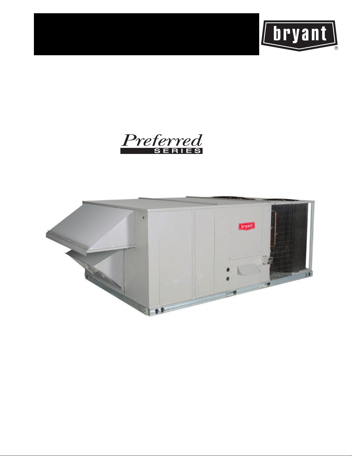
581J
Unit shown with optional economizer and power exhaust
HIGH-EFFICIENCY GAS HEAT/ELECTRIC COOLING
PACKAGED ROOFTOP
15 to 25 NOMINAL TONS
Product Data
TM
Copyright 2018 Bryant Corporation Form PDS581J-17-28-02
Page 2
TABLE OF CONTENTS
PAGE
FEATURES/BENEFITS. . . . . . . . . . . . . . . . . . . . . . . . . . . . . 3
MODEL NUMBER NOMENCLATURE . . . . . . . . . . . . . . . 4
CAPACITY RATINGS. . . . . . . . . . . . . . . . . . . . . . . . . . . . . . 5
PHYSICAL DATA . . . . . . . . . . . . . . . . . . . . . . . . . . . . . . . . . 7
OPTIONS AND ACCESSORIES . . . . . . . . . . . . . . . . . . . . 11
UNIT DIMENSIONS. . . . . . . . . . . . . . . . . . . . . . . . . . . . . . 16
ACCESSORY DIMENSIONS . . . . . . . . . . . . . . . . . . . . . . . 28
Your new 15 to 25 Ton Preferred Series Bryant rooftop unit (RTU) was designed by customers for customers. With a newly designed
cabinet that integrates “no-strip” screw collars, handled access panels, and more we’ve made your unit easy to install, easy to maintain, easy to use and reliable.
PERFORMANCE DATA. . . . . . . . . . . . . . . . . . . . . . . . . . . .31
TYPICAL WIRING DIAGRAM . . . . . . . . . . . . . . . . . . . . . .46
ELECTRICAL DATA . . . . . . . . . . . . . . . . . . . . . . . . . . . . . .50
SEQUENCE OF OPERATION . . . . . . . . . . . . . . . . . . . . . . .53
APPLICATION DATA. . . . . . . . . . . . . . . . . . . . . . . . . . . . . .55
GUIDE SPECIFICATIONS . . . . . . . . . . . . . . . . . . . . . . . . . .57
PAGE
Easy to install:
These new Preferred Series units are designed for dedicated factory-supplied vertical or horizontal air flow duct configurations. No
special field kits are required.
Easy to maintain:
Easy access handles by Bryant provide quick and easy access to all normally serviced components. Our “no-strip” screw system has
superior holding power and guides screws into position while preventing the screw from stripping the unit’s metal. Take accurate
pressure readings by reading system pressures with panels in place as compressors are strategically located to eliminate any air bypass.
Easy to use:
The newly designed, central terminal board by Bryant puts all your connections and troubleshooting points in one convenient place,
standard. Most low voltage connections are made to the same board and make it easy to find what you’re looking for and easy to access it.
Reliable:
Each unit comes with precision sized and tested scroll compressor that is internally protected from over temperature and pressures. In
addition, each refrigerant circuit is further protected with a high pressure and low pressure switch as well as containing a liquid line
filter drier. Each unit is factory tested prior to shipment to help ensure unit operation once properly installed.
2
Page 3

FEATURES/BENEFITS
• Two stage cooling capability with independent circuits and control.
• High performance copper tube / aluminum plate (RTPF) fin condenser and evaporator coils with optional coating.
• EER’s up to 12.0
• IEER’s up to 13.2 with single speed indoor fan motor and 13.8 with 2-speed/VFD indoor fan motor system
• Gas heating efficiencies up to 81% thermal efficiency.
• Dedicated vertical and horizontal air flow duct configuration models. No field kits required.
• Utility connections through the side or bottom. Bottom connections are also in an enclosed environment to help prevent water
entry. Field supplied couplings are required.
• Scroll compressors on all units. This makes service, stocking parts, replacement, and trouble-shooting easier.
• Precision sized TXV metering device on each refrigerant circuit.
• Easy-adjust, belt-drive motor available. Motor assembly also contains a fan belt break protection system on all models and reliable pillow block bearing system that allows lubrication thru front of the unit.
• Single-point gas/electrical connection.
• Sloped, composite drain pan sheds water; and won’t rust.
• Standardized controls and control box layout. Standardized components and controls make stocking parts and service easier.
• Clean, large, easy to use control box.
• Color-coded wiring.
• Large, laminated wiring and power wiring drawings which are affixed to unit make troubleshooting easy.
• Single, central terminal board for test and wiring connections.
• Fast-access, handled, panels for easy access on normally accessed service panels.
• “No-strip” screw system guides screws into the panel and captures them tightly without stripping the screw, the panel, or the unit.
• Mechanical cooling (125°F to 35°F/52°C to –2°C) standard on all models. Low ambient controller allows operation down to
–20°F/–29°C
• Redundant gas valve for 2-stage gas heating capacity control with induced-draft flue exhaust design to help ensure no flue gas can
escape into the indoor air stream.
• Exclusive IGC solid state gas controller for on board diagnostics with LED error code designation, burner control logic and
energy saving indoor fan motor delay.
• 2-in. (51mm) disposable filters on all units, with 4-in. (102 mm) filter track field-installed.
• Refrigerant filter-drier on each circuit.
• High and low pressure switches. Added reliability with high pressure switch and low pressure switch.
• Many factory-installed options ranging from air management economizers, 2 position dampers, manual outdoor air dampers, plus
convenience outlets, disconnect switch and smoke detectors.
• Factory-installed Perfect Humidity™ dehumidification system.
• Standard Parts Warranty: 10 year aluminized heat exchanger, 5 year compressor, 1 year others.
• Optional 2-Speed Indoor Fan Motor System utilizes a Variable Frequency Drive (VFD) to automatically adjust the indoor fan
motor speed between cooling stages. Available on 2-stage cooling models 17-28 with electromechanical controls or RTU Open.
3
Page 4
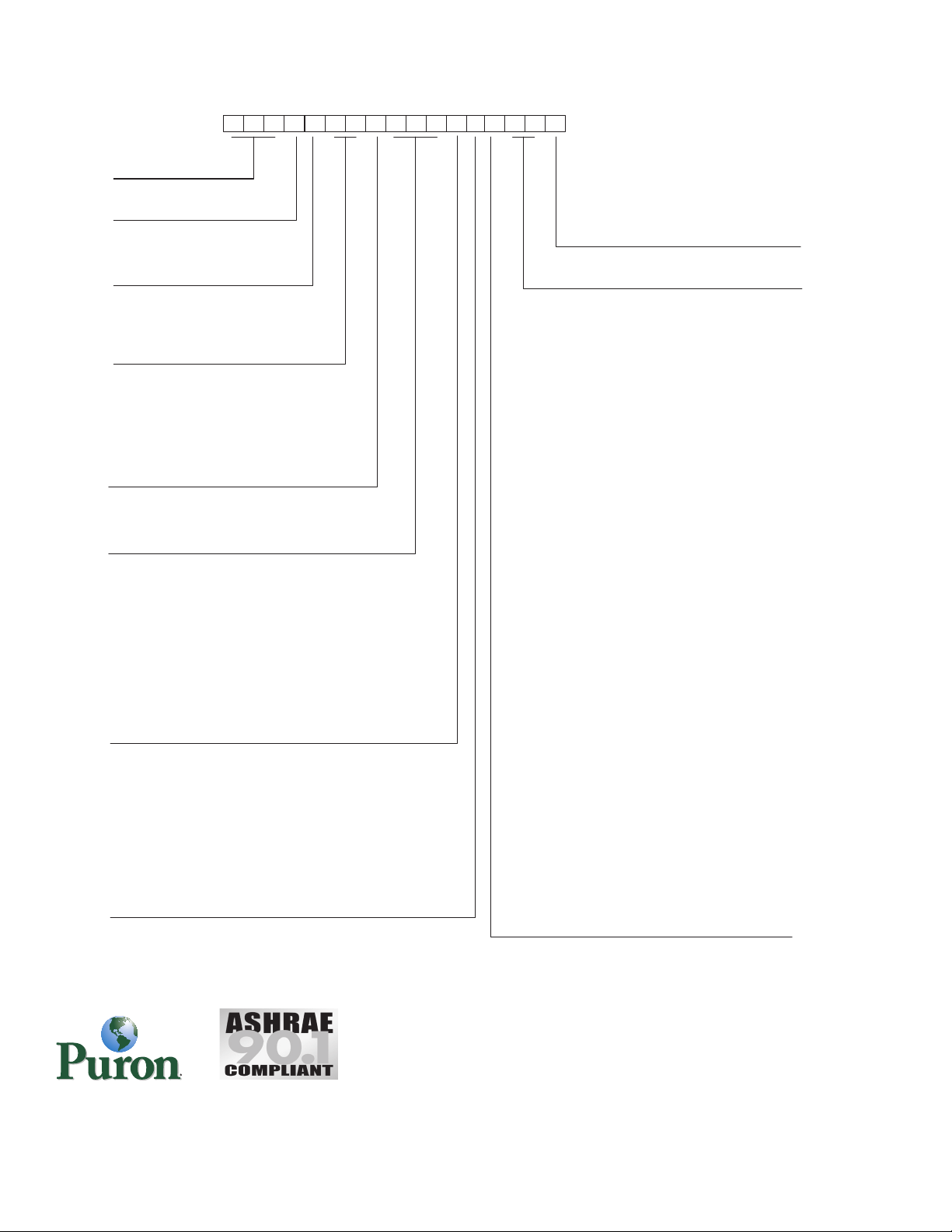
5 8 1 J E 1 7 D 3 1 0 A 1 A 0 A
Heat Level Input
200 = 220,000
310 = 310,000
400 = 400,000
1 2 3 4 5 6 7 8 9 1011121314151617
A
Outdoor Air Options
If Position 17 is A
If Position 17 is C or D
A
B
D
E
G
H
K
L
N
P
Q
= None
= Temperature Economizer, Low Leak EconoMi$er IV
w/ Barometric Relief (W7212 controller)
1
= Temperature Economizer, Low Leak EconoMi$er IV with
Centrifugal Power Exhaust (W7212 controller)
2
= Temperature Economizer, Low Leak EconoMi$er IV with
Barometric Relief and CO
2
(W7212 controller)
1
= Temeperature Economizer, Low Leak EconoMi$er IV with
Centrifugal Power Exhaust and CO
2
(W7212 controller)
2
= Enthalpy Economizer, Low Leak EconoMi$er IV with
Barometric Relief (W7212 controller)
1
= Enthalpy Economizer, Low Leak EconoMi$er IV with
Centrifugal Power Exhaust (W7212 controller)
2
= Enthalpy Economizer, Low Leak EconoMi$er with
Barometric relief and CO
2
(W7212 controller)
1
= Enthalpy Economizer, Low Leak EconoMi$er IV with
Centrifugal Power Exhaust CO
2
(W7212 controller)
2
= Manual Outdoor Air Damper1
= Motorized 2-Position Damper
1
A
B
D
E
G
H
K
L
N
U
V
W
X
= None
= Temperature Economizer, Low Leak EconoMi$er X with
Barometric Relief (W7220 controller)
1
= Temperature Economizer, Low Leak EconoMi$er X with
Centrifugal Power Exhaust (W7220 controller)
2
= Temperature Economizer, Low Leak EconoMi$er X with
Barometric Relief and CO
2
(W7220 controller)
1
= Temperature Economizer, Low Leak EconoMi$er X, with
Centrifugal Power Exhaust and CO
2
(W7220 controller)
2
= Enthalpy Economizer, Low Leak EconoMi$er X with
Barometric Relief (W7220 controller)
1
= Enthalpy Economizer, Low Leak EconoMi$er X with
Centrifugal Power Exhaust (W7220 controller)
2
= Enthalpy Economizer, Low Leak EconoMi$er X with
Barometric Relief and CO
2
(W7220 controller)
1
= Enthalpy Economizer, Low Leak with Centrifugal
Power Exhaust and CO
2
(W7220 controller)
2
= Ultra LOW LEAK Temperature EconoMi$er X with
Barometric Relief (W7220 controller)
1
= Ultra LOW LEAK Temperature EconoMi$er X with
Centrifugal Power Exhaust (W7220 controller)
2
= Ultra LOW LEAK Enthalpy EconoMi$er X with
Barometric Relief (W7220 controller)
1
= Ultra LOW LEAK Enthalpy EconoMi$er X with
Centrifugal Power Exhaust (W7220 controller)
2
1. Vertical and Horizontal Air Flow
2. Vertical Air Flow Only
Unit Type
581 = High Efficiency
Gas Heat RTU
Model
J (Puron
®
Refrigerant)
Voltage
E = 460-3-60
P = 208/230-3-60
T = 575-3-60
Cooling Tons
17 = 15 ton
20 = 17.5 ton
24 = 20 ton
28 = 25 ton
Refrig. System/Gas Heat Options
D = Two stage compressor Model
F = Two stage compressor Model and Stainless steel
gas heat exchanger
K = Two stage cooling with aluminum gas heat
exchanger and Perfect Humidity
M = Two stage cooling with stainless steel gas heat
exchanger and Perfect Humidity
Coil Options (Outdoor — Indoor — Hail Guard)
A = Al/CU - Al/Cu
B = Precoat Al/Cu - Al/Cu
C = E-coat Al/Cu - Al/Cu
D = E-coat Al/Cu - E-coat Al/Cu
E = Cu/Cu - Al/Cu
F = Cu/Cu - Cu/Cu
M = Al/Cu - Al/Cu – Louvered Hail Guard
N = Precoat Al/Cu - Al/Cu – Louvered Hail Guard
P = E-coat Al/Cu - Al/Cu – Louvered Hail Guard
Q = E-coat Al/Cu - E-coat Al/Cu – Louvered Hail Guard
R = Cu/Cu - Al/Cu – Louvered Hail Guard
S = Cu/Cu - Cu/Cu – Louvered Hail Guard
Indoor Fan Options
1 = Standard Static Option, Vertical
2 = Medium Static Option, Vertical
3 = High Static Option, Vertical
B = Medium Static, High Effy Motor, Vertical
C = High Static, High Effy Motor, Vertical
5 = Standard Static Option, Horizontal
6 = Medium Static Option, Horizontal
7 = High Static Option, Horizontal
F = Medium Static, High Effy Motor, Horizontal
G = High Staic, High Effy Motor, Horizontal
Packaging, Controls & Indoor Fan Motor
Speed Options
A = Standard Packaging, electro mech. controls that
require W7212 EconoMi$er IV
C = Standard Packaging, electro mech. controls that
require W7220 EconoMi$er X
D = Standard Packaging and 2-Speed Indoor Fan Motor
(VFD) Controller
Factory Installed Options
0A = None
MODEL NUMBER NOMENCLATURE
4
581J MODEL NUMBER NOMENCLATURE
Page 5
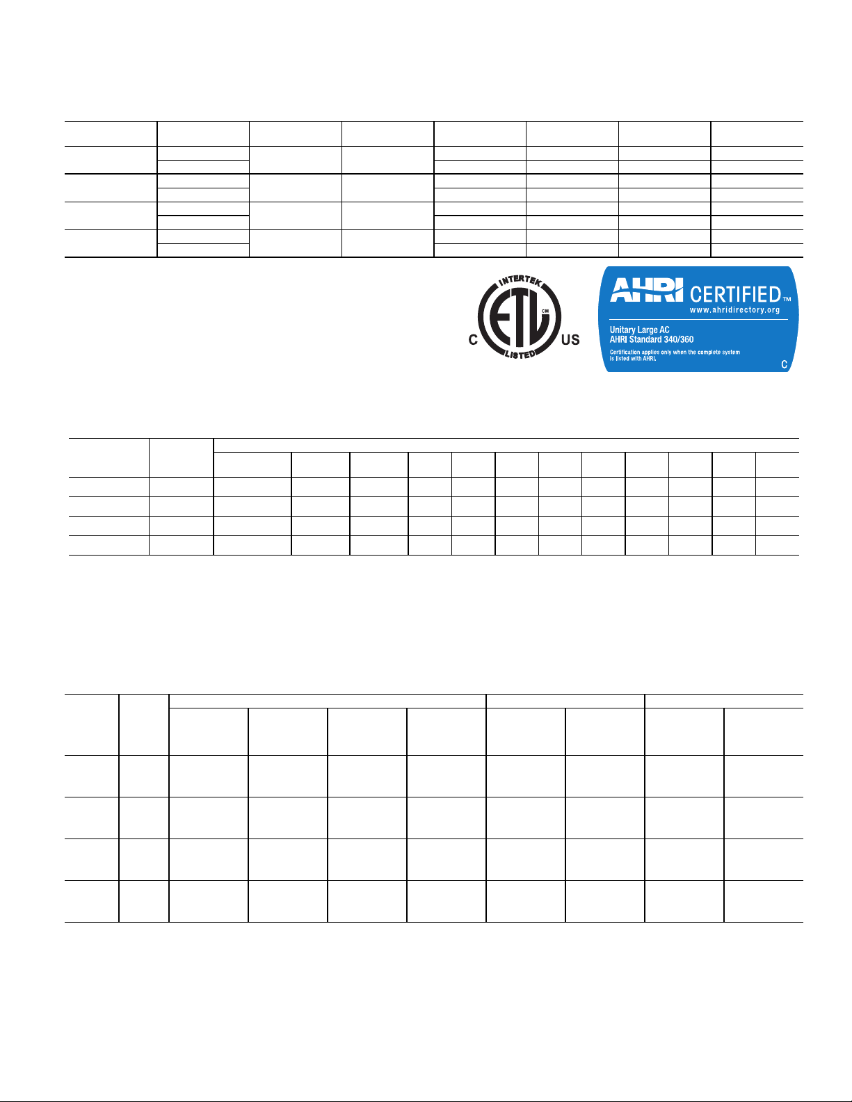
CAPACITY RATINGS
AHRI RATINGS (2-STAGE COOLING)
581J UNIT CONFIGURATION
17
20
24
28
LEGEND
AHRI — Air-Conditioning, Heating and Refrigeration Institute
EER — Energy Efficiency Ratio
IEER — Integrated Energy Efficiency Ratio
NOTE: 581J**28 horizontal units are only available with a 2-speed
option.
Vertic al
Horizontal 15.1 11.5 12.2 13.0
Vertic al
Horizontal 17.9 11.3 11.5 13.2
Vertic al
Horizontal 20.4 11.4 12.0 13.0
Vertic al
Horizontal 26.9 10.5 N/A 12.2
NOM. CAPACITY
(TONS)
15.0 174
17.5 202
20.0 232
25.0 282
NET COOLING
CAPACITY (MBH)
SOUND RATINGS TABLE
581J UNIT
17 2 84.1 96.2 84 92.6 92.0 84.0 80.0 82.0 78.7 76.5 72.2 65.4
20 2 84.1 96.2 84 92.6 92.0 84.0 80.0 82.0 78.7 76.5 72.2 65.4
24 2 86.5 99.6 87 96.2 95.6 87.5 84.2 84.2 81.7 77.9 73.2 66.3
28 2 85.9 103.0 86 101.0 97.0 88.0 84.0 83.0 80.7 77.4 73.4 67.3
LEGEND
dB — Decibel
NOTES:
1. Outdoor sound data is measured in accordance with AHRI.
2. Measurements are expressed in terms of sound power. Do not
compare these values to sound pressure values because sound
COOLING
STAGES
A-WEIGHTED LINEAR
AHRI-370
RATING
TOTAL POWER
(kW)
14.5 12.0 13.0 13.5
16.8 12.0 13.0 13.6
19.3 12.0 13.2 13.8
25.2 11.2 12.0 12.5
OUTDOOR SOUND (dB) AT 60Hz
31.5 63 125 250 500 1000 2000 4000 8000
pressure depends on specific environmental factors which normally do not match individual applications. Sound power values
are independent of the environment and therefore more accurate.
3. A-weighted sound ratings filter out very high and very low frequencies, to better approximate the response of “average” human
ear. A-weighted measurements for Bryant units are taken in
accordance with AHRI.
EER
IEER
(Single Speed)
IEER (2-Speed)
581J
UNIT
17
20
24
28
MINIMUM - MAXIMUM AIRFLOW RATINGS (CFM) — NATURAL GAS AND PROPANE
COOLING
HEAT
LEVEL
LOW
MED 3,880 7,750 3,880 7,750
HIGH 4,620 8,570 4,620 8,570
LOW
MED 3,880 9,300 3,880 9,300
HIGH 4,620 10,000 4,620 10,000
LOW
MED 3,880 11,630 3,880 11,630
HIGH 4,620 10,000 4,620 10,000
LOW
MED 3,880 15,500 3,880 15,500
HIGH 4,620 15,000 4,620 15,000
MINIMUM
SINGLE SPEED
FAN MOTOR
4,500 5,070 3,380 7,500
5,250 5,915 3,943 9,000
6,000 7,500 5,000 10,000
7,500 8,450 5,633 12,500
MINIMUM
2-SPEED FAN
MOTOR (AT
HIGH SPEED)
MINIMUM
2-SPEED FAN
MOTOR (AT
LOW SPEED)
MAXIMUM MINIMUM MAXIMUM MINIMUM MAXIMUM
ALUMINUM HEATING STAINLESS STEEL HEATING
3,000 8,250 3,000 8,250
3,000 11,000 3,000 11,000
3,000 11,000 3,000 11,000
3,000 16,500 3,000 16,500
5
Page 6
CAPACITY RATINGS (cont)
HEAT RATING TABLE — NATURAL GAS AND PROPANE
581J UNIT GAS HEAT
17
20
24
28
NOTES:
1. Heat ratings are for natural gas heat exchangers operated at or
below 2000 ft (610 m). For information on Propane or altitudes
above 2000 ft (610 m), see the Application Data section of this
book. Accessory Propane/High Altitude kits are also available.
LOW 220/178 176/142 20-55
HIGH 400/324 320/260 35-65
LOW 220/178 176/142 15-55
HIGH 400/324 320/260 30-65
LOW 220/178 176/142 15-55
HIGH 400/324 320/260 30-65
LOW 220/178 176/142 10-55
HIGH 400/324 320/260 20-65
AL/SS HEAT EXCHANGER
INPUT/OUTPUT
STAGE 1 (MBH)
INPUT/OUTPUT
STAGE 2 (MBH)
2. In the USA the input rating for altitudes above 2000 ft (610 m)
must be derated by 4% for each 1000 ft (305 m) above sea level.
In Canada, the input rating must be derated by 10% for altitudes of
2000 ft (610 m) to 4500 ft (1372 m) above sea level.
TEMPERATURE RISE
(F)
THERMAL EFFICIENCY
(%)
81%MED 310/251 248/200 30-60
81%MED 310/251 248/200 25-60
81%MED 310/251 248/200 20-60
81%MED 310/251 248/200 15-60
6
Page 7

PHYSICAL DATA
581J 15 TO 25 TON PHYSICAL DATA
581J UNIT 581J*17D 581J*20D 581J*24D 581J*28D
581J BASE UNIT TONS 15 15 17.5 17.5 20 20 25 25
581J BASE UNIT WEIGHT - lb
(kg)
REFRIGERATION SYSTEM
# Circuits / # Comp. / Type 2 / 2 / Scroll 2 / 2 / Scroll 2 / 2 / Scroll 2 / 2 / Scroll 2 / 2 / Scroll 2 / 2 / Scroll 2 / 2 / Scroll 2 / 2 / Scroll
R-410A Charge A/B (lbs) 17/16.4 24.5/25.7 17.5/16.8 25.5/25.5 23.8/23.1 30.0/30.7 24.9/27.7 35.1/35.4
Metering device TXV TXV TXV TXV TXV TXV TXV TXV
High-Pressure Trip / Reset
(psig)
Low-Pressure Trip / Reset
(psig)
EVAPORATOR COIL
Material Cu / Al Cu / Al Cu / Al Cu / Al Cu / Al Cu / Al Cu / Al Cu / Al
Tube Diameter (in.)
Rows / FPI 4 / 15 4 / 15 4 / 15 4 / 15 4 / 15 4 / 15 4 / 15 4 / 15
2
Total Face Area (ft
Condensate Drain Connection Size (in.)
) 22 22 22 22 26 26 26 26
PERFECT HUMIDITY™ COIL
Material
Tube Diameter
Rows / FPI 1 / 17 1 / 17 1 / 17 1 / 17
2
Total Face Area (ft
EVAPORATOR FAN AND
MOTOR VERTICAL SUPPLY
Motor Qty / Belt Qty /
Driver Type
Nominal /
Nameplate hp
) 22 22 26 26
Max bhp 2.9 2.9 3.7 3.7 N/A N/A 4.9 4.9
Rpm Range 514-680 514-680 622-822 622-822 N/A N/A 717-911 717-911
Max Blower/Shaft rpm 1200 1200 1200 1200 N/A N/A 1200 1200
Motor Frame Size 56 56 56 56 N/A N/A 56 56
STANDARD STATIC
Fan Qty / Type 2 / Centrifugal 2 / Centrifugal 2 / Centrifugal 2 / Centrifugal N/A N/A 2 / Centrifugal 2 / Centrifugal
Fan Diameter (in.) 15 X 15 15 X 15 15 X 15 15 X 15 N/A N/A 15 X 15 15 X 15
Motor Qty / Belt Qty /
Driver Type
Nominal /
Nameplate hp
Max bhp 3.7 3.7 4.9 4.9 N/A N/A N/A N/A
Rpm Range 679-863 679-863 713-879 713-879 N/A N/A N/A N/A
Max Blower/Shaft rpm 1200 1200 1200 1200 N/A N/A N/A N/A
Motor Frame Size 56 56 56 56 N/A N/A N/A N/A
MEDIUM STATIC
Fan Qty / Type 2 / Centrifugal 2 / Centrifugal 2 / Centrifugal 2 / Centrifugal N/A N/A N/A N/A
Fan Diameter (in.) 15 X 15 15 X 15 15 X 15 15 X 15 N/A N/A N/A N/A
Motor Qty / Belt Qty /
Driver Type
Nominal /
Nameplate hp
Max bhp 4.9 4.9 N/A N/A N/A N/A N/A N/A
Rpm Range 826-1009 826-1009 N/A N/A N/A N/A N/A N/A
Max Blower/Shaft rpm 1200 1200 N/A N/A N/A N/A N/A N/A
HIGH STATIC
Motor Frame Size 56 56 N/A N/A N/A N/A N/A N/A
Fan Qty / Type 2 / Centrifugal 2 / Centrifugal N/A N/A N/A N/A N/A N/A
Fan Diameter (in.) 15 X 15 15 X 15 N/A N/A N/A N/A N/A N/A
1892 (858) 2102 (953) 2247 (1019) 2292 (1040)
630 / 505 630 / 505 630 / 505 630 / 505 630 / 505 630 / 505 630 / 505 630 / 505
54 / 117 27 / 44 54 / 117 27 / 44 54 / 117 27 / 44 54 / 117 27 / 44
3
/8 RTPF
3
/
—
4
3
/8 RTPF
3
/
Cu / Al
3
/8 RTPF
3
/8 RTPF
3
4
/
4
—
3
/8 RTPF
3
/
Cu / Al
3
/8 RTPF
3
/8 RTPF
3
4
/
4
—
3
/8 RTPF
3
/
Cu / Al
3
/8 RTPF
3
/8 RTPF
3
4
/
4
3
/8 RTPF
Cu / Al
3
—
/8 RTPF
1 / 1 /Belt 1 / 1 /Belt 1 / 1 /Belt 1 / 1 /Belt N/A N/A 1 / 1 /Belt 1 / 1 /Belt
2.9 2.9 3.7 3.7 N/A N/A 5.25 5.25
1 / 1 /Belt 1 / 1 /Belt 1 / 1 /Belt 1 / 1 /Belt N/A N/A N/A N/A
3.7 3.7 5.25 5.25 N/A N/A N/A N/A
1 / 1/ BELT 1 / 1/ BELT N/A N/A N/A N/A N/A N/A
5.25 5.25 N/A N/A N/A N/A N/A N/A
3
/
4
7
Page 8

PHYSICAL DATA (cont)
581J 15 TO 25 TON PHYSICAL DATA (CONT)
581J UNIT 581J*17D 581J*20D 581J*24D 581J*28D
EVAPORATOR FAN AND
MOTOR VERTICAL SUPPLY
(CONT)
Motor Qty / Belt Qty /
Driver Type
Nominal /
Nameplate hp
Max bhp N/A N/A N/A N/A
Rpm Range N/A N/A N/A N/A 690-863 690-863 N/A N/A
Max Blower/Shaft rpm N/A N/A N/A N/A 1200 1200 N/A N/A
Motor Frame Size N/A N/A N/A N/A 184T 184T N/A N/A
Fan Qty / Type N/A N/A N/A N/A 2 / Centrifugal 2 / Centrifugal N/A N/A
Fan Diameter (in.) N/A N/A N/A N/A 15 X 15 15 X 15 N/A N/A
STANDARD STATIC - HIGH EFFCY
Motor Qty / Belt Qty /
Driver Type
Nominal /
Nameplate hp
Max bhp N/A N/A N/A N/A
Rpm Range N/A N/A N/A N/A 835-1021 835-1021 913-1116 913-1116
Max Blower/Shaft rpm N/A N/A N/A N/A 1200 1200 1200 1200
Motor Frame Size N/A N/A N/A N/A 184T 184T 184T 184T
Fan Qty / Type N/A N/A N/A N/A 2 / Centrifugal 2 / Centrifugal 2 / Centrifugal 2 / Centrifugal
N/A N/A N/A N/A 1 / 1 /Belt 1 / 1 /Belt N/A N/A
N/A N/A N/A N/A 5.0 5.0 N/A N/A
6.5/ 6.9/ 7.0/
8.3
N/A N/A N/A N/A 1 / 1/ Belt 1 / 1/ Belt 1 / 1/ Belt 1 / 1/ Belt
N/A N/A N/A N/A 5.0 5.0 5.0 5.0
6.5/ 6.9/ 7.0/
8.3
6.5/ 6.9/ 7.0/
8.3
6.5/ 6.9/ 7.0/
8.3
N/A N/A
6.5/ 6.9/ 7.0/
8.3
6.5/ 6.9/ 7.0/
8.3
Fan Diameter (in.) N/A N/A N/A N/A 15 X 15 15 X 15 15 X 15 15 X 15
MEDIUM STATIC - HIGH EFFICIENCY
Motor Qty / Belt Qty /
Driver Type
Nominal Nameplate
H.p.
Max Bhp (208/230/460/
575v)
Rpm Range N/A N/A 882-1078 882-1078 941-1176 941-1176 941-1176 941-1176
Max Blower/shaft Rpm N/A N/A 1200 1200 1200 1200 1200 1200
EFFICIENCY
Motor Frame Size N/A N/A 184T 184T 213T 213T 213T 213T
HIGH STATIC- HIGH
Fan Qty / Type N/A N/A 2 / Centrifugal 2 / Centrifugal 2 / Centrifugal 2 / Centrifugal 2 / Centrifugal 2 / Centrifugal
Fan Diameter (In) N/A N/A 15 X 15 15 X 15 15 X 15 15 X 15 15 X 15 15 X 15
EVAPORATOR FAN AND
MOTOR HORIZONTAL SUPPLY
Motor Qty / Belt Qty /
Driver Type
Nominal /
Nameplate hp
Max bhp 2.9 2.9 3.7 3.7 N/A N/A N/A N/A
Rpm Range 514-680 514-680 622-822 622-822 N/A N/A N/A N/A
Max Blower/Shaft rpm 1100 1100 1100 1100 N/A N/A N/A N/A
Motor Frame Size 56 56 56 56 N/A N/A N/A N/A
STANDARD STATIC
Fan Qty / Type 2 / Centrifugal 2 / Centrifugal 2 / Centrifugal 2 / Centrifugal N/A N/A N/A N/A
Fan Diameter (in.) 18 x 15/15 X 11 18 x 15/15 X 11 18 x 15/15 X 11 18 x 15/15 X 11 N/A N/A N/A N/A
Motor Qty / Belt Qty /
Driver Type
Nominal /
Nameplate hp
Max bhp 3.7 3.7 4.9 4.9 N/A N/A N/A N/A
Rpm Range 614-780 614-780 713-879 713-879 N/A N/A N/A N/A
Max Blower/Shaft rpm 1100 1100 1100 1100 N/A N/A N/A N/A
Motor Frame Size 56 56 56 56 N/A N/A N/A N/A
MEDIUM STATIC
Fan Qty / Type 2 / Centrifugal 2 / Centrifugal 2 / Centrifugal 2 / Centrifugal N/A N/A N/A N/A
Fan Diameter (in.) 18 x 15/15 X 11 18 x 15/15 X 11 18 x 15/15 X 11 18 x 15/15 X 11 N/A N/A N/A N/A
N/A N/A 1 / 1 /Belt 1 / 1 /Belt 1 / 1 /Belt 1 / 1 /Belt 1 / 1 /Belt 1 / 1 /Belt
N/A N/A 5.0 5.0 7.5 7.5 7.5 7.5
N/A N/A
1 / 1 /Belt 1 / 1 /Belt 1 / 1 /Belt 1 / 1 /Belt N/A N/A N/A N/A
2.9 2.9 3.7 3.7 N/A N/A N/A N/A
1 / 1 /Belt 1 / 1 /Belt 1 / 1 /Belt 1 / 1 /Belt N/A N/A N/A N/A
3.7 3.7 5.25 5.25 N/A N/A N/A N/A
6.5/ 6.9/ 7.0/
8.3
6.5/ 6.9/ 7.0/
8.3
10.5/11.9/11.9/1110.5/11.9/11.9/1110.5/11.9/11.9/1110.5/11.9/11.9/
11
8
Page 9
581J 15 TO 25 TON PHYSICAL DATA (CONT)
581J UNIT 581J*17D 581J*20D 581J*24D 581J*28D
Motor Qty / Belt Qty /
Driver Type
Nominal /
Nameplate hp
Max bhp 4.9 4.9 N/A N/A N/A N/A N/A N/A
Rpm Range 746-912 746-912 N/A N/A N/A N/A N/A N/A
Max Blower/Shaft rpm 1100 1100 N/A N/A N/A N/A N/A N/A
HIGH STATIC
Motor Frame Size 56 56 N/A N/A N/A N/A N/A N/A
Fan Qty / Type 2 / Centrifugal 2 / Centrifugal N/A N/A N/A N/A N/A N/A
Fan Diameter (in.) 18 x 15/15 X 11 18 x 15/15 X 11 N/A N/A N/A N/A N/A N/A
Motor Qty / Belt Qty /
Driver Type
Nominal /
Nameplate hp
Max bhp N/A N/A N/A N/A
Rpm Range N/A N/A N/A N/A 690-863 690-863 N/A N/A
Max Blower/Shaft rpm N/A N/A N/A N/A 1200 1200 N/A N/A
EFFICIENCY
Motor Frame Size N/A N/A N/A N/A 184T 184T N/A N/A
Fan Qty / Type N/A N/A N/A N/A 2 / Centrifugal 2 / Centrifugal N/A N/A
STANDARD STATIC - HIGH
Fan Diameter (in.) N/A N/A N/A N/A 18 x 15/15 X 11 18 x 15/15 X 11 N/A N/A
Motor Qty / Belt Qty /
Driver Type
Nominal /
Nameplate hp
Max bhp N/A N/A N/A N/A
Rpm Range N/A N/A N/A N/A 835-1021 835-1021 755-923 755-923
Max Blower/Shaft rpm N/A N/A N/A N/A 1100 1100 1100 1100
EFFICIENCY
Motor Frame Size N/A N/A N/A N/A 184T 184T 184T 184T
MEDIUM STATIC - HIGH
Fan Qty / Type N/A N/A N/A N/A 2 / Centrifugal 2 / Centrifugal 2 / Centrifugal 2 / Centrifugal
Fan Diameter (in.) N/A N/A N/A N/A 18 x 15/15 X 11 18 x 15/15 X 11 18 x 15/15 X 11 18 x 15/15 X 11
Motor Qty / Belt Qty /
Driver Type
Nominal /
Nameplate hp
Max bhp N/A N/A
Rpm Range N/A N/A 835-1021 835-1021 941-1100 941-1100 906-1100 906-1100
Max Blower/Shaft rpm N/A N/A 1100 1100 1100 1100 1100 1100
EFFICIENCY
Motor Frame Size N/A N/A 184T 184T 213T 213T 213T 213T
HIGH STATIC- HIGH
Fan Qty / Type N/A N/A 2 / Centrifugal 2 / Centrifugal 2 / Centrifugal 2 / Centrifugal 2 / Centrifugal 2 / Centrifugal
Fan Diameter (in.) N/A N/A 18 x 15/15 X 11 18 x 15/15 X 11 18 x 15/15 X 11 18 x 15/15 X 11 18 x 15/15 X 11 18 x 15/15 X 11
COND. COIL (CIRCUIT A)
Coil Type RTPF RTPF RTPF RTPF RTPF RTPF RTPF RTPF
Coil Length (in.) 70 70 72 72 82 82 95 95
Coil Height (in.) 44 44 44 44 52 52 52 52
Rows / fpi 2 /17 2 /17 2 /17 2 /17 2 /17 2 /17 2 /17 2 /17
2
Total Face Area (Ft
) 21.4 21.4 22.0 22.0 29.6 29.6 34.3 34.3
COND. COIL (CIRCUIT B)
Coil Type RTPF RTPF RTPF RTPF RTPF RTPF RTPF RTPF
Coil Type 70 70 64 64 80 80 95 95
Coil Length (in.) 44 44 44 44 52 52 52 52
Coil Height (in.) 2 /17 2 /17 2 /17 2 /17 2 /17 2 /17 2 /17 2 /17
Rows / fpi 21.4 21.4 19.5 19.5 29.6 29.6 34.3 34.3
COND. FAN / MOTOR
Qty / Motor Drive Type 3 / direct 3 / direct 4 / direct 4 / direct 4/ direct 4/ direct 6 / direct 6 / direct
Motor Hp / Rpm
Fan Diameter (in.) 22 22 22 22 22 22 22 22
FILTERS
RA Filter # / Size (in.) 6 / 20 x 25 x 2 6 / 20 x 25 x 2 6 / 20 x 25 x 2 6 / 20 x 25 x 2 9 / 16 x 25 x 2 9 / 16 x 25 x 2 9 / 16 x 25 x 2 9 / 16 x 25 x 2
OA Inlet Screen # / Size (in.) 4 / 16 x 25 x 1 4 / 16 x 25 x 1 4 / 16 x 25 x 1 4 / 16 x 25 x 1 4 / 16 x 25 x 1 4 / 16 x 25 x 1 4 / 16 x 25 x 1 4 / 16 x 25 x 1
1 / 1 /Belt 1 / 1 /Belt N/A N/A N/A N/A N/A N/A
4.9 4.9 N/A N/A N/A N/A N/A N/A
N/A N/A N/A N/A 1 / 1 /Belt 1 / 1 /Belt N/A N/A
N/A N/A N/A N/A 5.0 5.0 N/A N/A
6.5/ 6.9/ 7.0/
8.3
6.5/ 6.9/ 7.0/
8.3
N/A N/A
N/A N/A N/A N/A 1 / 1 /Belt 1 / 1 /Belt 1 / 1 /Belt 1 / 1 /Belt
N/A N/A N/A N/A 5.0 5.0 5.0 5.0
6.5/ 6.9/ 7.0/
8.3
6.5/ 6.9/ 7.0/
8.3
6.5/ 6.9/ 7.0/
8.3
6.5/ 6.9/ 7.0/
N/A N/A 1 / 1 /Belt 1 / 1 /Belt 1 / 1 /Belt 1 / 1 /Belt 1 / 1 /Belt 1 / 1 /Belt
N/A N/A 5.0 5.0 7.5 7.5 7.5 7.5
1
/4 / 1100
1
/4 / 1100
6.5/ 6.9/ 7.0/
8.3
1
/4 / 1100
6.5/ 6.9/ 7.0/
8.3
1
/4 / 1100
10.5/11.9/11.9/1110.5/11.9/11.9/1110.5/11.9/11.9/1110.5/11.9/11.9/
1
/4 / 1100
1
/4 / 1100
1
/4 / 1100
1
/4 / 1100
8.3
11
9
Page 10

PHYSICAL DATA (cont)
581J 15 TO 25 TON PHYSICAL DATA (CONT)
581J UNIT 581J*17D 581J*20D 581J*24D 581J*28D
GAS CONNECTION
Number of Gas Valves 1111
Nat. gas supply line press
(in. wg) / (PSIG)
LP supply line press (in. wg) /
(PSIG)
HEAT ANTICIPATOR SETTING
(AMPS)
1st stage 0.14 0.14 0.14 0.14
2nd stage 0.14 0.14 0.14 0.14
NATURAL GAS HEAT
# of stages / # of burners
(total)
Connection Size (in.)
LOW
Rollout switch opens /
closes (F)
Temperature Rise (F) 25 - 55 25 - 55 25 - 55 25 - 55
# of stages / # of burners
(total)
Connection Size (in.)
MED
Rollout switch opens /
closes (F)
Temperature Rise (F) 30- 60 30- 60 30- 60 30- 60
# of stages / # of burners
(total)
Connection Size (in.)
HIGH
Rollout switch opens /
closes (F)
Temperature Rise (F) 35- 65 35- 65 35- 65 35- 65
LIQUID PROPANE HEAT
# of stages / # of burners
(total)
Connection Size (in.)
LOW
Rollout switch opens /
closes (F)
Temperature Rise (F) 25 - 55 25 - 55 25 - 55 25 - 55
# of stages / # of burners
(total)
Connection Size (in.)
MED
Rollout switch opens /
closes (F)
Temperature Rise (F) 30- 60 30- 60 30- 60 30- 60
# of stages / # of burners
(total)
Connection Size (in.)
HIGH
Rollout switch opens /
closes (F)
Temperature Rise (F) 35- 65 35- 65 35- 65 35- 65
5 -13 / 0.18-0.47 5 -13 / 0.18-0.47 5 -13 / 0.18-0.47 5 -13 / 0.18-0.47
11-13 / 0.40-0.47 11-13 / 0.40-0.47 11-13 / 0.40-0.47 11-13 / 0.40-0.47
2 / 5 2 / 5 2 / 5 2 / 5
3
/4 NPT
3
/4 NPT
3
/4 NPT
3
/4 NPT
195 / 115 195 / 115 195 / 115 195 / 115
2 / 7 2 / 7 2 / 7 2 / 7
3
/4 NPT
3
/4 NPT
3
/4 NPT
3
/4 NPT
195 / 115 195 / 115 195 / 115 195 / 115
2 / 10 2 / 10 2 / 10 2 / 10
3
/4 NPT
3
/4 NPT
3
/4 NPT
3
/4 NPT
195 / 115 195 / 115 195 / 115 195 / 115
2 / 5 2 / 5 2 / 5 2 / 5
3
/4 NPT
3
/4 NPT
3
/4 NPT
3
/4 NPT
195 / 115 195 / 115 195 / 115 195 / 115
2 / 7 2 / 7 2 / 7 2 / 7
3
/4 NPT
3
/4 NPT
3
/4 NPT
3
/4 NPT
195 / 115 196 / 115 197 / 115 198 / 115
2 / 10 2 / 10 2 / 10 2 / 10
3
/4 NPT
3
/4 NPT
3
/4 NPT
3
/4 NPT
195 / 115 195 / 115 195 / 115 195 / 115
10
Page 11
OPTIONS AND ACCESSORIES
ITEM OPTION* ACCESSORY
CABINET
Dedicated Vertical Air Flow Duct
Configuration
Dedicated Horizontal Air Flow
Duct Configuration
Hinged Access Panels
COIL OPTIONS
Cu/Cu (Indoor) Coils
Premium, E-coated Outdoor Coils
Pre-coated (outdoor and indoor)
Coils
HUMIDITY CONTROL
Perfect Humidity™ Adaptive
Dehumidification
System
CONDENSER PROTECTION
Condenser Coil Louvered Hail
Guard
CONTROLS
RTU Open Multi-Protocol
Controller
Thermostats, Temperature
Sensors, and Subbase
Smoke Detector (Supply and/or
Return Air)
Horn/Strobe Annunciator
Time Guard II Compressor Delay
Control Circuit
Phase Monitor
ECONOMIZERS AND OUTDOOR
AIR DAMPERS
Economi$er IV for ElectroMechanical Controls — Non-FDD
(Standard Air Leak Damper
Models)
EconoMi$er
(Standard and
Damper Models)
EconoMi$er X For ElectroMechanical Controls, Complies
with
Leak air damper models)
Motorized 2 Position
5
2 for DDC controls
Ultra
Low Leak Air
5, 6
FDD. (Standard and
Outdoor-Air
Ultra
5
Damper
Manual
Outdoor-Air Damper
(25%)
Barometric
Barometric Hood (Horizontal
economizer)
Relief
1
Power Exhaust (Prop Design)
Low
†
X
X
X
X
X
X
X
XX
X
X
XX
X
X
X
XX
XX
XX
XX
X
XX
X
XX
ITEM OPTION* ACCESSORY
ECONOMIZER SENSORS AND IAQ
DEVICES
Single Dry Bulb Temperature
Sensors
Differential Dry Bulb Temperature
Sensors
Single Enthalpy Sensors
Differential Enthalpy Sensors
Wall or Duct Mounted CO
Sensor
Unit Mounted CO
2
2
2
2
Sensor
2
2
2
2
4-in. Filter Track Assembly
XX
X
XX
X
X
X
X
GAS HEAT
Propane Conversion Kit
Stainless Steel Heat Exchanger
High Altitude Conversion Kit
Flue Discharge Deflector
X
X
X
X
INDOOR MOTOR AND DRIVE
Multiple Motor and Drive
Packages
2-speed Indoor Fan Motor
System w/VFD Controller
(2-stage Cooling Only with
Electrical Mechanical and RTU
Open Controls)
Display Kit for 2-Speed Indoor
Fan Motor System with VFD
X
X
X
LOW AMBIENT CONTROL
Winter Start Kit
Motormaster
Controller to –20°F
2
®
Head Pressure
3
X
X
POWER OPTIONS
Powered Convenience Outlet
Unpowered Convenience Outlet
(125 amp Factory-Installed, 20
amp Field-Installed)
Non-Fused Disconnect
4
X
XX
X
ROOF CURBS
Roof Curb 14-in. (356 mm)
Roof Curb 24-in. (610 mm)
*Factory-installed option.
†Field-installed accessory.
NOTES:
1. Included with economizer.
2. Sensors used to optimize economizer performance.
3. See application data for assistance.
4. Non-fused disconnect switch cannot be used when MOCP electrical rating
exceeds 70 amps at 460/575 volt and 150 amps at 208/230
volt. Bryant Packaged RTUBuilder selects this automatically.
5. FDD (Fault Detection and Diagnostic) capability per California Title 24 section
120.2.
6. Models with RTU Open controls comply with California Title 24 Fault Detection
and Diagnostic (FDD).
X
X
†
11
Page 12

OPTIONS AND ACCESSORIES (cont)
Economizer (dry-bulb or enthalpy) — Economizers
save money. They bring in fresh, outside air for ventilation; and
provide cool, outside air to cool your building. This is the preferred method of low-ambient cooling. When coupled to CO
sensors, economizers can provide even more savings by coupling the ventilation air to only that amount required.
Economizers are available, installed and tested by the factory,
with either enthalpy or dry-bulb temperature inputs. Additional
sensors are available as accessories to optimize the economizers. Economizers include a powered exhaust system to help
equalize building pressures.
Economizers include gravity controlled barometric relief that
helps equalize building pressure and ambient air pressures.
This can be a cost effective solution to prevent building pressurization. Economizers are available in Ultra Low Leak and
standard low leak versions. Economizers can be factoryinstalled or easily field-installed.
Optional Perfect Humidity™ Adaptive Dehumidification System —
system is an all-inclusive factory installed option that can be
ordered with any Preferred Series 581J 17-28 rooftop unit.
This system expands the envelope of operation of Bryant’s Preferred Series rooftop products to provide unprecedented flexibility to meet year round comfort conditions.
The Perfect Humidity dehumidification system has the industry’s only dual dehumidification mode setting. The Perfect
Humidity system includes two new modes of operation.
The Preferred Series 581J 17-28 rooftop coupled with the Perfect Humidity system is capable of operating in normal design
cooling mode, subcooling mode, and hot gas reheat mode. Normal design cooling mode is when the unit will operate under its
normal sequence of operation by cycling compressors to maintain comfort conditions.
Subcooling mode will operate to satisfy part load type conditions when the space requires combined sensible and a higher
proportion of latent load control. Hot Gas Reheat mode will
operate when outdoor temperatures diminish and the need for
latent capacity is required for sole humidity control. Hot Gas
Reheat mode will provide neutral air for maximum dehumidification operation.
Bryant’s Perfect Humidity dehumidification
Thru-the-Base Connections — Thru-the-base provisions/
connection points are available as standard with every unit.
When bottom connections are required, field furnished couplings are required.
Hinged Access Panels — Allows access to unit’s major
components with specifically designed hinged access panels.
Panels are filter, control box, indoor fan motor.
Cu/Cu (Indoor) Coils (3-Phase Models Only) — Copper
fins and copper tubes are mechanically bonded to copper tubes
and copper tube sheets. A polymer strip prevents coil assembly
from contacting the sheet metal coil pan to minimize potential
for galvanic corrosion between coil and pan.
E-coated (Outdoor and Indoor) Coils — A flexible
epoxy polymer coating uniformly applied to all coil surface areas
without material bridging between fins. Coating process shall
ensure complete coil encapsulation of tubes, fins and headers.
Pre-Coated Outdoor Coils — A durable epoxy-phenolic
2
coating to provide protection in mildly corrosive coastal environments. The coating minimizes galvanic action between dissimilar metals. Coating is applied to the aluminum fin stock
prior to the fin stamping process to create an inert barrier
between the aluminum fin and copper tube.
Condenser Coil Louvered Hail Guard — Sleek, lou-
vered panels protect the condenser coil from hail damage, foreign objects, and incidental contact. This can be purchased as a
factory installed option or as a field installed accessory.
Smoke Detectors — Trust the experts. Smoke detectors
make your application safer and your job easier. Bryant smoke
detectors immediately shut down the rooftop unit when smoke
is detected. They are available, installed by the factory, for supply air, return air, or both.
Optional Stainless Steel Heat Exchanger — The
stainless steel heat exchanger option provides the tubular heat
exchanger be made out of a minimum 20 gauge type 409 stainless steel for applications where the mixed air to the heat exchanger is expected to drop below 45°F (7°C). Stainless steel
may be specified on applications where the presence of airborne contaminants require its use (applications such as paper
mills) or in area with very high outdoor humidity that may result in severe condensation in the heat exchanger during cooling operation.
Convenience Outlet (Powered or Un-powered) —
Reduce service and/or installation costs by including a convenience outlet in your specification. Bryant will install this service feature at our factory. Provides a convenient, 15 amp, 115v
GFCI receptacle with “Wet in Use” cover. The “powered”
option allows the installer to power the outlet from the line side
of the disconnect side as required by code. The “unpowered”
option is to be powered from a separate 115/120v power
source.
Non-Fused Disconnect — This OSHA-compliant, factory-
installed, safety switch allows a service technician to locally
secure power to the rooftop.
When selecting a factory-installed non-fused disconnect, note
they are sized for unit as ordered from the factory. The sizing of
these does not accommodate any power exhaust devices, etc.
HACR Breaker — These manual reset devices provide
overload and short circuit protection for the unit. Factory wired
and mounted with the units with access cover to help provide
environment protection.
On 575V applications, HACR breaker can only be used with
WYE power distribution systems. Use on Delta power distribution systems is prohibited.
Foil Faced Insulated Cabinet — Cabinet is fully insulated
with non-fibrous, foil faced cleanable insulation that is secured
and encapsulated in unit design.
12
Page 13

RTU Open Protocol Controller — Connect the rooftop to
an existing BAS without needing complicated translators or
adapter modules using the RTU Open controller. This new controller speaks the 4 most common building automation system
languages (BACnet
1
, Modbus2, N2, and LonWorks3). Use this
controller when you have an existing BAS.
Condensate Overflow Switch (Factory-Installed
Option) —
condensate level in the drain pan and shuts down compression
operation when overflow conditions occur. It includes:
• Indicator light - solid red (more than 10 seconds on water
contact - compressors disabled), blinking red (sensor disconnected)
• 10 second delay to break - eliminates nuisance trips from
splashing or waves in pan (sensor needs 10 seconds of constant water contact before tripping)
• Disables the compressor(s) operation when condensate plug
is detected, but still allows fans to run for Economizer.
This sensor and related controller monitors the
Power Exhaust with Barometric Relief — Superior
internal building pressure control. This field-installed accessory or factory-installed option may eliminate the need for
costly, external pressure control fans.
Low Ambient Controller — The low ambient controller is a
head pressure controller kit that is designed to maintain the unit’s
condenser head pressure during periods of low ambient cooling
operation. This device should be used as an alternative to economizer free cooling, not when economizer usage is neither appropriate nor desired. The low ambient controller will either cycle
the outdoor fan motors or operate them at reduced speed to maintain the unit operation, depending on the model. This controller
allows cooling operation down to 0°F (–18°C) ambient conditions.
Motorized 2-Position Damper — The new Bryant 2-posi-
tion, motorized outdoor air damper admits up to 100% outside
air. Using reliable, gear-driven technology, the 2-position
damper opens to allow ventilation air and closes when the rooftop stops, stopping unwanted infiltration.
Manual OA Damper — Manual outdoor air dampers are an
economical way to bring in ventilation air. The dampers are
available in 25% versions.
2-Speed Indoor Fan Motor System — Bryant’s 2-Speed
Indoor Fan Motor System saves energy and installation time by
utilizing a Variable Frequency Drive (VFD) to automatically
adjust the indoor fan motor speed in sequence with the units
cooling operation. Per ASHRAE 90.1 2016 standard section
6.4.3.10.b, during the first stage of cooling operation the VFD
will adjust the fan motor to provide
lished for the unit. When a call for the second stage of cooling is
required, the VFD will allow the total cfm for the unit established
(100%). During the heating mode the VFD will allow total
design cfm (100%) operation and during the ventilation mode
the VFD will allow operation to
1. BACnet is a registered trademark of ASHRAE (American Society of Heating, Refrigerating and Air-Conditioning Engineers).
2. Modbus is a registered trademark of Schneider Electric.
3. LonWorks is a registered trademark of Echelon Corporation.
2
/3 of the total cfm estab-
2
/3 of total cfm.
Compared to single speed indoor fan motor systems, Bryant’s 2Speed Indoor Fan Motor System can save substantial energy,
25%+*, versus single speed indoor fan motor systems.
*Data based on .10 ($/kWh) in an office application utilizing
Bryant’s HAP 4.6 simulation software program.
The VFD used in Bryant’s 2-Speed Indoor Fan Motor System
has soft start capabilities to slowly ramp up the speeds, thus eliminating any high inrush air volume during initial start-up. It also
has internal over current protection for the fan motor and a field
installed display kit that allows adjustment and in depth diagnostics of the VFD.
This 2-Speed Indoor Fan Motor System is available on models
with 2-stage cooling operation with electrical mechanical or
RTU Open, Multi Protocol controls. Both space sensor and conventional thermostats controls can be used to provide accurate
control in any application.
The 2-Speed Indoor Fan Motor System is very flexible for initial
fan performance set up and adjustment. The standard factory
shipped VFD is pre-programmed to automatically stage the fan
speed between the first and second stage of cooling. The unit fan
performance static pressure and cfm can be easily adjusted using
the traditional means of pulley adjustments. The other means to
adjust the unit static and cfm performance is to utilize the field
installed Display Kit and adjust the frequency and voltage in the
VFD to required performance requirements. In either case, once
set up, the VFD will automatically adjust the speed between the
cooling stage operations.
Alternate Motors and Drives — Some applications need
larger horsepower motors, some need more airflow, and some
need both. Regardless of the case, your Bryant expert has a factory-installed combination to meet your application. A wide
selection of motors and pulleys (drives) are available, factoryinstalled, to handle nearly any application.
Barometric Hood — For Horizontal Economizer applica-
tions where relief damper is installed in duct work. This kit provides the needed protection.
Differential Enthalpy Sensor — The differential
enthalpy sensor is comprised of an outdoor and return air
enthalpy sensors to provide differential.
Wall or duct mounted CO2 Sensor — The IAQ sensor
shall be available in duct or wall mount. The sensor provides
demand ventilation indoor air quality (IAQ) control.
Time Guard II Control Circuit — This accessory pro-
tects your compressor by preventing short-cycling in the event
of some other failure, prevents the compressor from restarting
for 30 seconds after stopping. Not required with PremierLink,
RTU Open, or authorized commercial thermostats.
Propane Conversion Kit — Convert your gas heat rooftop
from standard natural gas operation to Propane using this fieldinstalled kit.
High Altitude Heating — High altitudes have less
oxygen, which affects the fuel/air mixture in heat exchangers.
In order to maintain a proper fuel/air mixture, heat exchangers
operating in altitudes above 2000 ft (610 m) require different
orifices. To select the correct burner orifices or determine the
heat capacity for a high altitude application, use either the
selection software, or the unit’s service manual. High altitudes
have less oxygen, which means heat exchangers need less fuel.
The new gas orifices in this field-installed kit make the
13
Page 14

OPTIONS AND ACCESSORIES (cont)
necessary adjustment for high altitude applications. They
restore the optimal fuel to air mixture and maintain healthy
combustion on altitudes above 2000 ft (610 m).
NOTE: Typical natural gas heating value ranges from 975 to
1050 Btu/ft
down approximately 1.7% per every thousand feet elevation.
Standard factory orifices can typically be used up to 2000 ft
(610 m) elevation without any operational issues.
3
at sea level nationally. The heating value goes
Flue Discharge Deflector — The flue discharge deflector is
a useful accessory when flue gas recirculation is a concern. By
venting the flue discharge upwards, the deflector minimizes the
chance for a neighboring unit to intake the flue exhaust.
Winter Start Kit — The winter start kit by Bryant extends
the low ambient limit of your rooftop to 25°F (–4°C). The kit
bypasses the low pressure switch, preventing nuisance tripping
of the low pressure switch. Other low ambient precautions may
still be prudent.
Motormaster® Head Pressure Controller — The
Motormaster motor controller is a low ambient, head pressure
controller kit that is designed to maintain the unit’s condenser
head pressure during periods of low ambient cooling operation.
This device should be used as an alternative to economizer free
cooling when economizer usage is either not appropriate or
desired. The Motormaster controller will either cycle the outdoor-fan motors or operate them at reduced speed to maintain
the unit operation, depending on the model.
Motormaster controller allows cooling operation down to
–20°F (–29°C) ambient conditions.
Roof Curb (14-in./356 mm or 24-in./610 mm) — Full
perimeter roof curb with exhaust capability provides separate air streams for energy recovery from the exhaust air
without supply air contamination.
Horizontal Roof Curb Adapter (Vertical to Horizontal Airflow) — Horizontal Roof Curb Adapters —
Used when horizontal supply and/or return is desired. Motor
Status Indicator Accessory – monitors wheel, supply and
exhaust motors and provides indication if not operating. Filter
status indicator accessory – monitors static pressure across supply and exhaust filters and provides indication when filters
become clogged.
14
Page 15

OPTION / ACCESSORY NAME
Barometric Relief Damper 50 23 50 23 50 23 50 23
Perfect Humidity™ System*
Economizer
Power Exhaust
EconoMi$er
®
(IV, X, or 2)
Copper Tube/Fin Condenser Coil
Copper Tube/Fin Evaporator Coil
Copper Tube/Fin Condenser and Evaporator Coil
Low Gas Heat
Medium Gas Heat
High Gas Heat
Flue Discharge Deflector
Roof Curb 14-in. (356 mm)
Roof Curb 24-in. (610 mm)
Louvered Condenser Coil Hail Guard
Sensor
CO
2
Return Smoke Detector
Supply Smoke Detector
Fan/Filter Status Switch
Non-Fused Disconnect
Powered Convenience Outlet
Non-Powered Convenience Outlet
Enthalpy Sensor
Differential Enthalpy Sensor
Motorized 2-Position Damper
Manual Damper
Field Filter Track 4-in. (102mm)
®
Motormaster
Controller
Medium Static Motor/Drive
High Static Motor/Drive
Barometric Relief Hood (Horizontal)
2-Speed Indoor Fan Motor
LEGEND
— Not Available
* For Perfect Humidity system add Motormaster
OPTIONS AND ACCESSORY WEIGHTS
17 20 24 28
lb kg lb kg lb kg lb kg
110 50 120 55 120 55 120 55
498 226 498 226 505 229 505 229
125 57 125 57 125 57 125 57
170 77 170 77 170 77 195 88
28 13 30 14 34 15 34 15
110 50 110 50 135 61 16 73
————————
85 39 85 39 85 39 85 39
90 41 90 41 90 41 90 41
113 51 113 51 113 51 113 51
7 3 7 3 7 3 7 3
240 109 240 109 240 109 255 116
340 154 340 154 340 154 355 161
60 27 60 27 120 54 150 68
5 2 5 2 5 2 5 2
5 2 5 2 5 2 5 2
5 2 5 2 5 2 5 2
2 1 2 1 2 1 2 1
15 7 15 7 15 7 15 7
35 16 35 16 35 16 35 16
5 2 5 2 5 2 5 2
2 1 2 1 2 1 2 1
3 1 3 1 3 1 3 1
50 23 50 23 50 23 65 29
35 16 35 16 35 16 40 18
12 5 12 5 12 5 12 5
35 16 35 16 35 16 35 16
5 2 6 3 6 3 6 3
11 5 12 5 16 7 16 7
25 11 25 11 25 11 25 11
20 9 20 9 20 9 20 9
NOTE: Where multiple variations are available, the heaviest combination is listed.
®
controller.
581J UNIT WEIGHT
15
Page 16

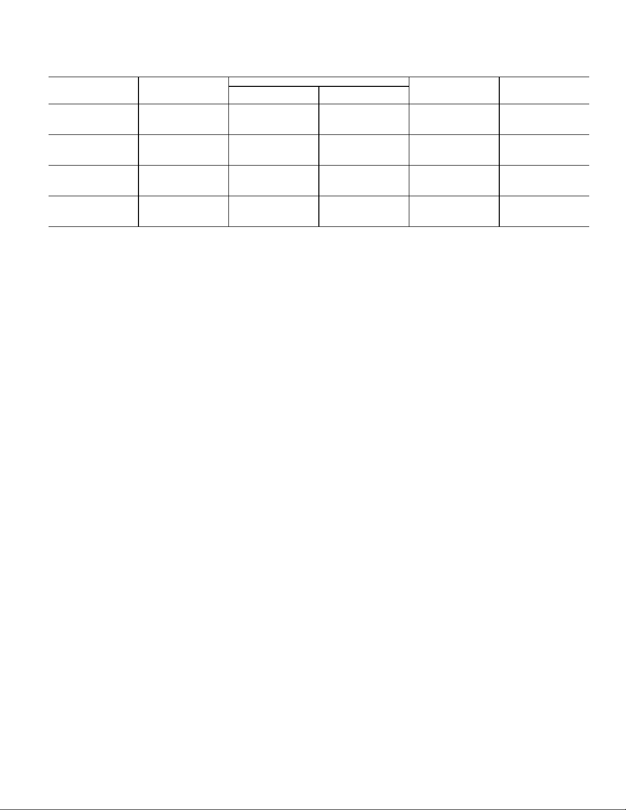
581J*17 BASE UNIT DIMENSIONS
DIMENSIONS
16
Page 17

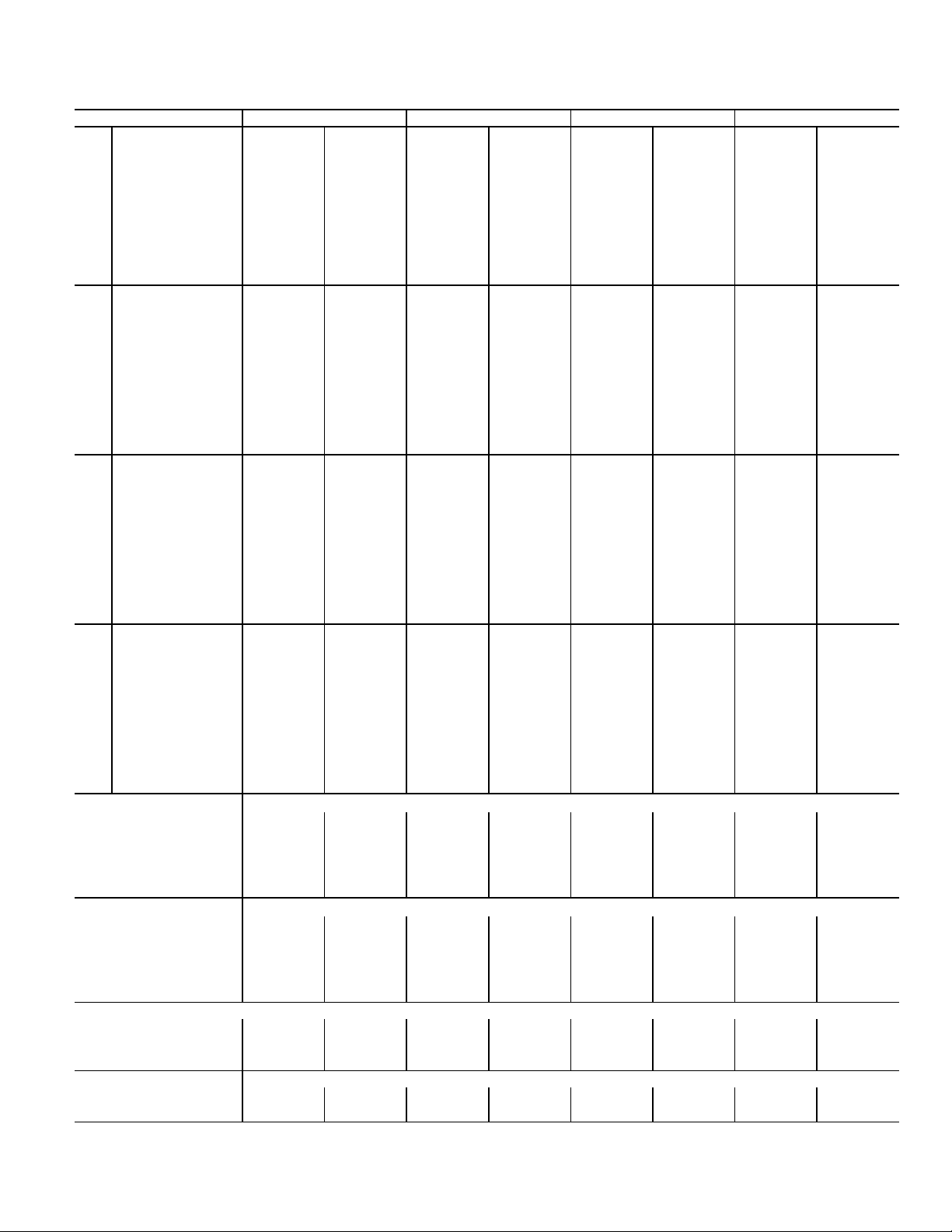
581J*17 BASE UNIT DIMENSIONS (cont)
17
Page 18
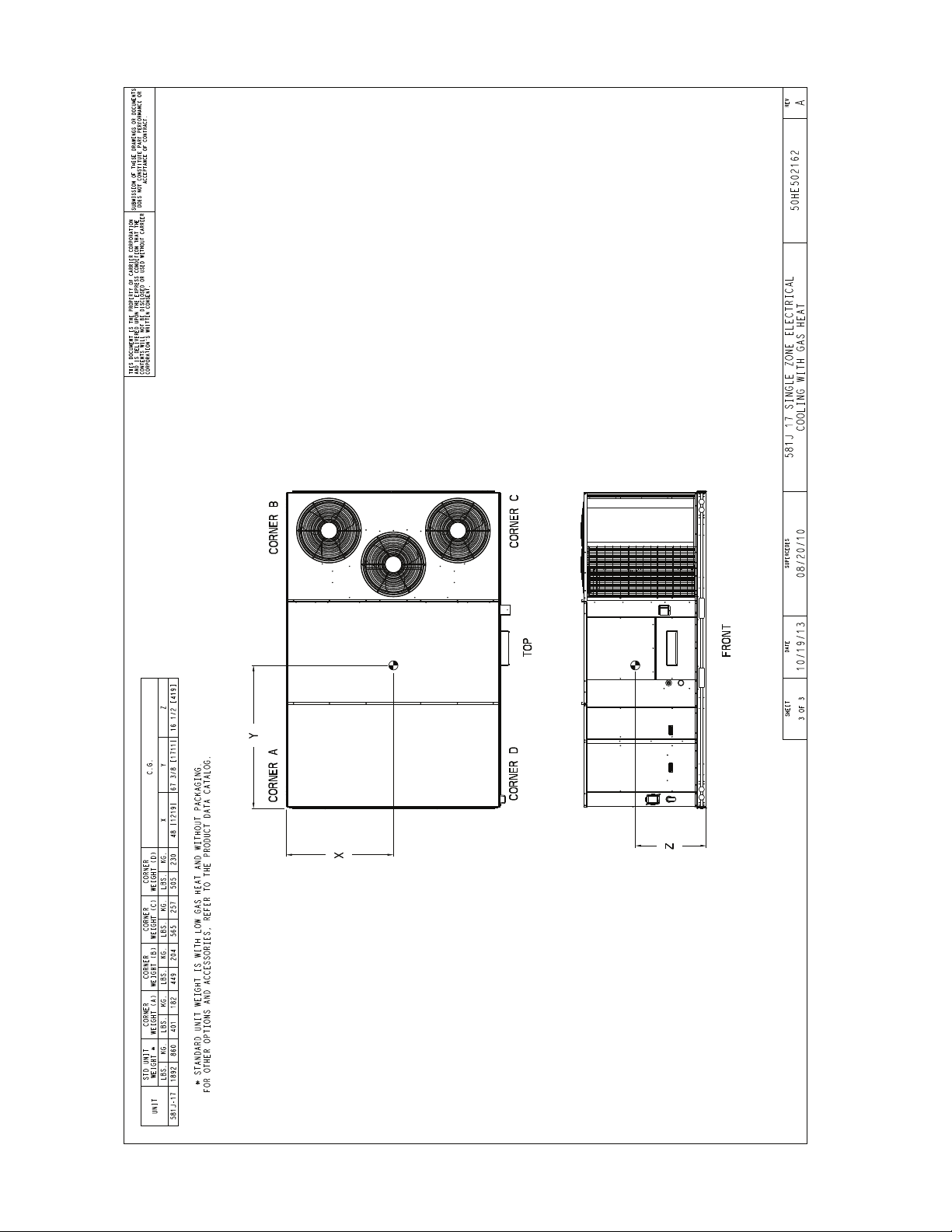
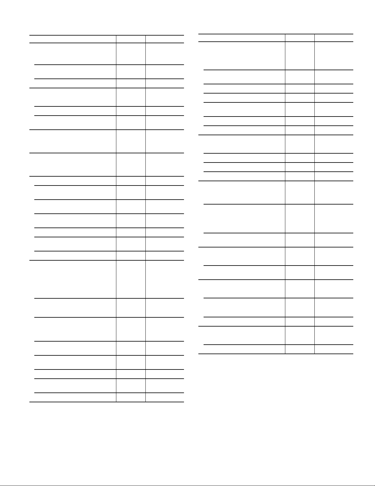
581J*17 CORNER WEIGHTS
DIMENSIONS (cont)
18
Page 19
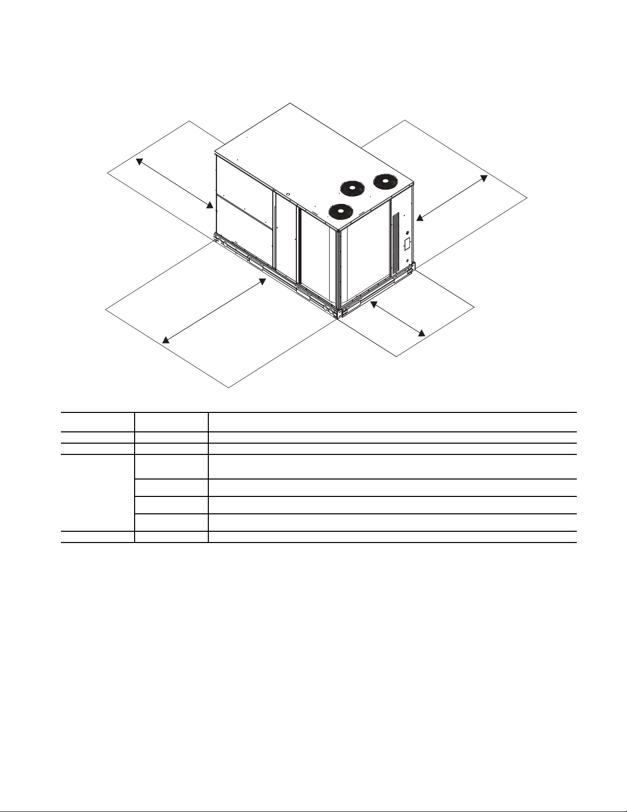
581J*17 SERVICE CLEARANCES
NOTE: Unit is not designed to have overhead obstruction. Contact Application Engineering for guidance on any application planning overhead obstruction or for vertical clearances.
LOCATION
DIMENSION
(in.)
CONDITION
A 36
Recommended clearance for airflow and service.
B 42
Recommended clearance for airflow and service.
C
18
No convenience outlet.
No economizer.
No field-installed disconnect on economizer hood side (factory-installed disconnect installed).
36
Convenience outlet installed.
Vertical surface behind servicer is electrically non-conductive (e.g. wood, fiberglass).
42
Convenience outlet installed.
Vertical surface behind servicer is electrically conductive (e.g. metal, masonry)
96
Economizer and/or Power Exhaust installed.
Check for sources of flue products within 10-ft. of economizer fresh air intake.
D 42
Recommended clearance for service.
C
B
A
D
19
Page 20
DIMENSIONS (cont)
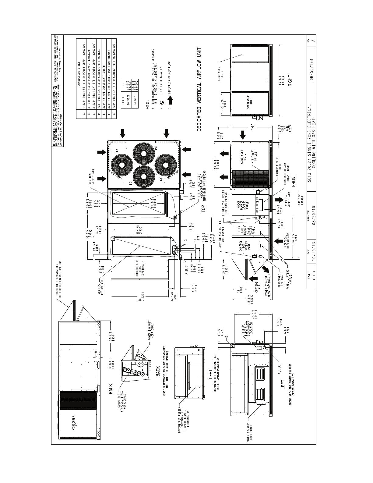
581J*20-24 BASE UNIT DIMENSIONS
20
Page 21
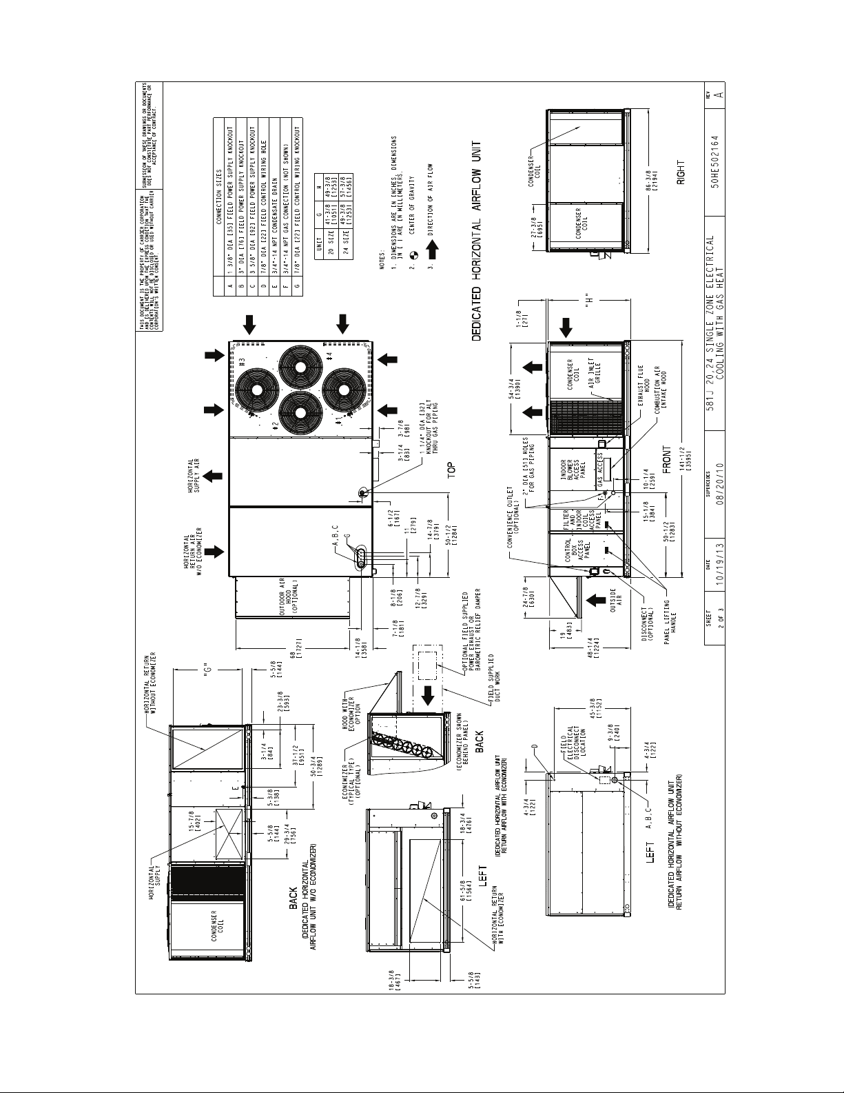
581J*20-24 BASE UNIT DIMENSIONS (cont)
21
Page 22

581J*20-24 CORNER WEIGHTS
DIMENSIONS (cont)
22
Page 23

581J*20-24 SERVICE CLEARANCES
NOTE: Unit is not designed to have overhead obstruction. Contact Application Engineering for guidance on any application planning overhead
obstruction or for vertical clearances.
LOCATION
DIMENSION
(in.)
CONDITION
A 36
Recommended clearance for airflow and service.
B 42
Recommended clearance for airflow and service.
C
18
No convenience outlet.
No economizer.
No field-installed disconnect on economizer hood side (factory-installed disconnect installed).
36
Convenience outlet installed.
Vertical surface behind servicer is electrically non-conductive (e.g. wood, fiberglass).
42
Convenience outlet installed.
Vertical surface behind servicer is electrically conductive (e.g. metal, masonry)
96
Economizer and/or Power Exhaust installed.
Check for sources of flue products within 10-ft. of economizer fresh air intake.
D 42
Recommended clearance for service.
C
B
D
A
23
Page 24

581J*28 BASE UNIT DIMENSIONS
DIMENSIONS (cont)
24
Page 25

581J*28 BASE UNIT DIMENSIONS (cont)
25
Page 26

581J*28 CORNER WEIGHTS
DIMENSIONS (cont)
26
Page 27

581J*28 SERVICE CLEARANCES
NOTE: Unit is not designed to have overhead obstruction. Contact Application Engineering for guidance on any application planning overhead
obstruction or for vertical clearances.
LOCATION
DIMENSION
(in.)
CONDITION
A 36
Recommended clearance for airflow and service.
B 42
Recommended clearance for airflow and service.
C
18
No convenience outlet.
No economizer.
No field-installed disconnect on economizer hood side (factory-installed disconnect installed).
36
Convenience outlet installed.
Vertical surface behind servicer is electrically non-conductive (e.g. wood, fiberglass).
42
Convenience outlet installed.
Vertical surface behind servicer is electrically conductive (e.g. metal, masonry)
96
Economizer and/or Power Exhaust installed.
Check for sources of flue products within 10-ft. of economizer fresh air intake.
D 42
Recommended clearance for service.
C
B
A
D
27
Page 28

581J*17 — ROOF CURB DIMENSIONS
ACCESSORY DIMENSIONS
28
Page 29

581J*20, 24 — ROOF CURB DIMENSIONS
29
Page 30

581J*28 — ROOF CURB DIMENSIONS
ACCESSORY DIMENSIONS (cont)
30
Page 31

PERFORMANCE DATA
581J*17 — 15 TON — COOLING CAPACITIES
581J*17
THC 158.3 158.3 179.2 152.6 152.6 172.9 146.6 146.6 166.1 140.2 140.2 158.8 133.2 133.2 150.8
58
SHC 137.3 158.3 179.2 132.4 152.6 172.9 127.2 146.6 166.1 121.6 140.2 158.8 115.5 133.2 150.8
THC 166.8 166.8 169.0 159.5 159.5 165.6 151.8 151.8 161.9 143.6 143.6 157.9 134.9 134.9 153.4
62
SHC 123.1 146.1 169.0 119.7 142.6 165.6 116.1 139.0 161.9 112.3 135.1 157.9 108.2 130.8 153.4
4500
EAT
Cfm
(wb)
5250
EAT
Cfm
(wb)
6000
EAT
Cfm
(wb)
6750
EAT
Cfm
(wb)
7500
EAT
Cfm
(wb)
LEGEND
——Do Not Operate
Cfm — Cubic Feet Per Minute (Supply Air)
EAT (db) — Entering Air Temperature (Dry Bulb)
EAT (wb)— Entering Air Temperature (Wet Bulb)
SHC — Sensible Heat Capacity (1000 Btuh) Gross
THC — Total Heat Capacity (1000 Btuh) Gross
THC 182.9 182.9 182.9 174.9 174.9 174.9 166.3 166.3 166.3 157.2 157.2 157.2 147.6 147.6 147.6
67
SHC 100.0 123.1 146.1 96.7 119.8 142.8 93.2 116.3 139.4 89.7 112.7 135.7 85.9 108.9 131.9
THC 200.5 200.5 200.5 191.6 191.6 191.6 182.2 182.2 182.2 172.2 172.2 172.2 161.7 161.7 161.7
72
SHC 76.1 99.5 122.8 72.9 96.2 119.5 69.5 92.8 116.1 66.0 89.3 112.5 62.4 85.6 108.8
THC — 215.4 215.4 — 205.8 205.8 — 195.6 195.6 — 184.8 184.8 — 173.6 173.6
76
SHC — 80.2 105.0 — 77.1 101.7 — 73.7 98.2 — 70.2 94.5 — 66.7 90.7
THC 166.7 166.7 188.8 160.6 160.6 181.9 154.0 154.0 174.4 147.0 147.0 166.5 139.5 139.5 157.9
58
SHC 144.6 166.7 188.8 139.3 160.6 181.9 133.6 154.0 174.4 127.6 147.0 166.5 121.0 139.5 157.9
THC 172.0 172.0 185.1 164.3 164.3 181.2 156.3 156.3 177.0 147.8 147.8 172.4 139.6 139.6 164.3
62
SHC 132.5 158.8 185.1 128.9 155.1 181.2 125.0 151.0 177.0 120.9 146.6 172.4 114.9 139.6 164.3
THC 188.3 188.3 188.3 179.7 179.7 179.7 170.7 170.7 170.7 161.0 161.0 161.0 150.9 150.9 150.9
67
SHC 106.1 132.7 159.3 102.8 129.3 155.9 99.3 125.8 152.4 95.6 122.1 148.6 91.7 118.2 144.7
THC 206.1 206.1 206.1 196.7 196.7 196.7 186.7 186.7 186.7 176.2 176.2 176.2 165.3 165.3 165.3
72
SHC 78.8 105.6 132.5 75.5 102.3 129.1 72.1 98.8 125.6 68.5 95.2 121.9 64.8 91.4 118.0
THC — 221.2 221.2 — 211.0 211.0 — 200.3 200.3 — 189.0 189.0 — 177.2 177.2
76
SHC — 83.6 111.7 — 80.3 108.2 — 76.9 104.6 — 73.3 100.9 — 69.7 97.1
THC 173.8 173.8 196.8 167.2 167.2 189.4 160.2 160.2 181.4 152.7 152.7 173.0 144.7 144.7 163.8
58
SHC 150.8 173.8 196.8 145.1 167.2 189.4 139.0 160.2 181.4 132.5 152.7 173.0 125.5 144.7 163.8
THC 176.3 176.3 199.5 168.5 168.5 194.9 160.5 160.5 188.9 152.9 152.9 179.9 144.8 144.8 170.4
62
SHC 140.9 170.2 199.5 136.9 165.9 194.9 132.1 160.5 188.9 125.8 152.9 179.9 119.2 144.8 170.4
THC 192.3 192.3 192.3 183.4 183.4 183.4 173.9 173.9 173.9 164.0 164.0 164.0 153.4 153.4 156.9
67
SHC 112.0 142.0 172.0 108.5 138.5 168.5 104.9 134.9 164.8 101.2 131.1 161.0 97.2 127.1 156.9
THC 210.4 210.4 210.4 200.6 200.6 200.6 190.2 190.2 190.2 179.3 179.3 179.3 167.9 167.9 167.9
72
SHC 81.2 111.4 141.7 77.9 108.0 138.2 74.4 104.5 134.6 70.7 100.8 130.8 67.0 96.9 126.9
THC — 225.6 225.6 — 215.0 215.0 — 203.8 203.8 — 192.1 192.1 — 180.0 180.0
76
SHC — 86.7 117.9 — 83.3 114.5 — 79.9 110.8 — 76.3 107.1 — 72.6 103.2
THC 179.8 179.8 203.7 172.9 172.9 195.8 165.5 165.5 187.4 157.5 157.5 178.4 149.0 149.0 168.8
58
62
67
72
76
58
62
67
72
76
156.0 179.8 203.7 150.0 172.9 195.8 143.5 165.5 187.4 136.7 157.5 178.4 129.3 149.0 168.8
SHC
THC 180.5 180.5 210.7 173.0 173.0 203.6 165.6 165.6 194.9 157.7 157.7 185.5 149.1 149.1 175.5
SHC 147.6 179.2 210.7 142.4 173.0 203.6 136.3 165.6 194.9 129.8 157.7 185.5 122.8 149.1 175.5
THC 195.6 195.6 195.6 186.2 186.2 186.2 176.5 176.5 176.8 166.2 166.2 172.7 155.4 155.4 168.4
SHC 117.5 150.8 184.1 114.0 147.3 180.5 110.4 143.6 176.8 106.5 139.6 172.7 102.4 135.4 168.4
THC 213.8 213.8 213.8 203.6 203.6 203.6 192.9 192.9 192.9 181.6 181.6 181.6 169.9 169.9 169.9
SHC 83.5 117.0 150.5 80.1 113.5 147.0 76.5 109.9 143.3 72.8 106.1 139.4 69.1 102.3 135.5
THC — 229.1 229.1 — 218.1 218.1 — 206.6 206.6 — 194.6 194.6 — 182.1 182.1
SHC — 89.6 124.0 — 86.2 120.5 — 82.7 116.8 — 79.0 113.0 — 75.2 109.0
THC 185.1 185.1 209.6 177.7 177.7 201.3 170.0 170.0 192.5 161.6 161.6 183.0 152.8 152.8 173.0
SHC 160.6 185.1 209.6 154.2 177.7 201.3 147.5 170.0 192.5 140.2 161.6 183.0 132.5 152.8 173.0
THC 185.2 185.2 218.0 177.9 177.9 209.3 170.1 170.1 200.2 161.8 161.8 190.4 152.9 152.9 179.9
SHC 152.5 185.2 218.0 146.4 177.9 209.3 140.0 170.1 200.2 133.2 161.8 190.4 125.8 152.9 179.9
THC 198.1 198.1 198.1 188.6 188.6 192.1 178.6 178.6 188.1 168.1 168.1 183.8 157.2 157.2 179.1
SHC 122.8 159.3 195.9 119.2 155.7 192.1 115.5 151.8 188.1 111.5 147.7 183.8 107.3 143.2 179.1
THC 216.6 216.6 216.6 206.1 206.1 206.1 195.1 195.1 195.1 183.5 183.5 183.5 171.6 171.6 171.6
SHC 85.6 122.3 159.0 82.2 118.8 155.5 78.6 115.2 151.7 74.9 111.3 147.8 71.1 107.4 143.8
THC — 231.9 231.9 — 220.7 220.7 — 208.9 208.9 — 196.5 196.5 — 183.8 183.8
SHC — 92.4 129.9 — 88.9 126.3 — 85.4 122.6 — 81.6 118.7 — 77.8 114.6
85 95 105 115 125
EAT (db) EAT (db) EAT (db) EAT (db) EAT (db)
75 80 85 75 80 85 75 80 85 75 80 85 75 80 85
AMBIENT TEMPERATURE (F)
31
Page 32

PERFORMANCE DATA (cont)
581J*20 — 17.5 TON — COOLING CAPACITIES
581J20
THC 185.1 185.1 209.2 178.7 178.7 201.9 171.8 171.8 194.1 164.5 164.5 185.8 156.7 156.7 177.0
58
SHC 161.1 185.1 209.2 155.4 178.7 201.9 149.4 171.8 194.1 143.1 164.5 185.8 136.3 156.7 177.0
THC 193.8 193.8 199.5 185.6 185.6 195.4 176.9 176.9 191.1 167.7 167.7 186.4 158.2 158.2 181.1
62
SHC 145.6 172.6 199.5 141.7 168.6 195.4 137.6 164.4 191.1 133.2 159.8 186.4 128.3 154.7 181.1
5250
EAT
Cfm
(wb)
6125
EAT
Cfm
(wb)
7000
EAT
Cfm
(wb)
7875
EAT
Cfm
(wb)
8750
EAT
Cfm
(wb)
LEGEND
——Do Not Operate
Cfm — Cubic Feet Per Minute (Supply Air)
EAT (db) — Entering Air Temperature (Dry Bulb)
EAT (wb)— Entering Air Temperature (Wet Bulb)
SHC — Sensible Heat Capacity (1000 Btuh) Gross
THC — Total Heat Capacity (1000 Btuh) Gross
THC 212.2 212.2 212.2 203.3 203.3 203.3 193.8 193.8 193.8 183.8 183.8 183.8 173.1 173.1 173.1
67
SHC 119.0 146.0 173.1 115.3 142.3 169.4 111.4 138.4 165.4 107.3 134.3 161.3 103.0 130.0 157.0
THC 232.3 232.3 232.3 222.7 222.7 222.7 212.4 212.4 212.4 201.6 201.6 201.6 190.1 190.1 190.1
72
SHC 91.5 118.8 146.2 87.9 115.2 142.5 84.1 111.4 138.7 80.2 107.4 134.6 76.0 103.2 130.4
THC — 249.5 249.5 — 239.2 239.2 — 228.2 228.2 — 216.6 216.6 — 204.3 204.3
76
SHC — 96.7 125.3 — 93.2 121.7 — 89.5 117.9 — 85.6 113.8 — 81.5 109.5
THC 194.7 194.7 220.0 187.8 187.8 212.2 180.4 180.4 203.8 172.5 172.5 194.9 164.1 164.1 185.5
58
SHC 169.4 194.7 220.0 163.3 187.8 212.2 156.9 180.4 203.8 150.1 172.5 194.9 142.8 164.1 185.5
THC 199.6 199.6 218.0 191.1 191.1 213.5 182.1 182.1 208.4 173.0 173.0 201.2 164.3 164.3 192.8
62
SHC 156.5 187.2 218.0 152.3 182.9 213.5 147.7 178.0 208.4 141.8 171.5 201.2 135.8 164.3 192.8
THC 218.0 218.0 218.0 208.7 208.7 208.7 198.7 198.7 198.7 188.2 188.2 188.2 177.1 177.1 177.1
67
SHC 126.2 157.4 188.6 122.4 153.6 184.7 118.4 149.6 180.7 114.3 145.4 176.5 109.9 141.0 172.1
THC 238.5 238.5 238.5 228.4 228.4 228.4 217.7 217.7 217.7 206.3 206.3 206.3 194.3 194.3 194.3
72
SHC 94.7 126.1 157.5 91.0 122.4 153.8 87.2 118.5 149.8 83.1 114.4 145.7 78.9 110.1 141.4
THC — 255.9 255.9 — 245.1 245.1 — 233.6 233.6 — 221.4 221.4 — 208.5 208.5
76
SHC — 100.7 133.3 — 97.1 129.6 — 93.3 125.6 — 89.3 121.5 — 85.1 117.1
THC 202.7 202.7 229.1 195.4 195.4 220.8 187.5 187.5 211.9 179.2 179.2 202.5 170.3 170.3 192.4
58
SHC 176.4 202.7 229.1 170.0 195.4 220.8 163.1 187.5 211.9 155.9 179.2 202.5 148.1 170.3 192.4
THC 204.6 204.6 234.4 196.0 196.0 228.0 187.7 187.7 220.3 179.3 179.3 210.5 170.4 170.4 200.0
62
SHC 166.0 200.2 234.4 160.8 194.4 228.0 155.1 187.7 220.3 148.2 179.3 210.5 140.8 170.4 200.0
THC 222.5 222.5 222.5 212.8 212.8 212.8 202.4 202.4 202.4 191.5 191.5 191.5 180.0 180.0 186.4
67
SHC 133.0 168.2 203.4 129.2 164.3 199.5 125.1 160.3 195.4 120.9 156.0 191.0 116.4 151.4 186.4
THC 243.3 243.3 243.3 232.7 232.7 232.7 221.6 221.6 221.6 209.9 209.9 209.9 197.4 197.4 197.4
72
SHC 97.5 132.9 168.3 93.8 129.2 164.5 89.9 125.2 160.5 85.8 121.1 156.3 81.6 116.7 151.9
THC — 260.8 260.8 — 249.6 249.6 — 237.7 237.7 — 225.1 225.1 — 211.7 211.7
76
SHC — 104.4 140.8 — 100.7 137.0 — 96.9 133.0 — 92.8 128.8 — 88.5 124.4
THC 209.6 209.6 236.8 201.8 201.8 228.1 193.6 193.6 218.8 184.8 184.8 208.9 175.5 175.5 198.3
58
SHC 182.3 209.6 236.8 175.6 201.8 228.1 168.4 193.6 218.8 160.8 184.8 208.9 152.7 175.5 198.3
THC 209.8 209.8 246.2 202.0 202.0 237.1 193.8 193.8 227.4 185.0 185.0 217.1 175.6 175.6 206.1
62
SHC 173.4 209.8 246.2 167.0 202.0 237.1 160.1 193.8 227.4 152.9 185.0 217.1 145.1 175.6 206.1
THC 226.1 226.1 226.1 216.0 216.0 216.0 205.4 205.4 209.4 194.2 194.2 204.8 182.4 182.4 199.9
67
SHC 139.6 178.6 217.7 135.6 174.7 213.7 131.5 170.5 209.4 127.1 166.0 204.8 122.5 161.2 199.9
THC 247.0 247.0 247.0 236.2 236.2 236.2 224.7 224.7 224.7 212.7 212.7 212.7 199.9 199.9 199.9
72
SHC 100.2 139.5 178.8 96.5 135.7 174.9 92.5 131.7 170.9 88.4 127.5 166.6 84.1 123.1 162.1
THC — 264.7 264.7 — 253.1 253.1 — 240.9 240.9 — 227.9 227.9 — — —
76
SHC — 107.9 148.1 — 104.2 144.3 — 100.2 140.2 — 96.1 135.9 — — —
THC 215.4 215.4 243.4 207.3 207.3 234.3 198.7 198.7 224.6 189.6 189.6 214.2 179.9 179.9 203.2
58
SHC 187.4 215.4 243.4 180.3 207.3 234.3 172.9 198.7 224.6 164.9 189.6 214.2 156.5 179.9 203.2
THC 215.5 215.5 253.0 207.5 207.5 243.5 198.9 198.9 233.4 189.7 189.7 222.7 180.0 180.0 211.2
62
SHC 178.1 215.5 253.0 171.5 207.5 243.5 164.4 198.9 233.4 156.8 189.7 222.7 148.8 180.0 211.2
THC 228.9 228.9 231.5 218.7 218.7 227.3 207.8 207.8 222.8 196.4 196.4 217.9 184.5 184.5 212.6
67
SHC 145.8 188.6 231.5 141.8 184.5 227.3 137.5 180.1 222.8 133.0 175.5 217.9 128.2 170.4 212.6
THC 250.1 250.1 250.1 239.0 239.0 239.0 227.3 227.3 227.3 214.9 214.9 214.9 201.8 201.8 201.8
72
SHC 102.8 145.8 188.9 99.0 142.0 185.0 95.0 137.9 180.9 90.8 133.7 176.5 86.4 129.2 172.0
THC — 267.8 267.8 — 256.0 256.0 — 243.5 243.5 — 230.2 230.2 — — —
76
SHC — 111.2 155.2 — 107.4 151.3 — 103.5 147.1 — 99.3 142.8 — — —
85 95 105 115 125
EAT (db) EAT (db) EAT (db) EAT (db) EAT (db)
75 80 85 75 80 85 75 80 85 75 80 85 75 80 85
AMBIENT TEMPERATURE (F)
32
Page 33

581J*D24 — 20 TON — COOLING CAPACITIES
581J24
THC 214.4 214.4 242.5 207.0 207.0 234.2 199.0 199.0 225.1 190.2 190.2 215.2 180.6 180.6 204.3
58
SHC 186.3 214.4 242.5 179.9 207.0 234.2 173.0 199.0 225.1 165.3 190.2 215.2 157.0 180.6 204.3
THC 226.8 226.8 227.7 217.3 217.3 223.0 206.9 206.9 218.0 195.8 195.8 212.5 183.7 183.7 206.4
62
SHC 167.0 197.3 227.7 162.4 192.7 223.0 157.6 187.8 218.0 152.3 182.4 212.5 146.6 176.5 206.4
6000
EAT
Cfm
(wb)
7000
EAT
Cfm
(wb)
8000
EAT
Cfm
(wb)
9000
EAT
Cfm
(wb)
10000
LEGEND
——Do Not Operate
Cfm — Cubic Feet Per Minute (Supply Air)
EAT (db) — Entering Air Temperature (Dry Bulb)
EAT (wb)— Entering Air Temperature (Wet Bulb)
SHC — Sensible Heat Capacity (1000 Btuh) Gross
THC — Total Heat Capacity (1000 Btuh) Gross
Cfm
EAT
(wb)
THC 248.4 248.4 248.4 237.9 237.9 237.9 226.6 226.6 226.6 214.3 214.3 214.3 201.0 201.0 201.0
67
SHC 136.5 167.1 197.6 132.2 162.7 193.2 127.5 158.0 188.4 122.5 152.9 183.4 117.2 147.6 178.0
THC 271.9 271.9 271.9 260.3 260.3 260.3 247.9 247.9 247.9 234.5 234.5 234.5 220.1 220.1 220.1
72
SHC 105.1 136.0 167.0 100.8 131.7 162.5 96.3 127.1 157.9 91.4 122.1 152.9 86.3 116.9 147.6
THC — 291.7 291.7 — 279.2 279.2 — 265.7 265.7 — 251.3 251.3 — 235.8 235.8
76
SHC — 110.7 143.7 — 106.5 139.5 — 102.0 134.7 — 97.2 129.7 — 92.1 124.3
THC 225.8 225.8 255.3 217.8 217.8 246.3 209.1 209.1 236.5 199.6 199.6 225.7 189.2 189.2 214.0
58
SHC 196.2 225.8 255.3 189.3 217.8 246.3 181.7 209.1 236.5 173.4 199.6 225.7 164.4 189.2 214.0
THC 233.9 233.9 248.8 223.8 223.8 243.8 213.1 213.1 238.2 201.4 201.4 231.8 190.0 190.0 221.5
62
SHC 179.4 214.1 248.8 174.6 209.2 243.8 169.4 203.8 238.2 163.7 197.8 231.8 155.9 188.7 221.5
THC 255.7 255.7 255.7 244.6 244.6 244.6 232.6 232.6 232.6 219.6 219.6 219.6 205.7 205.7 205.7
67
SHC 144.7 179.7 214.8 140.2 175.2 210.2 135.4 170.4 205.4 130.3 165.2 200.2 124.9 159.8 194.7
THC 279.4 279.4 279.4 267.3 267.3 267.3 254.1 254.1 254.1 240.1 240.1 240.1 224.9 224.9 224.9
72
SHC 108.7 144.1 179.6 104.3 139.7 175.1 99.6 135.0 170.3 94.7 129.9 165.1 89.5 124.6 159.7
THC — 299.4 299.4 — 286.2 286.2 — 272.1 272.1 — 256.9 256.9 — 240.7 240.7
76
SHC — 115.3 152.9 — 110.9 148.2 — 106.3 143.3 — 101.3 138.0 — 96.1 132.6
THC 235.3 235.3 266.2 226.8 226.8 256.5 217.5 217.5 246.0 207.4 207.4 234.5 196.3 196.3 222.0
58
SHC 204.5 235.3 266.2 197.1 226.8 256.5 189.0 217.5 246.0 180.2 207.4 234.5 170.6 196.3 222.0
THC 239.7 239.7 268.1 229.4 229.4 262.0 219.0 219.0 253.3 208.3 208.3 241.9 196.7 196.7 231.0
62
SHC 190.7 229.4 268.1 185.4 223.7 262.0 178.6 215.9 253.3 170.4 206.2 241.9 162.3 196.7 231.0
THC 261.3 261.3 261.3 249.6 249.6 249.6 237.1 237.1 237.1 223.6 223.6 223.6 209.2 209.2 210.6
67
SHC 152.3 191.8 231.2 147.7 187.1 226.6 142.9 182.2 221.6 137.7 177.0 216.3 132.2 171.4 210.6
THC 285.3 285.3 285.3 272.5 272.5 272.5 258.9 258.9 258.9 244.2 244.2 244.2 228.6 228.6 228.6
72
SHC 111.9 151.7 191.5 107.5 147.2 186.9 102.7 142.4 182.0 97.7 137.2 176.7 92.4 131.8 171.2
THC — 305.4 305.4 — 291.6 291.6 — 276.8 276.8 — 261.2 261.2 — 244.4 244.4
76
SHC — 119.4 161.0 — 114.9 156.2 — 110.1 151.2 — 105.1 146.0 — 99.8 140.4
THC 243.5 243.5 275.4 234.5 234.5 265.2 224.6 224.6 254.0 213.9 213.9 241.9 202.3 202.3 228.8
58
62
67
72
76
58
62
67
72
76
211.6 243.5 275.4 203.8 234.5 265.2 195.2 224.6 254.0 185.9 213.9 241.9 175.8 202.3 228.8
SHC
THC 245.4 245.4 282.9 235.4 235.4 274.6 225.0 225.0 264.3 214.4 214.4 251.7 202.5 202.5 237.8
SHC 199.7 241.3 282.9 193.2 233.9 274.6 185.6 224.9 264.3 176.8 214.3 251.7 167.1 202.5 237.8
THC 265.6 265.6 265.6 253.6 253.6 253.6 240.7 240.7 240.7 226.8 226.8 231.8 212 212.0 225.8
SHC 159.6 203.3 247.1 154.9 198.6 242.3 150.0 193.6 237.3 144.7 188.3 231.8 139.0 182.4 225.8
THC 289.9 289.9 289.9 276.7 276.7 276.7 262.6 262.6 262.6 247.5 247.5 247.5 231.4 231.4 231.4
SHC 114.9 159.0 203.0 110.4 154.4 198.3 105.6 149.5 193.3 100.5 144.2 188.0 95.2 138.7 182.3
THC — 310.1 310.1 — 295.8 295.8 — 280.6 280.6 — 264.4 264.4 — 247.3 247.3
SHC — 123.2 168.9 — 118.6 164.1 — 113.8 159.0 — 108.7 153.6 — 103.4 147.9
THC 250.4 250.4 283.2 240.9 240.9 272.5 230.7 230.7 260.9 219.5 219.5 248.2 207.3 207.3 234.5
SHC 217.7 250.4 283.2 209.4 240.9 272.5 200.5 230.7 260.9 190.7 219.5 248.2 180.2 207.3 234.5
THC 250.8 250.8 294.6 241.1 241.1 283.3 231.1 231.1 271.4 219.6 219.6 258.0 207.5 207.5 243.7
SHC 207.0 250.8 294.6 199.0 241.1 283.3 190.7 231.1 271.4 181.2 219.6 258.0 171.2 207.5 243.7
THC 269.2 269.2 269.2 256.8 256.8 257.6 243.5 243.5 252.3 229.4 229.4 246.4 214.3 214.3 240.0
SHC 166.6 214.5 262.5 161.9 209.7 257.6 156.8 204.5 252.3 151.3 198.9 246.4 145.5 192.8 240.0
THC 293.7 293.7 293.7 280.1 280.1 280.1 265.6 265.6 265.6 250.2 250.2 250.2 233.7 233.7 233.7
SHC 117.8 166.0 214.2 113.2 161.3 209.3 108.3 156.3 204.3 103.2 151.0 198.8 97.8 145.4 193.1
THC — 313.9 313.9 — 299.3 299.3 — 283.7 283.7 — 267.1 267.1 — 249.6 249.6
SHC — 126.8 176.5 — 122.2 171.6 — 117.3 166.5 — 112.1 161.0 — 106.7 155.1
85 95 105 115 125
EAT (db) EAT (db) EAT (db) EAT (db) EAT (db)
75 80 85 75 80 85 75 80 85 75 80 85 75 80 85
AMBIENT TEMPERATURE (F)
33
Page 34

PERFORMANCE DATA (CONT)
581J*D28 — 25 TON — COOLING CAPACITIES
AMBIENT TEMPERATURE (F)
581J28
THC 264.4 264.4 298.9 254.6 254.6 287.9 244.1 244.1 276.0 232.7 232.7 263.1 220.3 220.3 249.1
58
SHC 229.9 264.4 298.9 221.4 254.6 287.9 212.2 244.1 276.0 202.3 232.7 263.1 191.5 220.3 249.1
THC 278.7 278.7 282.4 266.3 266.3 276.4 252.8 252.8 269.8 238.5 238.5 262.4 223.9 223.9 251.3
62
SHC 206.8 244.6 282.4 200.9 238.7 276.4 194.6 232.2 269.8 187.7 225.0 262.4 178.7 215.0 251.3
7500
EAT
Cfm
(wb)
8750
EAT
Cfm
(wb)
10000
11250
12500
LEGEND
——Do Not Operate
Cfm — Cubic Feet Per Minute (Supply Air)
EAT (db) — Entering Air Temperature (Dry Bulb)
EAT (wb) — Entering Air Temperature (Wet Bulb)
SHC — Sensible Heat Capacity (1000 Btuh) Gross
THC — Total Heat Capacity (1000 Btuh) Gross
Cfm
Cfm
Cfm
EAT
(wb)
EAT
(wb)
EAT
(wb)
THC 305.3 305.3 305.3 291.9 291.9 291.9 277.3 277.3 277.3 261.5 261.5 261.5 244.5 244.5 244.5
67
SHC 169.0 207.0 245.0 163.4 201.4 239.4 157.4 195.3 233.3 151.0 188.9 226.8 144.2 182.1 219.9
THC 334.0 334.0 334.0 319.4 319.4 319.4 303.6 303.6 303.6 286.5 286.5 286.5 268.1 268.1 268.1
72
SHC 129.9 168.5 207.1 124.5 163.0 201.5 118.7 157.1 195.5 112.5 150.8 189.2 106.0 144.2 182.3
THC — 358.2 358.2 — 342.4 342.4 — 325.4 325.4 — 307.1 307.1 — 287.4 287.4
76
SHC — 137.0 178.2 — 131.7 172.9 — 126.0 166.9 — 119.9 160.4 — 113.4 153.4
THC 278.2 278.2 314.5 267.8 267.8 302.8 256.5 256.5 289.9 244.2 244.2 276.1 230.8 230.8 261.0
58
SHC 241.9 278.2 314.5 232.8 267.8 302.8 223.0 256.5 289.9 212.3 244.2 276.1 200.7 230.8 261.0
THC 287.2 287.2 308.3 274.3 274.3 301.5 260.8 260.8 291.7 247.0 247.0 280.9 232.0 232.0 269.1
62
SHC 222.1 265.2 308.3 215.7 258.6 301.5 207.7 249.7 291.7 199.0 240.0 280.9 189.7 229.4 269.1
THC 314.0 314.0 314.0 299.8 299.8 299.8 284.4 284.4 284.4 267.8 267.8 267.8 250.0 250.0 250.0
67
SHC 179.1 222.7 266.4 173.3 216.9 260.6 167.2 210.8 254.3 160.7 204.2 247.7 153.7 197.2 240.6
THC 343.0 343.0 343.0 327.7 327.7 327.7 311.1 311.1 311.1 293.1 293.1 293.1 273.8 273.8 273.8
72
SHC 134.3 178.5 222.6 128.8 172.9 216.9 122.9 166.9 210.8 116.6 160.4 204.3 109.9 153.6 197.3
THC — 367.3 367.3 — 350.8 350.8 — 333.0 333.0 — 313.8 313.8 — 293.2 293.2
76
SHC — 142.6 189.4 — 137.1 183.5 — 131.2 177.3 — 125.0 170.7 — 118.4 163.7
THC 289.7 289.7 327.5 278.7 278.7 315.0 266.6 266.6 301.4 253.6 253.6 286.7 239.4 239.4 270.7
58
SHC 251.9 289.7 327.5 242.3 278.7 315.0 231.8 266.6 301.4 220.5 253.6 286.7 208.2 239.4 270.7
THC 294.6 294.6 329.6 282.2 282.2 319.7 268.7 268.7 309.1 254.1 254.1 298.4 239.7 239.7 281.4
62
SHC 234.7 282.1 329.6 226.8 273.3 319.7 218.4 263.7 309.1 209.7 254.1 298.4 197.9 239.7 281.4
THC 320.6 320.6 320.6 305.9 305.9 305.9 289.9 289.9 289.9 272.7 272.7 272.7 254.3 254.3 260.3
67
SHC 188.6 237.7 286.8 182.7 231.8 280.9 176.5 225.5 274.5 169.8 218.8 267.7 162.8 211.5 260.3
THC 350.0 350.0 350.0 334.0 334.0 334.0 316.8 316.8 316.8 298.2 298.2 298.2 278.3 278.3 278.3
72
SHC 138.4 187.9 237.5 132.8 182.2 231.7 126.8 176.1 225.5 120.4 169.6 218.8 113.6 162.6 211.7
THC — 374.4 374.4 — 357.3 357.3 — 338.7 338.7 — 318.9 318.9 — 297.5 297.5
76
SHC — 147.7 199.5 — 142.1 193.7 — 136.1 187.4 — 129.7 180.6 — 123.0 173.5
THC 299.4 299.4 338.4 287.8 287.8 325.4 275.2 275.2 311.1 261.4 261.4 295.6 246.6 246.6 278.8
58
62
67
72
76
58
62
67
72
76
260.3 299.4 338.4 250.2 287.8 325.4 239.2 275.2 311.1 227.3 261.4 295.6 214.4 246.6 278.8
SHC
THC 302.2 302.2 346.0 289.3 289.3 335.7 275.5 275.5 323.5 262.1 262.1 307.7 246.8 246.8 289.8
SHC 244.8 295.4 346.0 236.7 286.2 335.7 227.5 275.5 323.5 216.4 262.1 307.7 203.8 246.8 289.8
THC 325.9 325.9 325.9 310.7 310.7 310.7 294.2 294.2 294.2 276.6 276.6 286.7 257.7 257.7 278.9
SHC 197.6 252.1 306.5 191.7 246.1 300.4 185.3 239.6 293.9 178.5 232.6 286.7 171.2 225.1 278.9
THC 355.5 355.5 355.5 339.1 339.1 339.1 321.3 321.3 321.3 302.2 302.2 302.2 281.8 281.8 281.8
SHC 142.1 197.0 251.8 136.4 191.2 245.9 130.4 185.0 239.6 123.9 178.3 232.8 117.1 171.3 225.5
THC — 380.0 380.0 — 362.4 362.4 — 343.3 343.3 — 322.8 322.8 — 300.9 300.9
SHC — 152.4 209.4 — 146.8 203.4 — 140.7 197.0 — 134.2 190.2 — 127.3 182.8
THC 307.7 307.7 347.9 295.7 295.7 334.2 282.5 282.5 319.3 268.2 268.2 303.2 252.7 252.7 285.7
SHC 267.6 307.7 347.9 257.1 295.7 334.2 245.6 282.5 319.3 233.2 268.2 303.2 219.7 252.7 285.7
THC 308.4 308.4 362.2 295.9 295.9 347.4 283.1 283.1 332.4 268.4 268.4 315.2 252.8 252.8 296.9
SHC 254.6 308.4 362.2 244.4 295.9 347.4 233.8 283.1 332.4 221.7 268.4 315.2 208.8 252.8 296.9
THC 330.2 330.2 330.2 314.6 314.6 319.2 297.8 297.8 312.3 279.8 279.8 304.7 260.6 260.6 295.9
SHC 206.3 265.9 325.5 200.3 259.7 319.2 193.8 253.1 312.3 186.7 245.7 304.7 179.0 237.4 295.9
THC 360.1 360.1 360.1 343.2 343.2 343.2 325.0 325.0 325.0 305.4 305.4 305.4 284.6 284.6 284.6
SHC 145.7 205.7 265.7 139.9 199.8 259.7 133.8 193.5 253.3 127.3 186.8 246.3 120.4 179.7 238.9
THC — 384.6 384.6 — 366.5 366.5 — 346.9 346.9 — 325.9 325.9 — 303.5 303.5
SHC — 157.0 218.9 — 151.2 212.9 — 145.1 206.3 — 138.5 199.3 — 131.5 191.7
85 95 105 115 125
EAT (db) EAT (db) EAT (db) EAT (db) EAT (db)
75 80 85 75 80 85 75 80 85 75 80 85 75 80 85
34
Page 35

TEMP (F)
AIR ENT
CONDENSER
(Edb)
TC
75
85
95
105
115
125
TEMP (F)
AIR ENT
CONDENSER
(Edb)
80
75
70
60
50
40
SHC
kW
TC
SHC
kW
TC
SHC
kW
TC
SHC
kW
TC
SHC
kW
TC
SHC
kW
TC
SHC
kW
TC
SHC
kW
TC
SHC
kW
TC
SHC
kW
TC
SHC
kW
TC
SHC
kW
LEGEND
Edb — Entering Dry Bulb
Ewb — Entering Wet Bulb
kW — Kilowatts
SHC — Sensible Heat Capacity
TC — Total Capacity
581J*17 COOLING CAPACITIES, SUBCOOLING MODE
AIR ENTERING EVAPORATOR - CFM
4,500 6,000 7,500
Air Entering Evaporator - Ewb (F)
72 67 62 72 67 62 72 67 62
202.90 184.60 166.20 213.70 194.60 175.40 222.30 202.50 182.70
91.90 112.40 132.90 106.10 126.40 146.80 117.50 137.70 158.00
10.19 10.12 9.78 10.51 10.19 9.95 10.61 10.36 10.12
189.80 171.80 153.80 201.00 182.20 163.30 209.90 190.40 170.80
75.90 101.00 126.20 91.20 116.30 141.30 103.40 128.40 153.50
11.57 11.49 11.15 11.88 11.56 11.32 11.98 11.73 11.49
176.70 159.10 141.40 188.30 169.70 151.20 197.50 178.20 159.00
59.80 89.70 119.60 76.20 106.10 135.90 89.40 119.20 149.00
12.87 12.81 12.47 13.20 12.88 12.64 13.30 13.05 12.81
163.60 146.30 129.00 175.60 157.30 139.10 185.10 166.10 147.10
43.80 78.40 112.90 61.30 95.90 130.40 75.30 109.90 144.40
14.05 14.00 13.65 14.39 14.07 13.82 14.40 14.24 14.00
150.50 133.50 116.50 162.90 144.90 127.00 172.70 154.00 135.30
27.70 67.00 106.30 46.40 85.70 125.00 61.30 100.60 133.40
15.44 15.36 15.02 15.75 15.43 15.19 15.85 15.60 15.36
137.40 120.80 104.10 150.20 132.50 114.90 160.30 141.90 123.50
11.70 55.70 99.60 31.40 75.50 112.90 47.30 91.30 123.00
16.77 16.71 16.37 17.10 16.78 16.54 17.20 16.95 16.71
581J*17 COOLING CAPACITIES, HOT GAS REHEAT MODE
AIR ENTERING EVAPORATOR - Ewb (F)
75 Dry Bulb
62.5 Wet Bulb
(50% Relative)
Air Entering Evaporator - Cfm
4,500 6,000 7,500 4,500 6,000 7,500 4,500 6,000 7,500
64.50 71.00 73.30 68.40 74.50 77.30 71.20 79.70 80.60
12.60 24.90 36.80 6.80 13.70 23.90 -0.80 5.50 13.80
10.10 10.26 10.42 10.18 10.40 10.56 10.33 10.47 10.67
66.60 73.10 75.60 70.50 76.60 79.50 73.20 80.80 82.90
14.30 26.70 38.50 8.10 14.90 25.70 0.70 7.00 15.00
10.05 10.22 10.36 10.14 10.36 10.52 10.28 10.43 10.62
68.70 75.10 77.40 72.50 78.60 81.40 75.20 82.80 84.90
15.40 27.80 40.00 9.50 16.20 26.80 2.10 8.40 16.30
10.00 10.18 10.33 10.10 10.31 10.47 10.23 10.40 10.58
72.80 79.30 81.60 76.70 82.80 85.70 79.40 86.90 88.80
19.00 31.10 43.20 12.70 19.90 30.10 5.30 11.60 20.00
9.92 10.09 10.24 10.01 10.22 10.37 10.14 10.31 10.49
76.80 83.40 85.70 80.80 86.90 89.70 83.50 90.90 92.80
21.70 34.20 46.20 15.80 22.70 33.20 8.40 14.70 22.80
9.83 10.00 10.15 9.92 10.13 10.29 10.05 10.21 10.39
80.90 87.30 89.60 84.90 90.80 93.60 87.40 94.80 96.70
24.90 37.10 49.30 19.00 26.00 36.10 11.60 17.90 26.20
9.74 9.91 10.06 9.83 10.04 10.20 9.96 10.12 10.30
75 Dry Bulb
64 Wet Bulb
(56% Relative)
75 Dry Bulb
65.3 Wet Bulb
(60% Relative)
35
Page 36

PERFORMANCE DATA (CONT)
581J*20 COOLING CAPACITIES, SUBCOOLING MODE
TEMP (F)
AIR ENT
CONDENSER
75
85
95
105
115
125
TEMP (F)
AIR ENT
CONDENSER
80
75
70
60
50
40
(Edb)
(Edb)
TC
SHC
kW
TC
SHC
kW
TC
SHC
kW
TC
SHC
kW
TC
SHC
kW
TC
SHC
kW
TC
SHC
kW
TC
SHC
kW
TC
SHC
kW
TC
SHC
kW
TC
SHC
kW
TC
SHC
kW
AIR ENTERING EVAPORATOR - CFM
5250 7000 8750
Air Entering Evaporator - Ewb (F)
72 67 62 72 67 62 72 67 62
232.00 211.30 190.60 242.40 221.00 199.70 250.70 228.90 207.00
110.90 133.70 156.40 127.60 150.30 173.00 141.10 163.70 186.40
12.45 12.16 11.81 12.74 12.41 12.02 12.93 12.51 12.18
215.90 195.70 175.50 226.00 205.20 184.40 234.20 212.80 191.50
90.60 118.80 147.00 108.40 136.60 164.90 122.70 151.00 179.20
13.48 13.20 12.88 13.77 13.47 13.07 13.96 13.58 13.23
199.70 180.00 160.30 209.70 189.40 169.10 217.60 196.80 176.10
70.30 104.00 137.70 89.20 123.00 156.70 104.40 138.20 172.10
14.60 14.25 13.94 14.89 14.51 14.15 15.08 14.63 14.31
183.60 164.50 145.20 193.30 173.50 153.80 201.00 180.80 160.60
50.00 89.10 128.30 70.00 109.30 148.60 86.00 125.50 158.60
15.64 15.36 15.01 15.93 15.60 15.21 16.12 15.72 15.37
167.50 148.80 130.10 176.90 157.70 138.50 184.50 164.80 145.10
29.70 74.30 118.90 50.70 95.60 138.10 67.70 112.70 145.10
16.70 16.38 15.82 16.98 16.63 16.03 17.17 16.75 16.19
151.40 133.20 115.00 160.60 141.90 123.10 167.90 148.80 129.70
9.40 59.50 109.60 31.50 81.90 123.00 49.30 100.00 129.70
17.71 17.39 17.09 18.01 17.65 17.30 18.20 17.76 17.46
581J*20 COOLING CAPACITIES, HOT GAS REHEAT MODE
AIR ENTERING EVAPORATOR - Ewb (F)
75 Dry Bulb
62.5 Wet Bulb
(50% Relative)
5,250 7,000 8,750 5,250 7,000 8,750 5,250 7,000 8,750
67.80 71.30 74.10 70.50 74.80 79.80 73.30 78.20 82.40
9.00 26.50 41.70 2.20 13.20 26.90 -5.20 2.90 13.80
11.65 11.75 11.87 11.82 11.90 11.98 11.93 12.10 12.19
72.50 76.00 78.80 75.00 79.20 84.30 78.00 83.00 86.90
13.40 30.90 46.10 6.50 18.00 31.30 -2.10 7.20 17.90
11.44 11.54 11.66 11.61 11.68 11.75 11.70 11.86 11.95
77.10 80.60 83.40 79.50 83.90 88.90 82.40 87.30 91.10
17.60 34.70 49.90 10.80 22.20 35.10 3.20 11.50 22.20
11.22 11.33 11.45 11.40 11.46 11.54 11.49 11.64 11.75
86.30 89.90 92.70 88.80 93.20 98.20 91.70 96.60 100.50
26.20 43.20 58.40 19.40 30.80 43.60 11.60 20.10 30.70
10.76 10.86 10.98 10.93 11.00 11.07 11.03 11.18 11.28
95.50 99.10 101.90 98.00 102.40 107.40 101.00 106.00 109.80
34.80 51.80 67.00 28.00 39.40 52.20 20.10 28.70 39.40
10.33 10.43 10.55 10.50 10.52 10.63 10.59 10.74 10.85
104.80 108.40 111.20 107.30 111.70 116.60 110.30 115.30 119.10
43.40 60.40 75.60 36.60 48.00 60.80 28.80 37.30 47.90
9.87 9.97 10.09 10.04 10.11 10.18 10.14 10.28 10.40
75 Dry Bulb
64 Wet Bulb
(56% Relative)
Air Entering Evaporator - Cfm
75 Dry Bulb
65.3 Wet Bulb
(60% Relative)
LEGEND
Edb — Entering Dry Bulb
Ewb — Entering Wet Bulb
kW — Kilowatts
SHC — Sensible Heat Capacity
TC — Total Capacity
36
Page 37

581J*24 COOLING CAPACITIES, SUBCOOLING MODE
TEMP (F)
AIR ENT
CONDENSER
75
85
95
105
115
125
TEMP (F)
AIR ENT
CONDENSER
80
75
70
60
50
40
(Edb)
(Edb)
TC
SHC
kW
TC
SHC
kW
TC
SHC
kW
TC
SHC
kW
TC
SHC
kW
TC
SHC
kW
TC
SHC
kW
TC
SHC
kW
TC
SHC
kW
TC
SHC
kW
TC
SHC
kW
TC
SHC
kW
AIR ENTERING EVAPORATOR - CFM
6,000 8,000 10,000
Air Entering Evaporator - Ewb (F)
72 67 62 72 67 62 72 67 62
281.60 256.50 231.30 293.10 267.00 240.90 302.30 275.40 248.60
114.70 141.00 167.40 140.60 166.60 192.60 161.60 187.30 212.90
13.52 13.25 12.95 13.82 13.46 13.21 13.97 13.60 13.31
261.30 236.90 212.40 272.10 247.70 221.30 280.70 254.60 228.50
90.90 123.50 156.10 118.80 151.10 183.30 141.40 173.40 205.40
14.95 14.68 14.48 15.25 14.89 14.64 15.40 15.03 14.74
241.10 217.20 193.40 251.10 226.40 201.70 259.20 233.80 208.40
67.20 106.00 144.80 97.10 120.10 174.10 121.20 159.50 197.80
16.52 16.25 15.95 16.82 16.46 16.21 16.97 16.60 16.31
220.80 197.50 174.40 230.20 206.20 182.20 237.70 213.00 188.40
43.40 88.40 133.50 75.30 120.10 164.90 101.00 145.70 178.90
18.09 17.82 17.52 18.39 18.03 17.78 18.54 18.17 17.88
200.50 178.00 155.50 209.20 185.90 162.60 216.20 192.20 168.70
19.70 70.90 122.20 53.50 104.60 155.70 80.90 131.80 161.20
19.65 19.38 19.08 19.95 19.59 19.34 20.10 19.73 19.44
180.20 158.40 136.50 188.20 165.60 143.00 194.70 171.40 148.20
-4.10 53.40 110.80 31.70 89.10 142.20 60.70 118.00 145.10
20.59 20.32 20.02 20.89 20.53 20.28 21.04 20.67 20.38
581J*24 COOLING CAPACITIES, HOT GAS REHEAT MODE
AIR ENTERING EVAPORATOR - Ewb (F)
75 Dry Bulb
62.5 Wet Bulb
(50% Relative)
6,000 8,000 10,000 6,000 8,000 10,000 6,000 8,000 10,000
115.20 123.30 130.60 120.40 129.30 138.20 122.80 135.00 143.70
40.80 58.30 76.10 32.30 45.50 60.40 20.10 34.30 48.00
13.24 13.32 13.39 13.43 13.57 13.65 13.49 13.68 13.74
119.80 128.60 135.90 125.50 135.30 143.20 128.00 139.50 148.40
45.60 62.80 82.10 37.00 49.80 65.20 24.30 38.70 52.60
13.05 13.10 13.17 13.21 13.35 13.43 13.27 13.46 13.52
122.50 133.10 140.20 129.80 140.70 147.60 132.40 144.40 153.20
49.80 76.00 86.10 41.10 54.30 69.20 28.80 41.40 56.80
12.80 12.87 12.94 12.98 13.12 13.20 13.04 13.23 13.29
133.80 142.50 149.60 139.30 150.40 157.40 141.50 154.20 163.00
58.60 76.00 95.00 50.20 63.50 78.10 37.80 52.10 65.90
12.34 12.42 12.49 12.53 12.67 12.75 12.59 12.78 12.84
143.50 151.80 159.30 149.00 160.00 167.00 151.30 163.60 172.50
67.70 84.80 103.80 59.10 72.40 87.00 46.70 61.00 74.90
11.88 11.95 12.03 12.07 12.21 12.29 12.13 12.32 12.38
153.20 161.30 168.70 158.60 169.20 176.60 160.80 173.10 182.00
76.50 93.60 111.60 68.00 81.50 95.80 55.80 69.80 84.00
11.42 11.49 11.56 11.60 11.74 11.82 11.66 11.85 11.91
75 Dry Bulb
64 Wet Bulb
(56% Relative)
Air Entering Evaporator - Cfm
75 Dry Bulb
65.3 Wet Bulb
(60% Relative)
LEGEND
Edb — Entering Dry Bulb
Ewb — Entering Wet Bulb
kW — Kilowatts
SHC — Sensible Heat Capacity
TC — Total Capacity
37
Page 38

PERFORMANCE DATA (CONT)
581J*28 COOLING CAPACITIES, SUBCOOLING MODE
TEMP (F)
AIR ENT
CONDENSER
75
85
95
105
115
125
(Edb)
TC
SHC
kW
TC
SHC
kW
TC
SHC
kW
TC
SHC
kW
TC
SHC
kW
TC
SHC
kW
7,500 10,000 12,500
72 67 62 72 67 62 72 67 62
351.30 319.50 287.80 370.40 337.30 304.10 385.80 351.50 317.20
166.50 199.40 232.30 191.20 245.60 258.50 211.40 245.60 279.90
16.75 16.55 15.20 17.30 16.75 15.85 17.80 17.50 16.50
327.50 296.40 265.30 346.10 313.60 281.20 361.10 327.50 294.00
137.40 178.20 219.00 162.60 204.50 246.40 183.30 226.00 268.70
18.65 18.45 17.25 19.20 18.65 17.80 19.45 19.15 18.15
303.70 273.30 242.90 321.80 290.00 258.30 336.40 303.50 270.70
108.20 157.00 205.80 134.00 184.10 234.30 155.10 206.40 257.60
20.60 20.40 19.34 21.15 20.60 19.95 21.60 21.30 20.30
279.90 250.20 220.40 297.50 266.40 235.30 311.70 279.50 247.40
79.00 135.80 192.50 105.40 163.80 222.20 127.10 186.70 246.40
22.85 22.65 21.45 23.40 22.85 22.05 23.70 23.40 22.40
256.20 227.10 198.00 273.20 242.80 212.40 287.00 255.50 224.10
49.90 114.50 179.20 76.80 143.40 210.10 98.90 167.10 223.80
25.05 24.85 23.65 25.60 25.05 24.25 25.90 25.60 24.60
232.40 203.90 175.50 248.90 219.20 189.50 262.30 231.50 200.80
20.70 93.30 166.00 48.20 123.10 188.90 70.80 147.40 200.80
27.25 27.05 25.80 27.80 27.25 26.50 28.15 27.85 26.85
AIR ENTERING EVAPORATOR - CFM
Air Entering Evaporator - Ewb (F)
TEMP (F)
AIR ENT
CONDENSER
(Edb)
80
75
70
60
50
40
TC
SHC
kW
TC
SHC
kW
TC
SHC
kW
TC
SHC
kW
TC
SHC
kW
TC
SHC
kW
581J*28 COOLING CAPACITIES, HOT GAS REHEAT MODE
AIR ENTERING EVAPORATOR - Ewb (F)
75 Dry Bulb
62.5 Wet Bulb
(50% Relative)
7,500 10,000 12,500 7,500 10,000 12,500 7,500 10,000 12,500
124.40 133.90 139.00 132.00 142.10 145.10 135.60 149.10 151.50
37.60 60.70 82.20 27.80 45.40 65.80 17.50 34.20 50.10
15.83 15.90 16.00 15.97 16.13 16.16 16.11 16.31 16.38
129.00 138.50 144.60 136.60 147.60 150.10 140.60 154.00 156.30
47.10 70.60 92.10 37.30 55.30 75.70 27.00 43.70 60.00
15.77 15.83 15.94 15.91 16.07 16.10 16.05 16.25 16.32
133.60 143.10 149.20 141.20 152.30 154.80 145.30 158.80 161.10
57.30 80.70 102.20 47.50 65.40 85.80 37.20 53.90 70.10
15.68 15.75 15.86 15.83 16.00 16.04 15.88 16.08 16.15
142.80 158.40 158.40 150.40 161.40 163.90 153.90 167.40 169.70
76.50 121.40 121.40 66.70 84.60 105.00 56.40 73.10 89.30
15.54 15.60 15.71 15.68 15.84 15.87 15.82 16.02 16.09
151.80 161.30 167.40 159.40 170.50 173.20 162.80 176.20 178.80
94.10 117.50 139.00 84.30 102.20 122.60 74.00 90.70 106.90
15.40 15.47 15.58 15.54 15.68 15.71 15.66 15.86 15.93
161.20 170.70 176.80 168.80 179.80 182.50 172.20 185.70 188.20
114.10 137.60 159.10 104.30 122.30 142.70 94.00 110.70 127.00
15.24 15.31 15.42 15.39 15.55 15.58 15.53 15.73 15.80
75 Dry Bulb
64 Wet Bulb
(56% Relative)
Air Entering Evaporator - Cfm
75 Dry Bulb
65.3 Wet Bulb
(60% Relative)
LEGEND
Edb — Entering Dry Bulb
Ewb — Entering Wet Bulb
kW — Kilowatts
SHC — Sensible Heat Capacity
TC — Total Capacity
38
Page 39

GENERAL FAN PERFORMANCE NOTES:
1. Interpolation is permissible. Do not extrapolate.
2. External static pressure is the static pressure difference between the return duct and the supply duct plus the static pressure
caused by any FIOPs or accessories.
3. Tabular data accounts for pressure loss due to clean filters, unit casing, and wet coils. Factory options and accessories may add
static pressure losses. Selection software is available, through your salesperson, to help you select the best motor/drive combination for your application.
4. The Fan Performance tables offer motor/drive recommendations. In cases when two motor/drive combinations would work,
Bryant recommended the lower horsepower option.
5. For information on the electrical properties of Bryant motors, please see the Electrical information section of this book.
6. For more information on the performance limits of Bryant motors, see the application data section of this book.
7. The EPACT (Energy Policy Act of 1992) regulates energy requirements for specific types of indoor fan motors. Motors regulated by EPACT include any general purpose, T-frame (three-digit, 143 and larger), single-speed, foot mounted, polyphase,
squirrel cage induction motors of NEMA (National Electrical Manufacturers Association) design A and B, manufactured for
use in the United States. Ranging from 1 to 200 Hp, these continuous-duty motors operate on 230 and 460 volt, 60 Hz power. If
a motor does not fit into these specifications, the motor does not have to be replaced by an EPACT compliant energy-efficient
motor. Variable-speed motors are exempt from EPACT compliance requirements.
39
Page 40

ACCESSORY PRESSURE DROPS, BAROMETRIC RELIEF AND POWER EXHAUST PERFORMANCE
BAROMETRIC RELIEF FLOW CAPACITY
MANUAL DAMPER PERFORMANCE
Manual Damper Performance
0.00
0.05
0.10
0.15
0.20
0.25
0.30
0.35
0.40
0.45
0.50
0 500 1000 1500 2000 2500 3000 3500 4000 4500 5000
AIRFLOW (CU FT/MIN)
STATIC PRESSURE (in. wg)
1 inch open
2 inches open
3 inches open
4 inches open
5 inches open
Barometric Relief Flow Capacity
0
0.1
0.2
0.3
0.4
0.5
0.6
0.7
0.8
0.9
0 1000 2000 3000 4000 5000
Relie f Flow (CFM)
Return Duct Static Pressure (in. wg)
Vertical Econom izer,
15 - 25 Ton
PERFORMANCE DATA (CONT)
40
Page 41

ACCESSORY PRESSURE DROPS, BAROMETRIC RELIEF AND POWER EXHAUST PERFORMANCE (cont)
POWER EXHAUST FAN PERFORMANCE
0
0.1
0.2
0.3
0.4
0.5
0.6
0.7
0.8
0.9
3250 3350 3450 3550 3650 3750 3850 3950 4050 4250 4450 4650 4850
Exhaust Airflow (CFM)
Static Pressure Between Return Duct and OA (in. wg)
Low Speed 208 V Med Speed 208 V Hig h Speed 208 V
Low Speed 230,460,575V Med Speed 230,460,575V Hi gh Speed 230,460,575V
FAN PERFORMANCE — POWER EXHAUST
AIRFLOW
208V 230V/460V/575V
ESP BHP ESP BHP
3,850 0.600 1.845 0.730 1.99
3,950 0.560 1.870 0.690 2.01
4,050 0.510 1.890 0.650 2.04
4,250 0.410 1.915 0.560 2.06
4,450 0.310 1.965 0.470 2.12
4,650 0.200 2.035 0.370 2.19
4,850 0.110 2.085 0.300 2.24
5,050 0.040 2.125 0.230 2.28
5,250 ——0.1702.33
5,450 ——0.1202.38
5,650 ——0.0702.40
5,850 ——0.0402.42
41
Page 42

PERFORMANCE DATA (CONT)
581J*17, 15 TON, VERTICAL SUPPLY/RETURN — FAN PERFORMANCE
CFM
4500 494 0.77 583 1.09 662 1.43 732 1.80 796 2.19
4900 522 0.93 605 1.27 681 1.64 750 2.03 813 2.44
5250
5650 577 1.32 651 1.68 721 2.09 786 2.51 846 2.96
6000
6400 634 1.81 701 2.20 765 2.64 826 3.10 883 3.59
6750 662 2.07 725 2.49 787 2.94 846 3.42 902 3.92
7150 694 2.42 754 2.85 813 3.31 869 3.81 923 4.33
7500 722 2.74 779 3.19 836 3.67 890 4.19 943 4.72
CFM
4500 856 2.60 911 3.02 963 3.46 1012 3.92 1059 4.39
4900
5250
5650 903 3.43 956 3.91 1006 4.40 ————
6000 918 3.72 971 4.22 1020 4.73 ————
6400 937 4.09 988 4.61 ——————
6750 954 4.44 ————————
7150 975 4.87 ————————
7500 ——————————
NOTES:
1. Boldface indicates field-supplied drive is required.
2. Italics requires high static drive package with different motor pulley.
0.20.40.60.81.0
RPM BHP RPM BHP RPM BHP RPM BHP RPM BHP
547 1.10 626 1.45 700 1.84 766 2.24 828 2.67
603 1.53 674 1.91 741 2.33 804 2.78 863 3.24
1.21.41.61.82.0
RPM BHP RPM BHP RPM BHP RPM BHP RPM BHP
871 2.86 926 3.30 977 3.76 1026 4.23 1072 4.72
885 3.11 939 3.57 990 4.05 1038 4.54 ——
581J*17, 15 TON, HORIZONTAL SUPPLY/RETURN — FAN PERFORMANCE
CFM
4500 508 1.25 582 1.76 647 2.31 705 2.89 758 3.51
4900 540 1.51 610 2.05 672 2.64 729 3.26 781 3.91
5250 568 1.78 635 2.35 695 2.96 750 3.61 801 4.29
5650 600 2.13 664 2.73 723 3.37 776 4.05 825 4.76
6000 629 2.47 691 3.10 747 3.77 799 4.48 ——
6400 663 2.91 721 3.57 776 4.28 ————
6750 693 3.34 749 4.03 801 4.76 ————
7150
7500 757 4.40 ————————
0.20.40.60.81.0
RPM BHP RPM BHP RPM BHP RPM BHP RPM BHP
727 3.88 781 4.61 ——————
AVAILABLE EXTERNAL STATIC PRESSURE (in. wg)
AVAILABLE EXTERNAL STATIC PRESSURE (in. wg)
Standard static 514-680 RPM, 2.9 BHP, max
Medium static 679-863 RPM, 3.7 BHP max
High static 826-1009 RPM, 4.9 BHP max
AVAILABLE EXTERNAL STATIC PRESSURE (in. wg)
AVAILABLE EXTERNAL STATIC PRESSURE (in. wg)
CFM
4500
4900
5250 ——————————
5650 ——————————
6000 ——————————
6400 ——————————
6750 ——————————
7150 ——————————
7500 ——————————
Standard static 514-680 RPM, 2.9 BHP, max
Medium static 614-780 RPM, 3.7 BHP max
High static 746-912 RPM, 4.9 BHP max
1.21.41.61.82.0
RPM BHP RPM BHP RPM BHP RPM BHP RPM BHP
807 4.16 852 4.83 ——————
829 4.58 ————————
42
Page 43

581J*20, 17.5 TON, VERTICAL SUPPLY/RETURN — FAN PERFORMANCE
AVAILABLE EXTERNAL STATIC PRESSURE (in. wg)
CFM
5250 547 1.10 626 1.45 700 1.84 766 2.24 828 2.67
5700 581 1.35 655 1.72 724 2.12 789 2.55 849 3.00
6150 615 1.63 684 2.02 750 2.44 812 2.90 871 3.37
6550
7000
7450 718 2.70 775 3.14 832 3.62 887 4.13 940 4.67
7900 755 3.16 809 3.62 863 4.12 915 4.65 966 5.21
8300 787 3.62 839 4.09 891 4.61 941 5.16 990 5.73
8750 825 4.18 874 4.68 923 5.22 971 5.78 1018 6.38
0.20.40.60.81.0
RPM BHP RPM BHP RPM BHP RPM BHP RPM BHP
646 1.92 711 2.32 774 2.77 834 3.24 891 3.73
682 2.28 743 2.71 803 3.17 860 3.66 915 4.17
CFM
5250 885 3.11 939 3.57 990 4.05 1038 4.54 1084 5.04
5700 905 3.47 958 3.95 1008 4.45 1055 4.96 110 0 5.48
6150 925 3.86 977 4.36 1026 4.88 1073 5.42 1118 5.96
6550
7000
7450 991 5.22 1039 5.79 1085 6.38 ————
7900 1015 5.78 1062 6.38 ——————
8300 1038 6.33 ————————
8750 ——————————
1.21.41.61.82.0
RPM BHP RPM BHP RPM BHP RPM BHP RPM BHP
945 4.24 995 4.76 1043 5.30 1090 5.86 11 34 6.42
967 4.71 1017 5.26 1064 5.82 11 09 6.39 ——
NOTE: Boldface indicates field-supplied drive is required.
AVAILABLE EXTERNAL STATIC PRESSURE (in. wg)
Standard static 622-822 RPM, 3.7 BHP, max
Medium static 713-879 RPM, 4.9 BHP max
High static 882-1078 RPM, 208V (6.5 Max BHP) / 230V (6.9 Max
BHP) / 460V (7.0 Max BHP) / 575V (8.3 Max BHP)
Operation point covered by high static drive. Confirm Max BHP
coverage based on unit voltage selected.
581J*20, 17.5 TON, HORIZONTAL SUPPLY/RETURN — FAN PERFORMANCE
AVAILABLE EXTERNAL STATIC PRESSURE (in. wg)
CFM
5250 568 1.78 635 2.35 695 2.96 750 3.61 801 4.29
5700 604 2.17 668 2.78 726 3.43 779 4.11 829 4.82
6150 642 2.63 702 3.27 758 3.95 809 4.67 857 5.42
6550 676 3.09 733 3.76 786 4.48 836 5.23 883 6.01
7000 714 3.67 769 4.38 820 5.14 868 5.92 913 6.74
7450 753 4.33 805 5.08 854 5.87 900 6.69 944 7.54
7900
8300 827 5.78 874 6.61 920 7.47 ————
8750 867 6.69 912 7.55 ——————
0.20.40.60.81.0
RPM BHP RPM BHP RPM BHP RPM BHP RPM BHP
792 5.06 841 5.85 888 6.68 933 7.54 ——
CFM
5250 848 4.99 893 5.72 934 6.47 974 7.25 1012 8.05
5700 875 5.56 918 6.33 959 7.12 998 7.93 ——
6150 902 6.20 944 7.00 985 7.83 ————
6550 927 6.82 968 7.65 ——————
7000 955 7.58 ————————
7450 ——————————
7900 ——————————
8300 ——————————
8750 ——————————
Standard static 622-822 RPM, 3.7 BHP, max
Medium static 713-879 RPM, 4.9 BHP max
High static 835-1021 RPM, 208V (6.5 Max BHP) / 230V (6.9 Max
BHP) / 460V (7.0 Max BHP) / 575V (8.3 Max BHP)
Operation point covered by high static drive. Confirm Max BHP
coverage based on unit voltage selected.
1.21.41.61.82.0
RPM BHP RPM BHP RPM BHP RPM BHP RPM BHP
Available External Static PressuAVAILABLE EXTERNAL STATIC PRESSURE (in. wg)re (in. wg)
43
Page 44

PERFORMANCE DATA (CONT)
581J*24, 20 TON, VERTICAL SUPPLY/RETURN — FAN PERFORMANCE
CFM
6,000 615 1.25
6,500 653 1.52 725 1.87 789 2.21 848 2.57 903 2.94
7,000
7,500 731 2.21 796 2.60 856 3.00 911 3.40 963 3.81
8,000
8,500 812 3.10 871 3.54 926 3.98 977 4.43 1026 4.89
9,000 852 3.62 909 4.09 961 4.55 1011 5.03 1059 5.51
9,500 893 4.20 947 4.69 998 5.19 1046 5.69 1092 6.19
10,000 934 4.85 986 5.36 1035 5.88 1082 6.40 11 26 6.93
CFM
6,000 928 2.92 978 3.28 1025 3.65 1071 4.03 111 4 4.42
6,500 955 3.31 1003 3.69 1050 4.09 1094 4.49 11 37 4.89
7,000 983 3.75 1030 4.15 1075 4.56 1119 4.98 116 1 5.41
7,500 1011 4.23 1058 4.66 110 2 5.09 114 5 5.53 1186 5.98
8,000
8,500
9,000 110 4 6.00 11 47 6.49 1188 6.99 ————
9,500 113 6 6.70 1178 7.22 ——————
10,000 1169 7.47 ————————
NOTES:
1. Boldface indicates field-supplied drive is required.
2. Italics requires high static drive package with different motor pulley.
0.20.40.60.81.0
RPM BHP RPM BHP RPM BHP RPM BHP RPM BHP
690 1.56 757 1.89 819 2.22 875 2.57
692 1.85 760 2.21 822 2.58 879 2.96 932 3.35
771 2.63 833 3.04 890 3.47 944 3.89 994 4.33
1.21.41.61.82.0
RPM BHP RPM BHP RPM BHP RPM BHP RPM BHP
1041 4.77 1087 5.21 11 30 5.67 11 71 6.13 ——
1072 5.35 1116 5.82 115 8 6.30 ————
581J*24, 20 TON, HORIZONTAL SUPPLY/RETURN — FAN PERFORMANCE
CFM
6,000 633 1.92 700 2.44 759 2.98 812 3.53 861 4.10
6,500 674 2.34 738 2.90 795 3.48 847 4.07 894 4.67
7,000 715 2.83 776 3.43 831 4.05 882 4.67 928 5.31
7,500 757 3.39 816 4.03 869 4.68 917 5.35 963 6.03
8,000 800 4.02 856 4.70 907 5.39 954 6.10 998 6.81
8,500 843 4.73 896 5.45 945 6.18 991 6.93 1034 7.68
9,000 886 5.52 937 6.28 984 7.06 1029 7.84 1071 8.63
9,500
10,000 973 7.38 1020 8.22 1064 9.08 ————
0.20.40.60.81.0
RPM BHP RPM BHP RPM BHP RPM BHP RPM BHP
929 6.40 978 7.21 1024 8.02 1067 8.84 ——
AVAILABLE EXTERNAL STATIC PRESSURE (in. wg)
AVAILABLE EXTERNAL STATIC PRESSURE (in. wg)
Standard static 690-863 RPM; 208V (6.5 Max BHP) / 230V (6.9
Max BHP) / 460V (7.0 Max BHP) / 575 V (8.3 Max BHP)
Medium static 835-1021 RPM; 208V (6.5 Max BHP) / 230V (6.9
Max BHP) / 460V (7.0 Max BHP) / 575 V (8.3 Max BHP)
High static 941-1176 RPM; 208V (10.5 Max BHP) / 230V (11.9 Max
BHP) / 460V (11.9 Max BHP) / 575 V (11.0 Max BHP)
AVAILABLE EXTERNAL STATIC PRESSURE (in. wg)
AVAILABLE EXTERNAL STATIC PRESSURE (in. wg)
CFM
6,000 907 4.68 949 5.27 990 5.88 1028 6.50 1064 7.13
6,500
7,000 972 5.97 1013 6.63 1052 7.31 1089 8.00 ——
7,500 1005 6.72 1046 7.42 1084 8.13 —— — —
8,000 1040 7.54 1079 8.28 ———— ——
8,500 1075 8.45 ——————— —
9,000 ———————— — —
9,500 ———————— — —
10,000 ———————— ——
NOTES:
1. Boldface indicates field-supplied drive is required.
2. UNDERSCORE: Operation point covered by mid static drive; Confirm
Max BHP coverage based on the unit voltage selected.
1.2 1.4 1.6 1.8 2.0
RPM BHP RPM BHP RPM BHP RPM BHP RPM BHP
939 5.29 981 5.92 1020 6.56 1058 7.21 1094 7.88
Standard static 690-863 RPM; 208V (6.5 Max BHP) / 230V (6.9
Max BHP) / 460V (7.0 Max BHP) / 575 V (8.3 Max BHP)
Medium static 835-1021 RPM; 208V (6.5 Max BHP) / 230V (6.9
Max BHP) / 460V (7.0 Max BHP) / 575 V (8.3 Max BHP)
High static 941-1100 RPM; 208V (10.5 Max BHP) / 230V (11.9 Max
BHP) / 460V (11.9 Max BHP) / 575 V (11.0 Max BHP)
44
Page 45

581J*28, 25 TON, VERTICAL SUPPLY/RETURN — FAN PERFORMANCE
AVAILABLE EXTERNAL STATIC PRESSURE (in. wg)
CFM
7,500 731 2.21 796 2.60 856 3.00 911 3.40 963 3.81
8,150 783 2.76 844 3.19 901 3.61 954 4.05 1003 4.49
8,750 832 3.35 890 3.80 943 4.26 994 4.73 1042 5.19
9,400 885 4.08 940 4.57 991 5.06 1039 5.55 1085 6.05
10,000 934 4.85 986 5.36 1035 5.88 1082 6.40 11 26 6.93
10,650 988 5.78 1038 6.33 1084 6.88 11 29 7.44 11 72 8.00
11,250 1038 6.74 1086 7.32 11 30 7.91 11 73 8.49 ——
11,900 1093 7.91 1138 8.52 1181 9.14 ————
12,500 1144 9.10 118 7 9.74 ——————
0.20.40.60.81.0
RPM BHP RPM BHP RPM BHP RPM BHP RPM BHP
CFM
7,500 1011 4.23 1058 4.66 110 2 5.09 114 5 5.53 1186 5.98
8,150 1050 4.94 1095 5.39 1138 5.85 1180 6.32 ——
8,750 1088 5.67 1131 6.15 117 3 6.64 ————
9,400 112 9 6.56 11 72 7.07 ——————
10,000
10,650 ——————————
11,250 ——————————
11,900 ——————————
12,500 ——————————
Standard static 717-911 RPM, 4.9 BHP, max
Medium static 913-1116 RPM, 208V (6.5 Max BHP) / 230V (6.9
Max BHP) / 460V (7.0 Max BHP) / 575 V (8.3 Max BHP)
High static 941-1176 RPM, 208V (10.5 Max BHP) / 230V (11.9 Max
BHP) / 460V (11.9 Max BHP) / 575 V (11.0 Max BHP)
1.21.41.61.82.0
RPM BHP RPM BHP RPM BHP RPM BHP RPM BHP
116 9 7.47 ————————
AVAILABLE EXTERNAL STATIC PRESSURE (in. wg)
581J*28, 25 TON, HORIZONTAL SUPPLY/RETURN — FAN PERFORMANCE
AVAILABLE EXTERNAL STATIC PRESSURE (in. wg)
CFM
7,500 757 3.39 816 4.03 869 4.68 917 5.35 963 6.03
8,000 800 4.02 856 4.70 907 5.39 954 6.10 998 6.81
8,500 843 4.73 896 5.45 945 6.18 991 6.93 1034 7.68
9,000 886 5.52 937 6.28 984 7.06 1029 7.84 1071 8.63
9,500 929 6.40 978 7.21 1024 8.02 1067 8.84 ——
10,000 973 7.38 1020 8.22 1064 9.08 ————
10,500 1017 8.45 1062 9.33 ——————
11,000 1061 9.63 ————————
11,500 ——————————
0.20.40.60.81.0
RPM BHP RPM BHP RPM BHP RPM BHP RPM BHP
AVAILABLE EXTERNAL STATIC PRESSURE (in. wg)
CFM
7,500
8,000 1040 7.54 1079 8.28 — —————
8,500 1075 8.45 ————————
9,000 ——————————
9,500 ——————————
10,000 ——————————
10,500 ——————————
11,000 ——————————
11,500 ——————————
NOTE: Boldface indicates field-supplied drive is required.
1.21.41.61.82.0
RPM BHP RPM BHP RPM BHP RPM BHP RPM BHP
1005 6.72 1046 7.42 1084 8.13 ————
Medium static 755-923 RPM, Voltage: 208V / 230V / 460V / 575V
Max BHP: 6.5 / 6.9 / 7.0 / 8.3
High static 906-110 RPM, Voltage: 208V / 230V / 460V / 575V
Max BHP: 10.5 / 11.9 / 11.9 / 11.0
45
Page 46

581J 17-24 ELECTRO-MECHANICAL CONTROL WIRING DIAGRAMS
TYPICAL WIRING DIAGRAM
46
Page 47

581J 17-24 ELECTRO-MECHANICAL CONTROL WIRING DIAGRAM WITH OPTIONAL PERFECT HUMIDITY® SYSTEM
47
Page 48

581J 17-24 TYPICAL POWER WIRING DIAGRAM, 208/230V SHOWN
TYPICAL WIRING DIAGRAM (cont)
48
Page 49

581J 17-24 TYPICAL POWER WIRING DIAGRAM WITH OPTIONAL PERFECT HUMIDITY™ SYSTEM,
208/230V SHOWN
49
Page 50

ELECTRICAL DATA
581J*17-28 COOLING ELECTRICAL DATA
581J
UNIT
V-Ph-H z
SIZE
208-3-60 187 253 25.0 164 25.0 164 350
230-3-60 187 253 25.0 164 25.0 164 350
17
460-3-60 414 506 12.8 100 12.8 100 277
575-3-60 518 633 9.6 78 9.6 48 397
208-3-60 187 253 27.6 191 25.0 164 350
230-3-60 187 253 27.6 191 25.0 164 350
20
460-3-60 414 506 12.8 100 12.2 100 277
575-3-60 518 633 9.6 78 9.0 78 397
208-3-60 187 253 28.2 239 28.2 239 350
230-3-60 187 253 28.2 239 28.2 239 350
24
460-3-60 414 506 14.7 130 14.7 130 277
575-3-60 518 633 11.3 94 11.3 94 397
208-3-60 187 253 48.1 245 33.9 240 350
230-3-60 187 253 48.1 245 33.9 240 350
28
460-3-60 414 506 18.6 125 16.0 140 277
575-3-60 518 633 14.7 100 12.9 108 397
LEGEND
FLA — Full Load Amps
HIGH-HE — High-High Efficiency
IFM — Indoor (Evaporator) Fan Motor
LRA — Locked Rotor Amps
MED-HE — Medium-High Efficiency
OFM — Outdoor Fan Motor
RLA — Rated Load Amps
VOLTAGE COMP 1 COMP 2 OFM (EA) IFM
RANGE
MIN MAX
RLA LRA RLA LRA WATTS FLA TYPE
COMBUSTION
FAN
MOTOR
EFFCY AT
FULL
LOAD
STD 81.3% 7.5
1.5
1.5
0.9
0.6
1.5
1.5
0.9
0.6
1.5
1.5
0.9
0.6
1.5
1.5
0.9
0.6
NOTE: Refer to Packaged Rooftop Builder (Selection Software) for additional
electrical data.
MED 87.0% 10.6
HIGH 82.9% 13.6
STD 81.3% 7.5
MED 87.0% 10.6
HIGH 82.9% 12.7
STD 81.3% 3.4
MED 87.0% 5.3
HIGH 82.9% 6.4
STD 81.1% 2.8
MED 81.1% 2.8
HIGH 83.6% 5.6
STD 83.8% 10.2
MED 82.9% 13.6
HIGH-HE 89.5% 17.1
STD 83.8% 10.2
MED 82.9% 12.7
HIGH-HE 89.5% 17.1
STD 83.8% 4.8
MED 82.9% 6.4
HIGH-HE 89.5% 8.6
STD 81.1% 2.8
MED 83.6% 5.6
HIGH-HE 89.5% 7.6
STD 89.5% 17.1
MED-HE 89.5% 17.1
HIGH-HE 91.7% 28.5
STD 89.5% 17.1
MED-HE 89.5% 17.1
HIGH-HE 91.7% 28.5
STD 89.5% 8.6
MED-HE 89.5% 8.6
HIGH-HE 91.7% 14.3
STD 83.6% 5.6
MED-HE 89.5% 7.6
HIGH-HE 91.7% 9.5
STD 82.9% 13.6
MED-HE 89.5% 17.1
HIGH-HE 91.7% 28.5
STD 82.9% 12.7
MED-HE 89.5% 17.1
HIGH-HE 91.7% 28.5
STD 82.9% 6.4
MED-HE 89.5% 8.6
HIGH-HE 91.7% 14.3
STD 83.6% 5.6
MED-HE 89.5% 7.6
HIGH-HE 91.7% 9.5
FLA FLA KIT QTY
0.52 2 5.9
0.52 2 5.9
0.3 2 3.1
0.24 2 2.4
0.52 2 5.9
0.52 2 5.9
0.3 2 3.1
0.24 2 2.4
0.52 2 5.9
0.52 2 5.9
0.3 2 3.1
0.24 2 2.4
0.52 2 5.9
0.52 2 5.9
0.3 2 3.1
0.24 2 2.4
POWER
EXHAUST
FLA
(EA KIT)
50
Page 51

581J*17-28 WITH TWO-SPEED BLOWER COOLING ELECTRICAL DATA
581J
UNIT
V-Ph-H z
SIZE
208-3-60 187 253
230-3-60 187 253
17
460-3-60 414 506
575-3-60 518 633
208-3-60 187 253
230-3-60 187 253
20
460-3-60 414 506
575-3-60 518 633
208-3-60 187 253
230-3-60 187 253
24
460-3-60 414 506
575-3-60 518 633
208-3-60 187 253
230-3-60 187 253
28
460-3-60 414 506
575-3-60 518 633
LEGEND
FLA — Full Load Amps
HIGH-HE — High-High Efficiency
IFM — Indoor (Evaporator) Fan Motor
LRA — Locked Rotor Amps
MED-HE — Medium-High Efficiency
OFM — Outdoor Fan Motor
RLA — Rated Load Amps
VOLTAGE COMP 1 COMP 2 OFM (EA) IFM
RANGE
MIN MAX
RLA LRA RLA LRA WATTS FLA TYPE
STD
25.0 164 25.0 164 350 1.5
25.0 164 25.0 164 350 1.5
12.8 100 12.8 100 277 0.9
9.6 78 9.6 78 397 0.6
27.6 191 25.0 164 350 1.5
27.6 191 25.0 164 350 1.5
12.8 100 12.2 100 277 0.9
9.6 78 9.0 78 397 0.6
28.2 239 28.2 239 350 1.5
28.2 239 28.2 239 350 1.5
14.7 130 14.7 130 277 0.9
11.3 94 11.3 94 397 0.6
48.1 245 33.9 240 350 1.5
48.1 245 33.9 240 350 1.5
18.6 125 16.0 140 277 0.9
14.7 100 12.9 108 397 0.6
NOTE: Refer to Packaged Rooftop Builder (Selection Software) for additional
electrical data.
HIGH
STD
HIGH
STD
HIGH
STD
HIGH
STD
HIGH
STD
HIGH
STD
HIGH
STD
HIGH
STD
HIGH
STD
HIGH
STD
HIGH
STD
HIGH
STD
HIGH
STD
HIGH
STD
HIGH
STD
HIGH
EFFCY
AT FULL
LOAD
85.0% 8.6
81.5% 10.8
83.6% 13.6
85.0% 7.8
81.5% 9.8
83.6% 12.7
85.0% 3.8
81.5% 4.9
83.6% 6.4
81.1% 4.5
81.1% 4.5
83.6% 6.2
81.5% 10.8
83.6% 13.6
89.5% 17.1
81.5% 9.8
83.6% 12.7
89.5% 17.1
81.5% 4.9
83.6% 6.4
89.5% 8.6
81.1% 4.5
83.6% 6.2
89.5% 7.6
83.6% 13.6
89.5% 17.1
91.7% 28.5
83.6% 12.7
89.5% 17.1
91.7% 28.5
83.6% 6.4
89.5% 8.6
91.7% 14.3
83.6% 6.2
89.5% 7.6
91.7% 9.5
83.6% 13.6
89.5% 17.1
91.7% 28.5
83.6% 12.7
89.5% 17.1
91.7% 28.5
83.6% 6.4
89.5% 8.6
91.7% 14.3
83.6% 6.2
89.5% 7.6
91.7% 9.5
COMBUSTION
FAN
MOTOR
FLA FLA
0.52 2 5.9MED
0.52 2 5.9MED
0.3 2 3.1MED
0.24 2 2.4MED
0.52 2 5.9MED
0.52 2 5.9MED
0.3 2 3.1MED
0.24 2 2.4MED
0.52 2 5.9MED
0.52 2 5.9MED
0.3 2 3.1MED
0.24 2 2.4MED
0.52 2 5.9MED
0.52 2 5.9MED
0.3 2 3.1MED
0.24 2 2.4MED
POWER
EXHAUST
KIT
QTY
FLA
(EA
KIT)
51
Page 52

ELECTRICAL DATA (cont)
581J*17-28 MCA MOCP ELECTRICAL DATA
NO CONVENIENCE OUTLET OR UNPOWERED CONVENIENCE
581J
UNIT
TYPE
17
20
24
28
NOM.
V-Ph-H z
208/230-3-60
460-3-60
575-3-60
208/230-3-60
460-3-60
575-3-60
208/230-3-60
460-3-60
575-3-60
208/230-3-60
460-3-60
575-3-60
IFM TYPE
STD
MED
HIGH
STD
MED
HIGH
STD
MED
HIGH
STD
MED
HIGH-HE
STD
MED
HIGH-HE
STD
MED
HIGH-HE
STD
MED-HE
HIGH-HE
STD
MED-HE
HIGH-HE
STD
MED-HE
HIGH-HE
STD
MED-HE
HIGH-HE
STD
MED-HE
HIGH-HE
STD
MED-HE
HIGH-HE
NO POWERED EXHAUST
HACR
MCA
BRKR
68.3 90 71 393 80.1 100 85 413 73.1 90 77 398 84.9 100 90 68.3
71.4 90 75 423 83.2 100 88 443 76.2 100 80 428 88.0 100 94 71.4
74.4 90 78/77 425 86.2 100 92/91 445 79.2 100 84/83 430 91.0 100 97/96 74.4
34.9 45 36 234 41.1 50 44 246 37.1 45 39 236 43.3 50 46 34.9
36.8 45 39 249 43.0 50 46 261 39.0 50 41 251 45.2 50 48 36.8
37.9 50 40 250 44.1 50 47 262 40.1 50 42 252 46.3 50 50 37.9
26.2 30 27 184 31.0 40 33 192 27.9 35 29 186 32.7 40 35 26.2
26.2 30 27 184 31.0 40 33 192 27.9 35 29 186 32.7 40 35 26.2
29.0 35 31 198 33.8 40 36 206 30.7 40 33 200 35.5 45 38 29.0
75.7 100 79 440 87.5 100 93 460 80.5 100 85 445 92.3 100 98 75.7
79.1 100 83/82 455 90.9 100 97/96 475 83.9 100 89/88 460 95.7 110 102/101 79.1
82.6 100 87 451 94.4 110 101 471 87.4 100 93 456 99.2 125 106 82.6
36.6 45 38 245 42.8 50 46 257 38.8 50 41 247 45.0 50 48 36.6
38.2 50 40 252 44.4 50 47 264 40.4 50 43 254 46.6 50 50 38.2
40.4 50 43 250 46.6 50 50 262 42.6 50 45 252 48.8 60 52 40.4
26.2 30 27 186 31.0 40 33 194 27.9 35 29 188 32.7 40 35 26.2
29.0 35 31 200 33.8 40 36 208 30.7 40 33 202 35.5 45 38 29.0
31.0 40 33 198 35.8 45 38 206 32.7 40 35 200 37.5 45 40 31.0
86.6 100 91 574 98.4 125 105 594 91.4 100 97 579 103.2 125 111 86.6
86.6 100 91 574 98.4 125 105 594 91.4 100 97 579 103.2 125 111 86.6
98.0 125 105 653 109.8 125 118 673 102.8 125 110 658 114.6 125 124 98.0
45.3 50 48 310 51.5 60 55 322 47.5 60 50 312 53.7 60 58 45.3
45.3 50 48 310 51.5 60 55 322 47.5 60 50 312 53.7 60 58 45.3
51.0 60 54 350 57.2 70 62 362 53.2 60 57 352 59.4 70 64 51.0
33.4 40 35 232 38.2 45 41 240 35.1 45 37 234 39.9 50 43 33.4
35.4 45 37 230 40.2 50 43 238 37.1 45 39 232 41.9 50 45 35.4
37.3 45 40 257 42.1 50 45 265 39.0 50 42 259 43.8 50 47 37.3
116.6 150 120/119 591 128.4 175/175 134/133 611 121.4 150/150126/125 596 133.2 175/175 139/138 116.6
120.1 150 124 587 131.9 175 138 607 124.9 150 130 592 136.7 175 143 120.1
131.5 175 137 666 143.3 175 151 686 136.3 175 143 671 148.1 175 157 131.5
51.1 60 53 321 57.3 70 60 333 53.3 60 56 323 59.5 70 63 51.1
53.3 60 56 319 59.5 70 63 331 55.5 70 58 321 61.7 80 66 53.3
59.0 70 62 359 65.2 80 70 371 61.2 70 65 361 67.4 80 72 59.0
40.5 50 42 256 45.3 50 48 264 42.2 50 44 258 47.0 60 50 40.5
42.5 50 45 254 47.3 60 50 262 44.2 50 47 256 49.0 60 52 42.5
44.4 50 47 281 49.2 60 52 289 46.1 60 49 283 50.9 60 54 44.4
DISC. SIZE
FLA LRA FLA LRA FLA LRA FLA LRA
LEGEND
BRKR — Circuit Breaker
DISC — Disconnect
FLA — Full Load Amps
HACR — Heating Air-conditioning And Refrigeration
IFM — Indoor Fan Motor
LRA — Locked Rotor Amps
MCA — Minimum Circuit Amps
RLA — Rated Load Amps
NOTES:
1. Refer to Packaged Rooftop Builder (Selection Software) for additional electrical data.
2. In compliance with NEC requirements for multimotor and combination load
equipment (refer to NEC Articles 430 and 440), the overcurrent protective
device for the unit shall be fuse or HACR breaker. Canadian units may be fuse
or circuit breaker.
3. For 208/230 v units, where one value is shown it is the same for either 208 or
230 volts.
4. Unbalanced 3-Phase Supply Voltage
Never operate a motor where a phase imbalance in supply voltage is greater
than 2%. Use the following formula to determine the percentage of voltage
imbalance.
% Voltage Imbalance = 100 x
max voltage deviation from average voltage
average voltage
OUTLET
WITH POWERED EXHAUST
(POWERED FROM UNIT)
MCA
HACR
BRKR
WITH POWERED CONVENIENCE OUTLET
NO POWERED EXHAUST
DISC. SIZE
Example: Supply voltage is 230-3-60
ABC
AB = 224 v
BC = 231 v
AC = 226 v
MOTOR
Average Voltage =
Determine maximum deviation from average voltage.
(AB) 227-224 = 3 v
(BC) 231-227 = 4 v
(AC) 227-226 = 1 v
Maximum deviation is 4 v.
Determine percent of voltage imbalance.
% Voltage Imbalance = 100x
This amount of phase imbalance is satisfactory as it is below the maximum allowable
2%.
IMPORTANT: If the supply voltage phase imbalance is more than 2%, contact your
local electric utility company immediately.
MCA
HACR
BRKR
DISC. SIZE
(224 + 231 + 226)
WITH POWERED EXHAUST
(POWERED FROM UNIT)
HACR
MCA
BRKR
227
=
4
=1.78%
33
681
DISC. SIZE
=227
52
Page 53

SEQUENCE OF OPERATION
General — The sequence below describes the sequence of op-
eration for an electro-mechanical unit with and without a factory-installed EconoMi$er
this sequence). For information regarding a direct digital controller, see the start-up, operations, and troubleshooting manual
for the applicable controller.
®
IV and X (called “economizer” in
Electro-Mechanical Units with No Economizer Cooling (Single Speed Indoor Fan Motor)
mostat calls for cooling, terminals G and Y1 are energized. As
a result, the indoor-fan contactor (IFC) and the compressor
contactor (C1) are energized, causing the indoor-fan motor
(IFM), compressor #1, and outdoor fan to start. If the unit has 2
stages of cooling, the thermostat will additionally energize Y2.
The Y2 signal will energize compressor contactor #2 (C2),
causing compressor #2 to start. Regardless of the number of
stages, the outdoor-fan motor runs continuously while unit is
cooling.
— When the ther-
Cooling (2-speed indoor fan motor) — Per ASHRAE
90.1-2016 standards during the first stage of cooling operation
the VFD will adjust the fan motor to provide 66% of the total
cfm established for the unit. When a call for the second stage of
cooling is required, the VFD will allow the total cfm established for the unit (100%).
Heating
NOTE: Preferred Series (581J) units have 2 stages of gas heat.
When the thermostat calls for heating, power is sent to W on
the Integrated Gas Controller (IGC) board. An LED (lightemitting diode) on the IGC board turns on and remains on
during normal operation. A check is made to ensure that the
rollout switch and limit switch are closed. If the check was successful, the induced-draft motor is energized, and when its
speed is satisfactory, as proven by the “hall effect” sensor, the
ignition activation period begins. The burners will ignite within
5 seconds. If the burners do not light, there is a 22-second delay
before another 5-second attempt. This sequence is repeated for
15 minutes or until the burners light. If, after the 15 minutes,
the burners still have not lit, heating is locked out. To reset the
control, break 24-v power to the thermostat.
When ignition occurs, the IGC board will continue to monitor
the condition of the rollout switch, the limit switches, the “hall
effect” sensor, as well as the flame sensor. Forty-five seconds
after ignition occurs, assuming the unit is controlled through a
room thermostat set for fan auto, the indoor-fan motor will energize (and the outdoor-air dampers will open to their minimum
position). If, for some reason, the over-temperature limit opens
prior to the start of the indoor fan blower, the unit will shorten
the 45-second delay to 5 seconds less than the time from initiation of heat to when the limit tripped.
Gas will not be interrupted to the burners and heating will continue. Once the fan-on delay has been modified, it will not
change back to 45 seconds until power is reset to the control.
On units with 2 stages of heat, when additional heat is required,
W2 closes and initiates power to the second stage of the main
gas valve. When the thermostat is satisfied, W1 and W2 open
and the gas valve closes, interrupting the flow of gas to the
main burners.
If the call for W1 lasted less than 1 minute, the heating cycle
will not terminate until 1 minute after W1 became active. If the
unit is controlled through a room thermostat set for fan auto,
the indoor-fan motor will continue to operate for an additional
45 seconds then stop. If the over-temperature limit opens after
the indoor motor is stopped, but within 10 minutes of W1 becoming inactive, on the next cycle the time will be extended by
15 seconds. The maximum delay is 3 minutes. Once modified,
the fan off delay will not change back to 45 seconds unless
power is reset to the control. A LED indicator is provided on
the IGC to monitor operation.
Electro-Mechanical Units with Factory-Installed
EconoMi$er Cooling (Single Speed Indoor Fan
Motor)
Cooling —
will be controlled by the zone thermostat. When free cooling is
available, the outdoor-air damper is modulated by the
EconoMi$er IV and X control to provide a 50°F (10°C) to 55°F
(13°C) mixed-air temperature into the zone. As the mixed air temperature fluctuates above 55°F (13°C) or below 50°F (10°C)
dampers will be modulated (open or close) to bring the mixed-air
temperature back within control. If mechanical cooling is utilized
with free cooling, the outdoor-air damper will maintain its current
position at the time the compressor is started. If the increase in
cooling capacity causes the mixed-air temperature to drop below
45°F (7°C), then the outdoor-air damper position will be decreased
to the minimum position. If the mixed-air temperature continues to
fall, the outdoor-air damper will close. Control returns to normal
once the mixed-air temperature rises above 48°F (9°C). The power
exhaust fans will be energized and de-energized, if installed, as the
outdoor-air damper opens and closes
If field-installed accessory CO
EconoMi$er IV and X control, a demand controlled ventilation
strategy will begin to operate. As the CO
es above the CO
will be increased proportionally. As the CO
cause of the increase in fresh air, the outdoor-air damper will be
proportionally closed. For EconoMi$er IV and X operation, there
must be a thermostat call for the fan (G). If the unit is occupied and
the fan is on, the damper will operate at minimum position. Otherwise, the damper will be closed.
When the EconoMi$er IV and X control is in the occupied mode
and a call for cooling exists (Y1 on the thermostat), the control will
first check for indoor fan operation. If the fan is not on, then cooling will not be activated. If the fan is on, then the control will open
the EconoMi$er IV and X damper to the minimum position.
On the initial power to the EconoMi$er IV and X control, it will
take the damper up to 2
self. After the initial power-up, further changes in damper position
can take up to 30 seconds to initiate. Damper movement from full
closed to full open (or vice versa) will take between 1
minutes. If free cooling can be used as determined from the appropriate changeover command (switch, dry bulb, enthalpy curve, differential dry bulb, or differential enthalpy), then the control will
modulate the dampers open to maintain the mixed-air temperature
set-point at 50°F (10°C) to 55°F (13°C). If there is a further demand for cooling (cooling second stage − Y2 is energized), then
the control will bring on compressor stage 1 to maintain the
mixed-air temperature set-point. The EconoMi$er IV and X
damper will be open at maximum position.
When free cooling is not available, the compressors
sensors are connected to the
2
level in the zone increas-
set-point, the minimum position of the damper
2
1
/2 minutes before it begins to position it-
2
level decreases be-
2
1
/2 and 2 1/
2
53
Page 54

NORMAL COOLING MODE — PERFECT HUMIDITY SYS-
TEM WITH SINGLE STAGE COOLING
SUBCOOLING MODE (REHEAT 1) — NORMAL COOLING
MODE — PERFECT HUMIDITY SYSTEM WITH SINGLE
STAGE COOLING
HOT GAS REHEAT MODE (REHEAT2) — PERFECT
HUMIDITY SYSTEM WITH SINGLE STAGE COOLING
SEQUENCE OF OPERATION (cont)
2-Speed Note: When operating in ventilation mode only, the indoor fan motor will automatically adjust to 66% of the total
cfm established.
Heating — The sequence of operation for the heating is the
same as an electro-mechanical unit with no economizer. The
only difference is how the economizer acts. The economizer
will stay at the Economizer Minimum Position while the evaporator fan is operating. The outdoor-air damper is closed when
the indoor fan is not operating.
Refer to Service and Maintenance Manual for further details.
Optional Perfect Humidity™ Dehumidification System —
tem option are capable of providing multiple modes of improved dehumidification as a variation of the normal cooling
cycle. The Perfect Humidity system option includes additional
valves in the liquid line and discharge line of each refrigerant
circuit, a small reheat condenser coil downstream of the evaporator, and Motormaster
outdoor fans. Operation of the revised refrigerant circuit for
each mode is described below.
The Perfect Humidity system provides three sub-modes of operation: Cool, Reheat1, and Reheat2.
Cool mode
Cooling effect from the evaporator coil.
Reheat1
reducing the Sensible Cooling effect.
Reheat2
minimum Sensible Cooling effect delivered to the space.
The Reheat1 and Reheat2 modes are available when the unit is
not in a Heating mode and when the Low Ambient Lockout
switch is closed.
The figures on this page depict piping for single stage cooling
units.
RTU Open Controller (Factory Option) — For details on
operating 581J units equipped with the factory-installed RTU
Open controller option refer to Factory Installed RTU Open
Multi-Protocol Controller Controls, Start-Up, Operation and
Troubleshooting manual.
Units with the factory equipped Perfect Humidity sys-
®
variable-speed control of some or all
— Provides a normal ratio of Sensible and Latent
— Provides increased Latent Cooling while slightly
— Provides normal Latent Cooling but with null or
RDV
VALVE
CONDENSER COIL
OUTDOOR AIR
COMPRESSOR
= CLOSED VALVE
= OPEN VALVE
PERFECT HUMIDITY COIL
CLV
VALVE
INDOOR ENTERING
INDOOR LEAVING
AIR
EVAPORATOR COIL
AIR
REHEAT MODE
METERING
DEVICE (TXV)
CONDENSER COIL
OUTDOOR AIR
COMPRESSOR
= CLOSED VALVE
= OPEN VALVE
CONDENSER COIL
OUTDOOR AIR
COMPRESSOR
= CLOSED VALVE
= OPEN VALVE
RDV
VALVE
RDV
VALVE
PERFECT HUMIDITY COIL
CLV
VALVE
PERFECT HUMIDITY COIL
CLV
VALVE
INDOOR LEAVING
AIR
EVAPORATOR COIL
INDOOR ENTERING
AIR
INDOOR LEAVING
AIR
EVAPORATOR COIL
INDOOR ENTERING
AIR
REHEAT MODE
METERING
DEVICE (TXV)
REHEAT MODE
METERING
DEVICE (TXV)
Minimum Operating Ambient Temperature (Cooling) —
can safely operate down to an outdoor ambient temperature of
35°F (2°C). It is possible to provide cooling at lower outdoor
ambient temperatures by using less outside air, economizers,
and/or accessory low ambient kits.
In mechanical cooling mode, your Bryant rooftop unit
Maximum Operating Ambient Temperature (Cooling) —
cooling mode is 125°F (52°C). While cooling operation above
125°F (52°C) may be possible, it could cause either a reduction
in performance, reliability, or a protective action by the unit’s
internal safety devices.
The maximum operating ambient temperature for
Minimum Mixed Air Temperature (Heating) — Using
the factory settings, the minimum temperatures for the mixed
air (the combined temperature of the warm return air and the
cold outdoor air) entering the dimpled, gas heat exchangers are
shown in the table below.
MINIMUM MIXED AIR TEMPERATURE
ALUMINIZED STAINLESS STEEL
50°F (10°C) Continuous 40°F (4°C) Continuous
45°F (7°C) Intermittent 35°F (2°C) Intermittent
Operating at lower mixed-air temperatures may be possible, if a
field-supplied, outdoor air thermostat initiates both heat stages
when the temperature is less than the minimum temperatures
listed above. Please contact your local Bryant representative
for assistance.
54
Page 55

APPLICATION DATA
Minimum and Maximum Airflow (Heating and
Cooling) —
rooftop, operate within the heating airflow limits during heating
mode and cooling airflow limits during cooling mode. Operating
above the max may cause blow-off, undesired airflow noise, or airflow related problems with the rooftop unit. Operating below the
min may cause problems with coil freeze-up and unsafe heating
operation. Heating and cooling limitations differ when evaluating
operating CFM, the minimum value is the HIGHER of the cooling
and heating minimum CFM values published on page 5 and the
maximum value is the LOWER of the cooling and heating minimum values published on page 5.
To maintain safe and reliable operation of your
Heating-To-Cooling Changeover — Your unit will automat-
ically change from heating to cooling mode when using a thermostat with an auto-changeover feature.
Airflow — All units are draw-though in cooling mode and blow-
through in heating mode.
Outdoor Air Application Strategies — Economizers re-
duce operating expenses and compressor run time by providing a
free source of cooling and a means of ventilation to match application changing needs. In fact, they should be considered for most
applications. Also, consider the various economizer control methods and their benefits, as well as sensors required to accomplish
your application goals. Please contact your local Bryant representative for assistance.
Motor Limits, Break Horsepower (BHP) — Due to inter-
nal design of Bryant units, the air path, and specially designed motors, the full horsepower (maximum continuous BHP) band, as
listed in the Fan Performance tables, can be used with the utmost
confidence. There is no need for extra safety factors, as Bryant
motors are designed and rigorously tested to use the entire, listed
BHP range without either nuisance tripping or premature motor
failure.
Propane Heating — Propane has different physical qualities
than natural gas. As a result, propane requires different fuel to air
mixture. To optimize the fuel/air mixture for propane, Bryant sells
different burner orifices in an easy to install accessory kit. To select
the correct burner orifices or determine the heat capacity for a propane application, use either the selection software, or the unit’s service manual.
High Altitude Heating — High altitudes have less oxygen,
which affects the fuel/air mixture in heat exchangers. In order to
maintain a proper fuel/air mixture, heat exchangers operating in altitudes above 2000 ft (610 m) require different orifices. To select
the correct burner orifices or determine the heat capacity for a high
altitude application, use either the selection software, or the unit’s
service manual.
High altitudes have less oxygen, which means heat exchangers
need less fuel. The new gas orifices in this field-installed kit make
the necessary adjustment for high altitude applications. They restore the optimal fuel to air mixture and maintain healthy combustion on altitudes above 2000 ft (610 m).
NOTE: Typical natural gas heating value ranges from 975 to 1050
3
Btu/ft
at sea level nationally. The heating value goes down approximately 1.7% per every thousand feet elevation. Standard factory orifices can typically be used up to 2000 ft (610 m) elevation
without any operational issues.
The optional Bryant economizer can adequately cool your space
by bringing in fresh, cool outside air. In fact, when so equipped,
accessory low-ambient kit may not be necessary. In low ambient
conditions, unless the outdoor air is excessively humid or contaminated, economizer-based “free cooling” is the preferred less costly
and energy conscious method. In low ambient applications where
outside air might not be desired (such as contaminated or excessively humid outdoor environments), your Bryant rooftop can operate to ambient temperatures down to –20°F (–29°C) using the
recommended accessory Motormaster
®
low ambient controller.
Sizing a Rooftop — Bigger isn’t necessarily better. While an
air conditioner needs to have enough capacity to meet the design
loads, it doesn’t need excess capacity. In fact, excess capacity
typically results in very poor part load performance and humidity
control.
Using higher design temperatures than ASHRAE recommends for
your location, adding “safety factors” to the calculated load, are all
signs of oversizing air conditioners. Oversizing the air conditioner
leads to poor humidity control, reduced efficiency, higher utility
bills, larger indoor temperature swings, excessive noise, and increased wear and tear on the air conditioner.
Rather than oversizing an air conditioner, engineers should “rightsize” or even slightly undersize air conditioners. Correctly sizing
an air conditioner controls humidity better; promotes efficiency;
reduces utility bills; extends equipment life, and maintains even,
comfortable temperatures. Please contact your local Bryant representative for assistance.
Low Ambient Applications — The optional Bryant econo-
mizer can adequately cool your space by bringing in fresh, cool
outside air. In fact, when so equipped, accessory low-ambient kit
may not be necessary. In low ambient conditions, unless the outdoor air is excessively humid or contaminated, economizer-based
“free cooling” is the preferred less costly and energy conscious
method. In low ambient applications where outside air might not
be desired (such as contaminated or excessively humid outdoor
environments), your Bryant rooftop can operate to ambient temperatures down to –20°F (–29°C) using the recommended accessory Motormaster
®
low ambient controller.
2-Speed Indoor Fan Motor System with Variable Frequency Drive (VFD) —
System utilizes a Variable Frequency Drive (VFD) to automatically adjust the indoor fan motor speed in sequence with the units
cooling operation. Per ASHRAE 90.1 2010 standard section
6.4.3.10.b, during the first stage of cooling operation the VFD will
adjust the fan motor to provide
the unit. When a call for the second stage of cooling is required,
the VFD will allow the total cfm for the unit established (100%).
During the heating mode, the VFD will allow total design cfm
(100%) operation and during the ventilation mode the VFD will
allow operation to
The VFD used in Bryant’s 2-Speed Indoor Fan Motor System has
soft start capabilities to slowly ramp up the speeds, thus eliminating any high inrush air volume during initial start-up. It also has internal over current protection for the fan motor and a field installed
display kit that allows adjustment and in depth diagnostics of the
VFD.
This 2-Speed Indoor Fan Motor System is available on models
with 2-stage cooling operation with electrical mechanical or RTU
Open (multi Protocol) controls. Both space sensor and conventional thermostats controls can be used to provide accurate control in
any application.
The 2-Speed Indoor Fan Motor System is very flexible for initial
fan performance set up and adjustment. The standard factory
shipped VFD is pre programmed to automatically stage the fan
speed between the first and second stage of cooling. The unit fan
2
/3 of total cfm.
Bryant’s 2-Speed Indoor Fan Motor
2
/3 of the total cfm established for
55
Page 56

APPLICATION DATA (cont)
performance static pressure and cfm can be easily adjusted using
the traditional means of pulley adjustments. The other means to
adjust the unit static and cfm performance is to utilize the field installed display module and adjust the frequency and voltage in the
VFD to required performance requirements. In either case, once
set up the VFD will automatically adjust the speed between the
cooling stage operation.
581J 2-SPEED INDOOR FAN SYSTEM — VARIABLE
FREQUENCY DRIVE (VFD) HP RATING
UNIT SIZE
17
20
24
28
STATIC
OPTION
STD
MED
HIGH
STD
MED
HIGH
STD 208/230/460/575 7.5
MED 208/230/460/575 7.5
HIGH 208/230/460/575 7.5
STD 208/230/460/575 7.5
MED 208/230/460/575 7.5
HIGH 208/230/460/575 7.5
VOLTAGE VFD HP
208/230 3.0
460 3.0
575 5.0
208/230 3.0
460 5.0
575 5.0
208/230
575
208/230 3.0
460 5.0
575 5.0
208/230
575
208/230
575
7.5460
7.5460
7.5460
Application/Selection Option — Selection software by
Bryant saves time by performing many of the steps above. Contact your Bryant sales representative for assistance.
56
Page 57

GUIDE SPECIFICATIONS
“Masterformat” as published by the Construction Specification Institute.
Please feel free to copy this specification directly into your building spec.
Preferred Series Gas Heat/Electric Cooling
Packaged Rooftop
HVAC guide specifications
Size range: 15 to 25 Nominal Tons
Bryant Model Number: 581J*17-28
Part 1 — (23 06 80) Schedules for decentralized
HVAC equipment
1.01 (23 06 80.13) Decentralized Unitary HVAC Equipment
Schedule
A. (23 06 80.13.A.) Rooftop unit (RTU) schedule
Schedule is per the project specification requirements.
Part 2 — (23 07 16) HVAC equipment insulation
2.01 (23 07 16.13) Decentralized, Rooftop Units:
A. (23 07 16.13.A.) Evaporator fan compartment:
1. Interior cabinet surfaces shall be insulated with
a minimum
sity, flexible fiberglass insulation bonded with a
phenolic binder, neoprene coated on the air side.
2. Insulation and adhesive shall meet NFPA 90A
requirements for flame spread and smoke generation.
B. (23 07 16.13.B.) Gas heat compartment:
1. Aluminum foil-faced fiberglass insulation shall be
used.
2. Insulation and adhesive shall meet NFPA 90A
requirements for flame spread and smoke generation.
Part 3 — (23 09 13) Instrumentation and control devices for
HVAC
3.01 (23 09 13.23) Sensors and Transmitters
A. (23 09 13.23.A.) Thermostats
1. Thermostat must
a. energize both “W” and “G” when calling for
heat.
b. have capability to energize 2 different stages of
cooling, and 2 different stages of heating.
c. include capability for occupancy scheduling.
Part 4 — (23 09 23) Direct-digital control system for HVAC
4.01 (23 09 23.13) Decentralized, Rooftop Units:
A. (23 09 23.13.A.) RTU Open protocol, direct digital
controller:
1. Shall be ASHRAE 62 compliant.
2. Shall accept 18-30VAC, 50-60Hz, and consume
15VA or less power.
3. Shall have an operating temperature range from –
40°F (–40°C) to 130°F (54°C), 10% to 90%
RH (non-condensing).
1
/2-in. thick, minimum 1 1/2- lb den-
1
4. Shall include built-in protocol for BACnet
TP and PTP modes), Modbus
Johnson N2 and LonWorks
2
(RTU and ASCII),
3
. LonWorks Echelon
(MS/
processor required for all Lon applications shall
be contained in separate communication board.
5. Shall allow access of up to 62 network variables
(SNVT). Shall be compatible with all open controllers.
6. Baud rate controller shall be selectable using a
dip switch.
7. Shall have an LED display independently showing the status of serial communication, running,
errors, power, all digital outputs, and all analog
inputs.
8. Shall accept the following inputs: space temperature, setpoint adjustment, outdoor air temperature, indoor air quality, outdoor air quality,
compressor lock-out, fire shutdown, enthalpy
switch, and fan status / filter status / humidity /
remote occupancy.
9. Shall provide the following outputs: economizer,
variable frequency drive, fan, cooling stage 1,
cooling stage 2, heat stage 1, heat stage 2, exhaust
reversing valve/high fan speed.
10. Shall have built-in surge protection circuitry
through solid- state polyswitches. Polyswitches
shall be used on incoming power and network
connections. Polyswitches will return to normal
when the “trip” condition clears.
11. Shall have a battery backup capable of a minimum of 10,000 hours of data and time clock
retention during power outages.
12. Shall have built-in support for Bryant technician
tool.
13. Shall include an EIA-485 protocol communication port, an access port for connection of either a
computer or a Bryant technician tool, an EIA-485
port for network communication to intelligent
space sensors and displays, and a port to connect
an optional LonWorks communications card.
14. Software upgrades will be accomplished by either
local or remote download. No software upgrades
through chip replacements are allowed.
Part 5 — (23 09 33) Electric and electronic control system
for HVAC
5.01 (23 09 33.13) Decentralized, rooftop units
A. (23 09 33.13.A) General:
1. Shall be complete with self-contained low-voltage
control circuit protected by a resettable circuit
breaker on the 24-v transformer side. Transformer
shall have 75VA capability.
2. Shall utilize color-coded wiring.
1. BACnet is a registered trademark of ASHRAE (American Society of Heating, Refrigerating and Air-Conditioning Engineers).
2. Modbus is a registered trademark of Schneider Electric.
3. LonWorks is a registered trademark of Echelon.
57
Page 58

GUIDE SPECIFICATIONS (cont)
3. Shall include a central control terminal board to
conveniently and safely provide connection points
for vital control functions such as: smoke detectors,
phase monitor, economizer, thermostat, DDC control options, loss of charge, freeze switch, high
pressure switches.
4. The heat exchanger shall be controlled by an integrated gas controller (IGC) microprocessor. See
heat exchanger section of this specification.
5. Unit shall include a minimum of one 8-pin screw
terminal connection board for connection of control wiring.
B. (23 09 33.23.B) Safeties:
1. Compressor over-temperature, over-current.
2. Low-pressure switch.
a. Units with 2 compressors shall have different
sized connectors for the circuit 1 and circuit 2
loss of charge switches. They shall physically
prevent the cross-wiring of the safety switches
between circuits 1 and 2.
b. Loss of charge switch shall use different color
wire than the high pressure switch. The purpose
is to assist the installer and service technician to
correctly wire and/or troubleshoot the rooftop
unit.
3. High-pressure switch.
a. Units with 2 compressors shall have different
sized connectors for the circuit 1 and circuit 2
high pressure switches. They shall physically
prevent the cross-wiring of the safety switches
between circuits 1 and 2.
b. High-pressure switch shall use different color
wire than the low-pressure switch. The purpose
is to assist the installer and service technician to
correctly wire and/or troubleshoot the rooftop
unit.
4. Automatic reset, motor thermal overload protector.
5. Heating section shall be provided with the following minimum protections.
a. High-temperature limit switches.
b. Induced draft motor speed sensor.
c. Flame rollout switch.
d. Flame proving controls.
Part 6 — (23 09 93) Sequence of operations for HVAC controls
6.01 (23 09 93.13) Decentralized, Rooftop Units:
(23 09 93.13.A) INSERT SEQUENCE OF
OPERATION
Part 7 — (23 40 13) Panel air filters
7.01 (23 40 13 13) Decentralized rooftop units:
A. (23 40 13 13.A) Standard filter section
1. Shall consist of factory-installed, low velocity,
throwaway 2-in. thick fiberglass filters of commercially available sizes.
2. Unit shall use only one filter size. Multiple sizes
are not acceptable.
3. Filters shall be accessible through a dedicated,
weather tight access panel.
4. 4-in. filter capabilities shall be capable with preengineered and approved Bryant filter track fieldinstalled accessory. This kit requires field furnished
filters.
Part 8 — (23 81 19) Self-contained air conditioners
8.01 (23 81 19.13) Medium-Capacity Self-Contained Air
Conditioners (581J*17-28)
A. (23 81 19.13.A) General
1. Outdoor, rooftop mounted, electrically controlled,
heating and cooling unit utilizing hermetic scroll
compressor(s) for cooling duty and gas combustion
for heating duty.
2. Factory assembled, single piece heating and cooling rooftop unit. Contained within the unit enclosure shall be all factory wiring, piping, controls,
and special features required prior to field start-up.
®
3. Unit shall use Puron
R-410A refrigerant.
4. Unit shall be installed in accordance with the
manufacturer’s instructions.
5. Unit must be selected and installed in compliance
with local, state, and federal codes.
B. (23 81 19.13.B.) Quality Assurance
1
1. Unit meets ASHRAE 90.1-2016 and IECC
-2015
minimum efficiency requirements.
2. Units are ENERGY STAR
2
certified where sizes
are required.
3. Unit shall be rated in accordance with AHRI Standard 340/360.
4. Unit shall be designed to conform to ASHRAE 15.
5. Unit shall be ETL-tested and certified in accordance with ANSI Z21.47 Standards and ETL-listed
and certified under Canadian standards as a total
package for safety requirements.
6. Insulation and adhesive shall meet NFPA 90A
requirements for flame spread and smoke generation.
7. Unit internal insulation linings shall be resistant to
mold growth in accordance with “mold growth and
humidity” test in ASTM C1338, G21, and UL 181
or comparable test method. Air stream surfaces
shall be evaluated in accordance with the “Erosion
Test” in UL 181, as part of ASTM C1071.
8. Unit casing shall be capable of withstanding 500hour salt spray exposure per ASTM B117 (scribed
specimen).
9. Roof curb shall be designed to conform to NRCA
Standards.
10. Unit shall be subjected to a completely automated
run test on the assembly line. The data for each unit
1. IECC is a registered trademark of the International Code Council, Inc.
2. Energy Star is registered trademark of the United States
Department of Energy.
58
Page 59

will be stored at the factory, and must be available
upon request.
11. Unit shall be designed in accordance with UL Standard 1995, ETL listed including tested to withstand
rain.
12. Unit shall be constructed to prevent intrusion of
snow and tested to prevent snow intrusion into the
control box up to 40 mph.
13. Unit shake tested to assurance level 1, ASTM
D4169 to ensure shipping reliability.
14. High-Efficiency Motors listed shall meet section
313 of the Energy Independence and Security Act
of 2007 (EISA 2007).
C. (23 81 19.13.C) Delivery, storage, and handling
1. Unit shall be stored and handled per manufacturer’s recommendations.
2. Lifted by crane requires either shipping top panel
or spreader bars.
3. Unit shall only be stored or positioned in the
upright position.
D. (23 81 19.13.D) Project conditions
As specified in the contract.
E. (23 81 19.13.E) Operating characteristics
1. Unit shall be capable of starting and running at
125°F (52°C) ambient outdoor temperature, meeting maximum load criteria of AHRI Standard 340/
360 at ± 10% voltage.
2. Compressor with standard controls shall be capable
of operation from 35°F (2°C), ambient outdoor
temperatures. Accessory kits are necessary if
mechanically cooling at ambient temperatures
below 35°F (2°C).
3. Unit shall discharge supply air vertically as shown
on contract drawings.
4. Unit shall be factory configured and ordered for
vertical supply and return configurations.
5. Unit shall be factory furnished for either vertical or
horizontal configuration without the use of special
conversion kits. No field conversion is possible.
F. (23 81 19.13.F) Electrical Requirements
Main power supply voltage, phase, and frequency must
match those required by the manufacturer.
G. (23 81 19.13.G) Unit Cabinet
1. Unit cabinet shall be constructed of galvanized
steel, and shall be bonderized and coated with a
pre-painted baked enamel finish on all externally
exposed surfaces.
2. Unit cabinet exterior paint shall be: film thickness,
(dry) 0.003 inches minimum, gloss (per ASTM
D523, 60°F): 60, Hardness: H-2H Pencil hardness.
3. Evaporator fan compartment interior cabinet insulation shall conform to AHRI Standards 340/360
minimum exterior sweat criteria. Interior surfaces
shall be insulated with a minimum
1
/2-in. thick, 1 lb
density, flexible fiberglass insulation, neoprene
coated on the air side. Aluminum foil-faced
fiberglass insulation shall be used in the heat compartment.
4. Unit internal insulation linings shall be resistant to
mold growth in accordance with “mold growth and
humidity” test in ASTM C1338, G21, and UL 181
or comparable test method. Air stream surfaces
shall be evaluated in accordance with the “Erosion
Test” in UL 181, as part of ASTM C1071.
5. Base of unit shall have a minimum of four locations for factory thru-the-base gas and electrical
connections (factory-installed or field-installed)
standard. Connections shall be internal to the cabinet to protect from environmental issues.
6. Base Rail
a. Unit shall have base rails on a minimum of 2
sides.
b. Holes shall be provided in the base rails for rig-
ging shackles to facilitate maneuvering and
overhead rigging.
c. Holes shall be provided in the base rail for mov-
ing the rooftop by fork truck.
d. Base rail shall be a minimum of 16 gauge thick-
ness.
7. Condensate pan and connections:
a. Shall be a sloped condensate drain pan made of
a non-corrosive material.
b. Shall comply with ASHRAE Standard 62.
c. Shall use a
3
/4-in. 14 NPT drain connection at
the end of the drain pan. Connection shall be
made per manufacturer’s recommendations.
8. Top panel:
Shall be a multi-piece top panel linked with water
tight flanges and interlocking systems.
9. Gas Connections:
a. All gas piping connecting to unit gas valve shall
enter the unit cabinet at a single location on side
of unit (horizontal plane).
b. Thru-the-base capability
1) Standard unit shall have a thru-the-base
gas-line location using a raised, embossed
portion of the unit basepan.
2) Optional, factory-approved, water-tight
connection method must be used for thruthe-base gas connections.
3) No basepan penetration, other than those
authorized by the manufacturer, is permitted.
10. Electrical Connections
a. All unit power wiring shall enter unit cabinet at
a single, factory-prepared, knockout location.
b. Thru-the-base capability
1) Thru-the-base provisions/connections are
available as standard with every unit. When
bottom connections are required, field furnished couplings are required.
59
Page 60

GUIDE SPECIFICATIONS (cont)
2) No basepan penetration, other than those
authorized by the manufacturer, is permitted.
11. Component access panels (standard)
a. Cabinet panels shall be easily removable for
servicing.
b. Unit shall have one factory installed, tool-less,
removable, filter access panel.
c. Panels covering control box and filters shall
have molded composite handles while the
blower access door shall have an integrated
flange for easy removal.
d. Handles shall be UV modified, composite, per-
manently attached, and recessed into the panel.
e. Screws on the vertical portion of all removable
access panel shall engage into heat resistant,
molded composite collars.
f. Collars shall be removable and easily replace-
able using manufacturer recommended parts.
H. (23 81 19.13.H.) Gas Heat
1. General
a. Heat exchanger shall be an induced draft
design. Positive pressure heat exchanger
designs shall not be allowed.
b. Shall incorporate a direct-spark ignition system
and redundant main gas valve.
c. Gas supply pressure at the inlet to the rooftop
unit gas valve must match that required by the
manufacturer.
2. The heat exchanger shall be controlled by an integrated gas controller (IGC) microprocessor.
a. IGC board shall notify users of fault using an
LED (light-emitting diode).
b. IGC board shall contain algorithms that modify
evaporator-fan operation to prevent future
cycling on high temperature limit switch.
c. Unit shall be equipped with anti-cycle protec-
tion with one short cycle on unit flame rollout
switch or 4 continuous short cycles on the high
temperature limit switch. Fault indication shall
be made using an LED.
3. Standard Heat Exchanger construction
a. Heat exchanger shall be of the tubular-section
type constructed of a minimum of 20-gauge
steel coated with a nominal 1.2 mil aluminumsilicone alloy for corrosion resistance.
b. Burners shall be of the in-shot type constructed
of aluminum-coated steel.
c. Burners shall incorporate orifices for rated heat
output up to 2000 ft (610 m) elevation. Additional accessory kits may be required for applications above 2000 ft (610 m) elevation,
depending on local gas supply conditions.
d. Each heat exchanger tube shall contain multiple
dimples for increased heating effectiveness.
4. Optional Stainless Steel Heat Exchanger construction
a. Use energy saving, direct-spark ignition system.
b. Use a redundant main gas valve.
c. Burners shall be of the in-shot type constructed
of aluminum-coated steel.
d. All gas piping shall enter the unit cabinet at a
single location on side of unit (horizontal
plane).
e. The optional stainless steel heat exchanger shall
be of the tubular-section type, constructed of a
minimum of 20-gauge type 409 stainless steel.
f. Type 409 stainless steel shall be used in heat
exchanger tubes and vestibule plate.
g. Complete stainless steel heat exchanger allows
for greater application flexibility.
5. Induced draft combustion motor and blower
a. Shall be a direct-drive, single inlet, forward-
curved centrifugal type.
b. Shall be made from steel with a corrosion-resis-
tant finish.
c. Shall have permanently lubricated sealed bear-
ings.
d. Shall have inherent thermal overload protection.
e. Shall have an automatic reset feature.
I. (23 81 19.13.I.) Coils
1. Standard Aluminum Fin/Copper Tube Coils:
a. Standard evaporator and condenser coils shall
have aluminum lanced plate fins mechanically
bonded to seamless internally grooved copper
tubes with all joints brazed.
b. Evaporator coils shall be leak tested to 150 psig,
pressure tested to 450 psig, and qualified to UL
1995 burst test at 1775 psig.
c. Condenser coils shall be leak tested to 150 psig,
pressure tested to 650 psig, and qualified to UL
1995 burst test at 1980 psig.
2. Optional Pre-coated aluminum-fin condenser coils:
a. Shall have a durable epoxy-phenolic coating to
provide protection in mildly corrosive coastal
environments.
b. Coating shall be applied to the aluminum fin
stock prior to the fin stamping process to create
an inert barrier between the aluminum fin and
copper tube.
c. Epoxy-phenolic barrier shall minimize gal-
vanic action between dissimilar metals.
d. Corrosion durability of fin stock shall be con-
firmed through testing to be no less than 1000
hours salt spray per ASTM B117-90.
e. Corrosion durability of fin stock shall be con-
firmed through testing to have no visible corrosion after 48 hour immersion in a room
temperature solution of 5% salt, 1% acetic acid.
60
Page 61

f. Fin stock coating shall pass 2000 hours of the
following: one week exposure in the prohesion
chamber followed by one week of accelerated
ultraviolet light testing. Prohesion chamber: the
solution shall contain 3.5% sodium chloride and
0.35% ammonium sulfate. The exposure cycle
is one hour of salt fog application at ambient
followed by one hour drying at 95°F (35°C).
3. Optional Copper-fin evaporator and condenser
coils:
a. Shall be constructed of copper fins mechani-
cally bonded to copper tubes and copper tube
sheets.
b. Galvanized steel tube sheets shall not be accept-
able.
c. A polymer strip shall prevent coil assembly
from contacting the sheet metal coil pan to minimize potential for galvanic corrosion between
coil and pan.
4. Optional E-coated aluminum-fin evaporator and
condenser coils:
a. Shall have a flexible epoxy polymer coating
uniformly applied to all coil surface areas without material bridging between fins.
b. Coating process shall ensure complete coil
encapsulation of tubes, fins and headers.
c. Color shall be high gloss black with gloss per
ASTM D523-89.
d. Uniform dry film thickness from 0.8 to 1.2 mil
on all surface areas including fin edges.
e. Superior hardness characteristics of 2H per
ASTM D3363-92A and cross-hatch adhesion of
4B-5B per ASTM D3359-93.
f. Impact resistance shall be up to 160 in.-lb
(ASTM D2794-93).
g. Humidity and water immersion resistance shall
be up to minimum 1000 and 250 hours respectively (ASTM D224-92 and ASTM D870-92).
h. Corrosion durability shall be confirmed through
testing to be no less than 6000 hours salt spray
per ASTM B117-90.
J. (23 81 19.13.J) Refrigerant components
1. Refrigerant circuit shall include the following control, safety, and maintenance features:
a. Thermostatic Expansion Valve (TXV) shall
help provide optimum performance across the
entire operating range. Shall contain removable
power element to allow change out of power
element and bulb without removing the valve
body.
b. Refrigerant filter drier - solid core design.
c. Service gauge connections on suction and dis-
charge lines.
d. Pressure gauge access through a specially
designed access screen on the side of the unit.
2. Compressors
a. Unit shall use fully hermetic, scroll compressor
for each independent refrigeration circuit.
b. Models shall be available with 2 compressor/2-
stage cooling.
c. Compressor motors shall be cooled by refriger-
ant gas passing through motor windings.
d. Compressors shall be internally protected from
high discharge temperature conditions.
e. Compressors shall be protected from an over-
temperature and over-amperage conditions by
an internal, motor overload device.
f. Compressor shall be factory mounted on rubber
grommets.
g. Compressor motors shall have internal line
break thermal, current overload and high pressure differential protection.
h. Crankcase heaters shall not be required for nor-
mal operating range, unless provided by the factory.
K. (23 81 19.13.K) Filter section
1. Filters access is specified in the unit cabinet section
of this specification.
2. Filters shall be held in place by a preformed slide
out filter tray, facilitating easy removal and installation.
3. Shall consist of factory-installed, low velocity,
throw-away 2-in. thick fiberglass filters.
4. Filters shall be standard, commercially available
sizes.
5. Only one size filter per unit is allowed.
6. 4-in. filter capability is possible with a fieldinstalled pre-engineered slide out filter track accessory. 4-in. filters are field furnished.
L. (23 81 19.13.L) Evaporator fan and motor
1. Evaporator fan motor:
a. Shall have inherent automatic-reset thermal
overload protection or circuit breaker.
b. Shall have a maximum continuous bhp rating
for continuous duty operation; no safety factors
above that rating shall be required.
2. Belt-driven evaporator fan:
a. Belt drive shall include an adjustable-pitch motor
pulley and belt break protection system.
b. Shall use rigid pillow block bearing system with
lubricate fittings at are accessible or lubrication
line.
c. Blower fan shall be double-inlet type with for-
ward-curved blades.
d. Shall be constructed from steel with a corrosion
resistant finish and dynamically balanced.
M. (23 81 19.13.M) Condenser Fans and Motors
1. Condenser fan motors:
a. Shall be a totally enclosed motor.
b. Shall use permanently lubricated bearings.
61
Page 62

GUIDE SPECIFICATIONS (cont)
c. Shall have inherent thermal overload protection
with an automatic reset feature.
d. Shall use a shaft down design on all sizes.
2. Condenser fans:
a. Shall be a direct driven propeller type fan.
b. Shall have aluminum blades riveted to corro-
sion resistant steel spiders and shall be dynamically balanced.
N. (23 81 19.13.N) Special Features Options and Accesso-
ries
1. 2-Speed Indoor Fan Motor System for 2-stage
cooling models only:
a. Evaporator fan motor:
1) Shall have permanently lubricated bearings.
2) Shall have a maximum continuous bhp rating for continuous duty operation; no safety
factors above that rating.
3) Shall be Variable Frequency duty and 2speed control.
4) Shall contain motor shaft grounding ring to
prevent electrical bearing fluting damage
by safely diverting harmful shaft voltages
and bearing currents to ground.
2. Variable Frequency Drive (VFD). Only available
on 2-speed indoor fan motor option:
a. Factory-supplied VFDs qualify, through ABB
for a 12-month warranty from date of commissioning or 18 months from date of sale, whichever occurs first.
b. Shall be installed inside the unit cabinet,
mounted, wired and tested.
c. Shall contain Electromagnetic Interference
(EMI) frequency protection.
d. Insulated Gate Bi-Polar Transistors (IGBT)
used to produce the output pulse width modulated (PWM) waveform, allowing for quiet
motor operation.
e. Self diagnostics with fault and power code LED
indicator. Field accessory Display Kit available
for further diagnostics and special setup appli-
cations.
f. RS485 capability standard.
g. Electronic thermal overload protection.
h. 5% swinging chokes for harmonic reduction
and improved power factor.
i. All printed circuit boards shall be conformal
coated.
3. Integrated EconoMi$er
EconoMi$er X low leak rate models. (Factoryinstalled on 3-phase models only. Field installed
on all 3 and 1-phase models):
a. Integrated, gear driven opposing modulating
blade design type capable of simultaneous
economizer and compressor operation.
b. Independent modules for vertical or horizontal
return configuration shall be available. Vertical
®
IV, EconoMi$er 2, and
return modules shall be available as a factoryinstalled option.
c. Damper blades shall be galvanized steel with
composite gears. Plastic or composite blades on
intake or return shall not be acceptable.
d. Shall include all hardware and controls to pro-
vide free cooling with outdoor air when temperature and/or humidity are below setpoints.
e. Shall be equipped with gear driven dampers for
both the outdoor ventilation air and the return
air for positive air stream control.
f. Low leak rate models shall be equipped with
dampers not to exceed 2% leakage at 1 in. wg
pressure differential.
g. Economizer controller on EconoMi$er IV mod-
els shall be Honeywell W7212 that provides:
1) Combined minimum and DCV maximum
damper position potentiometers with compressor staging relay.
2) Functions with solid state analog enthalpy
or dry bulb changeover control sensing.
3) LED indicators for: when free cooling is
available, when module is in DCV mode,
when exhaust fan contact is closed.
h. Economizer controller on EconoMi$er X mod-
els shall be the Honeywell W7220 that provides:
1) 2-line LCD interface screen for setup,
configuration and troubleshooting.
2) On-board Fault Detection and Diagnostics
(FDD) that senses and alerts when the
economizer is not operating properly, per
California Title 24.
3) Sensor failure loss of communication
identification.
4) Automatic sensor detection.
5) Capabilities for use with multiple-speed
indoor fan systems.
6) Utilize digital sensors: Dry bulb and
Enthalpy.
i. Economizer controller on EconoMi$er 2 mod-
els with PremierLink™ controller shall be 4 to
20 mA design and controlled by the PremierLink controller. PremierLink does not comply
with California Title 24 Fault Detection and
Diagnostic (FDD) requirements.
j. Economizer controller on EconoMi$er 2 mod-
els with RTU Open controller shall be a 4 to 20
mA design controlled directly by the RTU Open
controller. RTU Open controller meets California Title 24 Fault Detection and Diagnostic
(FDD) requirements.
k. Shall be capable of introducing up to 100%
outdoor air.
l. Shall be equipped with a barometric relief
damper capable of relieving up to 100% return
air and contain seals that meet ASHRAE 90.12016 and IECC-2015 requirements.
62
Page 63

m. Shall be designed to close damper(s) during
loss-of-power situations with spring return built
into motor.
n. Dry bulb outdoor air temperature sensor shall
be provided as standard. Enthalpy sensor is also
available on factory-installed only. Outdoor air
sensor setpoint shall be adjustable and shall
range from 40 to 100°F (4 to 38°C). Additional
sensor options shall be available as accessories.
o. The economizer controller shall also provide
control of an accessory power exhaust unit
function. Factory set at 100%, with a range of
0% to 100%.
p. The economizer shall maintain minimum air-
flow into the building during occupied period
and provide design ventilation rate for full
occupancy.
q. Dampers shall be completely closed when the
unit is in the unoccupied mode.
r. Economizer controller shall accept a 2 to 10
Vdc CO
sensor input for IAQ/DCV control. In
2
this mode, dampers shall modulate the outdoor
air damper to provide ventilation based on the
sensor input.
s. Compressor lockout temperature on W7220 is
adjustable from –45°F to 80°F, set at a factory
default of 32°F. Others shall open at 35°F (2°C)
and close at 50°F (10°C).
t. Actuator shall be direct coupled to economizer
gear. No linkage arms or control rods shall be
acceptable.
u. Economizer controller shall provide indications
when in free cooling mode, in the DCV mode,
or the exhaust fan contact is closed.
4. Integrated EconoMi$er2, and EconoMi$er X Ultra
Low Leak rate models. (Factory-installed on 3phase models only. Field-installed on all 3 and 1phase models):
a. Integrated, gear driven opposing modulating
blade design type capable of simultaneous
economizer and compressor operation.
b. Independent modules for vertical or horizontal
return configuration shall be available. Vertical
return modules shall be available as a factoryinstalled option.
c. Damper blades shall be galvanized steel with
composite gears. Plastic or composite blades on
intake or return shall not be acceptable.
d. Shall include all hardware and controls to pro-
vide free cooling with outdoor air when temperature and/or humidity are below setpoints.
e. Shall be equipped with gear driven dampers for
both the outdoor ventilation air and the return
air for positive air stream control.
f. Ultra Low Leak design meets California Title
24 section 140.4 and, ASHRAE 90.1-2016 and
IECC-2015 requirements for 4 cfm per sq. ft. on
the outside air dampers and 10 cfm per sq. ft. on
the return dampers.
g. Economizer controller on EconoMi$er X mod-
els shall be the Honeywell W7220 that provides:
1) 2-line LCD interface screen for setup, con-
figuration and troubleshooting
2) On-board Fault Detection and Diagnostics
(FDD) that senses and alerts when the
economizer is not operating properly, per
California Title 24.
3) Sensor failure loss of communication iden-
tification
4) Automatic sensor detection
5) Capabilities for use with multiple-speed
indoor fan systems
6) Utilize digital sensors: Dry bulb and
Enthalpy
h. Economizer controller on EconoMi$er 2 mod-
els with RTU Open controller shall be a 4 to 20
mA design controlled directly by the RTU Open
controller. RTU Open controller meets California Title 24 Fault Detection and Diagnostic
(FDD) requirements.
i. Shall be capable of introducing up to 100% out-
door air.
j. Shall be equipped with a barometric relief
damper capable of relieving up to 100% return
air and contain seals that meet ASHRAE 90.12016 and IECC-2015 requirements.
k. Shall be designed to close damper(s) during
loss-of-power situations with spring return built
into motor.
l. Dry bulb outdoor air temperature sensor shall
be provided as standard. Enthalpy sensor is also
available on factory-installed only. Outdoor air
sensor setpoint shall be adjustable and shall
range from 40 to 100°F (4 to 38°C). Additional
sensor options shall be available as accessories.
m. The economizer controller shall also provide
control of an accessory power exhaust unit
function. Factory set at 100%, with a range of
0% to 100%.
n. The economizer shall maintain minimum air-
flow into the building during occupied period
and provide design ventilation rate for full
occupancy.
o. Dampers shall be completely closed when the
unit is in the unoccupied mode.
p. Economizer controller shall accept a 2 to 10 Vdc
CO
sensor input for IAQ/DCV control. In this
2
mode, dampers shall modulate the outdoor air
damper to provide ventilation based on the sensor input.
q. Compressor lockout temperature on W7220 is
adjustable from –45°F to 80°F, set at a factory
default of 32°F. Others shall open at 35°F (2°C)
and closes at 50°F (10°C).
63
Page 64

GUIDE SPECIFICATIONS (cont)
r. Actuator shall be direct coupled to economizer
gear. No linkage arms or control rods shall be
acceptable.
s. Economizer controller shall provide indications
when in free cooling mode, in the DCV mode,
or the exhaust fan contact is closed.
5. Two-Position Damper
a. Damper shall be a Two-Position Damper.
Damper travel shall be from the full closed
position to the field adjustable %–open setpoint.
b. Damper shall include adjustable damper travel
from 25% to 100% (full open).
c. Damper shall include single or dual blade, gear
driven dampers and actuator motor.
d. Actuator shall be direct coupled to damper gear.
No linkage arms or control rods shall be acceptable.
e. Damper will admit up to 100% outdoor air for
applicable rooftop units.
f. Damper shall close upon indoor (evaporator)
fan shutoff and/or loss of power.
g. The damper actuator shall plug into the rooftop
unit’s wiring harness plug. No hard wiring shall
be required.
h. Outside air hood shall include aluminum water
entrainment filter.
6. Manual damper
a. Manual damper package shall consist of
damper, air inlet screen, and rain hood which
can be preset to admit up to 25% outdoor air for
year round ventilation.
7. Perfect Humidity
System:
a. The Perfect Humidity Adaptive Dehumidifica-
tion System shall be factory-installed and shall
provide greater dehumidification of the occupied space by two modes of dehumidification
operations in addition to its normal design cooling mode:
1) Subcooling mode further sub cools the hot
liquid refrigerant leaving the condenser coil
when both temperature and humidity in the
space are not satisfied.
2) Hot gas reheat mode shall mix a portion of
the hot gas from the discharge of the compressor with the hot liquid refrigerant leaving the condenser coil to create a two-phase
heat transfer in the system, resulting in a
neutral leaving air temperature when only
humidity in the space is not satisfied.
3) Includes head pressure controller.
8. Head Pressure Control Package (Motormaster
a. Controller shall control coil head pressure by
condenser-fan speed modulation or condenserfan cycling and wind baffles.
b. Shall consist of solid-state control and con-
denser-coil temperature sensor to maintain con-
™
Adaptive Dehumidification
densing temperature at outdoor ambient
temperatures between 90°F (32°C) and 110°F
(43°C) at outdoor ambient temperatures down
to 0°F (–18°C).
9. Low Ambient Controller (Factory-installed only)
a. Controller shall control coil head pressure by
condenser-fan speed modulation or condenserfan cycling and wind baffles.
b. Shall consist of solid-state control and con-
denser-coil temperature sensor to maintain condensing temperature between 90°F (32°C) and
110°F (43°C) at outdoor ambient temperatures
down to 0°F (–18°C).
10. Propane Conversion Kit
Package shall contain all the necessary hardware
and instructions to convert a standard natural gas
unit for use with liquefied propane. Kits shall be
available for elevations from 0 up to 14,000 ft
(4,276 m).
11. Condenser Coil Hail Guard Assembly:
a. Shall protect against damage from hail.
b. Shall be of louvered style.
12. Unit-Mounted, Non-Fused Disconnect Switch:
a. Switch shall be factory-installed, internally
mounted.
b. National Electric Code (NEC) and UL or ETL
approved non-fused switch shall provide unit
power shutoff.
c. Shall be accessible from outside the unit.
d. Shall provide local shutdown and lockout capa-
bility.
e. Sized only for the unit as ordered from the fac-
tory. Does not accommodate field-installed
devices.
13. Convenience outlet:
a. Powered convenience outlet. (Not available on
single phase models):
1) Outlet shall be powered from main line
power to the rooftop unit.
2) Outlet shall be powered from line side or
load side of disconnect by installing contractor, as required by code. If outlet is
powered from load side of disconnect, unit
electrical ratings shall be UL certified and
rated for additional outlet amperage.
3) Outlet shall be factory-installed and internally mounted with easily accessible 115-v
female receptacle.
4) Outlet shall include 15 amp GFI receptacles with independent fuse protection.
®
)
5) Voltage required to operate convenience
outlet shall be provided by a factoryinstalled step down transformer.
6) Outlet shall be accessible from outside the
unit.
7) Outlet shall include a field-installed “Wet
in Use” cover.
64
Page 65

b. Non-powered convenience outlet.
1) Outlet shall be powered from a separate
115-120v power source.
2) A transformer shall not be included.
3) Outlet shall be factory-installed and internally mounted with easily accessible 115-v
female receptacle.
4) Outlet shall include 15 amp GFI receptacles.
5) Outlet shall be accessible from outside the
unit.
6) Outlet shall include a field-installed “Wet
in Use” cover.
14. Flue Discharge Deflector:
a. Flue discharge deflector shall direct unit
exhaust vertically instead of horizontally.
b. Deflector shall be defined as a “natural draft”
device by the National Fuel and Gas (NFG) code.
15. Fan/Filter Status Switch:
a. Switch shall provide status of indoor evaporator
fan (ON/OFF) or filter (CLEAN/DIRTY).
b. Status shall be displayed either over communi-
cation bus (when used with direct digital controls) or with an indicator light at the
thermostat.
16. Centrifugal Propeller Power Exhaust:
a. Power exhaust shall be used in conjunction with
an integrated economizer.
b. Independent modules for vertical or horizontal
return configurations shall be available.
c. Horizontal power exhaust is shall be mounted in
return ductwork.
d. Power exhaust shall be controlled by economizer
controller operation. Exhaust fans shall be energized when dampers open past the 0-100% adjustable setpoint on the economizer control.
17. Roof Curbs (Vertical):
a. Full perimeter roof curb with exhaust capability
providing separate air streams for energy recovery from the exhaust air without supply air contamination.
b. Formed galvanized steel with wood nailer strip
and shall be capable of supporting entire unit
weight.
c. Permits installation and securing of ductwork to
curb prior to mounting unit on the curb.
18. Adapter Curb (Vertical):
a. Full perimeter – fully assembled and welded
roof curb with exhaust capability providing separate air streams for energy recovery from the
exhaust air without supply air contamination.
b. Formed galvanized steel with wood nailer strip
and shall be capable of supporting entire unit
weight.
c. Permits installation of new 581J 17-28 models
to past Bryant design curb models: DP, DR, HJ,
TM, and TJ. Check with Bryant sales expert for
further details and information.
19. High Altitude Gas Conversion Kit:
Package shall contain all the necessary hardware
and instructions to convert a standard natural gas
unit to operate from 3,000 to 10,000 ft (914 to
3048 m) elevation and 10,001 to 14,000 ft (3049 to
4267 m) elevation.
20. Outdoor Air Enthalpy Sensor:
The outdoor air enthalpy sensor shall be used to
provide single enthalpy control. When used in conjunction with a return air enthalpy sensor, the unit
will provide differential enthalpy control. The sensor allows the unit to determine if outside air is
suitable for free cooling.
21. Return Air Enthalpy Sensor:
The return air enthalpy sensor shall be used in con-
junction with an outdoor air enthalpy sensor to provide differential enthalpy control.
22. Indoor Air Quality (CO
) Sensor:
2
a. Shall be able to provide demand ventilation
indoor air quality (IAQ) control.
b. The IAQ sensor shall be available in duct
mount, wall mount, or wall mount with LED
display. The setpoint shall have adjustment
capability.
23. Smoke Detectors:
a. Shall be a Four-Wire Controller and Detector.
b. Shall be environmental compensated with dif-
ferential sensing for reliable, stable, and driftfree sensitivity.
c. Shall use magnet-activated test/reset sensor
switches.
d. Shall have tool-less connection terminal access.
e. Shall have a recessed momentary switch for
testing and resetting the detector.
f. Controller shall include:
1) One set of normally open alarm initiation
contacts for connection to an initiating
device circuit on a fire alarm control panel.
2) Two Form-C auxiliary alarm relays for
interface with rooftop unit or other equipment.
3) One Form-C supervision (trouble) relay to
control the operation of the Trouble LED
on a remote test/reset station.
4) Capable of direct connection to two individual detector modules.
5) Can be wired to up to 14 other duct smoke
detectors for multiple fan shutdown applications.
24. Horn/Strobe Annunciator
a. Provides an audible/visual signaling device for
use with factory-installed option or fieldinstalled accessory smoke detectors.
1) Requires installation of a field-supplied
24-v transformer suitable for 4.2 VA (AC)
or 3.0 VA (DC) per horn/strobe accessory.
65
Page 66

GUIDE SPECIFICATIONS (cont)
b. Requires field-supplied electrical box, North
American 1-gang box, 2-in. (51 mm) x 4-in.
(102 mm).
c. Shall have a clear colored lens.
25. Winter start kit
a. Shall contain a bypass device around the low
pressure switch.
b. Shall be required when mechanical cooling is
required down to 25°F (–4°C).
c. Shall not be required to operate on an econo-
mizer when below an outdoor ambient of 40°F
(4°C).
26. Time Guard
a. Shall prevent compressor short cycling by pro-
viding a 5-minute delay (±2 minutes) before
restarting a compressor after shutdown for any
reason.
b. One device shall be required per compressor.
27. Barometric Hood (Horizontal Economizer Applications)
Shall be required when a horizontal economizer
and barometric relief are required. Barometric
relief damper must be installed in the return air
(horizontal) duct work. This hood provides weather
protection.
28. Hinged Access Panels
a. Shall provide easy access through integrated
quarter turn latches.
b. Shall be on major panels of – filter, control box,
fan motor and compressor.
29. Display Kit for Variable Frequency Drive
a. Kit allows the ability to access the VFD control-
ler programs to provide special setup capabilities and diagnostics.
b. Kit contains display module and communica-
tion cable.
c. Display Kit can be permanently installed in the
unit or used on any 2-Speed Indoor Fan Motor
System VFD controller as needed.
30. Condensate Overflow Switch:
a. This sensor and related controller monitors the
condensate level in the drain pan and shuts
down compression operation when overflow
conditions occur. It includes:
1) Indicator light - solid red (more than 10
seconds on water contact - compressors
disabled), blinking red (sensor disconnected).
2) 10 second delay to break - eliminates nuisance trips from splashing or waves in pan
(sensor needs 10 seconds of constant water
contact before tripping).
3) Disables the compressor(s) operation when
condensate plug is detected, but still allows
fans to run for Economizer.
31. Foil Faced Insulation
Throughout unit cabinet air stream, non-fibrous
and cleanable foil faced insulation is used.
66
Page 67

Page 68

© 2018 Bryant Heating & Cooling Systems 9-18
Manufacturer reserves the right to discontinue, or change at any time, specifications or designs without notice and without incurring obligations.
Pg 68 Catalog No. 04-52581001-01 Printed in U.S.A. Form PDS581J-17-28-02
Replaces:PDS581J-17-28-01
 Loading...