

Page 1
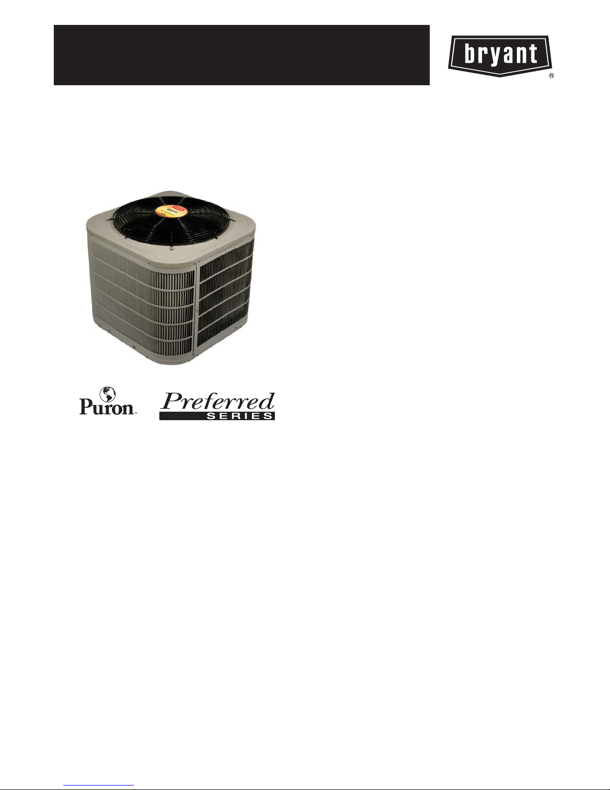
MODEL 226A
PREFERRED SERIES 2--STAGE HEAT PUMP
WITH PURONREFRIGERANT
2 TO 5 NOMINAL TONS
Product Data
TM
the environmentally sound refrigerant
Bryant’s heat pumps with Puronr refrigerant provide a collection
of features unmatched by any other family of equipment. The
226A has been designed utilizing Bryant’s Puron refrigerant. The
environmentally sound refrigerant allows consumers to make a
responsible decision in the protection of the earth’s ozone layer.
This product has been designed and manufactured to meet Energy
Starr criteria for energy efficiency when matched with appropriate
coil components. Refer to the combination ratings in the Product
Data for system combinations that meet Energy Starr guidelines.
NOTE: Ratings contained in this document are subject to
change at any time. Always refer to the AHRI directory
(www.ahridirectory.org) for the most up--to--date ratings
information.
INDUSTRY LEADING
FEATURES / BENEFITS
Energy Efficiency
S 13.7 -- 17.2 SEER/11.2 -- 13.5 EER/8.0 -- 9.5 HSPF
S Microtube Technologyt refrigeration system
S Indoor air quality accessories available
Sound
S Sound level as low as 70 dBA
Comfort
S System supports Thermidistatt or standard 2--stage thermostat
controls
Reliability
S Puronr refrigerant -- environmentally sound, won’t deplete the
ozone layer and low lifetime service cost.
S Front--seating service valves
S 2--stage scroll compressor
S Internal pressure relief valve
S Internal thermal overload
S High pressure switch
S Loss of charge switch
S Filter drier
S Balanced refrigeration system for maximum reliability
Durability
DuraGuard Plust protection package:
S Solid, Durable sheet metal construction
S Steel louver coil guard
S Baked--on, complete outer coverage, powder paint
Applications
S Long--line -- up to 250 feet (76.2 m) total equivalent length, up
to 200 feet (60.96 m) condenser above evaporator, or up to 80 ft.
(24.38 m) evaporator above condenser (See Longline Guide for
more information.)
Page 2
MODEL NUMBER NOMENCLATURE
12345 678910111214
N N N A A/N N N N N A/N A/N N A
226AN A03600 0 A
226A
Product
Famil y
2=HP 2=
Tier SEER Major
Legacy
the environmentally sound refrigerant
6=16 SEER A=Puron N=
Series
Series
Use of the AHRI Certified
TM Mark indicates a
manufacturer’s
participation in the
program For verification
of certification for individual
products, go to
www.ahridirectory.org.
Voltage Variations Cooling Capacity Open Open Open Series
208--- 230--- 1
or 208/ 230 --- 1
STANDARD FEATURES
FEATURES
A=Standard 0=Not
Defined
Unit Size --- Voltage, Series
024---B 036---B 048---B 060--- C
0=Not
Defined
This product has been designed and manuf actured to
meet Energy Star criteria for energy efficiency when
matched wit h appropriate coil components. However,
proper refri gerant c harge and proper ai r fl ow are cri tical
to achieve rated capacity and efficiency. Installation of
this product should follow all manufacturing refrigerant
charging and air flow instructions. Failure to confirm
proper charge and air flow may reduce energy
efficiency and shorten equipment life.
0=Not
Defined
A = Original
Series
Puron Refrigerant X X X X
Maximum SEER Rating* 17.2 17.0 16.5 16.0
2--- Stage Scroll Compressor X X X X
Louvered Coil Guard X X X X
FieldInstalledFilterDrier X X X X
Front Seating Service Valves X X X X
Internal Pressure Relief Valve X X X X
Long Line capability X X X X
Loss of Charge Switch X X X X
High Pressure Switch X X X X
Crankcase Heater X X X X
X=Standard
* With approved combinations
2
Page 3
PHYSICAL DATA
UNIT SIZE SERIES 024--- B 036--- B 048--- B 060--- C
Operating Weight lb (kg) 257 (117) 269 (122) 295 (134) 322 (146)
Shipping Weight lb (kg) 301 (137) 313 (142) 339 (154) 368 (167)
Compressor Type Ultratechr Scroll
REFRIGERANT Puronr (R---410A)
Control TXV (Puron Hard Shutoff)
Charge lb (kg) 13.07 (5.93) 13.70 (6.21) 13.73 (6.23) 14.78 (6.70)
Outdoor Htg Piston # 46 55 61 67
COND FAN Propeller Type, Direct Drive
Air Discharge Vertical
Air Qty (CFM) 3200 3200 4350 5000
Motor HP 1/12 1/ 12 1/4 1/4
Motor RPM 800 800 825 825
COND COIL
Face Area (Sq ft ) 25.2 25.2 25.2 30.18
Fins per In. 20 20 20 20
Rows 2 2 2 2
Circuits 8 8 8 10
VALVECONNECT.(In.ID)
Vapor 3/4 7/8 7/8 7/8
Liquid 3/8
REFRIGERANT TUBES (In. OD)
Rated Vapor* 3/4 7/8 1 --- 1 / 8 1 --- 1 / 8
Max L iquid Line 3/8
* Units are rated with 25 ft (7.6 m) of lineset length. See Vapor Line Sizing and Cooling Capacity Loss table when using other sizes and lengths of lineset.
Note: See unit Installation Instruction for proper installation.
226A
VAPOR LINE SIZING AND COOLING CAPACITY LOSS
Acceptable vapor line diameters provide adequate oil return to the compressor while avoiding excessive capacity loss. The suction line
diameters shown in the chart below are acceptable for AC systems with Puron refrigerant:
Cooling C apacity Loss (%)
Unit
Nominal
Size
(Btuh)
24,000
2 --- S t a g e
HP with
Puron
36,000
2 --- S t a g e
HP with
Puron
48,000
2 --- S t a g e
HP with
Puron
60,000
2 --- S t a g e
HP with
Puron
Standard Length = 80 ft. (24.4 m) or less total equivalent length
Applications in this area are long line. Accessories are required as shown recommended on Long Line Application Guidelines
Applications in this area may have height restrictions that limit allowable total equivalent length, when outdoor unit is below indoor unit.
— Applications in this area are not recommended due to insuficient oil return.
Maximum
Liquid Line
Diameters
(In. OD)
3/8
3/8
3/8
3/8
Vapo r Line
Diameters
(In.) OD
5/8 0 1 1 2 3 3 4 4 5
3/4 0 1 1 1 1 1 1 1 1
5/8 1 2 4 5 6 7 9 10 11
3/4 0 0 1 1 2 2 3 3 4
7/8 0 0 — — — — — — —
3/4 1 2 2 3 4 5 6 7 7
7/8 0 1 1 2 2 2 3 3 4
1 --- 1 / 8 0 0 — — — — — — —
3/4 1 2 4 5 6 8 9 10 11
7/8 0 1 2 2 3 4 4 5 5
1 --- 1 / 8 0 0 — — — — — — —
Standard
Application
26--- 50
(7.9---15.2)
51--- 80
(15.5---24.4)
81--- 100
(24.7---30.5)
Total Equivalent Line Length ft. (m)
Long Line Application Requires Acce ssories
101--- 125
(30.8---38.1)
126--- 150
(38.4---45.7)
151--- 175
(46.0---50.3)
176--- 200
(53.6---60.0)
201--- 225
(61.3---68.6)
226--- 250
(68.9---76.2)
3
Page 4
REFRIGERANT PIPING LENGTH LIMITATIONS
Maximum Line Lengths:
The maximum allowable total equivalent length for heat pumps varies depending on the vertical separation. See the tables below for
allowable lengths depending on whether the outdoor unit is on the same level, above or below the outdoor unit.
Maximum Line Lengths for Heat Pump Applications
MAXIMUM ACTUAL LENGTH
Units on equal level 200 (61) 250 (76.2) N/A
Outdoor unit ABOVE
indoor unit
Outdoor unit BELOW
indoor unit
{ Total equivalent length accounts for losses due to elbows or fitting. See the Long Line Guideline for details.
ft (m)
200 (61) 250 (76.2) 200 (61)
See Table ’Maximum Total Equivalent Length: Outdoor Unit BELOW Indoor Unit’
Maximum Total Equivalent Length{-- Outdoor Unit BELOW Indoor Unit
Liquid Line
Size
024
HP with
226A
Puron
036
HP with
Puron
048
HP with
Puron
060
HP with
Puron
* Maximum actual length not to exceed 200 ft (61 m)
{ Total equivalent length accounts for losses due to elbows or fitting. See the Long Line Guideline for details.
--- --- = o u t s i d e a c c e p t a b l e r a n g e
Diameter
w/ TXV
3/8 250* 250* 250* 250* 250* 250* 250*
3/8 250* 250* 250* 250* 250* 250* 250*
3/8 250* 250* 250* 250* 230 160 --- ---
3/8 250* 225* 190 150 110 --- --- --- ---
0 --- 2 0
(0 --- 6.1)
21--- 30
(6.4 - -- 9.1)
HP with Puronr Refrigerant --- Maximum Total Equivalent Length{
Vertical Separation ft (m) Outdoor unit BELOW indoor unit;
31--- 40
(9.4 - -- 12.2)
MAXIMUM EQUIVALENT LENGTH{
41--- 50
(12.5 - -- 15.2)
ft (m)
51--- 60
(15.5 - -- 18.3)
MAXIMUM VERTICAL SEPARA-
61--- 70
(18.6 - -- 21.3)
TION ft (m)
(21.6 - -- 24.4)
71--- 80
LONG LINE APPLICATIONS
An application is considered Long Line when the refrigerant level in the system requires the use of accessories to maintain acceptable
refrigerant management for systems reliability. Defining a system as long line depends on the liquid line diameter, actual length of the tubing,
and vertical separation between the indoor and outdoor units.
For Heat Pump systems, the chart below shows when an application is considered Long Line. Beyond these lengths, long line accessories
are required:
HP WITH PURONr REFRIGERANT LONG LINE DESCRIPTION ft (m)
Beyond these lengths, long line accessories are required
Liquid Line Size Units On Same Level Outdoor Below Indoor Outdoor Above Indoor
3/8 80 (24.4) 20 (6.1) vertical or 80 (24.4) total 80 (24.4)
Note: SeeLongLineGuidelinefordetails
THERMOSTATS
PAR T NUM BE R PROGRAM ELECTRIC HEAT PUMP HEAT COOL
T2 ---PHP01 5 --- 2 D a y
T 2 --- N H P 0 1 NP
T2SNHP01 NP
THERMOSTAT ACCESSORIES
PAR T NUM BE R BRIEF DESCRIPTION THERMOSTATS USED WITH
TSTATXXCNV10 Thermostat Conversion Kit (4 to 5 wire) --- 10 pack All Bryantr branded thermostats
T X --- L B P 0 1 LargeDecorativeBackplate T 6 --- P x x , T 6 --- N x x , a n d T 2 --- P x x
T X --- M B P 0 1 Medium Decorative Backplate T 2 --- N x x a n d T 1 --- P x x
√ √
√ √
√ √
3 2
3 2
2 1
4
Page 5
ACCESSORIES
KIT NUMBER KIT NAME 024--- B 036 -- -B 048 --- B 060 -- -C
KHALS0401LLS SOLENOID VALVE X X X X
KHASS0606MPK* SNOW STAND X X X X
KSAHS2501AAA{ HARD START KIT X X
KSAHS2801AAA{ HARD START KIT X X
KSASF0101AAA SUPPORT FEET X X X X
KSASH2301COP SOUND BLANKET X X
KSASH2401COP SOUND BLANKET X X
x = Accessory S = Standard
*AvailablefromRCD
{ Not backward compatible to previous series.
ACCESSORY USAGE GUIDELINE
Accessory
Compressor Start Assist Capacitor and Relay Ye s No
* For tubing line sets between 80 and 200 ft. (24.38 and 60.96 m) and/or 20 ft. (6.09 m) vertical differential, refer to Residential Piping and Longline Guideline.
Accumulator Standard Standard
Crankcase Heater
Hard Shutoff TXV
Liquid Line Solenoid Valve See Long ---Line Application Guideline No
Support Feet Recommended Recommended
(Standard with factory---approved indoor unit)
REQUIRED FOR
LONG LINE APPLICATIONS*
Standard
Ye s
Accessory Description and Usage (Listed Alphabetically)
1. Compressor Start Assist -- Capacitor and Relay
Start capacitor and relay gives a “hard” boost to compressor motor
at each start up.
Usage Guideline:
Required for reciprocating compressors in the following
applications:
Long line
Low ambient cooling
Hard shut off expansion valve on indoor coil
Liquid line solenoid on indoor coil
Required for single--phase scroll compressors in the
following applications:
Long line
Low ambient cooling
Suggested for all compressors in areas with a history of
low voltage problems.
2. Crankcase Heater
An electric resistance heater which mounts to the base of the
compressor to keep the lubricant warm during off cycles. Improves
compressor lubrication on restart and minimizes the chance of
liquid slugging.
Usage Guideline:
Required in low ambient cooling applications.
Required in long line applications.
Suggested in all commercial applications.
3. Liquid--Line Solenoid Valve (LLS)
An electrically operated shutoff valve which stops and starts
refrigerant liquid flow in response to compressor operation. It is to
be installed at the outdoor unit to control refrigerant off cycle
migration in the heating mode.
Usage Guideline:
An LLS is required in all long line heat pump
applications to control refrigerant off cycle migration in
t he heating mode. See Long Line Guideline.
Suggested for all commercial applications.
4. Outdoor Air Temperature Sensor
Designed for use with Bryant Thermostats listed in this
publication. This device enables the thermostat to display the
outdoor temperature. This device also is required to enable special
thermostat features such as auxiliary heat lock out.
Usage Guideline:
Suggested for all Bryant thermostats listed in this
publication.
5. Outdoor Thermostat
An SPDT temperature--actuated switch which turns on
supplemental electric heaters when outdoor air temperature drops
below a user--selected set point.
Usage Guideline:
Electric supplemental heat applications in non--variable
speed indoor units when electric heat staging is desired.
6. Secondary Outdoor Thermostat
An SPDT temperature--actuated switch which turns on third--stage
of supplemental electric heaters when outdoor air temperature
drops below the second--stage set point.
Usage Guideline:
Outdoor thermostat applications where electric heater is
capable of three--stage operation.
7. Snow Stand
Coated wire rack which supports unit 18 in. (457.2 mm) above
mounting pad to allow for drainage from unit base.
Usage Guideline:
Suggested in the following applications:
Heat pump installations in heavy snowfall areas.
Heat pump installations in snow drift locations.
Heat pump installations in areas of prolonged
subfreezing temperatures.
All commercial installations.
8. Thermostatic Expansion Valve (TXV) Bi--Flow
A modulating flow--control valve which meters refrigerant liquid
flow rate into the evaporator in response to the superheat of the
refrigerant gas leaving the evaporator.
Usage Guideline:
Accessory required to meet AHRI rating and system
reliability, where indoor not equipped.
Required in all heat pump applications designed with
Puron refrigerant.
REQUIRED FOR
SEA COAST APPLICATIONS
(Within 2 miles / 3.22 km)
Standard
Ye s
226A
5
Page 6
ELECTRICAL DATA
UNIT
S I Z E ---
VOLTAGE,
SERIES
024--- B
036--- B 83.0 18.5 0.6 23.7 12 12 52 (16.0) 50 (15.3) 40
048--- B 104.0 22.8 1.3 29.8 10 10 67 (20.4) 63 (19.4) 50
060--- C 152.9 28.8 1.5 37.5 8 8 82 (25.2) 78 (24.0) 60
* Permissible limits of the voltage range at which the unit will operate satisfactorily
{ If wire is applied at ambient greater th an 30_C , c o n s u l t t a b l e 3 1 0 --- 1 6 o f t h e N E C ( N F P A 7 0 ) . T h e a m p a c i t y o f n o n --- m e t a l l i c --- s h e a t h e d c a b l e ( N M ) ,
trade name ROMEX, shall be that of 60_C conditions, per the NEC (NFPA 70) Article 336 ---26. If other than uncoated (no---plated), 60 or 75_C
insulation, copper wire (solid wire for 10 AWG or smaller, stranded wire for larger than 10 AWG) is used, consult applicable tables of the NEC (NFPA 70).
} Length shown is as measured 1 way along wire path between unit and service panel for voltage drop not to exceed 2%.
* * T i m e --- D e l a y f u s e .
FLA --- Fu l l L o a d A m p s
LRA --- L o c k e d R o t o r A m p s
M C A --- Minimum Circuit Amps
RLA --- RatedLoadAmps
NOTE: Control circuit is 24 ---V on all units and requires external power source. Copper wire must be used from service disconnect to unit.
All motors/compressors contain internal overload protection.
Complies with 2010 requirements of ASHRAE Standards 90.1
226A
SOUND POWER LEVEL (dBA)
Unit Size
--- V o l t a g e ,
Series
024--- B
036--- B
048--- B
060--- C
NOTE: Tested in compliance with AHRI 270 --- 2008 but not listed with AHRI.
V/PH
208---230/1 253 197
Standard Rating dBA
7 3 --- H i g h S t a g e 51.5 55.0 63.5 69.0 62.0 58.5 56.0
7 4 --- H i g h S t a g e 54.5 57.5 65.0 70.5 62.5 60.0 57.0
7 5 --- H i g h S t a g e 53.5 59.5 66.0 70.5 64.0 61.5 55.0
7 4 --- H i g h S t a g e 51.5 58.0 66.0 68.0 64.5 63.0 61.5
OPER VOLTS* COMPR FAN
MCA
MAX MIN LRA RLA FLA 60C 75C 60C 75C
58.3 12.5 0.6 16.2 14 14 48 (14.8) 46 (14.1) 25
TYPICAL OCTAVE BAND SPECTRUM (dBA, without tone adjustment)
125 250 500 1000 2000 4000 8000
7 0 --- L o w S t a g e 51.5 55.5 63.0 66.0 62.0 59.0 54.0
7 1 --- L o w S t a g e 54.0 57.5 63.5 66.0 61.0 60.5 55.0
7 1 --- L o w S t a g e 54.0 59.5 66.0 66.0 63.0 61.5 55.5
7 3 --- L o w S t a g e 53.0 58.5 66.5 68.0 64.5 63.0 58.5
MIN
WIRE
SIZE{
MIN
WIRE
SIZE{
MAX
LENGTH
ft (m)}
MAX
LENGTH
ft (m)}
MAX
FUSE*
*or
CKT
BRK
AMPS
SOUND POWER LEVEL (dBA) WITH ACCESSORY SOUNDSHIELD
Unit Size
--- V o l t a g e ,
Series
024--- B
036--- B
048--- B
060--- C
NOTE: Tested in compliance with AHRI 270 --- 2008 but not listed with AHRI.
Standard Rating dBA
7 1 --- H i g h S t a g e 50.0 55.0 63.0 68.0 61.5 57.5 52.0
7 0 --- L o w S t a g e 50.5 56.0 63.0 66.0 61.5 58.0 51.5
7 2 --- H i g h S t a g e 54.5 57.0 64.5 69.0 61.5 58.5 53.0
7 0 --- L o w S t a g e 55.5 56.5 63.0 65.0 60.5 59.0 52.0
7 4 --- H i g h S t a g e 54.0 59.5 66.0 70.0 63.0 59.0 51.5
7 0 --- L o w S t a g e 53.5 59.0 65.5 65.0 62.5 60.5 54.0
7 3 --- H i g h S t a g e 52.0 58.5 66.0 68.0 64.0 60.5 56.5
7 2 --- L o w S t a g e 54.0 58.0 66.0 67.5 64.0 61.0 55.0
125 250 500 1000 2000 4000 8000
CHARGING SUBCOOLING (TXV--TYPE EXPANSION DEVICE)
UNIT SIZE --- VOLTAGE, SERIES REQUIRED SUBCOOLING _F(_C)
024--- B 10 (5.6)
036--- B 13 (7.2)
048--- B 12 (6.7)
060--- C 11 (6.1)
TYPICAL OCTAVE BAND SPECTRUM (dBA, without tone adjustment)
6
Page 7
226A
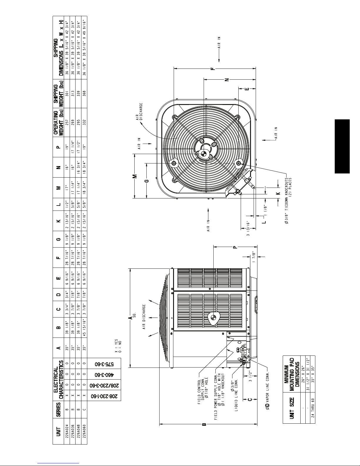
DIMENSIONS -- ENGLISH
7
Page 8

226A
DIMENSIONS -- SI
8
Page 9

226ANA060
FV4CNB006
226ANA048
FV4CN(B,F)005
226ANA036
FV4CNB006
226ANA024
FV4CNF002
BASED ON INDOOR ENT. AIR AT
70ºF 21.1ºC AND AT RATED CFM
226A
80
70
60
226A BALANCE POINT WORKSHEET -- HIGH STAGE
50
40
OUTDOOR TEMPERATURE, ºF( ºC)
0 (-17.8) 10 (-12.2) 20 (-6.7) 30 (-1.1) 40 (4.4) 50 (10.0) 60 (15.6) 70 (21.1) 80 (26.7)
-10 (-23.3)
30
20
HEATING CAPACITY, MBTUH
10
0
BUILDING HEAT LOSS, UNIT INTEGRATED
9
Page 10

226ANA060
FV4CNB006
226ANA048
FV4CN(B,F)005
226ANA036
FV4CNB006
226A
226ANA024
FV4CNF002
BASED ON INDOOR ENT. AIR AT
70ºF 21.1ºC AND AT RATED CFM
60
50
226A BALANCE POINT WORKSHEET -- LOW STAGE
40
30
10
20
OUTDOOR TEMPERATURE, ºF( ºC)
0 (-17.8) 10 (-12.2) 20 (-6.7) 30 (-1.1) 40 (4.4) 50 (10.0) 60 (15.6) 70 (21.1) 80 (26.7)
-10 (-23.3)
10
0
HEATING CAPACITY, MBTUH
BUILDING HEAT LOSS, UNIT INTEGRATED
Page 11

Wall
6”
A07833
(152.4)
24”
Wall
Clearances (various examples)
Service
12”
(304.8)
6”
Wall
(152.4 mm)
12”
(304.8)
12”
(304.8)
12”
(304.8)
Wall
24”
(609.6)
24”
(609.6)
24”
(609.6)
Service
Service
Service
226A
24”
(609.6)
24”
(609.6)
24”
CLEARANCES
(609.6)
Service
11
24”
(609.6)
Note: Numbers in ( ) = mm
IMPORTANT: When installing multiple units in an alcove, roof well, or partially enclosed area, ensure there is adequate ventilation to prevent re--circulation of discharge air.
Page 12

226A
Low Temp
ID CFM High Temp
COP
Capacity
HSPF
COP
Capacity
High Low
17˚F ( --- 8 ˚C)
47˚F(8˚C)
Cooling Heating
EER SEER
Cooling
Capacity
Model Number Coil Model Number Furnace M odel N umber
226ANA024****B FV4CNF002 24,000 13.0 17.0 700 560 25,000 3.90 9.0 15,300 2.74
226ANA036****B FV4CNB006 36,400 13.3 17.0 1050 840 35,800 4.06 9.5 22,600 3.00
226ANA048****B FV4CN(B,F)005 47,000 12.5 16.0 1400 1120 47,000 3.68 9.0 29,200 2.72
226ANA060****C FV4CNB006 56,500 12.5 16.0 1750 1400 58,000 3.72 9.0 36,000 2.76
TESTED AHRI COMBINATION RATINGS*
NOTE: Ratings contained in this document are subject to change at any time.
For AHRI ratings certificates, please refer to the AHRI directory www.ahridirectory.org
Additional ratings and system combinations can be accessed via the Bryant database at: http://cactaxcredits.info/bryant-ratings/hp_ratings_srch.php
Equipment performance calculator can be accessed at: http://rpmobbry.wrightsoft.com/
Ratings are net values reflecting the effects of circulating fan heat. Supplemental electric heat is not included. Ratings are based on:
Cooling Standard: 80_F(27_C) db 67_F(19_C) wb indoor entering air temperature and 95_F(35_C) db air entering outdoor unit.
High--- Temp Heating Standard: 70_F(21_C) db indoor entering air temperature and 47_F(8_C) db 43° F (6_C) wb air entering outdoor unit.
Low --- Temp Heating Standard: 70_F(21_C) db indoor entering air temperature and 17_F ( --- 8 _C) db 15° F ( ---9_C) wb air entering outdoor unit.
COP — Coefficient of Performance
EER — Energy Efficiency Ratio
HSPF — Heating Seasonal Performance Factor
* AHRI = Air Conditioning, Heating & Refrigeration Institute
SEER — Seasonal Energy Efficiency Ratio
12
Page 13

Tot a l
KW**
System
Capacity MBtu h†
Tot a l
KW**
System
Capacity MBtu h†
226A
Tot a l
KW**
System
Capacity MBtu h†
Tot a l
KW**
System
CONDENSER ENT ERING AIR TEMPERATURES ° F ( ° C)
Capacity MBtu h†
Tot a l
KW**
226ANA024****B Outdoor Section With FV4CNF002 Indoor Section --- HI
System
Capacity MBtu h†
Tot a l
KW**
System
226ANA024****B Outdoor Section With FV4CNF002 Indoor Section --- LO
75 (23.9) 85 (29.4) 95 (35) 105 ( 40.6) 115 (46. 1) 125 ( 51.7)
Capacity MBtu h†
Tot a l Sens ‡ Tot a l Sens‡ To t al Sens‡ To t al Sen s‡ Tot a l Sen s‡ To ta l Sen s‡
22.47 22.47 1.42 21.26 21.26 1.60 20.00 20.00 1.81 18.69 18.69 2.06 17.34 17.34 2.35 15.96 15.96 2.72
24.04 20.32 1.43 22.54 19.39 1.61 20.99 18.43 1.82 19.39 17.45 2.06 17.77 16.44 2.36 16.14 15.39 2.72
24.52 16.88 1.43 22.99 16.03 1.61 21.40 15.16 1.82 19.77 14.27 2.06 18.10 13.37 2.36 16.39 12.47 2.72
26.60 17.58 1.44 24.94 16.71 1.62 23.23 15.82 1.83 21.47 14.92 2.07 19.68 14.02 2.37 17.86 13.10 2.73
29.45 14.67 1.46 27.62 13.88 1.64 25.73 13.07 1.84 23.80 12.26 2.09 21.84 11.45 2.38 19.84 10.63 2.74
23.20 23.20 1.43 21.94 21.94 1.61 20.62 20.62 1.82 19.26 19.26 2.07 17.86 17.86 2.36 16.42 16.42 2.73
24.52 21.24 1.44 22.98 20.27 1.62 21.39 19.27 1.82 19.75 18.25 2.07 18.11 17.18 2.37 16.46 16.46 2.73
25.01 17.53 1.44 23.43 16.66 1.62 21.79 15.76 1.83 20.11 14.85 2.07 18.40 13.93 2.37 16.65 13.00 2.73
27.11 18.28 1.45 25.41 17.38 1.63 23.64 16.47 1.84 21.83 15.54 2.08 20.00 14.61 2.38 18.13 13.67 2.74
30.01 15.16 1.47 28.12 14.35 1.65 26.17 13.52 1.85 24.19 12.70 2.10 22.17 11.86 2.39 20.13 11.01 2.74
EWB
°F (°C)
57 (13.9)
62 (16.7)
67 (19.4)
72 (22.2)
57 (13.9)
62 (16.7)
67 (19.4)
63 (17.2)††
EVAPORATOR A IR
CFM
600
63 (17.2)††
650
72 (22.2)
DETAILED COOLING CAPACITIES#
23.88 23.88 1.44 22.56 22.56 1.62 21.20 21.20 1.83 19.78 19.78 2.08 18.33 18.33 2.37 16.84 16.84 2.74
24.95 22.13 1.45 23.38 21.12 1.63 21.74 20.08 1.83 20.08 19.01 2.08 18.42 18.27 2.37 16.87 16.87 2.74
25.44 18.16 1.45 23.82 17.27 1.63 22.14 16.35 1.84 20.41 15.41 2.08 18.65 14.47 2.38 16.87 13.52 2.74
27.57 18.95 1.46 25.81 18.03 1.64 24.00 17.09 1.85 22.15 16.14 2.09 20.27 15.19 2.39 18.36 14.23 2.74
30.50 15.64 1.48 28.55 14.80 1.65 26.55 13.96 1.86 24.52 13.11 2.10 22.46 12.24 2.40 20.38 11.37 2.75
25.06 25.06 1.46 23.66 23.66 1.64 22.20 22.20 1.85 20.69 20.69 2.09 19.15 19.15 2.39 17.57 17.57 2.75
25.69 23.81 1.46 24.06 22.72 1.64 22.38 21.57 1.85 20.73 20.73 2.10 19.18 19.18 2.39 17.60 17.60 2.75
26.15 19.37 1.47 24.45 18.44 1.65 22.69 17.47 1.85 20.90 16.49 2.10 19.08 15.51 2.39 17.23 14.51 2.75
28.31 20.24 1.48 26.48 19.28 1.66 24.59 18.30 1.86 22.66 17.31 2.11 20.71 16.31 2.40 18.74 15.30 2.76
31.29 16.52 1.49 29.26 15.64 1.67 27.18 14.75 1.87 25.08 13.85 2.12 22.94 12.95 2.41 20.79 12.04 2.77
17.40 17.40 1.02 16.19 16.19 1.19 14.92 14.92 1.39 13.64 13.64 1.62 12.37 12.37 1.89 11.13 11.13 2.20
18.34 16.19 1.02 16.89 15.05 1.19 15.38 13.92 1.39 13.87 12.77 1.62 12.43 12.34 1.89 11.15 11.15 2.20
18.71 13.35 1.01 17.22 12.36 1.18 15.67 11.36 1.38 14.11 10.38 1.62 12.58 9.42 1.89 11.11 8.51 2.20
20.36 13.94 1.00 18.74 12.92 1.17 17.07 11.90 1.37 15.40 10.90 1.60 13.77 9.91 1.88 12.20 8.98 2.19
22.60 11.57 0.98 20.80 10.66 1.15 18.96 9.76 1.35 17.13 8.89 1.59 15.35 8.03 1.86 13.64 7.21 2.19
17.97 17.97 1.02 16.71 16.71 1.19 15.39 15.39 1.39 14.05 14.05 1.62 12.74 12.74 1.89 11.45 11.45 2.20
18.72 16.93 1.02 17.22 15.75 1.19 15.68 14.56 1.39 14.15 13.34 1.62 12.76 12.76 1.89 11.47 11.47 2.20
19.08 13.89 1.01 17.54 12.86 1.19 15.95 11.83 1.39 14.35 10.82 1.62 12.79 9.83 1.89 11.28 8.88 2.20
20.75 14.52 1.00 19.07 13.46 1.17 17.36 12.41 1.37 15.65 11.37 1.61 13.98 10.37 1.88 12.37 9.39 2.20
23.02 11.97 0.98 21.16 11.04 1.15 19.27 10.11 1.35 17.40 9.21 1.59 15.58 8.32 1.87 13.83 7.48 2.19
18.49 18.49 1.02 17.17 17.17 1.19 15.81 15.81 1.39 14.43 14.43 1.62 13.07 13.07 1.89 11.74 11.74 2.21
19.05 17.65 1.02 17.51 16.42 1.19 15.96 15.15 1.39 14.46 14.46 1.62 13.09 13.09 1.89 11.76 11.76 2.21
19.40 14.41 1.02 17.81 13.35 1.19 16.19 12.29 1.39 14.55 11.24 1.62 12.96 10.23 1.89 11.43 9.24 2.21
21.08 15.07 1.00 19.37 13.99 1.17 17.61 12.90 1.37 15.87 11.83 1.61 14.16 10.80 1.88 12.52 9.80 2.20
23.38 12.35 0.98 21.47 11.41 1.15 19.54 10.45 1.35 17.63 9.50 1.59 15.78 8.60 1.87 14.00 7.73 2.20
19.40 19.40 1.03 18.00 18.00 1.20 16.55 16.55 1.40 15.08 15.08 1.63 13.64 13.64 1.90 12.24 12.24 2.22
19.63 18.98 1.03 18.07 17.96 1.20 16.57 16.57 1.40 15.11 15.11 1.63 13.67 13.67 1.90 12.26 12.26 2.22
19.92 15.40 1.03 18.26 14.29 1.20 16.58 13.16 1.40 14.89 12.06 1.63 13.25 10.97 1.91 11.67 9.93 2.22
21.63 16.14 1.01 19.84 14.99 1.18 18.02 13.84 1.38 16.21 12.71 1.62 14.45 11.61 1.90 12.77 10.55 2.22
23.96 13.07 0.99 21.98 12.06 1.16 19.98 11.05 1.36 18.01 10.06 1.60 16.09 9.12 1.88 14.25 8.22 2.21
57 (13.9)
62 (16.7)
67 (19.4)
72 (22.2)
57 (13.9)
62 (16.7)
67 (19.4)
72 (22.2)
57 (13.9)
62 (16.7)
67 (19.4)
72 (22.2)
57 (13.9)
62 (16.7)
67 (19.4)
72 (22.2)
57 (13.9)
62 (16.7)
67 (19.4)
72 (22.2)
57 (13.9)
62 (16.7)
67 (19.4)
63 (17.2)††
700
63 (17.2)††
800
63 (17.2)††
480
63 (17.2)††
520
63 (17.2)††
560
63 (17.2)††
640
72 (22.2)
See notes on pg. 16
13
Page 14

226A
Tot a l
KW**
System
Capacity MBtu h†
Tot a l
KW**
System
Capacity MBtu h†
Tot a l
KW**
System
Capacity MBtu h†
Tot a l
KW**
System
CONDENSER ENT ERING AIR TEMPERATURES ° F ( ° C)
Capacity MBtu h†
Tot a l
KW**
226ANA036****B Outdoor Section With FV4CNB006 Indoor Section--- HI
System
Capacity MBtu h†
Tot a l
KW**
System
226ANA036****B Outdoor Section With FV4CNB006 Indoor Section --- LO
75 (23.9) 85 (29.4) 95 (35) 105 ( 40.6) 115 (46. 1) 125 ( 51.7)
Capacity MBtu h†
Tot a l Sens ‡ Tot a l Sens‡ To t al Sens‡ To t al Sen s‡ Tot a l Sen s‡ To ta l Sen s‡
33.59 33.59 2.10 32.13 32.13 2.36 30.60 30.60 2.67 28.98 28.98 3.03 27.24 27.24 3.44 25.34 25.34 3.90
35.79 30.52 2.13 33.92 29.55 2.38 31.98 28.55 2.68 29.95 27.51 3.03 27.78 26.41 3.44 25.47 25.23 3.91
36.56 25.27 2.13 34.65 24.34 2.39 32.68 23.39 2.69 30.59 22.40 3.04 28.37 21.35 3.44 25.95 20.24 3.91
39.56 26.24 2.16 37.50 25.30 2.41 35.38 24.34 2.71 33.12 23.34 3.06 30.72 22.28 3.47 28.13 21.16 3.93
43.66 21.83 2.21 41.43 20.94 2.45 39.09 20.03 2.74 36.62 19.09 3.09 34.00 18.05 3.50 31.17 16.98 3.96
34.66 34.66 2.12 33.12 33.12 2.38 31.53 31.53 2.69 29.83 29.83 3.04 28.02 28.02 3.45 26.04 26.04 3.92
36.45 31.93 2.14 34.52 30.93 2.39 32.54 29.91 2.69 30.44 28.83 3.05 28.25 27.68 3.45 26.08 26.08 3.92
37.23 26.25 2.15 35.26 25.31 2.40 33.22 24.33 2.70 31.07 23.32 3.05 28.78 22.25 3.46 26.30 21.12 3.92
40.24 27.28 2.18 38.13 26.33 2.43 35.92 25.34 2.72 33.61 24.32 3.07 31.14 23.24 3.48 28.48 22.10 3.95
44.40 22.51 2.22 42.08 21.60 2.46 39.68 20.67 2.76 37.15 19.70 3.10 34.44 18.66 3.51 31.56 17.58 3.98
EWB
°F (°C)
57 (13.9)
62 (16.7)
67 (19.4)
72 (22.2)
57 (13.9)
62 (16.7)
67 (19.4)
63 (17.2)††
EVAPORATOR A IR
CFM
900
63 (17.2)††
975
72 (22.2)
DETAILED COOLING CAPACITIES# CONTINUED
35.64 35.64 2.14 34.03 34.03 2.40 32.38 32.38 2.70 30.61 30.61 3.06 28.73 28.73 3.47 26.66 26.66 3.94
37.04 33.31 2.16 35.06 32.28 2.41 33.03 31.22 2.71 30.91 30.11 3.06 28.77 28.77 3.47 26.70 26.70 3.94
37.80 27.21 2.16 35.78 26.24 2.41 33.69 25.26 2.71 31.48 24.22 3.07 29.13 23.13 3.47 26.60 21.97 3.94
40.84 28.30 2.20 38.66 27.32 2.44 36.40 26.32 2.74 34.03 25.28 3.09 31.49 24.18 3.49 28.79 23.03 3.96
45.03 23.16 2.24 42.65 22.24 2.48 40.20 21.29 2.77 37.60 20.30 3.12 34.83 19.26 3.52 31.88 18.16 3.99
37.35 37.35 2.18 35.63 35.63 2.43 33.86 33.86 2.74 31.97 31.97 3.09 29.94 29.94 3.50 27.74 27.74 3.97
38.04 35.95 2.19 36.01 34.85 2.44 33.95 33.86 2.74 32.02 32.02 3.09 29.98 29.98 3.50 27.78 27.78 3.97
38.75 29.06 2.19 36.63 28.06 2.44 34.43 27.03 2.74 32.13 25.96 3.09 29.69 24.84 3.50 27.07 23.64 3.96
41.80 30.27 2.23 39.53 29.26 2.47 37.17 28.23 2.76 34.71 27.15 3.11 32.08 26.02 3.52 29.28 24.82 3.99
46.06 24.41 2.27 43.58 23.47 2.51 41.01 22.49 2.80 38.32 21.48 3.15 35.44 20.41 3.55 32.39 19.28 4.02
25.97 25.97 1.44 24.13 24.13 1.73 22.32 22.32 2.06 20.47 20.47 2.46 18.58 18.58 2.93 16.64 16.64 3.49
27.04 24.32 1.44 24.89 22.65 1.72 22.77 21.00 2.06 20.65 19.36 2.46 18.62 18.62 2.93 16.67 16.67 3.49
27.62 19.90 1.43 25.41 18.43 1.72 23.23 17.00 2.05 21.04 15.58 2.46 18.80 14.16 2.93 16.53 12.76 3.49
30.03 20.80 1.41 27.65 19.26 1.70 25.29 17.79 2.04 22.92 16.32 2.44 20.50 14.87 2.91 18.05 13.43 3.47
33.45 17.17 1.38 30.80 15.82 1.67 28.18 14.50 2.01 25.56 13.21 2.41 22.91 11.93 2.88 20.21 10.66 3.44
26.78 26.78 1.44 24.87 24.87 1.72 22.98 22.98 2.06 21.07 21.07 2.46 19.11 19.11 2.93 17.10 17.10 3.49
27.53 25.51 1.44 25.33 23.77 1.72 23.18 22.04 2.06 21.11 21.11 2.46 19.14 19.14 2.93 17.13 17.13 3.49
28.09 20.73 1.43 25.83 19.21 1.72 23.59 17.73 2.06 21.34 16.26 2.46 19.06 14.80 2.94 16.73 13.35 3.50
30.55 21.66 1.41 28.10 20.10 1.70 25.67 18.57 2.04 23.25 17.06 2.44 20.78 15.56 2.91 18.28 14.07 3.47
34.02 17.75 1.39 31.29 16.36 1.68 28.60 15.01 2.02 25.92 13.69 2.42 23.21 12.37 2.89 20.45 11.08 3.44
27.53 27.53 1.44 25.56 25.56 1.72 23.60 23.60 2.06 21.61 21.61 2.46 19.59 19.59 2.93 17.51 17.51 3.49
27.98 26.67 1.44 25.76 24.84 1.72 23.64 23.64 2.06 21.65 21.65 2.46 19.63 19.63 2.93 17.54 17.54 3.49
28.51 21.54 1.43 26.20 19.98 1.72 23.91 18.45 2.06 21.61 16.93 2.46 19.29 15.43 2.94 16.92 13.93 3.50
31.00 22.53 1.41 28.48 20.92 1.70 26.01 19.34 2.04 23.53 17.78 2.44 21.02 16.24 2.92 18.47 14.70 3.47
34.49 18.31 1.39 31.71 16.89 1.68 28.96 15.51 2.02 26.22 14.15 2.42 23.45 12.81 2.89 20.65 11.48 3.44
28.86 28.86 1.44 26.76 26.76 1.73 24.68 24.68 2.06 22.57 22.57 2.46 20.43 20.43 2.94 18.24 18.24 3.49
28.91 28.91 1.44 26.80 26.80 1.73 24.72 24.72 2.06 22.61 22.61 2.46 20.47 20.47 2.94 18.27 18.27 3.49
29.20 23.11 1.44 26.80 21.46 1.73 24.44 19.85 2.07 22.06 18.24 2.47 19.67 16.65 2.95 17.25 15.06 3.51
31.73 24.22 1.42 29.12 22.52 1.71 26.56 20.85 2.05 23.99 19.19 2.45 21.42 17.56 2.92 18.80 15.93 3.48
35.28 19.40 1.39 32.39 17.92 1.68 29.55 16.47 2.02 26.71 15.05 2.42 23.87 13.65 2.90 20.98 12.26 3.45
57 (13.9)
62 (16.7)
67 (19.4)
72 (22.2)
57 (13.9)
62 (16.7)
67 (19.4)
72 (22.2)
57 (13.9)
62 (16.7)
67 (19.4)
72 (22.2)
57 (13.9)
62 (16.7)
67 (19.4)
72 (22.2)
57 (13.9)
62 (16.7)
67 (19.4)
72 (22.2)
57 (13.9)
62 (16.7)
67 (19.4)
63 (17.2)††
1050
63 (17.2)††
1200
63 (17.2)††
720
63 (17.2)††
780
63 (17.2)††
840
63 (17.2)††
960
72 (22.2)
See notes on pg. 16
14
Page 15

Tot a l
KW**
System
Capacity MBtu h†
Tot a l
KW**
System
Capacity MBtu h†
226A
Tot a l
KW**
System
Capacity MBtu h†
Tot a l
KW**
System
CONDENSER ENT ERING AIR TEMPERATURES ° F ( ° C)
Capacity MBtu h†
Tot a l
KW**
System
226ANA048****B Outdoor Section With FV4CN(B,F)005 Indoor Section--- HI
Capacity MBtu h†
Tot a l
KW**
System
226ANA048****B Outdoor Section With FV4CN(B,F)005 Indoor Section--- LO
75 (23.9) 85 (29.4) 95 (35) 105 ( 40.6) 115 (46. 1) 125 ( 51.7)
Capacity MBtu h†
Tot a l Sens ‡ Tot a l Sens‡ To t al Sens‡ To t al Sen s‡ Tot a l Sen s‡ To ta l Sen s‡
42.70 42.70 2.91 41.39 41.39 3.26 39.86 39.86 3.66 38.17 38.17 4.13 36.35 36.35 4.69 34.44 34.44 5.34
45.46 39.41 2.92 43.68 38.56 3.27 41.63 37.58 3.67 39.40 36.53 4.14 37.07 35.41 4.69 34.69 34.21 5.35
46.41 32.56 2.93 44.59 31.70 3.28 42.48 30.72 3.68 40.18 29.67 4.15 37.76 28.58 4.70 35.25 27.48 5.35
50.09 33.77 2.95 48.12 32.90 3.30 45.85 31.92 3.70 43.40 30.88 4.18 40.80 29.80 4.74 38.11 28.70 5.40
55.10 27.96 2.98 52.90 27.06 3.33 50.43 26.08 3.74 47.76 25.04 4.22 44.93 23.95 4.78 41.99 22.85 5.45
43.94 43.94 2.94 42.57 42.57 3.29 40.96 40.96 3.69 39.18 39.18 4.16 37.28 37.28 4.72 35.28 35.28 5.38
46.21 41.13 2.95 44.38 40.25 3.30 42.26 39.25 3.70 39.98 38.15 4.17 37.61 36.96 4.72 35.34 35.34 5.38
47.15 33.75 2.96 45.26 32.87 3.31 43.09 31.87 3.71 40.71 30.81 4.18 38.22 29.71 4.73 35.64 28.59 5.38
50.86 35.03 2.98 48.81 34.14 3.33 46.48 33.15 3.73 43.94 32.10 4.21 41.27 31.01 4.77 38.51 29.90 5.43
55.89 28.74 3.00 53.62 27.84 3.36 51.07 26.84 3.77 48.32 25.79 4.25 45.41 24.70 4.81 42.39 23.58 5.48
EWB
°F (°C)
57 (13.9)
62 (16.7)
67 (19.4)
72 (22.2)
57 (13.9)
62 (16.7)
67 (19.4)
63 (17.2)††
EVAPORATOR A IR
CFM
1200
63 (17.2)††
1300
72 (22.2)
DETAILED COOLING CAPACITIES# CONTINUED
45.06 45.06 2.97 43.63 43.63 3.32 41.94 41.94 3.72 40.09 40.09 4.19 38.12 38.12 4.75 36.04 36.04 5.42
46.88 42.78 2.98 44.98 41.87 3.33 42.83 40.84 3.73 40.51 39.67 4.20 38.18 38.18 4.75 36.09 36.09 5.42
47.79 34.89 2.98 45.84 34.00 3.33 43.60 32.99 3.73 41.16 31.92 4.20 38.61 30.81 4.76 35.98 29.67 5.41
51.52 36.24 3.00 49.40 35.35 3.35 47.00 34.35 3.76 44.39 33.28 4.23 41.67 32.19 4.79 38.84 31.06 5.46
56.57 29.50 3.03 54.24 28.58 3.38 51.61 27.58 3.79 48.79 26.52 4.27 45.81 25.41 4.84 42.73 24.30 5.51
47.01 47.01 3.02 45.45 45.45 3.38 43.64 43.64 3.78 41.65 41.65 4.26 39.54 39.54 4.82 37.32 37.32 5.48
48.00 45.88 3.03 46.04 44.90 3.38 43.86 43.45 3.78 41.71 41.71 4.26 39.60 39.60 4.82 37.36 37.36 5.49
48.82 37.08 3.03 46.76 36.17 3.38 44.42 35.15 3.79 41.88 34.05 4.26 39.24 32.91 4.81 36.51 31.74 5.47
52.57 38.58 3.05 50.34 37.67 3.41 47.82 36.66 3.81 45.12 35.57 4.29 42.28 34.45 4.85 39.37 33.30 5.51
57.65 30.93 3.08 55.20 30.01 3.43 52.47 28.99 3.85 49.53 27.91 4.33 46.44 26.80 4.90 43.25 25.67 5.57
33.65 33.65 1.99 30.83 30.83 2.34 27.95 27.95 2.75 25.05 25.05 3.21 22.16 22.16 3.75 19.33 19.33 4.36
35.08 31.64 1.98 31.83 29.19 2.33 28.52 26.72 2.74 25.24 24.22 3.21 22.20 22.20 3.74 19.36 19.36 4.36
35.83 25.87 1.98 32.50 23.75 2.33 29.09 21.61 2.74 25.67 19.49 3.20 22.29 17.41 3.74 18.99 15.39 4.37
38.99 27.02 1.95 35.42 24.85 2.30 31.77 22.66 2.71 28.12 20.50 3.18 24.49 18.37 3.72 20.96 16.30 4.34
43.33 22.27 1.92 39.42 20.37 2.27 35.44 18.46 2.68 31.46 16.57 3.15 27.50 14.72 3.69 23.63 12.93 4.31
34.67 34.67 2.00 31.75 31.75 2.35 28.77 28.77 2.75 25.77 25.77 3.21 22.79 22.79 3.75 19.87 19.87 4.37
35.69 33.12 1.99 32.38 30.56 2.34 29.03 27.96 2.75 25.82 25.82 3.21 22.83 22.83 3.75 19.90 19.90 4.37
36.41 26.91 1.98 33.00 24.72 2.34 29.53 22.52 2.74 26.04 20.33 3.21 22.60 18.19 3.75 19.24 16.10 4.38
39.61 28.13 1.96 35.95 25.88 2.31 32.23 23.63 2.72 28.49 21.39 3.19 24.81 19.20 3.73 21.21 17.07 4.35
44.00 22.98 1.93 40.00 21.03 2.28 35.94 19.08 2.69 31.87 17.14 3.16 27.85 15.25 3.70 23.90 13.41 4.32
35.59 35.59 2.00 32.58 32.58 2.35 29.51 29.51 2.75 26.43 26.43 3.22 23.36 23.36 3.76 20.35 20.35 4.38
36.25 34.53 2.00 32.90 31.86 2.35 29.57 29.57 2.75 26.47 26.47 3.22 23.40 23.40 3.76 20.38 20.38 4.37
36.91 27.91 1.99 33.44 25.66 2.35 29.91 23.39 2.75 26.37 21.15 3.22 22.86 18.93 3.76 19.46 16.78 4.39
40.13 29.21 1.97 36.41 26.89 2.32 32.62 24.57 2.73 28.82 22.27 3.20 25.08 20.01 3.74 21.43 17.81 4.36
44.57 23.67 1.93 40.50 21.67 2.29 36.36 19.67 2.70 32.23 17.70 3.17 28.14 15.76 3.71 24.13 13.88 4.33
37.21 37.21 2.01 34.04 34.04 2.36 30.81 30.81 2.77 27.57 27.57 3.23 24.35 24.35 3.77 21.18 21.18 4.39
37.28 37.28 2.01 34.09 34.09 2.36 30.86 30.86 2.77 27.62 27.62 3.23 24.38 24.38 3.77 21.21 21.21 4.39
37.74 29.85 2.01 34.16 27.47 2.36 30.54 25.09 2.77 26.89 22.71 3.24 23.31 20.37 3.78 19.84 18.07 4.41
40.98 31.28 1.98 37.14 28.84 2.34 33.25 26.39 2.75 29.36 23.96 3.22 25.52 21.56 3.76 21.80 19.22 4.38
45.50 24.98 1.95 41.30 22.90 2.31 37.06 20.82 2.72 32.80 18.76 3.19 28.59 16.75 3.73 24.49 14.79 4.35
57 (13.9)
62 (16.7)
67 (19.4)
72 (22.2)
57 (13.9)
62 (16.7)
67 (19.4)
72 (22.2)
57 (13.9)
62 (16.7)
67 (19.4)
72 (22.2)
57 (13.9)
62 (16.7)
67 (19.4)
72 (22.2)
57 (13.9)
62 (16.7)
67 (19.4)
72 (22.2)
57 (13.9)
62 (16.7)
67 (19.4)
63 (17.2)††
1400
63 (17.2)††
1600
63 (17.2)††
960
63 (17.2)††
1040
63 (17.2)††
1120
63 (17.2)††
1280
72 (22.2)
See notes on pg. 16
15
Page 16

226A
Tot a l
KW**
System
Capacity MBtu h†
Tot a l
KW**
System
Capacity MBtu h†
Tot a l
KW**
System
Capacity MBtu h†
Tot a l
KW**
System
CONDENSER ENT ERING AIR TEMPERATURES ° F ( ° C)
Capacity MBtu h†
Tot a l
KW**
System
226ANA060****C Outdoor Section With FV4CNB006 Indoor Section --- HI
Capacity MBtu h†
Tot a l
KW**
System
226ANA060****C Outdoor Section With FV4CNB006 Indoor Section --- LO
75 (23.9) 85 (29.4) 95 (35) 105 ( 40.6) 115 (46. 1) 125 ( 51.7)
Capacity MBtu h†
Tot a l Sens ‡ Tot a l Sens‡ To t al Sens‡ To t al Sen s‡ Tot a l Sen s‡ To ta l Sen s‡
51.61 51.61 3.56 49.90 49.90 3.94 48.10 48.10 4.37 46.09 46.09 4.87 43.74 43.74 5.44 40.97 40.97 6.09
54.77 49.03 3.59 52.50 47.37 3.96 50.12 45.69 4.39 47.51 43.92 4.88 44.55 42.00 5.45 41.19 39.81 6.09
55.96 40.39 3.60 53.60 38.83 3.97 51.15 37.26 4.40 48.45 35.61 4.89 45.37 33.84 5.46 41.83 31.92 6.10
60.55 41.97 3.65 57.92 40.35 4.01 55.18 38.71 4.44 52.18 37.01 4.93 48.79 35.19 5.50 44.94 33.24 6.14
66.85 34.72 3.71 63.83 33.13 4.07 60.69 31.53 4.49 57.28 29.87 4.99 53.46 28.12 5.55 49.17 26.24 6.19
53.11 53.11 3.61 51.30 51.30 3.98 49.40 49.40 4.41 47.27 47.27 4.91 44.79 44.79 5.49 41.89 41.89 6.14
55.69 51.18 3.64 53.31 49.45 4.00 50.86 47.70 4.43 48.17 45.86 4.92 45.16 43.80 5.49 41.95 41.95 6.14
56.85 41.87 3.65 54.40 40.27 4.01 51.85 38.66 4.44 49.04 36.96 4.93 45.87 35.16 5.50 42.23 33.19 6.14
61.48 43.55 3.69 58.74 41.88 4.05 55.90 40.20 4.48 52.79 38.46 4.97 49.30 36.60 5.54 45.33 34.61 6.18
67.83 35.71 3.75 64.70 34.08 4.11 61.44 32.45 4.54 57.91 30.76 5.03 53.98 28.97 5.59 49.57 27.06 6.23
EWB
°F (°C)
57 (13.9)
62 (16.7)
67 (19.4)
72 (22.2)
57 (13.9)
62 (16.7)
67 (19.4)
63 (17.2)††
EVAPORATOR A IR
CFM
1500
63 (17.2)††
1625
72 (22.2)
DETAILED COOLING CAPACITIES# CONTINUED
54.46 54.46 3.66 52.57 52.57 4.03 50.56 50.56 4.46 48.32 48.32 4.96 45.73 45.73 5.53 42.70 42.70 6.18
56.48 53.25 3.68 54.04 51.45 4.04 51.52 49.63 4.47 48.77 47.65 4.96 45.80 45.80 5.53 42.76 42.76 6.19
57.62 43.31 3.69 55.08 41.67 4.05 52.43 40.01 4.48 49.55 38.28 4.97 46.29 36.43 5.54 42.57 34.43 6.18
62.27 45.08 3.73 59.45 43.37 4.10 56.50 41.65 4.52 53.30 39.87 5.01 49.72 37.98 5.58 45.66 35.94 6.22
68.68 36.66 3.80 65.44 35.01 4.16 62.06 33.34 4.58 58.44 31.62 5.07 54.40 29.80 5.63 49.90 27.87 6.27
56.83 56.83 3.75 54.75 54.75 4.12 52.55 52.55 4.55 50.11 50.11 5.05 47.32 47.32 5.62 44.06 44.06 6.27
57.84 57.13 3.76 55.30 55.14 4.12 52.69 52.60 4.55 50.18 50.18 5.05 47.37 47.37 5.62 44.11 44.11 6.27
58.85 46.05 3.77 56.15 44.33 4.13 53.37 42.61 4.56 50.34 40.81 5.05 46.95 38.88 5.62 43.11 36.80 6.26
63.55 48.03 3.81 60.55 46.24 4.18 57.45 44.45 4.60 54.09 42.59 5.09 50.35 40.62 5.66 46.16 38.50 6.30
70.02 38.47 3.88 66.60 36.76 4.24 63.06 35.04 4.66 59.25 33.26 5.15 55.05 31.39 5.71 50.39 29.42 6.35
41.27 41.27 2.45 36.79 36.79 2.83 32.29 32.29 3.27 27.87 27.87 3.78 23.62 23.62 4.35 19.59 19.59 5.01
42.97 39.35 2.43 37.92 36.10 2.82 32.87 32.82 3.27 28.01 27.79 3.78 23.66 23.66 4.35 19.62 19.62 5.01
43.88 32.14 2.43 38.70 29.32 2.82 33.52 26.49 3.26 28.48 23.70 3.77 23.68 21.00 4.35 19.20 18.40 5.02
47.49 33.46 2.40 41.89 30.56 2.79 36.33 27.67 3.24 30.92 24.82 3.75 25.76 22.04 4.33 20.94 19.38 4.99
52.45 27.41 2.36 46.29 24.87 2.75 40.20 22.34 3.20 34.27 19.86 3.71 28.63 17.46 4.29 23.33 15.17 4.95
42.46 42.46 2.45 37.83 37.83 2.84 33.17 33.17 3.28 28.61 28.61 3.79 24.22 24.22 4.36 20.06 20.06 5.02
43.67 41.17 2.45 38.51 37.77 2.84 33.41 34.32 3.28 28.66 28.66 3.79 24.26 24.26 4.36 20.09 20.09 5.02
44.54 33.40 2.44 39.25 30.50 2.83 33.97 27.58 3.28 28.84 24.71 3.79 23.96 21.92 4.37 19.40 19.23 5.03
48.17 34.81 2.41 42.46 31.82 2.80 36.79 28.84 3.25 31.28 25.89 3.76 26.04 23.03 4.34 21.15 20.28 5.00
53.17 28.25 2.37 46.90 25.66 2.76 40.68 23.07 3.21 34.65 20.53 3.72 28.91 18.07 4.30 23.53 15.72 4.97
43.54 43.54 2.46 38.76 38.76 2.85 33.97 33.97 3.29 29.28 29.28 3.80 24.76 24.76 4.38 20.49 20.49 5.03
44.29 42.90 2.46 39.07 39.35 2.85 34.02 34.02 3.29 29.32 29.32 3.80 24.80 24.80 4.38 20.52 20.52 5.03
45.11 34.63 2.45 39.72 31.64 2.84 34.35 28.64 3.29 29.15 25.69 3.80 24.19 22.80 4.38 19.59 20.03 5.05
48.75 36.12 2.42 42.95 33.05 2.81 37.18 29.97 3.26 31.59 26.94 3.77 26.28 24.00 4.36 21.33 21.15 5.02
53.79 29.08 2.38 47.41 26.42 2.77 41.08 23.77 3.22 34.97 21.18 3.74 29.15 18.67 4.32 23.71 16.27 4.98
45.41 45.41 2.48 40.37 40.37 2.87 35.34 35.34 3.31 30.42 30.42 3.82 25.69 25.69 4.40 21.22 21.22 5.06
45.49 45.49 2.48 40.43 40.43 2.87 35.39 35.39 3.31 30.46 30.46 3.82 25.72 25.72 4.40 21.24 21.24 5.06
46.03 37.00 2.48 40.48 33.85 2.87 34.98 30.69 3.32 29.64 27.56 3.83 24.58 24.51 4.42 19.90 21.53 5.08
49.70 38.66 2.45 43.72 35.42 2.84 37.82 32.17 3.29 32.09 28.97 3.80 26.67 25.85 4.39 21.63 22.81 5.05
54.77 30.65 2.41 48.21 27.89 2.80 41.73 25.13 3.25 35.47 22.44 3.76 29.52 19.83 4.35 23.96 17.33 5.01
57 (13.9)
62 (16.7)
67 (19.4)
72 (22.2)
57 (13.9)
62 (16.7)
67 (19.4)
72 (22.2)
57 (13.9)
62 (16.7)
67 (19.4)
72 (22.2)
57 (13.9)
62 (16.7)
67 (19.4)
72 (22.2)
57 (13.9)
62 (16.7)
67 (19.4)
72 (22.2)
57 (13.9)
62 (16.7)
67 (19.4)
63 (17.2)††
1750
63 (17.2)††
2000
63 (17.2)††
1200
63 (17.2)††
1300
63 (17.2)††
1400
63 (17.2)††
1600
72 (22.2)
{ Total and sensible capacities are net capacities. Blower motor heat has been subtracted.
} Se nsible capaciti es shown are based on 80_F(27_C) entering air at the indoor coil. For sensible capacities at other than 80_F(27_ C), deduct 835 Btuh
(245 kW) per 1000 CFM (480 L/S) of indoor coil air for each degree below 80_F(27_C), or add 835 Btuh (245 kW) per 1000 CFM (480 L/S) o f indoor coil ai r per degree above 80_F(27_C).
** System kw is total of indoor and outdoor unit kilowatts.
{{ At TVA rating indoor condition (75_F edb/ 6 3 _F ewb). Al l other ind oor air te mperatures are at 80_F edb.
# Detailed cooling capacities are based on indoor and outdoor unit at the same elevation per AHRI standard 210/240--- 08. If additional tubing length and/or indoor unit is located above outdo or unit, a slight variation in cap acity may occur.
NOTE: When the required data falls between the published data, interpolation may be performed. Extrapolation is not an acceptable practice.
EWB — Entering Wet Bulb
16
Page 17

Sys.
KW†
Tot a l
Capacity MBtu h
Sys.
KW†
Tot a l
Capacity MBtu h
tem
Sys-
KW†
Tot a l
Capacity MBtu h
226A
Sys.
KW†
Tot a l
Capacity MBtu h
Sys.
KW†
Tot a l
OUTDOOR COIL ENTERING AIR TEMPERATURES ° F (° C)
Capacity MBtu h
Sys.
KW†
Tot a l
226ANA024****B Outdoor Section With FV4CNF002 Indoor Section --- HI
Capacity MBtu h
Sys.
KW†
Tot a l
226ANA024****B Outdoor Section With FV4CNF002 Indoor Section --- LO
Capacity MBtu h
Sys.
KW†
Tot a l
--- 3 ( --- 1 9 . 4 ) 7 (--- 13.9) 17 (---8. 3) 27 ( ---2.8) 37 (2.8) 47 (8.3) 57 (13.9) 67 ( 19.4)
Tot a l Integ* To t al Integ* Tot al Integ* Tot a l Integ* Tot a l Integ* Tot a l Integ* To ta l Integ* To ta l Integ*
Capacity MBtu h
600 9.13 8.40 1.36 12.06 11.08 1.47 15.38 14.02 1.60 18.36 16.30 1.73 21.55 19.61 1.88 24.98 24.98 2.06 28.66 28.66 2.27 32.46 32.46 2.53
650 9.21 8.47 1.36 12.17 11.18 1.46 15.50 14.13 1.58 18.52 16.45 1.71 21.78 19.82 1.86 25.25 25.25 2.03 28.99 28.99 2.23 32.87 32.87 2.47
700 9.29 8.54 1.35 12.28 11.29 1.45 15.61 14.23 1.57 18.67 16.58 1.69 21.97 19.99 1.83 25.50 25.50 2.00 29.29 29.29 2.19 33.22 33.22 2.43
800 9.42 8.67 1.35 12.47 11.46 1.44 15.79 14.40 1.55 18.92 16.80 1.67 22.30 20.29 1.80 25.92 25.92 1.95 29.78 29.78 2.14 33.75 33.75 2.36
600 8.73 8.03 1.43 11.61 10.67 1.54 15.05 13.72 1.67 17.97 15.96 1.81 21.11 19.21 1.96 24.49 24.49 2.15 28.12 28.12 2.37 31.91 31.91 2.64
650 8.81 8.10 1.43 11.73 10.78 1.53 15.18 13.84 1.66 18.14 16.11 1.79 21.33 19.41 1.94 24.76 24.76 2.11 28.44 28.44 2.32 32.28 32.28 2.57
700 8.89 8.18 1.42 11.85 10.89 1.52 15.29 13.94 1.64 18.29 16.24 1.77 21.53 19.59 1.91 25.00 25.00 2.08 28.74 28.74 2.28 32.62 32.62 2.53
800 9.04 8.32 1.42 12.04 11.06 1.51 15.48 14.11 1.62 18.54 16.46 1.74 21.85 19.88 1.88 25.40 25.40 2.04 29.21 29.21 2.22 33.15 33.15 2.46
600 8.26 7.60 1.50 11.14 10.23 1.61 14.66 13.37 1.75 17.59 15.62 1.89 20.68 18.81 2.05 24.01 24.01 2.24 27.59 27.59 2.46 31.35 31.35 2.75
CFM
INDOOR AIR
EDB
HEAT PUMP HEATING PERFORMANCE
°F (°C)
65
70
(18.3)
650 8.34 7.67 1.49 11.25 10.34 1.60 14.81 13.50 1.73 17.75 15.76 1.86 20.89 19.01 2.02 24.27 24.27 2.20 27.90 27.90 2.41 31.71 31.71 2.68
(21.1)
700 8.43 7.76 1.49 11.37 10.45 1.59 14.93 13.61 1.72 17.90 15.89 1.85 21.07 19.18 1.99 24.50 24.50 2.17 28.19 28.19 2.37 32.03 32.03 2.63
800 8.59 7.90 1.49 11.57 10.63 1.58 15.14 13.80 1.70 18.14 16.11 1.82 21.39 19.47 1.96 24.89 24.89 2.12 28.66 28.66 2.31 32.55 32.55 2.56
480 4.29 3.94 1.03 7.46 6.85 1.14 10.33 9.42 1.23 13.01 11.56 1.31 15.75 14.33 1.39 17.90 17.90 1.47 20.02 20.02 1.55 22.13 22.13 1.66
520 4.33 3.98 1.03 7.54 6.93 1.13 10.48 9.55 1.22 13.24 11.76 1.29 15.95 14.52 1.37 18.14 18.14 1.44 20.30 20.30 1.51 22.46 22.46 1.61
560 4.38 4.03 1.03 7.66 7.04 1.13 10.61 9.67 1.21 13.47 11.96 1.28 16.13 14.68 1.35 18.36 18.36 1.41 20.57 20.57 1.48 22.77 22.77 1.57
640 4.48 4.12 1.04 7.82 7.18 1.13 10.81 9.86 1.20 14.03 12.46 1.27 16.42 14.94 1.32 18.73 18.73 1.38 21.02 21.02 1.44 23.29 23.29 1.51
480 4.36 4.01 1.11 6.96 6.40 1.20 9.80 8.94 1.29 12.46 11.07 1.37 15.34 13.96 1.46 17.45 17.45 1.54 19.56 19.56 1.63 21.66 21.66 1.74
520 4.41 4.06 1.11 7.07 6.50 1.20 9.96 9.08 1.28 12.66 11.25 1.36 15.53 14.13 1.44 17.69 17.69 1.51 19.84 19.84 1.59 21.98 21.98 1.69
560 4.47 4.12 1.11 7.17 6.59 1.19 10.10 9.21 1.27 12.84 11.41 1.35 15.69 14.28 1.42 17.90 17.90 1.48 20.09 20.09 1.56 22.27 22.27 1.65
640 4.59 4.22 1.12 7.35 6.75 1.19 10.34 9.43 1.27 13.16 11.69 1.33 16.00 14.56 1.40 18.27 18.27 1.45 20.52 20.52 1.51 22.77 22.77 1.59
480 4.10 3.77 1.18 6.39 5.87 1.26 9.23 8.41 1.35 11.89 10.56 1.44 14.87 13.53 1.53 17.02 17.02 1.61 19.10 19.10 1.71 21.20 21.20 1.83
520 4.17 3.84 1.18 6.49 5.96 1.26 9.39 8.56 1.35 12.09 10.73 1.42 15.08 13.72 1.51 17.24 17.24 1.58 19.37 19.37 1.67 21.50 21.50 1.78
560 4.24 3.90 1.18 6.59 6.06 1.26 9.53 8.69 1.34 12.26 10.89 1.41 15.27 13.89 1.49 17.44 17.44 1.56 19.61 19.61 1.64 21.78 21.78 1.74
640 4.37 4.02 1.19 6.78 6.23 1.26 9.76 8.90 1.33 12.60 11.19 1.40 15.56 14.16 1.47 17.80 17.80 1.52 20.03 20.03 1.59 22.26 22.26 1.68
75
(23.9)
65
70
(18.3)
75
(21.1)
(23.9)
See notes on pg. 20
17
Page 18

Sys.
KW†
Tot a l
Capacity MBtu h
Sys.
KW†
Tot a l
Capacity MBtu h
tem
Sys-
KW†
Tot a l
226A
Capacity MBtu h
Sys.
KW†
Tot a l
Capacity MBtu h
Sys.
KW†
Tot a l
OUTDOOR COIL ENTERING AIR TEMPERATURES ° F (° C)
Capacity MBtu h
Sys.
KW†
Tot a l
226ANA036****B Outdoor Section With FV4CNB006 Indoor Section --- HI
Capacity MBtu h
Sys.
KW†
Tot a l
226ANA036****B Outdoor Section With FV4CNB006 Indoor Section --- LO
Capacity MBtu h
Sys.
KW†
Tot a l
--- 3 ( --- 1 9 . 4 ) 7 (--- 13.9) 17 (---8. 3) 27 ( ---2.8) 37 (2.8) 47 (8.3) 57 (13.9) 67 ( 19.4)
Tot a l Integ* To ta l Integ* To ta l Integ* To t al Integ* Tot al Integ* Tot al Integ* Tot al Integ* Tot a l Integ*
Capacity MBtu h
900 13.75 12.65 1.90 17.91 16.46 2.01 22.88 20.87 2.15 26.93 23.92 2.28 31.23 28.42 2.42 35.79 35.79 2.60 40.74 40.74 2.81 46.22 46.22 3.03
975 13.88 12.77 1.90 18.06 16.60 2.00 23.03 21.00 2.13 27.11 24.08 2.25 31.46 28.63 2.38 36.10 36.10 2.55 41.16 41.16 2.75 46.68 46.68 2.94
900 13.21 12.15 2.00 17.38 15.97 2.11 21.98 20.04 2.25 26.55 23.58 2.39 30.75 27.99 2.54 35.23 35.23 2.72 40.04 40.04 2.93 45.39 45.39 3.18
975 13.33 12.26 1.99 17.52 16.10 2.10 22.62 20.63 2.24 26.72 23.73 2.36 30.98 28.19 2.50 35.54 35.54 2.67 40.45 40.45 2.87 45.96 45.96 3.08
900 12.66 11.65 2.10 16.83 15.47 2.22 21.26 19.38 2.35 26.16 23.24 2.52 30.29 27.56 2.67 34.68 34.68 2.85 39.35 39.35 3.07 44.58 44.58 3.33
975 12.77 11.75 2.09 16.98 15.60 2.21 21.45 19.56 2.33 26.31 23.37 2.48 30.51 27.76 2.63 34.98 34.98 2.80 39.75 39.75 3.01 45.14 45.14 3.22
1050 13.44 12.36 1.99 17.66 16.23 2.09 22.76 20.75 2.22 26.87 23.86 2.34 31.18 28.38 2.47 35.80 35.80 2.63 40.80 40.80 2.83 46.28 46.28 3.01
1200 13.63 12.54 1.99 17.89 16.44 2.08 22.99 20.96 2.20 27.13 24.09 2.30 31.52 28.69 2.42 36.23 36.23 2.57 41.38 41.38 2.73 46.54 46.54 2.92
(21.1)
INDOOR AIR
HEAT PUMP HEATING PERFORMANCE CONTINUED
CFM
EDB
°F (°C)
1050 13.99 12.87 1.90 18.20 16.72 1.99 23.16 21.12 2.11 27.27 24.22 2.22 31.66 28.81 2.35 36.37 36.37 2.51 41.52 41.52 2.71 46.97 46.97 2.88
1200 14.18 13.05 1.89 18.44 16.94 1.98 23.36 21.30 2.09 27.54 24.46 2.19 32.02 29.14 2.31 36.81 36.81 2.46 42.09 42.09 2.61 47.10 47.10 2.79
65
70
(18.3)
720 9.56 8.80 1.68 12.50 11.49 1.68 15.65 14.27 1.69 18.88 16.77 1.70 22.67 20.63 1.75 25.24 25.24 1.79 27.66 27.66 1.83 29.86 29.86 1.90
780 9.69 8.91 1.68 12.65 11.62 1.67 15.82 14.42 1.67 19.08 16.95 1.69 22.85 20.80 1.73 25.45 25.45 1.75 27.93 27.93 1.79 30.18 30.18 1.84
840 9.80 9.01 1.68 12.78 11.74 1.67 15.97 14.56 1.66 19.26 17.11 1.67 23.02 20.95 1.70 25.64 25.64 1.72 28.16 28.16 1.75 30.46 30.46 1.80
960 9.97 9.17 1.68 13.00 11.94 1.66 16.23 14.80 1.65 19.57 17.38 1.65 23.28 21.19 1.67 25.95 25.95 1.67 28.55 28.55 1.69 30.92 30.92 1.72
720 8.75 8.05 1.75 11.78 10.83 1.75 14.99 13.67 1.76 18.26 16.22 1.79 21.73 19.77 1.83 24.82 24.82 1.88 27.20 27.20 1.94 29.37 29.37 2.00
780 8.86 8.15 1.75 11.92 10.96 1.74 15.16 13.82 1.75 18.47 16.41 1.77 22.39 20.38 1.82 25.02 25.02 1.85 27.46 27.46 1.89 29.68 29.68 1.95
840 8.96 8.25 1.75 12.05 11.07 1.74 15.30 13.95 1.74 18.65 16.56 1.75 22.56 20.53 1.79 25.20 25.20 1.81 27.69 27.69 1.85 29.95 29.95 1.90
960 9.14 8.41 1.75 12.26 11.27 1.73 15.56 14.18 1.73 18.93 16.81 1.73 22.84 20.79 1.76 25.51 25.51 1.77 28.07 28.07 1.79 30.41 30.41 1.82
720 7.89 7.26 1.82 11.03 10.14 1.83 14.31 13.05 1.84 17.64 15.67 1.87 20.94 19.06 1.92 24.42 24.42 1.99 26.74 26.74 2.04 28.85 28.85 2.11
780 7.99 7.35 1.82 11.17 10.26 1.82 14.47 13.20 1.83 17.84 15.84 1.86 21.19 19.29 1.89 24.62 24.62 1.95 26.99 26.99 1.99 29.17 29.17 2.05
840 8.09 7.44 1.82 11.29 10.37 1.82 14.62 13.33 1.82 18.01 16.00 1.84 21.44 19.51 1.87 24.79 24.79 1.92 27.22 27.22 1.95 29.44 29.44 2.00
1050 12.88 11.85 2.09 17.11 15.72 2.20 21.63 19.72 2.32 26.46 23.50 2.46 30.70 27.94 2.59 35.24 35.24 2.76 40.09 40.09 2.96 45.55 45.55 3.15
1200 13.05 12.01 2.09 17.31 15.91 2.19 21.92 19.98 2.30 26.72 23.73 2.42 31.04 28.24 2.55 35.66 35.66 2.70 40.65 40.65 2.88 45.91 45.91 3.05
75
(23.9)
65
70
(18.3)
(21.1)
960 8.25 7.59 1.82 11.44 10.51 1.81 14.82 13.51 1.81 18.25 16.21 1.82 21.76 19.80 1.83 25.07 25.07 1.86 27.59 27.59 1.89 29.89 29.89 1.93
75
(23.9)
See notes on pg. 20
18
Page 19

Sys.
KW†
Tot a l
Capacity MBtu h
Sys.
KW†
Tot a l
Capacity MBtu h
tem
Sys-
KW†
Tot a l
Capacity MBtu h
226A
Sys.
KW†
Tot a l
Capacity MBtu h
Sys.
KW†
Tot a l
OUTDOOR COIL ENTERING AIR TEMPERATURES ° F (° C)
Capacity MBtu h
Sys.
KW†
Tot a l
226ANA048****B Outdoor Section With FV4CN(B,F)005 Indoor Section --- HI
Capacity MBtu h
Sys.
KW†
Tot a l
226ANA048****B Outdoor Section With FV4CN(B,F)005 Indoor Section --- LO
Capacity MBtu h
Sys.
KW†
Tot a l
--- 3 ( --- 1 9 . 4 ) 7 (--- 13.9) 17 (---8. 3) 27 ( ---2.8) 37 (2.8) 47 (8.3) 57 (13.9) 67 ( 19.4)
Tot a l Integ* To ta l Integ* To ta l Integ* To t al Integ* Tot al Integ* Tot al Integ* Tot al Integ* Tot a l Integ*
Capacity MBtu h
CFM
1200 17.97 16.53 2.66 23.15 21.27 2.84 29.65 27.03 3.08 35.05 31.13 3.29 40.86 37.19 3.54 47.00 47.00 3.82 53.46 53.46 4.15 60.50 60.50 4.46
1300 18.06 16.61 2.65 23.28 21.39 2.83 29.83 27.19 3.06 35.29 31.35 3.27 41.21 37.50 3.50 47.42 47.42 3.77 54.04 54.04 4.07 60.92 60.92 4.37
1400 18.16 16.70 2.65 23.41 21.51 2.83 29.97 27.33 3.04 35.51 31.53 3.25 41.51 37.77 3.48 47.81 47.81 3.74 54.58 54.58 4.01 61.21 61.21 4.31
1600 18.34 16.88 2.66 23.67 21.75 2.83 30.22 27.56 3.03 35.87 31.86 3.22 42.01 38.23 3.45 48.45 48.45 3.69 55.23 55.23 3.92 61.47 61.47 4.22
1200 17.65 16.24 2.82 22.65 20.81 3.00 29.20 26.63 3.23 34.52 30.66 3.45 40.17 36.56 3.69 46.20 46.20 3.98 52.55 52.55 4.32 59.63 59.63 4.65
1300 17.75 16.33 2.82 22.80 20.95 2.99 29.41 26.81 3.21 34.77 30.88 3.42 40.52 36.87 3.66 46.62 46.62 3.93 53.06 53.06 4.25 60.01 60.01 4.56
1400 17.87 16.44 2.82 22.97 21.10 2.99 29.59 26.98 3.20 34.99 31.08 3.40 40.82 37.15 3.63 47.00 47.00 3.90 53.59 53.59 4.18 60.34 60.34 4.49
1600 18.11 16.66 2.83 23.27 21.38 2.99 29.91 27.27 3.19 35.38 31.42 3.38 41.34 37.62 3.60 47.64 47.64 3.85 54.36 54.36 4.09 60.66 60.66 4.39
1200 17.13 15.76 2.99 22.03 20.25 3.16 27.68 25.23 3.36 33.94 30.15 3.61 39.48 35.93 3.86 45.41 45.41 4.16 51.70 51.70 4.51 58.75 58.75 4.85
1300 17.26 15.88 2.99 22.20 20.40 3.15 27.91 25.45 3.34 34.20 30.37 3.58 39.82 36.23 3.82 45.82 45.82 4.11 52.16 52.16 4.44 59.15 59.15 4.75
INDOOR AIR
HEAT PUMP HEATING PERFORMANCE CONTINUED
EDB
°F (°C)
65
70
(18.3)
(21.1)
960 10.75 9.89 2.21 15.52 14.27 2.28 20.06 18.29 2.35 24.42 21.69 2.42 29.36 26.71 2.53 33.07 33.07 2.61 36.89 36.89 2.72 40.84 40.84 2.87
1400 17.40 16.01 2.99 22.38 20.57 3.14 28.16 25.67 3.33 34.43 30.58 3.56 40.12 36.51 3.79 46.19 46.19 4.07 52.61 52.61 4.37 59.46 59.46 4.68
1600 17.67 16.25 3.00 22.71 20.87 3.15 28.66 26.13 3.33 34.84 30.94 3.54 40.64 36.98 3.76 46.82 46.82 4.01 53.46 53.46 4.27 59.84 59.84 4.58
75
(23.9)
960 9.82 9.03 2.31 14.61 13.43 2.39 19.16 17.47 2.46 23.53 20.89 2.54 28.66 26.08 2.66 32.39 32.39 2.75 36.17 36.17 2.87 40.06 40.06 3.02
1040 10.91 10.03 2.22 15.72 14.45 2.28 20.30 18.50 2.34 24.72 21.96 2.40 29.61 26.94 2.49 33.39 33.39 2.57 37.30 37.30 2.67 41.32 41.32 2.80
1120 11.03 10.15 2.22 15.89 14.60 2.28 20.50 18.69 2.33 24.98 22.18 2.39 29.85 27.16 2.47 33.67 33.67 2.53 37.64 37.64 2.62 41.76 41.76 2.73
1280 11.26 10.36 2.23 16.19 14.88 2.28 20.85 19.01 2.32 25.43 22.58 2.36 30.22 27.50 2.43 34.15 34.15 2.48 38.21 38.21 2.55 42.41 42.41 2.62
65
(18.3)
960 9.86 9.07 2.43 13.59 12.49 2.49 18.18 16.58 2.57 22.58 20.06 2.66 27.03 24.60 2.76 31.72 31.72 2.89 35.43 35.43 3.01 39.28 39.28 3.17
1040 9.96 9.16 2.31 14.79 13.59 2.38 19.39 17.68 2.45 23.82 21.16 2.52 28.96 26.35 2.62 32.72 32.72 2.71 36.57 36.57 2.81 40.53 40.53 2.95
1120 10.08 9.28 2.32 14.97 13.75 2.38 19.61 17.88 2.44 24.08 21.39 2.50 29.21 26.58 2.60 33.00 33.00 2.67 36.91 36.91 2.76 40.95 40.95 2.89
1280 10.31 9.48 2.33 15.26 14.02 2.39 19.97 18.21 2.43 24.53 21.78 2.48 29.61 26.95 2.56 33.48 33.48 2.61 37.49 37.49 2.69 41.68 41.68 2.77
1040 9.99 9.19 2.44 13.77 12.66 2.49 18.41 16.78 2.56 22.88 20.32 2.64 27.47 25.00 2.73 32.04 32.04 2.85 35.82 35.82 2.96 39.74 39.74 3.10
1120 9.77 8.99 2.44 13.94 12.81 2.49 18.63 16.99 2.56 23.13 20.55 2.62 27.91 25.40 2.71 32.32 32.32 2.81 36.17 36.17 2.91 40.16 40.16 3.04
1280 9.98 9.18 2.45 14.24 13.08 2.50 18.99 17.32 2.55 23.58 20.94 2.60 28.92 26.32 2.69 32.79 32.79 2.76 36.74 36.74 2.84 40.87 40.87 2.94
70
75
(21.1)
(23.9)
See notes on pg. 20
19
Page 20

Sys.
KW†
Tot a l
Capacity MBtu h
Sys.
KW†
Tot a l
Capacity MBtu h
tem
Sys-
KW†
Tot a l
226A
Capacity MBtu h
Sys.
KW†
Tot a l
Capacity MBtu h
Sys.
KW†
Tot a l
OUTDOOR COIL ENTERING AIR TEMPERATURES ° F (° C)
Capacity MBtu h
Sys.
KW†
Tot a l
226ANA060****C Outdoor Section With FV4CNB006 Indoor Section --- HI
Capacity MBtu h
Sys.
KW†
Tot a l
226ANA060****C Outdoor Section With FV4CNB006 Indoor Section --- LO
Capacity MBtu h
Sys.
KW†
Tot a l
--- 3 ( --- 1 9 . 4 ) 7 (--- 13.9) 17 (---8. 3) 27 ( ---2.8) 37 (2.8) 47 (8.3) 57 (13.9) 67 ( 19.4)
Tot a l Integ* To ta l Integ* To ta l Integ* To t al Integ* Tot al Integ* Tot al Integ* Tot al Integ* Tot a l Integ*
Capacity MBtu h
CFM
1500 23.79 21.88 3.26 29.29 26.92 3.46 36.45 33.23 3.72 42.81 38.02 3.97 50.01 45.51 4.27 57.93 57.93 4.63 66.85 66.85 4.98 75.37 75.37 5.43
1625 24.02 22.09 3.27 29.54 27.14 3.46 36.69 33.45 3.71 43.07 38.25 3.95 50.33 45.80 4.24 58.31 58.31 4.58 67.16 67.16 4.91 75.53 75.53 5.33
1750 24.26 22.32 3.28 29.79 27.38 3.47 36.89 33.63 3.70 43.31 38.47 3.94 50.62 46.07 4.22 58.70 58.70 4.53 67.40 67.40 4.86 75.47 75.47 5.25
2000 24.72 22.74 3.32 30.26 27.80 3.49 37.26 33.97 3.71 43.75 38.86 3.93 51.14 46.53 4.20 59.34 59.34 4.47 67.57 67.57 4.79 72.61 72.61 5.06
1500 22.84 21.01 3.40 28.50 26.19 3.61 36.04 32.86 3.88 42.34 37.61 4.15 49.45 45.00 4.46 57.25 57.25 4.83 66.02 66.02 5.19 74.43 74.43 5.65
1625 23.07 21.22 3.41 28.74 26.41 3.61 36.27 33.07 3.87 42.61 37.84 4.13 49.77 45.29 4.43 57.63 57.63 4.78 66.38 66.38 5.11 74.67 74.67 5.55
1750 23.30 21.44 3.42 28.99 26.64 3.62 36.48 33.26 3.87 42.85 38.06 4.11 50.06 45.55 4.40 58.00 58.00 4.74 66.64 66.64 5.06 74.68 74.68 5.47
2000 23.75 21.85 3.46 29.44 27.06 3.64 36.85 33.60 3.88 43.28 38.44 4.11 50.57 46.02 4.38 58.68 58.68 4.67 66.90 66.90 4.99 72.84 72.84 5.30
1500 21.87 20.12 3.54 27.71 25.46 3.76 34.56 31.51 4.03 41.89 37.21 4.34 48.89 44.49 4.66 56.55 56.55 5.03 65.16 65.16 5.40 73.45 73.45 5.88
1625 22.08 20.32 3.55 27.94 25.67 3.77 34.84 31.76 4.02 42.15 37.43 4.31 49.21 44.78 4.62 56.94 56.94 4.98 65.56 65.56 5.33 73.74 73.74 5.78
INDOOR AIR
HEAT PUMP HEATING PERFORMANCE CONTINUED
EDB
°F (°C)
65
70
(18.3)
(21.1)
1750 22.32 20.53 3.57 28.18 25.90 3.77 35.20 32.09 4.02 42.39 37.65 4.30 49.50 45.05 4.60 57.30 57.30 4.94 65.85 65.85 5.27 73.83 73.83 5.70
2000 22.75 20.93 3.60 28.63 26.31 3.80 36.40 33.19 4.05 42.82 38.03 4.29 50.01 45.51 4.57 57.99 57.99 4.87 66.19 66.19 5.20 72.85 72.85 5.55
1200 13.69 12.59 2.67 19.50 17.92 2.75 25.04 22.83 2.84 30.30 26.91 2.94 35.80 32.58 3.07 39.55 39.55 3.18 42.98 42.98 3.30 46.15 46.15 3.40
1300 13.81 12.71 2.68 19.67 18.08 2.75 25.29 23.05 2.83 30.62 27.19 2.92 36.10 32.85 3.04 39.97 39.97 3.13 43.47 43.47 3.24 46.62 46.62 3.32
1400 13.95 12.83 2.69 19.87 18.26 2.75 25.53 23.27 2.83 30.92 27.46 2.90 36.39 33.11 3.01 40.32 40.32 3.09 43.89 43.89 3.19 47.03 47.03 3.26
1600 14.22 13.08 2.71 20.21 18.57 2.77 25.94 23.65 2.82 31.45 27.93 2.89 36.86 33.54 2.97 40.89 40.89 3.04 44.64 44.64 3.10 47.64 47.64 3.18
1200 12.56 11.56 2.79 18.42 16.93 2.87 23.98 21.87 2.97 29.23 25.96 3.07 35.00 31.85 3.22 38.74 38.74 3.33 42.09 42.09 3.46 45.24 45.24 3.57
1300 12.73 11.72 2.80 18.60 17.09 2.87 24.24 22.10 2.96 29.55 26.25 3.05 35.36 32.17 3.19 39.13 39.13 3.29 42.58 42.58 3.40 45.78 45.78 3.49
1400 12.89 11.86 2.81 18.80 17.28 2.88 24.50 22.33 2.96 29.87 26.53 3.04 35.67 32.46 3.16 39.50 39.50 3.25 43.01 43.01 3.35 46.18 46.18 3.43
1600 13.13 12.08 2.83 19.16 17.61 2.89 24.93 22.73 2.95 30.41 27.01 3.02 36.13 32.88 3.12 40.09 40.09 3.20 43.75 43.75 3.27 46.81 46.81 3.34
1200 12.10 11.14 2.92 17.17 15.78 3.00 22.80 20.79 3.10 28.07 24.93 3.21 33.24 30.25 3.34 37.87 37.87 3.50 41.18 41.18 3.63 44.31 44.31 3.75
1300 12.28 11.30 2.93 17.37 15.96 3.00 23.05 21.02 3.09 28.41 25.23 3.19 33.69 30.66 3.31 38.28 38.28 3.45 41.66 41.66 3.57 44.86 44.86 3.66
1400 12.44 11.44 2.94 17.58 16.15 3.00 23.32 21.26 3.09 28.73 25.51 3.18 34.38 31.28 3.30 38.63 38.63 3.41 42.08 42.08 3.52 45.31 45.31 3.60
1600 11.89 10.94 2.95 17.95 16.50 3.02 23.79 21.69 3.09 29.27 25.99 3.16 35.34 32.16 3.28 39.23 39.23 3.36 42.79 42.79 3.45 45.96 45.96 3.51
75
(23.9)
65
70
(18.3)
75
(21.1)
(23.9)
NOTE: When the required data falls between the published data, interpolation may be performed. Extrapolation is not an acceptable practice.
} The Btuh heating capacity values shown are net integrated values from which the defrost effect has been subtracted. The Btuh heating from supplement heaters should be added to those values to obtain total system capacity.
{ The kW values include the compressor, outdoor fan motor, and indoor blower motor. The kW from supplement heaters should be added to these values to obtain total system kilowatts.
EDB —EnteringDryBulb
20
Page 21

GUIDE SPECIFICATIONS
GENERAL
System Description
Outdoor--mounted, air--cooled, split--system heat pump unit
suitable for ground or rooftop installation. Unit consists of a
hermetic compressor, an air--cooled coil, forward--swept blade
propeller--type condenser fan, and a control box. Unit will
discharge supply air upward as shown on contract drawings. Unit
will be used in a refrigeration circuit to match up to a packaged fan
coil or coil unit.
Quality Assurance
— Unit will be rated in accordance with the latest edition of
AHRI Standard 240.
— Unit will be certified for capacity and efficiency, and
listed in the latest AHRI directory.
— Unit construction will comply with latest edition of
ASHRAE and with NEC.
— Unit will be constructed in accordance with UL
standards and will carry the UL label of approval. Unit
will have C--UL approval.
— Unit cabinet will be capable of withstanding Federal Test
Method Standard No. 141 (Method 6061) 500--hr salt
spray test.
— Air--cooled condenser coils are pressure tested and the
outdoor units are leak tested.
— Unit constructed in ISO9001 approved facility.
Delivery, Storage, and Handling
— Unit will be shipped as single package only and is stored
and handled per unit manufacturer’s recommendations.
Warranty (for inclusion by specifying engineer)
— U.S. and Canada only.
PRODUCTS
Equipment
— Factory--assembled, single--piece, air--cooled heat pump
unit. Contained within the unit enclosure is all factory
wiring, piping, controls, compressor, refrigerant charge
Puronr (R--410A) refrigerant, and special features
required prior to field start--up.
Unit Cabinet
— Unit cabinet will be constructed of galvanized steel,
bonderized, and coated with a powder coat paint.
Fans
— Condenser fan will be direct--drive propeller type,
forward swept blade, discharging air upward.
AIR--COOLED, SPLIT--SYSTEM HEAT PUMP
2 TO 5 NOMINAL TONS
— Condenser fan motors will be totally enclosed, 1--phase
type with class B insulation and permanently lubricated.
— Shafts will be corrosion resistant.
— Fan blades will be statically and dynamically balanced.
— Condenser fan openings will be equipped with coated
steel wire safety guards.
Compressor
— Compressor will be hermetically sealed.
— Compressor will be mounted on rubber vibration
isolators.
— Compressor will be covered with a sound absorbing
blanket.
Condenser Coil
— Condenser coil will be air cooled.
— Coil will be constructed of aluminum fins mechanically
bonded to copper tubes which are then cleaned,
dehydrated, and sealed.
Refrigeration Components
— Refrigeration circuit components will include liquid--line
back--seating shutoff valve with sweat connections,
vapor--line back--seating shutoff valve with sweat
connections, system charge of Puronr (R--410A)
refrigerant, POE compressor oil, accumulator, and
reversing valve.
— Unit will be equipped with high--pressure switch, loss--
of--charge switch, and filter drier for Puronr refrigerant.
Operating Characteristics
— The capacity of the unit will meet or exceed _____ Btuh
at a suction temperature of _____ _F(_C). The power
consumption at full load will not exceed _____ kW.
— Combination of the unit and the evaporator or fan coil
unit will have a total net cooling capacity of _____ Btuh
or greater at conditions of _____ CFM entering air
temperature at the evaporator at _____ _F(_C) wet bulb
and _____ _F(_C) dry bulb, and air entering the unit at
_____ _F(_C).
— The system will have a SEER of _____ Btuh/watt or
greater at DOE conditions.
Electrical Requirements
— Nominal unit electrical characteristics will be _____ v,
single phase, 60 hz. The unit will be capable of
satisfactory operation within voltage limits of _____ v to
_____ v.
— Unit electrical power will be single point connection.
— Control circuit will be 24v.
Special Features
— Refer to section of this literature identifying accessories
and descriptions for specific features and available
enhancements.
226A
226A
21
Page 22

SYSTEM DESIGN SUMMARY
1. Intended for outdoor installation with free air inlet and outlet. Outdoor fan external static pressure available is less than 0.01--in. wc.
2. Minimum outdoor operating air temperature without low--ambient operation accessory is 55_F (12.8_C).
3. The maximum outdoor operating ambient in cooling mode is 125_F (51.67_C) when operating voltage is 230v. For 208v
applications, the maximum outdoor ambient is 120_F (48.9_C).
4. Minimum outdoor operating air temperature for heating mode is –20_F (–28.9_C).
5. Maximum outdoor operating air temperature for heating mode is 66_F (18.9_C).
6. For reliable operation, unit should be level in all horizontal planes.
7. For interconnecting refrigerant tube lengths greater than 80 ft (23.4 m) and/or elevation differences between indoor and outdoor units
greater than 20 ft (6.1 m), consult Residential Piping and Longline Guideline and Service Manual available from equipment distributor.
8. If any refrigerant tubing is buried, provide a 6 in. (152.4 mm) vertical rise to the valve connections at the unit. Refrigerant tubing
lengths up to 36 in. (914.4 mm) may be buried without further consideration. Do not bury refrigerant lines longer than 36 in. (914.4
mm).
9. Use only copper wire for electric connection at unit. Aluminum and clad aluminum are not acceptable for the type of connector
provided.
10. Do not apply capillary tube indoor coils to these units.
11. Factory--supplied filter drier must be installed.
226A
EBryant Heating & Cooling Systems 7310 W. Morris St. Indianapolis, IN 46231 Edition Date: 09/12
Manufacturer reserves the right to discontinue, o r change a t any time, specifications or designs without noti ce a nd without incurring obligations.
Catalog No. PDS226A--- 0 4
Replaces: PDS226A ---03
22
 Loading...