

Page 1
OBM098
OVM098
MULTIPOISE OIL FURNACE
INPUT CAPACITIES 70,000 ---98,000
Installation Instructions
THIS BOOKLET CONTAINS
IMPORTANT INFORMATION
INSTALLER: Use the information in this
booklet to install the appliance and affix this
booklet adjacent to the appliance after
installation.
C US
USER: Keep this booklet of information for
future reference.
SERVICER: Use the information in this booklet
to service the appliance and affix the booklet
adjacent to the appliance after servicing.
A09492
Use of the AHRI Certified TM Mark indicates a
manufacturer’s participation in the program. For
verification of certification for individual products,
go to www.ahridirectory.org.
Copyright 2011 CAC / BDP D 7310 W. Morris St. D Indianapolis, IN 46231 Printed i n U.S.A. Edition Date: 07/11
Manufacturer reserves the right to change, at any time, specifications and designs without notice and without obligations.
Catalog No: IM---OBM098 ---03 / X40166 Rev. E
R e p l a c e s: IM --- O B M 0 9 8 --- 0 2
Page 2

TABLE OF CONTENTS
1. SAFETY REGULATIONS............................................................................................................................. 4
1.1 SAFETY LABELING AND WARNING SIGNS ....................................................................................... 4
1.2 IMPORTANT INFORMATION................................................................................................................ 4
1.3 DETECTION SYSTEMS ......................................................................................................................... 4
1.4 DANGER OF FREEZING....................................................................................................................... 4
2. INSTALLATION................................................................................................................................................ 5
2.1 POSITIONING THE FURNACE............................................................................................................. 5
2.2 CONFIGURATIONS............................................................................................................................... 5
2.3 ELECTRICAL SYSTEM.......................................................................................................................... 6
2.4 INSTALLATION OF THE THERMOSTAT..............................................................................................6
2.5 INSTALLATION OF THE BURNER ....................................................................................................... 7
2.6 VENTING................................................................................................................................................ 7
2.7 BLOCKED VENT SHUT-OFF DEVICE (BVSO) FOR CHIMNEY VENTING......................................... 8
2.8 COMBUSTION AIR SUPPLY AND VENTILATION ............................................................................... 8
2.9 OIL TANK............................................................................................................................................... 9
2.10 DUCTING............................................................................................................................................... 9
2.11 SUPPLY AIR ADJUSTMENTS (4 SPEED MOTORS).......................................................................... 9
2.12 SUPPLY AIR ADJUSTMENTS (ECM VARIABLE SPEED MOTORS)............................................... 10
2.13 INSTALLATION OF ACCESSORIES................................................................................................... 10
3 OPERATION
3.1 START-UP............................................................................................................................................ 11
3.2 OPERATING SEQUENCE OIL HEATING MODE............................................................................... 11
3.3 CHECKS AND ADJUSTMENTS.......................................................................................................... 11
4 MAINTENANCE.......................................................................................................................................... 13
4.1 CLEANING THE HEAT EXCHANGER ................................................................................................ 13
4.2 CLEANING THE BLOCKED VENT SHUT-OFF DEVICE (BVSO)....................................................... 13
4.3 CLEANING
4.4 REPLACING THE NOZZLE................................................................................................................. 13
4.5 REPLACING THE OIL FILTER............................................................................................................ 13
4.6 REPLACING THE AIR FILTER............................................................................................................13
5 FURNACE INFORMATION......................................................................................................................... 14
2
............................................................................................................................................... 11
OF THE BURNER HEAD .................................................................................................. 13
Page 3

TABLES
Table 1: Blower speed adjustments (4-speed motors) ..............................................................9
Table 2: Supply air adjustments, ECM variable speed motors, heating mode......................10
Table 3: Supply air adjustments, ECM variable speed motors, air conditioning mode........10
Table 4: CFM adjustments, all modes........................................................................................10
Table 5: Delay adjustments - heating mode..............................................................................10
Table 6: Technical specifications...............................................................................................15
Table 7: Airflow data, models with 1/2 HP ECM motors...........................................................16
Table 8: Airflow CFM units with 1/3 HP motors ........................................................................17
Table 9: Minimum clearances from combustible material.......................................................17
Table 10: Parts list with 4-speed motor (PSC) .........................................................................23
Table 11: Parts list with variable speed motor (ECM) ..............................................................25
FIGURES
Figure 1: Location and dimensions of ventilation air openings in a closet door....................5
Figure 2: Upflow installation.........................................................................................................5
Figure 3: Downflow installation....................................................................................................6
Figure 4: Horizontal installation ...................................................................................................6
Figure 5: Thermostat wiring, heating and air conditioning with 4-speed motor.....................6
Figure 6: Thermostat wiring heating and air conditioning with ECM variable speed motor .6
Figure 7: Thermostat wiring, heating and air cond. heat pump with ECM v. speed motor....7
Figure 8: Blower start/stop delays .............................................................................................10
Figure 9: Furnace dimensions....................................................................................................18
Figure 10: Wiring diagram, 4-speed motor (PSC).....................................................................19
Figure 11: Wiring diagram, variable speed motor (ECM).........................................................20
Figure 12: Parts list with 4-speed motor (PSC).........................................................................22
Figure 13: Parts list with variable speed motor (ECM).............................................................24
Printed on 100% recycled paper 2011-07-05 X40141 Rev. J
Page 4
1. SAFETY REGULATIONS
1.1 SAFETY LABELING AND
WARNING SIGNS
The words DANGER, WARNING AND CAUTION are used to
identify the levels of seriousness of certain hazards. It is
important that you understand their meaning. You will notice
these words in the manual as follows:
DANGER
Immediate hazards that WILL result in death, serious
bodily injury and/or property damage.
WARNING
Hazards or unsafe practices that CAN result in death,
bodily injury and/or property damage.
CAUTION
Hazards or unsafe practices that CAN result in bodily injury
and/or property damage.
1.2 IMPORTANT INFORMATION
WARNING
Non-observance of the safety regulations outlined in this
manual will potentially lead to consequences resulting in
death, serious bodily injury and/or property damage.
a) It is the homeowner’s responsibility to engage a
qualified technician for the installation and subsequent
servicing of this furnace;
b) Do not use this furnace if any part of it was under
water. Call a qualified service technician immediately
to assess the damage and to replace all critical parts
that were in contact with water;
c) Do not store gasoline or any other flammable
substances, such as paper, carton, etc. near the
furnace;
d) This furnace is designed for use w ith #1 or #2 heating
oil only. The use of gasoline, motor oil or any other oil
containing gasoline is prohibited;
e) Never block or otherwise obstruct the filter and/or
return air openings;
f) Ask the technician installing your furnace to show and
explain to you the following items:
i) The main disconnect switch;
ii) The shut-off valve on the oil tank;
iii) The oil filter and how to change it (once a year);
iv) The air filter and how to change it (check monthly
and clean or replace if necessary.)
g) Before calling for service, be sure to have the
information page in section 5 of your manual close
by in order to be able to provide the contractor
with the required information, such as the model
and serial numbers of the furnace.
WARNING
Installations and repairs performed by unqualified
persons can result in hazards to them and to others.
Installations must conform to local codes or, in the
absence of same, to codes of the country having
jurisdiction.
The information contained in this manual is intended
for use by a qualified technician, familiar with safety
procedures and who is equipped with the proper tools
and test instruments.
Failure to carefully read and follow all instructions in
this manual can result in death, bodily injury and/or
property damage.
1.3 DETECTION SYSTEMS
It is recommended that carbon monoxide detectors be
installed wherever oil or gas fired heaters are used.
Carbon monoxide can cause bodily harm or death. For
this reason, agency approved carbon monoxide detectors
should be installed in your residence and properly
maintained to warn of dangerously high carbon monoxide
levels.
There are several sources of possible smoke and flames
in a residence. Smoke and flames can cause bodily harm
or death. For this reason, agency approved smoke
detectors should be installed in your residence and
properly maintained, to warn early on, of a potentially
dangerous fire. Also, the house should be equipped with
approved and properly maintained fire extinguishers.
Your unit is equipped with safety devices that can prevent it
from functioning when anomalies are detected such as a
blocked venting system.
1.4 DANGER OF FREEZING
If your furnace is shut down during the cold weather
season, water pipes may freeze, burst and cause serious
water damage. Turn off the water supply and bleed the
pipes.
If the heater is left unattended during the cold weather
season, take the following precautions:
a. Close the main water valve in the house and purge the
pipes if possible. Open all the faucets in the house;
b. Ask someone to frequently check the house during the
cold weather season to make sure that there is
sufficient heat to prevent the pipes from freezing. Tell
this person to call an emergency number if required.
CAUTION
4
Page 5
2. INSTALLATION
This furnace is a true multi-position unit, in that it will function
in an upflow, downflow or horizontal configuration to the left or
the right. Only a few modifications are required during
installation to change from one position to another. The unit is
shipped in the upflow configuration and instructions as to how
to change to the other positions are included in this manual.
It requires a 115VAC power supply to the control panel and
thermostat hook-up as shown on the wiring diagram, one or
more oil line connections, suitable ductwork and connection to
a properly sized vent.
All local and national code requirements governing the
installation of oil burning equipment, wiring and the flue
connection MUST be followed. Some of the codes that may
apply are:
CSA B139: Installation code for oil burning equipment.
ANSI/NFPA 31: Installation of oil burning equipment.
ANSI/NFPA 90B: W arm air heating and air conditioning
systems.
ANSI/NFPA 211: Chimneys, Fireplaces, Vents and solid fuel
burning appliances.
ANSI/NFPA 70: National Electrical Code.
CSA C22.1: Canadian Electrical Code.
or CSA C22.10:
Only the latest issues of these codes may be used.
The unit must be installed in an area where the ambient
and return air temperatures are above 15°C (60°F). In
addition, the furnace should be installed as closely as
possible to the vent, so that the connections are direct and
kept to a minimum. The heater should also be located
close to the centre of the air distribution system.
2.1.1
Installation in an enclosure
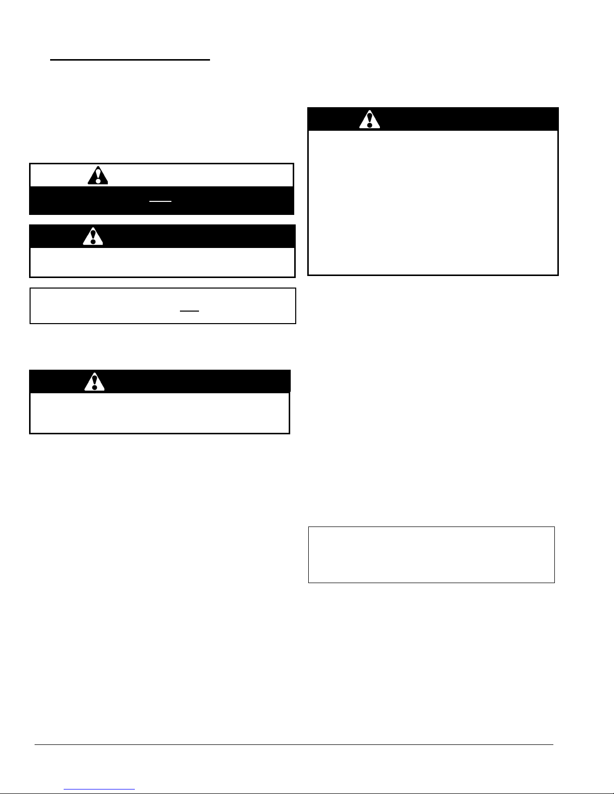
The unit can be installed in an enclosure such as a closet.
However, 2 ventilation openings are required for
combustion air. The openings should be located in front of
the furnace approximately 15 cm (6") above the floor and
15 cm (6") below the ceiling. Figure 1 indicates the
minimum dimensions required and the location of the
openings.
Figure 1: Location and dimensions of ventilation air
openings in a closet door
2.1 POSITIONING THE FURNACE
WARNING
Fire and explosion hazard.
The furnace must be installed in a level position, never
where it will slope toward the front.
Do not store or use gasoline or any other flammable
substances near the furnace.
Non-observance of these instructions will potentially result
in death, bodily injury and/or property damage.
CAUTION
This furnace is not watertight and is not designed for outdoor
installation. It must be installed in such a manner as to protect
its electrical components from water. Outdoor installation will
lead to a hazardous electrical condition and to premature
failure of the equipment.
The minimum clearances from combustible material for
each of the positions are specified in Table 9.
If the furnace is installed in a basement or on a dirt floor, in a
crawl space for example, it is recommended to install the unit
on a cement base 2.5 cm to 5.0 cm (1" to 2") thick.
2.2 CONFIGURATIONS
2.2.1 Upflow Installation
The return air opening may be located on either side of
the furnace. Care should be taken not to damage the
wires inside, while cutting the opening. Install the filter
rack supplied with the unit according to the instructions
provided with it. It is also recommended to install the
blower door before handling or moving the unit. Refer to
figure 2 for additional details.
Figure 2: Upflow installation
Burner position
Filter 20" x 20"
Combustible or noncombustible floor
5
Page 6
combustible
oor
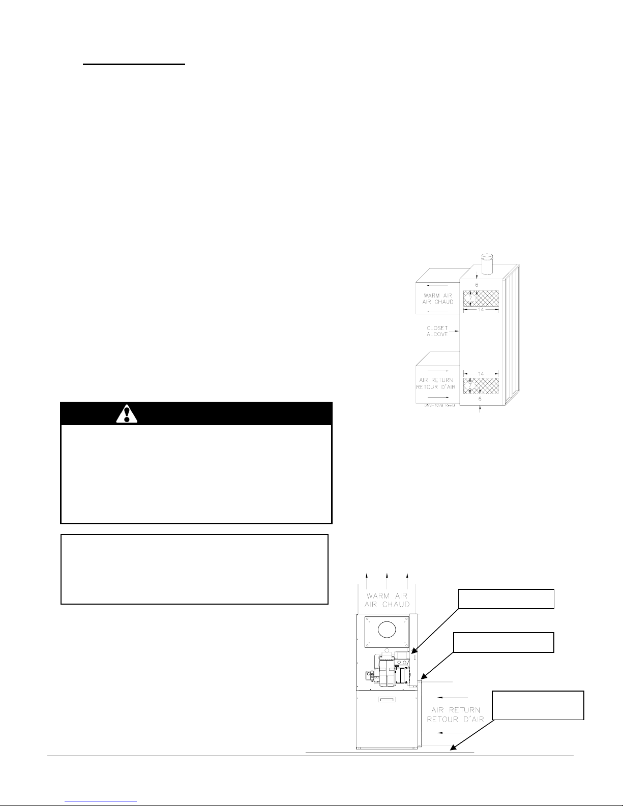
2.2.2 Downflow Installation
When the furnace is installed in the downflow position on a
combustible floor, the clearances from combustibles must be
adhered to. The downflow base DFB-102 or KLASB0801DET
can be used to ensure these clearances. Refer to Figure 3 and
the installation instructions provided with the base.
In cases where the return air enters through the floor, the floor
return base FRB-101 or KLARB0101DET must be used.
The burner must always be installed in the same manner,
regardless of the discharge position of the furnace. Refer to
Figure 3 for additional details.
Figure 3: Downflow installation
2.2.3 Horizontal Installation
When the furnace is installed in the horizontal position, either
suspended or on a combustible floor with a choice of right or
left discharge, the clearances from combustible material must
be adhered to. If the unit is installed on a combustible floor, the
horizontal floor base HFB-101 or KLASB0701DET can be
used to ensure these clearances. Refer to the instructions
supplied with the base.
In cases where the return air enters through the floor, the floor
return base FRB-101 or KLARB0101DET can be installed as
per the supplied instructions.
The burner must always be installed in the same manner,
regardless of the discharge position of the furnace. Refer to
Figure 4 for additional details.
Filter rack 20" x 20"
Floor Return Base
Burner position
Downflow base is
required for
combustible floor
Figure 4: Horizontal installation
Horizontal floor base
required for
fl
Floor Return
Filter rack 20" x 20"
2.3 ELECTRICAL SYSTEM
CAUTION
The exterior of the unit must have an uninterrupted ground
to minimize the risk of bodily harm, if ever an electrical
problem develops. A green ground screw is supplied with
the control box for that purpose.
The appliance must be installed in accordance with the
current ANSI/NFPA 70 National Electrical Code, CSA
C22.1 Canadian Electrical Code Part 1 and/or local codes.
The control system depends on the correct polarity of the
power supply. Connect “HOT” wire (H) and “NEUTRAL”
wire (N) as shown in figures 10 and 11.
A separate line voltage supply should be used, with fused
disconnect switch or circuit breaker, between the main
power panel and the unit.
Only copper wire may be used for the 115V circuit on this
unit. If wires need to be changed, the replacements must
have the same temperature resistance as the originals.
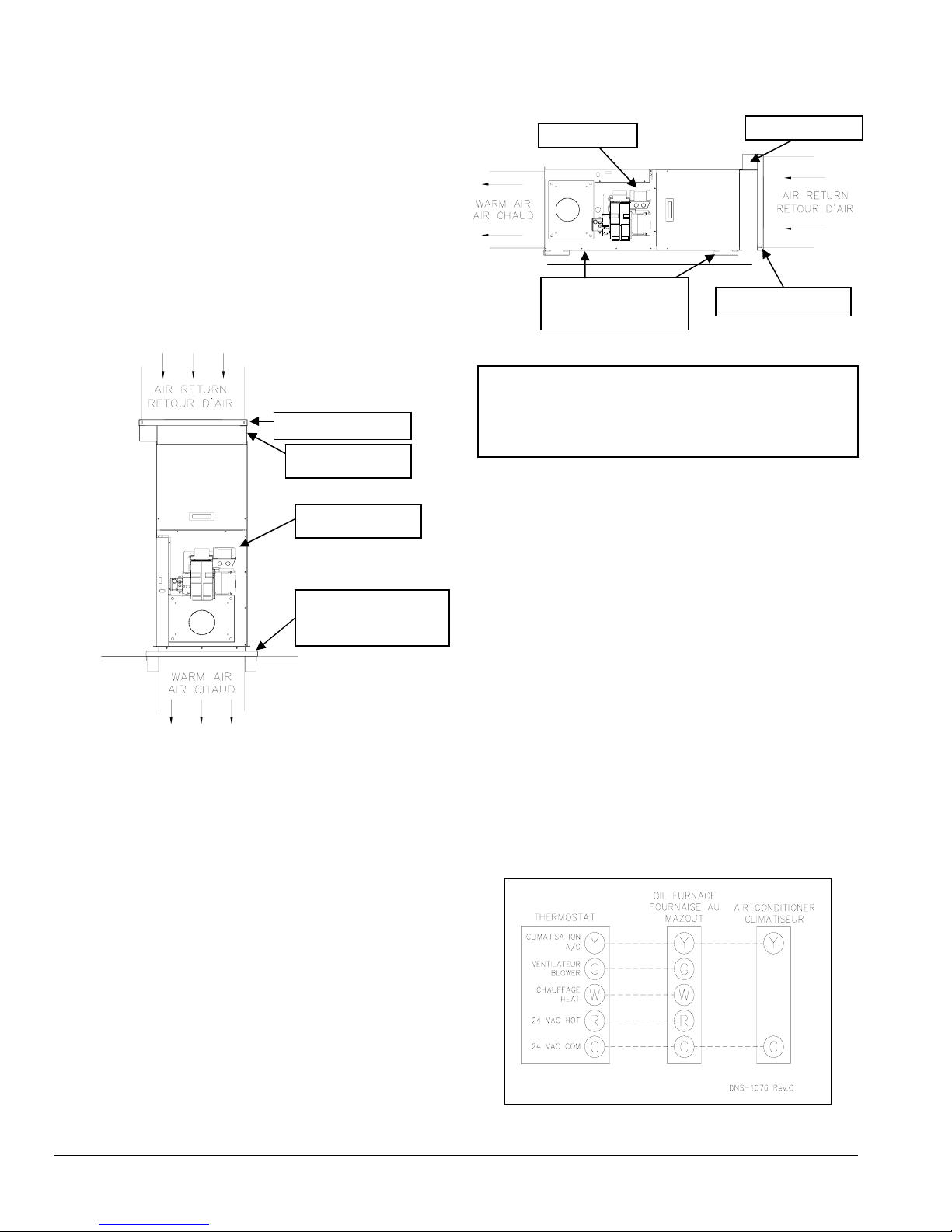
2.4 INSTALLATION OF THE THERMOSTAT
A thermostat must be installed to control the temperature
of the area to be heated. Follow the instructions supplied
with the thermostat. Also refer to the wiring diagrams
provided with the heating/air conditioning unit. The
connections must be made as indicated on the following
diagrams and the wiring diagrams, figures 10 and 11.
Figure 5: Thermostat wiring, heating and air
conditioning with 4-speed motor
6
Figure 6: Thermostat wiring heating and air
conditioning with ECM variable speed motor
Page 7
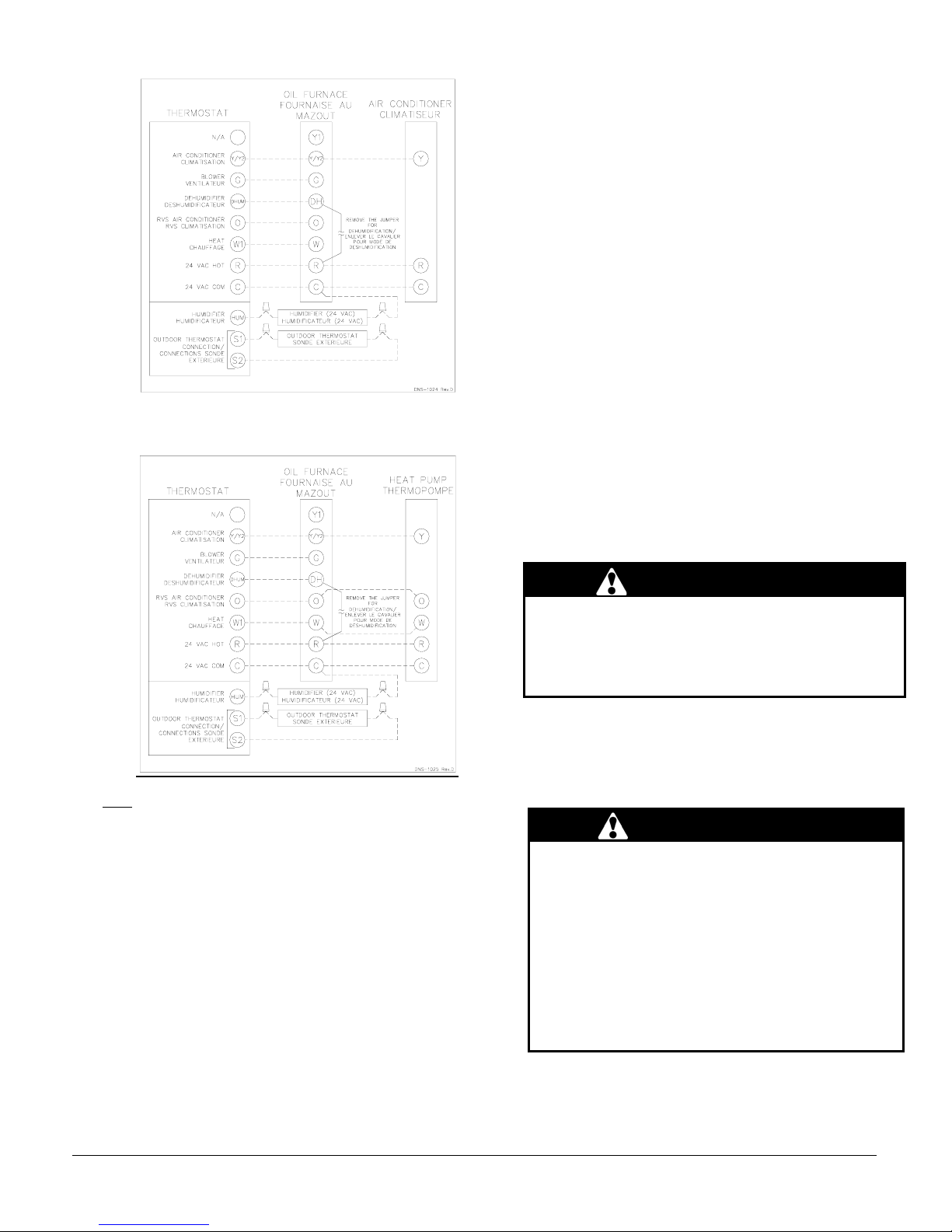
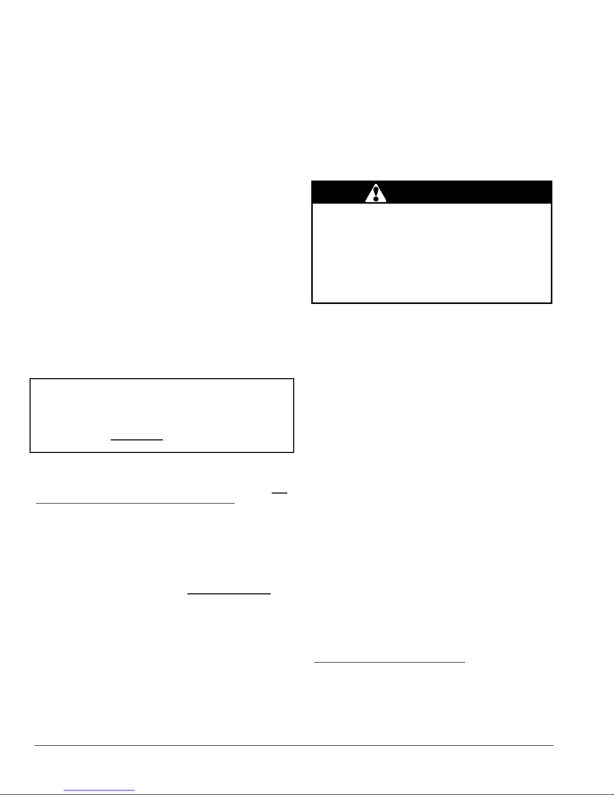
Figure 7: Thermostat wiring, heating and air cond. heat
pump with ECM v. speed motor
6. Complete oil line connections.
2.5.1 Nozzles
The burner comes equipped with an appropriate nozzle.
However, if another size or a replacement nozzle is
required, use the manufacturer’s recommended spray
angle and type a shown in Table 6 and based on a pump
pressure of 100 psi.
Always select nozzle sizes by working back from the
desired flow rate at operating pressure and not the nozzle
marking.
2.5.2 Air and Turbulator Settings
Before starting the burner for the first time, adjust the air
and turbulator settings to those listed in this manual, Table
6. Once the burner becomes operational, final
adjustments will be required. Refer to section 3 of this
manual.
2.5.3 Post purge delay adjustment
The post purge delay on the oil-fired burners is factory set
to zero second. This delay is applicable for all installations
with chimney venting. For heating units installed with side
wall venting and a burner equipped with this feature, the
post purge delay must be set to 15 seconds. Refer to the
burner control instruction manual and markings for proper
adjustment of the post purge delay.
Note: On units with 2 stage cooling or heat pump, terminal Y1
must be used. When Y1 on the electronic control receives a 24
VAC signal, the air flow is reduced by 20%. Do not use
terminal Y1 with a single stage cooling or heat pump.
2.5 INSTALLATION OF THE BURNER
Refer to the burner manufacturer’s instructions. Also, the
burner must be installed always in the same way
independently of the furnace orientation.
1. Position the mounting gasket between the mounting
flange and the burner mounting plate. Align the holes in
the burner mounting plate with the studs on the mounting
flange and bolt securely in place.
2. Remove the burner drawer assembly or the air tube
assembly;
3. Install the nozzle, refer to Technical Specifications Table
6;
4. Check the electrode settings;
5. Make the electrical connections;
2.6 VENTING
WARNING
Poisonous carbon monoxide gas, fire and explosion
hazard.
Read and follow all instructions in this section.
Failure to properly vent this furnace can result in in
death, bodily injury and/or property damage.
To ensure the safe and proper functioning of an oil
furnace, it must always be connected to a flue with
sufficient draft or to an approved side-wall venting system.
In addition, it is strongly recommended to perform a
complete inspection of all the existing venting systems.
WARNING
Poisonous carbon monoxide gas hazard.
Never install a hand operated damper in the vent pipe.
However, any Underwriters Laboratories listed,
electrically operated automatic type vent damper may
be installed if desired. Be sure to follow the
instructions provided with vent damper. Also, read
and follow all instructions in this section of the
manual.
Failure to properly vent this furnace or other
appliances can result in death, bodily injury and/or
property damage.
7
Page 8
2.6.1 Masonry chimney
This furnace can be vented into an existing masonry chimney.
However, the unit must not be vented into a chimney into
which a solid fuel burning furnace is already being vented.
Before venting this furnace into a chimney, its condition must
be checked and repairs made, if necessary. Also, the chimney
lining and dimensions must conform to local and national
codes.
2.6.2 Factory Built Chimneys
Oil fired furnaces are approved for use with “L” type vents. The
unit may also be used with an approved chimney of proper
dimensions and temperature ratings as specified in the
installation code. Refer to chimney manufacturer’s instructions
for proper installation.
2.6.3 Draft Regulator
It is recommended that a draft regulator be installed in cases
where the draft is either high or variable due to external
conditions. Follow the instructions provided with the regulator.
2.6.4 Side-wall Venting
The heating unit is approved for side-wall venting. This system
is comprised of a model VTK-098/KLAVT0101DET side-wall
venter and a 4” insulated vent pipe, model IFV09810/KLAFV0101DET, IFV098-20/KLAFV0201DET. Refer to the
installation instructions provided with the venting system.
2.7 BLOCKED VENT SHUT-OFF DEVICE
(BVSO) FOR CHIMNEY VENTING
CAUTION
It is imperative that this device be installed by a qualified service
technician.
A positive pressure venting system (Sealed Combustion System
or Direct Vent) MUST NOT use the BVSO. Follow the
instructions supplied with the venting system.
This device is designed to detect the insufficient evacuation of
combustion gases in the event of a vent blockage. In such a
case the thermal switch will shut down the oil burner. The
device will then need to be re-armed MANUALLY.
Refer to the detailed instructions and wiring diagrams supplied
with the BVSO for the installation and wiring procedures. The
length of wires supplied with the unit is such that the safety
device must be installed between the flue outlet of the
appliance and the draft regulator, as indicated in the
instructions.
It is also essential that the BVSO be maintained annually. For
more details refer to the instructions supplied with the device
itself, as well as Section 3. of this Manual.
2.7.1 BVSO Performance Test
The purpose of the following test is to check that the electrical
outlet on the furnace, designated to the BVSO, is functional.
1. Start up the burner;
2. Remove the three-pole plug from the BVSO outlet on
the furnace;
3. The burner must shut-off immediately, while the
blower continues to run to the end of the cool-down
cycle.
If the test is not in line with the above, call a QUALIFIED
SERVICE TECHNICIAN.
2.8 COMBUSTION AIR SUPPLY
VENTILATION
AND
WARNING
Poisonous carbon monoxide gas hazard.
Comply with NFPA 31 (U.S.) and CSA B139 (Canada)
standards for the installation of Oil Burning
Equipment and applicable provisions of local building
codes to provide combustion and ventilation air.
Failure to provide adequate combustion and
ventilation air can result in death, bodily injury and/or
property damage.
Oil furnaces must have an adequate supply of combustion
air. It is common practice to assume that older homes
have sufficient infiltration to accommodate the combustion
air requirement for the furnace. However, home
improvements such as new windows, doors, and weather
stripping have drastically reduced the volume of air
infiltration into the home.
Refer to oil furnace installation codes relative to
combustion and ventilation air requirements. Consult
Section 2.2 in this manual, specifically for units installed in
an enclosed space.
Home air exhausters are common. Bathroom and kitchen
fans, power vented clothes dryers and water heaters all
tend to create a negative pressure condition in the home.
Should this occur the chimney becomes less and less
effective and can easily downdraft. In certain cases,
mechanically supplied air, by way of a blower, interlocked
with the unit, is necessary. It is the installer’s responsibility
to check that.
2.8.1 Contaminated Combustion Air
Installations in certain areas or types of structures will
increase the exposure to chemicals or halogens that may
harm the furnace. These conditions will require that only
outside air be used for combustion.
The following areas or types of structures may contain or
be exposed to certain substances, potentially requiring
outside air for combustion:
a. Commercial buildings;
b. Buildings with indoor pools;
c. Furnaces installed near chemical storage areas.
Exposure to the following substances:
a. Permanent wave chemicals for hair;
b. Chlorinated waxes and cleaners;
c. Chlorine based swimming pool chemicals;
d. Water softening chemicals;
e. De-icing salts or chemicals;
f. Carbon tetrachloride;
8
Page 9
g. Halogen type refrigerants;
h. Cleaning solvents (such as perchloroethylene);
i. Printing inks, paint removers, varnishes, etc. ;
j. Hydrochloric acid;
k. Solvent based glue;
l. Antistatic fabric softeners for clothes dryers;
m. Acid based masonry cleaning materials.
2.8.2 Burner with Outdoor Combustion Air Kit
Certain burners are designed to function with combustion air
taken directly from the outside. Follow the instructions provided
with the burner, the fresh-air supply kit or the side-wall venting
kit.
2.9 OIL TANK
WARNING
Fire and explosion hazard.
Use only approved heating type oil in this furnace.
DO NOT USE waste oil, used motor oil, gasoline or
kerosene.
Use of these will result in death, bodily injury and/or
property damage.
CAUTION
When a 0.75 USGPH or smaller nozzle is used, a 10 micron or
finer filter, must be installed on the oil supply line to the
furnace inside the building where the unit is located.
This is a requirement in order for the heat exchanger warranty
to remain in force.
Check your local codes for the installation of the oil tank and
accessories.
At the beginning of each heating season or once a year, check
the complete oil distribution system for leaks.
Ensure that the tank is full of clean oil. Use No.1 or No.2
Heating Oil (ASTM D396 U.S.) or in Canada, use No.1 or No.2
Furnace Oil.
A manual shut-off valve and an oil filter shall be installed in
sequence from tank to burner. Be sure that the oil line is clean
before connecting to the burner. The oil line should be
protected to eliminate any possible damage. Installations
where the oil tank is below the burner level must employ a twopipe fuel supply system with an appropriate fuel pump. A rise
of 2.4 m (8') and more requires a two stage pump and a rise
greater than 4.9 m (16') an auxiliary pump. Follow the pump
instructions to determine the size of pipe needed in relation to
the rise or to the horizontal distance.
2.10 DUCTING
WARNING
Poisonous carbon monoxide gas hazard.
DO NOT draw return air from inside a closet or utility
room. Return air MUST be sealed to the furnace
casing.
Failure to properly seal ducts can result in death,
bodily injury and/or property damage.
The ducting must be designed and installed according to
approved methods, local and national codes as well as
good trade practices.
When ducting supplies air to a space other than where the
furnace is located, the return air must be sealed and also
be directed to the space other than where the furnace is
located.
2.10.1 Air filter
A properly sized air filter must be installed on the return air
side of the unit. Refer to the Technical Specifications,
table 6, for the correct dimensions. Also refer to Section
2.2 and the instructions supplied with the filter.
2.11 SUPPLY AIR ADJUSTMENTS
SPEED MOTORS)
(4
On units equipped with 4-speed blower motors, the supply
air must be adjusted based on heating/air conditioning
output and the static pressure of the duct system. For the
desired air flow refer to the following table as well as the
air flow tables based on static pressure in the Technical
Specifications, table 6, of this manual.
Table 1: Blower speed adjustments (4-speed motors)
FURNACE
APPLICATION
HEATING
A/C
To effect the adjustment, the RED (for heating) and BLUE
(for cooling and heat pump) wires can be changed on the
motor. Also, refer to the position of the wires on the
electronic board of the unit and consult the wiring
diagrams. If the heating and air conditioning speeds are
the same, the RED wire must be moved to “UNUSED
LEADS” on the electronic board and the jumper provided
with the BLUE wire must be used between the “HEAT”
and “COOL” terminals.
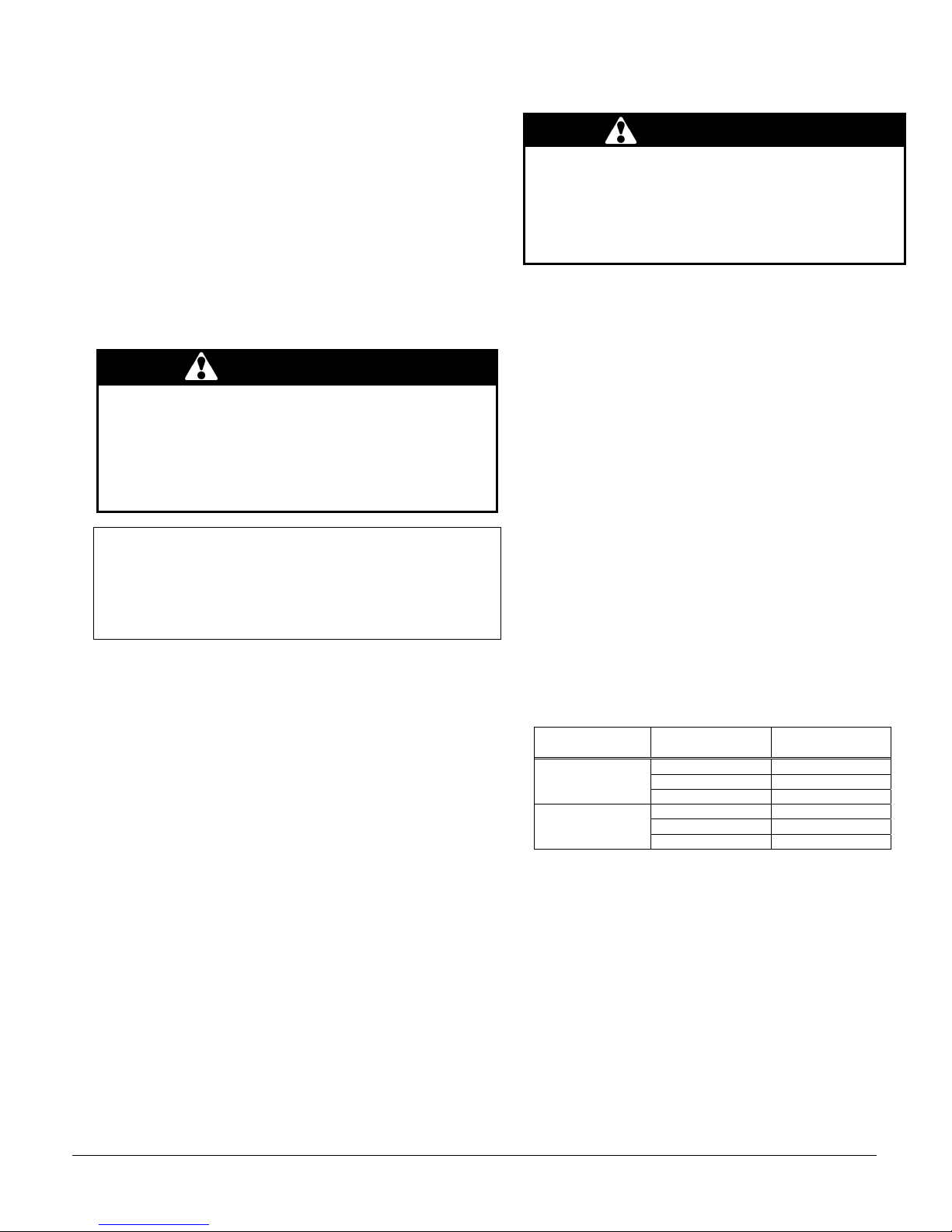
The blower start/stop delays can be adjusted by
positioning the DIP switches on the electronic board as
shown in the following figures. The recommended blower
ON delay is 60 seconds and the blower OFF delay is 2
minutes.
HEATING OR A/C
OUTPUT
0.50 USGPH MED-LOW
0.60 USGPH MED-HIGH
0.70 USGPH HIGH
2.0 TONS MED-LOW
2.5 TONS MED-HIGH
3.0 TONS HIGH
RECOMMENDED
BLOWER SPEED
9
Page 10
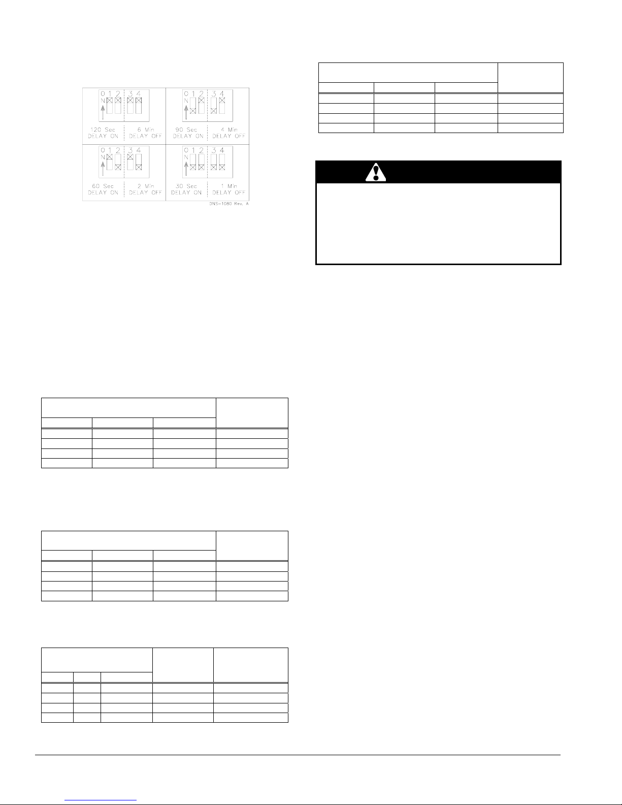
Figure 8: Blower start/stop delays
Board # 1158
2.12 SUPPLY AIR ADJUSTMENTS
VARIABLE SPEED MOTORS)
(ECM
On units equipped with ECM variable speed blower motors,
the air supply must be adjusted based on heating/air
conditioning output. The start/stop delays of the blower must
also be adjusted by positioning the DIP switches on the
electronic board. Refer to the following tables, air flow table 2
and the wiring diagram, figures 10 and 11 in this manual for
the proper settings:
Table 2: Supply air adjustments, ECM variable speed
motors, heating mode
1 2 POSITION
OFF OFF A 0.70
ON OFF B 0.60
OFF ON C 0.50
ON ON D ALL
Table 3: Supply air adjustments, ECM variable speed
1 2 POSITION
OFF OFF A 3.0
ON OFF B 2.5
OFF ON C 2.0
ON ON D 1.5
SW1 – HEAT
DIP Switch Positions
USGPH
motors, air conditioning mode
SW2 – COOL
DIP Switch Positions
Table 4: CFM adjustments, all modes
Input
Output
Tons
Table 5: Delay adjustments - heating mode
SW4 – Delay
DIP Switch Positions
1 2 POSITION
OFF OFF A 0.70
ON OFF B 0.60
OFF ON C 0.50
ON ON D ALL
Input
USGPH
2.13 INSTALLATION OF ACCESSORIES
WARNING
Electrical shock hazard.
Turn OFF electrical power at the fuse b ox or service
panel before making any electrical connections and
ensure a proper ground connection is made before
connecting line voltage.
Failure to do so can result in death or bodily injury.
2.13.1 Humidifier (HUM)
The 120 VAC HUM terminal on the electronic board of the
blower is tied directly to terminal 8 of the 9-terminal
connector of the electronic board. It supplies 120 VAC
electric power when the burner is in operation.
A 24 VAC signal can also be supplied from the W and C
terminals on the blower electronic board to activate a
switching relay.
Also refer to the instructions supplied with the accessory.
2.13.2 Electronic Air Cleaner (EAC)
The EAC terminal on the electronic board supplies 120
VAC when the blower is operating in the heating or air
conditioning mode. This signal can be used to activate an
electronic air cleaner that is not equipped with an air flow
switch. If the cleaner is equipped with an air flow switch,
the S terminal on the electronic board or one of the 120
VAC terminal on the ECM electronic card can be used to
provide a constant supply of 120 VAC.
Also refer to the instructions supplied with the accessory.
SW3 – ADJ (Adjustment)
DIP Switch Positions
1 2 POSITION
OFF OFF A 0% 0%
ON OFF B +10% +10%
OFF ON C -10% -10%
ON ON D N/A 0%
10
CFM HTG.
% increase
or decrease
CFM A/C
% increase
or decrease
Page 11

2.13.3 Air Conditioner (or Heat Pump)
An air conditioning coil may be installed on the supply air side
ONLY.
WARNING
Poisonous carbon monoxide gas hazard.
Install the evaporator coil on the supply side of the
furnace ducting ONLY.
An evaporator coil installed on the return air side of the
ducting can cause condensation to form inside the heat
exchanger, resulting in heat exchanger failure. This in
turn, can result in death, bodily injury and/or property
damage.
A clearance of 15 cm (6") is required between the bottom of
the coil drain pan and the top of the heat exchanger. If a heat
pump is installed, a “dual-energy” thermostat, or other control
is recommended, in order to prevent the simultaneous
operation of the furnace and the heat pump. It also prevents a
direct transition from heating by way of the heat pump to
heating with oil. Refer to the thermostat instructions or those of
another control used for the proper wiring.
3 OPERATION
3.2 OPERATING SEQUENCE
HEATING MODE
OIL
1. The W-R contact closes;
2. The burner motor starts up to pre-purge the
combustion chamber for a period of 10 to 15
seconds. During that time a spark is established on
the electrodes;
3. The solenoid valve opens and a flame is established.
Shortly after, the electrodes cease to spark;
4. Then the blower runs up to full speed. The delay
depends on the adjustments that were made on the
electronic board, which controls the blower motor.
Refer to Sections 2.11 and 2.12, as well as the CFM
table 7 for more details.
5. When the call for heat is satisfied, the solenoid valve
closes, the flame goes out and the burner motor
stops (after post purge delay, if applicable).
6. The blower stops shortly after the burner. The delay
depends on the adjustments that were made on the
electronic board that controls the blower. Refer to
Sections 2.11 and 2.12, as well as the CFM table 7
for more details.
Note: A detailed operating sequence of the oil burner is
outlined in the instructions provided with the burner.
3.3 CHECKS AND ADJUSTMENTS
3.1 START-UP
Before starting up the unit, be sure to check that the following
items are in compliance:
1. The electrical installation, the oil supply system, the
venting system, combustion air supply and ventilation;
2. The blower access door is in place and the blower rail
locking screws are well tightened;
3. The Blocked Vent Shut-Off (BVSO) is installed according
to instructions (for chimney venting);
4. The oil supply valve is open;
5. The burner ‘’Reset’’ button is well pushed in or re-armed;
6. The preliminary air adjustments on the burner comply
with the technical specifications in this manual;
7. The blower speed adjustments for heating and air
conditioning are appropriate and according to the
specifications in this manual;
8. The blower start/stop delays are satisfactory;
9. The thermostat of the room is in the heating mode and is
set higher than the ambient temperature.
To start the unit, turn the main electrical switch on.
3.3.1 Purging the oil line
Open the bleed port screw and start the burner. Allow the
oil to drain into a container for at least 10 seconds. The oil
should flow absolutely free of white streaks or air bubbles
to indicate that no air is being drawn into the suction side
of the oil piping and pump. Slowly close and tighten the
bleed screw. Once closed, the flame will light up.
3.3.2 Pressure adjustment
The oil pressure must be adjusted according to the
Technical Specifications of this manual. An adjustment
screw and a connection for a pressure gauge are located
on the oil pump for that purpose. Also refer to the burner
instruction manual.
11
Page 12

3.3.3 Combustion Check
IMPORTANT
The heat exchanger metal surfaces may have oil and the
baffle insulation also contains binders. These products will
burn or evaporate when the unit operates for the first time.
Because of that, the smoke reading may be skewed during the
first minutes of operation. Therefore, the unit must operate
during at least 60 minutes before taking any readings to adjust
the combustion quality. Let the unit cool down before making
any adjustments.
IMPORTANT
The combustion check verification MUST be performed after
the nozzle replacement or the burner cleaning. After these
manipulations, the combustion parameters are necessarily
modified. Refer also to the burner instruction manual.
1. Pierce a test hole in the flue pipe, approximately 18 inches
from the furnace breech. Insert the smoke test probe into
the hole. For installation using a sidewall venting, use the
orifice provided on the breech plate;
2. From a cold start, let the unit operate for about 5 minutes;
3. Set the burner air setting until you have between 0 and 1
on the Bacharach Scale (or a ‘’trace’’);
4. Take a CO
#1 smoke reading was taken and make note of it.
Example: 13.8% of CO
5. Adjust the burner air setting to obtain a CO
lower (or a O
associated with the ‘’trace’’ of smoke. Example: 12.3% of
CO
or 4.5% of O2;
2
6. This method of adjusting the burner will result in clean
combustion (Bacharach smoke scale between 0 and a
‘’trace’’) and ensure the proper functioning of the system.
The optimum CO
5.0% of O
3.3.4 Draft Regulator adjustment
On chimney installations only, a barometric draft regulator
(supplied with the furnace) must be installed, in order to ensure
proper draft through the furnace. The barometric damper must
be mounted with the hinge pins in a horizontal position and the
face of the damper vertical for proper functioning (see
instructions included with the damper.) After the furnace has
been firing for at least five minutes, the draft regulator should
be set to between -0.025" and -0.060" W.C.
3.3.5
Overfire pressure test
The overfire draft that is taken through the observation port,
located above the burner, is a measurement necessary to
determine if there is a blockage in the heat exchanger or the
flue pipe. Refer to the Technical Specifications in this manual
for overfire pressure values. A high pressure condition may be
caused by excessive combustion air, due to the air band being
too wide open, or a lack of flue draft (chimney effect) or some
other blockage, such as soot in the secondary section of the
heat exchanger or the use of an oversize nozzle input or high
pressure pump.
3.3.6 Vent Temperature Test
1. After having adjusted the burner combustion, insert a
thermometer into the test hole in the breech pipe;
sample at the same test location where the
2
or 2.5% of O2;
2
reading 1.5%
reading 2.0% higher) than the reading
2
level is around 12% to 13% (or 3.5% to
2
).
2
2
2. The total vent temperature should be between 204
and 302°C (400 and 575°F). If not, check for improper
air temperature rise, pump pressure, nozzle size or a
badly sooted heat exchanger.
CAUTION
Low flue gas temperatures increase the risk of
condensation. Adjust the total
temperature at or higher
then 204°C (400°F) in order for the heat exchanger
warranty to remain in force.
3.3.7 Supply Air Temperature Rise Test
1. Operate the burner for at least 10 minutes;
2. Measure the air temperature in the return air plenum;
3. Measuring the air temperature in the largest trunk
coming off the supply air plenum, just outside the
range of radiant heat from the heat exchanger. 0.3 m
(12") from the plenum of the main take-off is usually
sufficient;
4. The temperature rise is calculated by subtracting the
return air temperature from the supply air
temperature;
5. If the temperature rise is lower or exceeds the
temperature specified in Table 6, change to the next
lower or higher blower speed tap, until the
temperature rise falls to the target. If the excessive
temperature rise cannot be increased or reduced by
changing fan speed, investigate for ductwork
obstructions, dirty or improper air filter, improper firing
caused by improper pump pressure or nozzle sizing.
3.3.8 Limit Control Check
After operating the furnace for at least 15 minutes, restrict
the return air supply by blocking the filters or the return air
register and allow the furnace to shut off on High Limit.
The burner will shut off but the blower will continue to run.
Remove the obstruction and the burner should restart
after a few minutes. The time required for the restart also
depends on the adjustment of the blower “OFF” delay.
3.3.9 Restart after Burner Failure
1. Set the thermostat lower than room temperature;
2. Press the reset button on the burner primary control
(relay);
3. Set the thermostat higher than room temperature;
4. If the burner motor does not start or ignition fails, turn
off the disconnect switch and CALL A QUALIFIED
SERVICE TECHNICIAN.
CAUTION
Do not attempt to start the burner when excess oil has
accumulated, when the furnace is full of vapour or when
the combustion chamber is hot.
12
Page 13
4 MAINTENANCE
WARNING
Electrical shock hazard.
Turn OFF power and fuel to the furnace before any
disassembly or servicing.
Failure to do so can result in death, bodily injury and/or
property damage.
Preventive maintenance is the best way to avoid unnecessary
expense and inconvenience. Have your heating system and
burner inspected by a qualified service technician at regular
intervals.
To maintain the reliability and optimal performance of the
furnace, have a complete combustion check done after the
annual maintenance call. Do not attempt to repair the furnace
or its controls. Call a qualified service technician.
Before calling for repair service check the following points:
1. Check the oil tank gauge and make sure that the valve is
open;
2. Check fuses and the circuit breaker;
3. Check if the main disconnect switch is ON ;
4. Set the thermostat above room temperature;
5. If ignition does not occur, turn off the disconnect switch
and call a qualified service technician.
When ordering replacement parts, please specify the
complete furnace model number and serial number.
4.1 CLEANING THE HEAT EXCHANGER
It is not generally necessary to clean the heat exchanger or
flue pipe every year, but it is advisable to have the oil burner
service technician check the unit before each heating season
to determine whether the cleaning or replacement of parts is
necessary.
If a cleaning is necessary, the following steps should be
performed:
1. Turn OFF all utilities upstream from the furnace;
2. Disconnect the flue pipe;
3. Remove the flue collar panel located at the front of the
furnace;
4. Remove the heat exchanger baffles;
5. Disconnect the oil line and remove the oil burner;
6. Clean the secondary tubes and the primary cylinder with a
stiff brush and a vacuum cleaner;
7. Before re-assembling the unit, the heat exchanger and
combustion chamber should be inspected to determine if
replacement is required;
8. After the cleaning replace the heat exchanger baffles, flue
collar plate and oil burner;
9. Readjust the burner for proper operation.
13
4.2 CLEANING THE BLOCKED VENT
SHUT-OFF
For continuous safe operation, the Blocked Vent Shut-off
device (BVSO) must be inspected and maintained annually
by a qualified service technician.
1. Disconnect power to the appliance;
2. Remove the two screws holding on the BVSO
assembly cover;
3. Remove the cover;
4. Remove the two screws holding the control box to the
heat transfer tube assembly. Sliding the control box in
the appropriate direction will unlock it from the heat
transfer tube assembly;
5. Carefully remove any build-up from the thermal switch
surface;
DEVICE (BVSO)
CAUTION
Do not dent or scratch the surface of the thermal switch. If
the thermal switch is damaged it MUST be replaced.
6. Clean and remove any build-up or obstruction inside
the heat transfer tube;
7. Re-mount, lock and fasten the control box with the 2
screws removed in step 4;
8. Re-attach the assembly cover with the screws removed
in step 2;
9. Re-establish power to the unit.
4.3 CLEANING OF THE BURNER HEAD
Once annually, remove the retention head and electrodes
from the drawer assembly and remove all foreign matter, if
necessary. Also clean the extremity of the burner tube, if
necessary.
4.4 CHANGING THE NOZZLE
Change the nozzle once a year with the one specified in
Table 6.
4.5 CHANGING THE OIL FILTER
Tank Filter
The tank filter should be changed as required. Follow the
manufacturer’s instructions.
Secondary Filter
The 10 micron, or finer, filter cartridge should be changed
annually. Follow the manufacturer’s instructions.
4.6 CHANGING THE AIR FILTER
Dirty filters have an impact on the efficiency of the furnace
and increase fuel consumption.
Air filters should be changed at least once a year. Very
dusty conditions, the presence of animal hair and the like
will require more frequent changing or cleaning.
Page 14

5 FURNACE INFORMATION
Model:
Furnace installation date:
Service telephone #-Day:
Dealer name and address:
START-UP RESULTS
Nozzle:
Burner adjustments:
:
CO
2
Gross stack temperature:
Ambient temperature:
Chimney draft :
Overfire draft :
Test performed by:
Primary air
Fine air
Drawer Assembly
% Smoke scale:
Serial number:
Night:
Pressure:
°F
°F
" W.C.
" W.C.
(Bacharach)
Lb/in
2
14
Page 15
p
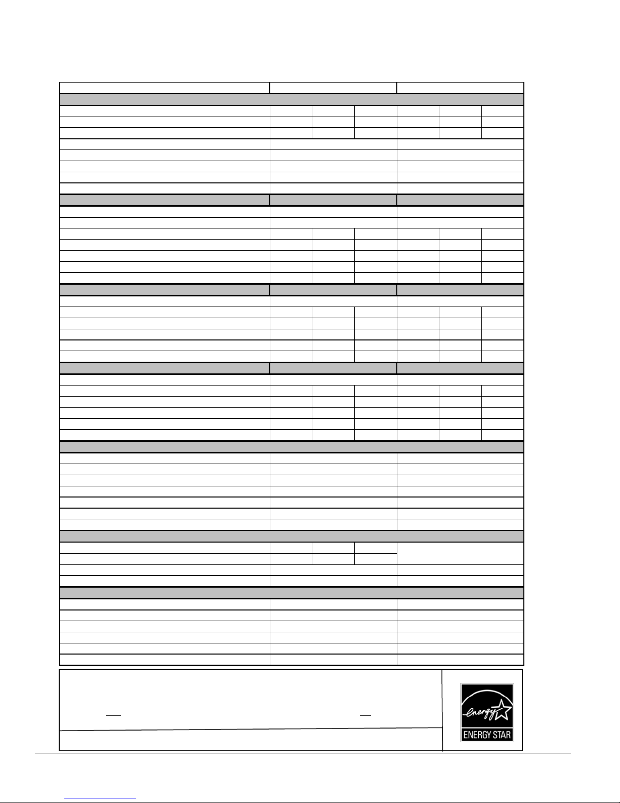
Table 6: Technical specifications
MULTI POSITIONS MODELS - SERIE S 098
RATI NG AND PERFORMANCE
Firing rate (USGP H)* 0,50 0,60 0,70 0,50 0,60 0.70
Input (BTU/h)* 70 000 84 000 98 000 70 000 84 000 98 000
M axim um H eating capacity, (BTU/h)* 59 200 70 400 80 800 59 200 70 400 80 800
Heating temperature rise (Degr. F)*
Flue draft with chimney (inch of w.c.)
Overfire pressure with chim ney (inch of w .c.)
Flue pressure with direct vent (inch of w.c.)
Overfire pressure with direct vent (inch of w .c.)
BECKETT BURNER; MODEL NX ( Chi mne y or DV)
Burner tube insertion length (inches)
H e a d type
Nozzle (Delavan) 0.40 - 60A 0.50 60A 0.60 - 60A 0.40 - 60A 0.50 - 60A 0.60 - 60A
M inimum and Maximum pump pressure (PSI G)* 155 145 135 155 145 135
H e a d /Air settin g 0,5 1,5 2,5 0,5 1,5 2,5
AFU E % (From CSA B212 standard and C anadian regulation)** 85.0 ‡ 84,2 81,9 85.0 ‡ 84,2 81,9
AFU E % (From ASHRAE 103 standard and US regulation)** 85.0 ‡ 83,9 81,9
RIELLO BURNER; MODEL 40-F3 ( Chi mne y)
Burner tube insertion length (inches)
Nozzle (Delavan) 0.40 - 70A 0.50 - 70A 0.60 - 70A 0.40 - 70A 0.50 - 70A 0.60 - 70A
M inimum and Maximum pump pressure (PSI G)* 155 145 135 155 145 135
C o mbustion a ir ad j u stmen t (turbu l a tor/d amper) 0 / 1.5 0 / 2.5 1 / 3.5 0 / 1 .5 0 / 2.5 1 / 3.5
AFU E % (From CSA B212 standard and C anadian regulation)** 85.0 ‡ 84,2 81,9 85.0 ‡ 84,2 81,9
AFU E % (From ASHRAE 103 standard and US regulation)** 85.0 ‡ 83,9 81,9
RIELLO BURNER; M ODEL 40- BF3 ( Dire ct ve nt DV)
Burner tube insertion length (inches)
Nozzle (Delavan) 0.40 - 70A 0.50 - 70A 0.60 - 70A 0.40 - 70A 0.50 - 70A 0.60 - 70A
M inimum and Maximum pump pressure (PSI G)* 155 145 135 155 145 135
Combustion air adjustment (turbulator/damper) 0 / 3.25 0 / 4 1 / 5.25 0 / 3.25 0 / 4 1 / 5.25
AFU E % (From CSA B212 standard and C anadian regulation)** 85.0 ‡ 84,2 81,9 85.0 ‡ 84,2 81,9
AFU E % (From ASHRAE 103 standard and US regulation)** 85.0 ‡ 83,9 81,9
ELE CTRICAL SYSTEM
Vol t s - Hertz - Phase
Rated current (Amps)
M inimum ampacity for wire sizing (Amps)
Max. fuse si ze (Amps)
Con trol transformer (VA)
E xternal control power available Heating (VA)
Co o l in g (VA)
BLOWER DATA
Heating blower speed at 0.25" W.C. SP M ED -LOW MED -H I GH HIGH
Heating blower speed at 0.50" W.C. SP M ED -LOW MED -H I GH HIGH
M otor (HP) / num ber of speeds
Blower size (diam. x w idth)
GENERAL INFORMATION
Overall dimensions (w idth x depth x height)
Supply air opening (w idth x depth)
Return air opening (width x depth)
Filter size (depth x hieght x thickness)
Shipping weight Lbs/Kg
Air conditioning, maximum output (tons) at 0.5 SP
U NITS WITH 1 /3 HP PSC MOTO R UNITS WITH 1 /2 HP ECM MO TOR
55 - 85 Degr. F 55 - 85 Degr. F
-0.06 to -0.0 2 5 -0.06 to -0.0 2 5
-0.035 to + 0 .0 1 0
+0 .0 5 to +0.20 +0 .0 5 to +0.20
+0.03 to +0.15
NX56LQ NX56LQ
1 3/4'' 1 3/4''
6 - Slot LQ head 6 - Slot LQ head
F3 WITH A IR IN LET DAMPER F3 WITH AIR INLE T DAMP ER
2 3/4'' 2 3/4''
BF3 BF3
2 3/4'' 2 3/4''
115 - 60 - 1 115 - 60 - 1
12.2
13.7 12.2
15 15
40 40
40 40
30 30
1/3 HP / 4 speeds 1/2 HP / E CM
10'' x 8'' 10'' x 8''
16.875'' x 20 1/8'' x 40 3/4'' 16.875'' x 20 1/8'' x 40 3/4''
16'' x 19'' 16'' x 19''
19'' x 19'' 19'' x 19''
20'' x 20'' 20'' x 20''
125 / 57 125 / 57
2,5 3.0
-0.035 to + 0 .0 1 0
+0 .0 3 to +0.15
85.0 ‡
85.0 ‡
85.0 ‡
83,9 81,9
83,9 81,9
83,9 81,9
10.3
See the ECM air flow table
* INPUT & OUTPUT ADJUSTMENT
Pump pressure can be adjusted to maintain proper firing rate. ‡ =
Increase pump pressure if flue gases temperature is under 400˚F
Adjust the total
Adjust fan speed for air temperature rise of 55˚ to 85˚F.
** AFUE value established after minimum 20 hours of o
flue gas temperature between 400˚F and 575˚F (330˚F and 505˚F net approximately)
eration.
15
Page 16
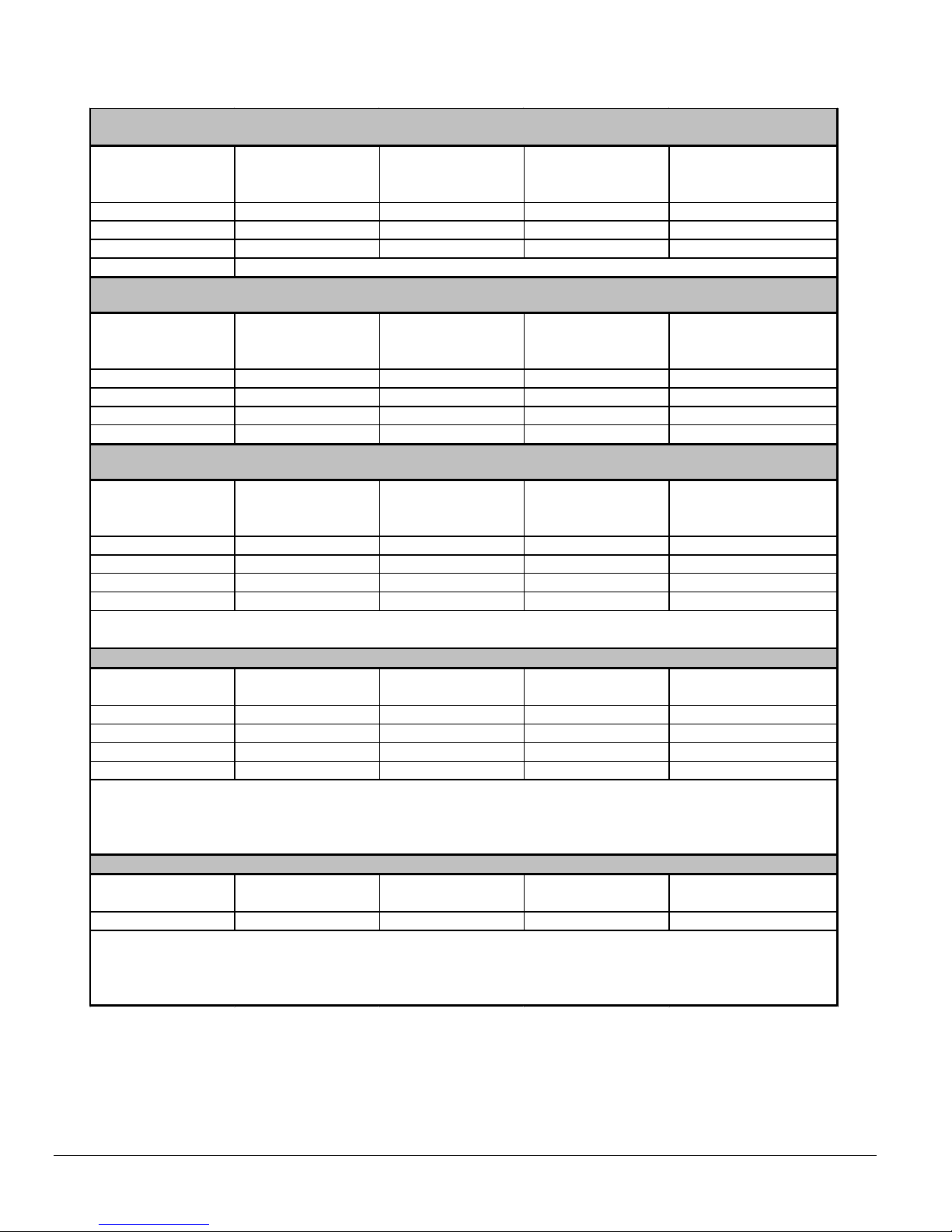
Table 7: Airflow data, models with 1/2 HP ECM motors
OIL HEATING MODE
24 VA C input (R) on W onl y
SW1- HEAT
DIP switch position
A
(1= OFF, 2=OFF)
B
(1=ON, 2=OFF)
C
(1=OFF, 2=ON)
D
(1=ON, 2=ON)
HEA T INPUT
(USGPH)
CFM with SW3-ADJ
DIP switc h position A
CFM wi th SW3 -ADJ
DIP swi t ch pos i t i on B
CFM with SW 3-ADJ
DIP switc h position C
0,70 1260 1385 1135
0,60 1050 1155 945
0,50 850 935 765
Sam e value as DIP switc h pos i t i on A
CONTI NUO US F AN
24 VA C input (R) on G only
SW2- COOL
DIP switch position
A
(1= OFF, 2=OFF)
B
(1=ON, 2=OFF)
C
(1=OFF, 2=ON)
D
(1=ON, 2=ON)
A/C size
(TON)
CFM with SW3-ADJ
DIP switc h position A
CFM wi th SW3 -ADJ
DIP swi t ch pos i t i on B
CFM with SW 3-ADJ
DIP switc h position C
3,0 900 1035 765
2,5 750 860 635
2,0 600 690 510
1,5 450 515 380
COOLING O R HEAT PUMP HEATI NG M O DE
24 VA C input (R) to G, Y / Y2 and O (for cooli ng)
SW2- COOL
DIP switch position
A
(1= OFF, 2=OFF)
B
(1=ON, 2=OFF)
C
(1=OFF, 2=ON)
D
(1=ON, 2=ON)
A/C size
(TON)
CFM with SW3-ADJ
DIP switc h position A
CFM wi th SW3 -ADJ
DIP swi t ch pos i t i on B
CFM with SW 3-ADJ
DIP switc h position C
3,0 1200 1320 1080
2,5 1000 1100 900
2,0 800 880 720
1,5 600 660 540
In Cooling - Dehumidific ation m ode, wit h no 24 VAC i nput to DH, the CFM s are reduced by 15% .
The CFMs shown are reduced by 20% i f there i s 24 VAC input to Y 1 (firs t st age of 2-stage c ool ing uni t)
DELAY PROFILE FOR OIL HEATING MODE
SW4- DELA Y
DIP switch position
A
(1= OFF, 2=OFF)
B
(1=ON, 2=OFF)
C
(1=OFF, 2=ON)
D
(1=ON, 2=ON)
HEA T INPUT
(USGPH)
PreRun On-Delay
CFM Level - Time
Short Run On-Delay
CFM Level - Time
Off-Delay
CFM Level - Tim e
0,75 13% - 45 sec . 19% - 30 sec 38% - 3 mi n.
0,65 13% - 45 sec . 19% - 60 sec 38% - 3 mi n.
0,50 13% - 60 sec . 13% - 60 sec 38% - 3 mi n.
All 13% - 30 sec . 100% - 30 sec 100% - 2 min.
PreRun and Short Run are t he peri ods of t i m e when t he bl ower s t art s at very low CFM t o m i nimize t he
distribution of cool air in the system and then runs up to normal s peed.
Off Delay is the t im e requi red t o cool down t he heat ex changer wit h low CF M s , t o m i nimize c ool draft in the
air distribution system.
DELAY PR OFI L E F O R CO O L ING O R HEAT PUM P HEATING MODE
No adjustment
required
A/C size
PreRun On-Delay
CFM Level - Time
Short Run On-Delay
CFM Level - Time
Off-Delay
CFM Level - Tim e
- All No delay No delay 100% - 90 s ec .
PreRun and Short Run are t he peri ods of t i m e when t he bl ower s t art s at very low CFM t o m i nimize t he
distribution of cool air in the system and then runs up to normal s peed.
Off Delay is the t im e requi red t o cool down t he coil (heat i ng m ode) wit h low CFM s, to mi ni m i z e cool draft
in the air distribution system.
16
Page 17

Table 8: Airflow data, models with 1/3 HP PSC motors
Speed
HIGH
MED-HIGH
MED-LOW
LOW
External Static Press ure ("W.C.)
0,10,20,30,40,50,60,70,80,9
1230 1185 1150 1095 1050 990 920 810 595
1090 1055 1005 970 925 875 810 700 550
865 860 860 845 795 740 695 600 460
675 680 690 680 665 640 565 480 390
Table 9: Minimum clearances from combustible materials
SIDE S
BOTTOM
BACK
TOP
FLUE PIPE
FRONT
LOCATION
FURNACE
PLENUM AND WARM-AIR DUCT WITHIN 6 f t. OF FURNACE
FURNACE
FURNACE (OPPOSITE SIDE OF THE BURNER)
PLENUM OR HORIZONTAL WARM-AIR DUCT WITHIN 6 f t. OF FURNACE
FURNACE
AROUND FLUE PIPE 22.86 cm (9") 22.86 cm (9") 22.86 cm (9")
FURNACE (BURNER SIDE)
1
These are horizontal dim ensions
2
These are vertical dimensions
3
Thi s dimension can be obtained by using Horizontal Flow Base # HFB-101 or KLASB0701DET
4
Thi s dimension can be obtained by using Downflow Base # DFB-102 ro KLASB0801DET
1
1
2
1
2
2
1
UPFLOW HORIZONTAL DOWNFLOW
2.54 cm (1") N/A 2.54 cm (1")
5.08 cm (2") 2.54 cm (1") 5.08 cm (2")
Ø2.54 cm (1")35.08 cm (2")
7.62 cm (3") 2.54 cm (1") 7.62 cm (3")
5.08 cm (2") 5.08 cm (2") 5.08 cm (2")
N/A 5.08 cm (2") N/A
45.72 cm (18") 45.72 cm (18") 45.72 cm (18")
4
17
Page 18

Figure 9: Furnace dimensions
18
Page 19

Figure 10: Wiring diagram, 4-speed motor (PSC)
19
Page 20

Figure 11: Wiring diagram, variable speed motor (ECM)
20
Page 21

COMPONENTS
AND
REPLACEMENT PARTS
21
Page 22

Figure 12: Parts list with 4-speed motor (PSC)
B50064G
22
Page 23

B50064H
Table 10: Parts list with 4-speed motor (PSC)
ITEM PART # DESCRIPTION COMMENTS
1 B03409 HEAT EXCHANGER Heat exchanger only
2 J06L002 SEAL STRIP, 1/4 x 1/8 x 25'
3 B03429 WIRE CHANNEL, INT.
4 B03420-01 FRONT PANEL ASSEMBLY Panel, insulation and labels included
5 B03444 FRONT PANEL INSULATION
6 B03450-01 BAFFLE, LATERAL
7 B03426-01 SIDE PANEL ASSEMBLY (RIGHT) Panel, insulation and baffl e included
8 B03473 SIDE PANEL INSULATION
9 L04J001 CABLE CLAMP, 9/16" WHITE
10 F06F015 WASHER, ZINC 1 7/16"
11 Z99F061 OBSERVATION PORT
12 L04I013 STRAIN RELIEF BUSHING
13 B03448 WIRE CHANNEL (BVSO/SWITCH)
14 B03455-01 ELECTRICAL KIT, BVSO INT.
15 L07F003 ROCKER SWITCH, SPST
16 R02R006 HIGH LIMIT 36T01B7 150-20F, 7"
17 B03454 ELECTRICAL KIT, BURNER
18 B03453 ELECTRICAL KIT, TT
19 B03472 BAFFLE One baffle included
20 B03416 RADIATOR BAFFLE Item # 52 included
21 F07O001 FLANGE NUT, HEXAGONAL 3/8-16NC BRASS
22 F07F011
23 Z99F050 HANDLE , RECESSED BLACK
24 B03419 BLOWER DOOR ASSEMBLY Door and labels included
25 B03439 COVER, ELECTRICAL BOX
26 B03535-01 REPLACEMENT BLOWER ASSEMBLY Blower, motor and capacitor included
27 Z06G001 BLOCKED VENT SHUT-OFF BVSO-225
28 B03118-01 ELECTRICAL KIT, BVSO EXT.
29 B03470 FLOOR
30 B03426-02 SIDE PANEL ASSEMBLY (LEFT) Panel, insulation and baffle included
31 B03480 FILTER RACK KIT
32 B03450-02 LATERAL BAFFLE
33 B30513 BLOWER SLIDE One slide included
34 B03441 BLOWER DIVIDER
35 B03451 REAR BAFFLE
36 B03427 REAR PANEL ASSEMBLY Panel, insulation and baffles included
37 B03471 REAR PANEL INSULATION
38 B03457-01 ELECTRICAL KIT, BLOWER
39 L01I001 CAPACITOR 5MF
40 B01024 CAPACITOR HOLDER
41 B03456 ELECTRICAL KIT, BOARD
42A R99G004 ELECTRONIC BOARD, UTEC 1158-110
42B R99G002 ELECTRONIC BOARD, HONEYWELL ST9103A
43 B03440 ELECTRICAL BOX
44 L01F009 TRANSFORMER, 120-24Volt, 40VA
45 B03438 SUPPORT, ELECTRONICS BOX
46 R02R007 HIGH LIMIT, 120-20F, 1.75''
47 B03437 BLOWER SLIDE One slide included
48 B03720-02 BLOWER, 100-8R DD 0,50 PP Housing, wheel and label only
49 B01888 MOTOR SUPPORT ASSEMBLY Legs, band and hardware included
50 B01890-01 MOTOR ASSEMBLY, 1/3 HP Complete with legs
51 B03428 SMOKE OUTLET GASKET
DFB-102
KLASB0801DET
HFB-101
KLASB0701DET
VTK-098
KLAVT0101DET
IFV098-10
KLAFV0101DET
IFV098-20
KLAFV0201DET
N01J050
KLABR0101BEC
N01F054
KLABR101RLO
N01F055
KLABR201RLO
HEX NUT 3/8-16NC ZINC
ACCESSORIES
DOWNFLOW BASE B03464-01
HORIZONTAL FLOW BASE B00488-01
VENT TERMINAL KIT 4'' For sealed combustion
4" INSULATED FLEX VENT 10ft For sealed combustion
4" INSULATED FLEX VENT 20ft For sealed combustion
BECKETT NX BURNER (0.50-60A NOZZLE)
RIELLO 40-F3 BURNER (0.50-70A NOZZLE)
RIELLO 40-BF3 BURNER (0.50-70A NOZZLE) For sealed combustion
23
Page 24

Figure 13: Parts list with variable speed motor (ECM)
B50074H
24
Page 25

ITEM PART # DES CRIP TION COMMENTS
Table 11: Parts list with variable speed motor (ECM)
1 B03409 HEAT EXCHANGER Heat exchangeur only
2 J06L002 SEAL STRIP, 1/4 x 1/8 x 25'
3 B03429 WIRE CHANNEL, INT.
4 B03420-01 FRONT PANEL ASSEMBLY Panel, insulation and labels included
5 B03444 FRONT PANEL INSULATION
6 B03450-01 BAFFLE, LATERAL
7 B03426-01 SIDE PANEL ASSEMBLY (RIGHT) Panel, insulation and baffle included
8 B03473 SIDE PANEL INSULATION
9 L04J001 CABLE CLAMP, 9/16" WHITE
10 F06F015 WASHER, ZINC 1 7/16"
11 Z99F061 OBSERVATION PORT
12 L04I013 STRAIN RELIEF BUSHING
13 B03447 WIRE CHANNEL
14 B03455-01 ELECTRICAL KIT, BVSO INT.
15 R02R006 HIGH LIMIT 36T01B7 150-20F, 7"
16 B03454 ELECTRICAL KIT, BURNER
17 B03453 ELECTRICAL KIT, TT
18 B03472 BAFFLE One baffle included
19 B03416 RADIATOR BAFFLE Item #50 included
20 F07O001 FLANGE NUT, HEXAGONAL 3/8-16NC BRASS
21 F07F011
22 Z99F050 HANDLE , RECESSED BLACK
23 B03419 BLOWER DOOR ASSEMBLY Door and labels included
24 B03439 COVER, ELECTRICAL BOX
25 B03535-02 REPLACEMENT BLOWER ASSEMBLY Blower, motor and capacitor included
26 Z06G001 BLOCKED VENT SHUT-OFF BVSO-225
27 B03118-01 ELECTRICAL KIT, BVSO EXT.
28 B03470 FLOOR
29 B03426-02 SIDE PANEL ASSEMBLY (LEFT) Panel, insulation and baffle included
30 B03480 FILTER RACK KIT
31 B03450-02 LATERAL BAFFLE
32 B30513 BLOWER SLIDE One slide included
33 B03441 BLOWER DIVIDER
34 B03451 REAR BAFFLE
35 B03427 REAR PANEL ASSEMBLY Panel, insulation and baffle included
36 B03471 REAR PANEL INSULATION
37 B03242 ELECTRONIC KIT, BLOWER
38 B03243 ELECTRICAL KIT, BLOWER
39 B03456 ELECTRICAL KIT, BOARD
40 R99G003 ELECTRONIC BOARD, UTEC 1168
41 B03440 ELECTRICAL BOX
42 L01F009 TRANSFORMER, 120-24Volt, 40VA
43 B03438 SUPPORT, ELECTRONICS BOX
44 R02R007 HIGH LIMIT, 120-20F, 1.75''
45 B03437 BLOWER SLIDE One slide included
46 B03720-02 BLOWER ASSEMBLY WITH LABEL Housing, wheel and label included
47 B01888 MOTOR MOUNT ASSEMBLY Legs, band and hardware included
48 L06H010 MOTOR, 1/2 HP ECM
49 B03428 SMOKE OUTLET GASKET
DFB-102
KLASB0801DET
HFB-101
KLASB0701DET
VTK-098
KLAVT0101DET
IFV098-10
KLAFV0101DET
IFV098-20
KLAFV0201DET
N01J050
KLABR0101BEC
N01F054
KLABR101RLO
N01F055
KLABR201RLO
HEX NUT 3/8-16NC ZINC
ACCESSORIES
DOWNFLOW BASE B03464-01
HORIZONTAL FLOW BASE B00488-01
VENT TERMINAL KIT 4'' For sealed combustion
4" INSULATED FLEX VENT 10ft For sealed combustion
4" INSULATED FLEX VENT 20ft For sealed combustion
BECKETT NX BURNER (0.50-60A NOZZLE)
RIELLO 40-F3 BURNER (0.50-70A NOZZLE)
RIELLO 40-BF3 BURNER (0.50-70A NOZZLE) Fo r sealed combustion
B50074H
25
Page 26

OBM098
OVM098
INFORMATIONS IMPORTANTES
Fournaise au mazout multi ---position
Puissance de l’entrée 70,000---98000
Instructions d’installation
CE MANUEL CONTIENT DES
INSTALLATEUR: Utiliser l’information
contenue dans ce manuel afin de procéder à
l’installation de l’unité. Garder ce manuel près
de l’unité pour références ultérieures.
C US
UTILISATEUR: Conserver ce manuel
d’information pour références ultérieures.
TECHNICIEN DE SERVICE: Utiliser
l’information contenue dans ce manuel afin
d’effectuer l’entretien de l’appareil. Garder ce
manual près de l’unité pour références
ultérieures.
A09492
Use of the AHRI Certified TM Mark indicates a
manufacturer’s participation in the program. For
verification of certification for individual products,
go to www.ahridirectory.org.
Copyright 2011 CAC / BDP D 7310 W. Morris St. D Indianapolis, IN 46231 Printed in Canada. Edition Date: 07/11
Le manufacturier se réserve le droit de modifier, à tout moment, les spécifications et design sans préa v i s n i o b l i g a t i o n . R e m p l a c e : I M --- O B M 0 9 8 --- 0 2 F R
Catalog No: IM---OBM098 ---03FR / X40166 Rev. E
Page 27

TABLE DES MATIÈRES
1 RÈGLES DE SÉCURITÉ.....................................................................................4
1.1 SIGNALISATION DANGER, MISE EN GARDE ET AVERTISSEMENT ................ 4
1.2 REMARQUES
1.3 SYSTÈMES
1.4 RISQUE
2 INSTALLATION.................................................................................................... 5
2.1 EMPLACEMENT.................................................................................................. 5
2.2 CONFIGURATIONS ............................................................................................ 6
2.3 RACCORDEMENT ÉLECTRIQUE ...................................................................... 7
2.4
INSTALLATION DU THERMOSTAT.................................................................... 7
2.5 INSTALLATION
2.6 ÉVACUATION...................................................................................................... 8
2.7 DISPOSITIF
PAR CHEMINÉE............................................................................................................... 9
2.8 APPROVISIONNEMENT
2.9 RÉSERVOIR
2.10
SYSTÈME DE DISTRIBUTION D’AIR................................................................. 10
2.11
AJUSTEMENT DES DÉBITS D’AIR DE VENTILATION (MOTEUR 4 VITESSES)
........................................................................................................................................ 10
2.12
AJUSTEMENT DES DÉBITS D’AIR DE VENTILATION (MOTEUR À VITESSE
VARIABLE ECM) ............................................................................................................ 11
2.13
INSTALLATION D'ÉQUIPMENTS CONNEXES.................................................. 11
IMPORTANTES............................................................................ 4
DE PROTECTION ............................................................................ 4
DE GEL .................................................................................................. 5
DU BRÛLEUR............................................................................ 8
D'ARRÊT ANTI-REFOULEMENT (BVSO) POUR ÉVACUATION
EN AIR DE COMBUSTION ET VENTILATION ............. 9
DE MAZOUT................................................................................. 10
3 OPÉRATION....................................................................................................12
3.1 MISE EN MARCHE............................................................................................. 12
3.2
SÉQUENCE DE FONCTIONNEMENT EN MODE CHAUFFAGE AU MAZOUT.. 12
3.3
VÉRIFICATIONS ET AJUSTEMENTS................................................................ 12
4 ENTRETIEN.......................................................................................................14
4.1 NETTOYAGE DE L’ÉCHANGEUR DE CHALEUR............................................. 14
4.2
NETTOYAGE DU DISPOSITIF D’ARRÊT ANTI-REFOULEMENT (BVSO)........ 14
4.3
NETTOYAGE DE LA TÊTE DU BRÛLEUR........................................................ 15
4.4
REMPLACEMENT DU GICLEUR....................................................................... 15
4.5
REMPLACEMENT DU FILTRE À L’HUILE......................................................... 15
4.6
REMPLACEMENT DU FILTRE À AIR................................................................ 15
5 FICHE TECHNIQUE DE L'APPAREIL..............................................................15
2
Page 28

FIGURES
Figure 1: Dimensions et localisation, ouvertures de ventilation dans la
porte du placard................................................................................................................6
Figure 2: Débit ascendant............................................................................................................. 6
Figure 3: Débit descendant...........................................................................................................6
Figure 4: Débit horizontal..............................................................................................................6
Figure 5: Branchement du thermostat, chauffage et climatisation , unité avec
moteur 4 vitesses.............................................................................................................. 7
Figure 6: Branchement du thermostat, chauffage et climatisation unité avec
moteur ECM....................................................................................................................... 7
Figure 7: Branchement du thermostat, chauffage et
climatisation/thermopompe, unité avec moteur ECM...................................................7
Figure 8: Délais de départ et d'arrêt du ventilateur..................................................................11
Figure 9: Dimensions de la fournaise........................................................................................ 19
Figure 10: Diagramme électrique, moteur 4 vitesses (PSC)....................................................20
Figure 11: Diagramme électrique, moteur vitesse variable (ECM) ......................................... 21
Figure 12: Liste de pièces avec moteur 4 vitesses (PSC) .......................................................23
Figure 13: Liste de pièces avec moteur vitesse variable (ECM).............................................25
TABLEAUX
Tableau 1: Ajustement des vitesses de ventilation (moteur 4 vitesses)................................10
Tableau 2: Ajustement des débits d'air, mode chauffage .......................................................11
Tableau 3: Ajustements des débits d'air, mode climatisation ................................................ 11
Tableau 4: Ajustements des débits d'air, tous les modes.......................................................11
Tableau 5: Ajustements des délais en mode chauffage..........................................................11
Tableau 6: Spécifications techniques........................................................................................ 16
Tableau 7: Débits d'air, unités avec moteur 1/2 HP ECM.........................................................17
Tableau 8: Débits d'air, unités avec moteur 1/3 HP PCM.........................................................18
Tableau 9: Dégagements minimums aux matériaux combustibles........................................ 18
Tableau 10: Liste de pièces avec moteur 4 vitesses (PSC).....................................................24
Tableau 11: Liste de pièces avec moteur vitesse variable (ECM)...........................................26
3
Page 29

1 RÈGLES DE SÉCURITÉ
1.1 SIGNALISATION DANGER, MISE EN
GARDE ET AVERTISSEMENT
Comprenez bien la portée des mots suivants : DANGER,
MISE EN GARDE ou AVERTISSEMENT. Ces mots sont
associés aux symboles de sécurité. Vous les retrouverez
dans le manuel de la façon suivante :
DANGER
Le mot DANGER indique les plus graves dangers, ceux qui
provoqueront la mort ou des dommages corporels et/ou
matériels sérieux.
e) Ne jamais obstruer les grilles de retour d’air
ou le filtre.
f) Demander à l’installateur d'identifier et de
vous informer sur les items suivants :
i) L’interrupteur d’alimentation électrique ;
ii) La valve d’arrêt sur le réservoir de
mazout ;
iii) Le filtre d’huile sur le conduit (comment
le changer une fois par année) ;
iv) Le filtre à air (comment le changer,
vérifier mensuellement et nettoyer ou
changer si nécessaire) ;
g) Avant d’appeler pour le service, ayez en main
la page de la fiche technique, section 5 de ce
manuel pour le numéro du modèle et le
numéro de série de la fournaise.
MISE EN GARDE
L’expression MISE EN GARDE signifie un danger qui
peut entraîner la mort ou des dommages corporels et/ou
matériels.
AVERTISSEMENT
Quant au mot AVERTISSEMENT, il est utilisé pour
indiquer les pratiques dangereuses qui peuvent
provoquer des dommages corporels et/ou matériels
mineurs.
1.2 REMARQUES IMPORTANTES
MISE EN GARDE
Ne pas se conformer aux règles de sécurité énoncées
dans ce manuel pourrait entraîner des dommages
corporels ou la mort et/ou des dommages matériels
sérieux.
a) Il est de la responsabilité et de l’obligation du
propriétaire d’engager un technicien qualifié pour
l’installation et le service subséquent de la fournaise.
b) Ne pas faire fonctionner cette fournaise si elle était
immergée dans l’eau. Appeler immédiatement un
technicien qualifié pour vérifier les dommages et
remplacer les pièces critiques qui ont été en contact
avec l’eau.
c) Ne pas ranger ou utiliser d’ essence ou toutes autres
substances inflammables à proximité de l’appareil, ni
d’autres matières combustibles tel que le papier, le
carton, etc.
d) L’appareil est conçu exclusivement pour l’huile de
chauffage No 1 ou No 2. L’utilisation d’essence,
d’huile de moteur ou toutes autres huiles contenant
de l’essence, est interdite.
MISE EN GARDE
L’installation ou les réparations par du personnel
non qualifié peuvent entraîner des risques pour
vous et à autrui. L’installation DOIT être conforme
aux codes locaux ou, dans le cas d’absence de
codes locaux, elle doit être conforme aux codes
nationaux qui s’appliquent.
Les renseignements contenus dans ce manuel
s’adressent à un technicien qualifié, expérimenté
dans ce type de travail, au courant des
précautions à prendre, des règles de sécurité à
respecter et muni des outils appropriés ainsi que
des instruments de vérification adéquats.
Ne pas se conformer aux règles de sécurité
énoncées dans ce manuel pourrait entraîner des
dommages corporels ou la mort et/ou des
dommages matériels sérieux.
1.3 SYSTÈMES DE PROTECTION
Il est recommandé que les usagers d’appareils de
chauffage au mazout ou au gaz se munissent de
détecteurs de monoxyde de carbone. Le monoxyde
de carbone peut entraîner la mort ou des dommages
corporels. Ainsi, afin d’être averti à temps d’un
niveau de monoxyde de carbone potentiellement
dangereux, vous devriez faire installer dans votre
édifice ou résidence des détecteurs de monoxyde de
carbone autorisés par une agence reconnue sur le
plan national et les maintenir en bon état.
Il existe plusieurs sources possibles de flammes ou
de fumée dans un édifice ou une résidence. Les
flammes ou la fumée peuvent entraîner la mort ou
des dommages corporels et/ou matériels. Ainsi, afin
d’être averti à temps d’un début de feu
potentiellement dangereux, il est recommandé vous
procurer des extincteurs et faire installer dans votre
édifice ou résidence des détecteurs de fumée
autorisés par une agence reconnue sur le plan
national et les maintenir en bon état.
Votre appareil est muni de dispositifs de sécurité qui
peuvent l'empêcher de fonctionner si les détecteurs
décèlent des conditions anormales comme, par
exemple, des conduits d'évacuation encrassés
.
4
Page 30

1.4 RISQUE DE GEL
AVERTISSEMENT
Si votre appareil demeure fermé durant la saison
froide, les conduites d’eau peuvent geler, éclater et
provoquer des dégâts d’eau importants. Couper
l’alimentation en eau et purger les conduites d’eau.
Si le système de chauffage est laissé sans surveillance
durant la saison froide, prendre les précautions suivantes :
a. Fermer l’entrée d’eau principale de la maison ou édifice
et vider les conduites d’eau si cela est possible. Ouvrir
les robinets aux endroits requis ;
b. Demander à une personne de vérifier fréquemment
durant la saison froide s’il y a suffisamment de chaleur
dans la maison ou édifice pour éviter que les tuyaux
gèlent. Suggérer à cette personne d’appeler une agence
de service qualifiée si cela est requis.
2 INSTALLATION
Cet appareil de chauffage central est une véritable unité
multi-position puisqu’il peut fonctionner en débit ascendant,
descendant et à l’horizontale avec le débit d’air vers la
gauche ou la droite. Seules quelques modifications
effectuées lors de l’installation sont requises pour passer
d’une position à l’autre. L’appareil de chauffage central est
expédié en configuration de débit ascendant et les
instructions pour changer aux autres positions sont incluses
dans ce manuel.
L’unité est expédiée avec le brûleur et les contrôles. Elle
requiert un circuit électrique (115VAC) connecté à la boîte
de contrôle, un raccordement pour le thermostat tel
qu’indiqué sur le schéma électrique, un ou plusieurs
raccordements à la ligne de mazout, des conduits adéquats
et un raccordement à un évent de dimensions adéquates.
Toutes les exigences requises par les codes locaux et
nationaux concernant l’installation d’équipement de
chauffage au mazout, les installations électriques et les
raccordements de conduits doivent être respectées.
Certains codes (émis par l’Institut des standards canadiens)
qui pourraient s’appliquer sont :
CSA B139 : Code d’installation d’équipements de
chauffage au mazout.
ANSI/NFPA 31 : Installation d’équipement de chauffage
au mazout.
ANSI/NFPA 90B : Systèmes de chauffage à air chaud et
système d’air climatisé.
ANSI/NFPA 211 : Cheminée, Foyers, Évents et appareils
de chauffage.
ANSI/NFPA 70 : Code National d’électricité
CSA C22.1 : Code Canadien d’électricité
ou CSA C22.10 :
Seule l’édition la plus récente des codes doit être utilisée.
2.1 EMPLACEMENT
MISE EN GARDE
Risque d’incendie ou d'explosion.
L’appareil doit être installé au niveau. Ne jamais
installer avec une inclinaison vers l’avant.
Ne pas ranger ou utiliser d'essence ou toutes
autres substances inflammables à proximité de
l'appareil.
Ne pas se conformer à ces instructions pourrait
entraîner la mort ou des dommages corporels
et/ou matériels.
AVERTISSEMENT
Cet appareil de chauffage central n’est pas
étanche et n’est donc pas conçu pour
l’extérieur. L’appareil doit être installé de façon
à protéger les composants électriques de l’eau.
Une installation à l’extérieur peut entraîner des
conditions électriques hasardeuses et conduire
à une défaillance prématurée de l’appareil de
chauffage central.
Le dégagement minimum requis pour chacune
des positions de l’appareil de chauffage central
(par rapport aux matériaux combustibles) est
spécifié dans le tableau 9.
Si l’appareil de chauffage central est installé dans un
sous-sol ou sur le sol (dans un vide sanitaire par
exemple), il est recommandé d'installer l’unité sur
une base en béton de 2.5 cm à 5.0 cm (1" à 2")
d’épaisseur.
L’unité doit être installée dans un endroit où la
température de l’air ambiant et de l’air de retour est
supérieure à 15°C (60°F). De plus, l’unité devrait
être située aussi près que possible de la cheminée
raccordements courts et directs. L’appareil de
chauffage central devrait également être situé le plus
près possible du centre de distribution d’air du
système.
2.1.1 Installation dans un espace fermé
L’unité peut être installée dans un espace fermé tel
un placard. Cependant 2 ouvertures de ventilation
sont requises pour l’air de combustion.
Les ouvertures devraient être situées à l’avant de
l’appareil de chauffage central, à environ 15 cm (6")
du plafond et du plancher de l’espace fermé. La
figure 1 indique les dimensions minimales requises
et la localisation pour les ouvertures de ventilation.
5
Page 31

Figure 1: Dimensions et localisation, ouvertures de
r
r
q
ventilation dans la porte du placard
de protection. Dans le cas où l’entrée d’air se fait par
le plancher, utiliser la "Base pour un retour par le
plancher" FRB-101 ou KLARB0101DET.
Le brûleur doit toujours être installé dans le même
sens peu importe l’orientation de la fournaise. Voir
figure 3 pour plus de détails.
Figure 3: Débit descendant
2.2 CONFIGURATIONS
2.2.1 Débit ascendant
L’entrée d’air peut se faire d’un coté ou l’autre de la
fournaise. Faire l’ouverture en prenant soin de ne pas
couper les fils électriques. Installer le support de filtre fourni
avec l’unité. Suivre les instructions d’assemblage fourni
avec le support de filtre. Il est aussi recommandé d’installer
la porte du ventilateur pour manipuler l’unité une fois que
l’ouverture est pratiqué dans le coté du l’unité. Référer à la
figure 2 pour plus de détails.
Figure 2: Débit ascendant
2.2.2 Débit descendant
Lorsque l’appareil de chauffage central est installé avec un
débit descendant sur un plancher combustible, les
dégagements spécifiés par rapport aux matériaux
combustibles doivent être respectés. Il est possible d’utiliser
la base DFB-102 ou KLASB0801DET afin de s'assurer de
respecter ces dégagements. Veuillez vous référer à la figure
3 et aux instructions d’installation incluses avec l’ensemble
6
Brûleur
Support filtre 20" x 20"
Plancher
combustible ou noncombustible
Support filtre 20" x 20"
Base retour de
plancher
Brûleu
Base débit descendant
uis pour plancher
re
2.2.3 Débit horizontal
Lorsque l’appareil de chauffage central est installé
avec un débit horizontal vers la gauche ou vers la
droite, suspendu au plafond ou installé sur un
plancher, les dégagements spécifiés par rapport aux
matériaux combustibles doivent être respecté. Si
l’appareil est installé sur un plancher combustible, il
est possible d’utiliser la base HFB-101 ou
KLASB0701DET, afin de s'assurer de respecter les
dégagements. Veuillez vous référer aux instructions
d’installation incluses avec la base. Dans le cas où
l’entrée d’air se fait par le plancher, utiliser la "Base
pour un retour par le plancher" FRB-101 ou
KLARB0101DET et suivre les instructions incluses
avec cet ensemble. Le brûleur doit toujours être
installé dans le même sens peu importe l’orientation
Figure 4: Débit horizontal
Base retour plancher
Base pour débit horizontal
requise si le plancher est
combustible
Brûleu
Support filtre 20" x 20"
Page 32

2.3 RACCORDEMENT ÉLECTRIQUE
AVERTISSEMENT
L’extérieur de l’unité doit posséder une mise à la terre
ininterrompue pour minimiser les risques de blessures
corporelles si jamais un problème électrique se
produisait. Une vis verte de mise à la terre est incluse
dans la boîte de contrôle pour effectuer cette
connexion.
L’appareil doit être installé en respectant la dernière édition
ANSI/NFPA 70 du Code électrique national, la Section 1 du
Code électrique canadien CSA C22.1 et/ou les codes
locaux.
Le système de contrôle repose sur la bonne polarité de
l’alimentation électrique. Connecter le fil “HOT” (H) et le fil
“NEUTRE” (N) tels qu’indiqué aux figures 10 et 11.
Un circuit électrique distinct muni d’un interrupteur à fusible
ou d’un coupe-circuit devrait être utilisé entre le panneau
électrique principal et l’unité.
Utiliser uniquement du fil de cuivre pour du courant de 115V
avec cette unité. Si vous remplacez des fils d’origine de
l’appareil de chauffage central, utilisez seulement du fil de
cuivre résistant à la même température que les fils d’origine.
2.4 INSTALLATION DU THERMOSTAT
L’installation d’un thermostat de contrôle de la température
de l’espace à chauffer est obligatoire. Suivre les instructions
d’installation incluses avec le thermostat. Consulter aussi
les diagrammes électriques fournis avec les instructions de
l’unité de chauffage ou de climatisation. Effectuer les
connexions du thermostat telles qu’indiquées sur les figures
suivantes, et se référer aussi aux diagrammes électriques,
figures 10 et 11.
Figure 5: Branchement du thermostat, chauffage et
climatisation , unité avec moteur 4 vitesses
Figure 6: Branchement du thermostat, chauffage
et climatisation unité avec moteur ECM
Figure 7: Branchement du thermostat, chauffage
et climatisation/thermopompe, unité avec moteur
ECM
Note : Sur les unités avec mode de climatisation ou
thermopompe 2 stages, le terminal Y1 doit être
utilisé. Lorsque Y1 du contrôle électronique de la
fournaise reçoit un signal 24 VAC, le débit d’air est
diminué de 20%. Si un climatiseur ou thermopompe
1 stage est utilisé, ne pas utiliser le terminal Y1
.
7
Page 33

2.5 INSTALLATION DU BRÛLEUR
Veuillez vous référer aux instructions fournies par le
fabriquant du brûleur pour plus de détails. De plus, le
brûleur doit toujours être installé du même sens peu importe
l’orientation de la fournaise.
1. Positionner le joint d’étanchéité entre la plaque de
montage de l’unité et la bride du brûleur. Aligner les
trous de la bride du brûleur avec les boulons sur la
plaque de montage et fixer le brûleur avec les écrous
fournis.
2. Retirer le tiroir du brûleur ou l’assemblage ligne de
mazout et électrode ;
3. Installer le gicleur (voir les spécifications) ;
4. Vérifier l’ajustement des électrodes ;
5. Compléter les connexions électriques ;
6. Finaliser les raccordements à la ligne de mazout.
2.5.1 Gicleurs
Un gicleur approprié est fourni avec le brûleur. Toutefois, si
un gicleur de dimension différente ou un remplacement est
requis, utiliser les renseignements fournis dans ce manuel
concernant l’angle de pulvérisation, les types de gicleurs et
leur manufacturier (voir tableau 6). Noter que les calibres
des gicleurs sont basés sur une pression de la pompe de
100 psi.
Pour sélectionner le calibre du gicleur, toujours calculer le
débit désiré à la pression réelle et déduire le calibre
équivalent.
2.5.2 Réglage de l’air et du turbulateur
Avant de démarrer le brûleur pour la première fois, régler
l’air et le turbulateur selon les réglages inclus dans ce
manuel (voir tableau 6). Une fois le brûleur en marche, des
ajustements finaux seront requis. Référer à la section 3 de
ce manuel pour plus de détails.
2.5.3 Réglage du délai post purge
Le délai post purge des brûleurs au mazout est ajusté en
usine à zéro seconde. Ce délai est applicable pour toutes
les installations avec une évacuation par cheminée. Pour
les unités de chauffage avec systèmes d’évacuation murale
directe et équipées d’un brûleur avec un délai post purge, le
délai post purge doit être ajusté à 15 secondes. Se référer
au manuel d’instruction et marquages du contrôle du brûleur
pour plus de détail concernant l’ajustement du délai post
purge.
2.6 ÉVACUATION
MISE EN GARDE
Risque d’empoisonnement par monoxyde de
carbone. Lire et suivre toutes les instructions
contenues dans cette section.
Ne jamais installer un volet manuel sur le tuyau
d’évacuation. Cependant, un volet motorisé à
fonctionnement automatique approuvé par une
agence certifiée peut être installé si désiré.
Suivre les instructions d’installation fournies
avec le volet motorisé.
Si l’évacuation de cette fournaise ou d’autres
appareils n’est pas adéquate, cela peut entraîner
la mort ou des dommages corporels et/ou
matériels.
Pour assurer un fonctionnement sécuritaire et
satisfaisant, les appareils fonctionnant au mazout
devraient toujours être raccordés à des tuyaux dont
le tirage est suffisant ou à un système d’évacuation
mural approuvé. De plus, il est fortement
recommandé de faire une inspection complète de
tous les systèmes d’évacuation déjà existants.
2.6.1 Cheminée de maçonnerie
L’évacuation de cet appareil de chauffage central
peut se faire dans une cheminée de maçonnerie
existante. Mais ne doit pas s’effectuer dans une
cheminée servant déjà à l’évacuation d’un appareil
de chauffage au combustible solide. Avant
l’évacuation de l’appareil dans une cheminée,
vérifier l’état de la cheminée et effectuer les
réparations nécessaires. Le recouvrement et les
dimensions de la cheminée doivent respecter les
normes des codes locaux ou nationaux.
2.6.2 Cheminées fabriquées en usine
Les appareils de chauffage central au mazout sont
certifiés pour fonctionner avec des évents de type
“L’’. L’appareil peut également être installé avec une
cheminée certifiée de dimensions et de
températures adéquates, telles que spécifiées dans
les codes d’installation. Se référer aux instructions
du manufacturier de la cheminée pour une
installation adéquate.
2.6.3 Régulateur de tirage
Il est recommandé d’installer un régulateur
barométrique sur les installations avec un tirage de
cheminée élevé, ou avec un tirage variant avec les
conditions extérieures. Suivre les instructions
d’installation fournies avec le régulateur de tirage
pour l’installation.
8
Page 34

2.6.4 Évacuation directe murale
L’unité de chauffage est approuvée avec un système
d’évacuation directe murale. Ce système comprend un
évacuateur mural modèle VTK-098/KLAVT0101DET et un
tuyau d’évacuation isolé de 4’’ de diamètre modèle IFV09810/KLAFV0101DET, IFV098-20/KLAFV0201DET. Veuillez
vous référer aux instructions d’installation accompagnant le
système d’évacuation pour plus de détails.
2.7 DISPOSITIF D'ARRÊT
ANTI-REFOULEMENT (BVSO)
POUR ÉVACUATION PAR CHEMINÉE
AVERTISSEMENT
Le dispositif doit obligatoirement être installé par un
technicien qualifié.
Un système d'évacuation fonctionnant en pression
positive (combustion scellée ou évacuation directe)
NE DOIT PAS utiliser le BVSO. Suivre les instructions
fournies avec le système d'évacuation.
Le dispositif est conçu pour détecter une mauvaise évacuation des gaz de combustion lorsque le tuyau d’évacuation
est bouché. Lors d’une anomalie au niveau de l’évacuation,
le refoulement des produits de combustion à l’interrupteur
thermique permet l’arrêt du brûleur au mazout. Le dispositif
requière une remise en fonction manuelle.
Pour l’installation et le câblage électrique référer aux
diagrammes électriques de l’unité et aux instructions
détaillées fournies avec le dispositif d’arrêt anti-refoulement.
Pour que le câblage électrique fourni avec l’unité soit
suffisamment long, il est important que le dispositif d’arrêt
soit installé entre la sortie d’évacuation de l’unité et le
régulateur de tirage tel qu’indiqué sur les instructions
fournies avec le dispositif d’arrêt anti-refoulement.
Le dispositif d’arrêt doit aussi faire l’objet d’un entretien
annuel. Référer aux instructions fournies avec le dispositif
ainsi que la section 3 de ce manuel pour plus de détails.
2.7.1 Vérification du dispositif d'arrêt
anti-refoulement
Cette vérification sert à valider le bon fonctionnement de la
prise BVSO sur l'unité de chauffage seulement.
1. Faire fonctionner le brûleur ;
2. Débrancher la prose à 3 pôles identifiée BVSO sur
l'unité ;
3. Le brûleur doit s'arrêter immédiatement tandis que le
ventilateur continue de fonctionner jusqu'à la fin du
cycle de refroidissement.
Si le fonctionnement n'est pas conforme, APPELER UN
TECHNICIEN QUALIFIÉ.
2.8 APPROVISIONNEMENT EN AIR DE
COMBUSTION ET VENTILATION
MISE EN GARDE
Risque d’empoisonnement par monoxyde de
carbone.
Référer aux codes d'installation des appareils au
mazout ANSI/NFPA 31 (aux États-Unis) ou CSA
B139 (au Canada) et aux codes locaux pour
fournir l'air de combustion et de ventilation.
Une quantité insuffisante d’air peut occasionner
une flamme malpropre, des odeurs dans la
maison, le refoulement des appareils de
combustion et peut entraîner des nausées,
l’asphyxie et/ou la mort des occupants.
L’appareil de chauffage central nécessite un
approvisionnement adéquat en air de combustion. Il
est fréquent de considérer que les vieilles maisons
comportent suffisamment d’infiltrations d’air pour
combler les besoins en air de combustion de
l’appareil de chauffage central. Toutefois, les projets
d’améliorations telles les nouvelles portes et fenêtres
et le calfeutrage ont dramatiquement réduit le
volume des infiltrations d’air pénétrant dans les
maisons. Référer aux codes d’installation des
appareils au mazout pour une alimentation en air de
combustion et ventilation adéquate.
On retrouve plusieurs types systèmes d’évacuation
d’air de la maison. Les ventilateurs de cuisine et de
salles de bain, les sécheuses électriques, les
chauffe-eau et les échangeurs d’air peuvent créer
une pression négative dans la maison. Si une
pression négative se produit dans la maison, la
cheminée devient de moins en moins efficace et
peut facilement refouler l’air. Dans certains cas, un
apport d’air mécanique (ventilateur) entrebarré avec
l’appareil est nécessaire. Il est de la responsabilité
de l’installeur de vérifier ceci.
2.8.1 Air de combustion contaminé
L’installation dans certains environnements peut
augmenter les risques d’exposition aux agents
chimiques ou halogènes qui peuvent endommager
l’unité. Celles-ci requièrent un apport d’air de
combustion extérieur. Les environnements suivants
peuvent contenir ou être exposés aux substances
décrites plus bas. L’installation doit être évaluée
attentivement pour vérifier si l’air de combustion doit
provenir de l’extérieur.
a. Bâtiments commerciaux ;
b. Bâtiments avec piscines intérieures ;
c. Appareil installé à proximité de zones
d’entreposage d’agents chimiques.
Exposition à ces agents chimiques
a. Solutions pour cheveux ;
b. Cires et nettoyants à base de chlore ;
:
9
Page 35

c. Agents chimiques pour piscine à base de chlore ;
d. Agents chimiques adoucisseur d’eau ;
e. Sels ou agents chimiques pour le déglaçage ;
f. Tetrachlorine de carbone ;
g. Fluides frigorigènes halogénés ;
h. Solvants de nettoyage (perchloroethylène) ;
i. Encres pour l’impression, diluants à peinture, vernis,
etc.;
j. Acide chlorhydrique ;
k. Colles à base de solvant ;
l. Adoucisseur antistatique pour sécheuse à linge;
m. Acides de nettoyage pour maçonnerie.
2.8.2 Brûleur - Air de combustion extérieur
Certains brûleurs sont conçus pour permettre un apport en
air de combustion extérieur directement au brûleur. Suivre
les instructions d’installation qui accompagnent le brûleur,
l’ensemble d’approvisionnement en air ou l’ensemble
d’évacuation murale.
2.9 RÉSERVOIR DE MAZOUT
MISE EN GARDE
Risque de feu ou d’explosion.
Utiliser seulement du mazout à chauffage approuvé. NE
PAS UTILISER de l’essence, du kérosène ou des huiles
usées.
Leur utilisation peut entraîner la mort ou des
dommages corporels et/ou matériels.
AVERTISSEMENT
Lorsqu’un gicleur d’une dimension de 0.75 USGPH ou
moins est utilisé, un filtre d’une dimension de 10
microns ou moins doit être installé sur la ligne de
mazout. Ceci doit être suivi pour que la garantie de
l’échangeur de chaleur soit valide.
Consulter les codes locaux et nationaux pour l’installation
des réservoirs et accessoires. Au début de chaque saison
de chauffage ou à chaque année, vérifier l'ensemble du
système de distribution de mazout afin de détecter toute
présence de fuite. S’assurer que le réservoir de mazout est
rempli avec de l’huile propre. N'utiliser que du mazout No.1
ou No.2 (ASTM D396).
Une valve d’arrêt manuel et un filtre au mazout doivent être
installés dans cet ordre à partir du réservoir vers le brûleur.
S’assurer que le conduit de mazout est propre avant de faire
le raccordement au brûleur. Le conduit de mazout doit être
protégé pour éviter un dommage à celui-ci. Les installations
ayant un réservoir de mazout situé sous le niveau du brûleur
doivent utiliser une ligne de retour de mazout vers le
réservoir avec une pompe approprié (une élévation de 2.4 m
(8') et plus, requièrent une pompe deux stage et une
élévation de plus de 4.9 m (16'), une pompe auxiliaire).
Suivre les directives d’installation de la pompe pour
déterminer la dimension du conduit à utiliser en fonction de
l’élévation du brûleur et de la distance horizontale à
parcourir.
2.10 SYSTÈME DE DISTRIBUTION
D’AIR
MISE EN GARDE
Risque d’intoxication au monoxyde de carbone.
NE PAS installer de retour d’air dans un placard
ou une salle de rangement. Le conduit de retour
d’air DOIT être étanche sur la fournaise.
Le fait de ne pas avoir de conduits étanches peut
entraîner la mort, des blessures et/ou des
dommages matériels.
Construire et installer le système de distribution d’air
conformément aux méthodes approuvées par les
codes locaux et nationaux. Lorsque les conduits
d’alimentation d’air transportent l’air dans un autre
espace que celui où la fournaise est installée, les
conduits de retour doivent être étanches et diriger
dans un autre espace que celui de l’appareil.
2.10.1 Système de filtration de l’air
Un filtre à air de type et de dimension appropriée
doit obligatoirement être installé dans le retour d’air
de l’unité. Référer aux spécifications techniques pour
les dimensions appropriées, ainsi qu’à la section 2.2
et aux instructions fournies avec le support de filtre.
2.11 AJUSTEMENT DES DÉBITS D’AIR
DE VENTILATION
(MOTEUR
Sur les unités équipés de moteur de ventilateur 4
vitesses, il faut vérifier que le débit d’air est ajusté en
fonction de la puissance de chauffage et de
climatisation, ainsi qu’en fonction des pressions
statiques du système de distribution d’air. Consulter
les tableaux suivants pour les débits d’air de
ventilation suggérés. Référer aussi aux tableaux des
débits d’air en fonction de la pression statique dans
la section "Spécifications techniques", tableau 6, de
ce manuel.
Tableau 1: Ajustement des vitesses de
ventilation (moteur 4 vitesses)
APPLICATION
FOURNAISE
CHAUFFAGE
CLIMATISATION
4 VITESSES)
CAPACITÉ DE
CHAFFAGE OU
CLIMATISATION
0.50 USGPH MED-LOW
0.60 USGPH MED-HIGH
0.70 USGPH HIGH
2.0 TONNES MED-LOW
2.5 TONNES MED-HIGH
3.0 TONNES HIGH
VITESSE DE
VENTILATION
RECOMMENDÉE
10
Page 36

Pour faire l’ajustement, les fils ROUGE (chauffage) et BLEU
(climatisation ou thermopompe) peuvent être déplacés sur
le moteur. Vérifier aussi que la position des fils sur le
contrôle électronique de l’unité est tel que spécifié sur le
diagramme électrique. Si la vitesse de chauffage et de
climatisation est identique le fil ROUGE doit être déplacé sur
‘’UNUSED LEADS’’ du contrôle électronique et le cavalier
fourni avec le fil BLEU doit être utilisé entre les terminaux
‘’HEAT’’ et ‘’COOL’’.
Les délais de départ et d’arrêt du ventilateur peuvent être
ajustés en positionnant les interrupteurs DIP de la carte
électronique tel que montré sur les figures suivantes.
Cependant, le délai ON recommandé est de 60 secondes et
le délai OFF de 2 minutes.
Figure 8: Délais de départ et d'arrêt du ventilateur
Carte # 1158
Tableau 3: Ajustements des débits d'air, mode
climatisation
SW2 – COOL (Climatisation)
Position interrupteurs DIP
1 2 POSITION
OFF OFF A 3.0
ON OFF B 2.5
OFF ON C 2.0
ON ON D 1.5
Puissance
Tonnes
Tableau 4: Ajustements des débits d'air, tous les
modes
SW3 – ADJ (Ajustement)
Position interrupteurs
DIP
1 2 POSITION
OFF OFF A 0% 0%
ON OFF B +10% +10%
OFF ON C -10% -10%
ON ON D N/A 0%
CFM
Chauffage
%
augmentation
ou réduction
CFM
Climatisation
% augmentation
ou réduction
2.12 AJUSTEMENT DES DÉBITS D’AIR DE
VENTILATION (MOTEUR À VITESSE
VARIABLE ECM)
Sur les unités équipés d’un moteur de ventilateur à vitesse
variable de type ECM, il faut vérifier que le débit d’air est
Tableau 5: Ajustements des délais en mode
chauffage
SW4 – Delay (Délai)
Position interrupteurs DIP
1 2 POSITION
OFF OFF A 0.70
ON OFF B 0.60
OFF ON C 0.50
ON ON D ALL
Consommation
USGPH
2.13 INSTALLATION D'ÉQUIPMENTS
CONNEXES
ajusté en fonction de la puissance de chauffage et de
climatisation. Les délais de départ et d’arrêt du ventilateur
en mode chauffage doivent aussi être ajustés en
positionnant les interrupteurs DIP du contrôle électronique.
Consulter les tableaux suivants, le tableau 2 des débits d’air
et le diagramme électrique de ce manuel pour faire les
ajustements adéquats.
Tableau 2: Ajustement des débits d'air, mode chauffage
SW1 – HEAT (Chauffage)
Position interrupteurs DIP
1 2 POSITION
OFF OFF A 0.70
ON OFF B 0.60
OFF ON C 0.50
ON ON D ALL
Consommation
USGPH
Risque de décharge électrique.
Interrompre le courant électrique (OFF) au
panneau électrique avant d’effectuer un
raccordement électrique et s’assurer qu’une
mise à la terre est installée avant de mettre
l’appareil sous tension.
Le fait de ne pas effectuer cette manipulation
peut entraîner la mort des blessures et/ou des
dommages corporels.
2.13.1 Humidificateur (HUM)
Le terminal HUM – 120 VAC sur le contrôle
électronique du ventilateur est relié directement au
terminal #8 du connecteur 9 positions du contrôle
MISE EN GARDE
électronique. Il fourni une tension 120 VAC lorsque
le brûleur au mazout est en fonction.
Un signal 24 VAC peut aussi être fourni à partir des
terminaux W et C du contrôle électronique du
ventilateur pour activer un relais de commutation.
Suivre aussi les instructions fournies avec
l’accessoire.
11
Page 37

2.13.2 Filtre électronique (EAC)
Le terminal EAC sur le contrôle électronique de l'appareil
fourni un signal 120 VAC lorsque le ventilateur fonctionne
en mode chauffage ou climatisation. Ce signal peut être
utilisé pour activer un filtre électronique qui n’est pas équipé
d’interrupteur de débit d’air. Si le filtre est équipé d’un
interrupteur de débit d’air, le terminal S du contrôle
électronique PSC ou un des terminaux 120 VAC du contrôle
électronique ECM peut être utilisé comme alimentation 120
VAC constante.
Suivre aussi les instructions fournies avec l’accessoire.
2.13.3 Unité de climatisation
(ou Thermopompe)
Un serpentin pour la climatisation doit être installé sur
l’alimentation d’air chaud seulement.
MISE EN GARDE
Risque d’intoxication au monoxyde de carbone.
Installer un serpentin de climatisation (évaporateur) du
coté des conduits d’alimentation en air chaud.
Un serpentin installé du coté du retour d’air peut causer
de la condensation et un bris prématuré de l’échangeur
de chaleur. Ceci peut entraîner la mort, des blessures
et/ou des dommages matériels.
Un espace minimum de 15 cm (6") est requis entre le
dessous du serpentin de climatisation et le dessus de
l’échangeur de chaleur. Si une thermopompe est installée,
un thermostat ‘’bi-énergie’’ ou un autre contrôle est
recommandé pour prévenir l’opération simultanée de la
fournaise et de la thermopompe. Il prévient aussi la
transition directe du mode de chauffage thermopompe au
mode de chauffage au mazout. Référer aux instructions du
thermostat ou du contrôle pour un branchement adéquat.
3 OPÉRATION
3.1 MISE EN MARCHE
Avant de démarrer l’unité de chauffage s’assurer que les
requis suivants sont rencontrés :
1. De la conformité de l’installation électrique, du
système de distribution d’huile, du système
d’évacuation des gaz, d’admission d’air et du système
de ventilation;
2. La porte d’accès au ventilateur et les vis de blocage
sont bien en place.
3. Le système d’arrêt anti-refoulement BVSO est installé
conformément aux instructions (évacuation par
cheminée).
4. La valve pour l’alimentation en huile est ouverte.
5. Le bouton ‘’Reset’’ du brûleur est bien enfoncer ou
réarmer.
6. L’ajustement d’air préliminaire du brûleur est
conforme aux tableaux des spécifications de ce
manuel.
12
7. L’ajustement des vitesses de ventilation en
chauffage et climatisation sont adéquats et
selon les spécifications de ce manuel.
8. Les délais de départ et d’arrêt du ventilateur
sont réglés de façon satisfaisante.
9. Le thermostat de la pièce est en mode
chauffage et est réglé à une température
supérieure à la température ambiante.
Pour démarrer l’unité mettre l’interrupteur électrique
principal à "ON".
3.2 SÉQUENCE DE
FONCTIONNEMENT EN MODE
CHAUFFAGE AU MAZOUT
1. Le contact W - R du thermostat ferme ;
2. Le moteur du brûleur démarre pour faire un
conditionnement de la chambre de combustion
(pré-purge) pour une période d’environ 10 à 15
secondes. Une étincelle au niveau des
électrodes est aussi établie durant cette
période ;
3. La valve solénoïde ouvre et la flamme est
établie. L’étincelle pour l’ignition s’éteint peu
de temps après ;
4. Le ventilateur du l’unité démarre à plein
régime peu de temps après le départ du
brûleur. Le délai du départ dépend des
ajustements sur la carte électronique qui
contrôle le moteur du ventilateur. Référer aux
sections 2.11 et 2.12 et au tableau 7 des CFM
pour plus de détails ;
5. La demande de chauffe est satisfaite. La valve
solénoïde ferme, la flamme s’éteint et le
moteur du brûleur s’arrête (après le délai post
purge si applicable);
6. Le ventilateur de l’unité s’arrête peu de temps
après l’arrêt du brûleur. Le délai d’arrêt
dépend de l’ajustement sur la carte
électronique qui contrôle le moteur du
ventilateur. Référer aux sections 2.11 et 2.12
et au tableau 7 des CFM pour plus de détails.
Note : La séquence détaillée de fonctionnement des
brûleurs au mazout est incluse avec les instructions
accompagnant le brûleur.
VÉRIFICATIONS ET AJUSTEMENTS
3.3
3.3.1 Purge de la ligne de mazout
Ouvrir la valve de purge de mazout sur la pompe au
mazout et démarrer le brûleur. Laisser au mazout le
temps de s’écouler (environ 10 secondes). Lorsque
le mazout coule absolument libre de bulle d’air,
fermer la valve de purge. Ceci indique qu’il n’y a pas
introduction d’air dans la ligne d’entrée de mazout
(succion). Suite à la fermeture de la valve, la flamme
s’allumera.
3.3.2 Ajustement de la pression
Ajuster la pression de mazout selon les
spécifications techniques de ce manuel. Une vis
d’ajustement et un emplacement pour une gauge de
pression sur la pompe au mazout du brûleur sont
Page 38

g
prévus à cet effet. Référer au manuel d’instruction du
brûleur.
3.3.3 Vérification de la combustion
AVERTISSEMENT
Les surfaces métalliques de l’échangeur peuvent
contenir de l’huile et l’isolation des déflecteurs
contient des liants. Ces produits brûlent ou
s’évaporent lorsque l’unité fonctionne pour la
première fois. Pour cette raison, la lecture de fumée
peut être faussée durant les premières minutes de
fonctionnement. Il est donc important que l’unité
fonctionne durant au moins 60 minutes avant de
prendre des lectures permettant l’ajustement de la
qualité de combustion.
IMPORTANT
La vérification de la combustion DOIT être effectuée
après un remplacement du gicleur ou après un
nettoyage du brûleur. Après ces manipulations, les
paramètres de combustion sont nécessairement
modifiés. Référer aussi au manuel d’instruction
accompagnant le brûleur.
Faire une ouverture de diamètre minimum approprié
1.
dans le tuyau de raccordement à environ 18 pouces de
la bride d’évacuation de la fournaise. Pour les
installations avec une évacuation murale, utiliser l’orifice
prévu à cet effet;
2. Suite à un départ à froid, laisser fonctionner l’unité
environ 5 minutes;
3. Ajuster l’air au brûleur pour avoir une lecture de fumée
Bacharach entre 0 et 1 (ou une trace);
4. Faire le test de CO
en note la lecture. Exemple : 13.8% de CO
d’O
;
2
5. Ajuster la quantité d’air pour obtenir une lecture du CO
de 1.5% de moins (ou O
à la même localisation et prendre
2
de 2% de plus) que la lecture
2
ou 2.5%
2
2
correspondant à une lecture de fumée Bacharach de
une ‘’trace’’. Exemple : 12.3% de CO
6. Cette méthode pour ajuster le brûleur permet une
ou 4.5% d’O2;
2
combustion propre (lecture de fumée de 0 à une trace)
et assure un bon fonctionnement du système. Le
niveau de CO
à 5.0 % d’O
optimal est autour de 12% à 13% (3.5%
2
).
2
3.3.4 Ajustement du régulateur de tirage
Pour les installations avec cheminée, afin d'assurer
un tirage adéquat dans l'appareil de chauffage
central, installer le régulateur de tirage barométrique
fourni avec l'appareil. Pour que ce régulateur
fonctionne correctement, monter les goupilles ("pins")
à l'horizontale et le devant du régulateur à la verticale
(voir les instructions incluses avec le régulateur).
Ajuster le régulateur de tirage après que l'appareil ait
fonctionnée au moins cinq minutes et réglé entre -
0.025" et -0.060" W.C.
3.3.5 Test de pression dessus feu
La pression au-dessus de la flamme, mesurée à
travers la fenêtre d'observation (située au centre, au
dessus du brûleur, dans le panneau avant de
l'appareil de chauffage central), est requise pour
déterminer s'il y a un blocage dans l'changeur de
chaleur ou le tuyau. Les valeurs de pression sont
inscrites dans le tableau des spécifications
techniques. Une pression excessive peut être
causée soit par une combustion d'air excessive due
à une bande d'air trop ouverte, par un manque de
tirage (effet cheminée), par un blocage quelconque,
comme de la suie dans la section secondaire de
l'échangeur de chaleur, par l'utilisation d'un gicleur
trop gros ou par une pression de pompe au mazout
trop élevée.
3.3.6 Test de la température de l’évent
1. Après avoir ajusté la combustion au brûleur,
insérer un thermomètre dans l’orifice de test,
situé dans le tuyau de raccordement
(évacuation par cheminée) ;
2. La température globale de l’évent devrait se
situer entre 204 et 302°C (400 et 575°F). Si ce
n’est pas le cas, vérifier la hausse de
température de l’air, la pression dans la pompe,
le calibre du gicleur et s’assurer qu’il n’y a pas
AVERTISSEMENT
Une température basse augmente les risques de
condensation. Ajuster la température globale
à
204°C (400°F) ou plus haute pour que la garantie
de l’échan
eur soit valide.
de suie dans l’échangeur de chaleur.
3.3.7 Test de hausse de température
1. Faire fonctionner le brûleur pendant au moins
10 minutes ;
2. Mesurer la température de l’air dans le plénum
de retour d’air ;
3. Mesurer la température de l’air au plus large
embranchement sortant du plénum
d’alimentation en air, situé juste en dehors de la
ligne de radiation provenant de l’échangeur de
chaleur ; une distance de 0.3 m (12") du plénum
devrait être suffisante ;
4. Calculer la hausse de température en
soustrayant la température de l’air
d’alimentation moins la température de l’air de
retour ;
5. Si la hausse de température est supérieure ou
inférieure à la valeur spécifiée dans le tableau 6,
ajuster la vitesse du ventilateur au réglage
supérieur ou inférieur suivant, jusqu’à ce que la
hausse de température corresponde à celle des
spécifications. Si la hausse de température
excessive semble irrémédiable, s’assurer qu’il
n’y a pas de restrictions dans les conduits, un
filtre à air inadéquat, une pression inadéquate
dans la pompe ou un calibre de gicleur
inadéquat.
13
Page 39

3.3.8 Vérification des limiteurs de température
Après que l’appareil de chauffage central ait fonctionné
durant au moins 15 minutes, restreindre l’entrée d’air en
bloquant les filtres ou en fermant les registres de retour d’air
et laisser les limiteurs de température éteindre l’appareil de
chauffage central. Le brûleur s’éteindra (hors tension) et le
ventilateur principal devrait continuer à fonctionner.
Enlever la restriction et le brûleur devrait se rallumer en
quelques minutes. Le temps requis pour le démarrage du
brûleur dépend aussi, dans ce cas, de l’ajustement du délai
« OFF » du ventilateur.
3.3.9 Démarrage après défaillance
du brûleur
1. Ajuster le thermostat en bas de la température
ambiante ;
2. Pousser le bouton de réarmement du contrôle primaire
du brûleur ;
3. Ajuster le thermostat au dessus de la température
ambiante ;
4. Si l’allumage ne s’effectue pas, couper l’alimentation
électrique et APPELER UN TECHNICIEN QUALIFIÉ.
.
AVERTISSEMENT
Ne pas démarrer le brûleur lorsqu’il y a un excès de
mazout accumulé, des vapeurs de mazout ou que la
chambre à combustion est très chaude.
4 ENTRETIEN
Risque de décharge électrique
Avant d’effectuer des travaux d’entretien, FERMER
l’alimentation du combustible et l’alimentation
électrique.
Ne pas se conformer peut entraîner la mort, des
blessures et/ou des dommages matériels.
Les services d’entretien fréquents éviteront les bris
prématurés et les inconvénients. Faire inspecter le système
de chauffage et le brûleur à des intervalles réguliers par un
technicien qualifié.
Pour maintenir la fiabilité et la performance optimale de
l’unité, effectuer une vérification complète de la combustion
après chaque entretien annuel. Ne pas tenter de réparer
l’unité ou les contrôles de l’appareil. Appeler un technicien
qualifié
Avant d’appeler pour un service de réparation, vérifier
les points suivants :
1. Vérifier le niveau de mazout du réservoir et si le robinet
d’arrêt est ouvert ;
2. Vérifier les fusibles et disjoncteur ;
3. Vérifier si l’interrupteur d’alimentation principal de la
fournaise est en position ‘’ON’’ ;
MISE EN GARDE
4. Ajuster le thermostat au dessus de la
température ambiante ;
5. Si l’allumage du brûleur de s’effectue pas,
couper l’alimentation électrique et appeler un
technicien qualifié.
Pour commander une pièce de remplacement,
spécifier le numéro de modèle et le numéro de
série de votre appareil.
4.1 NETTOYAGE DE L’ÉCHANGEUR
CHALEUR
DE
En général, il n’est pas nécessaire de nettoyer
l’échangeur de chaleur ou le tuyau à fumée tous les
ans, mais il est recommandé de faire vérifier votre
unité par un technicien qualifié avant chaque saison
de chauffage afin de déterminer si le nettoyage ou le
remplacement de certaines composantes est requis.
Si un nettoyage est nécessaire, les étapes suivantes
devraient être effectuées :
1. Éteindre (position ‘’OFF’’) tous les appareils
en amont de l’appareil de chauffage central ;
2. Déconnecter le tuyau de raccordement ;
3. Enlever la bride d’évacuation des gaz, situé à
l’avant de l’appareil de chauffage central ;
4. Enlever les déflecteurs de l’échangeur ;
5. Déconnecter la ligne de mazout et sortir le
brûleur au mazout de l’appareil de chauffage
central ;
6. Nettoyer les différentes parties de l’échangeur à
l’aide d’une brosse rigide et d’un aspirateur ;
7. Avant le réassemblage, inspecter l’échangeur
de chaleur et la chambre de combustion afin de
déterminer leurs états;
8. Après le nettoyage, replacer les déflecteurs, la
bride d’évacuation et le brûleur au mazout.
Reconnecter le tuyau à fumée et la conduite de
mazout ;
9. Réajuster le brûleur pour qu’il fonctionne
adéquatement.
4.2 NETTOYAGE DU DISPOSITIF
D’ARRÊT ANTI-REFOULEMENT
(BVSO)
Pour un fonctionnement continu et sûr, le dispositif
d’arrêt doit être inspecté et entretenu chaque année
par un technicien qualifié.
1. Couper l’alimentation électrique à l’unité ;
2. Dévisser les deux vis qui fixent le couvercle du
dispositif d’arrêt ;
3. Enlever le couvercle ;
4. Enlever les deux vis qui maintiennent le boîtier de
commande à l'ensemble du tube de transfert de
chaleur. En glissant le boîtier de commande dans
la bonne direction, le tube de transfert de chaleur
se détachera;
5. Enlever soigneusement toute accumulation de
saleté de la surface de l'interrupteur thermique.
14
Page 40

AVERTISSEMENT
Ne pas érafler ou égratigner la surface de l’interrupteur
thermique. Un interrupteur thermique endommagé doit
être remplacé.
6. Nettoyer et enlever toute accumulation de saleté ou
obstruction de l’intérieur du tube de transfert de chaleur ;
7. Remonter, verrouiller et fixer le boîtier de commande à
l'aide des 2 vis qui avait été enlevées à l'étape 4 ;
8. Remettre en place le couvercle de l’ensemble avec les
vis enlevées à l’étape 2 ;
9. Remettre l’alimentation électrique.
4.3 NETTOYAGE DE LA TÊTE DU BRÛLEUR
Une fois par année, retirer l’assemblage de la ligne d’huile
et des électrodes du brûleur. Nettoyer la tête de rétention et
les électrodes si nécessaire. Nettoyer aussi l’extrémité du
tube du brûleur si nécessaire.
4.4 REMPLACEMENT DU GICLEUR
Une fois par année, remplacer le gicleur par celui spécifié
au tableau 6.
5 FICHE TECHNIQUE DE L'APPAREIL
4.5 REMPLACEMENT DU FILTRE
L’HUILE
À
Filtre du réservoir
Remplacer le filtre du réservoir au besoin. Suivre les
instructions du fabriquant.
Filtre secondaire
Remplacer les cartouches des filtres de 10 microns
(ou moins) une fois par année. Suivre les
instructions du fabriquant.
4.6 REMPLACEMENT DU FILTRE
À AIR
Des filtres sales ont une incidence sur l’efficacité de
l’appareil de chauffage central et augmentent la
consommation de mazout.
Les filtres à air devraient être remplacés ou
nettoyés, au minimum, une fois par année. La
présence de poils d’animaux, de poussière, etc, peut
nécessiter des changements de filtres plus
fréquents.
Modèle:
Date d’installation de la fournaise:
Nos tél. - jour:
Nom et adresse du technicien de service:
RÉSULTAT DU TEST DE MISE EN MARCHE
Gicleur:
Ajustements du brûleur:
CO2 :
Température des gaz à l’évacuation:
Température ambiante:
Tirage dans la cheminée :
Tirage ou pression au dessus du feu :
Examiné par:
Bande principale
Bande secondaire
Position de la tête
% Indice de fumée:
Numéro de série:
Soir:
Pression:
°F
°F
" C.E.
" C.E.
15
lb/po2
(Bacharach)
Page 41

Tableau 6: Spécifications techniques
MO DÈ LE S MU L TIPO SITION, SÉRIE 098
TAUX ET PERFORMANCE
Allure de chauffe (USGPH )* 0,50 0,60 0,70 0,50 0,60 0,70
Consommation (BTU/h)* 70 000 84 000 98 000 70 0 00 84 000 98 00 0
Consommation de chauffage maximum (BTU/h)* 59 2 00 70 400 80 800 59 200 70 400 80 800
Hausse de température d e l'air (Degr. F)*
Pression tuyau fumée avec cheminée (pouce c.e.)
Pression dessus feu avec cheminée (pouce c.e.)
Pression tuyau fumée avec évacuation directe (pouce c.e.)
Pression dessus feu avec évacuation directe (pouce c.e.)
BRÛLEUR BECKETT; MODÈLE NX (Cheminée ou DV)
Longueur d'insertion du tube du brûleur (pouces)
Ty p e d e tê te
Gicleur (Delavan) 0.40 - 60A 0.50 60A 0.60 - 60A 0.40 - 60A 0.50 - 60A 0.60 - 60A
Pression de la pompe minimum et maximum (PSIG)* 155 145 135 155 145 135
Aju s te ment air / tête de rétentio n 0,5 1,5 2,5 0,5 1,5 2,5
AFUE % (À partir du standard CSA B212 et des lois canadiennes)**
AFUE % (À partir du standard ASHRAE 103 et des lois américaines)** 85.0 ‡ 83,9 81,9 85.0 ‡ 83,9 81,9
BRÛLEUR RIELLO; MODÈLE 40-F3 (Cheminée)
Longueur d'insertion du tube du brûleur (pouces)
Gicleur (Delavan) 0.40 - 70A 0.50 - 70A 0.60 - 70A 0.40 - 70A 0.50 - 70A 0.60 - 70A
Pression de la pompe minimum et maximum (PSIG)* 155 145 135 155 145 135
Aju s te ment air de co mbustio n (turbulate ur/vole t) 0 / 1.5 0 / 2.5 1 / 3.5 0 / 1.5 0 / 2.5 1 / 3 .5
AFUE % (À partir du standard CSA B212 et des lois canadiennes)** 85.0 ‡ 84,2 81,9 85.0 ‡ 84,2 81,9
AFUE % (À partir du standard ASHRAE 103 et des lois américaines)** 85.0 ‡ 83,9 81,9 85.0 ‡ 83,9 81,9
BRÛLEUR RIELLO; MODÈLE 40-BF3 (Évacuation directe DV)
Longueur d'insertion du tube du brûleur (pouces)
Gicleur (Delavan) 0.40 - 70A 0.50 - 70A 0.60 - 70A 0.40 - 70A 0.50 - 70A 0.60 - 70A
Ajustement air de combustion (turbulateur/volet) 155 145 135 155 145 135
Pression de la pompe minimum et maximum (PSIG)* 0 / 3.25 0 / 4 1 / 5.25 0 / 3.25 0 / 4 1 / 5.25
AFUE % (À partir du standard CSA B212 et des lois canadiennes)** 85.0 ‡ 84,2 81,9 85.0 ‡ 84,2 81,9
AFUE % (À partir du standard ASHRAE 103 et des lois américaines)** 85.0 ‡ 83,9 81,9 85.0 ‡ 83,9 81,9
SYSTÈME ÉLECTRIQUE
Volts - Hertz - Pha s e
Co n s o m ma tion (Amp )
Amp. minimum pour grosseur du fil (Amp)
Fusibl e max. (Amp)
Contrôle du transformateur (VA)
Courant disponible contrôles externes Chauffage (VA)
Climatisation (VA)
DONNÉES TECHNIQUES DU VENTILATEUR
Vitesse du ventilateur à une pression statique de 0.25" C.E. PS MED -LOW MED-HIGH HIGH
Vitesse du ventilateur à une pression statique de 0.50" C.E. PS MED -LOW MED-HIGH HIGH
M o te u r (HP) / n o . d e v ite s s e s
Dimension du ventilateur (dia. x largeur)
INFORMATION GÉNÉRALE
Dimension hors tout (larg. x prof. x haut.)
Dimension de l'alimentation (larg. x prof.)
Ouv erture retour d'air (prof. x ha ut., ave c support de filtre)
Dimension du filtre (prof. x haut. x épaisseur)
Poids à l'expédition (Lbs/Kg)
Capacité maximum en climatisation (tonnes) à 0.50" C.E. PS
UNITÉ AVEC MOTEUR 1/3 HP PSC UNITÉ AVEC MOTEUR 1/2 HP ECM
55 - 85 Deg r. F 55 - 85 De gr. F
-0.06 à -0.0 2 5 -0.06 à -0.0 2 5
-0.035 à +0.010
+0.05 à +0.20 +0.05 à +0.20
+0.03 à +0.15
NX56LQ NX 56LQ
1 3/4'' 1 3/4''
6 - S lo t tê te L Q 6 - Slo t tê te LQ
85.0 ‡
F3 AVEC VOLET D'ENTRÉE D'AIR F3 AVEC VOLET D'ENTRÉE D'AIR
84,2 81,9 85.0 ‡ 84,2 81,9
2 3/4'' 2 3/4''
BF3 BF3
2 3/4'' 2 3/4''
115 - 60 - 1 115 - 60 - 1
12.2
13.7 12.2
15 15
40 40
40 40
30 30
Voir tableau du débit d'air du moteur ECM
1/3 HP / 4 v ite s s e s 1 /2 HP / ECM
10'' x 8'' 10'' x 8''
16.875'' x 20 1/8'' x 40 3/4'' 16.875'' x 20 1/8'' x 40 3/4''
1 6'' x 19'' 1 6'' x 19''
1 9'' x 19'' 1 9'' x 19''
2 0'' x 20'' 2 0'' x 20''
125 / 57 125 / 57
2,5 3.0
-0.035 à +0.010
+0.0 3 à +0.15
10.3
*AJUSTEMENT DE LA CONSOMMATION ET DE LA PUISSANCE DE CHAUFFAGE ‡=
-La pression de la pompe peut être ajustée pour maintenir la puissance adéquate.
-Monter la pression si la température des gaz de combustion n’atteint pas 400°F.
-Ajuster la température globale
-Ajuster la vitesse de ventilation pour une augmentation de température de l’air entre 55°F et 85°F.
**Valeur d’AFUE vérifiée après 20 heures de fonctionnement.
des gaz de combustion entre 400°F et 575°F (330°F et 505°F net approx.
16
Page 42

SW 1- Chauffage
5
p
(
)
A
y
Pos ition
interrup teurs DIP
(1=OFF, 2=OFF)
A
(1=ON, 2=OFF)
B
C
(1= OFF, 2=ON)
(1= ON, 2=ON)
D
Tableau 7: Débits d'air, unités avec moteur 1/2 HP ECM
MODE DE CHAUFFAGE AU MAZOUT
Signal 24 VAC (R) sur W seulement
Consommation
Chauffage
(USG P H)
PCM avec interrupteur
DIP "SW3-ADJ",
position A
PCM avec interrupteur
DIP "SW3-ADJ",
position B
PCM avec interrupteur
0,70 1260 1385 1135
0,60 1050 1155 945
0,50 850 935 765
Même valeur que position A des interrupteurs DIP
MODE DE VENTILATION CONTINU
Signal 24 VAC (R) sur G seulement
DIP "SW 3 -AD J" ,
position C
SW2- Cl im a tis a tio n
Pos ition
in te r rup te u r s DIP
A
(1=OFF, 2=OFF)
B
(1=ON, 2=OFF)
C
(1= OFF, 2=ON)
(1= ON, 2=ON)
D
C a pa c ité Cl im a ti sa ti o n
(tonnes)
3,0 900 1035 765
2,5 750 860 635
2,0 600 690 510
1,5 450 51
MODE CLIMATISATION OU CHAUFFAGE THERMOPOMPE
PCM avec interrupteur
DIP "SW3-ADJ",
position A
PCM avec interrupteur
DIP "SW3-ADJ",
position B
PCM avec interrupteur
DIP "SW 3 -AD J" ,
position C
380
Signal 24 VAC (R) à G, Y/Y2 et O (pour climatisation)
SW2- Cl im a tis a tio n
Pos ition
in te r rup te u r s DIP
(1=OFF, 2=OFF)
A
(1=ON, 2=OFF)
B
(1= OFF, 2=ON)
C
(1= ON, 2=ON)
D
C a pa c ité Cl im a ti sa ti o n
(tonnes)
3,0 1200 1320 1080
2,5 1000 1100 900
2,0 800 880 720
1,5 600 660 540
PCM avec interrupteur
DIP "SW3-ADJ",
position A
PCM avec interrupteur
DIP "SW3-ADJ",
position B
PCM avec interrupteur
DIP "SW 3 -AD J" ,
position C
Pendant la mode climatisation - déshumidification, sans 24 VAC input à DH, les PCM diminuent de 15%
Les PCM indiqués sont réduits de 20% si un signal 24 VAC à Y1 est présent. (1er stage d'un climatiseur 2 stages)
TABLEAU DE DÉLAIS POUR MODE CHAUFFAGE AU MAZOUT
SW4- DÉLAI
Pos ition
interru
teurs DIP
(1=OFF, 2=OFF)
(1=ON, 2=OFF)
B
(1= OFF, 2=ON)
C
(1= ON, 2=ON)
D
Consommation
Chauffage
USGPH
PreRun Délai "On"
Niveau PCM - Temps
ShortRun Délai "On"
Niveau PCM - Temps
Niveau PCM - Temps
0,70 13% - 45 sec. 19% - 30 sec 38% - 3 min.
0,60 13% - 45 sec. 19% - 60 sec 38% - 3 min.
0,50 13% - 60 sec. 13% - 60 sec 38% - 3 min.
Tout 13% - 30 sec.
10 0% - 30 sec
100% - 2 min.
Délai "Off"
PreRun et "ShortRun" représentent les périodes de temps que le ventilateur part à très bas PCM pour m inimiser la
distribution d'air frais dans le système et ensuite monte à vitesse normale.
Délai "Off" est la période de temps requise pour refroidir l'échangeur de chaleur à bas PCM, pour minimiser la
distribution d'air froid dans le s
stème.
17
Page 43

Tableau 8: Débits d'air, unités avec moteur 1/3 HP PCM
VITESSE
HIGH 1230 1185 1150 1095 1050 990 920 810 595
MED-HIGH 1090 1055 1005 970 92 5 875 810 700 550
MED-LOW 865 860 860 845 79 5 740 695 600 460
LOW 675 680 690 680 665 640 565 48 0 390
0,1 0,2 0,3 0,4 0,5 0,6 0,7 0,8 0,9
P RESSIO N STA T I QUE EXTERNE ( "C .E.)
Tableau 9: Dégagements minimums aux matériaux combustibles
APPLICATION
CÔTÉS
DESSOUS FOURNAISE
ARRIÈRE FOURNAISE (CÔTÉ OPPOSÉ DU BRÛLEUR)
DESSUS
TUYAU DE
RACCORDEMENT
DEVANT
FOURNAISE
PLÉNUM ET CONDUIT D'AIR CHAUD JUSQU'À 6 pi. DE LA FOURNAISE
PLÉNUM OU CONDUIT D'AIR CHAUD HORIZONTAL À 6 pi. DE LA FOURNAISE
FOURNAISE
AUTO UR DU TUYA U DE RACCO RD EM EN T
FOURNAISE (CÔTÉ BRÛLEUR)
1
Ce s ont des dimens ions horizont ales
2
Ce s ont des dimens ions v ertica l es
3
P our respec ter cette dim ension il est pos sibl e d' utili s er la base # HFB-101 ou KLA SB0701D ET
4
Pour respect er cette di m ens i on il es t pos s i ble d' util iser la base # DFB-102 ou KLASB 0801D ET
1
2
2
1
1
1
ASCENDANT HORIZONTAL DESCENDANT
2.54 c m (1" ) N/A 2.54 cm (1" )
5.08 cm (2") 2.5 cm (1") 5.08 cm (2")
Ø
7.62 c m (3" ) 2.54 c m (1") 7.62 c m (3")
2
5.08 c m (2" ) 5.08 c m (2") 5.08 c m (2")
N/A 5. 08 c m ( 2") N/ A
22.86 cm (9") 22. 86 cm (9") 22.8 6 cm (9")
45.72 cm (18") 45.72 cm ( 18") 45.72 c m (18 ")
2.54 cm (1")
3
5.08 cm (2")
4
18
Page 44

Figure 9: Dimensions de la fournaise
19
Page 45

Figure 10: Diagramme électrique, moteur 4 vitesses (PSC)
20
Page 46

Figure 11: Diagramme électrique, moteur vitesse variable (ECM)
21
Page 47

COMPOSANTES
ET
PIÈCES DE REMPLACEMENT
22
Page 48

Figure 12: Liste de pièces avec moteur 4 vitesses (PSC)
B50064G
23
Page 49

Tableau 10: Liste de pièces avec moteur 4 vitesses (PSC)
ITEM
1 B03409 ASS ECHANGEUR CHALEUR Échangeur seulement
2 J06L002 JOINT EXTRUDE 1/4 x 1/8 x 25'
3 B03429 CACHE FIL INT.
4 B03420-01 ASS PANNEAU AVANT Comprend panneau, isolation et libelles
5 B03444 ISOLATION PANNEAU AVANT
6 B03450-01 DEFLECTEUR LATERAL
7 B03426-01 ASS PANNEAU COTE DROIT Comprend panneau, isolation et déflecteur
8 B03473 ISOLATION PANNEAU COTE
9 L04J001 BRIDE DE CABLE 9/16" BLANC
10 F06F015 RONDELLE ZINC 1 7/16"
11 Z99F061 OEIL DE REGARD POUR ECHANGEUR
12 L04I013 CONNECTEUR PRESSION
13 B03448 CACHE FIL (BVSO/COMMUT)
14 B03455-01 KIT ELECTRIQUE BVSO INT.
15 L07F003 COMMUT. BASC. SPST
16 R02R006 H. LIMITE 36T01B7 150-20F, 7"
17 B03454 KIT ELECTRIQUE BRULEUR
18 B03453 KIT ELECTRIQUE TT
19 B03472 DEFLECTEUR Comprend un seul déflecteur
20 B03416 ASS PIEGE A SON Inclus item #52
21 F07O001 ECROU HEXAGONAL A BRIDE 3/8-16NC LAITON
22 F07F011 ECROU HEXAGONAL 3/8-16NC ZINC
23 Z99F050 POIGNE ENCASTRE NOIR
24 B03419 ASS PORTE VENTILATEUR Comprend porte et libelles
25 B03439 COUVERCLE BOITE ELECTRIQUE
26 B03535-01 ASS VENTILATEUR DE REMPLACEMENT Comprend ventilateur, moteur et condensateur
27 Z06G001 DISPOSITIF D'ARRET BVSO-225-A
28 B03118-01 KIT ELECTRIQUE BVSO EXT.
29 B03470 PLANCHER
30 B03426-02 ASS PANNEAU COTE GAUCHE Comprend panneau, isolation et déflecteur
31 B03480 KIT SUPPORT A FILTRE
32 B03450-02 DEFLECTEUR LATERAL
33 B30513 GLISSIERE DU VENTILATEUR Comprend une seule glissière
34 B03441 SEPARATEUR DU VENTILATEUR
35 B03451 DEFLECTEUR ARRIERE
36 B03427 ASS PANNEAU ARRIERE Comprend panneau, isolation et déflecteurs
37 B03471 ISOLATION PANNEAU ARRIERE
38 B03457-01 KIT ELECTRIQUE VENTILATEUR
39 L01I001 CONDENSATEUR 5MF
40 B01024 SUPPORT DE CONDENSATEUR
41 B03456 KIT ELECTRIQUE CARTE
42A R99G004 CARTE ELECTRONQIUE UTEC 1158-110
42B R99G002 CARTE ELECTRONIQUE HONEYWELL ST9103A
43 B03440 BOITE ELECTRIQUE
44 L01F009 TRANSFORMATEUR 120-24Volts, 40VA
45 B03438 SUPPORT DE BOITE ELECTRONIQUE
46 R02R007 HAUT. LIM. 120-20F, 1.75''
47 B03437 GLISSIERE DU VENTILATEUR Comprend une seule glissière
48 B03720-02 ASS VENTILATEUR AVEC LIBELLE Comprend ventilateur, roue et libelle
49 B01888 ASS SUPPORT DE MOTEUR Comprend pattes, bande et attaches
50 B01890-01 ASS MOTEUR 1/3 HP COMPLET Moteur avec pattes
51 B03428 GARNITURE SORTIE A FUMEE
No DESSIN
DFB-102
KLASB0801DET
HFB-101
KLASB0701DET
VTK-098
KLAVT0101DET
IFV098-10
KLAFV0101DET
IFV098-20
KLAFV0201DET
N01J050
KLABR0101BEC
N01F054
KLABR101RLO
N01F055
KLABR201RLO
BASE POUR DÉBIT DESCENDANT B03464-01
BASE POUR DÉBIT DESCENDANT B00488-01
TERMINAL D'ÉVACUATION 4" Pour combustion scellée
TUYAU D'ÉVACUATION FLEXIBLE ISOLÉ 10 PIEDS Pour combustion scellée
TUYAU D'ÉVACUATION FLEXIBLE ISOLÉ 20 PIEDS Pour combustion scellée
BRÛLEUR BECKETT NX (GICLEUR 0.50-60A)
BRÛLEUR RIELLO 40-F3 (GICLEUR 0.50-70A)
BRÛLEUR RIELLO 40-BF3 (GICLEUR 0.50-70A) Pour combustion scellée
DESCRIPTION
COMMENTAIRES
ACCESSOIRES
B50064H
24
Page 50

Figure 13: Liste de pièces avec moteur vitesse variable (ECM)
B50074G
25
Page 51

Tableau 11: Liste de pièces avec moteur vitesse variable (ECM)
ITEM No DESS DESCRIPTION COMMENTAIRES
1 B03409 ASS ECHANGEUR CHALEUR Échangeur seulement
2 J06L0 02 JOINT EXTRUDE 1/4 x 1/8 x 25'
3 B03429 CACHE FIL INT.
4 B03420-01 ASS PANNEAU AVANT Comprend panneau, isolation et libelles
5 B03444 ISOLATION PANNEAU AVANT
6 B03450-01 DEFLECTEUR LATERAL
7 B03426-01 ASS PANNEAU COTE DROIT Comprend panneau, isolation et déflecteur
8 B03473 ISOLATION PANNEAU COTE
9 L04J 001 BRIDE DE CABLE 9/16" BLANC
10 F06F015 RONDELLE ZINC 1 7/16"
11 Z99F061 OEIL DE REGARD POUR ECHANGEUR
12 L04I013 CONNECTEUR PRESSION
13 B03447 CACHE FIL
14 B03455-01 KIT ELECTRIQUE BVSO INT.
15 R02R006 H. LIMITE 36T01B7 150-20F, 7"
16 B03454 KIT ELECTRIQUE BRULEUR
17 B03453 KIT ELECTRIQUE TT
18 B03472 DEFLECTEUR Comprend un seul déflecteur
19 B03416 ASS PIEGE A SON Inclus item #50
20 F07O001 ECROU HEXAGONAL A BRIDE 3/8-16NC LAITON
21 F07F011 E CROU HEXAGONAL 3/8-16NC ZINC
22 Z99F050 POIGNE ENCASTRE NOIR
23 B03419 ASS PORTE VENTILATEUR Comprend porte et libelles
24 B03439 COUVERCLE BOITE ELECTRIQUE
25 B03535-02 ASS VENTILATEUR DE REMPLACEMENT Inclus ventilateur et moteur
26 Z06G001 DISPOSITIF D'ARRET BVSO-225
27 B03118-01 KIT ELECTRIQUE BVSO EXT.
28 B03470 PLANCHER
29 B03426- 02 ASS PANNEAU COTE GAUCHE Comprend panneau, isolation et déflecteur
30 B03480 KIT SUPPORT A FILTRE
31 B03450-02 DEFLECTEUR LATERAL
32 B30513 GLISSIERE DU VENTILATEUR Comprend une seule glissière
33 B03441 SEPARATEUR DU VENTILATEUR
34 B03451 DEFLECTEUR ARRIERE
35 B03427 ASS PANNEAU ARRIERE Comprend pann eau, isolation et déflecteurs
36 B03471 ISOLATION PANNEAU ARRIERE
37 B03242 KIT ELECTRONIQUE VENTILATEUR
38 B03243 KIT ELETRIQUE VENTILATEUR
39 B03456 KIT ELECTRIQUE CARTE
40 R99G003 CARTE ELECTRONIQUE UTEC 1168
41 B03440 BOITE ELECTRIQUE
42 L01F009 TRANSFORMATEUR 120-24Volts, 40VA
43 B03438 SUPPORT DE BOITE ELECTRONIQUE
44 R02R007 HAUT. LIM. 120-20F, 1.75''
45 B03437 GLISSIERE DU VENTILATEUR Comprend une seule glissière
46 B037 20-02 ASS VENTILATEUR AVEC LIBELLE Comprend bati, roue et libelle
47 B01888 ASS SUPPORT DE MOTEUR Comprend pattes, bande et attaches
48 L06H010 MOTEUR 1/2HP ECM
49 B03428 GARNITURE SORTIE A FUMEE
DFB-102
KLASB0801DET
HFB-101
KLASB0701DET
VTK-098
KLAVT0101DET
IFV098-10
KLAFV0101DET
IFV098-20
KLAFV0201DET
N01J050
KLABR0101BEC
N01F054
KLABR101RLO
N01F055
KLABR201RLO
BASE POUR DÉBIT DESCENDANT B03464-01
BASE POUR DÉBIT DESCENDANT B00488-01
TERMINAL D'ÉVACUATION 4" Pour combustion scellée
TUYAU D'ÉVACUATION FLEXIBLE ISOLÉ 10 PIEDS Pour combustion scellée
TUYAU D'ÉVACUATION FLEXIBLE ISOLÉ 20 PIEDS Pour combustion scellée
BRÛLEUR BECKETT NX (GICLEUR 0.50-60A)
BRÛLEUR RIELLO 40-F3 (GICLEUR 0.50-70A)
BRÛLEUR RIELLO 40-BF3 (GICLEUR 0.50-70A) Pour combustion scellée
ACCESSOIRES
B50074H
26
 Loading...