

Page 1
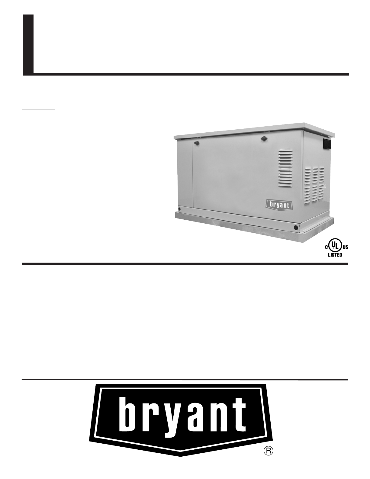
Home Standby - 7kW - 12kW - 15kW
INNOVATIVE DESIGN & PROTOTYPE TESTING are key components
of BRYANT’s success in “IMPROVING POWER BY DESIGN.” But it
doesn’t stop there. Total commitment to component testing, reliability
testing, environmental testing, destruction and life testing, plus testing
to applicable CSA, NEMA, EGSA, and other standards, allows you to
choose BRYANT with the confidence that these systems will provide
superior performance.
TEST CRITERIA:
>
PROTOTYPE TESTED
>
SYSTEM TORSIONAL TESTED
>
NEMA MG1-22 EVALUATION
>
MOTOR STARTING ABILITY
SOLID-STATE, FREQUENCY COMPENSATED VOLTAGE
REGULATION. This state-of-the-art power maximizing regulation
system is standard on all BRYANT models. It provides optimized
FAST RESPONSE to changing load conditions and MAXIMUM
MOTOR STARTING CAPABILITY by electronically torque-matching the
surge loads to the engine.
SINGLE SOURCE SERVICE RESPONSE from BRYANT’s dealer
network provides parts and service know-how for the entire unit, from
the engine to the smallest electronic component. You are never on
your own when you own a BRYANT system.
BRYANT TRANSFER SWITCHES. Long life and reliability are
synonymous with BRYANT systems. One reason for this confidence is
that the BRYANT product line includes its own transfer systems and
controls for total system compatibility.
FEATURES
Air-Cooled Gas Engine Generator Sets
Continuous Standby Power Rating Model ASPAS1BBA007 - 7kW 60Hz
Model ASPAS1BBA012 - 12kW 60Hz
Model ASPAS1BBA015 - 15kW 60Hz
INCLUDES:
• Automatic Transfer Switch
with Built-In Emergency Load Center
• Pre-wired External Connection Box
• Flexible Fuel Line
• Composite Mounting Pad
• Pre-wired conduits
• Natural Gas or LP Gas Operation
• GFCI duplex outlet & 12Vdc outlet
• UL Listed to Canadian safety standards
• 2 Year Limited Parts and Labor Warranty
Page 2

Page 3

Page 4

GENERATOR Model ASPAS1BBA007 (7kW) Model ASPAS1BBA012 (12kW) Model ASPAS1BBA015 (15kW)
Rated Maximum Continuous Power Capacity (LP)................................... 7,000 Watts* . . . . . . . . . . . . . . . . . . .12,000 Watts* . . . . . . . . . . . . . . . . . . .15,000 Watts*
Rated Maximum Continuous Power Capacity (NG)...................................6,000 Watts* . . . . . . . . . . . . . . . . . . . .12,000 Watts* . . . . . . . . . . . . . . . . . . .13,000 Watts*
Rated Voltage................................................................................................120/240 . . . . . . . . . . . . . . . . . . . . . . . .120/240 . . . . . . . . . . . . . . . . . . . . . . . .120/240
Rated Maximum Continuous Load Current
120 Volts ................................................................................................ 50.0 NG/58.3 LP . . . . . . . . . . . . . . . 100.0 NG/100.0 LP . . . . . . . . . . . . . . .108.3 NG/125.0 LP
240 Volts ................................................................................................ 25.0 NG/29.2 LP . . . . . . . . . . . . . . . .50.0 NG/ 50.0 LP . . . . . . . . . . . . . . . . .54.2 NG/62.5 LP
Main Line Circuit Breaker ............................................................................. 30 Amp . . . . . . . . . . . . . . . . . . . . . . . .50 Amp . . . . . . . . . . . . . . . . . . . . . . . .65 Amp
Phase ................................................................................................................ .1 . . . . . . . . . . . . . . . . . . . . . . . . . . . .1 . . . . . . . . . . . . . . . . . . . . . . . . . . . . . .1
Number of Rotor Poles .......................................................................................2 . . . . . . . . . . . . . . . . . . . . . . . . . . . . .2 . . . . . . . . . . . . . . . . . . . . . . . . . . . . . .2
Rated AC Frequency ........................................................................................60Hz . . . . . . . . . . . . . . . . . . . . . . . . . .60Hz . . . . . . . . . . . . . . . . . . . . . . . . . .60Hz
Power Factor .......................................................................................................1 . . . . . . . . . . . . . . . . . . . . . . . . . . . . .1 . . . . . . . . . . . . . . . . . . . . . . . . . . . . . .1
Battery Requirement (not included) ..........................................................Group 26 . . . . . . . . . . . . . . . . . . . . . . . .Group 26 . . . . . . . . . . . . . . . . . . . . . . .Group 26
12 Volts and . . . . . . . . . . . . . . . . . . . .12 Volts and . . . . . . . . . . . . . . . . . . . . .12 Volts and
350 Cold-cranking . . . . . . . . . . . . . . .525 Cold-cranking . . . . . . . . . . . . . . . .525 Cold-cranking
Amperes Minimum . . . . . . . . . . . . . . .Amperes Minimum . . . . . . . . . . . . . . . .Amperes Minimum
Shipping Weight (lbs.) (Includes Transfer Switch) .......................................375 . . . . . . . . . . . . . . . . . . . . . . . . . . . . . .470 . . . . . . . . . . . . . . . . . . . . . . . . . . . .487
Dimensions (L” x W” x H”)....................................................................... 48 x 24 x 28-1/4 . . . . . . . . . . . . . . . . .48 x 24 x 28-1/4 . . . . . . . . . . . . . . . . . .48 x 24 x 28-1/4
J
ENGINE Model ASPAS1BBA007 (7kW) Model ASPAS1BBA012 (12kW) Model ASPAS1BBA015 (15kW)
Type of Engine .................................................................................................OHVI . . . . . . . . . . . . . . . . . . . . . . .OHVI V-TWIN . . . . . . . . . . . . . . . . . . . .OHVI V-TWIN
Number of Cylinders ............................................................................................1 . . . . . . . . . . . . . . . . . . . . . . . . . . . . . .2 . . . . . . . . . . . . . . . . . . . . . . . . . . . . . .2
Rated Horsepower................................................................................. 14.5 @ 3,600 rpm . . . . . . . . . . . . . . . . .30 @ 3,600 rpm . . . . . . . . . . . . . . . . . .30 @ 3,600 rpm
Displacement................................................................................................... 410cc . . . . . . . . . . . . . . . . . . . . . . . . . .992cc . . . . . . . . . . . . . . . . . . . . . . . . . .992cc
Cylinder Block.........................................................................................Aluminum w/Cast . . . . . . . . . . . . . . . . .Aluminum w/Cast . . . . . . . . . . . . . . . . .Aluminum w/Cast
Iron Sleeve . . . . . . . . . . . . . . . . . . . . . .Iron Sleeve . . . . . . . . . . . . . . . . . . . . . .Iron Sleeve
Valve Arrangement...................................................................................Overhead Valve . . . . . . . . . . . . . . . . . .Overhead Valve . . . . . . . . . . . . . . . . . .Overhead Valve
Ignition System.................................................................................. .Solid-state w/Magneto . . . . . . . . . . . . .Solid-state w/Magneto . . . . . . . . . . . . .Solid-state w/Magneto
Compression Ratio.......................................................................................... .8.6:1 . . . . . . . . . . . . . . . . . . . . . . . . . . .9.5:1 . . . . . . . . . . . . . . . . . . . . . . . . . . .9.5:1
Starter............................................................................................................ .12 Vdc . . . . . . . . . . . . . . . . . . . . . . . . .12 Vdc . . . . . . . . . . . . . . . . . . . . . . . . . .12Vdc
Oil Capacity Including Filter..................................................................... Approx. 1.5 Qts . . . . . . . . . . . . . . . . . .Approx. 1.7 Qts. . . . . . . . . . . . . . . . . . .Approx. 1.7 Qts.
Operating RPM............................................................................................... .3,600 . . . . . . . . . . . . . . . . . . . . . . . . . .3,600 . . . . . . . . . . . . . . . . . . . . . . . . . .3,600
Fuel Consumption
Natural Gas cu.ft./hr.
1/2 Load . . . . . . . . . . . . . . . . . . . . . . . . . . . . . . . . . . . . . . . . . . . . . . . . . .66 . . . . . . . . . . . . . . . . . . . . . . . . . . . .152 . . . . . . . . . . . . . . . . . . . . . . . . . . . .156
Full Load . . . . . . . . . . . . . . . . . . . . . . . . . . . . . . . . . . . . . . . . . . . . . . . . .119 . . . . . . . . . . . . . . . . . . . . . . . . . . .215 . . . . . . . . . . . . . . . . . . . . . . . . . . . .220
Liquid Propane ft
3
/hr(gal/hr)
1/2 Load . . . . . . . . . . . . . . . . . . . . . . . . . . . . . . . . . . . . . . . . . . . . . . . .30(0.82) . . . . . . . . . . . . . . . . . . . . . . .56(1.53) . . . . . . . . . . . . . . . . . . . . . . . .58(1.58)
Full Load . . . . . . . . . . . . . . . . . . . . . . . . . . . . . . . . . . . . . . . . . . . . . . .54(1.47) . . . . . . . . . . . . . . . . . . . . . . .76(2.08) . . . . . . . . . . . . . . . . . . . . . . . .88(2.40)
Required fuel pressure to generator fuel inlet at all load ranges - 5 to 7 inches of water column for natural gas, 11 to 14 inches of water column for LP gas
CONTROLS
Model Switch
- AutoAutomatic Start on Utility failure/7 day exerciser
- Off. . . . . . . . . . . . . . . . . . . . . . . . . . . . . . . . . . . . . . . . . . . . . . . . . . . . . . . . . . . Stops unit. Power is removed control and charger still operate
- Manual/Test (start) . . . . . . . . . . . . . . . . . . . . . . . . . . . . . . . . . . . . . . . . . . . . . . Start with starter control, unit stays on. If utility fails, transfer to load takes place.
Engine Start Sequence. . . . . . . . . . . . . . . . . . . . . . . . . . . . . . . . . . . . . . . . . . . . Cyclic cranking: 7 sec. on, 7 rest (90 sec. maximum duration)
Engine Warm-up. . . . . . . . . . . . . . . . . . . . . . . . . . . . . . . . . . . . . . . . . . . . . . . . . 10 seconds
Engine Cool-Down . . . . . . . . . . . . . . . . . . . . . . . . . . . . . . . . . . . . . . . . . . . . . . . 1 minute
Starter Lock-out . . . . . . . . . . . . . . . . . . . . . . . . . . . . . . . . . . . . . . . . . . . . . . . . . Starter cannot re-engage until 5 sec. after engine has stopped.
2.5 Amp Timed Trickle Battery Charger. . . . . . . . . . . . . . . . . . . . . . . . . . . . . . . Standard
Automatic Voltage Regulator w/Overvoltage Protection . . . . . . . . . . . . . . . . . . . Standard
Automatic Low Oil Pressure Shutdown . . . . . . . . . . . . . . . . . . . . . . . . . . . . . . . Standard
Overspeed Shutdown . . . . . . . . . . . . . . . . . . . . . . . . . . . . . . . . . . . . . . . . . . . . . Standard, 72Hz
High Temperature Shutdown . . . . . . . . . . . . . . . . . . . . . . . . . . . . . . . . . . . . . . . Standard
Overcrank Protection . . . . . . . . . . . . . . . . . . . . . . . . . . . . . . . . . . . . . . . . . . . . . Standard
Safety Fuse. . . . . . . . . . . . . . . . . . . . . . . . . . . . . . . . . . . . . . . . . . . . . . . . . . . . . Standard
Rating definitions - Standby: Applicable for supplying emergency power for the duration of the utility power outage. No overload capability is available for this rating. (All ratings in accordance with
BS5514, ISO3046 and DIN6271). Prime (Unlimited Running Time): Unit not recommended for prime power applications. Applicable for supplying electric power in lieu of commercially purchased power.
Prime power is the maximum power available at variable load. A 10% overload capacity is available for 1 hour in 12 hours. (All ratings in accordance with BS5514, ISO3046, ISO8528 and DIN6271).
* Maximum wattage and current are subject to and limited by such factors as fuel Btu content, ambient temperature, altitude, engine power and condition, etc. Maximum power decreases about 3.5
percent for each 1,000 feet above sea level; and also will decrease about 1 percent for each 12° C (10° F) above 15.5° C (60°F).
Home Standby - 7kW - 12kW - 15kW
 Loading...