

Bryant 912SB, 925SA, 926TA A SERIES, 925TA, 925TA SERIES B Installation, Start-up, Operating And Service And Maintenance Instructions
912SB
SINGLE STAGE 4--WAY MULTIPOISE
CONDENSING GAS FURNACE
SERIES B
Installation, Start--up, Operating and
Service and Maintenance Instructions
NOTE: Read the entire instruction manual before starting the
installation.
SAFETY CONSIDERATIONS 3.........................
INTRODUCTION 4...................................
CODES AND STANDARDS 4...........................
ELECTROSTATIC DISCHARGE (ESD) PRECAUTIONS 4...
ACCESSORIES 5.....................................
LOCATION 8........................................
General 8.........................................
AIR FOR COMBUSTION AND VENTILATION 9..........
Introduction 9.....................................
CONDENSATE TRAP 13...............................
Upflow 13........................................
Downflow 13.....................................
Horizontal 13.....................................
CONDENSATE DRAIN 17.............................
INSTALLATION 20...................................
Upflow 20........................................
Downflow 20.....................................
Horizontal 21......................................
Filter Arrangement 21...............................
AIR DUCTS 29.......................................
General Requirements 29.............................
Ductwork Acoustical Treatment 29.....................
GAS PIPING 31......................................
ELECTRICAL CONNECTIONS 32.......................
115--V Wiring 32...................................
J--Box Installation 33................................
24--V Wiring 33....................................
Accessories 33.....................................
Alternate Power Supplies 33..........................
VENTING 37........................................
Special Venting Requirements for Installations in Canada 37.
General 38........................................
Materials 38.......................................
Venting Systems 38.................................
Locating the Vent Termination 39......................
Combustion Air and Vent Piping Insulation Guidelines 41...
START--UP, ADJUSTMENT, AND SAFETY CHECK 60......
General 60.........................................
Prime Condensate Trap 60.............................
Purge Gas Lines 60...................................
Adjustments 60......................................
SERVICE AND MAINTENANCE PROCEDURES 68........
Cleaning Heat Exchangers 73...........................
SEQUENCE OF OPERATION 76........................
PARTS REPLACEMENT GUIDE 80......................
TABLES
Loose Parts Bag 5.....................................
Minimum Clearances to Combustible Materials 5.............
Minimum Free Area Required 11.........................
Minimum Space Volumes 11.............................
Filter Size Information 23...............................
Opening Dimensions 25................................
Air Delivery CFM 30...................................
Maximum Capacity of Pipe 32...........................
Electrical Data 34......................................
Vent Termination Kit for Direct Vent (2--Pipe) System 39.......
Combustion--Air Vent Pipe, Fitting & Cement Material.. 45.....
Maximum Allowable Exposed Vent Lengths Insulation 46......
Maximum Equivalent Vent Length 47......................
Deductions from Maximum Equivalent Vent Length 47........
Blower Off Delay Setup Switch 62........................
Altitude Derate Multiplier for U.S.A. 63....................
Gas Rate 65..........................................
Orifice Size and Manifold Pressure 67.....................
CERTIFIED
Use of the AHRI Certified
manufacturer’s participation in the program. For
verification of certification for individual products,
go to www.ahridirectory.org.
Portions of the text and tables are reprinted from NFPA 54/ANSI
Z223.1--2012E, with permission of National Fire Protection
Association, Quincy, MA 02269 and American Gas Association,
Washington DC 20001. This reprinted material is not the complete
and official position of the NFPA or ANSI on the referenced
subject, which is represented only by the standard in its entirety.
TM
Mark indicates a
1

912SB
Required Notice for Massachusetts Installations
IMPORTANT
The Commonwealth of Massachusetts requires compliance with regulation 248 CMR as follows:
5.08: Modifications to NFPA--54, Chapter 10
2) Revise 10.8.3 by adding the following additional requirements:
a. For all side wall horizontally vented gas fueled equipment installed in every dwelling, building or structure used in
whole or in part for residential purposes, including those owned or operated by the Commonwealth and where the
side wall exhaust vent termination is less than seven (7) feet above finished grade in the area of the venting,
including but not limited to decks and porches, the following requirements shall be satisfied:
1. INSTALLATION OF CARBON MONOXIDE DETECTORS. At the time of installation of the side wall horizontal vented
gas fueled equipment, the installing plumber or gasfitter shall observe that a hard wired carbon monoxide detector with an
alarm and battery back--up is installed on the floor level where the gas equipment is to be installed. In addition, the installing
plumber or gasfitter shall observe that a battery operated or hard wired carbon monoxide detector with an alarm is installed on
each additional level of the dwelling, building or structure served by the side wall horizontal vented gas fueled equipment. It
shall be the responsibility of the property owner to secure the services of qualified licensed professionals for the installation of
hard wired carbon monoxide detectors
a. In the event that the side wall horizontally vented gas fueled equipment is installed in a crawl space or an attic, the hard wired
carbon monoxide detector with alarm and battery back--up may be installed on the next adjacent floor level.
b. In the event that the requirements of this subdivision can not be met at the time of completion of installation, the owner shall
have a period of thirty (30) days to comply with the above requirements; provided, however, that during said thirty (30)day
period, a battery operated carbon monoxide detector with an alarm shall be installed.
2. APPROVED CARBON MONOXIDE DETECTORS. Each carbon monoxide detector as required in accordance with the
above provisions shall comply with NFPA 720 and be ANSI/UL 2034 listed and IAS certified.
3. SIGNAGE. A metal or plastic identification plate shall be permanently mounted to the exterior of the building at a minimum
height of eight (8) feet above grade directly in line with the exhaust vent terminal for the horizontally vented gas fueled
heating appliance or equipment. The sign shall read, in print size no less than one--half (1/2) inch in size, ”GAS VENT
DIRECTLY BELOW. KEEP CLEAR OF ALL OBSTRUCTIONS”.
4. INSPECTION. The state or local gas inspector of the side wall horizontally vented gas fueled equipment shall not approve the
installation unless, upon inspection, the inspector observes carbon monoxide detectors and signage installed in accordance
with the provisions of 248 CMR 5.08(2)(a)1 through 4.
5. EXEMPTIONS: The following equipment is exempt from 248 CMR 5.08(2)(a)1 through 4:
(1.) The equipment listed in Chapter 10 entitled ”Equipment Not Required To Be Vented” in the most current edition of
NFPA 54 as adopted by the Board; and
(2.) Product Approved side wall horizontally vented gas fueled equipment installed in a room or structure separate from
the dwelling, building or structure used in whole or in part for residential purposes.
c. MANUFACTURER REQUIREMENTS -- GAS EQUIPMENT VENTING SYSTEM PROVIDED. When the
manufacturer of Product Approved side wall horizontally vented gas equipment provides a venting system design
or venting system components with the equipment, the instructions provided by the manufacturer for installation of
the equipment and the venting system shall include:
1. Detailed instructions for the installation of the venting system design or the venting system components; and
2. A complete parts list for the venting system design or venting system.
d. MANUFACTURER REQUIREMENTS -- GAS EQUIPMENT VENTING SYSTEM NOT PROVIDED. When
the manufacturer of a Product Approved side wall horizontally vented gas fueled equipment does not provide the
parts for venting the flue gases, but identifies “special venting systems”, the following requirements shall be
satisfied by the manufacturer:
1. The referenced “special venting system” instructions shall be included with the appliance or equipment installation
instructions; and
2. The “special venting systems” shall be Product Approved by the Board, and the instructions for that system shall include a
parts list and detailed installation instructions.
e. A copy of all installation instructions for all Product Approved side wall horizontally vented gas fueled equipment,
all venting instructions, all parts lists for venting instructions, and/or all venting design instructions shall remain
with the appliance or equipment at the completion of the installation.
For questions regarding these requirements, please contact the Commonwealth of Massachusetts Board of State Examiners of Plumbers and
Gas Fitters, 239 Causeway Street, Boston, MA 02114. 617--727--9952.
2
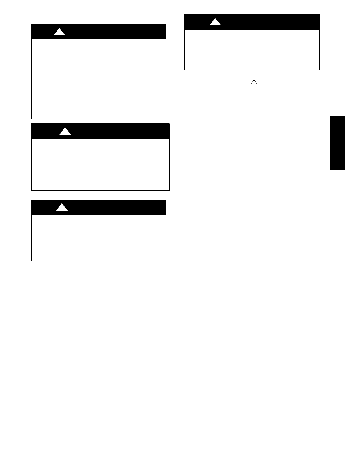
SAFETY CONSIDERATIONS
!
WARNING
FIRE, EXPLOSION, ELECTRICAL SHOCK, AND
CARBON MONOXIDE POISONING HAZARD
Failure to follow this warning could result in dangerous
operation, personal injury, death, or property damage.
Improper installation, adjustment, alteration, service,
maintenance, or use can cause carbon monoxide poisoning,
explosion, fire, electrical shock, or other conditions which
may cause personal injury or property damage. Consult a
qualified service agency, local gas supplier, or your
distributor or branch for information or assistance. The
qualified service agency must use only factory--authorized
and listed kits or accessories when modifying this product.
!
WARNING
FIRE HAZARD
Failure to follow this warning could result in personal injury,
death, or property damage.
Solvents, cements and primers are combustible. Keep away
from heat, sparks and open flame. Use only in well--ventilated
areas. Avoid breathing in vapor or allowing contact with skin
or eyes.
!
CAUTION
FURNACE RELIABILITY HAZARD
Failure to follow this caution may result in unit component
damage.
Application of this furnace should be indoors with special
attention given to vent sizing and material, gas input rate,
air temperature rise, unit leveling, and unit sizing.
Improper installation, adjustment, alteration, service, maintenance,
or use can cause explosion, fire, electrical shock, or other
conditions which may cause death, personal injury, or property
damage. Consult a qualified installer, service agency, or your
distributor or branch for information or assistance. The qualified
installer or agency must use factory-authorized kits or accessories
when modifying this product. Refer to the individual instructions
packaged with the kits or accessories when installing.
Installing and servicing heating equipment can be hazardous due to
gas and electrical components. Only trained and qualified
personnel should install, repair, or service heating equipment.
Untrained personnel can perform basic maintenance functions such
as cleaning and replacing air filters. All other operations must be
performed by trained service personnel. When working on heating
equipment, observe precautions in literature, on tags, and on labels
attached to or shipped with furnace and other safety precautions
that may apply.
These instructions cover minimum requirements and conform to
existing national standards and safety codes. In some instances,
these instructions exceed certain local codes and ordinances,
especially those that may not have kept up with changing
residential construction practices. We require these instructions as a
minimum for a safe installation.
Follow all safety codes. Wear safety glasses, protective clothing,
and work gloves. Have a fire extinguisher available. Read these
instructions thoroughly and follow all warnings or cautions
included in literature and attached to the unit.
!
CAUTION
CUT HAZARD
Failure to follow this caution may result in personal injury.
Sheet metal parts may have sharp edges or burrs. Use care
and wear appropriate protective clothing, safety glasses and
gloves when handling parts, and servicing furnaces.
This is the safety--alert symbol . When you see this symbol on
the furnace and in instructions or manuals, be alert to the potential
for personal injury.
Understand the signal words DANGER, WARNING,and
CAUTION. These words are used with the safety--alert symbol.
DANGER identifies the most serious hazards which will result in
severe personal injury or death. WARNING signifies a hazard
which could result in personal injury or death. CAUTION is used
to identify hazards which may result in minor personal injury or
product and property damage. NOTE and NOTICE are used to
highlight suggestions which will result in enhanced installation,
reliability, or operation.
1. Use only with type of gas approved for this furnace. Refer
to the furnace rating plate.
2. Install this furnace only in a location and position as specified in the “Location” section of these instructions.
3. Provide adequate combustion and ventilation air to the furnace space as specified in “Air for Combustion and Ventilation” section.
4. Combustion products must be discharged outdoors. Connect this furnace to an approved vent system only, as specified in the “Venting” section of these instructions.
5. Never test for gas leaks with an open flame. Use a commercially available soap solution made specifically for the detection of leaks to check all connections, as specified in the
“Gas Piping” section.
6. Always install furnace to operate within the furnace’s intended temperature--rise range with a duct system which hasan
external static pressure within the allowable range, as specified in the “Start--Up, Adjustments, and Safety Check”
section. See furnace rating plate.
7. When a furnace is installed so that supply ducts carry air
circulated by the furnace to areas outside the space containing the furnace, the return air shall also be handled by
duct(s) sealed to the furnace casing and terminating outside
the space containing the furnace. See “Air Ducts” section.
8. A gas--fired furnace for installation in a residential garage
must be installed as specified in the warning box in the
“Location” section.
9. The furnace may be used for construction heat provided that
the furnace installation and operation complies with the first
CAUTION in the LOCATION section of these instructions.
10. These Multipoise Gas--Fired Furnaces are CSA design--certified for use with natural and propane gases (see furnace
rating plate) and for installation in alcoves, attics, basements, closets, utility rooms, crawlspaces, and garages. The
furnace is factory--shipped for use with natural gas. A CSA
(A.G.A. and C.G.A.) listed accessory gas conversion kit is
required to convert furnace for use with propane gas.
11. See Table 2 for required clearances to combustible construction.
12. Maintain a 1--in. (25 mm) clearance from combustible materials to supply air ductwork for a distance of 36 in. (914
mm) horizontally from the furnace. See NFPA 90B or local
code for further requirements.
912SB
3

13. These furnaces SHALL NOT be installed directly on carpeting, combustible tile, or any other combustible material other than wood flooring. In downflow installations, factory
accessory floor base MUST be used when installed on combustible materials and wood flooring. Special base is not required when this furnace is installed on manufacturer’s Coil
Assembly Part No. CNRV, CNPV, CAP, or CAR or when
Coil Box Part No. KCAKC is used. See Table 2 for clearance to combustible construction information.
INTRODUCTION
This 4--way multipoise Category IV condensing furnace is CSA
design--certified as a direct--vent (2-pipe) or non-direct vent
(1-pipe) furnace. See Fig. 2. The furnace is factory--shipped for
use with natural gas. The furnace can be converted in the field for
use with propane gas when a factory-supplied conversion kit is
used. Refer to the furnace rating plate for conversion kit
information.
These furnaces are not approved for installation in recreational
vehicles or outdoors. Single--stage furnaces (40,000 through
120,000) are approved for installation in manufactured
housing/mobile homes with manufacturer--approved accessory.
The conversion kit is required for use with both natural and
912SB
propane gas. The furnace must also be installed on a
factory-supplied accessory combustible floor base or evaporator
coil casing.
This furnace is designed for minimum continuous return--air
temperature of 60_F(15_C) db or intermittent operation down to
55_F(13_C) db such as when used with a night setback
thermostat. Return-air temperature must not exceed 80_F(27_C)
db. Failure to follow these return-air temperature limits may affect
reliability of heat exchangers, motors, and controls. See Fig. 3.
The furnace should be sized to provide 100 percent of the design
heating load requirement plus any margin that occurs because of
furnace model size capacity increments. Heating load estimates can
be made using approved methods available from Air Conditioning
Contractors of America (Manual J); American Society of Heating,
Refrigerating, and Air--Conditioning Engineers; or other approved
engineering methods. Excessive oversizing of the furnace could
cause the furnace and/or vent to fail prematurely.
For accessory installation details, refer to the applicable instruction
literature.
NOTE: Remove all shipping materials, loose parts bag, and
literature before operating the furnace. See Table 1.
CODES AND STANDARDS
Follow all national and local codes and standards in addition
to these instructions. The installation must comply with
regulations of the serving gas supplier, local building, heating,
plumbing, and other codes. In absence of local codes, the
installation must comply with the national codes listed below and
all authorities having jurisdiction.
In the United States and Canada, follow all codes and standards for
the following:
Safety
S US: National Fuel Gas Code (NFGC) NFPA 54--2012/ANSI
Z223.1--2012 and the Installation Standards, Warm Air Heating
and Air Conditioning Systems ANSI/NFPA 90B
S A manufactured (Mobile) home installation must conform with
the Manufactured Home Construction and Safety Standard, Title
24 CFR, Part 3280, or when this standard is not applicable, the
Standard for Manufactured Home Installation (Manufactured
Home Sites, Communities, and Set-Ups),ANSI/NCS A225.1,
and/or CAN/CSA-Z240, MH Series Mobile Homes
S CANADA: National Standard of Canada, Natural Gas and
Propane Installation Code (NSCNGPIC) CAN/CSA
B149.1--2010
General Installation
S US: NFGC and the NFPA 90B. For copies, contact the National
Fire Protection Association Inc., Batterymarch Park, Quincy,
MA 02269; or for only the NFGC contact the American Gas
Association, 400 N. Capitol, N.W., Washington DC 20001
S CANADA: NSCNGPIC. For a copy, contact Standard Sales,
CSA International, 178 Rexdale Boulevard, Etobicoke
(Toronto), Ontario, M9W 1R3, Canada
Combustion and Ventilation Air
S US: Section 9.3 of the NFPA54/ANSI Z223.1--2012 Air for
Combustion and Ventilation
S CANADA: Part 8 of the CAN/CSA B149.1--2010, Venting
Systems and Air Supply for Appliances
Duct Systems
S US and CANADA: Air Conditioning Contractors Association
(ACCA) Manual D, Sheet Metal and Air Conditioning Contractors
National Association (SMACNA), or American Society of Heating,
Refrigeration, and Air Conditioning Engineers (ASHRAE) 2005
Fundamentals Handbook Chapter 35
Acoustical Lining and Fibrous Glass Duct
S US and CANADA: current edition of SMACNA, NFPA 90B as
tested by UL Standard 181 for Class I Rigid Air Ducts
Gas Piping and Gas Pipe Pressure Testing
S US: NFPA 54/ANSI Z223.1--2012 NFGC; Chapters 5, 6, 7, and 8
and national plumbing codes.
CANADA: CAN/CSA--B149.1--2010, Parts 4, 5, 6, and 9.
In the state of Massachusetts:
S This product must be installed by a licensed plumber or gas fitter.
S When flexible connectors are used, the maximum length shall
not exceed 36 in. (914 mm).
S When lever type gas shutoffs are used they shall be T--handle type.
S The use of copper tubing for gas piping is not approved by the
state of Massachusetts.
Electrical Connections
S US: National Electrical Code (NEC) ANSI/NFPA 70--2011
S CANADA: Canadian Electrical Code CSA C22.1
ELECTROSTATIC DISCHARGE (ESD)
PRECAUTIONS PROCEDURE
!
CAUTION
FURNACE RELIABILITY HAZARD
Failure to follow this caution may result in unit component
damage.
Electrostatic discharge can affect electronic components.
Take precautions during furnace installation and servicing
to protect the furnace electronic control. Precautions will
prevent electrostatic discharges from personnel and hand
tools which are held during the procedure. These
precautions will help to avoid exposing the control to
electrostatic discharge by putting the furnace, the control,
and the person at the same electrostatic potential.
4
1. Disconnect all power to the furnace. Multiple disconnects
may be required. DO NOT TOUCH THE CONTROL
OR ANY WIRE CONNECTED TO THE CONTROL
PRIOR TO DISCHARGING YOUR BODY’S
ELECTROSTATIC CHARGE TO GROUND.
2. Firmly touch the clean, unpainted, metal surface of the furnace chassis which is close to the control. Tools held in a
person’s hand during grounding will be satisfactorily discharged.
3. After touching the chassis, you may proceed to service the
control or connecting wires as long as you do nothing to
recharge your body with static electricity (for example; DO
NOT move or shuffle your feet, do not touch ungrounded
objects, etc.).
4. If you touch ungrounded objects (and recharge your body
with static electricity), firmly touch a clean, unpainted metal
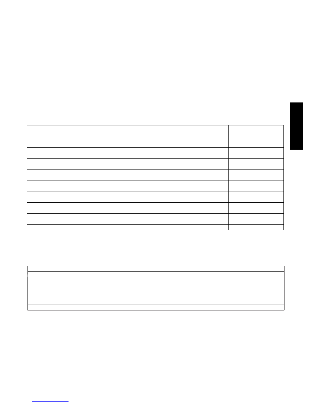
Table 1 – Factory--Supplied Installation Parts
DESCRIPTION QUANTITY
Outlet Choke Plate (provided with 40K BTUH furnaces only; see Note) 1
AirIntakePipeFlange 1
Vent Pipe Flange 1
Pipe Flange Gaskets 2
Sharp Tip Screws (Vent and Inlet Flanges) 10
Vent Pipe Coupling 1
Vent Pipe Coupling Clamps 2
Pressure Switch Tube 1
Rubber Drain Elbow 1
Drain Tube Clamps 4
1 / 2 --- i n . C P V C to 3 / 4 --- i n . P V C P i p e A d a p t e r 1
Gas Line Grommet 1
Junction Box Cover 1
Junction Box Base 1
Green Ground Screw 1
Blunt Tip Screws (Junction Box) 3
Thermostat Wire Grommet 1
Drain Extension Tube (Z ---pipe) (Provided separately in furnace) 1
surface of the furnace again before touching control or
wires.
5. Use this procedure for installed and uninstalled (ungrounded) furnaces.
6. Before removing a new control from its container, discharge
your body’s electrostatic charge to ground to protect the
control from damage. If the control is to be installed in a
furnace, follow items 1 through 4 before bringing the control or yourself in contact with the furnace. Put all used and
new controls into containers before touching ungrounded
objects.
7. An ESD service kit (available from commercial sources)
mayalsobeusedtopreventESDdamage.
ACCESSORIES
See Product Data Sheet for a list of accessories for this product.
912SB
NOTE: Only used for 40K BTUH furnaces from 0--2000 ft. (0 to 610 M) above sea level for total equivalent vent lengths under 10 ft. (3 M)
Table 2 – Minimum Clearances to Combustible Materials for All Units
POSITION CLEARANCE
REAR 0
FRONT (Combustion air openings in furnace and in structure) 1in.(25mm)
Required for service *24 in. (610 mm)
All Sides of Supply Plenum *1 in. (25 mm)
Sides 0
Vent 0
Top of Furnace 1in.(25mm)
*Consult local building codes.
5
912SB
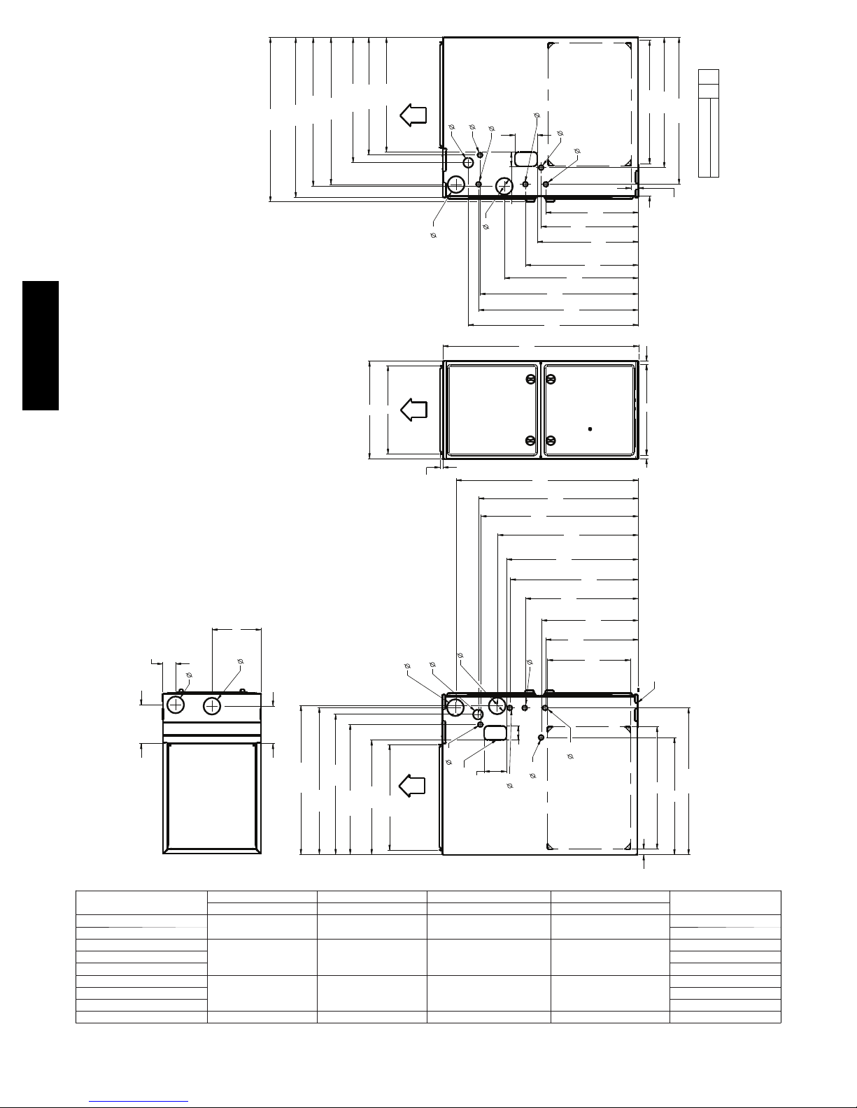
29 1/2
[749.3]
28 3/4
[730.5]
[678.1]
26 11/16
26 3/8
[669.9]
[557.4]
21 15/16
21 1/16
[535.8]
20 5/8
[522.7]
AIR FLOW
3
[76.2]
1 3/4
[44.5]
AIR INTAKE
7/8
GAS CONN
[22.2]
E
REV
1
SHT
23 3/8
7/8
[22.2] POWER CONN
[63.5]
SIDE INLET
7/8
[101.6]
[889.0]
28 3/8
[720.4]
[757]
29 13/16
[22.2]
28 5/8
17 7/16
24
[726.9]
7/8
[442.3]
[609.7]
[22.2]
THERMOSTAT ENTRY
[420.9]
16 9/16
[458.6]
18 1/16
20 1/4
[513.9]
4
35
7/8
[22.2]
2 1/2
3
[76.2 ]
21 5/8
[549.5]
BOTTOM INLET
6 1/16
[154.0]
11/16
[17.5]
[592.0]
1 5/16
[668.8]
26 5/16
[33.3]
SD5024-4
PART NUMBER
NEXT SHEET
2
B
A
NOTES:
1. Doors may vary by model.
2. Minimum return-air openings at furnace, based on metal duct. If ex duct is used,
see ex duct manufacturer's recommendations for equivalent diameters.
a. For 800 CFM-16-in. (406 mm) round or 14 1/2 x 12-in. (368 x 305 mm) rectangle.
b. For 1200 CFM-20-in. (508 mm) round or 14 1/2 x 19 1/2-in. (368 x 495 mm) rectangle.
c. For 1600 CFM-22-in. (559 mm) round or 14 1/2 x 22 1/16-in. (368 x 560mm) rectangle.
d. Return air above 1800 CFM at 0.5 in. w.c. ESP on 24.5" casing, requires one of the following
congurations: 2 sides, 1 side and a bottom or bottom only. See Air Delivery table in this
document for specic use to allow for sucient airow to the furnace.
3. Vent and Combustion air pipes through blower compartment must
use accessory “Vent Kit - Through the Cabinet”. See accessory list for
current part number.
D
[58.4]
6 15/16
[176.1]
2 3/10
3
[76.2]
VENT
3
[76.2]
AIR INTAKE
[170.1]
6 11/16
TOP VIEW
[678.1]
26 11/16
26 3/8
[670.0]
25 1/8
[638.7]
23 5/16
[592.9]
20 5/8
[522.7]
19 1/8
OUTLET WIDTH
3
[76.2]
AIR INTAKE
[485.8]
AIR FLOW
5/8
[15.8]
1 3/4
AIR FLOW
[44.5]
GAS CONN
3
[76.2]
VENT
7/8
[22.2]
4
[101.6]
CONDENSATE DRAIN TRAP
LOCATION
2 1/2
7/8
[22.2]
32 5/8
[829.5]
28 5/8
[715.9]
28 3/16
7/8
[22.2] POWER CONN
[63.5]
7/8
[22.2]
[726.4]
25 3/16
[595.6]
23 7/16
20 1/4
[513.9]
16 9/16
7/8
SIDE INLET
[639.1]
[581.9]
22 15/16
[439.2]
17 5/16
[420.9]
[376.3]
14 13/16
[22.2]
THERMOSTAT ENTRY
C
WIDTH
BOTTOM RETURN
NOTE: ALL DIMENSIONS IN INCH [MM]
11/16
[17.5]
SEE NOTE #3
[668.8]
22
26 5/16
21
[534.0]
[558.3] (BOTH SIDES)
[25.4]
1 (BOTH SIDES)
912SB
FURNACE SIZE
30040
36060 125.0 (56.8)
A B C D
CABINET WIDTH OUTLET WIDTH BOTTOM INLET WIDTH AIR INTAKE
14--- 3/16 (361) 12--- 1/2 (319) 12--- 9/16 (322) 7--- 1/8 (181)
36040
48060 142.0 (64.5)
17--- 1/2 (445) 15--- 7/8 (403) 16 (406) 8--- 3/4 (222)
48080 151.0 (68.6)
60080
48100 166.5 (75.7)
21 (533) 19--- 3/8 (492) 19--- 1/2 (495) 10--- 1/2 (267)
66100 166.5 (75.7)
66120 24---1/2 (622) 22 --- 7/ 8 (581) 23 (584) 12--- 1/4 (311) 184.0 (83.6)
Fig. 1 -- Dimensional Drawing
6
SHIP WT.
LB (KG)
121.0 (55.0)
132.0 (60.0)
158.5 (72.0)
A12267
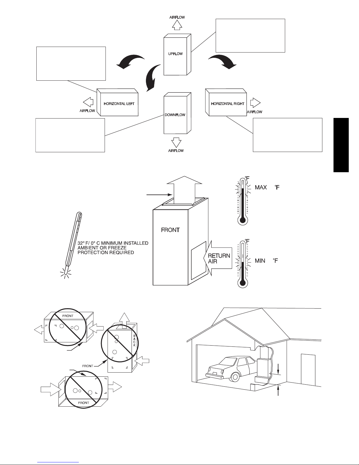
THE BLOWER IS LOCATED
TO THE RIGHT OF THE
BURNER SECTION, AND
CONDITIONED AIR IS
DISCHARGED TO THE LEFT.
THE BLOWER IS
LOCATED BELOW THE
BURNER SECTION, AND
CONDITIONED AIR IS
DISCHARGED UPWARD.
THE BLOWER IS
LOCATED ABOVE THE
BURNER SECTION, AND
CONDITIONED AIR IS
DISCHARGED DOWNWARD
Fig. 2 -- Multipoise Orientations
SUPPLY AIR
Fig. 3 -- Freeze Protection and Return Air Temperature
THE BLOWER IS
LOCATED TO THE LEFT
OF THE BURNER SECTION,
AND CONDITIONED AIR IS
DISCHARGED TO THE RIGHT.
A12181
80 / 27˚C
60
/ 16˚C
A10490
912SB
BACK POSITIONED
DOWNWARD
BACK POSITIONED
UPWARD
Fig. 4 -- Prohibited Installations
AIR RETURN
CUT IN BACK
A12182
18-IN. (457.2 mm)
MINIMUM TO BURNERS
A93044
Fig. 5 -- Installation in a Garage
7
LOCATION
!
CAUTION
PERSONAL INJURY AND/OR PROPERTY
DAMAGE HAZARD
Improper use or installation of this furnace may result in
premature furnace component failure. This gas furnace may
be used for heating buildings under construction provided
that:
--The furnace is permanently installed with all electrical
wiring, piping, venting and ducting installed according to
these installation instructions. A return air duct is provided,
sealed to the furnace casing, and terminated outside the
space containing the furnace. This prevents a negative
pressure condition as created by the circulating air blower,
causing a flame rollout and/or drawing combustion
products into the structure.
--The furnace is controlled by a thermostat. It may not be
“hot wired” to provide heat continuously to the structure
without thermostatic control.
912SB
--Clean outside air is provided for combustion. This is to
minimize the corrosive effects of adhesives, sealers and
other construction materials. It also prevents the
entrainment of drywall dust into combustion air, which can
cause fouling and plugging of furnace components.
--The temperature of the return air to the furnace is
maintained between 55_F(13_C) and 80_F(27_C), with
no evening setback or shutdown. The use of the furnace
while the structure is under construction is deemed to be
intermittent operation per our installation instructions.
--The air temperature rise is within the rated rise range on
the furnace rating plate, and the gas input rate has been set
to the nameplate value.
--The filters used to clean the circulating air during the
construction process must be either changed or thoroughly
cleaned prior to occupancy.
--The furnace, ductwork and filters are cleaned as necessary
to remove drywall dust and construction debris from all
HVAC system components after construction is completed.
--Verify proper furnace operating conditions including
ignition, gas input rate, air temperature rise, and venting
according to these installation instructions.
General
These furnaces are shipped with materials to assist in proper
furnace installation. These materials are shipped in the main
blower compartment.
See Table 1 for loose parts bag contents.
This furnace must:
S be installed so the electrical components are protected from
water.
S not be installed directly on any combustible material other than
wood flooring (refer to SAFETY CONSIDERATIONS).
S be located close to the chimney or vent and attached to an air
distribution system. Refer to Air Ducts section.
S be provided ample space for servicing and cleaning. Always
comply with minimum fire protection clearances shown in Table
2 or on the furnace clearance to combustible construction label.
!
WARNING
CARBON MONOXIDE POISONING / COMPONENT
DAMAGE HAZARD
Failure to follow this warning could result in personal injury
or death and unit component damage.
Corrosive or contaminated air may cause failure of parts
containing flue gas, which could leak into the living space.
Air for combustion must not be contaminated by halogen
compounds, which include fluoride, chloride, bromide, and
iodide. These elements can corrode heat exchangers and
shorten furnace life. Air contaminants are found in aerosol
sprays, detergents, bleaches, cleaning solvents, salts, air
fresheners, and other household products. Do not install
furnace in a corrosive or contaminated atmosphere. Make
sure all combustion and circulating air requirements are met,
in addition to all local codes and ordinances.
The following types of furnace installations may require
OUTDOOR AIR for combustion due to chemical exposures:
S Commercial buildings
S Buildings with indoor pools
S Laundry rooms
S Hobby or craft rooms
S Chemical storage areas
If air is exposed to the following substances, it should not be used
for combustion air, and outdoor air may be required for
combustion:
S Permanent wave solutions
S Chlorinated waxes and cleaners
S Chlorine based swimming pool chemicals
S Water softening chemicals
S De--icing salts or chemicals
S Carbon tetrachloride
S Halogen type refrigerants
S Cleaning solvents (such as perchloroethylene)
S Printing inks, paint removers, varnishes, etc.
S Hydrochloric acid
S Cements and glues
S Antistatic fabric softeners for clothes dryers
S Masonry acid washing materials
All fuel--burning equipment must be supplied with air for fuel
combustion. Sufficient air must be provided to avoid negative
pressure in the equipment room or space. A positive seal must be
made between the furnace cabinet and the return--air duct to
prevent pulling air from the burner area.
!
WARNING
FIRE, INJURY OR DEATH HAZARD
Failure to follow this warning could result in personal
injury, death and/or property damage.
When the furnace is installed in a residential garage, the
burners and ignition sources must be located at least 18 in.
(457 mm) above the floor. The furnace must be located or
protected to avoid damage by vehicles. When the furnace is
installed in a public garage, airplane hangar, or other
building having a hazardous atmosphere, the furnace must
be installed in accordance with the NFPA 54/ANSI
Z223.1--2012 or CAN/CSA B149.2--2010. See Fig. 5.
8
!
WARNING
!
CAUTION
FIRE HAZARD
Failure to follow this warning could result in personal
injury, death and/or property damage.
Do not install the furnace on its back or hang furnace with
control compartment facing downward. Safety control
operation will be adversely affected. Never connect
return--air ducts to the back of the furnace. See Fig. 4.
Location Relative to Cooling Equipment
The cooling coil must be installed parallel with, or on the
downstream side of the unit to avoid condensation in the heat
exchangers. When installed parallel with the furnace, dampers or
other flow control must prevent chilled air from entering the
furnace. If the dampers are manually operated, they must be
equipped with means to prevent operation of either unit unless the
damper is in the full--heat or full--cool position.
AIR FOR COMBUSTION AND
VENTILATION
Introduction
Direct Vent (2--pipe) Applications
When the furnace is installed as a direct vent (2-pipe) furnace, no
special provisions for air for combustion are required. However,
other gas appliances installed in the space with the furnace may
require outside air for combustion. Follow the guidelines below to
insure that other gas appliances have sufficient air for combustion.
Non--Direct Vent (1--pipe) Applications
When the furnace is installed as a non-direct vent (1-pipe) furnace,
it will be necessary to insure there is adequate air for combustion.
Other gas appliances installed with the furnace may also require air
for combustion and ventilation in addition to the amount of
combustion air and ventilation air required for the furnace. Follow
the guidelines below to insure that the furnace and other gas
appliances have sufficient air for combustion.
Ventilated Combustion Air Applications
When the furnace is installed using the ventilated combustion air
option, the attic or crawlspace must freely communicate with the
outdoor to provide sufficient air for combustion. The combustion
air pipe cannot be terminated in attics or crawlspaces that use
ventilation fans designed to operate during the heating season. If
ventilation fans are present in these areas, the combustion air pipe
must terminate outdoors as a Direct Vent/ 2-Pipe system.
All air for combustion is piped directly to the furnace from a space
that is well ventilated with outdoor air (such as an attic, crawl space
or equipment closet) and the space is well isolated from the living
space or garage. In addition, other gas appliances installed in the
space with the furnace may require outside air for combustion.
Follow the guidelines below to insure that the roof or crawlspace
walls have sufficient free area to provide sufficient air for
combustion and ventilation for the furnaces. The guidelines below
can be used to insure that other gas appliances have sufficient air
for combustion.
Provisions for adequate combustion, ventilation, and dilution air
must be provided in accordance with:
S U.S.A. Installations: Section 9.3 of the NFPA 54/ANSI
Z223.1--2012 , Air for Combustion and Ventilation and
applicable provisionsof the local building codes.
S Canada: Part 8 of the CAN/CSA--B149.1--2010, Venting
Systems and Air Supply for Appliances.
FURNACE CORROSION HAZARD
Failure to follow this caution may result in furnace damage.
Air for combustion must not be contaminated by halogen
compounds, which include fluoride, chloride, bromide, and
iodide. These elements can corrode heat exchangers and
shorten furnace life. Air contaminants are found in aerosol
sprays, detergents, bleaches, cleaning solvents, salts, air
fresheners, and other household products.
!
WARNING
CARBON MONOXIDE POISONING HAZARD
Failure to follow this warning could result in personal
injury or death.
The operation of exhaust fans, kitchen ventilation fans,
clothes dryers, attic exhaust fans or fireplaces could create a
NEGATIVE PRESSURE CONDITION at the furnace.
Make--up air MUST be provided for the ventilation devices,
in addition to that required by the furnace. Refer to the
Carbon Monoxide Poisoning Hazard warning in the venting
section of these instructions to determine if an adequate
amount ofmake--up air is available.
The requirements for combustion and ventilation air depend upon
whether or not the furnace is located in a space having a volume of
at least 50 cubic feet per 1,000 Btuh input rating for all gas
appliances installed in the space.
S Spaces having less than 50 cubic feet per 1,000 Btuh (4.8 cubic
meters per kW) require the Outdoor Combustion Air Method.
S Spaces having at least 50 cubic feet per 1,000 Btuh (4.8 cubic
meters per kW) may use the Indoor Combustion Air,
Standard or Known Air Infiltration Method.
Outdoor Combustion Air Method
1. Provide the space with sufficient air for proper combustion,
ventilation, and dilution of flue gases using permanent horizontal or vertical duct(s) or opening(s) directly communicating with the outdoors or spaces that freely communicate
with the outdoors.
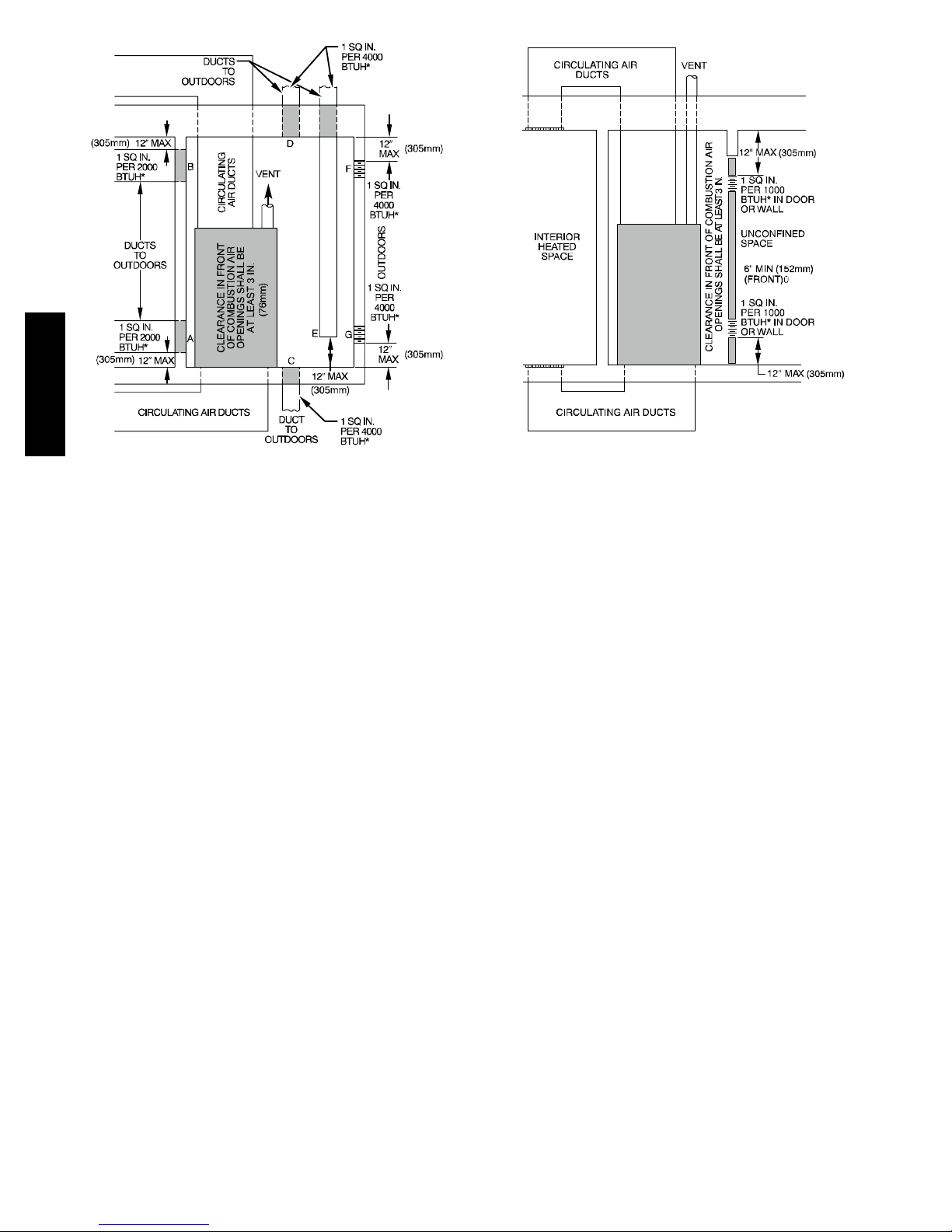
2. Fig. 6 illustrates how to provide TWO OUTDOOR
OPENINGS, one inlet and one outlet combustion and ventilation air opening, to the outdoors.
a. One opening MUST commence within 12 in. (300 mm)
of the ceiling and the second opening MUST commence
within 12 in. (300 mm) of the floor.
b. Size openings and ducts per Fig. 6 and Table 3.
c. TWO HORIZONTAL DUCTSrequire 1 sq. in. (645 sq.
mm) of free areaper 2,000 Btuh (1,100 mm
binedinput for allgasappliances in the space perFig.6 and
Tab le 3 .
d. TWO OPENINGS OR VERTICAL DUCTS require 1
sq. in. (645 sq. mm) of free area per 4,000 Btuh (550
2
/kW) for combined input of all gas appliances in the
mm
space per Fig. 6 and Table 3.
3. ONE OUTDOOR OPENING requires:
a. 1 sq. in. (645 sq. mm) of free area per 3,000 Btuh (734
2
mm
/kW) for combined input of all gas appliances in the
space per Fig. 6 and Table 3.
b. Not less than thesum of the areas ofall vent connectorsin
the space.
2
/kW) of com-
912SB
9
The opening shall commence within 12 in. (300 mm) of the
ceiling. Appliances in the space shall have clearances of at least 1
in. (25 mm) from the sides and back and 6 in. (150 mm) from the
front. The opening shall directly communicate with the outdoors or
shall communicate through a vertical or horizontal duct to the
outdoors or spaces (crawl or attic) that freely communicate with the
outdoors.
Indoor Combustion AirE NFPA & AGA
Standard and Known--Air--Infiltration Rate Methods
Indoor air is permitted for combustion, ventilation, and dilution, if
the Standard or Known--Air--Infiltration Method is used.
!
WARNING
CARBON MONOXIDE POISONING HAZARD
Failure to follow this warning could result in personal
injury or death.
Many homes require air to be supplied from outdoors
for furnace combustion, ventilation, and dilution of flue
gases.
912SB
The furnace combustion air supply must be provided in
accordance with this instruction manual.
Standard Method
1. The space has no less volume than 50 cubic feet per 1,000
Btuh of the maximum input ratings for all gas appliances
installed in the space and
2. The air infiltration rate is not known to be less than 0.40 air
changes per hour (ACH).
The Known Air Infiltration Rate Method shall be used, if the
infiltration rate is known to be:
1. Less than 0.40 ACH and
2. Equal to or greater than 0.10 ACH
Infiltration rates greater than 0.60 ACH shall not be used. The
minimum required volume of the space varies with the number of
ACH and shall be determined per Table 4 or Equations 1 and 2.
Determine the minimum required volume for each appliance in the
space and add the volumes together to get the total minimum
required volume for the space.
Table 4 -- Minimum Space Volumes were determined by using the
following equations from the current edition of the National Fuel
Gas Code ANSI Z223.1/NFPA 54, 9.3.2.2:
1. For other than fan--assisted appliances, such as a draft
hood--equipped water heater:
3
I
other
1000 Btu/hr
3
I
1000 Btu/hr
fan
Volume
2. For fan--assisted appliances such as this furnace:
Volume
Other
Fan
=
=
21ft
ACH
15ft
ACH
A04002
The following requirements apply to the Standard Method and to
the Known Air Infiltration Rate Method.
1. Adjoining rooms can be considered part of a space if:
a. There are no closeable doors between rooms.
b. Combining spaces on same floor level. Each opening shall
have freearea ofat least1 in.
of the total input rating of all gas appliances in the space,
but not less than 100 in.
commence within 12 in. (300 mm) of the ceiling and the
second opening shall commence within 12 in. (300 mm)
of thefloor.The minimumdimensionof air openingsshall
be at least 3 in. (80 mm). See Fig. 7.
c. Combining spaceon different floor levels. The volumes of
spaces on different floor levels shall be considered as communicating spaces if connected by oneor morepermanent
openings in doors or floors having free area of at least 2
2
/1,000 Btuh (4,400 mm2/kW) of total input rating of
in.
all gas appliances.
2. An attic or crawlspace may be considered a space that freely
communicates with the outdoors provided there are adequate permanent ventilation openings directly to outdoors
having free area of at least 1--in.
rating for all gas appliances in the space.
3. In spaces that use the Indoor Combustion Air Method, in-
filtration should be adequate to provide air for combustion,
permanent ventilation and dilution of flue gases. However,
in buildings with unusually tight construction, additional air
MUST be provided using the methods described in the
Outdoor Combustion Air Method section.
4. Unusually tight construction is defined as Construction
with:
a. Walls and ceilingsexposed to theoutdoorshave acontinu-
ous, sealed vapor barrier. Openings are gasketed or sealed
and
b. Doors and openable windows are weatherstripped and
c. Other openingsare caulkedor sealed.These includejoints
around window and door frames, between sole plates and
floors, between wall--ceiling joints, between wall panels,
at penetrations for plumbing, electrical and gas lines, etc.
2
/1,000Btuh (2,000 mm2/kW)
2
(0.06 m2). One opening shall
2
/4,000 Btuh of total input
Combination of Indoor and Outdoor Air
1. Indoor openings shall comply with the Indoor Combus-
tion Air Method below and,
2. Outdoor openings shall be located as required in the Out-
door Combustion Air Method mentioned previously and,
3. Outdoor openings shall be sized as follows:
a. Calculate the Ratio of all Indoor Spacevolume divided by
required volumefor Indoor Combustion Air Method be-
low.
b. Outdoor opening sizereduction Factor is 1 minus the Ra-
tio in a. above.
c. Minimum size of Outdoor openings shall be the size re-
quiredin Outdoor Combustion AirMethod above multi-
plied by reduction Factor in b. above. The minimum dimension ofairopeningsshallbenot lessthan 3in. (80mm).
If:Iother = combined input of all other than fan--assisted appliances
in Btuh/hr
Ifan = combined input of all fan--assisted appliances in Btuh/hr
ACH = air changes per hour (ACH shall not exceed 0.60.)
A04003
10
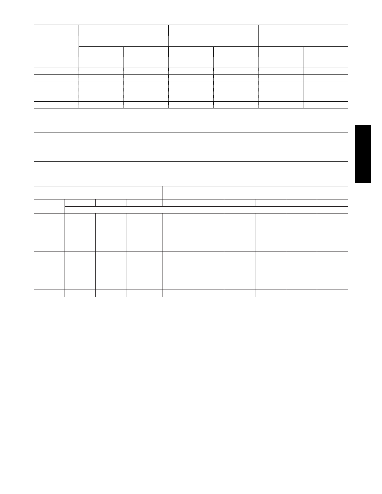
Table 3 – Minimum Free Area Required for Each Combustion Air Opening or Duct to Outdoors
TWO HORIZONTAL DUCTS
(1 SQ. IN./2,000 BTUH)
FURNACE
INPUT
(BTUH)
40,000* 20 (12904) 5 (127) 14 (8696) 5 (127) 10 (6452) 4 (102)
60,000 30 (19355) 6 (152) 20 (13043) 5 (127) 15 (9678) 5 (127)
80,000 40 (25807) 7 (178) 27 (17391) 6 (152) 20 (12904) 5 (127)
100,000 50 (32258) 8 (203) 34 (21739) 7 (178) 25 (16130) 6 (152)
120,000 60 (38709) 9 (229) 40 (26087) 7 (178) 30 (19355) 6 (152)
140,000* 70 (45161) 10 (254) 47 (30435) 8 (203) 35 (22581) 7 (178)
*Not all families have these models.
(1,100 SQ. MM/KW)
Free Area of
Opening and
Duct
Sq. In (Sq. mm)
Round Duct
In. (mm) Dia
SINGLE DUCT OR OPENING
(1 SQ. IN./3,000 BTUH)
(734 SQ. MM/KW)
Free Area of
Opening and
Duct
Sq. In (Sq. mm)
Round Duct
In. (mm) Dia
TWO OPENINGS OR
VERTICAL DUCTS
(1 SQ. IN./4,000 BTUH)
(550 SQ. MM/KW)
Free Area of
Opening and
Duct
Sq. In (mm)
Round Duct
In. (mm) Dia.
EXAMPLES: Determining Free Area
FURNACE WATER HEATER TOTAL INPUT
100,000 + 30,000 = (130,000 divided by 4,000) = 32.5 Sq. In. for each two Vertical Ducts or Openings
60,000 + 40,000 = (100,000 divided by 3,000) = 33.3 Sq. In. for each Single Duct or Opening
80,000 + 30,000 = (110,000 divided by 2,000) = 55.0 Sq. In. for each two Horizontal Ducts
Table 4 – Minimum Space Volumes for 100% Combustion, Ventilation and Dilution Air from Outdoors
OTHER THAN FAN-ASSISTED TOTAL
(1,000’S BTUH GAS INPUT RATE)
ACH
0.60
0.50
0.40
0.30
0.20
0.10
0.00 NP NP NP NP NP NP NP NP NP
NP = Not Permitted
30 40 50 40 60 80 100 120 140
SpaceVolumeFt3(M3)
1,050
(29.7)
1,260
(35.6)
1,575
(44.5)
2,100
(59.4)
3,150
(89.1)
6,300
(178.0)
1,400
(39.6)
1,680
(47.5)
2,100
(59.4)
2,800
(79.2)
4,200
(118.9)
8,400
(237.8)
1,750
(49.5)
2,100
(59.4)
2,625
(74.3)
3,500
(99.1)
5,250
(148.6)
10,500
(297.3)
1,400
(39.6)
1,680
(47.5)
2,100
(59.4)
2,800
(79.2)
4,200
(118.9)
8,400
(237.8)
1,500
(42.5)
1,800
(51.0)
2,250
(63.7)
3,000
(84.9)
4,500
(127.3)
9,000
(254.6)
FAN-ASSISTED TOTAL
(1,000’S BTUH GAS INPUT RATE)
2,000
(56.6)
2,400
(67.9)
3,000
(84.9)
4,000
(113.2)
6,000
(169.8)
12,000
(339.5)
2,500
(70.8)
3,000
(84.9)
3,750
(106.1)
5,000
(141.5)
7,500
(212.2)
15,000
(424.4)
3,000
(84.9)
3,600
(101.9)
4,500
(127.3)
6,000
(169.8)
9,000
(254.6)
18,000
(509.2)
3,500
(99.1)
4,200
(118.9)
5,250
(148.6)
7,000
(198.1)
10,500
(297.1)
21,000
(594.1)
912SB
11
912SB
*Minimum dimensions of 3‐in. (76mm)
NOTE: Use any of the following combinations of openings:
A & B, C & D, D & E, F & G
L12F012
Fig. 6 -- Air for Combustion, Ventilation, and Dilution for
Outdoors
* Minimum opening size is 100 sq in. (64516 sq. mm) with
minimum dimensions of 3‐in. (76mm)
{ Minimum of 3‐in. (76mm) when type‐B1 vent is used.
L12F013
Fig. 7 -- Air for Combustion, Ventilation, and Dilution from
Indoors
12
CONDENSATE TRAP
Condensate Trap -- Upflow Orientation
When the furnace is installed in the upflow position, it is not
necessary to relocate the condensate trap or associated tubing.
Refer to Fig. 8 for upflow condensate trap information. Refer to
Condensate Drain section for information how to install the
condensate drain.
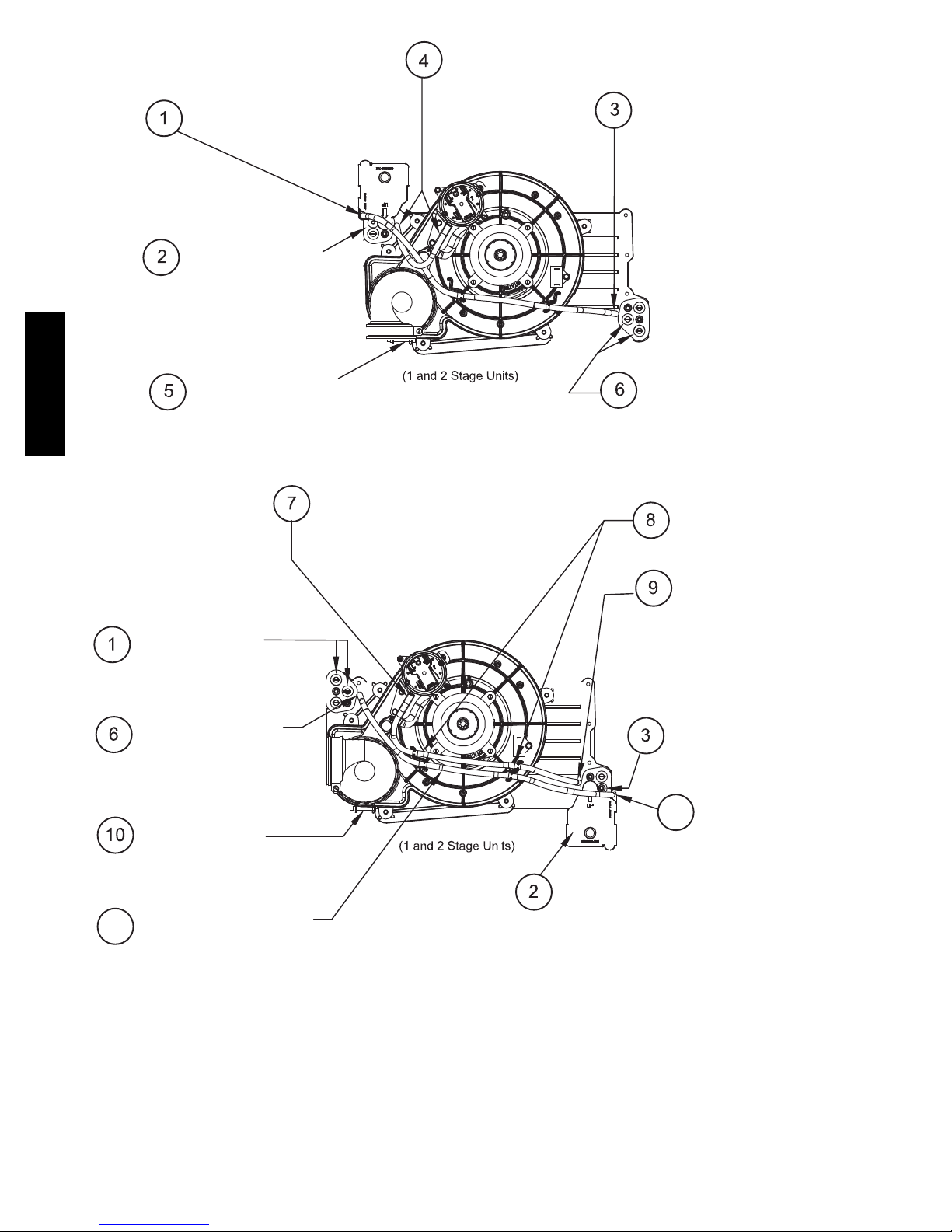
Condensate Trap -- Downflow Orientation.
When the furnace is installed in the downflow position, the
condensate trap will be initially located at the upper left corner of
the collector box, as received from the factory. See the top image
in Fig. 9. When the furnace is installed in the downflow
orientation, the condensate trap must be relocated for proper
condensate drainage. See the bottom image in Fig. 9.
To Relocate the Condensate Trap:
S Orient the furnace in the downflow position.
S Fig. 9 shows the condensate trap and tubing before and after
relocation. Refer to Fig. 9 to begin the trap conversion.
S Refer to Condensate Drain section for information how to install the
condensate drain.
Condensate Trap -- Horizontal Orientation.
When the furnace is installed in the horizontal right position, the
condensate trap will be initially located at the bottom of the collector
box, as received from the factory. See the top image in Fig. 10.
When the furnace is installed in the horizontal left position, the
condensate trap will be initially located at the top of the collector box,
as received from the factory. See the top image in Fig. 11. In both
cases the trap must be repositioned on the collector box for proper
condensate drainage. See the bottom images in Fig. 10 and 11.
A field--supplied, accessory Horizontal Installation Kit (trap
grommet) is required for all direct--vent horizontal installations (only).
The kit contains a rubber casing grommet designed to seal between
the furnace casing and the condensate trap. See Fig. 16.
NOTICE
The field--supplied, accessory horizontal drain trap grommet is
ONLY REQUIRED FOR DIRECT VENT APPLICATIONS.
It it NOT required for applications using single--pipe or
ventilated combustion air venting.
NOTICE
The condensate trap extends below the side of the casing in
the horizontal position. A minimum of 2--in. (51 mm) of
clearance is required between the casing side and the furnace
platform for the trap to extend out of the casing in the
horizontal position. Allow at least 1/4--in. per foot (20 mm
per meter) of slope down.
To Relocate the Condensate Trap:
S Remove the knockout in the casing for the condensate trap.
S Install the grommet in the casing when required for direct--vent
horizontal applications.
S Orient the furnace in the desired position.
S Allow for 2 in. (51 mm) of clearance underneath the furnace for the
condensate trap and drain line.
S Fig. 10 shows the condensate trap and tubing before and after
relocation in the horizontal right position.
S Fig. 11 shows the condensate trap and tubing before and after
relocation in the horizontal left position.
S Refer to the appropriate figure to begin the trap conversion.
S Refer to Condensate Drain section for information how to install the
condensate drain.
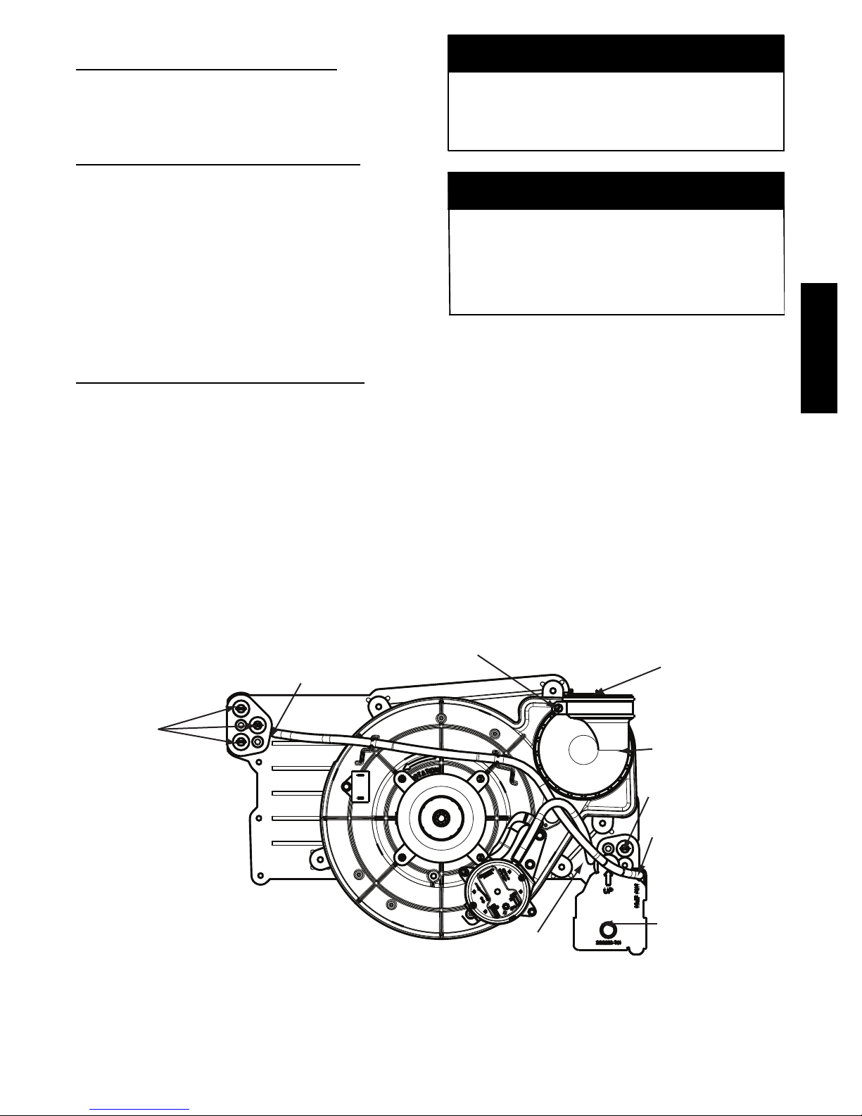
912SB
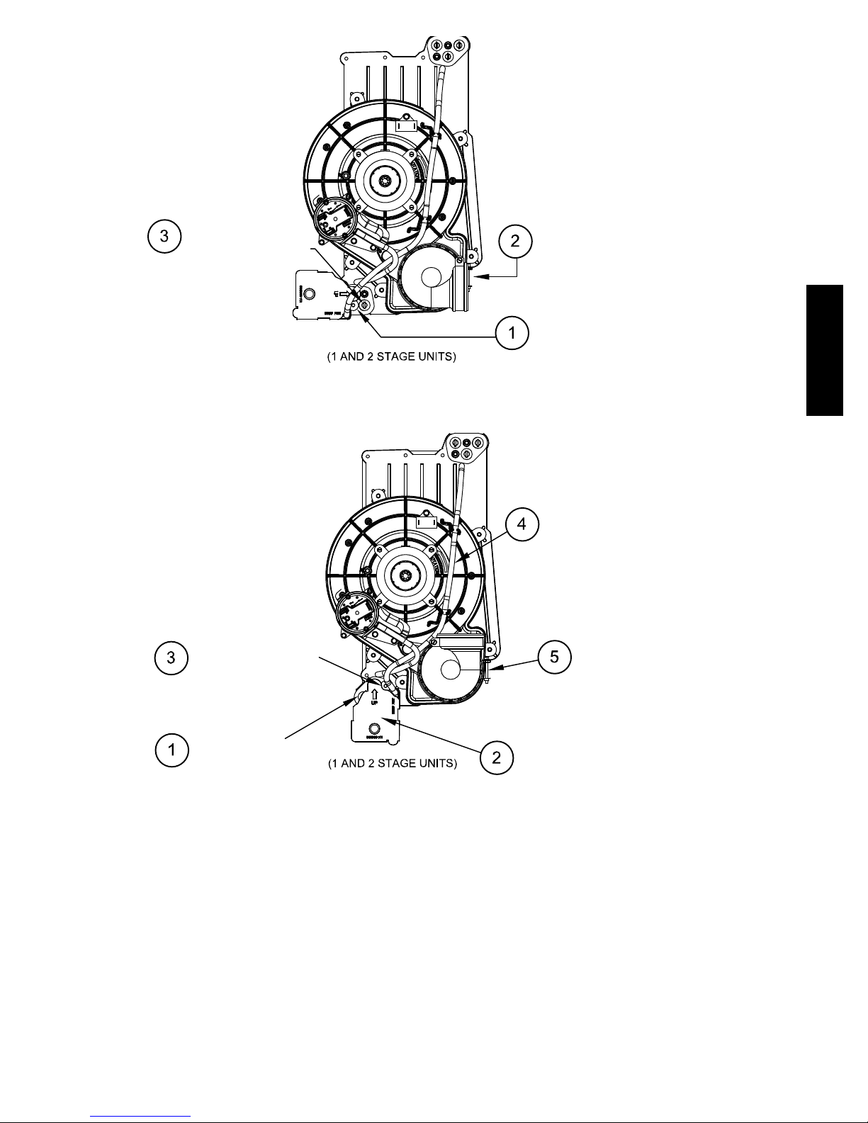
Collector Box
Plugs
Condensate Trap
Relief Port
Fig. 8 -- Upflow Trap Configuration
Vent Pipe Clamp
Pressure Switch
Port
UPFLOW TRAP CONFIGURATION
1 & 2 Stage Units
(Appearance may vary)
Vent Elbow Clamp
Vent Elbow
Collector Box
Plug
Condensate Trap
Relief Port
Condensate Trap
Outlet
A11307
13
Remove pressure switch tube from
front pressure switch and discard. A
new tube is shipped in the loose parts bag.
912SB
Remove relief tube from relief
port on condensate trap.
Remove the screw
that secures the trap
to the collector box and
remove trap.
Loosen clamp on inlet
to vent elbow.
Unconverted Factory Configuration as
Viewed in the Downflow Orientation
Connect the new pressure switch
tube from Loose Parts bag to
port on front pressure switch.
Remove tube from relief port.
Remove middle and bottom
plugs. DO NOT DISCARD.
Route tube through inducer
standïoffs to adjust position
of the tube.
Install the two plugs
previously removed
on the open ports
of the collector box.
Connect relief tube
to port on collector
box.
Rotate elbow to
desired position and
tighten clamp to
15 lb.ïin.
Slide tube in standïoffs
4
to adjust length.
Align condensate trap
over middle and bottom
ports of collector box.
Downflow Trap Configuration
Fig. 9 -- Downflow Trap Configuration
(Appearance may vary)
Trim excess tube.
Connect pressure switch
tube to port on collector
box.
Attach condensate trap
with screw to collector box.
Connect relief tube to
5
relief port on condensate
trap.
A11587
14
Remove plug from
collector box.
DO NOT DISCARD.
As Viewed in the Horizontal Right Orientation
NOTE: Remove knockout in
casing before reïinstalling the
condensate trap.
If alternate vent position
is required, loosen clamp
on inlet of vent elbow.
Remove the screw that secures
the trap to the collector box and
remove trap.
912SB
Unconverted Factory Configuration
Slide relief tube in standïoffs
to adjust length.
Attach condensate
trap with screw to
collector box.
Install plug on
open port of
collector box
Vent elbow shown in alternate
orientation. Tighten clamp on
inlet to vent elbow 15 lb.ïin.
Align trap over middle and
rightïhand port on collector box.
Horizontal Right Trap Configuration
A11573
Fig. 10 -- Horizontal Right Trap Configuration
(Appearance may vary)
15

If alternate vent position
5
is required, loosen clamp
on vent elbow inlet.
Remove the screw that secures the
condensate trap to the collector box
and remove trap.
Remove relief tube from
relief port on condensate
trap.
Remove front pressure
switch tube and discard.
A new tube is shipped in
the Loose Parts bag.
912SB
NOTE: Remove knockout in
casing before re-installing the
condensate trap.
Remove relief tube
from port on collector
box.
Rotate elbow to
9
desired position
and torque clamp
on inlet 15 lb.-in.
Slide relief tube in
stand-offs to adjust
length.
Remove middle and right
6
plug from collector box.
DO NOT DISCARD.
Unconverted Factory Trap Configuration
As Viewed in the Horizontal Left Orientation
Install two plugs previously
removed in open ports on
collector box.
Connect relief tube to port
on collector box.
Connect the new pressure switch
7
tube from Loose Parts bag to port
on front pressure switch.
Attach condensate
trap with screw to
collector box.
Align trap over middle
and right-hand port on
collector box.
Route pressure switch tube
underneath relief tube and
8
connect to port on
collector box.
Connect relief tube to relief
port on condensate trap.
Horizontal Left Trap Configuration
Fig. 11 -- Horizontal Left Configuration
(Appearance may vary)
16
A11574
CONDENSATE DRAIN CONNECTION
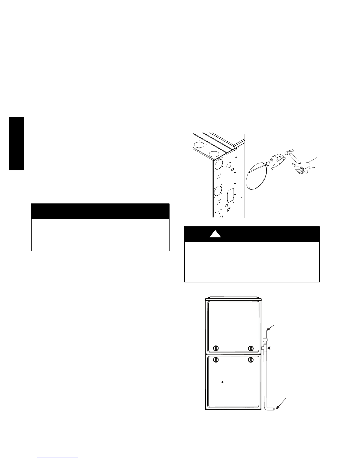
!
CAUTION
FROZEN AND BURST WATER PIPE HAZARD
Failure to protect against the risk of freezing may result in
property damage.
Special precautions MUST be made if installing furnace in an
area which may drop below freezing. This can cause improper
operation or damage to equipment. If furnace environment
has the potential of freezing, the drain trap and drain line must
be protected. The use of accessory drain trap heaters, electric
heat tape and/or RV antifreeze is recommended for these
installations.
!
CAUTION
PROPERTY DAMAGE HAZARD
Failure to follow this caution may result in burst water pipes
and/or property damage.
If a condensate pump is installed, a plugged condensate drain
or a failed pump may cause the furnace to shut down. Do not
leave the home unattended during freezing weather without
turning off water supply and draining water pipes or otherwise
protecting against the risk of frozen pipes.
DO NOT trap the drain line in any other location than at the
condensate drain trap supplied with the furnace. If possible, DO
NOT route the drain line where it may freeze. The drain line must
terminate at an inside drain to prevent freezing of the condensate
and possible property damage.
Special precautions MUST be made if installing furnace in an area
which may drop below freezing. This can cause improper
operation or damage to the equipment. If the furnace environment
has the potential of freezing, the drain trap and drain line must be
protected. A self--regulating, shielded and waterproof heat tape
rated at 3 to 6 watt per foot (10 to 20 watt per meter) at 115 volt,
40_F(4_C) may be used to help provide freeze protection. Wrap
the drain trap and drain line with the heat tape and secure with
appropriate plastic ties. Follow the heat tape manufacturer’s
recommendations. Prime the trap before furnace operation.
Upflow/Downflow Orientation
In the Upflow or Downflow orientation, the condensate trap is
inside the furnace casing. The condensate drain must be routed
from the trap through the furnace casing. The condensate drain can
be routed through the left or right side of the casing. (The left or
right side is as you are viewing/facing the furnace from the front.)
The furnace condensate drain can be connected to the indoor coil
condensate drain, humidifier or auxiliary drain traps as shown in
Fig. 13.
NOTE: On narrower casings, it may be easier to remove the
condensate trap, connect the drain line components and re-install
the condensate trap. Read the steps thoroughly to familiarize
yourself with the required steps.
For Right Side Condensate Drain:
1. Remove the 7/8--in. knock--out from the right side of the
casing. See Fig. 12 for suggested knockout removal technique.
2. Remove the pre--formed rubber drain elbow and two spring
clamps from the loose parts bag.
3. Slide a spring clamp 1--inch (25 mm) down the plain end
(the end without the formed grommet) of the drain elbow.
4. From inside the casing, insert the formed grommet end of
the elbow through the 7/8--in. knockout in the casing.
5. Pull the grommet through the casing from the outside until
it is seated in the knockout
6. Attach the plain end of the drain elbow to the outlet stub on
the drain trap. Secure the drain elbow to the trap with the
spring clamp.
The remaining drain line can be constructed from field supplied
1/2--in. CPVC or 3/4--in. PVC pipe, in compliance with local
building codes. A factory--supplied 1/2--in. CPVC to 3/4--in. PVC
adapter is supplied in the loose parts bag for use as required.
7. Install the adapter or connect the 1/2--in. CPVC pipe by
sliding a spring clamp over the open end of the grommet on
the outside the furnace casing.
8. Open the spring clamp and insert the long end of the
adapter or the 1/2--in. CPVC pipe into the outlet stub on the
drain tube.
9. Connect additional condensate piping to a code--approved
drain, or to a condensate pump approved for use with acidic
furnace condensate and compatible with mineral and
vegetable oils, such as canola oil.
Allow at least 1/4-in. per foot (20 mm per meter) of slope down
and away from the furnace in horizontal sections of drain line.
TIP FROM CONTRACTORS: Contractors have found that
temporarily removing the inducer assembly in upflow applications
while performing the steps, below, makes upflow left--side drain
connections easier.
For Left Side Condensate Drain Connection:
1. For left side condensate drainage, the drain line is routed
from the condensate trap, behind the inducer (upflow) or
gas valve (downflow) and out through the left side of the
furnace casing. A pre-formed 1/2--in. CPVC “Z-pipe” is
provided with the furnace. The Z-pipe is long enough to
extend across the casing for drain connections.
2. Locate the Z-pipe. Remove the pre-formed drain elbow and
four spring clamps from the loose parts bag.
3. The Z-pipe is connected to the condensate trap and the
outside of the furnace by modifying the formed rubber
drain elbow as shown in Fig. 15.
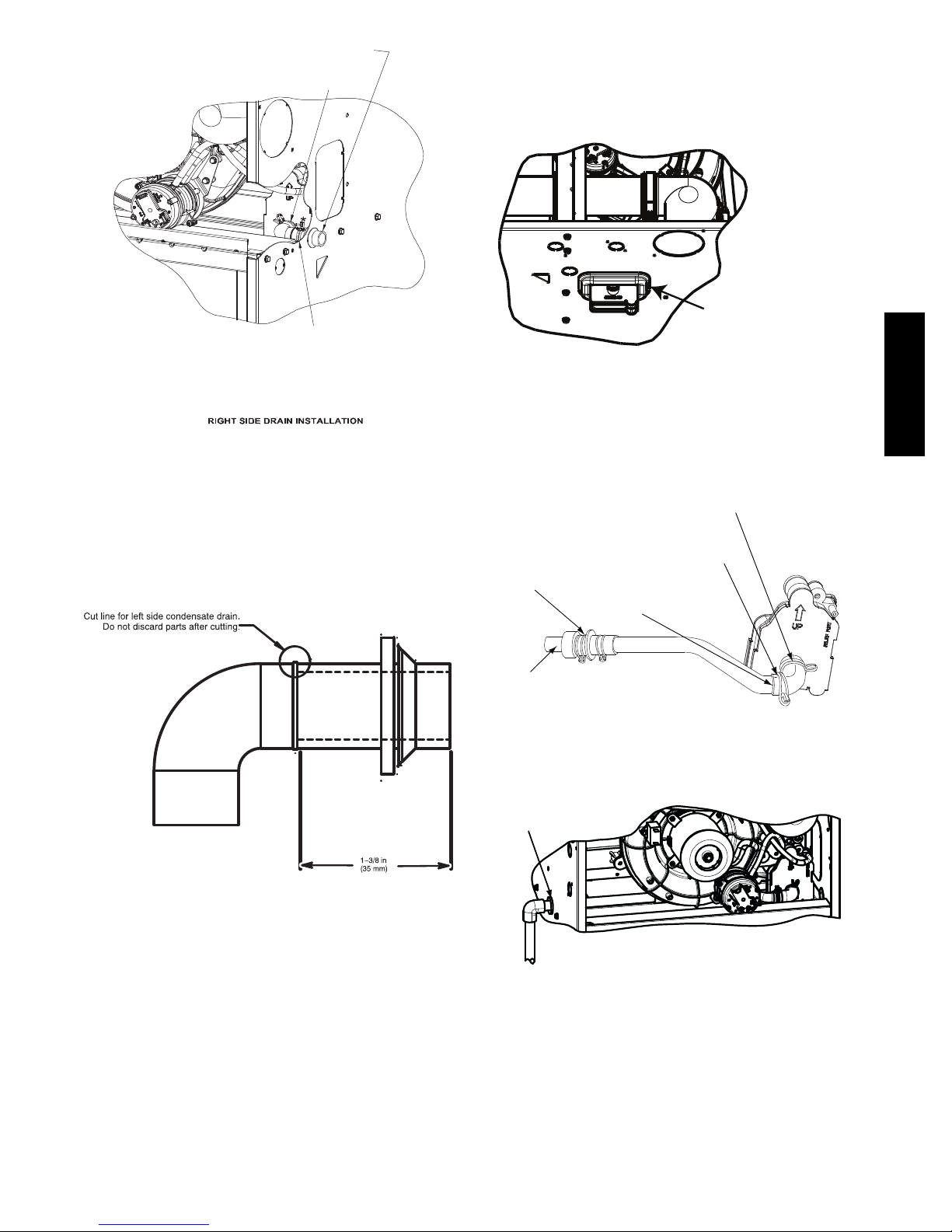
4. Remove the formed grommet from the rubber drain elbow
by cutting the elbow along the vertical line located about
1--3/8 in. (35 mm) away from the formed grommet. See Fig.
15. DO NOT DISCARD THE FORMED GROMMET
OR THE RUBBER ELBOW. Both of these pieces will be
used.
Assemble and route the drain line to the opposite side of the
furnace as detailed below:
5. Remove the knock-out from the left side of the casing. See
Fig. 12 for suggested knockout removal technique.
6. From the outside of the casing, insert the angled end of the
Z-pipe through drain hole in the left side of the casing and
behind the inducer or gas valve. Allow the Z-pipe to
temporarily rest on the blower shelf (upflow) or burner box
(downflow). (NOTE: When the inducer housing has been
removed to ease installation in upflow applications, this step
is not needed.)
7. After inserting the Z pipe through the casing, slide a spring
clamp over each end of the Z pipe.
8. From inside the casing, insert the short end of the formed
grommet cut from the rubber drain elbow through the
7/8-in. drain knockout in the casing.
9. Pull the grommet through the casing from the outside until
it is seated in the knockout.
10. Align the Z-pipe with the long end of the grommet inside
the furnace and insert slightly. The angled end of the tube at
912SB
17
the other side of the casing should be facing the front of the
furnace.
11. Slide a spring clamp over the end of the remaining rubber
drain elbow.
12. Attach the drain elbow to the angled end of Z-pipe and the
drain trap outlet stub. Adjust the length of Z-pipe inserted
into the grommet at the opposite side of the furnace as
necessary for proper fit and positioning. In both upflow and
downflow orientations, the Z-pipe should NOT be resting
on any sheet metal parts.
13. Secure the rubber elbow to the drain trap and the Z-pipe
with spring clamps.
14. Secure the grommet to the Z-pipe with the spring clamp.
The remaining drain line can be constructed from field supplied
1/2--in. CPVC or 3/4--in. PVC pipe, in compliance with local
building codes. A factory-supplied 1/2--in. CPVC to 3/4--in. PVC
adapter is supplied in the loose parts bag for use as required.
15. Install the adapter or connect the 1/2--in. CPVC pipe by
sliding a spring clamp over the open end of the grommet on
the outside the furnace casing.
912SB
16. Open the spring clamp and insert the long end of the
adapter or the 1/2--in. CPVC pipe into the outlet stub on the
drain tube.
17. Connect additional condensate piping to a code-approved
drain, or to a condensate pump approved for use with acidic
furnace condensate and compatible with mineral and
vegetable oils, such as canola oil.
Allow at least 1/4-in. per foot (20 mm per meter) of slope down
and away from the furnace in horizontal sections of drain line.
7. The remaining drain line can be constructed from field-supplied 1/2--in. CPVC or 3/4--in. PVC pipe, in compliance
with local building codes. A factory--supplied 1/2--in.
CPVC to 3/4--in. PVC adapter is supplied in the loose parts
bag for use as required.
8. Install the adapter or connect the 1/2--in. CPVC pipe by
sliding a spring clamp over the open end of the elbow or
grommet on the outside the furnace casing.
9. Open the spring clamp and insert the long end of the
adapter or the 1/2--in. CPVC pipe into the outlet stub on the
drain tube.
10. Connect additional condensate piping to a code--approved
drain, or to a condensate pump approved for use with acidic
furnace condensate and compatible with mineral and
vegetable oils, such as canola oil.
Allow at least 1/4-in. per foot (20 mm per meter) of slope down
and away from the furnace in horizontal sections of drain line.
NOTICE
The field--supplied, accessory horizontal drain trap grommet is
ONLY REQUIRED FOR DIRECT VENT APPLICATIONS.
It is NOT required for applications using single--pipe or
ventilated combustion air venting.
TIP FROM CONTRACTORS: When installing the furnace
horizontally, use the entire drain elbow (that is, do NOT cut as
shown in Fig. 15 to connect the trap to the drain line. This helps to
prevent bumps and shocks to the drain line from damaging the
furnace drain trap. Avoid misalignment of the drain pipe which
may cause kinks in the elbow.
Horizontal Orientation
1. The condensate trap outlet extends 2--in. (51 mm) below the
furnace casing. Leave enough clearance between the furnace
and the furnace platform for the trap.
2. To allow for servicing the trap, the condensate drain elbow
in the loose parts bag can be used to make a coupler to
allow for future service of the condensate trap and drain
line.
3. Remove the knock-out for the condensate trap in the side of
the casing.
4. Install the drain trap grommet in the casing if required for
direct--vent applications. If necessary, remove the trap,
install the grommet and re-install the trap.
5. Remove the pre-formed rubber drain elbow, and two spring
clamps from the loose parts bag.
6. Connect the full or modified elbow and/or grommet to the
outlet of the condensate trap with one spring clamp. Avoid
misalignment of the drain pipe which may cause kinks in
the elbow or grommet.
!
CAUTION
CUT HAZARD
Failure to follow this caution may result in personal injury.
Sheet metal parts may have sharp edges or burrs. Use care
and wear appropriate protective clothing, safety glasses and
gloves when handling parts, and servicing furnaces.
L12F019B
Fig. 12 -- Knockout Removal
OPEN STAND
PIPE FOR
A/C OR
HUMIDIFIER
DRAIN
TEE
TO OPEN
DRAIN
Fig. 13 -- Example of Field Drain Attachment
A11276
18
INSTALL CLAMPS ON DRAIN TUBE
ATTACH DRAIN TUBE TO CONDENSATE
DRAIN TRAP
PULL DRAIN STUB
THROUGH CASING
OPEN SPRING CLAMP
INSERT FACTORYïSUPPLIED 1/2ïIN. CPVC
TO 3/4ïIN. PVC ADAPTER OR 1/2ïIN. CPVC PIPE
*CLAMP MAY BE LOCATED ON OUTSIDE OF DRAIN
TUBE
NOTE: Trap grommet is required only for direct-vent
applications.
Remove knockout.
Install grommet before
relocating condensate
trap.
912SB
Fig. 14 -- Formed Rubber Drain Grommet
A11342A
Fig. 16 -- Horizontal Drain Trap Grommet
Attach elbow to condensate trap
Cut formed end off
Formed end of
grommet
Factory supplied 1/2ïin. CPVC to
3/4ïin. PVC adapter
TRAP, DRAIN ELBOW WITH DISCHARGE PIPE
Formed end of grommet
Open spring clamp. Insert
1/2ïin. to 3/4ïin. CPVC to
PVC adapter or 1/2ïin.
CPVC pipe
condensate drain
elbow
Connect short end
of “Z” pipe to modified
drain elbow
A11582
s
Modified drain elbow connect to
condensate trap and “Z” pipe
Fig. 15 -- Modify Rubber Drain Elbow
A11581
NOTE: Remove Inducer Housing for easier access, if desired.
LEFT SIDE DRAIN ROUTED BEHIND INDUCER
L12F015
Fig. 17 -- Drain Trap Connection and Routing
(Appearance may vary)
19

INSTALLATION
NOTICE
This furnace is certified to leak 2% or less of nominal air
conditioning CFM delivered when pressurized to 1--in. water
column with all present air inlets, including bottom closure in
upflow and horizontal applications, air outlets, and plumbing
and electrical ports sealed.
Upflow Installation
NOTE: The furnace must be pitched as shown in Fig. 24 for
proper condensate drainage.
Supply Air Connections
For a furnace not equipped with a cooling coil, the outlet duct shall
be provided with a removable access panel. This opening shall be
accessible when the furnace is installed and shall be of such a size
that the heat exchanger can be viewed for possible openings using
light assistance or a probe can be inserted for sampling the air
stream. The cover attachment shall prevent leaks.
912SB
Connect supply--air duct to flanges on furnace supply--air outlet.
Bend flange upward to 90_ with wide duct pliers. See Fig. 21.
The supply--air duct must be connected to ONLY the furnace
supply--outlet--air duct flanges or air conditioning coil casing
(when used). DO NOT cut main furnace casing side to attach
supply air duct, humidifier, or other accessories. All supply side
accessories MUST be connected to duct external to furnace main
casing.
Return Air Connections
!
WARNING
FIRE HAZARD
A failure to follow this warning could cause personal injury,
death and/or property damage.
Never connect return--air ducts to the back of the furnace.
Follow instructions below.
The return--air duct must be connected to bottom, sides (left or
right), or a combination of bottom and side(s) of main furnace
casing. Bypass humidifier may be attached into unused return air
side of the furnace casing. See Fig. 25, 26, and 27.
Bottom Return Air Inlet
These furnaces are shipped with bottom closure panel installed in
bottom return--air opening. Remove and discard this panel when
bottom return air is used. To remove bottom closure panel, perform
the following:
1. Tilt or raise furnace and remove 4 screws holding bottom
plate. See Fig. 23.
2. Remove bottom plate.
3. Remove bottom closure panel.
4. Reinstall bottom plate and screws.
Side Return Air Inlet
These furnaces are shipped with bottom closure panel installed in
bottom return--air opening. This panel MUST be in place when
only side return air is used.
NOTE: Side return--air openings can be used in UPFLOW and
some HORIZONTAL configurations. Do not use side return--air
openings in DOWNFLOW configuration. See Fig. 25, 26, and 27.
Leveling Legs (If Desired)
In upflow position with side return inlet(s), leveling legs may be
used. See Fig. 22. Install field--supplied, 5/16 x 1--1/2 in. (8 x 38
mm) (max) corrosion--resistant machine bolts, washers and nuts.
NOTE: Bottom closure must be used when leveling legs are used.
It may be necessary to remove and reinstall bottom closure panel to
install leveling legs. To remove bottom closure panel, see Item 1 in
Bottom Return Air Inlet section in Step 1 above.
To install leveling legs:
1. Position furnace on its back. Locate and drill a hole in each
bottom corner of furnace.
2. For each leg, install nut on bolt and then install bolt with
nut in hole. (Install flat washer if desired.)
3. Install another nut on other side of furnace base. (Install flat
washer if desired.)
4. Adjust outside nut to provide desired height, and tighten inside nut to secure arrangement.
5. Reinstall bottom closure panel if removed.
Downflow Installation
NOTE: The furnace must be pitched as shown in Fig. 24 for
proper condensate drainage.
Supply Air Connections
NOTE: For downflow applications, this furnace is approved for
use on combustible flooring when any one of the following 3
accessories are used:
S Special Base, KGASB
S Cased Coil Assembly Part No. CNPV, CNRV, CAP, or CAR
S Coil Box Part No. KCAKC
1. Determine application being installed from Table 8.
2. Construct hole in floor per Table 8 and Fig. 20.
3. Construct plenum to dimensions specified in Table 8 and
Fig. 20.
4. Install special base coil assembly or coil box as shown in
Fig. 20.
NOTE: It is recommended that the perforated supply--air duct
flanges be completely removed from furnace when installing the
furnace on a factory--supplied cased coil or coil box. To remove the
supply--air duct flange, use wide duct pliers or hand seamers to
bend flange back and forth until it breaks off. Be careful of sharp
edges. See Fig. 21.
!
CAUTION
CUT HAZARD
Failure to follow this caution may result in personal injury.
Sheet metal parts may have sharp edges or burrs. Use care
and wear appropriate protective clothing, safety glasses and
gloves when handling parts, and servicing furnaces.
Connect supply--air duct to supply--air outlet on furnace. Bend
flange inward past 90_ with wide duct pliers See Fig. 21. The
supply--air duct must be connected to ONLY the furnace supply
outlet or air conditioning coil casing (when used). When installed
on combustible material, supply--air duct must be connected to
ONLY the factory--approved accessory subbase, or a
factory--approved air conditioning coil casing. DO NOT cut main
furnace casing to attach supply side air duct, humidifier, or other
accessories. All supply side accessories MUST be connected to
duct external to furnace casing.
20
Return Air Connections
!
WARNING
FIRE HAZARD
A failure to follow this warning could cause personal injury,
death and/or property damage.
Never connect return--air ducts to the back of the furnace.
Follow instructions below.
The return--air duct must be connected to return--air opening
(bottom inlet). DO NOT cut into casing sides (left or right).
Bypass humidifier connections should be made at ductwork or coil
casing sides exterior to furnace. See Fig. 26.
Bottom Return Air Inlet
These furnaces are shipped with bottom closure panel installed in
bottom return--air opening. Remove and discard this panel when
bottom return air is used. To remove bottom closure panel, perform
the following:
1. Tilt or raise furnace and remove 4 screws holding bottom
plate. See Fig. 23.
2. Remove bottom plate.
3. Remove bottom closure panel.
4. Reinstall bottom plate and screws.
Horizontal Installation
NOTE: The furnace must be pitched forward as shown in Fig. 24
for proper condensate drainage.
!
WARNING
FIRE, EXPLOSION, AND CARBON MONOXIDE
POISONING HAZARD
Failure to follow this warning could result in personal
injury, death, or property damage.
Do not install the furnace on its back or hang furnace with
control compartment facing downward. Safety control
operation will be adversely affected. Never connect
return--air ducts to the back of the furnace.
!
CAUTION
MINOR PROPERTY HAZARD
Failure to follow this caution may result in minor property
damage.
Local codes may require a drain pan under entire furnace and
condensate trap when a condensing furnace is used in an attic
application or over a finished ceiling.
The furnace can be installed horizontally in an attic or crawlspace
on either the left--hand (LH) or right--hand (RH) side. The furnace
can be hung from floor joists, rafters or trusses or installed on a
non--combustible platform, blocks, bricks or pad.
Platform Furnace Support
Construct working platform at location where all required furnace
clearances are met. See Table 2 and Fig. 28. For furnaces with
1--in. (25 mm) clearance requirement on side, set furnace on
non--combustible blocks, bricks or angle iron. For crawlspace
installations, if the furnace is not suspended from the floor joists,
the ground underneath furnace must be level and the furnace set on
blocks or bricks.
Suspended Furnace Support
The furnace must be supported under the entire length of the
furnace with threaded rod and angle iron. See Fig. 29. Secure
angle iron to bottom of furnace as shown.
Roll--Out Protection
Provide a minimum 12--in. x 22--in. (305 x 559 mm) piece of sheet
metal for flame roll--out protection in front of burner area for
furnaces closer than 12--in. (305 mm) above the combustible deck
or suspended furnaces closer than 12--in. (305 mm) to joists. The
sheet metal MUST extend underneath the furnace casing by 1--in.
(25 mm) with the door removed.
The bottom closure panel on furnaces of widths 17--1/2--in. (445
mm) and larger may be used for flame roll--out protection when
bottom of furnace is used for return air connection. See Fig. 28 for
proper orientation of roll--out shield.
Supply Air Connections
For a furnace not equipped with a cooling coil, the outlet duct shall
be provided with a removable access panel. This opening shall be
accessible when the furnace is installed and shall be of such a size
that the heat exchanger can be viewed for possible openings using
light assistance or a probe can be inserted for sampling the air
stream. The cover attachment shall prevent leaks.
Connect supply--air duct to flanges on furnace supply--air outlet.
Bend flange upward to 90_ with wide duct pliers. See Fig. 21.
The supply--air duct must be connected to ONLY the furnace
supply--outlet--air duct flanges or air conditioning coil casing
(when used). DO NOT cut main furnace casing side to attach
supply air duct, humidifier, or other accessories. All supply side
accessories MUST be connected to duct external to furnace main
casing.
Return Air Connections
The return--air duct may be connected to bottom of the furnace.
The side of casing that faces downward may also be used for return
air connection. A combination of the bottom and downward
facing side may also be used. The upward facing side of the casing
cannot be used as a return air connection. See Fig. 27.
Bottom Return Air Inlet
These furnaces are shipped with bottom closure panel installed in
bottom return--air opening. Remove and discard this panel when
bottom return air is used. To remove bottom closure panel, perform
the following:
1. Tilt or raise furnace and remove 4 screws holding bottom
plate. See Fig. 23.
2. Remove bottom plate.
3. Remove bottom closure panel.
4. Reinstall bottom plate and screws.
Side Return Air Inlet
These furnaces are shipped with bottom closure panel installed in
bottom return--air opening. This panel MUST be in place when
side return air inlet(s) are used without a bottom return air inlet.
Not all horizontal furnaces are approved for side return air
connections See Fig. 27.
Filter Arrangement
!
WARNING
FIRE, CARBON MONOXIDE AND POISONING
HAZARD
Failure to follow this warning could result in fire, personal
injury or death.
Never operate a furnace without a filter or filtration device
installed. Never operate a furnace with filter or filtration
device access doors removed.
912SB
21
There are no provisions for an internal filter rack in these furnaces.
An external filter is required and is purchased separately. A field
supplied accessory air cleaner may also be used in place of the filter
rack.
For upflow applications, the filter can be installed on either side of
the furnace, the bottom of the furnace or any combination of side
and bottom of the furnace. See Fig. 18, 19, and 25.
For downflow applications, the filter rack (or field supplied
accessory air cleaner) must only be connected to the bottom
opening on the furnace. See Fig. 19 and 26.
For horizontal applications, the filter rack (or field supplied
accessory air cleaner) can be connected to the bottom opening on
the furnace. For side return use in the horizontal position, refer to
Fig. 27. If both side and bottom openings are used in Fig. 27, each
opening used will require a filter.
A filter rack or any field supplied accessory air cleaner can also be
installed in the common return duct prior to entering the return air
opening in any orientation.
Refer to the instructions supplied with filter rack or accessory air
filter for additional assembly and installation options.
See Table 7 for filter size details.
912SB
Filter and Return Duct Sizing
Pressure drop must be taken into account when sizing filters, filter
racks, IAQ devices, and associated system ductwork. See Table 5
for a comparison of Pressure Drop (initial/clean resistance to
airflow) versus Airflow for a variety of filter media types and sizes.
These are representative numbers. Consult the filter or IAQ device
manufacturers’ specification sheet for performance data for a
particular filter media or IAQ device.
Design the filter and associated ductwork for the best match of
pressure drop versus filter size. Best practice usually chooses filter
systems with pressure drops under 0.2 in. W.C. (50 Pa), with the
best blower electrical efficiency and system airflow performance
occurring with filter pressure drops under 0.1 in. W.C. (25 Pa).
Due to the relatively high pressure drops of 1--in. (25 mm) thick
after--market filter media, it is recommended that the filtration
system be designed for at least 2--in. (51 mm) thick media.
TIPS FROM CONTRACTORS: Install a media cabinet capable
of incorporating a 4--in. (102 mm) thick media filter. This allows
room for future upgrades to other IAQ devices.
NOTICE
Design the duct system FIRST to determine how much
pressure drop may be allowed in the filter system. See the Air
Ducts section. Excessive filter pressure drop often
compromises system airflow and duct performance, causes
inadequate airflow to the furthest ends of the duct system, as
well as causes excess noise and higher than anticipated
electrical consumption.
Provide duct transitions, as required, to smoothly transition airflow
from the return duct system to the filter (or IAQ device) to the
furnace when the dimensions of the ductwork or furnace return air
opening do not match the required filter or IAQ device dimensions.
See the instructions supplied with factory--accessory duct adapters.
22
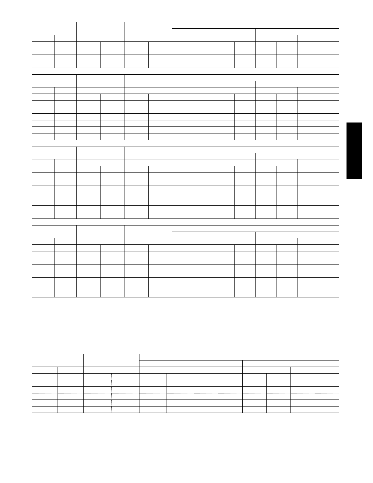
Table 5 – Filter Media Pressure Drop (Clean) Versus Airflow -- In. W.C. (Pa)
14 x 25 Filter
(356 x 635 mm)
CFM L/s (1-in. / 2.5 cm) (4-in. / 10 cm) (1-in. / 2.5 cm) (2-in. / 5 cm) (1-in. / 2.5 cm) (2-in. / 5 cm)
600 (283) 0.04 (12) 0.05 (12) 0.07 (17) 0.10 (26) 0.24 (60) 0.16 (40)
800 (378) 0.06 (15) 0.07 (19) 0.10 (25) 0.15 (39) 0.34 (85) 0.23 (59)
1000 (472) 0.07 (18) 0.10 (27) 0.13 (34) 0.21 (52) - - 0.32 (81)
1200 (566) 0.08 (20) 0.14 (36) 0.17 (43) 0.27 (68) - - - -
Factory-Accessory
Washable
Factory-Accessory
Media*
Representative After-Market Filter Media*
Fiberglass* Pleated*
16 x 25 Filter
(406 x 635 mm)
CFM L/s (1-in. / 2.5 cm) (4-in. / 10 cm) (1-in. / 2.5 cm) (2-in. / 5 cm) (1-in. / 2.5 cm) (2-in. / 5 cm)
600 (283) 0.04 (10) 0.05 (13) 0.06 (15) 0.09 (22) 0.20 (51) 0.13 (34)
800 (378) 0.05 (13) 0.07 (18) 0.08 (21) 0.13 (32) 0.29 (72) 0.20 (49)
1000 (472) 0.06 (16) 0.11 (28) 0.11 (28) 0.17 (43) - - 0.27 (67)
1200 (566) 0.07 (18) 0.15 (37) 0.14 (36) 0.22 (56) - - - 1400 (661) 0.08 (21) 0.19 (48) 0.18 (45) 0.28 (70) - - - 1600 (755) 0.09 (23) 0.24 (60) 0.21 (54) - - - - - 1800 (850) 0.10 (25) - - 0.26 (64) - - - - - -
20 x 25 Filter
(508 x 635 mm)
CFM (L/s) (1 -in. / 2.5 cm) (4 -in. / 10 cm) (1 -in. / 2.5 cm) (2-in. / 5 cm) (1-in. / 2.5 cm) (2-in. / 5 cm)
800 (378) 0.04 (11) 0.05 (12) 0.06 (16) 0.09 (24) 0.22 (55) 0.15 (37)
1000 (472) 0.05 (13) 0.07 (18) 0.08 (21) 0.13 (32) 0.29 (72) 0.20 (49)
1200 (566) 0.06 (15) 0.09 (22) 0.11 (27) 0.16 (41) - - 0.25 (63)
1400 (661) 0.07 (17) 0.12 (31) 0.13 (33) 0.20 (51) - - 0.31 (79)
1600 (755) 0.08 (19) 0.15 (38) 0.16 (40) 0.24 (61) - - - 1800 (850) 0.08 (21) 0.18 (47) 0.18 (47) 0.29 (73) - - - 2000 (944) 0.09 (23) 0.22 (56) 0.21 (54) - - - - - 2200 (1038) 0.09 (24) 0.26 (66) 0.25 (62) - - - - - -
25 x 25 Filter
(635 x 635 mm)
CFM L/s (1-in. / 2.5 cm) (4-in. / 10 cm) (1-in. / 2.5 cm) (2-in. / 5 cm) (1-in. / 2.5 cm) (2-in. / 5 cm)
800 (378) 0.03 (9) 0.03 (8) 0.05 (12) 0.07 (18) 0.17 (43) 0.11 (28)
1000 (472) 0.04 (11) 0.05 (12) 0.06 (16) 0.09 (24) 0.22 (55) 0.15 (37)
1200 (566) 0.05 (13) 0.07 (17) 0.08 (20) 0.12 (31) 0.27 (68) 0.18 (47)
1400 (661) 0.06 (15) 0.09 (23) 0.10 (24) 0.15 (38) - - 0.23 (58)
1600 (755) 0.06 (16) 0.12 (31) 0.11 (29) 0.18 (45) - - 0.28 (69)
1800 (850) 0.07 (18) 0.14 (35) 0.13 (34) 0.21 (53) - - - 2000 (944) 0.08 (19) 0.16 (41) 0.16 (39) 0.24 (61) - - - 2200 (1038) 0.08 (21) 0.19 (49) 0.18 (45) 0.28 (70) - - - -
Factory-Accessory
Washable
Factory-Accessory
Washable
Factory-Accessory
Washable
Factory-Accessory
Media*
Factory-Accessory
Media*
Factory-Accessory
Media*
Representative After-Market Filter Media*
Fiberglass* Pleated*
Representative After-Market Filter Media*
Fiberglass* Pleated*
Representative After-Market Filter Media*
Fiberglass* Pleated*
912SB
If the filter size that you are looking for is not contained in Table 5, refer to Table 6 for a comparison of Pressure Drop (initial/clean resistance
to airflow) versus Face Velocity for a variety of filter media types.
The following equations relate Face Velocity (FPM), Filter Area and Airflow (CFM):
Filter Face Velocity = Airflow / Filter Area
Minimum Filter Area = Rated System Airflow / Maximum Filter Face Velocity
Table 6 – Filter Media Pressure Drop (Clean) Versus Face Velocity-- In. W.C. (Pa)
Face Velocity
FPM (m/s) (1-in. / 2.5 cm) (1-in. / 2.5 cm) (2-in. / 5 cm) (1-in. / 2.5 cm) (2-in. / 5 cm)
200 (1) 0.04 (10) 0.05 (13) 0.08 (20) 0.18 (47) 0.12 (31)
300 (1.5) 0.05 (14) 0.09 (22) 0.13 (34) 0.30 (75) 0.21 (52)
400 (2) 0.07 (17) 0.13 (32) 0.20 (50) - - 0.31 (78)
500 (2.5) 0.08 (21) 0.18 (44) 0.27 (69) - - - 600 (3) 0.09 (23) 0.23 - - - - - - 700 (3.6) 0.10 (26) 0.29 - - - - - - -
Factory-Accessory
Washable
Representative After-Market Filter Media*
Fiberglass* Pleated*
23
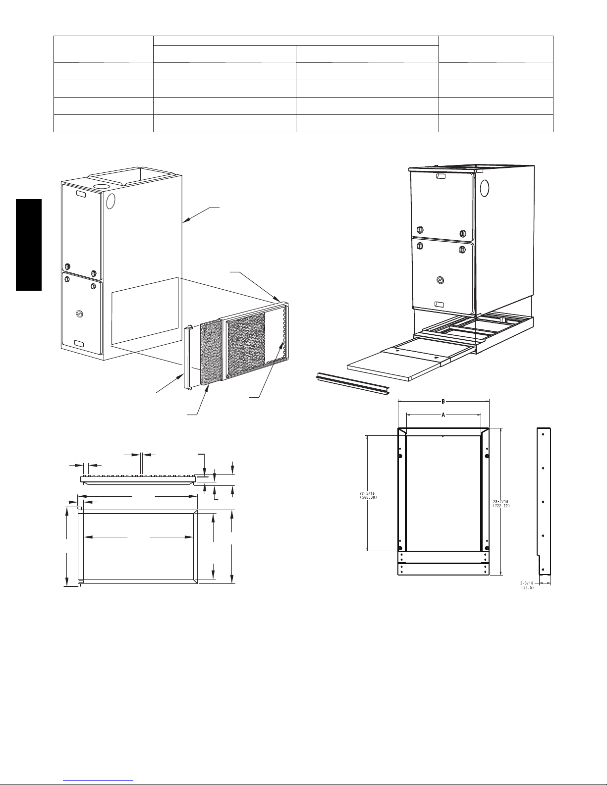
Table 7 – Air Filter Selection and Duct Sizing -- In. (mm)
FURNACE CASING WIDTH
14---3/16{ (360)
17---1/2 (445)
21 (533)
24---1/2 (622)
* Recommended to maintain air filter f ace velocity. See Product Data for part nu mber.
{ Not all families have these models.
SIDE
RETURN
16 x 25 x 3/4
(406 x 635 x 19)
16 x 25 x 3/4
(406 x 635 x 19)
16 x 25 x 3/4
(406 x 635 x 19)
16 x 25 x 3/4
(406 x 635 x 19)
FURNACE
FILTER SIZE
BOTTOM
RETURN
14 x 25 x 3/4
(356 x 635 x 19)
16 x 25 x 3/4
(406 x 635 x 19)
20 x 25 x 3/4
(508 x 635 x 19)
24 x 25 x 3/4
(610 x 635 x 19)
FILTER TYPE
Wash able*
Wash able*
Wash able*
Wash able*
912SB
17
(435 mm)
FILTER
FRAME
DOOR
FILTER
(FIELD SUPPLIED)
(10 mm)
1
25
(638 mm)
(587 mm)
1
/
23
3
TABS
/
8”
8”
(32 mm)
1
/
4”
1
(TYP.)
1
/
4”
1
(32 mm)
1
/
8”
OPENING
1
/
/
8”
2”
(13 mm)
14
(368 mm)
OPENING
TABS
3
(60 mm)
/
2
8”
3
/
(19 mm)
4”
1
/
(410 mm)
16
8”
1
/
2”
Fig. 18 -- Accessory Side Filter Rack
A11091
A11095
Fig. 19 -- Accessory Bottom Filter
24
 Loading...