

Bryant 619PHA Series, 619PHAQ18XA3, 619PHAQ24XA3, 619PHAQ09XA3, 619PHAQ12XA3 Service Manual
Page 1
!
619PHA
High Wall Ductless System
Sizes 09 to 24
Service Manual
TABLE OF CONTENTS
PAGE
SAFETY CONSIDERATIONS.......................................................1
INTRODUCTION............................................................................1
MODEL NUMBER NOMENCLATURE .......................................2
SPECIFICATIONS..........................................................................3
DIMENSIONS ................................................................................. 4
CLEARANCES................................................................................6
ELECTRICAL DATA ..................................................................... 7
WIRING...........................................................................................7
CONNECTION DIAGRAM............................................................ 8
WIRING DIAGRAM.......................................................................9
FAN AND MOTOR SPECIFICATIONS........................................11
REFRIGERATION CYCLE DIAGRAM........................................11
REFRIGERANT LINES..................................................................12
SYSTEM EVACUATION AND CHARGING...............................12
OPERATION MODES AND FUNCTIONS...................................13
ERROR DIAGNOSIS AND TROUBLESHOOTING WITHOUT ER-
ROR CODE...................................................................................... 20
QUICK MAINTENANCE BY ERROR CODE..............................24
TROUBLESHOOTING BY ERROR CODE.................................. 25
DIAGNOSIS AND SOLUTION......................................................27
DISASSEMBLY INSTRUCTIONS ................................................ 40
APPENDICES..................................................................................64
SAFETY CONSIDERATIONS
Installing, starting up, and servicing air-conditioning equipment can
be hazardous due to system pressures, electrical components, and
equipment location (roofs, elevated structures, etc.).
Only trained, qualified installers and service mechanics should install,
start-up, and service this equipment.
Untrained personnel can perform basic maintenance functions such as
cleaning coils. All other operations should be performed by trained
service personnel.
When working on the equipment, observe the precautions in the
literature and on tags, stickers, and labels attached to the equipment.
Follow all safety codes. Wear safety glasses and work gloves. Keep a
quenching cloth and fire extinguisher nearby when brazing. Use care
in handling, rigging, and setting bulky equipment.
Read this manual thoroughly and follow all the warnings or cautions
included in literature and attached to the unit. Consult local building
codes and National Electrical Code (NEC) for special requirements.
Recognize safety information. This is the safety-alert symbol .
When you see this symbol on the unit and in instructions or manuals,
be alert to the potential for personal injury. Understand these signal
words: DANGER, WARNING, and CAUTION.
These words are used with the safety-alert symbol. DANGER
identifies the most serious hazards which will result in severe personal
injury or death. WARNING signifies hazards which could result in
personal injury or death. CAUTION is used to identify unsafe
practices which may result in minor personal injury or product and
property damage. NOTE is used to highlight suggestions which will
result in enhanced installation, reliability, or operation.
WARNING
ELECTRICAL SHOCK HAZARD
Failure to follow this warning could result in personal injury or death.
Before installing, modifying, or servicing the system, the main
electrical disconnect switch must be in the OFF position. There may
be more than 1 disconnect switch. Lock out and tag switch with a
suitable warning label.
WARNING
EXPLOSION HAZARD
Failure to follow this warning could
result in death, serious personal injury,
and/or property damage.
Never use air or gases containing oxygen
for leak testing or operating refrigerant
compressors. Pressurized mixtures of air
or gases containing oxygen can lead to
an explosion.
CAUTION
EQUIPMENT DAMAGE HAZARD
Failure to follow this caution may result in equipment damage or
improper operation.
Do not bury more than 36 in. (914 mm) of refrigerant pipe in the
ground. If any section of pipe is buried, there must be a 6 in. (152 mm)
vertical rise to the valve connections on the outdoor units. If more
than the recommended length is buried, refrigerant may migrate to the
cooler buried section during extended periods of system shutdown.
This causes refrigerant slugging and could possibly damage the
compressor at start-up.
INTRODUCTION
This service manual provides the necessary information to service,
repair, and maintain the indoor units. This manual has an appendix
with data required to perform troubleshooting. Use the Table of
Contents to locate a desired topic.
Page 2
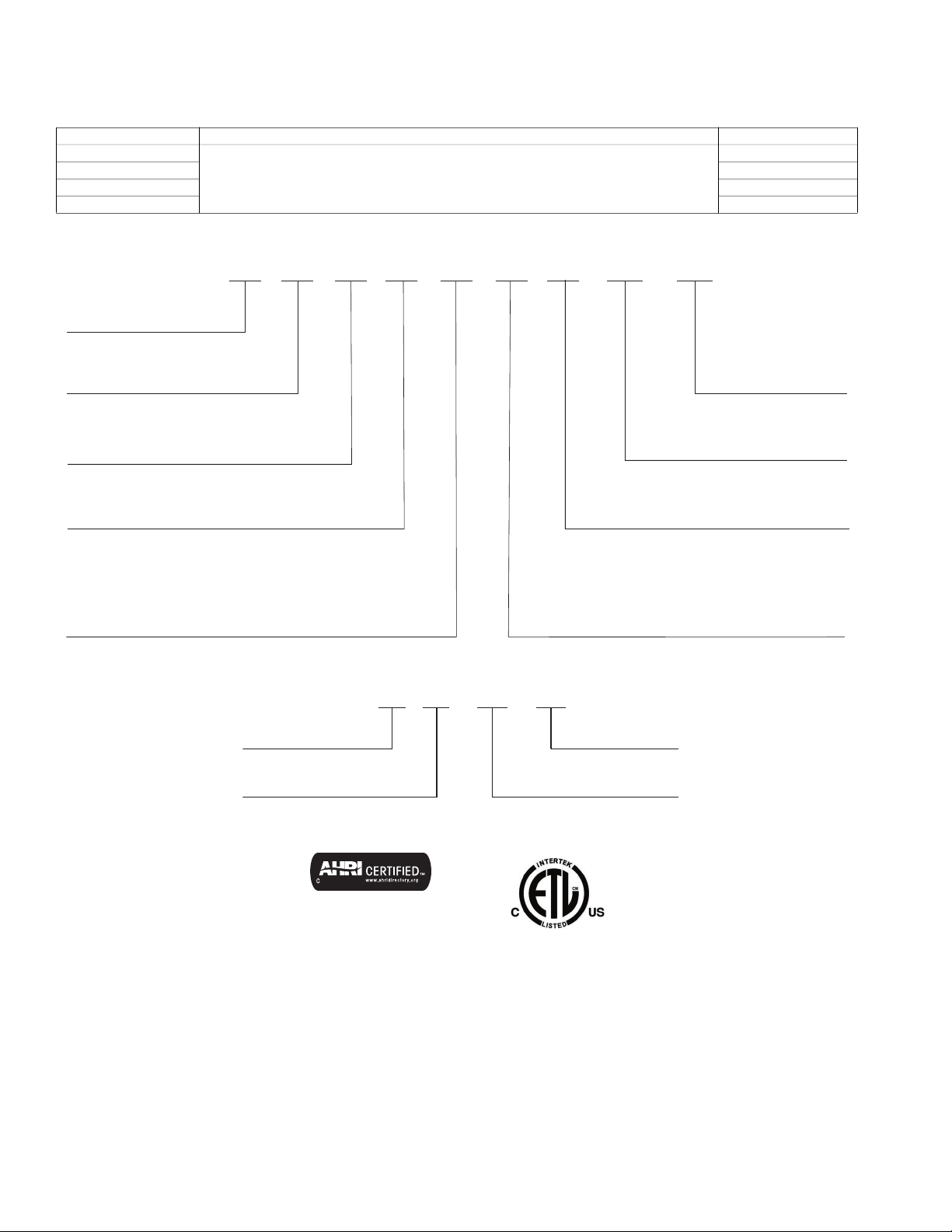
MODEL NUMBER NOMENCLATURE
619
P H A Q
09 X 3
619 = FAN COIL UNIT
P = MODEL
VOLTAGE
3 = 208/230-1-60
SYSTEM TYPE
H = HIGH WALL
MAJOR SERIES
X = NOT USED
NOMINAL CAPACITY
09 - 3/4 TON
12 - 1 TON
18 - 1.5 TONS
24 - 2 TONS
A
A = VARIATION
INDOOR FAN COIL TYPE
Q = HEAT PUMP
Week of Manufacture
Sequential Serial Number
V = ALL MODELSYear of Manufacture
Use of the AHRI Certified
TM Mark indicates a
manufacturer’s
participation in the
program For verification
of certification for individual
products, go to
www.ahridirectory.org.
Table 1 —Unit Sizes
SYSTEMS TONS VOLTAGE/PH/HZ INDOOR MODEL
9
12 619PHAQ12XA3
18 619PHAQ18XA3
208-230/1/60
24 619PHAQ24XA3
INDOOR UNIT
619PHAQ09XA3
2 Specifications subject to change without notice. SM619PHA-03
12
19 10001
V
Page 3
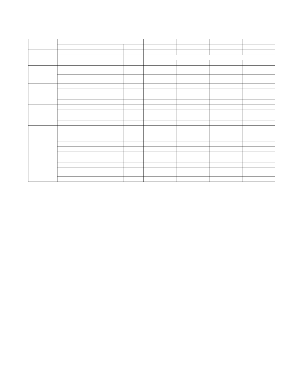
SPECIFICATIONS
SYSTEM
ELECTRICAL
CONTROLS
OPERATING
RANGE
PIPING
INDOOR COIL
INDOOR
Indoor Model
Voltage, Phase, Cycle V/Ph/Hz
Power Supply
MCA A.
Wireless Remote controller
(°F/°C Convertible)
Wired Remote controller
(°F/°C Convertible)
Cooling Indoor DB Min - Max °F (°C)
Heating Indoor DB Min - Max °F (°C)
Pipe Connection Size - Liquid in (mm)
Pipe Connection Size - Suction in (mm)
Face Area (sq. ft.) Sq. Ft.
No. Rows
Fins per inch
Circuits
Unit Width in (mm)
Unit Height in (mm)
Unit Depth in (mm)
Net Weight lbs (kg)
Number of Fan Speeds
Airflow (lowest to highest) CFM
Sound Pressure (lowest to highest) dB(A)
Air throw Data ft (m)
Moisture removal
Field Drain Pipe Size O.D. in (mm)
Table 2 — Specifications
SIZE 9 12 18 24
619PHAQ09XA3 619PHAQ12XA3 619PHAQ18XA3 619PHAQ24XA3
208/230-1-60 208/230-1-60 208/230-1-60 208/230-1-60
Indoor unit powered from outdoor unit
0.3 0.3 0.5 0.5
Standard Standard Standard Standard
Optional Optional Optional Optional
62~90 (17~32) 62~90 (17~32) 62~90 (17~32) 62~90 (17~32)
32~86 (0~30) 32~86 (0~30) 32~86 (0~30) 32~86 (0~30)
1/4 (6.35) 1/4 (6.35) 3/8” (9.52) 3/8” (9.52)
3/8 (9.52) 1/2 (12.7) 5/8” (15.9) 5/8” (15.9)
2.2 2.2 3.9 3.9
4 4 3 3
21 21 21 21
5 5 7 7
35.2 (895) 35.2 (895) 49.57 (1259) 49.57 (1259)
11.7 (298) 11.7 (298) 14.25 (362) 14.25 (362)
9.8 (248) 9.8 (248) 11.10 (282) 11.10 (282)
37.48 (17) 37.48 (17) 43.4 (19.7) 43.4 (19.7)
4 4 4 4
144/245/295/345 168/252/306/357 261/389/528/926 359/470/583/926
29/35.5/41.5/45.6 29/35.5/41.5/46.8 35.1/40.8/46.1/55.9 36.1/43.3/46.4/56.5
21.98 (6.7) 22.97 (7) 28.80 (8.7) 31.66 (9.65)
Pint/h
(L/h)
2.11 (1.0) 2.53 (1.2) 3.8 (1.8) 5.0 (2.39)
1 (25.4) 1 (25.4) 1 (25.4) 1 (25.4)
*Performance may vary based on the compatible outdoor units. See respective pages for performance data.
SM619PHA-03 Specifications subject to change without notice. 3
Page 4
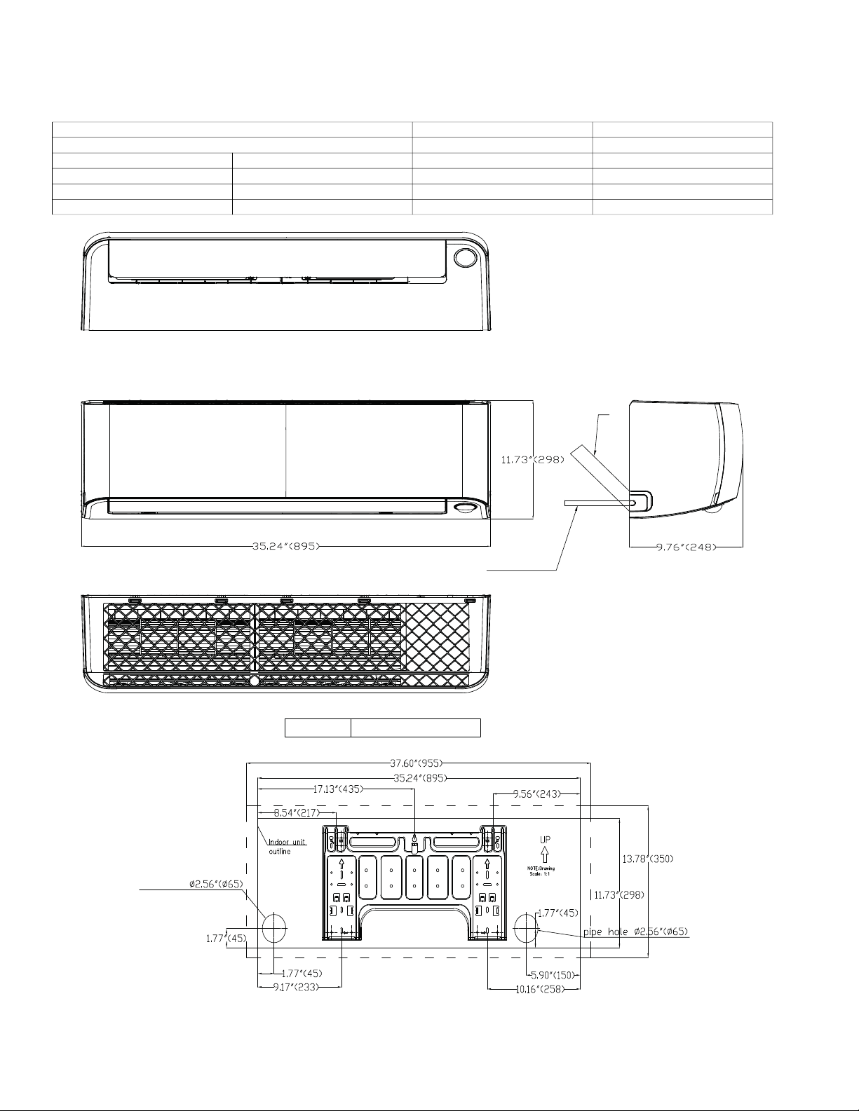
DIMENSIONS
Piping
Drain Hose
Drain Hose
Ø0.625"(16) L=25.20"(640)
Pipe hole
Units: Inch (mm)
Sizes 9K and 12K
Height In. (mm) 11.7 (298) 11.7 (298)
Width In. (mm) 35.2 (895) 35.2 (895)
Depth In. (mm) 9.8 (248) 9.8 (248)
Weight-Net Lbs (kg) 37.48 (17) 37.48 (17)
Table 3 — Dimension Sizes 09K and 12K
HIGH WALL UNIT SIZE 9K 12K
Voltage (208/230V) (208/230V)
Fig. 1 — Sizes 9K and 12K
NOTE: Drain adapter included with the indoor unit to allow the use of a 3/4 in. PVC Schedule 40 pipe where the actual
outside diameter is 1.05 in.
4 Specifications subject to change without notice. SM619PHA-03
Page 5
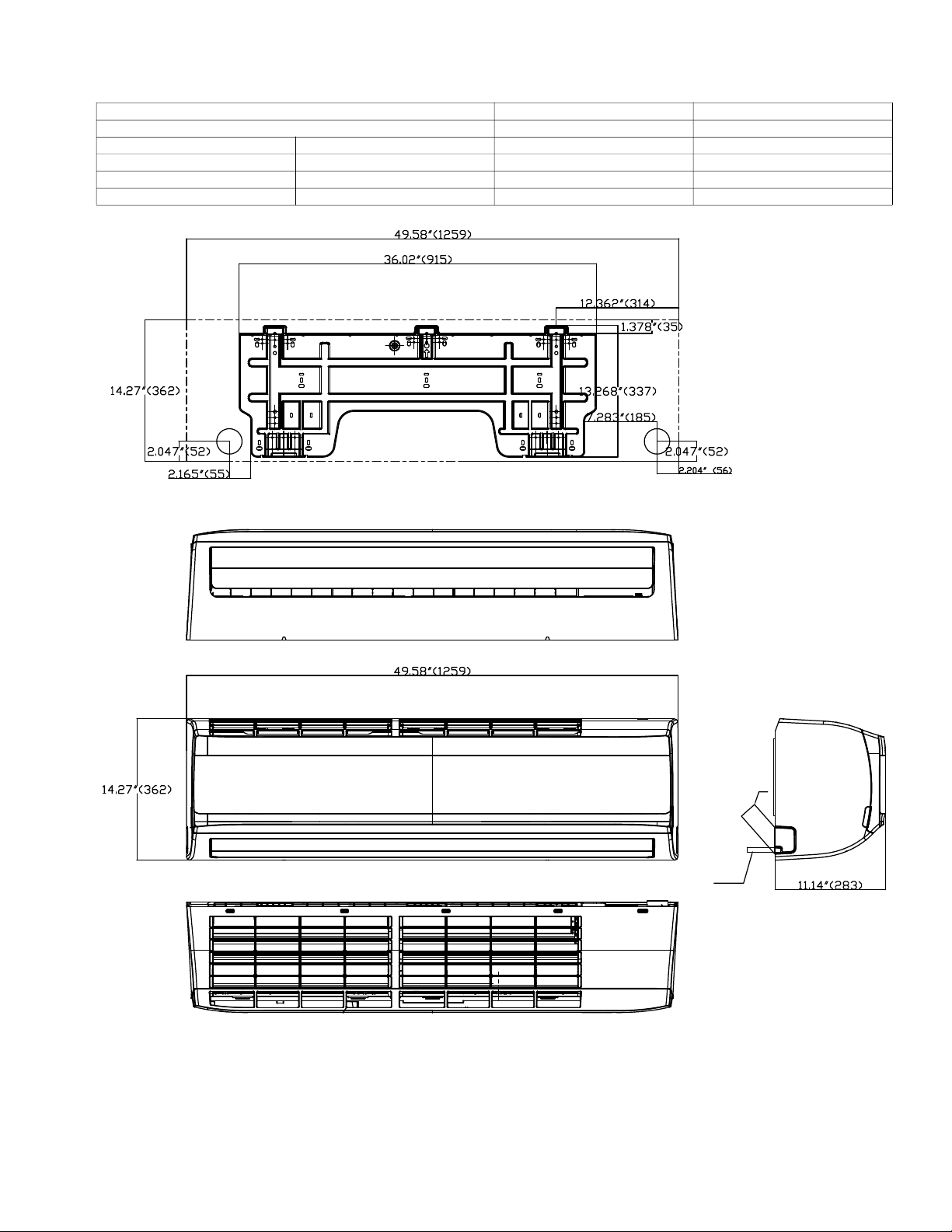
Sizes 18K and 24K
Piping
Drain Hose
HIGH WALL UNIT SIZE 18K 24K
Height In. (mm) 14.25 (362) 14.25 (362)
Width In. (mm) 49.57 (1259) 49.57 (1259)
Depth In. (mm) 11.10 (282) 11.10 (282)
Weight-Net Lbs (kg) 43.4 (19.7) 43.4 (19.7)
Table 4 — Dimension Sizes 18K and 24K
Voltage (208/230V) (208/230V)
Fig. 2 — Sizes 18K and 24K
SM619PHA-03 Specifications subject to change without notice. 5
Page 6
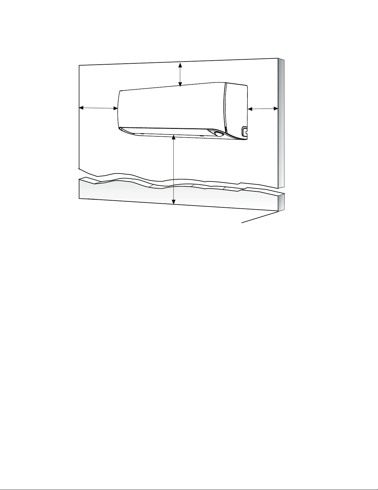
CLEARANCES
4.75 in
(12 cm)
min.
6 ft
(1.8m)
CEILING
FLOOR
5.9in. (15cm) min.
4.75 in
(12 cm)
min.
Fig. 3 — Indoor Unit Clearances
NOTE: The top clearance recommended for proper return airflow is 5.9 in (15cm). Reduction of this clearance may
decrease the performance of these units. This may be reduced to 3.2 in (80mm) as long as the right and left
clearances are achieved.
6 Specifications subject to change without notice. SM619PHA-03
Page 7
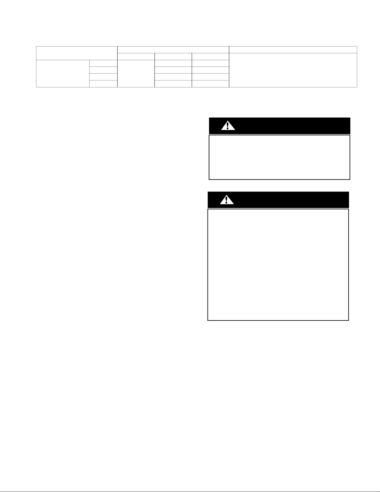
ELECTRICAL DATA
HIGH WALL UNIT SIZE
9K
Heat Pump Models
12K 0.34 0.027
18K 0.5 0.082
24K 0.5 0.082
WIRING
Table 5 — Electrical Data
INDOOR FAN MAX FUSE CB AMP
V-Ph-Hz FLA HP
0.34 0.027
208/230-1-60
Refer to outdoor unit installation instructions –
Indoor unit powered by the outdoor unit
All wires must be sized per NEC (National Electrical Code) or CEC
(Canadian Electrical Code) and local codes. Use the Electrical Data
table MCA (minimum circuit amps) and MOCP (maximum over
current protection) to correctly size the wires and the disconnect fuse
or breakers respectively.
Per the caution note, only stranded copper conductors with a 600 volt
insulation rating wire must be used.
Recommended Connection Method for Power and
Communication Wiring:
The main power is supplied to the outdoor unit. The field supplied
14/3 stranded wire with ground with a 600 volt insulation rating,
power/communication wiring from the outdoor unit to indoor unit
consists of four (4) wires and provides the power for the indoor unit.
Two wires are line voltage AC power, one is communication wiring
(S) and the other is a ground wire. Wiring between the indoor and
outdoor unit is polarity sensitive. The use of BX wire is NOT
recommended.
If installed in a high Electromagnetic field (EMF) area and
communication issues exists, a 14/2 stranded shielded wire can be
used to replace L2 and (S) between the outdoor unit and indoor unit
landing the shield onto ground in the outdoor unit only.
CAUTION
EQUIPMENT DAMAGE HAZARD
Failure to follow this caution may result in equipment damage
or improper operation.
Wires should be sized based on NEC and local codes.
CAUTION
EQUIPMENT DAMAGE HAZARD
Failure to follow this caution may result in equipment damage
or improper operation.
Be sure to comply with local codes while running wire from
the indoor unit to the outdoor unit.
Every wire must be connected firmly. Loose wiring may
cause the terminal to overheat or result in unit malfunction. A
fire hazard may also exist. Ensure all wiring is tightly
connected.
No wire should touch the refrigerant tubing, compressor or
any moving parts.
Disconnecting means must be provided and shall be located
within sight and readily accessible from the air conditioner.
Connecting cable with conduit shall be routed through the
hole in the conduit panel.
SM619PHA-03 Specifications subject to change without notice. 7
Page 8
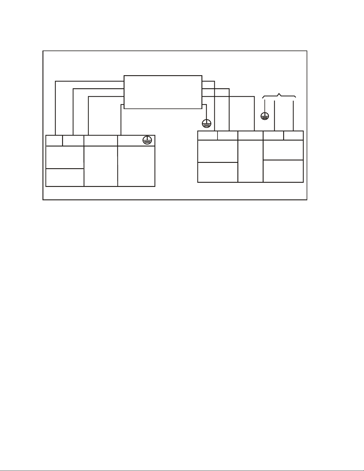
CONNECTION DIAGRAM
S
L1 L2
208/230-1-60
Main
Power Supply
L1
L2
S
L1
L2
CONNECTING CABLE
OUTDOOR TO INDOOR
Indoor Unit
Power Supply
208/230-1-60
Indoor
Signal
High
Voltage
GND
Ground
Power to
Indoor Unit
Indoor
Signal
High
Voltage
208/230-1-60
FIELD POWER SUPPLY
GND
208/230-1-60
208-230V Indoor Unit 208-230V Outdoor Unit
NOTES:
1. Do not use thermostat wire for any connection between the indoor and outdoor units.
2. All connections between the indoor and outdoor units must be as shown in Figure 4. The connections are polarity sensitive and improper wiring
will result in a fault code.
Fig. 4 — 208-230V
8 Specifications subject to change without notice. SM619PHA-03
Page 9
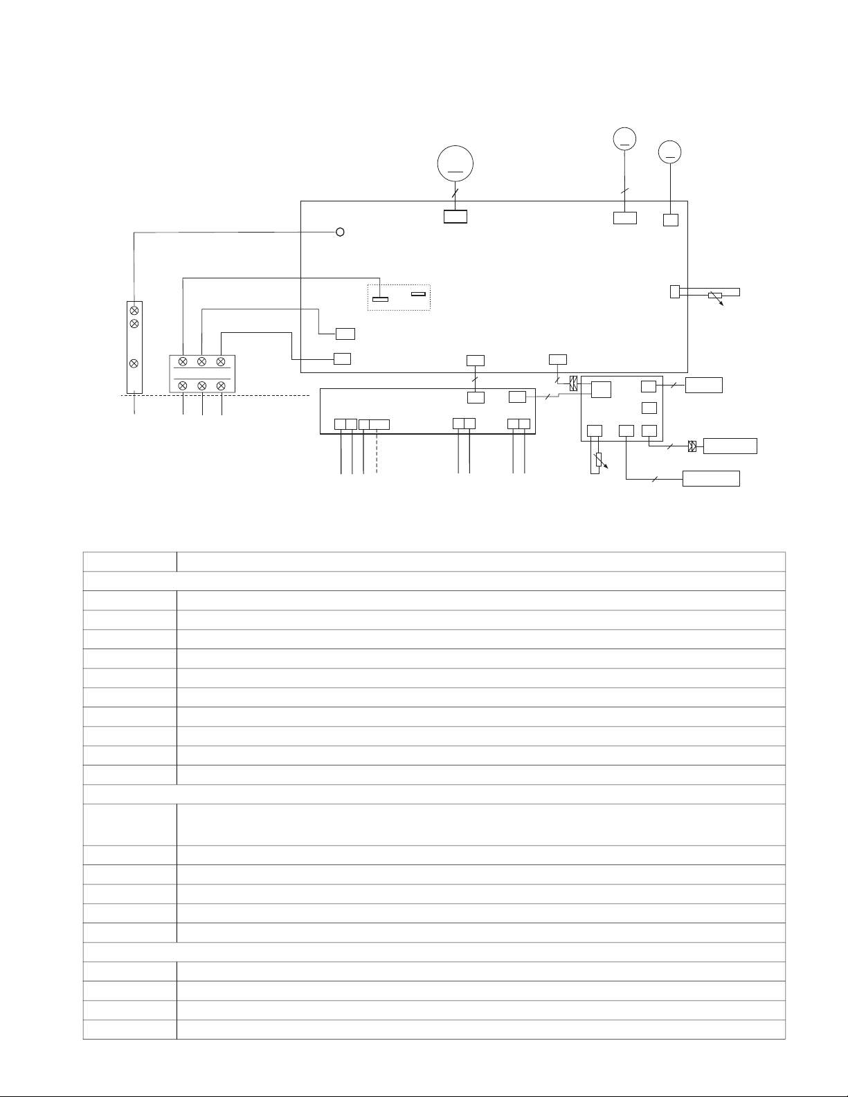
WIRING DIAGRAM
PIPE TEMPERATURE SENSOR
5
YELLOW
RED
M
CN20
SWING MOTOR2
INDOOR
FAN
M
5
CN3
N-IN
CN5
CN6
RY1
L-OUT
L-IN
BLUE(BLACK)
DISPLAY BOARD
CN10
MULTI-FUNCTION CONTROL BOARD
CN3
MAIN BOARD
CN2
CN4
CN1
CN40
CN43
CN32
2
CN42
CN41
CN45
CN46
X Y
E
12V/5V
To 485 Wire-controller
To Remote Switch
To Remote Alarm
4
3
- - - element is optional, the actual
shape shall prevail.
This symbol indicates the
INDOOR UNIT
OUTDOOR UNIT
L2
S
ROOM TEMPERATURE SENSOR
SWING MOTOR3
M
CN8
L1
CN5
CN6
Motion Sensor
5
Humidity Sensor
5
4
Wi-Fi
Earth Ground
CN1 & CN1A
+12V &
GND
Display
Vertical Horizontal
S
DC - Fan
P1_1
Indoor Wiring Diagram
Sizes 09K to 12K
CODE PART NAME
CN 10 Display board port DC 12V
CN 6 Output DC 5V pipe sensor
CN 8 Output DC12V,Swing motor
CN 20 Output DC12V,Swing motor
CN 3 Output DC 310V,fan motor
P1_1 Earth Ground
L-IN Power Voltage: AC 208-230V
N-IN Power Voltage: AC 208-230V
CN 5 Output: DC 0-24V Communication port to outdoor
CN 32 Output: DC 12V function board
CN1
CN 3 Output: DC 5V WI-FI controller (optional)
CN 2 Output: DC 5V Wire controller (optional)
CN 6 Output: DC 3.3V Infrared sensor (optional)
CN 5 Output: DC 5V Humidity sensor
CN 4 Output: DC5V Room temperature sensor (optional)
CN42 & CN41 Output: DC 5V To CCM Comm.Bus or 485 Wire-controller
CN 40 Input: DC 5V Connect to display board
CN 43 Input: DC 12V Connect to main board
CN 46 Output: DC 5V To Remote Switch
SM619PHA-03 Specifications subject to change without notice. 9
Input: DC 12V
4 wires connect to main board
3 wires connect to multi-function control board
Fig. 5 — Wiring Diagram - Sizes 09K and 12K
MAIN BOARD
DISPLAY BOARD
MULTI-FUNCTION CONTROL BOARD
Page 10
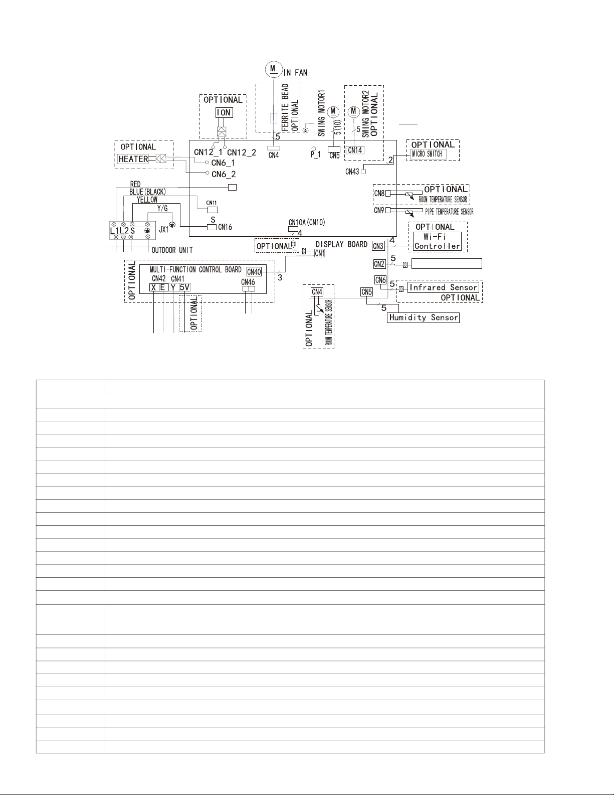
Sizes 18K to 24K
N
CN11
L-IN
CN 2
INDOOR UNIT
To Remote Switch
To CCM Comm.Bus or
OPTIONAL
Wire Controller
485 Wire-controller
Fig. 6 — Wiring Diagram - Sizes 18K and 24K
CODE PART NAME
MAIN BOARD
S (Cn16) Output:0-24VDC Communication port to outdoor
N(CN11) I nput:230VAC High Voltage N line from outdoor
L-IN (CN2) Input:230VAC High Voltage L line from outdoor
CN 6 Output:230VAC High Voltage Heater port (optional)
CN 12 Output:230V High Voltage Ion port (optional)
CN 4 Output:310VDC High Voltage Indoor DC fan
P_1 Output:0V Ground line welding on PCB
CN 5 Output:12VDC Swing motor 1
CN 14 Output:12VDC Swing motor2 (optional)
CN 43 Output:0-5VDC Micro switch (optional)
CN 44 Output:12VDC Plasma port (optional)
CN 8 Output:12VDC Room temperature sensor (optional)
CN 9 Output:12VDC Pipe temperature sensor
CN10A(CN10) Output:5VDC Connect to display board
DISPLAY BOARD
CN 1
CN 3 Output:5VDC Wi-Fi controller (optional)
CN 2 Output:5VDC Wire controller (optional)
CN 6 Output:3.3VDC Infrared sensor (operational)
CN 5 Output:5VDC Humidity sensor
CN 4 Output:12VDC Room temperature sensor (optional)
CN42&CN41 Output:5VDC To CCM Comm. Bus or 485 Wire-controller
CN40 Input:5VDC Connect to display board
CN 46 Output:5VDC To Remote Switch
10 Specifications subject to change without notice. SM619PHA-03
Input:5VDC
4 wires connect to main board
3 wires connect to multi-function control board
MULTI-FUNCTION CONTROL BOARD
Page 11
FAN AND MOTOR SPECIFICATIONS
LIQUID SIDE
GAS SIDE
HEAT
EXCHANGE
(EVAPORATOR)
HEAT
EXCHANGE
(CONDENSER)
COMPRESSOR
ïWAY VALV E
ïWAY VALV E
ïWAY VALV E
COOLING
HEATING
T2 Evaporator
temp. sensor
T1 Room temp.
sensor
ACCUMULATOR
CHECK VALVE
(Heating Model only)
CAPILLARY TUBE
Table 6 — Fan and Motor Specifications
HIGH WALL UNIT SIZE 9K 12K 18K 24K
(208/230V) (208/230V) (208/230V) (208/230V)
Material glass fiber+AS glass fiber+AS glass fiber+AS glass fiber+AS
HIGH WALL FAN
HIGH WALL
FAN MOTOR
Type GL-108*670-IN GL-108*670-IN GL-118*955-I GL-118*955-I
Diameter In (mm) 4.25 (108) 4.25 (108) 4.65(118) 4.65(118)
Height In (mm) 26.38 (670) 26.38 (670) 37.6(955) 37.6(955)
Model ZKFP-20-8-6-7 ZKFP-20-8-6-7 ZKFP-58-8-1-5 ZKFP-58-8-1-5
Volts V 208/230 208/230 208/230 208/230
Phase 1 1 1 1
Hertz 60 60 60 60
FLA 0.034 0.034 0.5 0.5
Type DC DC DC DC
Insulation class E E E E
Safe class IPX0 IPX0 IP40 IP40
Input W 50 50 58 58
Output W 20 20 60 60
Range of current Amps 0.023 0.023 0.1~0.48 0.1~0.48
Rated current Amps 0.023±10% 0.023±10% 0.65 0.65
Capacitor µF No Capacitor
Rated HP HP 0.027 0.027 0.082 0.082
Speed rev/min 1000/850/650 1050/900/650 1700/1660/1350 1700/1660/1350
Rated RPM rev/min 1000 1050 1700 1700
Max. input W 70 70 125 125
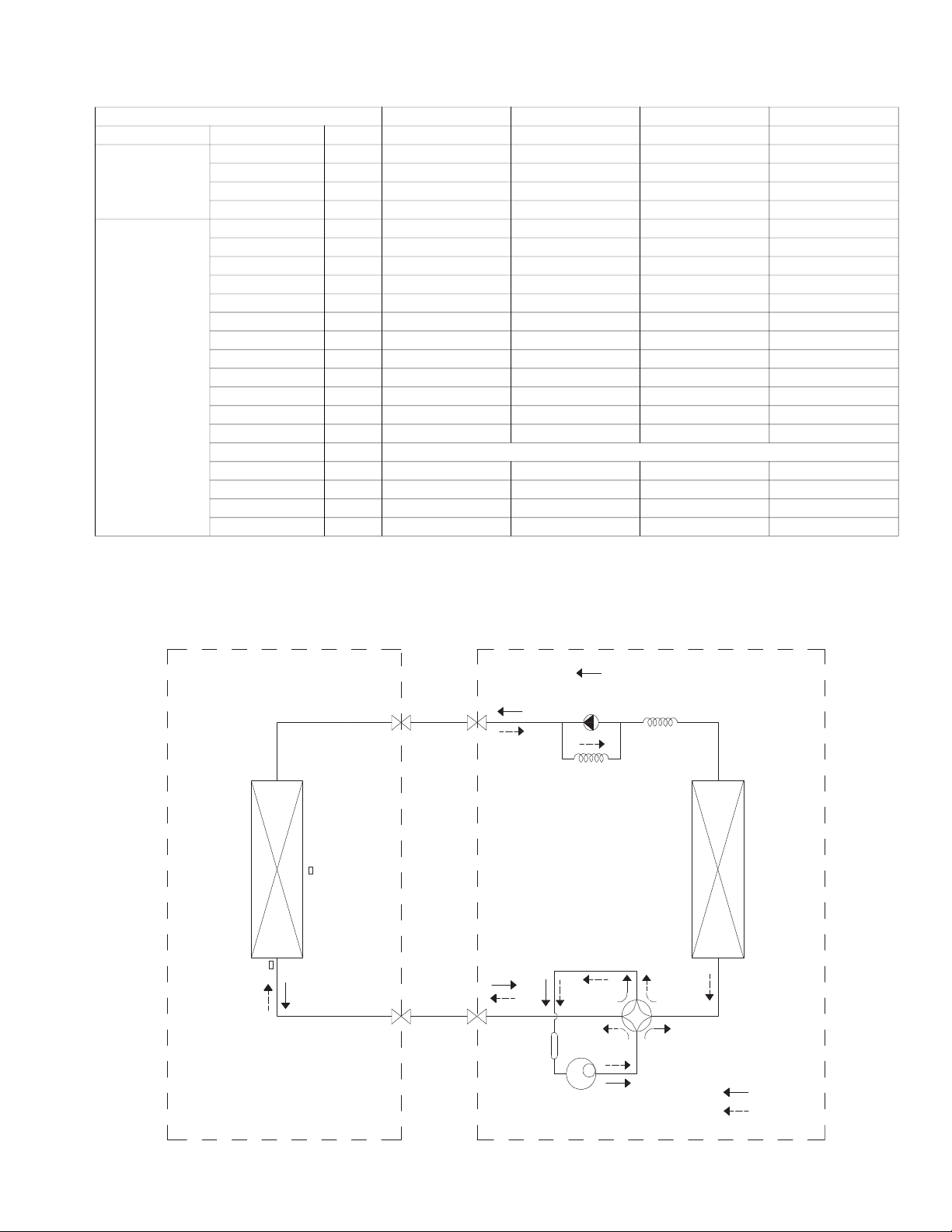
REFRIGERATION CYCLE DIAGRAM
ROODTUOROODNI
SM619PHA-03 Specifications subject to change without notice. 11
Fig. 7 — Heat Pumps
Page 12
REFRIGERANT LINES
utdoor Unit
t
Gas Side
Liquid Side
A
B
C
D
Manifold Gage
500 microns
Lo
w pressure valve
High side valve
Low pressure hose
Charge hose
Vacuum
pump
Gas side valve
500
MINUTES
01234567
1000
1500
LEAK IN
SYSTEM
VACUUM
TIGHT
TOO WET
TIGHT
DRY SYSTEM
2000
MICRONS
2500
3000
3500
4000
4500
5000
CHECK FOR TIGHT, DRY SYSTEM
(IF IT HOLDS DEEP VACUUM)
EVACUATE TO 1500 MICRONS
EVACUATE TO 500 MICRONS MINIMUM (HOLD FOR 30 MINUTES)
RELEASE
CHARGE INTO SYSTEM BY OPENING
VALVES COMPLETELY
BREAK VACUUM WITH DRY NITROGEN TO 2 PSIG
EVACUATE TO 1000 MICRONS
BREAK VACUUM WITH DRY NITROGEN TO 2 PSIG
IMPORTANT: Both refrigerant lines must be insulated separately.
Table 2 on page 3 lists the pipe sizes for the indoor unit. Refer to the outdoor unit installation instructions for other allowed piping lengths and
refrigerant information.
SYSTEM EVACUATION AND CHARGING
CAUTION
UNIT DAMAGE HAZARD
Failure to follow this caution may result in equipment damage
or improper operation.
Never use the system compressor as a vacuum pump.
Refrigerant tubes and indoor coil should be evacuated using the
recommended deep vacuum method of 500 microns. The alternate
triple evacuation method may be used if the following procedure is
followed. Always break a vacuum with dry nitrogen.
System Vacuum and Charge
Using Vacuum Pump
1. Completely tighten flare nuts on the line set at both the indoor and
outdoor units. DO NOT open the service valves on the outdoor unit
for the new installation or the replacement unit. Open the service
valves on the outdoor unit if repairs have been made to the
refrigerant sealed system. Connect the manifold gauge low pressure
hose to the charge port of the gas side service valve (see Fig. 8).
2. Connect the charge hose to the vacuum pump.
3. Fully open the low pressure valve of manifold gage (see Fig. 9).
4. Start the vacuum pump.
5. Evacuate using deep vacuum or triple evacuation method.
6. After evacuation is complete, fully close the pressure valve side of
manifold gage and stop the vacuum pump operation.
7. The factory charge contained in the outdoor unit is good for up to
25ft. (8 m) of line length. If vacuum is complete per Fig. 10 or 11,
open service valves to release factory charge into the system.
8. Disconnect the charge hose from the charge connection of the gas
side service valve.
9. Securely tighten the service valve caps.
O
Refrigerant
Indoor Uni
Deep Vacuum Method
The deep vacuum method requires a vacuum pump capable of pulling
a vacuum of 500 microns and a vacuum gage capable of accurately
measuring this vacuum depth. The deep vacuum method is the most
positive way of assuring a system is free of air and liquid water (see
Fig. 10).
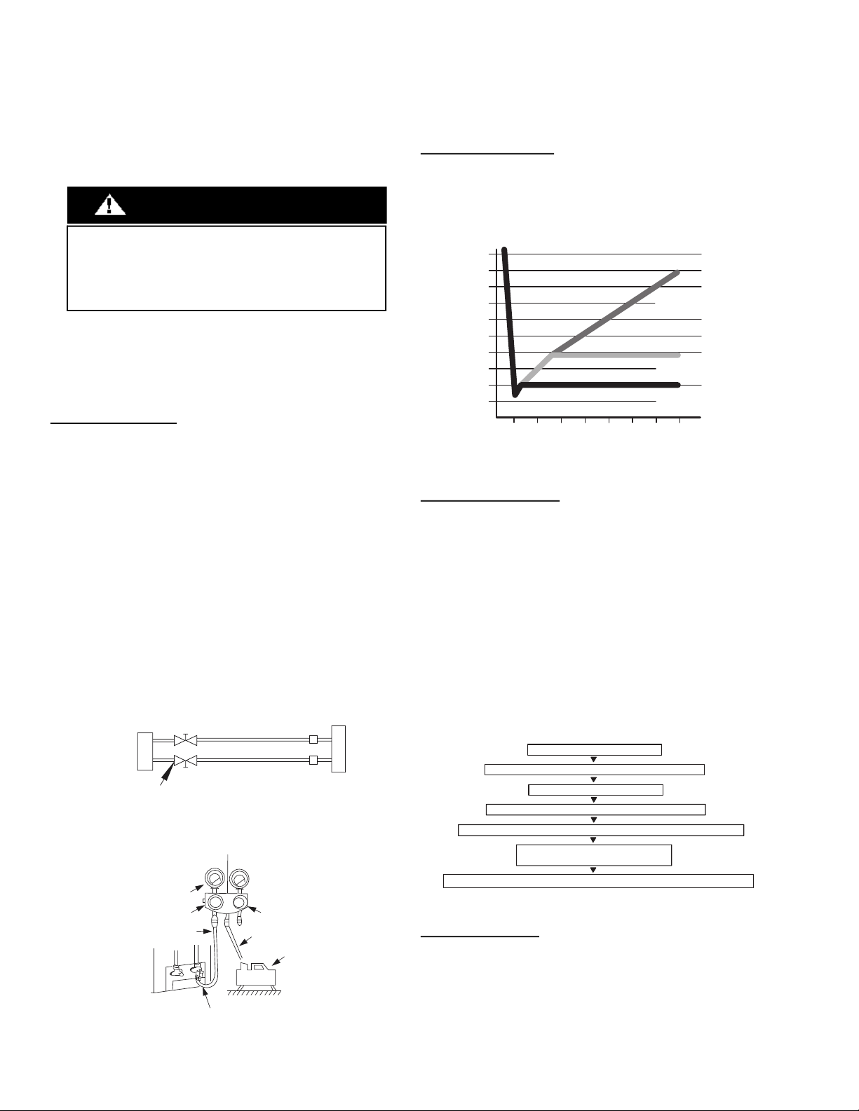
Fig. 10 — Deep Vacuum Graph
Triple Vacuum Method
The triple evacuation method should be used. Refer to Fig. 9 and
proceed as follows:
1. Pump the system down to 1500 microns and allow the pump to
continue operating for an additional 15 minutes.
2. Close the service valves and shut off the vacuum pump.
3. Connect a dry nitrogen cylinder and regulator to the system and
break vacuum until the system reaches 2 psig.
4. Close the service valve and allow the system to stand for 1hr.
During this time, the dry nitrogen can diffuse throughout the system
absorbing moisture.
5. Pump the system down to 1000 microns.
6. Break the vacuum with dry nitrogen (2 psig).
7. Pump the system down to 500 microns.
8. Perform the hold test for 30 minutes.
Service Valve
Fig. 8 — Service Valve
12 Specifications subject to change without notice. SM619PHA-03
Fig. 9 — Manifold
Fig. 11 — Triple Evacuation Method
Final Tubing Check
IMPORTANT: Check to be certain factory tubing on both
indoor and outdoor unit has not shifted during shipment.
Ensure tubes are not rubbing against each other or any
sheet metal. Pay close attention to feeder tubes, making
sure wire ties on feeder tubes are secure and tight.
Page 13
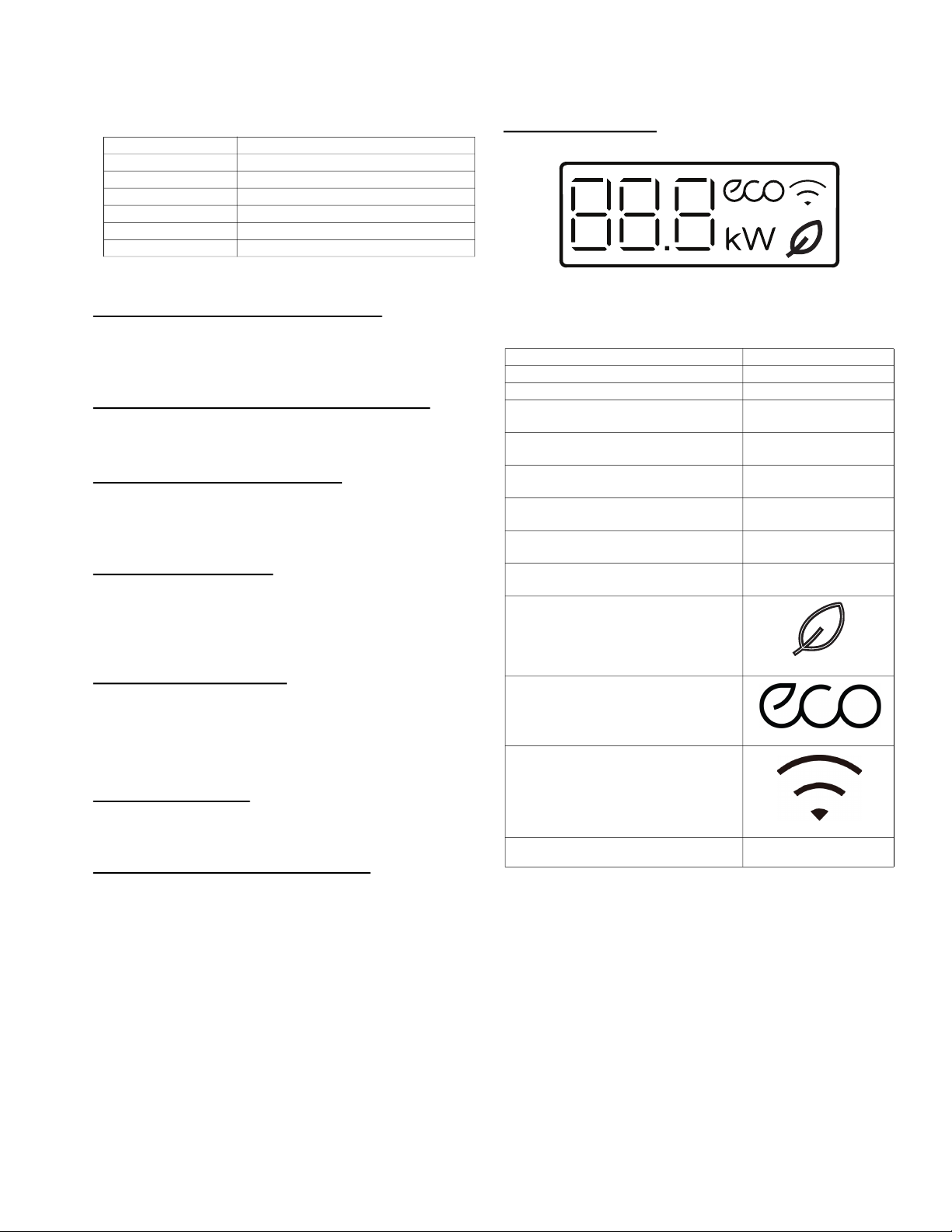
OPERATION MODES AND FUNCTIONS
Abbreviation
Table 7 — Unit Element Abbreviations
ABBREVIATION ELEMENT
T1 Indoor room temperature
T2 Evaporator Coil temperature
T3 Condenser Coil temperature
T4 Outdoor ambient temperature
Tsc Adjusted setting temperature
TP Compressor discharge temperature
Safety Features
Compressor Three-Minute Delay at Restart
Compressor functions are delayed for up to ten seconds upon the
first start-up of the unit, and are delayed for up to three minutes
upon subsequent unit restarts.
Automatic shutoff based on discharge temperature
If the compressor discharge temperature exceeds 226F (108C)
for nine seconds, the compressor ceases operation.
Automatic shutoff based on fan speed
If the indoor fan speed registers below 300RPM or over 1500RPM
for an extended period of time, the unit ceases operation and the
corresponding error code is displayed on the indoor unit.
Inverter module protection
The inverter module has an automatic shutoff mechanism based on
the unit’s current, voltage, and temperature. If automatic shutoff is
initiated, the corresponding error code is displayed on the indoor
unit and the unit ceases operation.
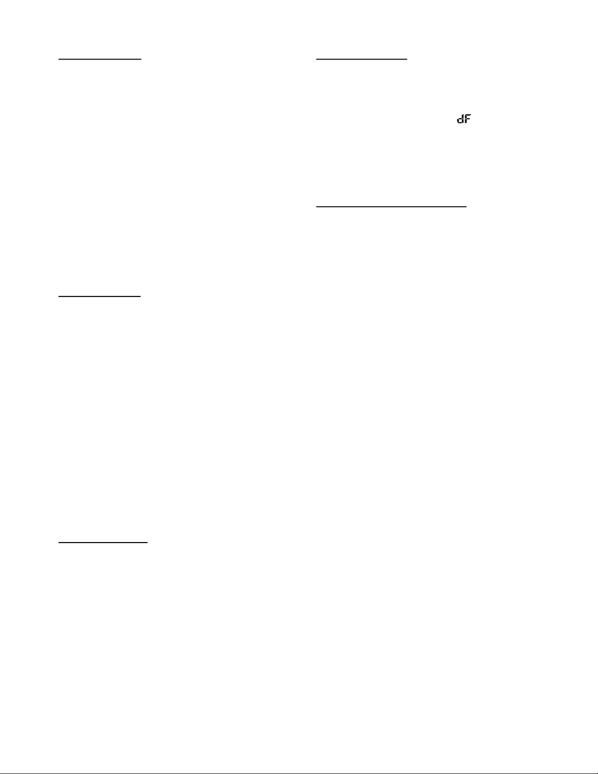
Display Function
Unit Display Functions
Fig. 12 — Unit Display Functions
Table 8 — Unit Function Displays
FUNCTION DISPLAY
Temperature Set temperature value
Temperature (FAN and DRYING mode) Room temperature
Activation of Timer ON, Fresh, Swing,
Turbo, or Silent
Cancellation of Timer OFF, Fresh, Swing,
Turbo, or Silent
Defrost
Warming in heating mode
Self-clean
Heating in room temperature under
46°F (8°C) or 54°F (12°C)
Fresh (Not available on these systems)
ON(3S)
OF(3S)
dF
cF
SC
FP
Indoor fan delayed operation
• When the unit starts, the louver is automatically activated and the
indoor fan will operate after a period of setting time or when the
louver is in place.
• If the unit is in HEATING mode, the indoor fan is regulated by the
anti-cold wind function.
Compressor Preheating
Preheating is automatically activated when the T4 sensor is lower than
setting temperature.
Sensor redundancy and automatic shutoff
• If one temperature sensor malfunctions, the air conditioner
continues operation and displays the corresponding error code,
allowing for emergency use.
• When more than one temperature sensor malfunctions, the air
conditioner ceases operation.
ECO function
Wi-Fi Control
The current operation power
(Not available on these systems)
kW
SM619PHA-03 Specifications subject to change without notice. 13
Page 14

FAN Mode
When the FAN mode is activated:
• The outdoor fan and compressor stop.
• Temperature control is disabled and the indoor room temperature
is displayed.
• The indoor fan speed can be set to 1%~100%, or AUTO.
• The louver operations are identical to those in COOLING mode.
• Auto fan: In FAN-ONLY mode, the AC operates the same as auto
fan in the COOLING mode with the temperature set at 75F
(24°C). (Tsc=75°F (24°C)).
COOLING Mode
Compressor control
Reach the configured temperature:
1. When the compressor runs continuously for less than 120 minutes.
• If the following conditions are satisfied, the compressor ceases
operation.
• While the calculated frequency (fb) is less than the minimum
limit frequency (FminC).
• While protective time is more than or equal to ten minutes.
• While T1 is lower than or equal to (Tsc-CDIFTEMP -1°F (-0.5°C)
NOTE: CDIFTEMP is the EEPROM setting parameter. It
is 4
°F (2°C).
2. When the compressor runs continuously for more than 120
minutes.
• If the following conditions are satisfied, the compressor ceases
operation.
• When calculated frequency (fb) is less than minimum limit
frequency (FminC).
• When protective time is more than or equal to ten minutes.
• When T1 is lower than or equal to (Tsc-CDIFTEMP).
NOTE: CDIFTEMP is the EEPROM setting parameter. It
is 4
°F (2°C).
3. If one of the following conditions is satisfied, regardless of time.
• Compressor running frequency is more than the test frequency.
• When the compressor running frequency is equal to the test
frequency, T4 is more than 59°F (15°C) or no T4 or T4 fault.
• Change setting temperature
• Turbo or sleep function on/off
• Various frequency limit shutdown occurs
Indoor Fan Control
1. In the COOLING mode, the indoor fan operates continuously. The
fan speed can be set to 1%-100%, or AUTO.
2. AUTO fan
• Descent Curve
• When T1-Tsc is lower than or equal to 6F (3.5C), fan speed
reduces to 80%;
• When T1-Tsc is lower than or equal to 2F (1C), fan speed
reduces to 60%;
• When T1-Tsc is lower than or equal to 1F (0.5C), fan speed
reduces to 40%;
• When T1-Tsc is lower than or equal to 0F (0C), fan speed
reduces to 20%;
• When T1-Tsc is lower than or equal to -1F (-0.5C), fan
speed reduces to 1%.
• Rise Curve
• When T1-Tsc is higher than 0F (0C), fan speed increases to
20%;
• When T1-Tsc is higher than 1F (0.5C), fan speed increases
to 40%;
• When T1-Tsc is higher than 2F (1C), fan speed increases to
60%;
• When T1-Tsc is higher than 3F (1.5C), fan speed increases
to 80%;
• When T1-Tsc is higher than 7F (4C), fan speed increases to
100%.
Outdoor Fan Control
• The outdoor unit runs at a different fan speed according to T4 and
the compressor running frequency.
• For different outdoor units, the fan speeds are different.
Condenser Temperature Protection
When the condenser temperature exceeds a configured value, the
compressor ceases operations.
Evaporator Temperature Protection
When the evaporator temperature drops below a configured value, the
compressor and outdoor fan ceases operations.
NOTE: CDIFTEMP is EEPROM setting parameter. It is
4
°F (2°C).
14 Specifications subject to change without notice. SM619PHA-03
Page 15
HEATING Mode
“ ”
Compressor control
1. Reach the configured temperature:
• If the following conditions are satisfied, the compressor ceases
operation.
• While the calculated frequency (fb) is less than the minimum
limit frequency (FminC).
• When the protective time is more than or equal to ten minutes.
• When T1 is higher than or equal to Tsc+HDIFTEMP2.
NOTE: HDIFTEMP2 is the EEPROM setting parameter.
It is 4
°F (2°C).
• If one of the following conditions is satisfied, regardless of
time.
• Compressor running frequency is more than test frequency.
• When the compressor running frequency is equal to the test
frequency, T4 is more than 59°F (15°C) or no T4 or T4 fault.
• Change the setting temperature.
• TURBO or SLEEP function on or off.
2. When the current is higher than the predefined safe value, the surge
protection is activated, causing the compressor to cease
operations.
Indoor Fan Control
1. In the HEATING mode, the indoor fan operates continuously. The
fan speed can be set to 1%-100%, or muted.
2. AUTO fan
• Rise curve
• When T1-Tsc is higher than -3°F (-1.5°C), fan speed reduces
to 80%;
• When T1-Tsc is higher than 0°F (0°C), fan speed reduces to
60%;
• When T1-Tsc is higher than 1°F (0.5°C), fan speed reduces to
40%;
• When T1-Tsc is higher than 2°F (1°C), fan speed reduces to
20%.
•Descent curve
•When T1-Tsc is lower than or equal to 1°F (0.5°C), fan speed
increases to 20%;
• When T1-Tsc is lower than or equal to 0°F (0°C), fan speed
increases to 60%;
• When T1-Tsc is lower than or equal to -3°F (-1.5°C), fan
speed increases to 80%;
• When T1-Tsc is lower than or equal to -1.5°F (-3°C), fan
speed increases to 100%.
DEFROSTING Mode
• The unit enters defrosting mode according to changes in the
temperature value of T3, T4 as well as the compressor running
time.
• In the DEFROSTING mode, the compressor continues to run, the
indoor and outdoor motor will cease operation, the defrost light of
the indoor unit will turn on, and the symbol appears.
• If any one of the following conditions is satisfied, defrosting ends
and the machine switches to the normal HEATING mode:
• T3 rises above TCDE1C.
• T3 maintained above TCDE2C for 80 seconds.
• Unit runs for 15 minutes consecutively in the DEFROSTING
mode.
Evaporator Temperature Protection
• Off: Compressor stops.
• Decrease: Decrease the running frequency to the lower level per
20 seconds.
• Hold: Keep the current frequency.
• Resume: No limitation for frequency.
AUTO Mode
• This mode can be selected with the remote controller and the
setting temperature can be changed between 61°F~86°F
(16°C~30°C).
• In the AUTO mode, the machine selects the COOLING,
HEATING, AUTO-DRYING or FAN-ONLY mode on the basis
of T1,Ts, T4 and relative humidity.
• If the setting temperature is modified, the machine selects a new
running function.
DRY Mode
In the DRY mode, the air conditioner operates the same as auto fan in
the COOLING mode.
1. Mute function is active.
• All protections are activated and operate the same as they do
that in COOLING mode.
2. Low Room Temperature Protection
• If the room temperature is lower than 50°F (10°C), the
compressor ceases operations and does not resume until the
room temperature exceeds 54°F (12°C).
Outdoor Fan Control
•The outdoor unit runs at a different fan speed according to T4
and compressor running frequency.
• For different outdoor units, the fan speeds differ.
SM619PHA-03 Specifications subject to change without notice. 15
Page 16

Forced Operation Function
• Forced COOLING Mode
The compressor and outdoor fan continues to run and the indoor
fan runs at rated speed. After running for 30 minutes, the air
conditioner switches to AUTO mode with a preset temperature
of 75°F (24°C).
• Forced AUTO Mode:
Forced auto mode operates the same as normal AUTO mode
with a preset temperature of 75°F (24°C).
•The unit exits the forced operation when it receives the following
signals:
• Switch on
• Switch off
• Timer on
• Timer off
• Changes in:
• Mode
• Fan Speed
• Setting Temperature
Timer Function
• The Timing range is 24 hours.
• Timer on. The machine turns on automatically when reaching the
setting time.
• Timer off. The machine turns off automatically when reaching the
setting time.
• Timer on/off. The machine turns on automatically when reaching
the setting “on” time, and then turns off automatically when
reaching the setting “off” time.
• Timer off/on. The machine turns off automatically when reaching
the setting “off” time, and then turns on automatically when
reaching the setting “on” time.
• The timer function will not change the AC current operation mode.
Suppose the AC is off now, it will not start up first after setting the
“timer off” function. And when reaching the setting time, the timer
LED will be off and the AC running mode has not been changed.
• The setting time is relative time.
• The AC will quit the timer function when it has malfunction.
Auto-Restart Function
• The indoor unit has an auto-restart module that allows the unit to
restart automatically. The module automatically stores the current
settings and, in the case of a sudden power failure, will restore
those setting automatically within 3 minutes after power returns.
• If there is a power failure while the unit is running, the compressor
starts 3 minutes after the unit restarts. If the unit was already off
before the power failure, the unit stands by.
46°F (8°C) Heating
In the HEATING mode, the temperature can be set to as low as 46°F
(8°C), preventing the indoor area from freezing if unoccupied during
severe cold weather.
ECO Function
• Used to enter the energy efficient mode.
•Under the COOLING mode, press ECO, the remote controller
adjusts the temperature automatically to 75°F (24°C), AUTO fan
speed to save energy (however only if the set temperature is less
than 75°F (24°C). If the set temperature is more than 75°F
(24°C) and 86°F (30°C), press ECO, the fan speed will change to
AUTO, the set temperature will remain unchanged.
• When AC receives signals, such as switch off, Turbo operation,
Silence operation, Self Clean operation, Forced COOLING
operation, mode setting, SLEEPING mode, or adjusting the set
temperature to less than 75°F (24°C), it will exit the ECO
operation.
• Operation time in ECO mode is 8 hours. After 8 hours the air
conditioner exits this mode.
• If there is a malfunctioning temperature sensor in, the air
conditioner will exit ECO mode.
• The indoor fan runs at auto fan when it enters the ECO mode. The
setting temperature and setting fan speed can be changed with the
remote controller.
Self Clean
• Press “Self Clean” when the unit is in the COOLING or
DRYING mode, the indoor unit runs at the low fan speed for 16
minutes then turn off.
• Self Clean keeps the indoor unit dry and prevents mold growth.
SLEEP Function
• The SLEEP function is available in COOLING, HEATING, or
AUTO modes.
• The operational process for sleep mode is as follows:
•When cooling, the temperature rises 2°F (1°C) (to not higher
than 86°F (30°C) every hour. After 2 hours, the temperature
stops rising and the indoor fan is fixed at low speed.
•When heating, the temperature decreases 2°F (1°C) (to not
lower than 61°F (16°C)) every hour.
•After 2 hours, the temperature stops decreasing and the indoor
fan is fixed at low speed. Anti-cold wind function takes
priority.
• The operating time for the SLEEP mode is 8 hours, after which,
the unit exits this mode and turns off.
• The timer setting is available in this mode.
Follow Me
• If you press “Follow Me” on the remote controller, the indoor unit
will beep. This indicates the “Follow Me” function is active.
• Once active, the remote controller will send a signal every 3
minutes, with no beeps. The unit automatically sets the
temperature according to the measurements from the remote
controller.
• The unit will only change modes if the information from the
remote controller makes it necessary, not from the unit’s
temperature setting.
• If the unit does not receive a signal for 7 minutes or you press
“Follow Me”, the function turns off. The unit regulates
temperature based on its own sensor and settings.
16 Specifications subject to change without notice. SM619PHA-03
Page 17
Silence
Press SILENCE on the remote controller to enable the SILENCE
function. While this function is active, the indoor unit runs at faint
breeze (1% fan speed), which reduces noise to the lowest possible
level.
Occupancy Sensor (Sizes 09K-12K)
With the built-in infrared sensor, the indoor unit detects human
movement. The compressor operates in a low frequency if you leave
the room for 30 minutes. The compressor operates in a lower
frequency if you leave the room for 120 minutes, and resumes
automatically when you come back, which helps save energy.
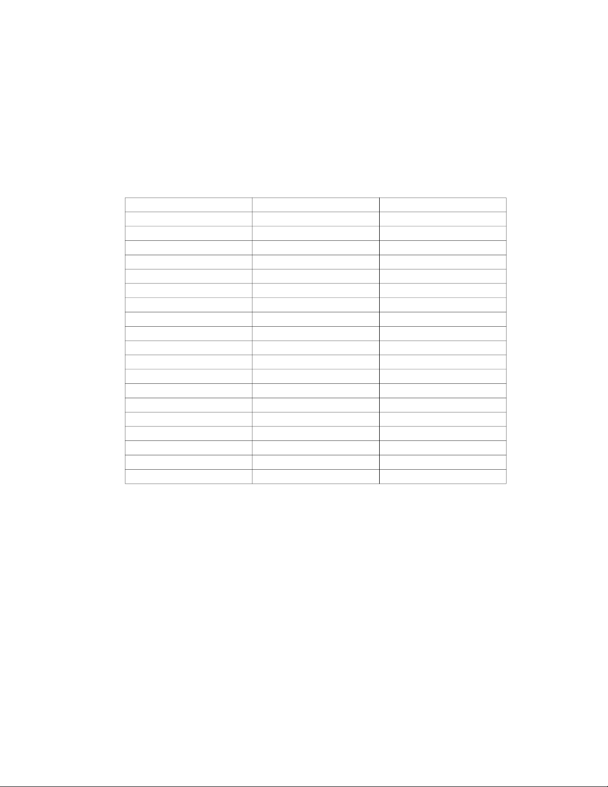
Table 9 — Information Codes
DISPLAYED CODE EXPLANATION ADDITIONAL NOTES
T1 T1 T1 temperature
T2 T2 T2 temperature
T3 T3 T3 temperature
T4 T4 T4 temperature
TP TP TP temperature
Targeted Frequency FT Targeted Frequency
Actual Frequency TR Actual Frequency
Compressor Current dL N/A
Outdoor AC Voltage UO N/A
Indoor capacity test Sn N/A
Reserve -- Running mode
Outdoor Fan Speed Pr Outdoor fan speed
EXV opening angle LR EXV opening angle
Indoor fan speed IR Indoor fan speed
Indoor humidity HU N/A
Adjusted setting temperature TT N/A
Indoor dust concentrations DT N/A
WIFI signal strength IF N/A
GA algorithm frequency OT N/A
Information Inquiry
To enter information inquiry status, complete the following procedure
within ten seconds:
• Press LED 3 times.
• Press SWING 3 times. If successful, you will hear beeps for two
seconds.
• Use LED and SWING to cycle through the information displayed.
• Press LED to display the next code in the sequence.
• Press SWING to display the previous code.
Table 9 displays the information codes. The screen displays the code
for two seconds, then the information for 25 seconds.
SM619PHA-03 Specifications subject to change without notice. 17
Page 18
TROUBLESHOOTING
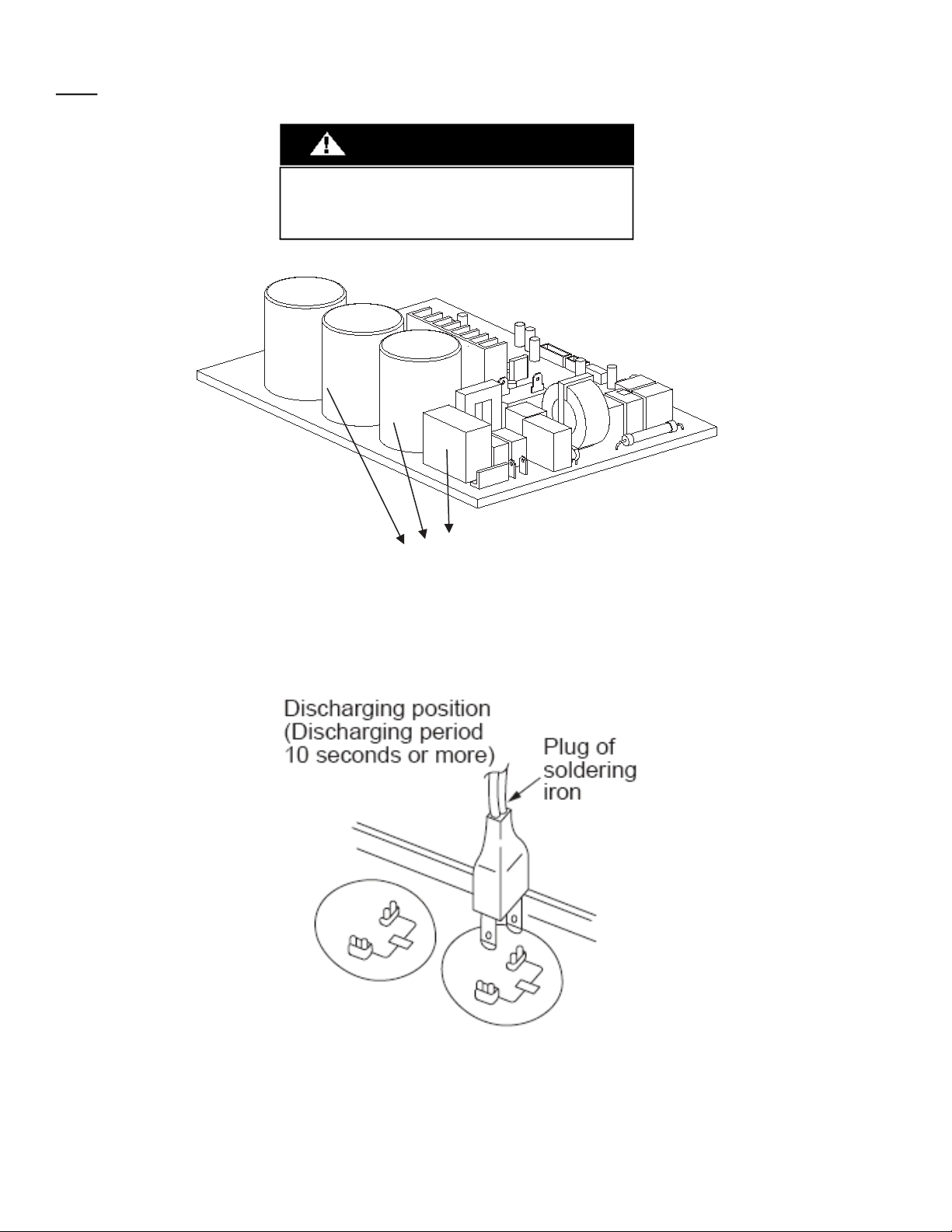
Electrolytic Capacitors
Safety
WARNING
UNIT DAMAGE HAZARD
Electricity remains in capacitors even when the power supply is off.
Ensure the capacitors are fully discharged before troubleshooting.
(HIGH VOLTAGE! CAUTION!)
Fig. 13 — Electrolytic Capacitors
For other models, please connect discharge resistance (approximately 100Ù 40W) or a soldering iron (plug) between the +, - terminals of the
electrolytic capacitor on the other side of the outdoor PCB.
Fig. 14 — Discharge Position
NOTE: Fig. 14 is for reference only. Actual appearances may vary.
18 Specifications subject to change without notice. SM619PHA-03
Page 19
TROUBLESHOOTING (continued)
Error Display (Indoor Unit)
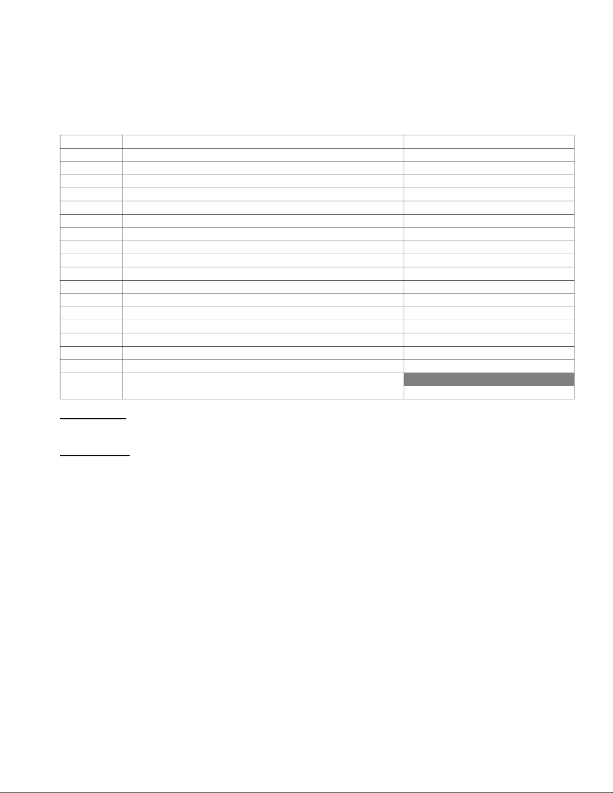
When the indoor unit encounters a recognized error, the indicator light flashes in a corresponding series, the timer display may turn on or
begin flashing, and an error code displays. These error codes are described in Table 10.
Table 10 — Error Codes
DISPLAY ERROR INFORMATION SOLUTION
E0/EA Indoor unit EEPROM parameter error Page 27
E1 Indoor / outdoor units communication error Pages 28 - 29
E2 Zero crossing detection error diagnosis and solution Page 30
E3 The indoor fan speed is operating outside of the normal range Page 31
E4 Indoor room temperature sensor T1 is in open circuit or has short circuited Page 37
E5 Evaporator coil temperature sensor T2 is in open circuit or has short circuited Page 37
EB Communication error between the indoor PCB and display board Page 38
EF Occupancy Sensor module error Page 33
F0 Overload current protection Page 39
F1 Outdoor ambient temperature sensor T4 open circuit or short circuit Page 37
F2 Condenser coil temperature sensor T3 is in open circuit or has short circuited Page 37
F3 Compressor discharge temperature sensor TP open circuit or short circuit Page 37
F4 Outdoor unit EEPROM parameter error Page 27
F5 The outdoor fan speed is operating outside of the normal range Page 31
P0 IPM malfunction or IGBT over-strong current protection Page 40
P1 Over voltage or over low voltage protection Page 34
P2 High temperature protection of IPM module Page 35
P3 Outdoor ambient temperature is too low
P4 Inverter compressor drive error Page 36
For other codes
The display board may show a garbled code or a code undefined by the service manual. Ensure that this code is not a temperature reading.
Troubleshooting
Test the indoor unit using the remote control. If the unit display is working however will not respond to the remote, the indoor PCB
needs to be replaced. If there is no display after pressing LED and the unit responds, the display board needs to be replaced.
SM619PHA-03 Specifications subject to change without notice. 19
Page 20
ERROR DIAGNOSIS AND TROUBLESHOOTING WITHOUT ERROR CODE
WARNING
UNIT DAMAGE HAZARD
Be sure to turn off unit before any maintenance to prevent damage or
injury.
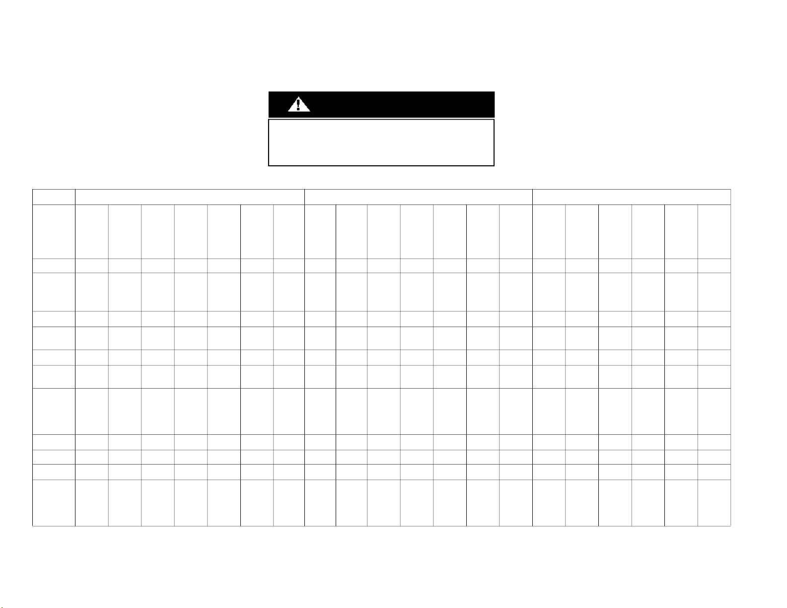
Table 11 — Remote Maintenance
Remote
Maintenance
Possible causes
of trouble
Unit will not start
Operation is
erratic,
unpredictable or
unit is
unresponsive
Cannot set
desired temp.
Unit is on
but the wind is
not cold (hot)
Unit runs, but
shortly stops
The unit starts up
and stops often
Unit runs
continuously
however
insufficient
cooling
(heating)
Cool can not
change to heat
Unit is noisy
Unit emits
bad odor
Test method/
remedy
Power failure
Test voltage
The main
power tripped
☆ ☆ ☆ ☆
Close the
power switch
Electrical Circuit Refrigerant Circuit Others
Loose
connections
Inspect
connections
- tighten
Faulty
transformer
Change the
transformer
The setting
The voltage is
too high or
Test voltage
The remote
too low
control is
powered off
☆ ☆ ☆
☆ ☆ ☆ ☆
Replace the
battery of the
remote control
Broken
remote
control
☆ ☆
Replace
remote
control
Dirty
Dirty
condenser
air filter
☆ ☆ ☆ ☆ ☆ ☆ ☆ ☆
☆
Clean
or
replace
fins
Clean
higher/lower
setting temp.
The ambient
temp is
temp. is too
high/low when
than the
the mode is
room's
(cooling/
heating)
Adjust the
cooling/
heating
☆ ☆ ☆
Turn the
AC later
Fan mode
Adjust to
Cool mode
SILENCE
function is
activated
(optional
function)
Turn off
SILENCE
function.
Frosting and
defrosting
frequently
Turn the
AC later
Heavy load
condition
Check the
heat load
Interference
Loose hold
down bolts
and/or screws
Tighten bolts
or screws
Not air tight
☆ ☆
Close all
windows and
doors
Air inlet or
outlet of either
unit is blocked
Remove the
obstacles
from cell
phones
towers and
remote
boosters
☆
Reconnect the
power or
press ON/
OFF button on
remote control
to restart
Shipping
plates
remained
attached
Remove
them
20 Specifications subject to change without notice. SM619PHA-03
Page 21

ERROR DIAGNOSIS AND TROUBLESHOOTING WITHOUT ERROR CODE (continued)
Table 12 — Field Maintenance
Field
Maintenance
Possible
causes
of trouble
Unit will not start
Compressor will
not start however
the fan runs
Compressor and
condenser
(outdoor) fan will
not start
Evaporator
(indoor)
fan will not start
Condenser
(outdoor) fan will
not start
Unit runs but
shortly stops
Compress or short
cycles due to
overload
High discharge
pressure
Low discharge
pressure
High suction
pressure
Low suction
pressure
Unit runs
continuously but
insufficient cooling
Too cool
Compressor is
noisy
Horizontal louver
can not revolve
Test method /
remedy
Power failure
☆ ☆
Test voltage
Blown fuse
or varistor
Inspect fuse
type & size
Loose
connections
☆ ☆ ☆ ☆
☆ ☆ ☆
Inspect
connections -
tighten
Shorted or
broken wires
Test circuits
with tester
Safety device
opens
☆ ☆ ☆ ☆ ☆
☆ ☆ ☆
☆ ☆ ☆ ☆
☆ ☆ ☆ ☆ ☆
Test continuity
of safety
device
Faulty
thermostat/
room temp
sensor
Test continuity
of thermostat /
sensor &
wiring
Wrong setting
place of temp
☆ ☆
Place the
temp. sensor
at the central
of air in- let
sensor
grille
Electrical Circuit
Faulty
transformer
Check control
circuit with
tester
Shorted or
open capacitor
Check
capacitor with
tester
Faulty
magnetic
contact for
compressor
☆ ☆
☆ ☆
Test continuity
of coil &
contacts
Faulty
magnetic
contact for fan
Test continuity
of coil &
contacts
Low voltage
Test voltage
Faulty
stepping motor
Replace the
stepping motor
Shorted or
grounded
compressor
Check
resistance with
Megger tester
Shorted or
grounded fan
motor
Check
resistance with
Megger tester
SM619PHA-03 Specifications subject to change without notice. 21
Page 22

ERROR DIAGNOSIS AND TROUBLESHOOTING WITHOUT ERROR CODE (continued)
Table 13 — Field Maintenance
Field Maintenance Refrigerant Circuit
Possible causes
of trouble
Unit will not start
Compressor will not
start however the
fan runs
Compressor and
condenser (outdoor)
fan will not start
Evaporator (indoor)
fan will not start
Condenser (outdoor) fan will not
start
Unit runs but
shortly stops
Compress or short
cycles due to
overload
High discharge
pressure
Low discharge
pressure
High suction
pressure
Low suction
pressure
Unit runs
continuously but
insufficient cooling
Too cool
Compressor is noisy
Horizontal louver
can not revolve
Test method /
remedy
Compressor
stuck
☆
Replace the
compressor
Insufficient
Refrigerant
Shortage
Leak test
Restricted
liquid line
☆ ☆ ☆ ☆ ☆ ☆
☆ ☆ ☆
☆ ☆
☆ ☆ ☆ ☆ ☆ ☆ ☆ ☆
☆ ☆ ☆ ☆ ☆ ☆ ☆ ☆ ☆
Replace the
restricted
part
Dry air filter
Clean or
replace
Dirty
evaporator
coil
Clean coil Check fan
air
through
evaporator
coil
Refrigerant
overcharge
Change
charged
refrigerant
volume
Dirty or
partially
blocked
condenser
☆ ☆ ☆ ☆ ☆ ☆
☆ ☆ ☆
☆ ☆
condenser
or remove
obstacle
Clean
Air or non-
condensible
gas in
refrigerant
cycle
Purge,
evacuate
and
recharge
Short
cycling of
condensing
air
Remove
obstruction
to air flow
High temp.
condensing
medium
Remove
obstruction
in air or
water flow
Insufficient
condensing
medium
Remove
obstruction
in air or
water flow
Broken
compressor
internal
parts
Replace
compressor
Insufficient
compressor
Test
compressor
efficiency
Expansion
valve
obstructed
Replace
valve
Expansion
valve or
capillary
tube closed
completely
Replace
valve
Leaking
power
element on
expansion
valve
Replace
valve
Power
installation
of feeler
bulb
Fix feeler
bulb
22 Specifications subject to change without notice. SM619PHA-03
Page 23
ERROR DIAGNOSIS AND TROUBLESHOOTING WITHOUT ERROR CODE (continued)
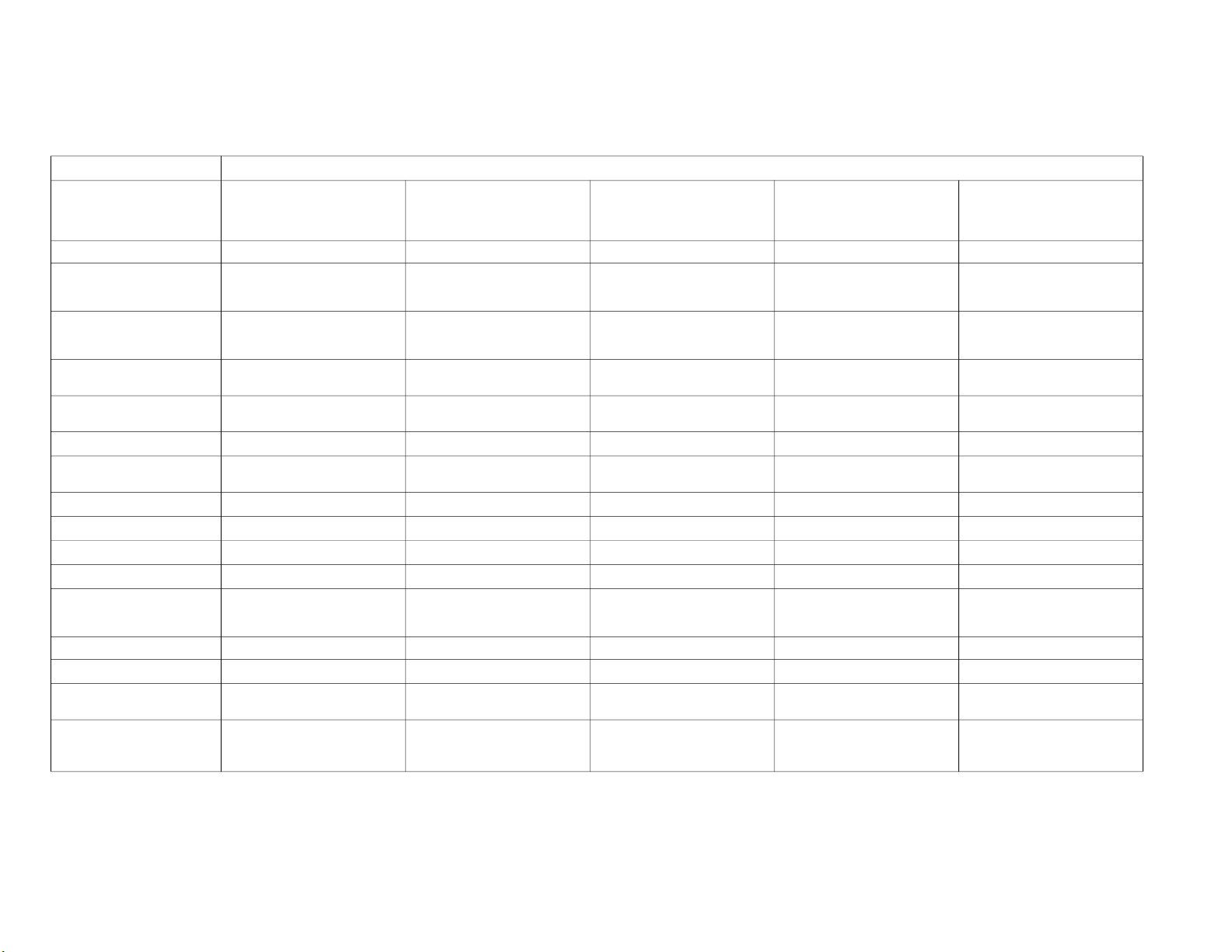
Table 14 — Field Maintenance
Field Maintenance Others
Possible causes
of trouble
Unit will not start
Compressor will not start
however the fan runs
Compressor and condenser
(outdoor) fan will not start
Evaporator (indoor) fan
will not start
Condenser (outdoor) fan will not
Unit runs but shortly stops
Compress or short cycles
High discharge pressure
Low discharge pressure
start
due to overload
High suction pressure
Low suction pressure
Unit runs continuously
but insufficient cooling
Too cool
Compressor is noisy
Horizontal louver
can not revolve
Heavy load condition Loosen hold down bolts and/or screws Shipping plates remain attached Poor choices of capacity
☆
☆ ☆
☆ ☆ ☆
Contact of piping with other piping or
external plate
Test method / remedy Check heat load Tighten bolts or screws Remove them
Choose AC of larger capacity or add
the number of units
Fix piping as not to touch each
other or external pipe
SM619PHA-03 Specifications subject to change without notice. 23
Page 24
QUICK MAINTENANCE BY ERROR CODE
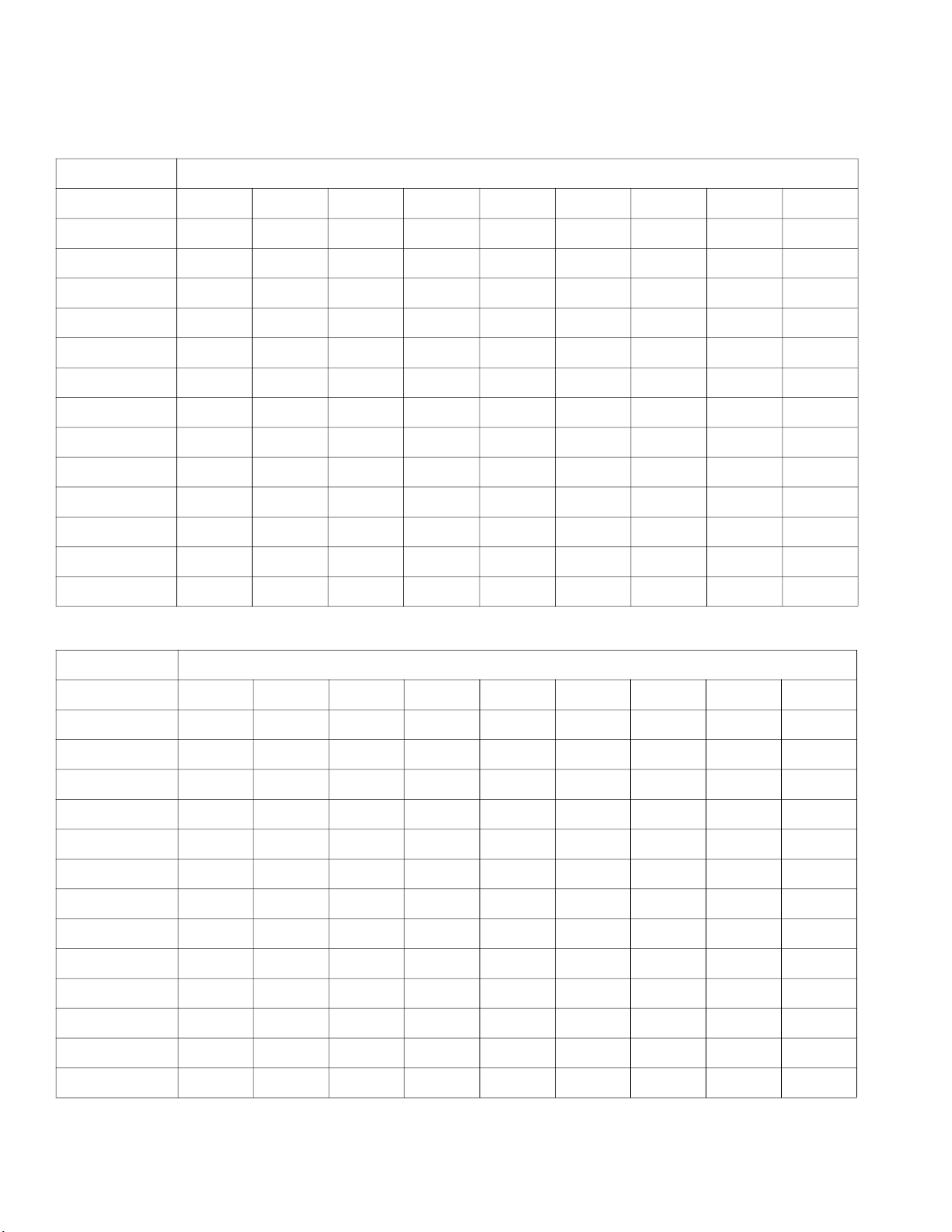
If you do not have the time to test whether specific parts are faulty, you can directly change the required parts according the error code.
You can find the parts to replace by error code in Tables 15 and 16.
Table 15 — Error Codes
Part Requiring
Replacement
E0 EA E1 E3 E4 E5 EB EF F0
ERROR CODE
Indoor PCB
Outdoor PCB x x
Display Board x x x x x x x x
Reactor x x
Indoor fan motor x x x
Outdoor fan motor x x x X x x x x x
Temperature sensor x x x x
T2 Sensor x x x x x x x x x
Additional refrigerant x x x x x x x x x
Compressor x x x x x x x x
IPM board x x x x x x x x x
Outdoor unit x x x x x x x x
Occupancy Sensor x x x x x x x x
x x
x x x x x
x x x x x x
x x x x x
x x x
Table 16 — Error Codes
Part Requiring
Replacement
F1 F2 F3 F4 F5 P0 P1 P2 P4
Error Code
Indoor PCB x x x x x x x x x
Outdoor PCB
Display Board x x x x x x x x x
Reactor x x x x x x
Indoor fan motor x x x x x x x x x
Outdoor fan motor x x x x
Temperature sensor
T2 Sensor x x x x x x x x x
Additional
refrigerant
Compressor x x x x x
IPM board x x x x x x
Outdoor unit x x x x x x x x x
Occupancy Sensor x x x x x x x x x
x x
x x x x
x x x X x x
x x x x x x x x x
x x
24 Specifications subject to change without notice. SM619PHA-03
Page 25
TROUBLESHOOTING BY ERROR CODE
Common Check Procedures
Temperature Sensor Check
Disconnect the temperature sensor from PCB, measure the resistance value with a tester.
Temperature Sensors.
Room temp. (T1) sensor,
Indoor coil temp. (T2) sensor,
Outdoor coil temp.(T3) sensor,
Outdoor ambient temp.(T4) sensor,
Compressor discharge temp.(Tp) sensor.
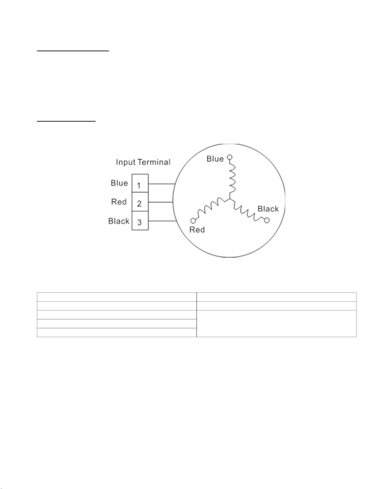
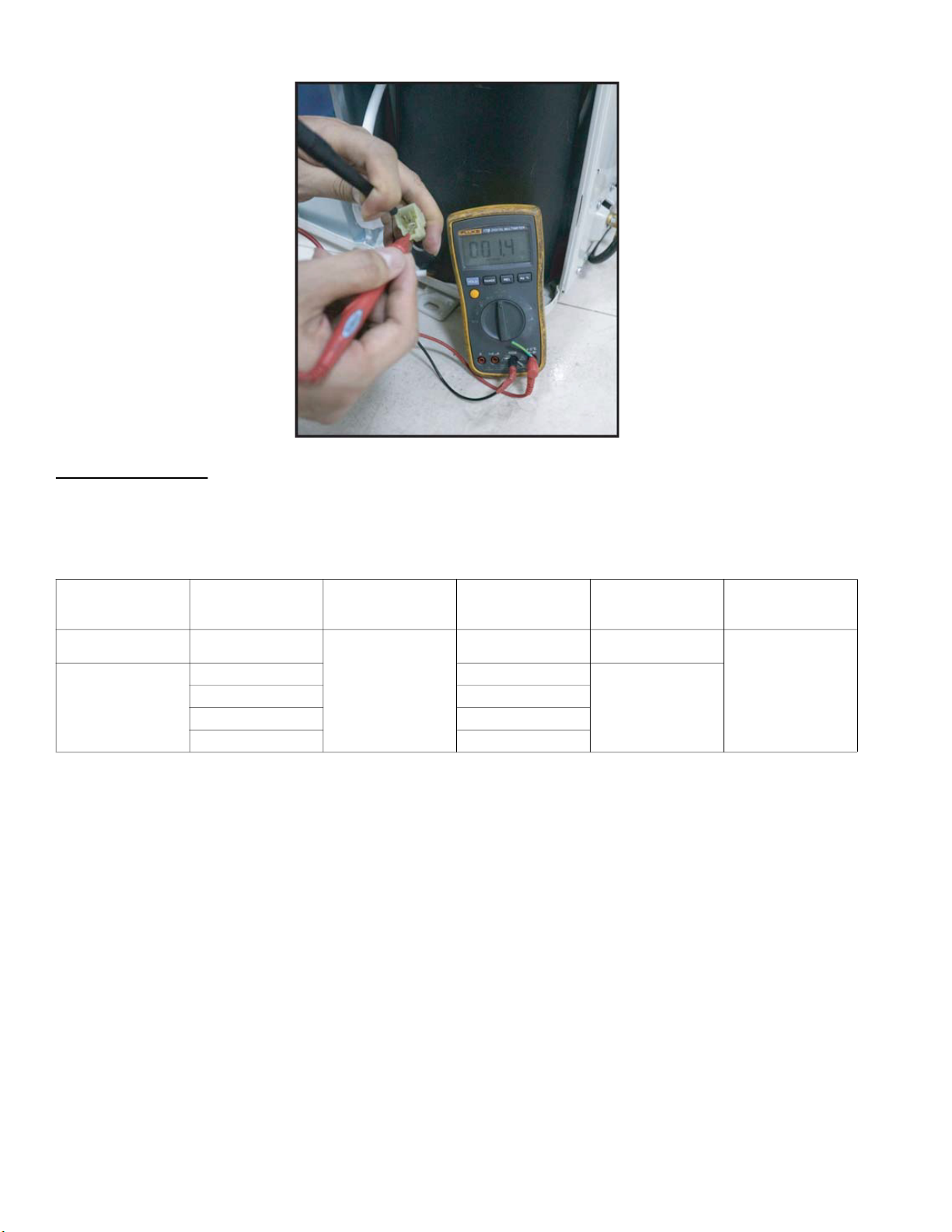
Measure the resistance value of each winding by using the multi-meter.
Compressor Checking
Measure the resistance value of each winding by using the tester.
Fig. 15 — Compressor Checking
Table 17 — Compressor Checking
POSITION RESISTANCE VALUE
ATM115D43UFZ2
Blue - Red
1.87
(20°C/68°FX)Blue - Black
Red - Blue
SM619PHA-03 Specifications subject to change without notice. 25
Page 26
IPM Continuity Check
Turn off the power. Allow the large capacity electrolytic capacitors to discharge completely, and dismount the IPM. Use a digital tester to
measure the resistance between P and UVWN; UVW and N.
Table 18 — IPM Continuity Check
Digital Tester
(+) Red (-) Black
P
Normal Resistance
Value
N U
U V
V W
W (+) Red
∞
(Several M
Digital Tester
(+) Red (-) Black
Normal Resistance
Value
∞
N
(Several M
26 Specifications subject to change without notice. SM619PHA-03
Page 27
DIAGNOSIS AND SOLUTION
The unit is operating normally.
NO
YES
Is it plugged correctly?
Correct the connection.
NO
Replace the indoor /outdoor
main PCB .
Shut o the power supply.
Wait 2 minutes then turn back on.
Does the error code still appear?
If the EEPROM chip is welded on the
main PCB, replace the main PCB.
Otherwise, check if the EEPROM chip
is plugged into the main PCB.
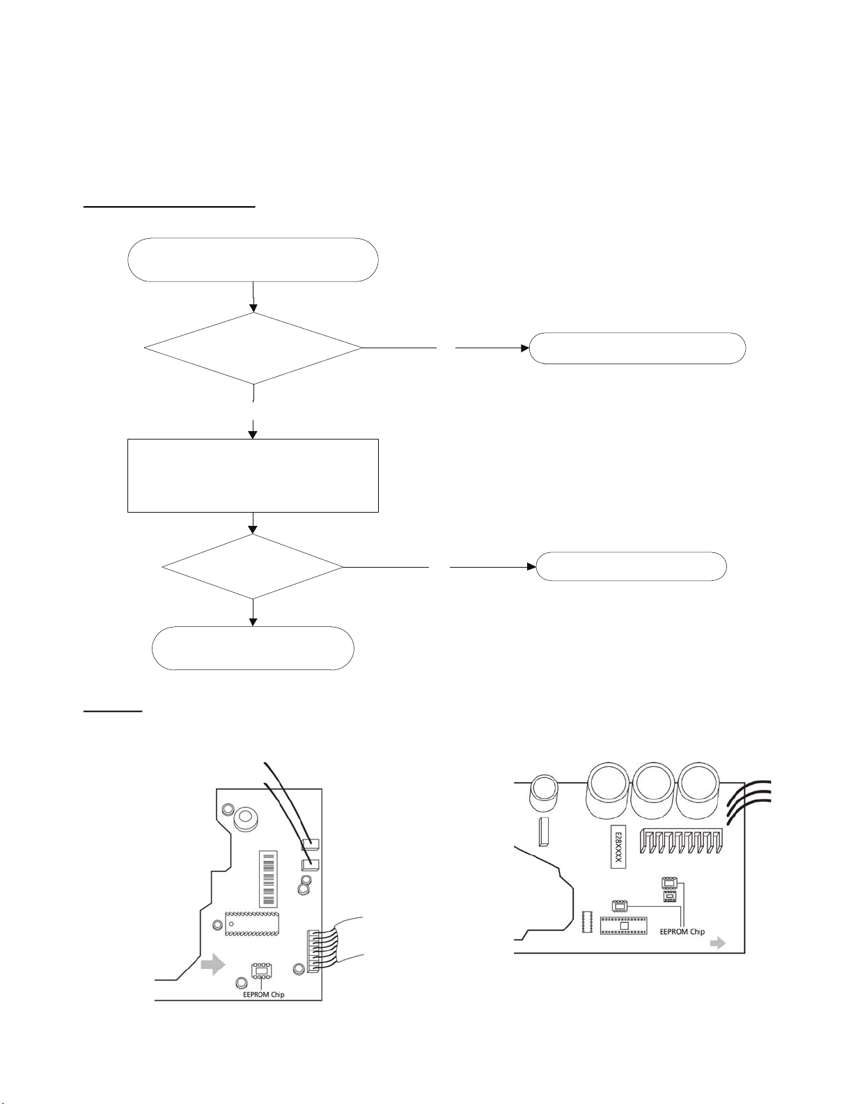
E0/F4/EA (EEPROM Parameter Error)
Description: Indoor or outdoor PCB main chip does not receive feedback from EEPROM chip.
Recommended parts to prepare:
• Indoor PCB
• Outdoor PCB
• Reactor
Troubleshooting and Repair:
Remarks:
The location of the EEPROM chip on the indoor and outdoor PCB is shown in Figures 16 and 17:
Fig. 16 —EEPROM Chip (Indoor Unit)
SM619PHA-03 Specifications subject to change without notice. 27
Fig. 17 —EEPROM Chip (Outdoor Unit)
Page 28
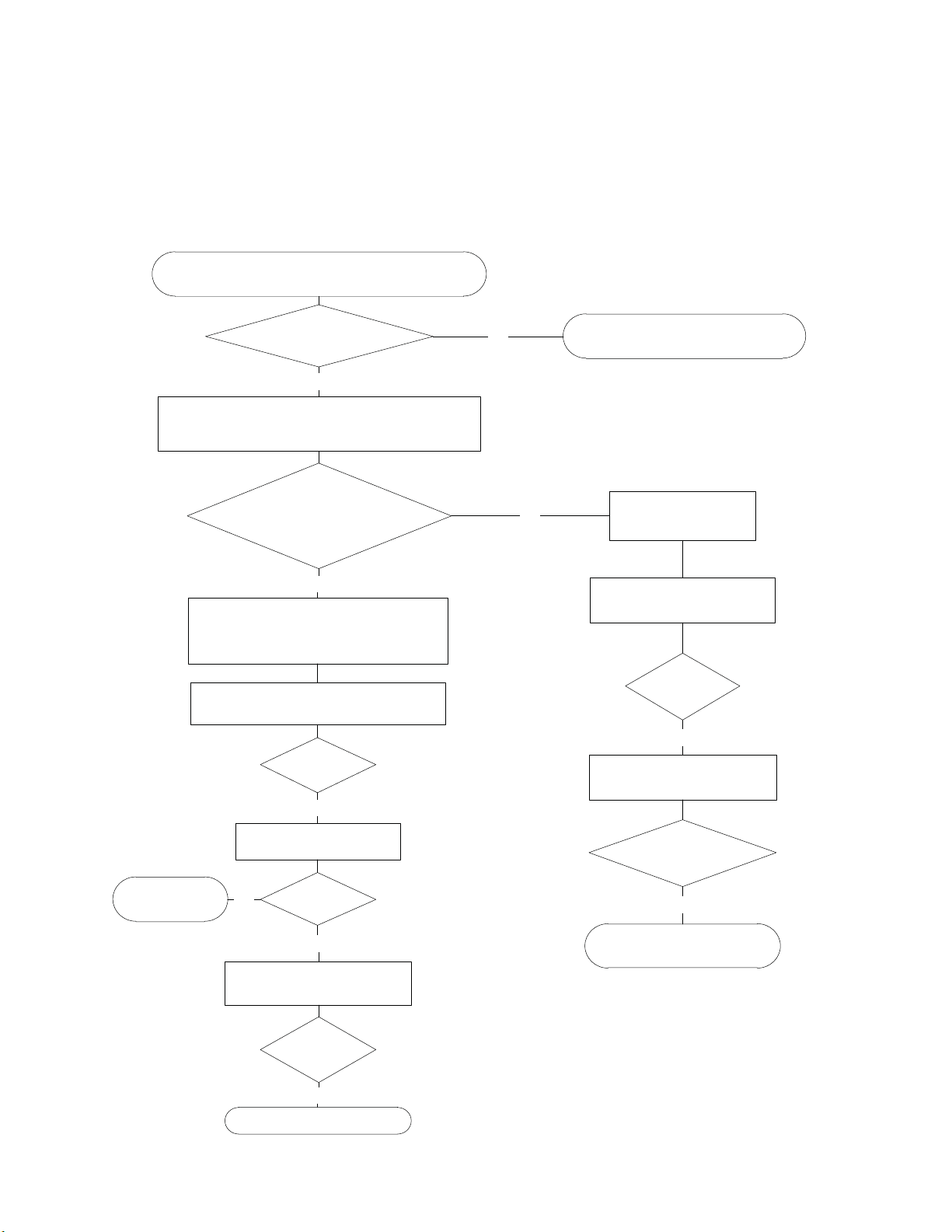
E1 (Indoor and Outdoor Unit Communication Error)
Does the problem remain? The unit is operating normally.NO
Measure Vs . ( Vs is the voltage between S and N on
the outdoor unit. Red pan-S, Black pan-N)
YES
Is the voltage moving
alternately between positive and
negative?
Is it normal?
YES
Is it normal?
YES
Is the error
resolved?
NO
NO
Check the indoor wiring
connections.
Is it normal?
YES
Is the error resolved?
NO
The voltage moves alternately with
positive value.
NO
The voltage is a
certain value.
NO
Power o. Wait 2 minutes then power back on.
Check the outdoor wiring connection.
Check the reactor.
Replace the
reactor.
Replace the outdoor PCB.
Power on.
Replace the indoor PCB.
Replace the outdoor PCB.
Replace the indoor PCB.
Power on.
Description: The indoor unit has not received feedback from the outdoor unit for 150 seconds, four consecutive times.
Recommended parts to prepare:
• Indoor PCB
• Outdoor PCB
• Reactor
Troubleshooting and Repair:
28 Specifications subject to change without notice. SM619PHA-03
Page 29
E1 (Indoor and Outdoor Unit Communication Error) (continued)
Remarks:
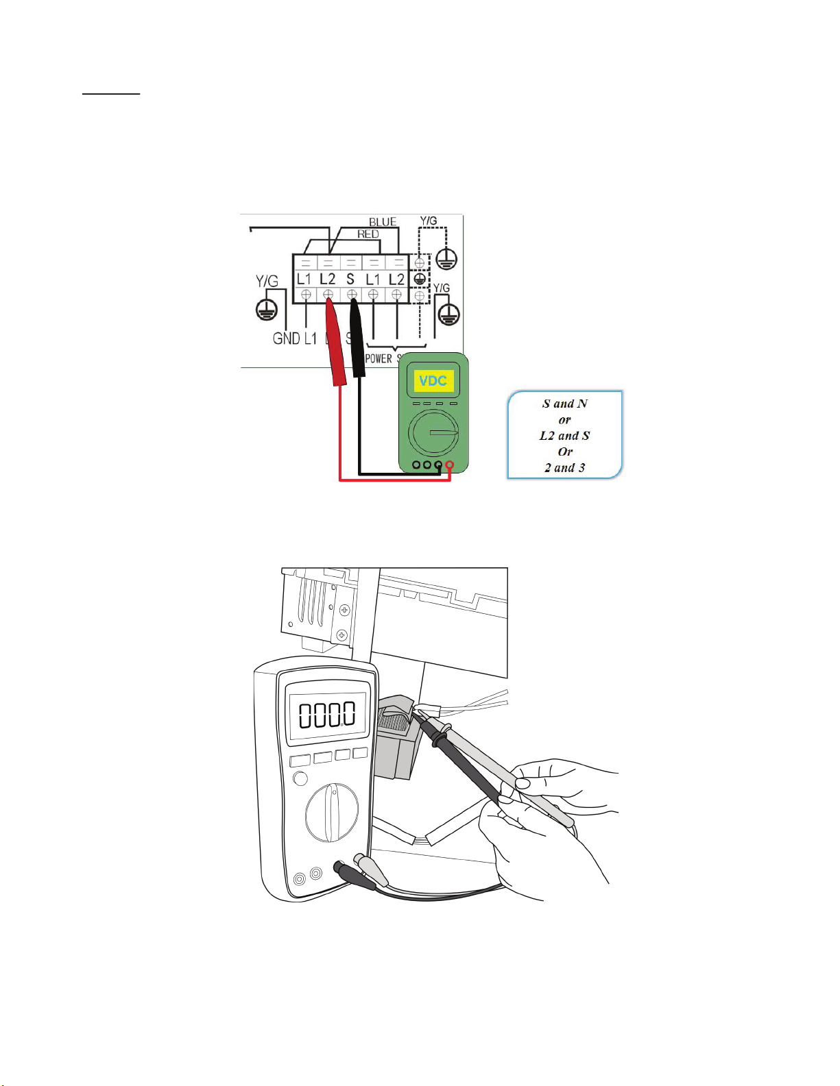
• Use a multimeter to test the DC voltage between the outdoor unit’s 2 port and 3 port. The red pin of multimeter connects with the 2 port
while the black pin is for 3 port.
• When the air conditioner is normal running, the voltage is moving alternately as positive values and negative values.
• If the outdoor unit has a malfunction, the voltage has always been the positive value.
• If the indoor unit has malfunction, the voltage is a fixed value.
Fig. 18 — Multimeter
• Use a multimeter to test the reactor resistance that does not connect with the capacitor.
• The normal value should be around zero ohm otherwise the reactor is malfunctioning.
Fig. 19 — Multimeter
SM619PHA-03 Specifications subject to change without notice. 29
Page 30
E2 (Zero crossing detection error diagnosis and solution)
Check the connections and
power supply.
Correct the connections. Power on the
unit when the power supply is good.
NO
Indoor main PCB is defective.
Replace the indoor main PCB.
YES
Is it normal?
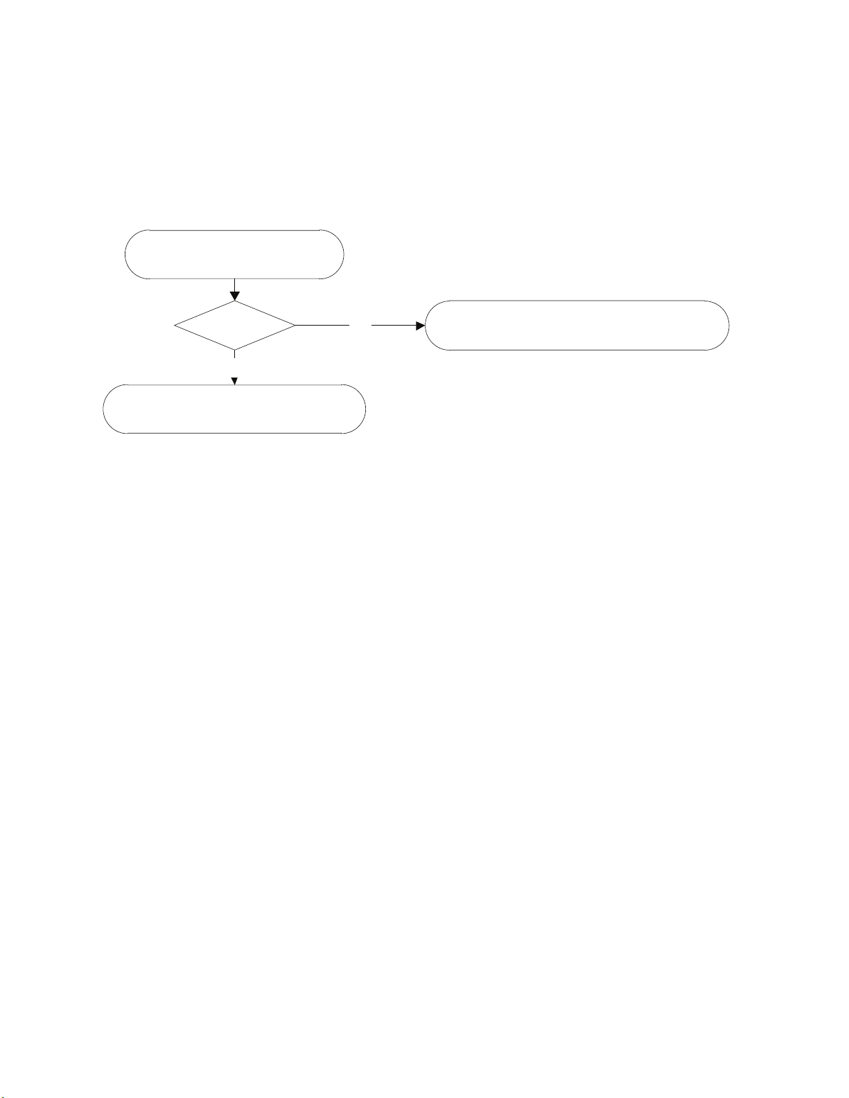
Description: When PCB does not receive zero crossing signal feedback for 4 minutes or the zero crossing signal time interval is abnormal.
Recommended parts to prepare:
• Connection wires
• PCB
Troubleshooting and repair:
30 Specifications subject to change without notice. SM619PHA-03
Page 31
E3/F5 (Fan speed is operating outside of the Normal Range)
YES
Is it within normal parameters?
Replace the fan motor.
Does the problem exist? The unit is operating normally.NO
YES
Does it turn easily?
Find the cause of the problem and resolve.NO
Check the fan motor wiring.
YES
Is it improperly wired ? Ensure proper connections.
Measure the voltage for
the fan motor from the PCB.
YES
Replace the indoor /outdoor PCB.
NO
Power o. Wait 2 minutes then restart.
Shut o the power supply.
Rotate the fan by hand.
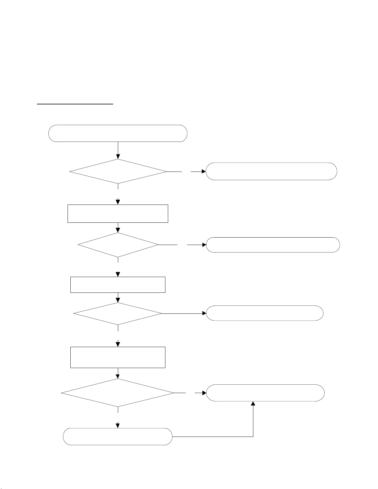
Description: When the indoor fan speed maintains a low speed (ex. 300RPM) or a speed that’s too high (ex.1500RPM) for a certain time, the
unit stops and the LED displays the failure (E3). When the outdoor fan speed registers below 200RPM or over 1500RPM for an extended
period of time, the unit stops and the LED displays the failure (F5).
Recommended parts to prepare:
• Wiring
• Faulty fan assembly
• Faulty fan motor
• Faulty PCB
Troubleshooting and Repair:
SM619PHA-03 Specifications subject to change without notice. 31
Page 32
Index
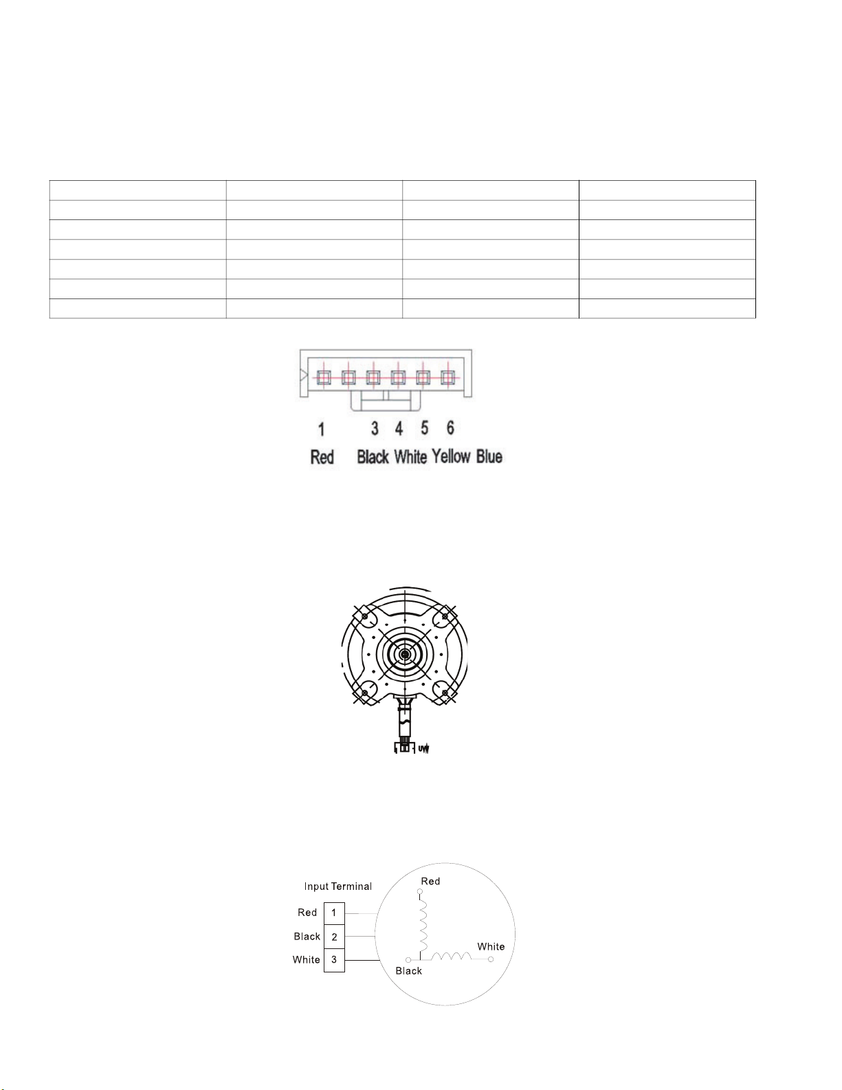
1. Indoor or Outdoor DC Fan Motor (control chip is in the fan motor)
Power on and when the unit is in standby, measure the voltage of pin1-pin3, pin4-pin3 in the fan motor connector. If the value of the
voltage is not in the range shown in Table 19, the PCB must has problems and need to be replaced.
DC motor voltage input and output (voltage: 220-240V~):
Table 19 — Voltage
NO. COLOR SIGNAL VOLTAGE
1 Red Vs/Vm 280V~380V
2 --- --- ---
3 Black GND 0V
4 White Vcc 14-18.5V
5 Yellow Vsp 0~5.6V
6 Blue FG 14-18.5V
Fig. 20 — Indoor DC Fan Motor
2. Outdoor DC Fan Motor (control chip is in outdoor PCB)
Power on and check if the fan can run normally, if the fan can run normally, the PCB must have a problem and needs to be replaced,
If the fan can not run normally, measure the resistance of each pin (two). If the resistance is not equal to each other, the fan motor must
have a problem and needs to be replaced, otherwise the PCB must has problems and needs to be replaced.
Fig. 21 — Outdoor DC Fan Motor
3. Indoor AC Fan Motor
Power on and set the unit running in FAN mode at the high fan speed. After running for 15 seconds, measure the voltage of pin1 and
pin2. If the value of the voltage is less than 100V(208~240V power supply) or 50V(115V power supply), the PCB must has problems
and needs to be replaced.
Fig. 22 — Indoor AC Fan Motor
32 Specifications subject to change without notice. SM619PHA-03
Page 33
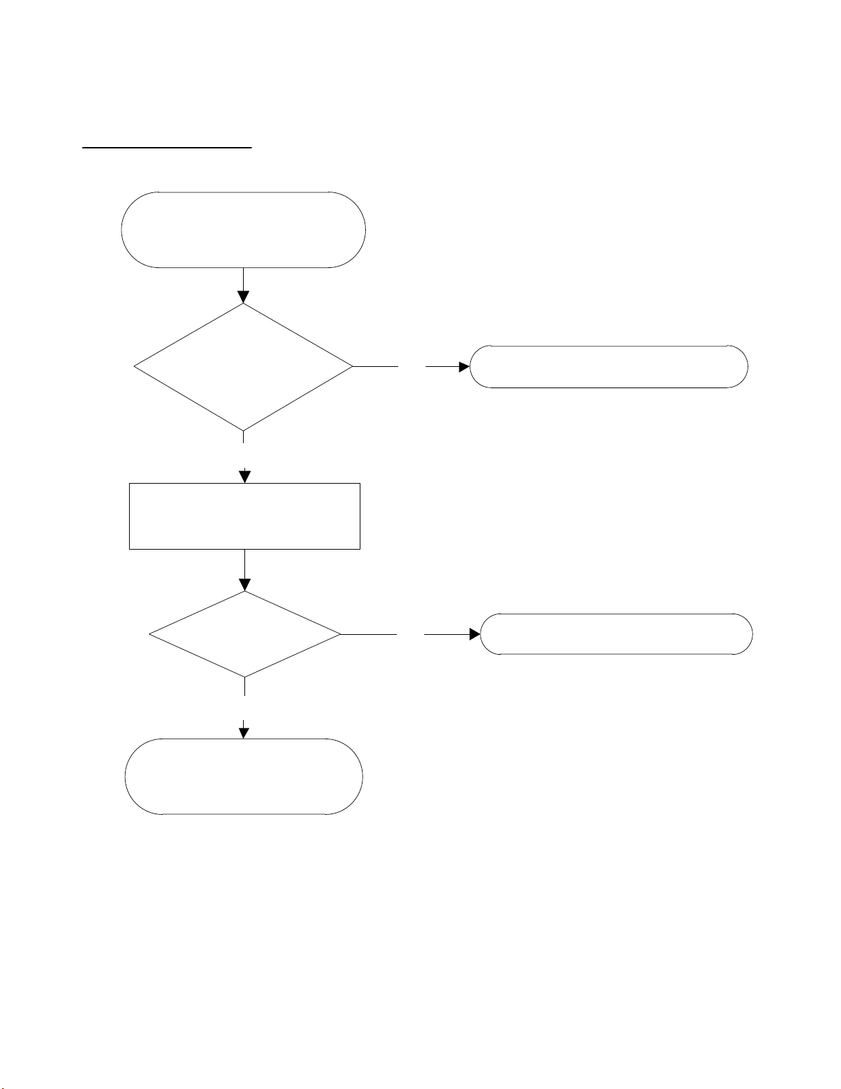
EF (Occupancy Sensor Module Error Diagnosis and Solution)
NO
YES
NO
YES
Power o.
Wait 2 minutes then restart.
Is the unit still
displaying an error code?
The unit is operating as designed.
Check the Occupancy Sensor
module wiring.
Is it good?
Ensure proper connections.
Replace the
Occupancy Sensor module.
Description: If the Occupancy Sensor module malfunctions, the LED displays the failure.
Recommended parts to prepare:
• Occupancy Sensor
Troubleshooting and Repair:
SM619PHA-03 Specifications subject to change without notice. 33
Page 34
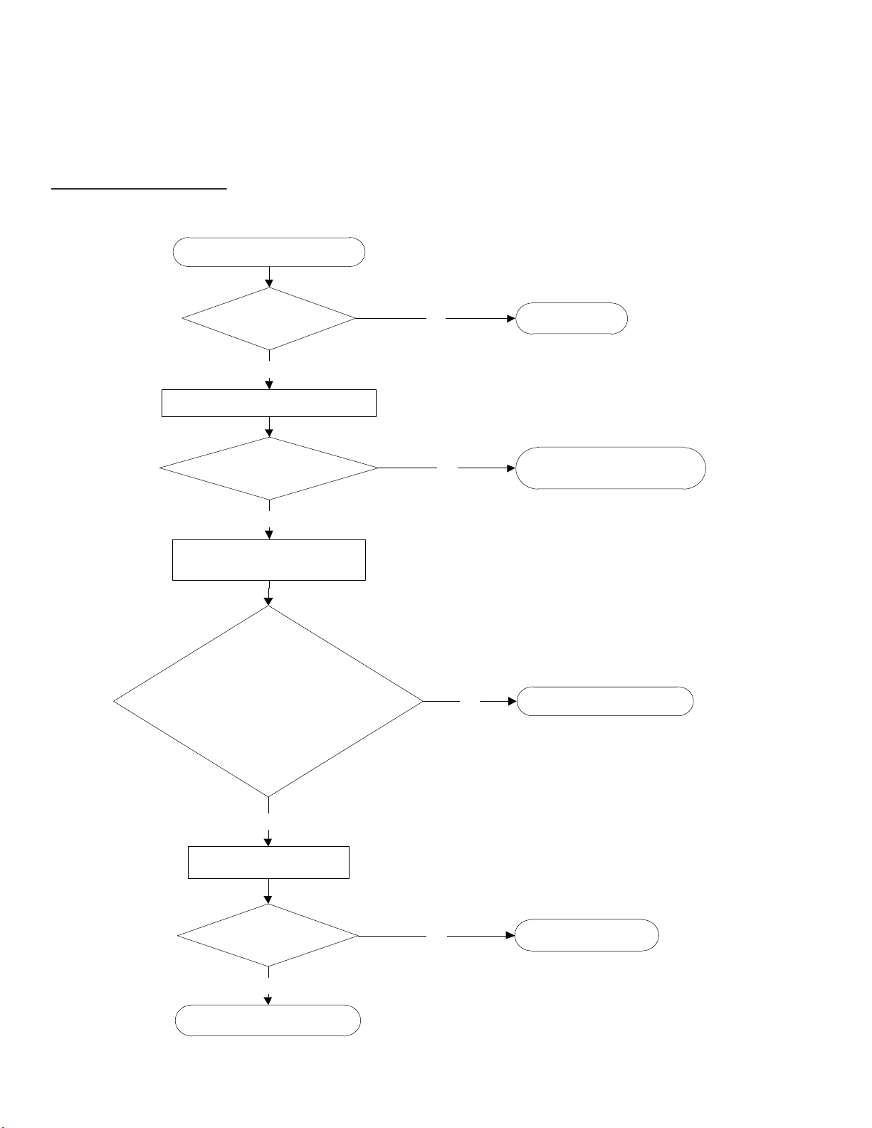
P1 (Over voltage or too low voltage protection diagnosis and solution)
Check the power supply.
Is it in working order ?
NO
Check the connections and wires.
YES
Are they in working order ?
Ensure proper connections or
replace the wires.
NO
Power on and measure the
voltage between P and N.
YES
Replace the IPM board.NO
Check the reactor.
YES
Is it in working order?
Replace outdoor PCB.NO
Replace the reactor.
YES
Turn o the unit.
While the unit is in standby,
is the voltage between P and N around
DC 310V, 340V or 380V? On unit start up
is the unit in the 220V~400 range?
Description: Abnormal increases or decreases in voltage are detected by checking the specified voltage detection circuit.
Recommended parts to prepare:
• Power supply issues
• System leakage or blockage
• Faulty PCB
Troubleshooting and Repair:
34 Specifications subject to change without notice. SM619PHA-03
Page 35
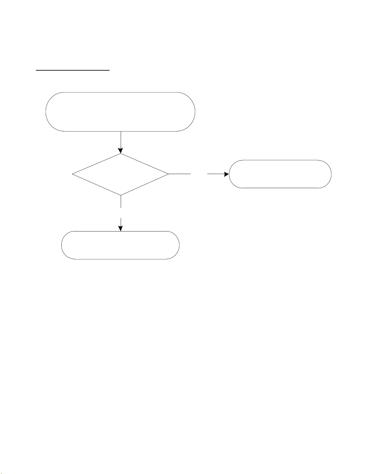
P2 (High temperature protection of IPM module diagnosis and solution)
Check the fastening screws on the
PCB and IPM radiator.
Are they
fixed tightly?
Replace the outdoor
control PCB.
Tighten the screws and apply
silicon grease.
NO
YES
Description: If the temperature of IPM module is higher than limited value, the LED displays this failure code.
Recommended parts to prepare:
• Faulty PCB
• Connection problems
Troubleshooting and Repair:
SM619PHA-03 Specifications subject to change without notice. 35
Page 36
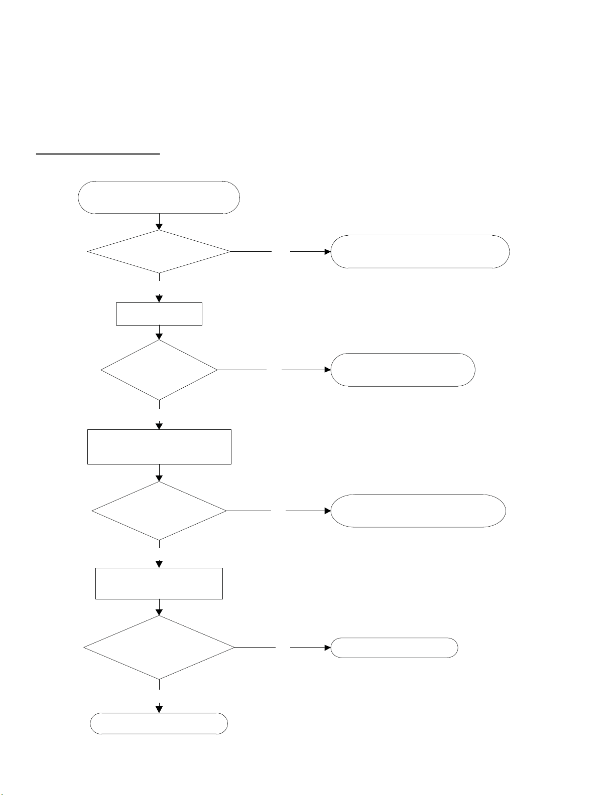
P4 (Inverter compressor drive error diagnosis and solution)
Check the wiring between the
PCB and compressor.
Is it improperly wired ?
Ensure proper connections or replace
the wires and connectors.
YES
Check the IPM.
NO
Is it functioning
properly?
Replace the IPM board or
replace the outdoor PCB.
NO
Check the outdoor fan and
the outdoor unit ventilation.
YES
Is it functioning
properly?
Please refer to “Fan Speed
Malfunction” solution.
NO
Check the compressor
resistance values.
YES
Are they within
acceptable parameters ?
Replace the compressor.NO
Replace the outdoor PCB.
YES
Description: If the temperature of IPM module is higher than limited value, the LED displays this failure code.
Recommended parts to prepare:
• Wiring mistake
• PM malfunction
• Outdoor fan assembly faulty
• Compressor malfunction
• Outdoor PCB faulty
Troubleshooting and Repair:
36 Specifications subject to change without notice. SM619PHA-03
Page 37
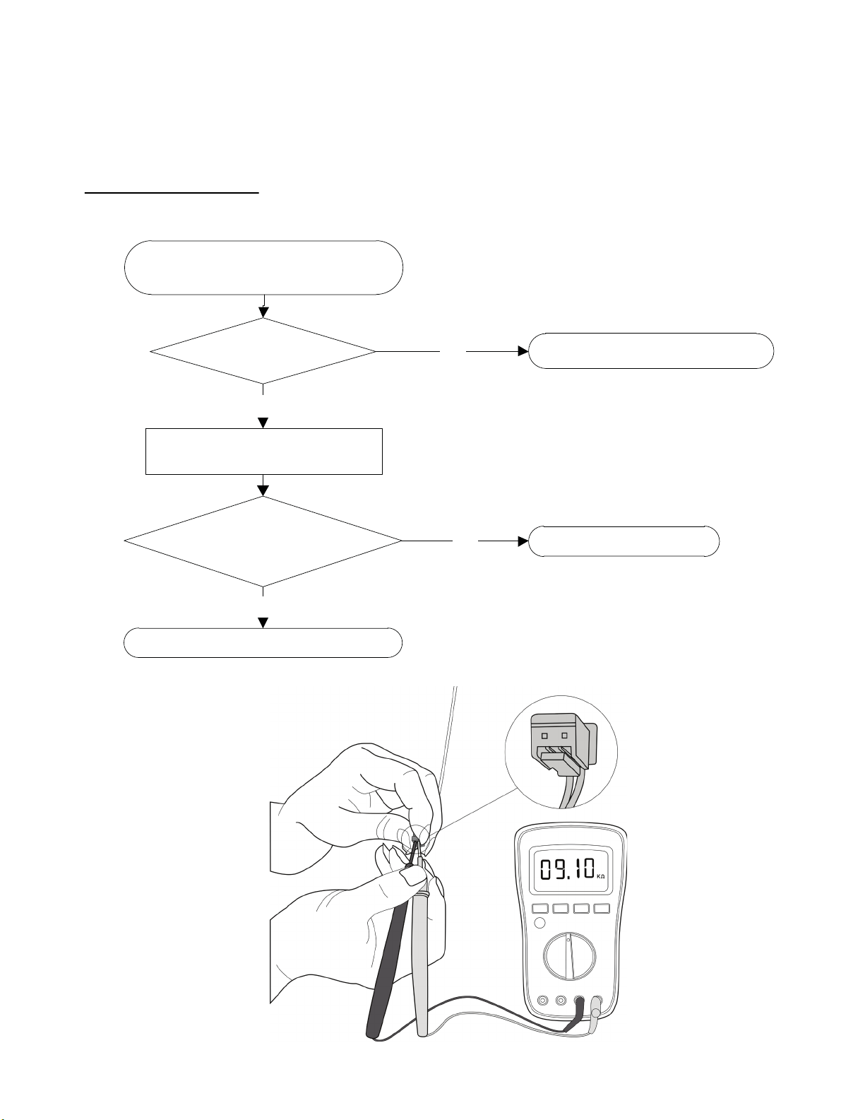
E4/E5/F1/F2/F3 (Open circuit or short circuit of temperature sensor diagnosis and solution)
Check the connection between
temperature sensor and PCB.
Replace indoor or outdoor PCB.
Is it within acceptable
parameters?
Is it properly wired ?
Ensure proper connections .
NO
Measure the resistance value
of the sensor.
YES
Replace the sensor.NO
YES
Description: If the sampling voltage is lower than 0.06V or higher than 4.94V, the LED displays the failure.
Recommended parts to prepare:
• Wiring mistake
• Faulty sensor
• Faulty PCB
Troubleshooting and Repair:
SM619PHA-03 Specifications subject to change without notice. 37
Fig. 23 —Multimeter
Page 38
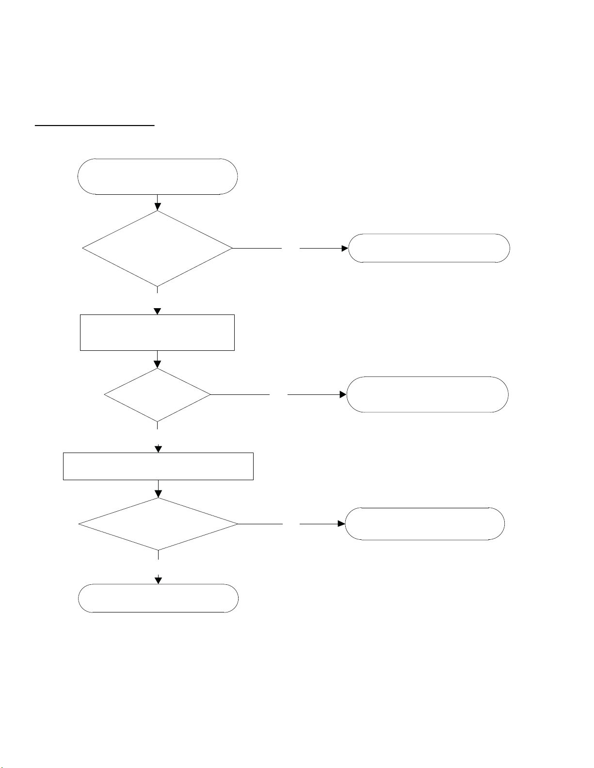
Eb (Communication error between the Indoor PCB and Display Board)
Is it still displaying
the error code ?
The unit operates normally.NO
Check the wirings and
connection.
YES
Is it normal?
Correct the connection
or replace the wirings.
NO
Replace the indoor main PCB.
YES
Is the problem solved?
Replace the display board.NO
The unit operates normally.
YES
Power o. Wait 2 minutes
then restart.
Description: Indoor PCB does not receive feedback from the display board.
Recommended parts to prepare:
• Wiring mistake
• PCB faulty
• Display board malfunction
Troubleshooting and Repair:
38 Specifications subject to change without notice. SM619PHA-03
Page 39
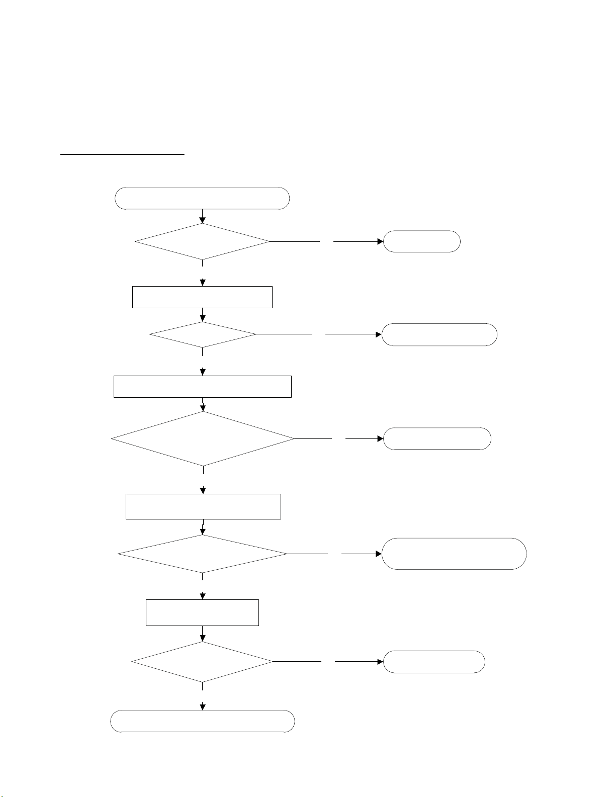
F0 (Overload current protection diagnosis and solution)
Check the power supply.
Do any exist?
Are they within acceptable
parameters?
Are they properly connected?
Is it in working order?
Replace the outdoor unit.
Is it in working order?
Check system for blockages .
YES
Stop the unit .
NO
Clear the blockage.NO
Check the compressor resistance values.
YES
Replace the compressor.NO
Check the connections and wires.
YES
Ensure proper connections or
replace the wires.
NO
Check the reactor.
YES
YES
Replace outdoor PCB.
NO
Description: An abnormal current rise is detected by checking the specified current detection circuit.
Recommended parts to prepare:
• Power supply problems
• System blockage
• Faulty PCB
• Wiring mistake
• Compressor malfunction
Troubleshooting and Repair:
SM619PHA-03 Specifications subject to change without notice. 39
Page 40
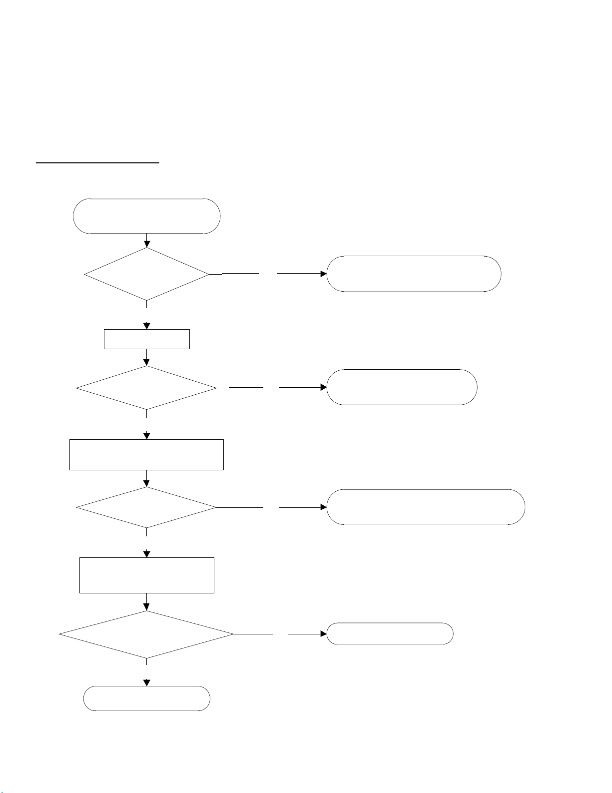
P0 (IPM malfunction or IGBT over-strong current protection diagnosis and solution)
Check the wiring between
PCB and compressor.
Does an error exist?
Ensure proper connections or
replace the wires and connectors.
YES
Check the IPM.
NO
Is it in working order?
Replace the IPM board or
replace the outdoor PCB.
NO
Check the outdoor fan and the
outdoor unit ventilation.
YES
Is it in working order?
Refer to the “Fan Speed is Out of Control”
solution.
NO
Check the compressor
resistance values.
YES
Are they within
acceptable parameters?
Replace the compressor.
Replace the outdoor PCB.
YES
NO
Description: When the voltage signal the IPM sends to the compressor drive chip is abnormal, the display LED displays “P0” and the air
conditioner turns off.
Recommended parts to prepare:
• Wiring mistake
• IPM malfunction
• Faulty outdoor fan assembly
• Compressor malfunction
• Faulty outdoor PCB
Troubleshooting and Repair:
40 Specifications subject to change without notice. SM619PHA-03
Page 41
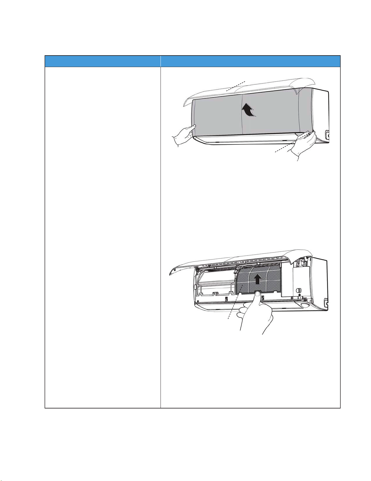
DISASSEMBLY INSTRUCTIONS
noitartsullIerudecorP
1) Hold the front panel by the tabs on
both sides and lift it.
2) Push up the bottom of the air filter
while pressing the buttom of the
unit, and then pull the air
filter out (downwards).
Front Panel
Ta b
Filter
Indoor Unit Sizes 09K-12K (Front Panel)
SM619PHA-03 Specifications subject to change without notice. 41
Page 42
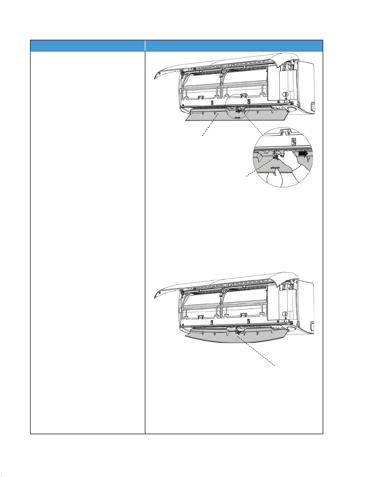
Indoor Unit Sizes 09K-12K (Front Panel) (continued)
noitartsullIerudecorP
3) Open the horizontal louver and push
the hook towards the right to open.
4) Bend the horizontal louver lightly with
both hands to loosen the hooks, then
remove the horizontal louver.
Hook
Horizontal Louver
Hook
42 Specifications subject to change without notice. SM619PHA-03
Page 43
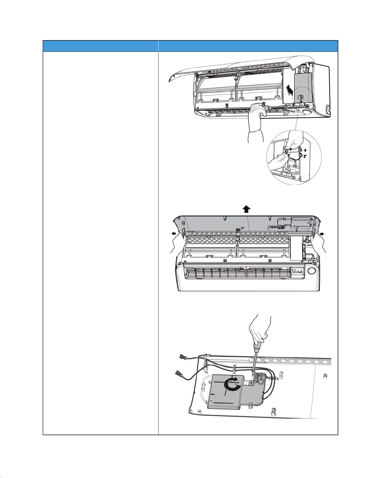
Indoor Unit Sizes 09K-12K (Front Panel) (continued)
noitartsullIerudecorP
5)
Remove the screw (1) then remove the
electrical cover.
6) Disconnect the two connectors on the
display board.
7) Slide the front panel side to side to
release each axis.
8) Remove the screw (1) and rotate the
display board clockwise. Next, remove
the clips.
SM619PHA-03 Specifications subject to change without notice. 43
Page 44
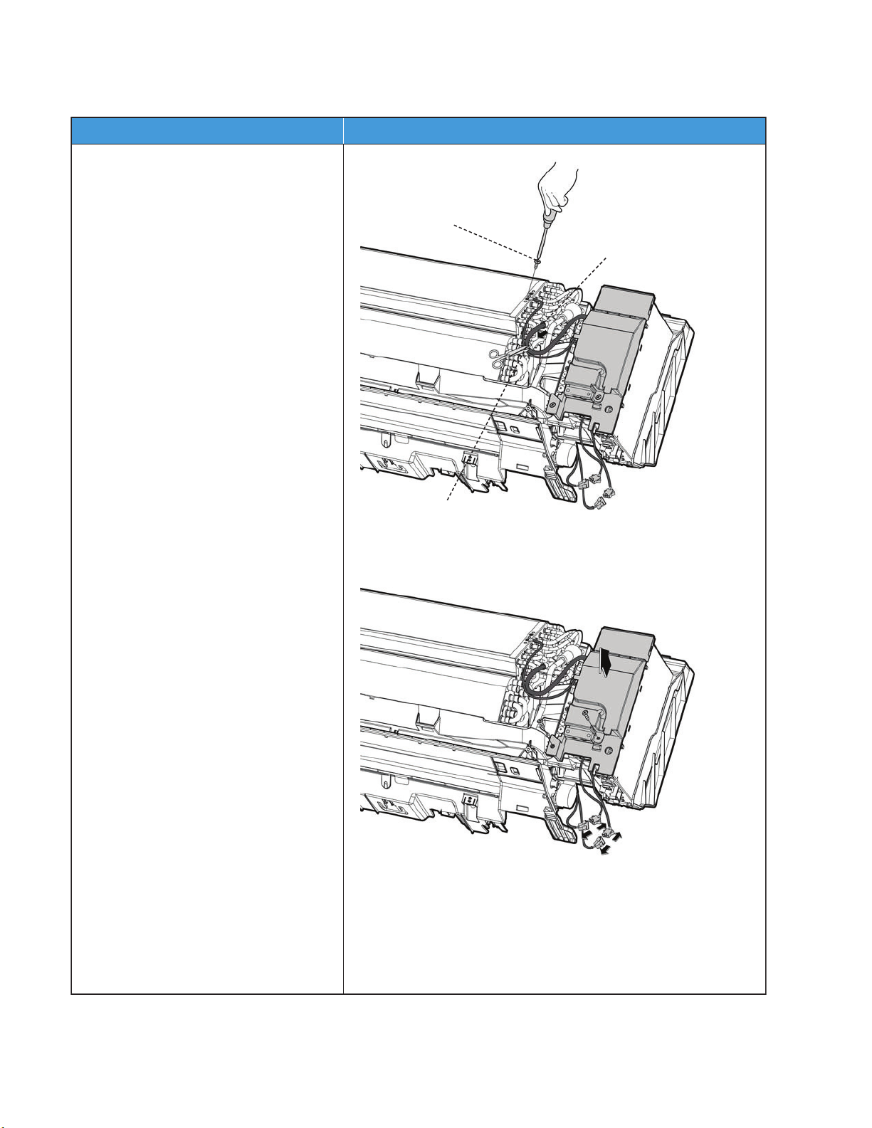
Indoor Unit Sizes 09K-12K (Electrical Parts) (Anti-static gloves must be worn)
noitartsullIerudecorP
1) Cut the ribbon with a shear, then pull
out the coil temperature sensor (T2).
2) Remove the screws (2) used for
the ground connection.
3) Remove the screws (1 for the
electronic cover and 1 for the terminal
cover). Next, remove the electronic box
cover and the terminal cover along
the direction indicated in the image
(on the right side) to remove it.
4) Disconnect the fan motor connector
and the step motor.
Ribbon
Ground Screws
T2 Sensor
NOTE: Remove the front panel (refer to the front panel removal steps) before disassembling electrical parts.
44 Specifications subject to change without notice. SM619PHA-03
Page 45
Indoor Unit Sizes 09K-12K (Electrical Parts) (Anti-static gloves must be worn) (continued)
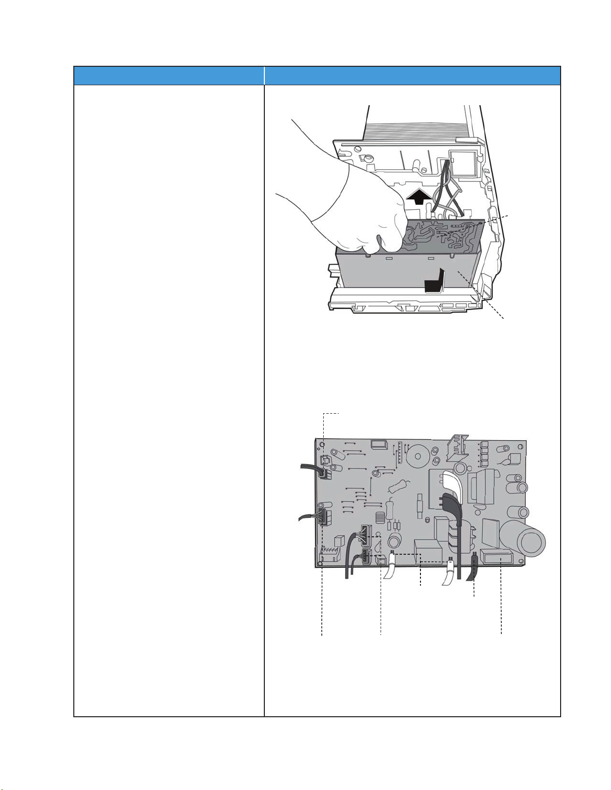
noitartsullIerudecorP
5) Disconnect the wires. Next, remove the
electronic main box.
6) Pull out the electrical control box along
the direction indicated in the image to
remove it.
7) Each port connector is indicated in the
image to the right.
Main Board
Electronic Box
Swing Motor
Pipe Temperature Sensor
Display Board
Indoor Fan Motor
Terminals
Ground Wire
SM619PHA-03 Specifications subject to change without notice. 45
Page 46
Indoor Unit Sizes 09K-12K (Evaporator)
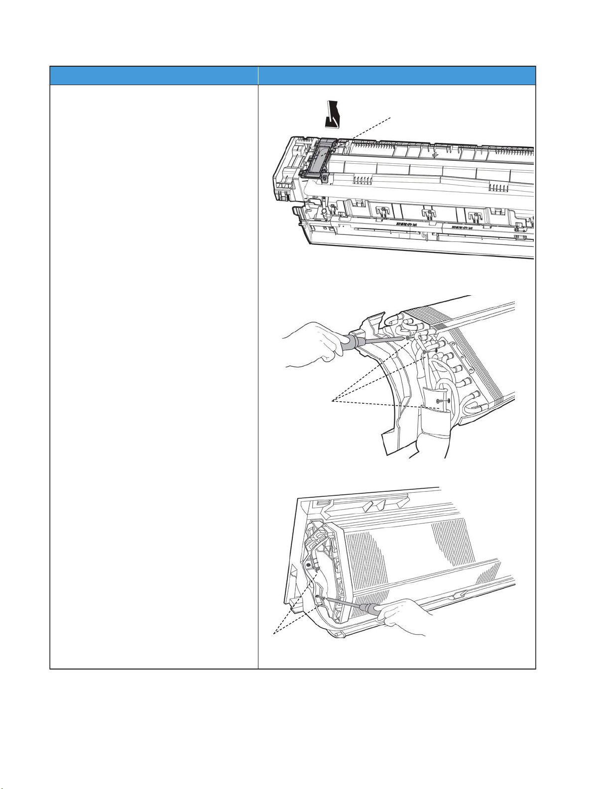
noitartsullIerudecorP
1) Disassemble the pipe holder located at the
rear of the unit.
2) Remove the screws (3) on the evaporator
located on the fixed plate.
3) Remove the screws (2) on the evaporator
located at the base of the bearing side.
Pipe Holder
Screws
Screws
46 Specifications subject to change without notice. SM619PHA-03
Page 47
Indoor Unit Sizes 09K-12K (Evaporator) (continued)
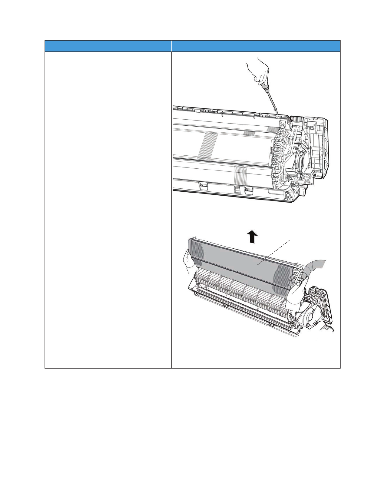
noitartsullIerudecorP
4) Remove the screw (1) on the evaporator
located at the top of the evaporator.
5) Remove the evaporator.
Evaporator
SM619PHA-03 Specifications subject to change without notice. 47
Page 48
Indoor Unit Sizes 09K-12K (Fan Motor and Fan)
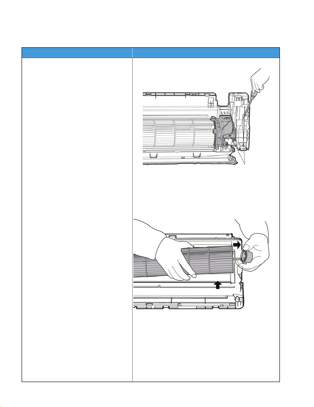
noitartsullIerudecorP
1) Remove the screws (2) and remove the
fixing board of the fan motor.
2) Remove the bearing sleeve.
Screws
NOTE: Remove the front panel, electrical parts and evaporator (refer to front panel, electrical parts, and evaporator
removal steps) before disassembling fan motor and fan.
48 Specifications subject to change without notice. SM619PHA-03
Page 49
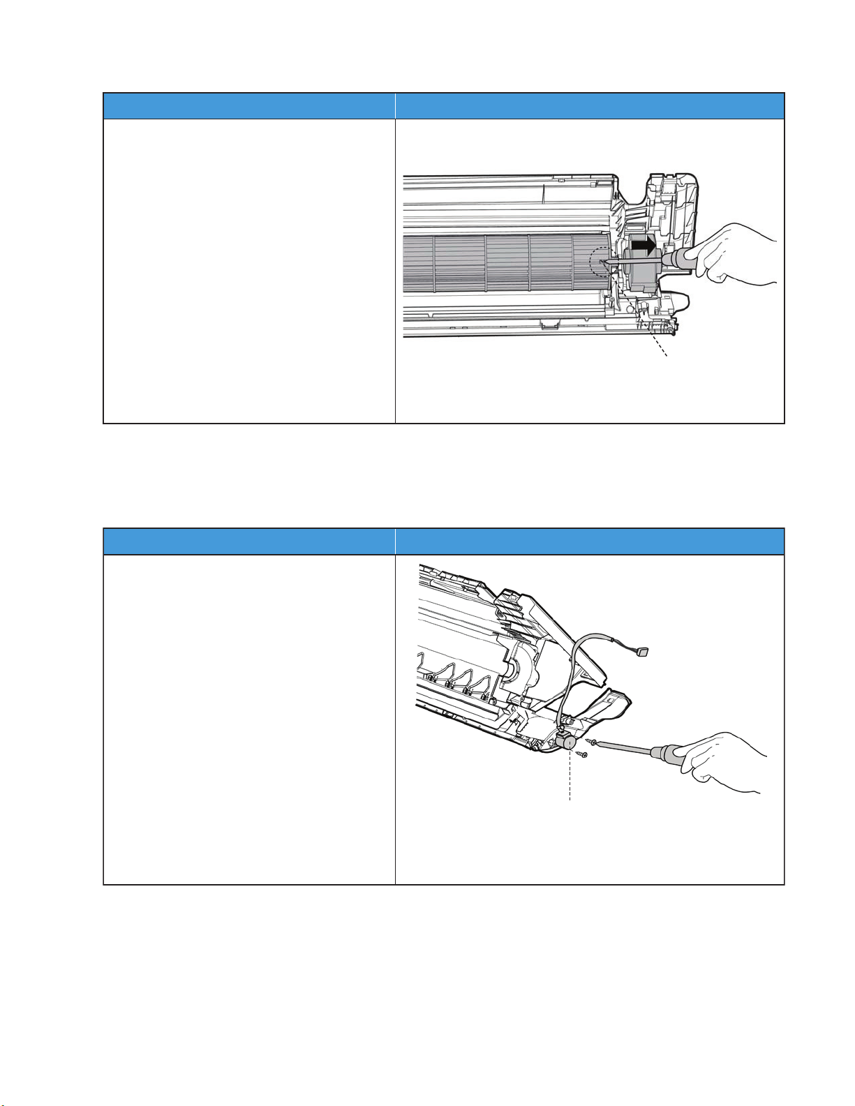
Indoor Unit Sizes 09K-12K (Fan Motor and Fan) (continued)
noitartsullIerudecorP
3) Remove the set screw.
4) Pull out the fan motor and fan assembly
from the side.
Fixing Screw
noitartsullIerudecorP
1) Remove the screws (2), then remove the
stepping motor.
Stepping Motor
Indoor Unit Sizes 09K-12K (Step Motor)
NOTE: Remove the front panel and electrical parts (refer to the front panel, electrical parts removal steps) before
disassembling the step motor.
SM619PHA-03 Specifications subject to change without notice. 49
Page 50
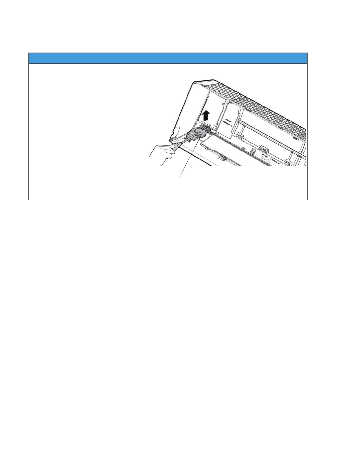
Indoor Unit Sizes 09K-12K (Occupancy Sensor)
noitartsullIerudecorP
1) Remove the screw (1), then remove the
Occupancy Sensor.
Occupancy Sensor
NOTE: Remove the front panel and electrical parts (refer to the front panel, electrical parts, evaporator and fan motor
and fan removal steps) before disassembling the occupancy sensor.
50 Specifications subject to change without notice. SM619PHA-03
Page 51
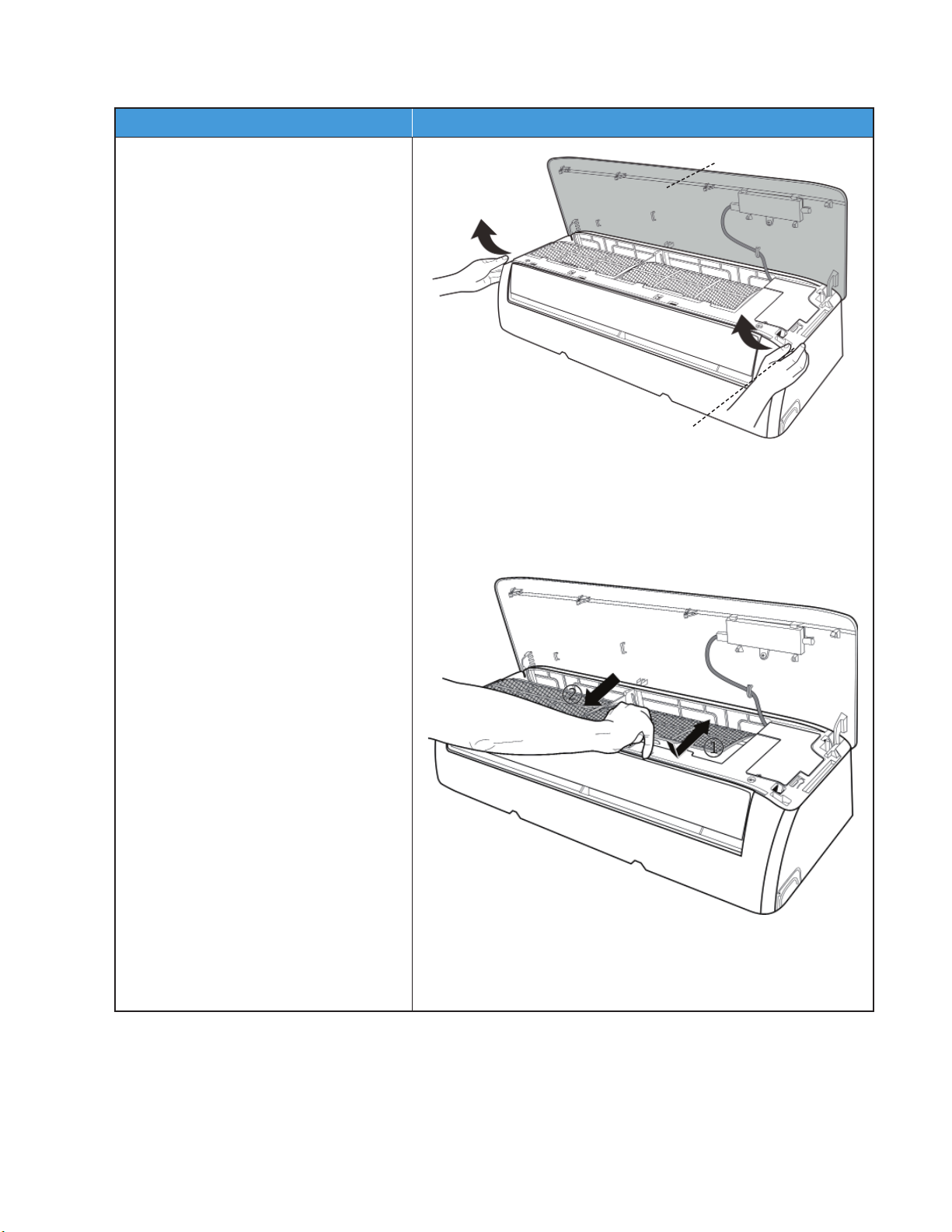
Indoor Unit Sizes 18K-24K (Front Panel)
noitartsullIerudecorP
1) Hold the front panel by the tabs on
both sides and lift it.
2) Push up the bottom of the air lter
(step 1), then pull it out downwards.
Front Panel
Ta b
SM619PHA-03 Specifications subject to change without notice. 51
Page 52
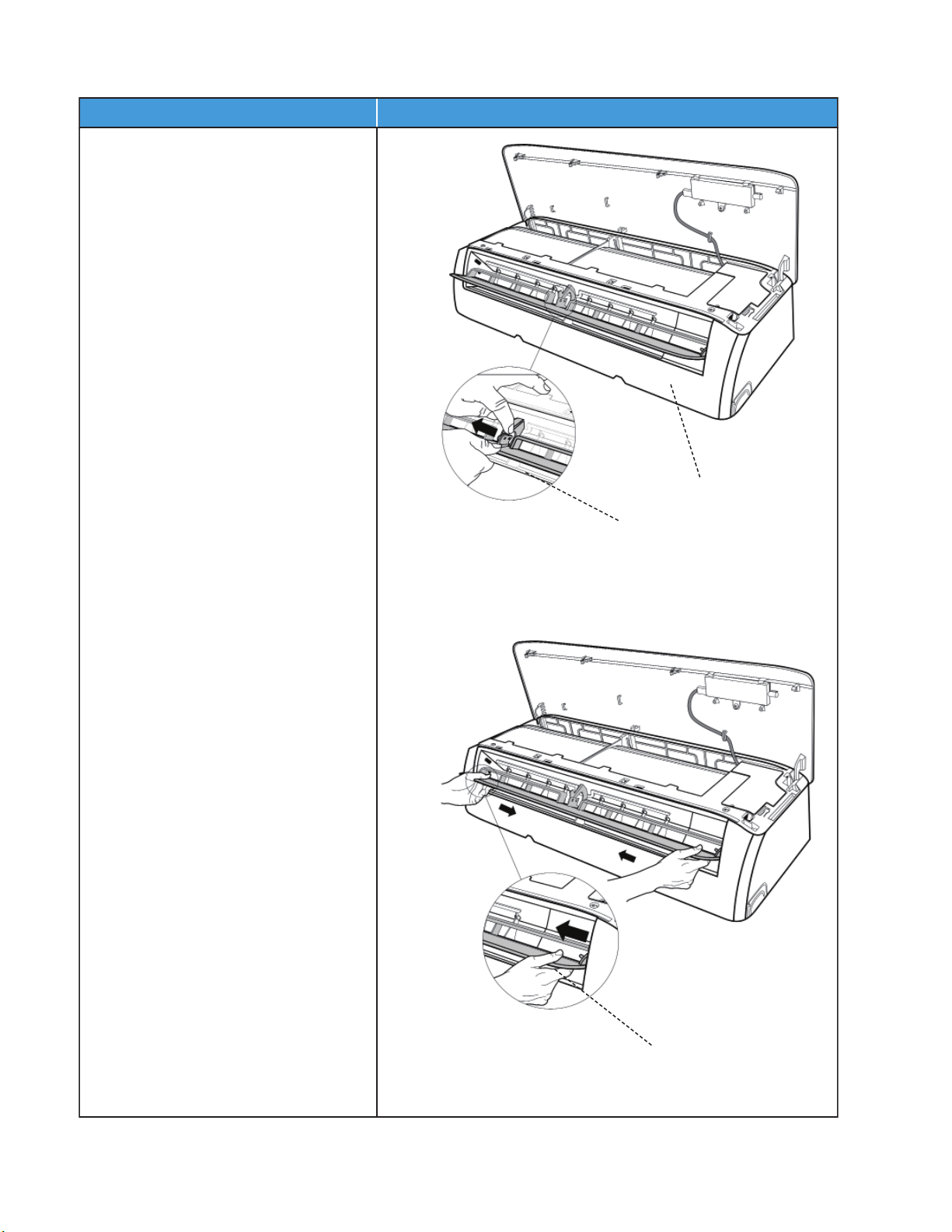
Indoor Unit Sizes 18K-24K (Front Panel) (continued)
3) Open the horizontal louver and push
the hook towards the left to open it.
4) Bend the horizontal louver lightly with
both hands to loosen the hooks, then
remove the horizontal louver.
Horizontal Louver
Hook
Hook
noitartsullIerudecorP
52 Specifications subject to change without notice. SM619PHA-03
Page 53
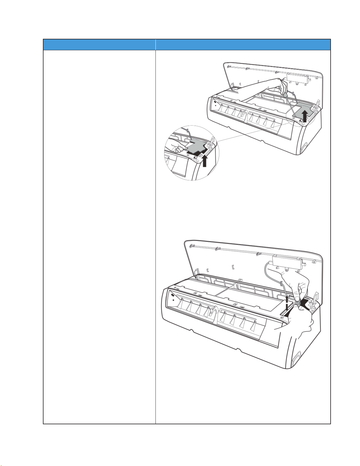
Indoor Unit Sizes 18K-24K (Front Panel) (continued)
noitartsullIerudecorP
5) Pry the electrical cover with a screwdriver
and rotate it towards the left, then
remove it.
6) Disconnect the connector on the display
board.
SM619PHA-03 Specifications subject to change without notice. 53
Page 54
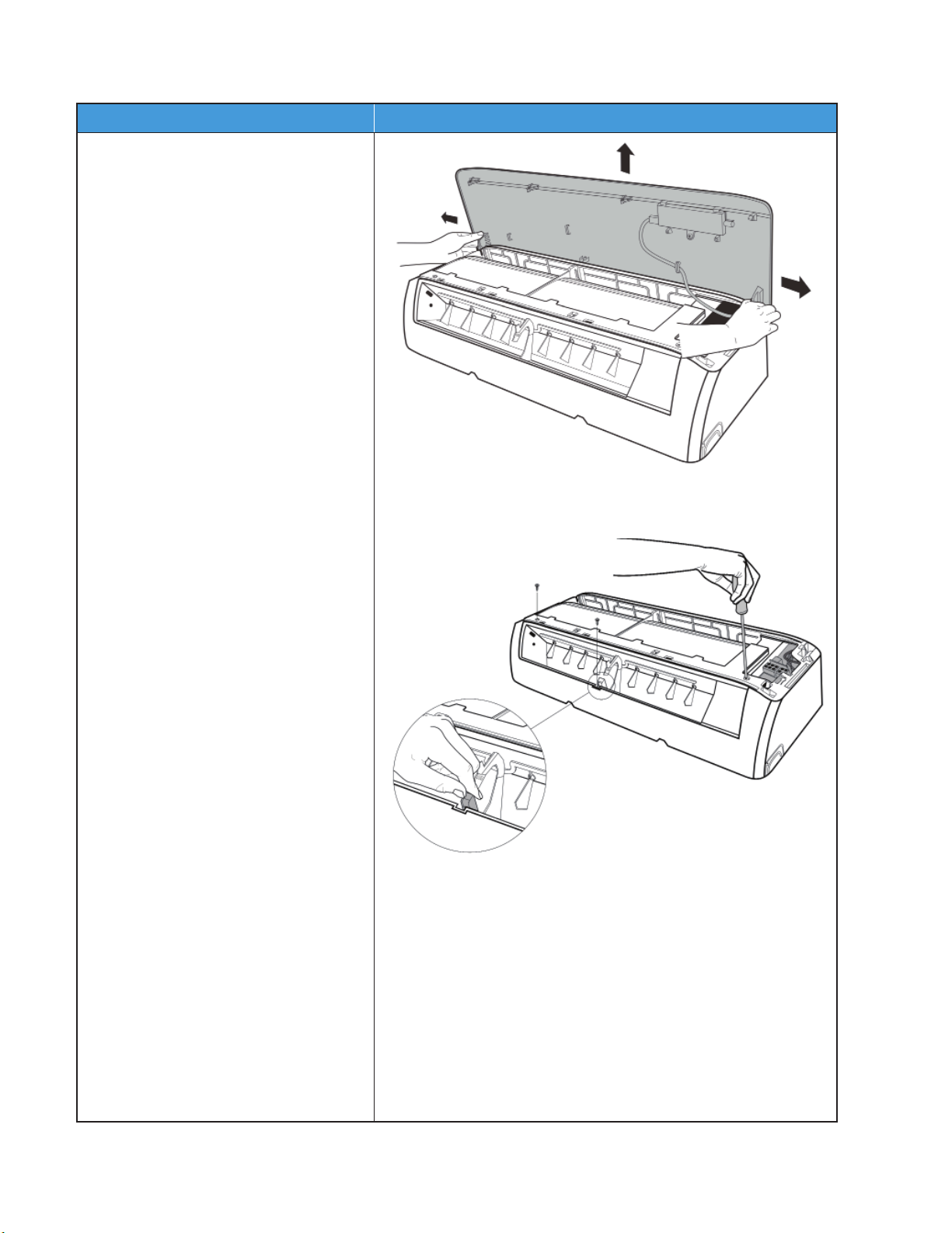
Indoor Unit Sizes 18K-24K (Front Panel) (continued)
noitartsullIerudecorP
7) Slide the front panel side to side to
release each axis.
8) Open the screw cap and then remove
the screws (3).
54 Specifications subject to change without notice. SM619PHA-03
Page 55
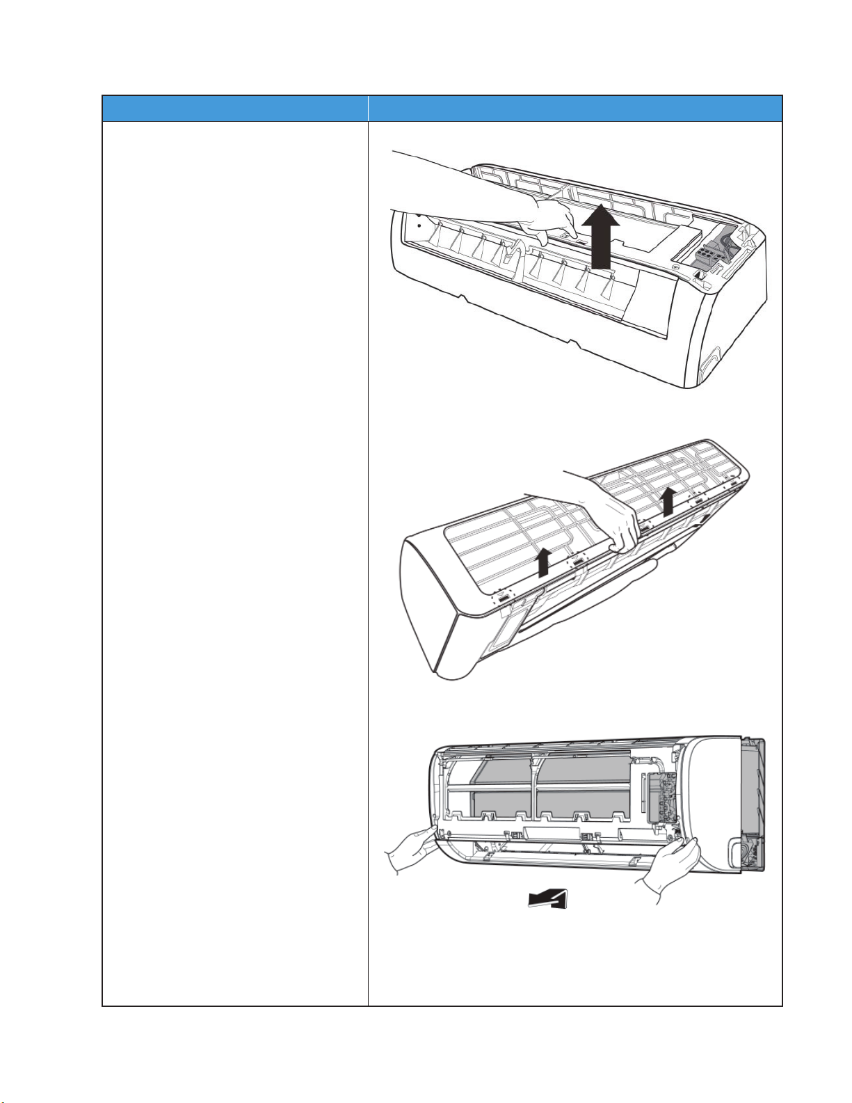
Indoor Unit Sizes 18K-24K (Front Panel) (continued)
noitartsullIerudecorP
9) Release the hooks by hand.
10) Release the 5 hooks in the back.
11) Pull out the panel frame, while pushing
the hook through the clearance between
the panel frame and the heat
exchanger.
SM619PHA-03 Specifications subject to change without notice. 55
Page 56
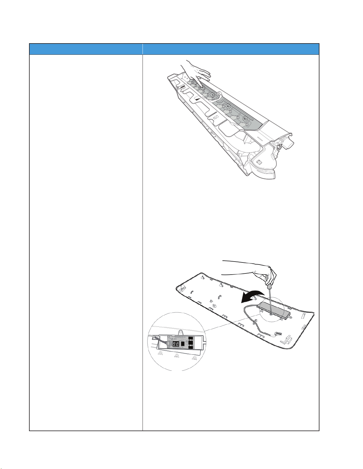
Indoor Unit Sizes 18K-24K (Front Panel) (continued)
noitartsullIerudecorP
12) Release the 5 hooks of the vertical
blades, then pull the vertical blades
toward the right and remove them.
13) Remove the display board’s screw (1).
14) Rotate the display board in the direction
shown in the picture (on the right).
56 Specifications subject to change without notice. SM619PHA-03
Page 57
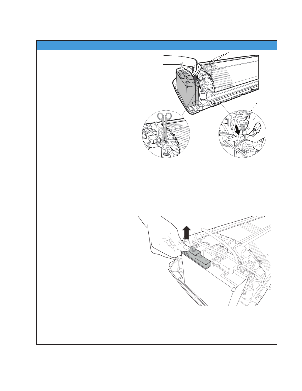
Indoor Unit Sizes 18K-24K (Electrical Parts) (Anti-static gloves must be worn)
noitartsullIerudecorP
1) Cut the ribbon with a shear, then pull
out the coil temperature sensor (T2).
2) Remove the fixing screw (1) on the
electronic control box and two screws
used for the ground connection.
3) An upward force is maintained until
the electronic control box cover is
removed.
Ribbon
T2 Sensor
Ground Screws
NOTE: Remove the front panel (refer to the front panel removal steps) before disassembling electrical parts.
SM619PHA-03 Specifications subject to change without notice. 57
Page 58
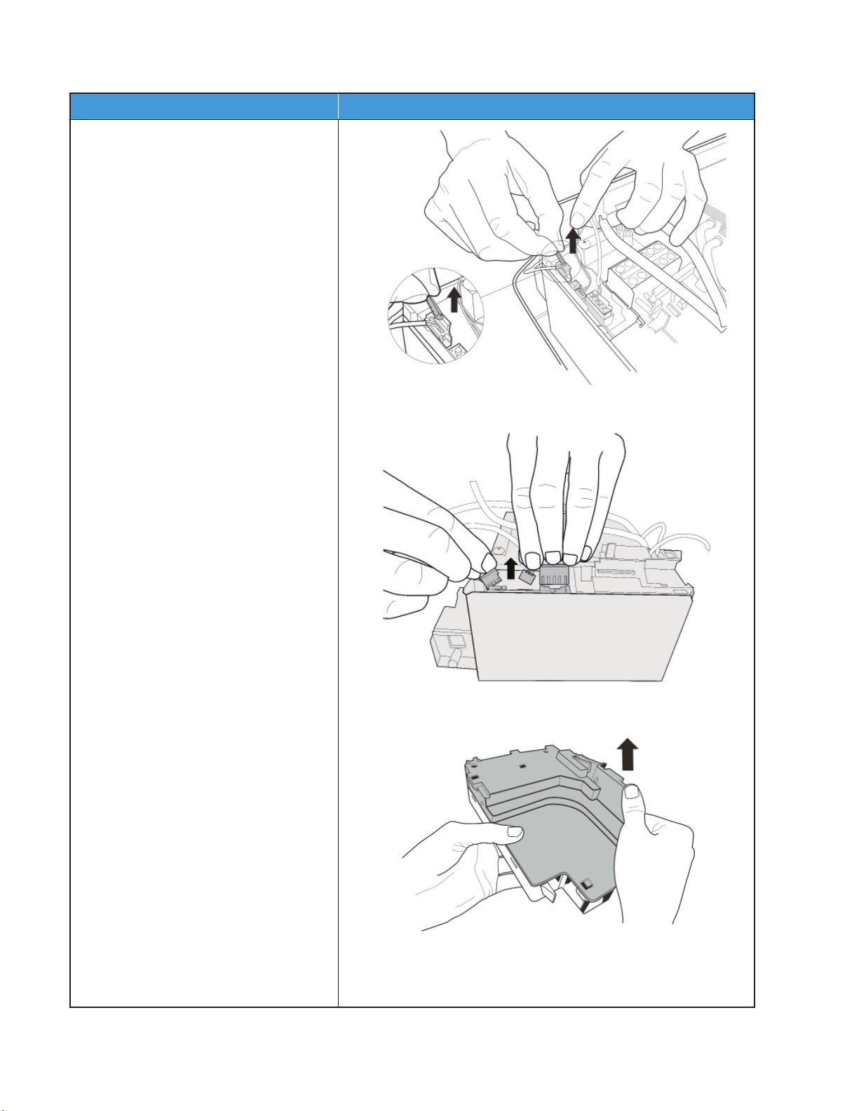
Indoor Unit Sizes 18K-24K (Electrical Parts) (Anti-static gloves must be worn) (continued)
noitartsullIerudecorP
4) Remove the fixed devices from the
connectors.
5) Disconnect the fan motor connectors,
the step motor and the T2 sensor.
6) Open the left side plate of the electronic
control box.
58 Specifications subject to change without notice. SM619PHA-03
Page 59
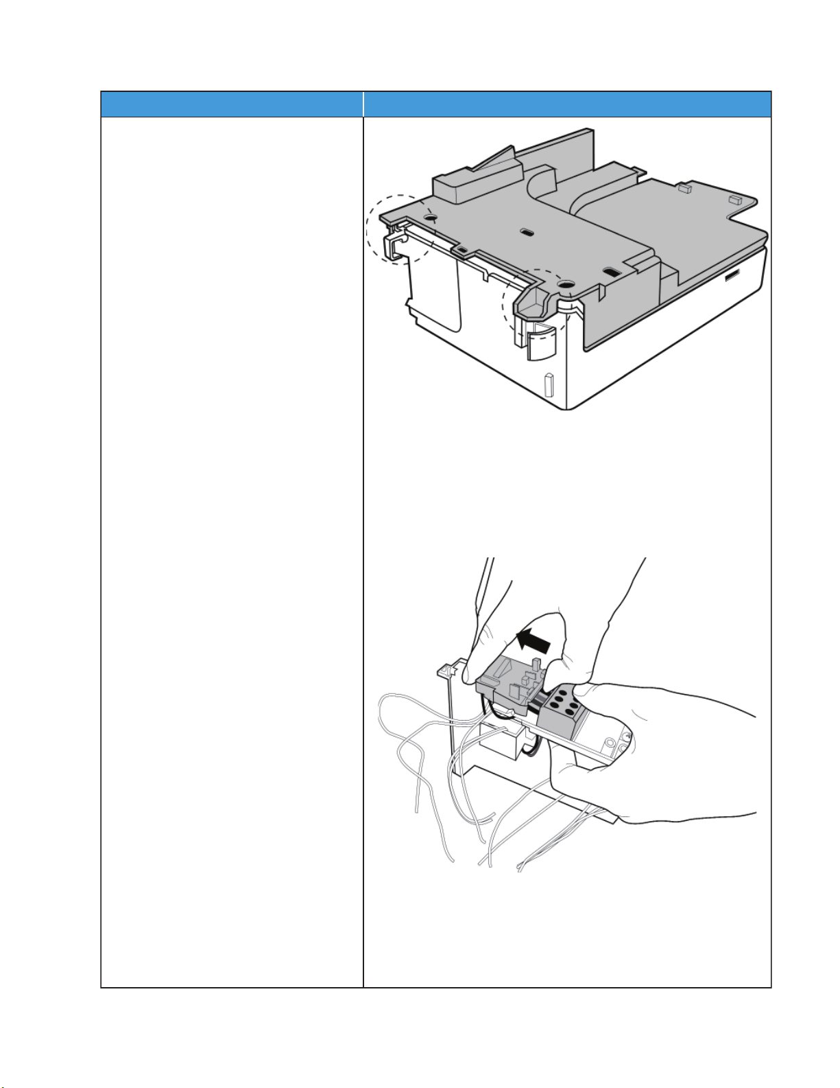
Indoor Unit Sizes 18K-24K (Electrical Parts) (Anti-static gloves must be worn) (continued)
noitartsullIerudecorP
7) Open the two clips on the front of the
electric box.
8) Open the upper cover plate of
the electronic control box.
SM619PHA-03 Specifications subject to change without notice. 59
Page 60
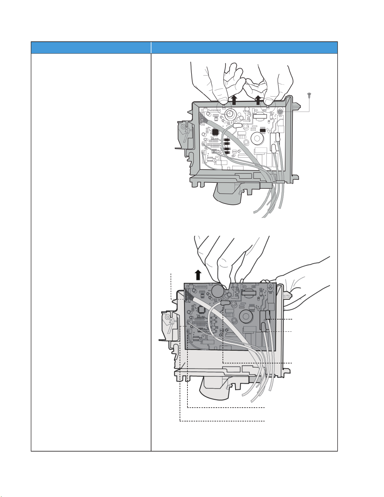
Indoor Unit Sizes 18K-24K (Electrical Parts) (Anti-static gloves must be worn) (continued)
noitartsullIerudecorP
9) Remove the screw (1) and open the 2
clips along the direction indicated in
the image on the right side.
10) Pull out the electrical main board
along the direction indicated in the
image on the right.
Display board
Terminal (1L)
Terminal (W)
Terminal (S)
Pipe Temperature Sensor
Room Temperature Sensor
60 Specifications subject to change without notice. SM619PHA-03
Page 61
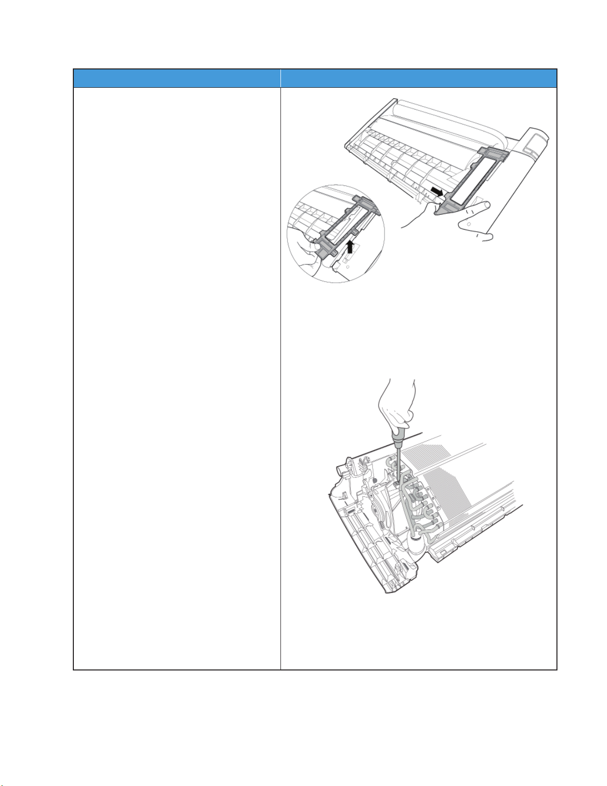
Indoor Unit Sizes 18K-24K (Evaporator)
noitartsullIerudecorP
1) Disassemble the pipe holder located at the
rear of the unit.
2) Remove the screw (1) on the evaporator
located at the fixed plate.
SM619PHA-03 Specifications subject to change without notice. 61
Page 62
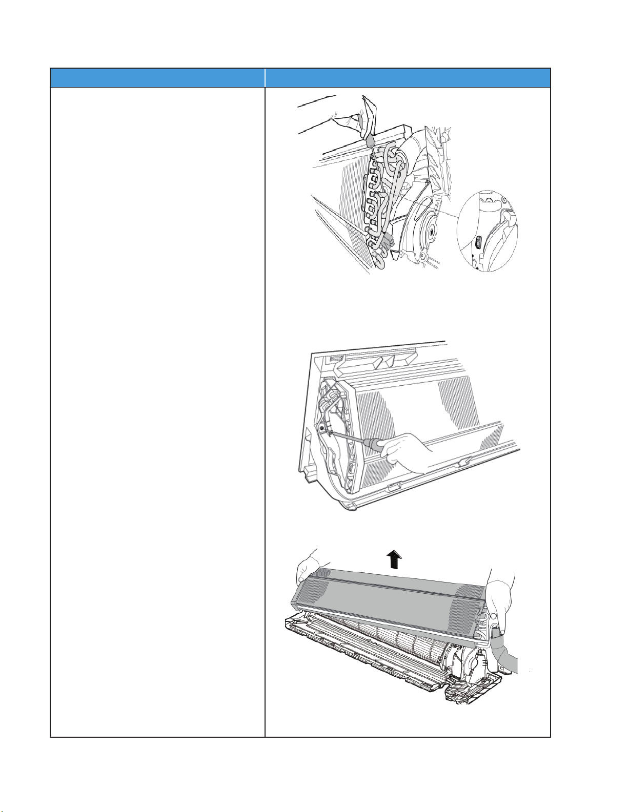
Indoor Unit Sizes 18K-24K (Evaporator) (continued)
noitartsullIerudecorP
3) Release the hook on the evaporator.
4) Remove the screw (1) on the evaporator
located at the fixed plate.
5) Remove the evaporator.
62 Specifications subject to change without notice. SM619PHA-03
Page 63
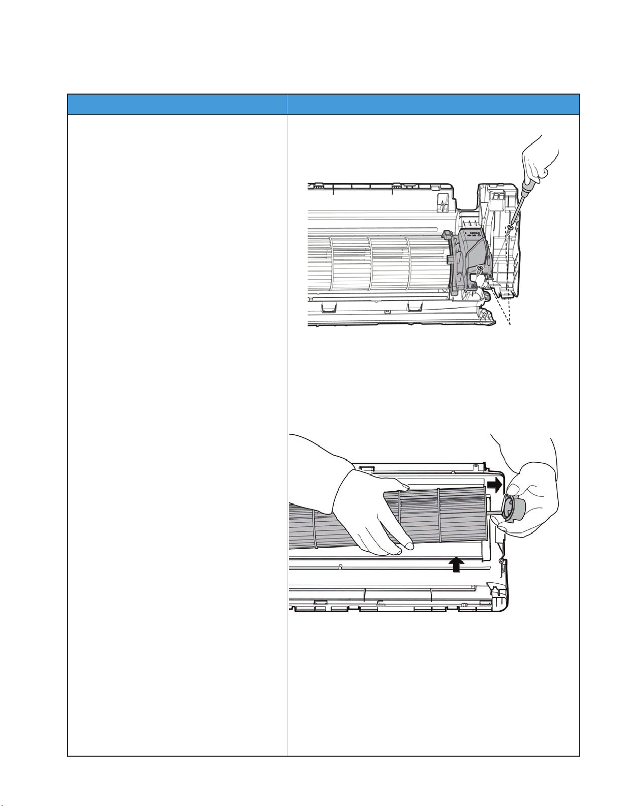
Indoor Unit Sizes 18K-24K (Fan Motor and Fan)
noitartsullIerudecorP
1) Remove the screws (2) and remove the
fixing board of the fan motor.
2) Remove the bearing sleeve.
Screws
NOTE: Remove the front panel, electrical parts and evaporator (refer to front panel, electrical parts, and evaporator
removal steps) before disassembling fan motor and fan.
SM619PHA-03 Specifications subject to change without notice. 63
Page 64
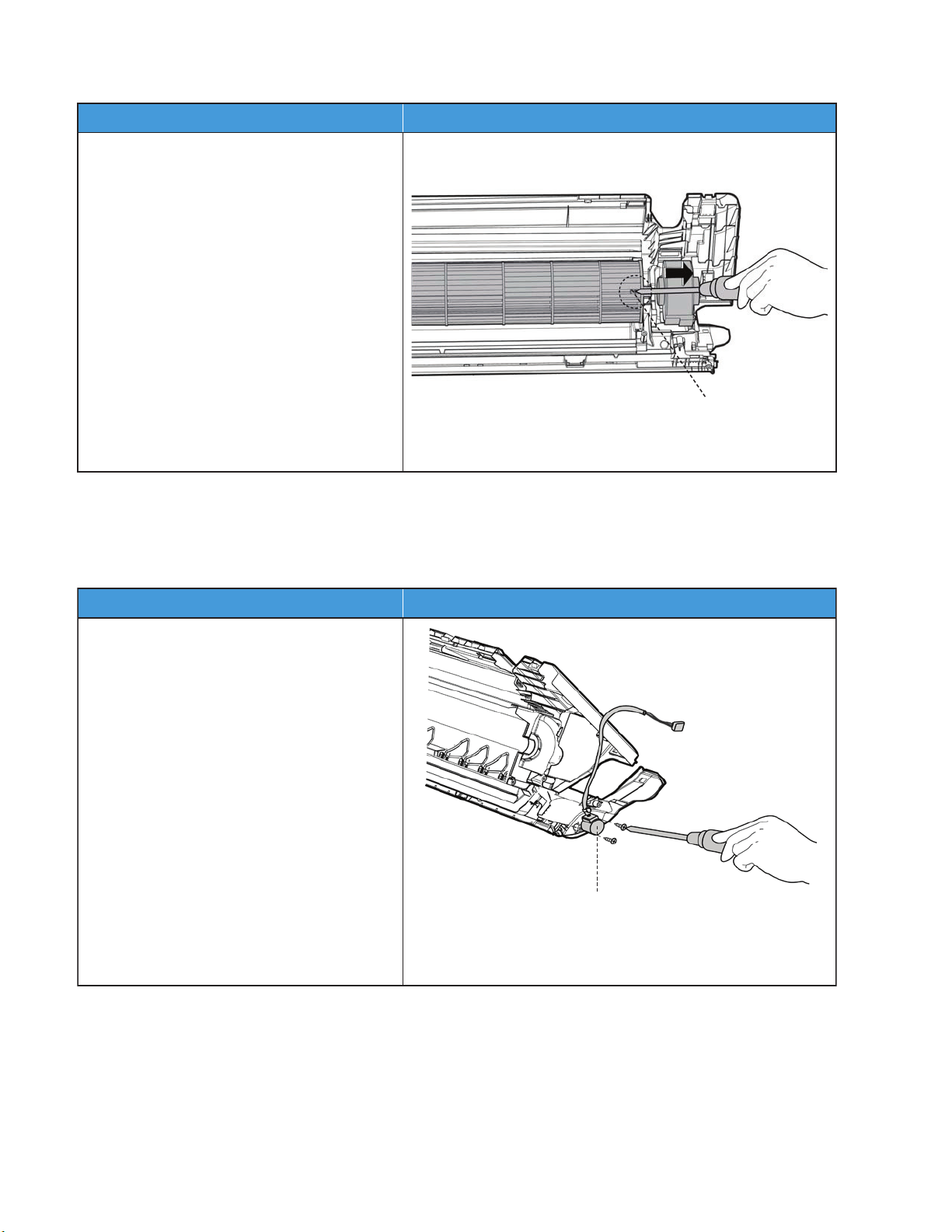
Indoor Unit Sizes 18K-24K (Fan Motor and Fan) (continued)
noitartsullIerudecorP
3) Remove the set screw.
4) Pull out the fan motor and fan assembly
from the side.
Fixing Screw
noitartsullIerudecorP
1) Remove the screws (2), then remove the
stepping motor.
Stepping Motor
Indoor Unit Sizes 18K-24K (Step Motor)
NOTE: Remove the front panel and electrical parts (refer to the front panel, electrical parts removal steps) before
disassembling the step motor.
64 Specifications subject to change without notice. SM619PHA-03
Page 65

APPENDICES
Appendix 1
Table 20 — Temperature Sensor Resistance Value Table for T1, T2, T3, T4 (C--K)
°C °F K OHM °C °F K OHM °C °F K OHM °C ° F K OHM
-20 -4 115.266 20 68 12.6431 60 140 2.35774 100 212 0.62973
-19 -2 108.146 21 70 12.0561 61 142 2.27249 101 214 0.61148
-18 0 101.517 22 72 11.5 62 144 2.19073 102 216 0.59386
-17 1 96.3423 23 73 10.9731 63 145 2.11241 103 217 0.57683
-16 3 89.5865 24 75 10.4736 64 147 2.03732 104 219 0.56038
-15 5 84.219 25 77 10 65 149 1.96532 105 221 0.54448
-14 7 79.311 26 79 9.55074 66 151 1.89627 106 223 0.52912
-13 9 74.536 27 81 9.12445 67 153 1.83003 107 225 0.51426
-12 10 70.1698 28 82 8.71983 68 154 1.76647 108 226 0.49989
-11 12 66.0898 29 84 8.33566 69 156 1.70547 109 228 0.486
-10 14 62.2756 30 86 7.97078 70 158 1.64691 110 230 0.47256
-9 16 58.7079 31 88 7.62411 71 160 1.59068 111 232 0.45957
-8 18 56.3694 32 90 7.29464 72 162 1.53668 112 234 0.44699
-7 19 52.2438 33 91 6.98142 73 163 1.48481 113 235 0.43482
-6 21 49.3161 34 93 6.68355 74 165 1.43498 114 237 0.42304
-5 23 46.5725 35 95 6.40021 75 167 1.38703 115 239 0.41164
-4 25 44 36 97 6.13059 76 169 1.34105 116 241 0.4006
-3 27 41.5878 37 99 5.87359 77 171 1.29078 117 243 0.38991
-2 28 39.8239 38 100 5.62961 78 172 1.25423 118 244 0.37956
-1 30 37.1988 39 102 5.39689 79 174 1.2133 119 246 0.36954
0 32 35.2024 40 104 5.17519 80 176 1.17393 120 248 0.35982
1 34 33.3269 41 106 4.96392 81 178 1.13604 121 250 0.35042
2 36 31.5635 42 108 4.76253 82 180 1.09958 122 252 0.3413
3 37 29.9058 43 109 4.5705 83 181 1.06448 123 253 0.33246
4 39 28.3459 44 111 4.38736 84 183 1.03069 124 255 0.3239
5 41 26.8778 45 113 4.21263 85 185 0.99815 125 257 0.31559
6 43 25.4954 46 115 4.04589 86 187 0.96681 126 259 0.30754
7 45 24.1932 47 117 3.88673 87 189 0.93662 127 261 0.29974
8 46 22.5662 48 118 3.73476 88 190 0.90753 128 262 0.29216
9 48 21.8094 49 120 3.58962 89 192 0.8795 129 264 0.28482
10 50 20.7184 50 122 3.45097 90 194 0.85248 130 266 0.2777
11 52 19.6891 51 124 3.31847 91 196 0.82643 131 268 0.27078
12 54 18.7177 52 126 3.19183 92 198 0.80132 132 270 0.26408
13 55 17.8005 53 127 3.07075 93 199 0.77709 133 271 0.25757
14 57 16.9341 54 129 2.95896 94 201 0.75373 134 273 0.25125
15 59 16.1156 55 131 2.84421 95 203 0.73119 135 275 0.24512
16 61 15.3418 56 133 2.73823 96 205 0.70944 136 277 0.23916
17 63 14.6181 57 135 2.63682 97 207 0.68844 137 279 0.23338
18 64 13.918 58 136 2.53973 98 208 0.66818 138 280 0.22776
19 66 13.2631 59 138 2.44677 99 210 0.64862 139 282 0.22231
SM619PHA-03 Specifications subject to change without notice. 65
Page 66

Appendix 2
Table 21 — Temperature Sensor Resistance Value Table for TP (T5)
° C ° F K OHM ° C ° F K OHM ° C ° F K OHM ° C ° F K OHM
-20 -4 542.7 20 68 68.66 60 140 13.59 100 212 3.702
-19 -2 511.9 21 70 65.62 61 142 13.11 101 214 3.595
-18 0 483 22 72 62.73 62 144 12.65 102 216 3.492
-17 1 455.9 23 73 59.98 63 145 12.21 103 217 3.392
-16 3 430.5 24 75 57.37 64 147 11.79 104 219 3.296
-15 5 406.7 25 77 54.89 65 149 11.38 105 221 3.203
-14 7 384.3 26 79 52.53 66 151 10.99 106 223 3.113
-13 9 363.3 27 81 50.28 67 153 10.61 107 225 3.025
-12 10 343.6 28 82 48.14 68 154 10.25 108 226 2.941
-11 12 325.1 29 84 46.11 69 156 9.902 109 228 2.86
-10 14 307.7 30 86 44.17 70 158 9.569 110 230 2.781
-9 16 291.3 31 88 42.33 71 160 9.248 111 232 2.704
-8 18 275.9 32 90 40.57 72 162 8.94 112 234 2.63
-7 19 261.4 33 91 38.89 73 163 8.643 113 235 2.559
-6 21 247.8 34 93 37.3 74 165 8.358 114 237 2.489
-5 23 234.9 35 95 35.78 75 167 8.084 115 239 2.422
-4 25 222.8 36 97 34.32 76 169 7.82 116 241 2.357
-3 27 211.4 37 99 32.94 77 171 7.566 117 243 2.294
-2 28 200.7 38 100 31.62 78 172 7.321 118 244 2.233
-1 30 190.5 39 102 30.36 79 174 7.086 119 246 2.174
0 32 180.9 40 104 29.15 80 176 6.859 120 248 2.117
1 34 171.9 41 106 28 81 178 6.641 121 250 2.061
2 36 163.3 42 108 26.9 82 180 6.43 122 252 2.007
3 37 155.2 43 109 25.86 83 181 6.228 123 253 1.955
4 39 147.6 44 111 24.85 84 183 6.033 124 255 1.905
5 41 140.4 45 113 23.89 85 185 5.844 125 257 1.856
6 43 133.5 46 115 22.89 86 187 5.663 126 259 1.808
7 45 127.1 47 117 22.1 87 189 5.488 127 261 1.762
8 46 121 48 118 21.26 88 190 5.32 128 262 1.717
9 48 115.2 49 120 20.46 89 192 5.157 129 264 1.674
10 50 109.8 50 122 19.69 90 194 5 130 266 1.632
11
12 54 99.69 52 126 18.26 92 198 4.703
13 55 95.05 53 127 17.58 93 199 4.562
14 57 90.66 54 129 16.94 94 201 4.426
15 59 86.49 55 131 16.32 95 203 4.294
16 61 82.54 56 133 15.73 96 205 4.167
17 63 78.79 57 135 15.16 97 207 4.045
18 64 75.24 58 136 14.62 98 208 3.927
19 66 71.86 59 138 14.09 99 210 3.812
52 104.6 51 124 18.96 91 196 4.849
66 Specifications subject to change without notice. SM619PHA-03
Page 67

Appendix 3
Table 22 —
° C ° F ° C ° F ° C ° F ° C ° F ° C ° F
-5 23 21 69.8 51 123.8 82 179.6 113 235.4
-4 24.8 22 71.6 52 125.6 83 181.4 114 237.2
-3 26.6 23 73.4 53 127.4 84 183.2 115 239
-2 28.4 24 75.2 54 129.2 85 185 116 240.8
-1 30.2 25 77 55 131 86 186.8 117 242.6
0 32 25.5 77.9 56 132.8 87 188.6 118 244.4
0.5 32.9 26 78.8 57 134.6 88 190.4 119 246.2
1 33.8 27 80.6 58 136.4 89 192.2 120 248
1.5 34.7 28 82.4 59 138.2 90 194 121 249.8
2 35.6 29 84.2 60 140 91 195.8 122 251.6
2.5 36.5 30 86 61 141.8 92 197.6 123 253.4
3 37.4 31 87.8 62 143.6 93 199.4 124 255.2
3.5 38.3 32 89.6 63 145.4 94 201.2 125 257
4 39.2 33 91.4 64 147.2 95 203 126 258.8
4.5 40.1 34 93.2 65 149 96 204.8 127 260.6
5 41 35 95 66 150.8 97 206.6 128 262.4
6 42.8 36 96.8 67 152.6 98 208.4 129 264.2
7 44.6 37 98.6 68 154.4 99 210.2 130 266
8 46.4 38 100.4 69 156.2 100 212 131 267.8
9 48.2 39 102.2 70 158 101 213.8 132 269.6
10 50 40 104 71 159.8 102 215.6 133 271.4
11 51.8 41 105.8 72 161.6 103 217.4 134 273.2
12 53.6 42 107.6 73 163.4 104 219.2 135 275
13 55.4 43 109.4 74 165.2 105 221 136 276.8
14 57.2 44 111.2 75 167 106 222.8 137 278.6
15 59 45 113 76 168.8 107 224.6 138 280.4
16 60.8 46 114.8 77 170.6 108 226.4 139 282.2
17 62.6 47 116.6 78 172.4 109 228.2 140 284
18 64.4 48 118.4 79 174.2 110 230 141 285.8
19 66.2 49 120.2 80 176 111 231.8 142 287.6
20 68 50 122 81 177.8 112 233.6 143 289.4
Celsius to Fahrenheit
SM619PHA-03 Specifications subject to change without notice. 67
Page 68

2019 Bryant Heating & Cooling Systems D3300 Riverwood Parkway Atlanta GA, 30339 Edition Date: 04/19 Catalog No. SM619PHA-03
Manufacturer reserves the right to discontinue, or change at any time, specifications or designs without notice and without incurring obligations. Replaces: SM619PHA-02
 Loading...