

Page 1
NOTE: Read
the entire
instruction manual
before starting the
installation.
TABLE OF CONTENTS
SAFETY CONSIDERATIONS.....................................................1
INTRODUCTION..........................................................................2
RECEIVING AND INSTALLATION..........................................2
ICM FIOP PRE-START-UP..........................................................2
Electrical Connections..............................................................2
Control
Voltage Connections..............................................2
Standard
Connection............................................................2
Easy Select™—583B
..........................................................2
583B Sequence of Operation..............................................4
Easy Select™—683B
..........................................................5
683B
Sequence of Operation..............................................7
Easy Select™—702B & 602B............................................7
702B & 602B Sequence Of Operation...............................9
ICM FIOP START-UP................................................................10
583B Start-Up (ICM FIOP)....................................................10
683B Start-Up (ICM FIOP)....................................................10
702B:
Start-Up (ICM
FIOP) ..................................................11
602B:
Start-Up (ICM FIOP) ..................................................11
ELECTRICAL DATA & SCHEMATICS—ICM FIOP.............12
Physical Data & Electrical Schematics..................................12
Tables For
System Set-Up......................................................12
CARE AND MAINTENANCE...................................................12
TROUBLESHOOTING ...............................................................13
START-UP CHECKLIST............................................................13
NOTE TO INSTALLER — READ THESE INSTRUCTIONS
CAREFULLY AND COMPLETELY before installing this unit.
Also, make
sure the Owner’s Manual and Service Instructions are
left with the unit after installation.
SAFETY CONSIDERATIONS
Installation and servicing of air-conditioning equipment can be
hazardous due to system pressure and electrical components. Only
trained and qualified personnel should install, repair, or service
air-conditioning equipment.
Untrained personnel can perform basic maintenance functions of
cleaning coils and filters. All other operations should be performed
by trained service personnel. When working on air-conditioning
equipment, observe precautions in the
literature, tags, and labels
attached to the unit, and other safety precautions that may apply.
Follow all safety codes. Wear safety glasses and work gloves. Use
quenching cloth for unbrazing operations. Have fire extinguisher
available for all brazing operations.
WARNING: Improper installation, adjustment, alteration, service, maintenance, or use can cause explosion,
fire, electric shock, or other occurrences, which could
cause serious injury
or death or
damage your
property.
Consult a qualified installer or service agency for information or assistance. The qualified installer or agency
must use only factory-authorized kits or accessories when
modifying this product.
Recognize safety information. This is the safety-alert symbol .
When you see this symbol on the product or in instructions or
manuals, be alert to the potential for personal injury.
Understand the signal words — DANGER, WARNING, CAUTION, and NOTE. Danger identifies the most serious hazards,
which will result in severe personal injury or death. Warning
indicates a condition that could cause serious personal injury or
death. Caution is used to
identify unsafe practices, which
would
result in minor personal injury or product and property damage.
NOTE is used to highlight suggestions which will result in
enhanced installation, reliability, or operation.
The power supply (volts, phase, and hertz) must correspond to that
specified on unit rating plate.
The electrical supply provided by the utility must be sufficient to
handle load imposed by this unit. Electrical supply must match the
voltage requirements listed on unit rating plate.
This installation must conform with local building codes and with
NEC (National Electrical Code). Refer to provincial and local
plumbing or waste water codes and other applicable local codes.
Approved for outdoor installation on wood flooring or on class A,
B or C roof covering materials.
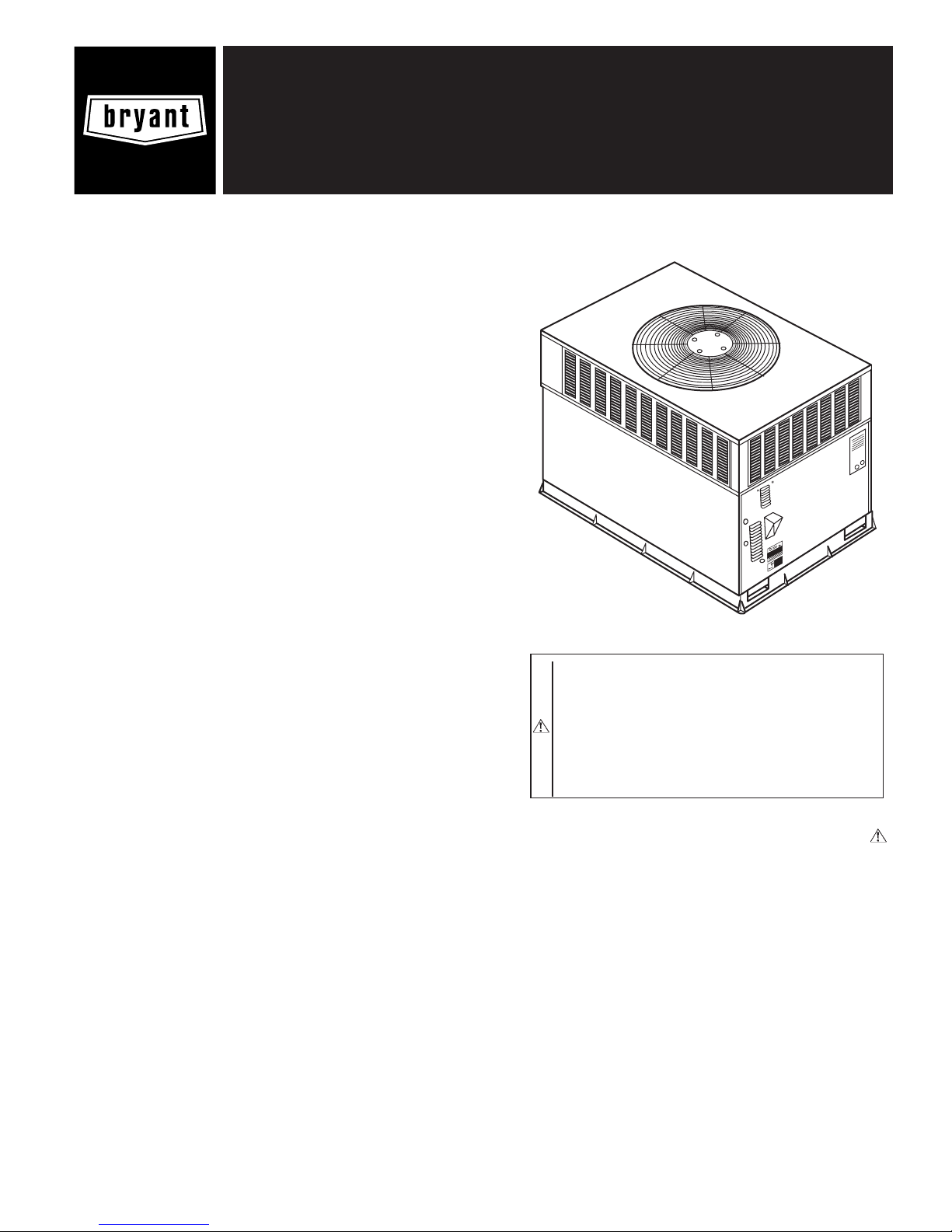
Fig. 1—Puron® Unit (583B Shown)
C99087
ICM FIOP
INSTALLATION INSTRUCTIONS
installation, start-up,
—1—
and operating instructions
583B
683B
602B
702B
Cancels:II583B-24-2II583B-24-3
11-01
Page 2
WARNING: Before performing service or maintenance
operations on system, turn off main power to unit and
install lock-out tag. Turn off accessory heater power
switch if applicable. Electrical shock could cause severe
injury or death.
CAUTION: Puron® (R-410A) systems operate at higher
pressures than standard R-22 systems. Do not use R-22
service equipment or components on Puron® (R-410A)
equipment. Ensure service equipment is rated for Puron®
(R-410A)
INTRODUCTION
NOTE: The minimum outdoor cooling operating temperature for
units using this ICM motor option is 55°F. To operate in cooling
at lower ambients the Motor Master™ II low ambient kit is
required.
These instructions cover the installation of a Bryant Small Packaged Product with ICM motor-factory installed option (FIOP).
This option can be selected as a FIOP on gas heating/electric
cooling (583B), dual fuel–electric heat pump with gas heat
back-up (683B), electric cooling (702B) or electric heat pump
(602B) units with Puron®.
RECEIVING AND INSTALLATION
Refer to unit Installation Instructions.
ICM FIOP PRE-START-UP
I. ELECTRICAL CONNECTIONS
A. Control Voltage Connections
NOTE: Do not use any type of power-stealing thermostat, with-
out connecting the C (Common) terminal. Failure to follow this
note could result in unit control problems.
Use no. 18 American Wire Gage (AWG) color-coded, insulated
(35 C minimum) wires to make the control voltage connections
between the thermostat and the unit. If the thermostat is located
more than 100 ft from the unit (as measured along the control
voltage wires), use no. 16 AWG color-coded, insulated (35 C
minimum) wires.
B. Standard Connection
Remove knockout hole located in the heat section panel adjacent to
the service access panel (See unit installation package). Remove
the rubber grommet from the installer’s packet (included with unit)
and install grommet in the knockout opening. Provide a drip loop
before running wire through panel. Run the low-voltage leads from
the thermostat, through the inlet hole, and into unit low-voltage
splice box. Locate 18-gage wires leaving control box. These
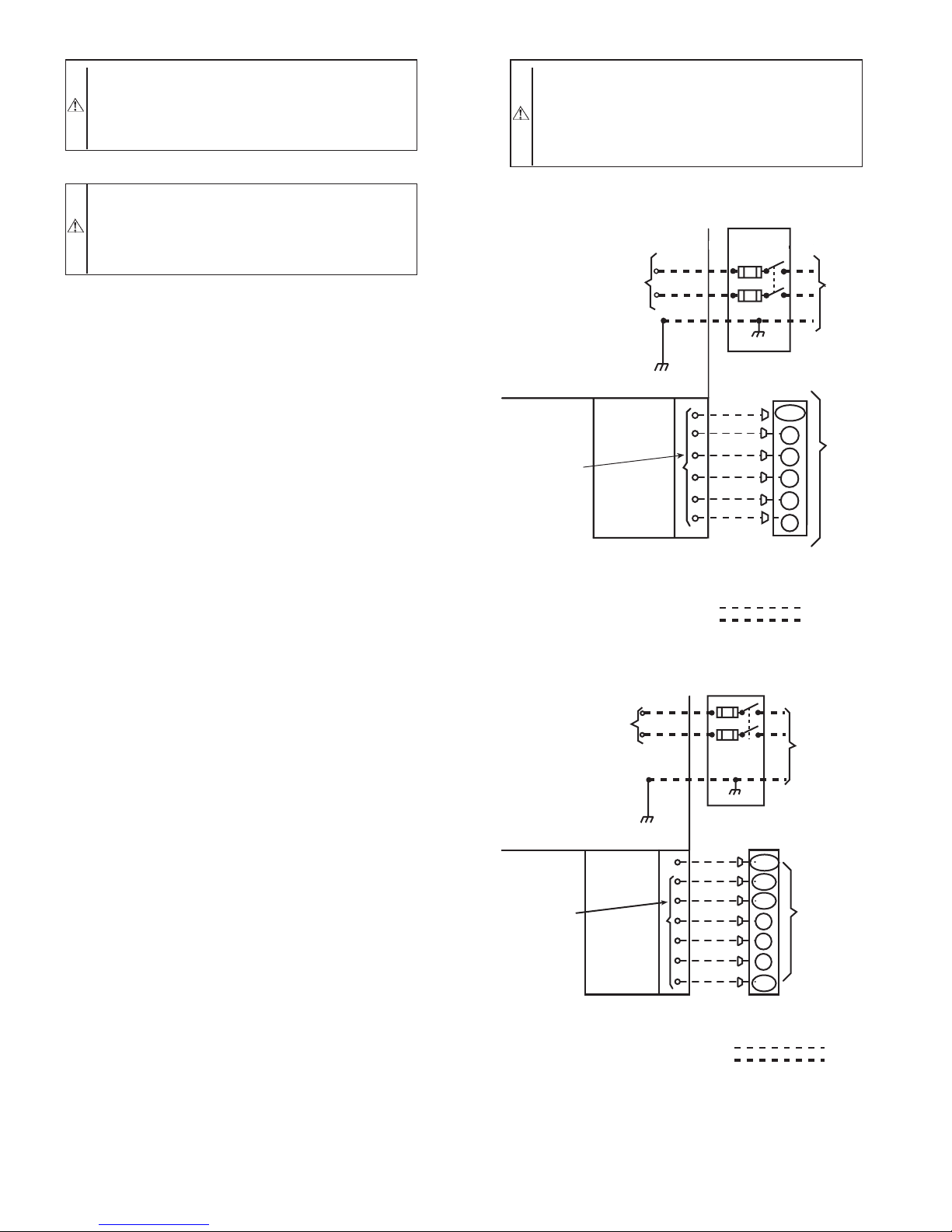
low-voltage connection leads can be identified by colors (See Fig.
2, 3, 4 or 5). Ensure the leads are long enough to be routed into the
low-voltage splice box (located below right side of control box).
Route leads through hole in bottom of control box and make
low-voltage connections (See Fig. 2, 3, 4 or 5). Secure all cut
wires, so that they do not interfere with operation of unit.
SPECIAL PROCEDURES FOR 208–V OPERATION
WARNING: Make sure that the power supply to the unit
is switched OFF before making any wiring changes. With
disconnect switch open, move yellow wire from transformer (3/16 in.) terminal marked 230 to terminal marked
200. This retaps transformer to primary voltage of 208-v.
Electrical shock could cause serious injury or death.
C. Easy Select™—583B
EASY SELECT™ CONFIGURATION TAPS FOR 583B
Easy Select™ taps are used by the installer to configure a system.
The ICM motor uses the selected taps to modify its operation to a
Fig. 2—583B High- and Control-Voltage
Connections
C01026
POWER
SUPPLY
FIELD-SUPPLIED
FUSED DISCONNECT
HIGH VOLT AGE
POWER LEADS
(SEE UNIT WIRING
LABEL)
GND
CONTROL BOX
SPLICE BOX
LOW-VOLTAGE
POWER LEADS
(SEE UNIT
WIRING LABEL)
YEL(Y)
GRN(G)
RED(R)
BRN(C)
THERMOSTAT
(TYPICAL)
LEGEND
Field Control-Voltage Wiring
Field High-Voltage Wiring
BLK(DH)
DHUM
Y
G
R
C
W1
WHI(W1)
Fig. 3—683B High- and Control-Voltage
Connections
C01107
POWER
SUPPLY
FIELD-SUPPLIED
FUSED DISCONNECT
HIGH VOLTA GE
POWER LEADS
(SEE UNIT WIRING
LABEL)
GND
CONTROL BOX
SPLICE BOX
LOW-VOLTAGE
POWER LEADS
(SEE UNIT
WIRING LABEL)
THERMOSTAT
(THERMIDISTAT ™ )
G
R
C
YEL(Y)
GRN(G)
RED(R)
BRN(C)
ORN(O)
W/W1
WHT(W1)
DHUM
BLK (DH)
FIELD CONTROL - VOLTAGE WIRING
FIELD HIGH - VOLTAGE WIRING
Y/Y2
O/W2
—2—
Page 3
pre-programmed table of airflows.
The unit must be configured to operate properly with system
components with which it is installed. To successfully configure a
basic system (see information printed on circuit board label located
next to select pins), move the 6 select wires to the pins which
match the components used (See Fig. 8).
a. GAS HEAT/CFM—SELECT GAS HEAT INPUT SIZE
Factory selected gas heat size should correspond to unit label.
b. AC/HP SIZE—SELECT SYSTEM SIZE INSTALLED
Factory selected air conditioner size should correspond to
capacity of unit installed. Installer should verify air conditioner
size to ensure that airflow delivered falls within proper range
for the size unit installed. This applies to all operational modes.
c. SYSTEM TYPE—SELECT SYSTEM TYPE INSTALLED
Factory selected on 583B for AC-Air conditioner.
For Gas Heat/Electric Cool Unit–AC must be selected.
d. AC/HP CFM ADJUST—SELECT NOMINAL, LOW, OR
HIGH AIRFLOW
The AC/HP CFM Adjust select is factory set to the High-HI
(NOM for 060) tap. The CFM Adjust selections NOM/LO will
regulate airflow supplied for all operational modes, except
non-heat pump heating modes. HI provides 15 percent airflow
over nominal unit size selected and LO provides 10 percent
airflow below nominal unit size selected. Adjust selection
options are provided to adjust airflow supplied to meet individual installation needs for such things as noise, comfort, and
humidity removal (See Fig. 8, D as indicated).
e. ON/OFF DELAY—SELECT DESIRED
TIME DELAY PROFILE
Four motor operation delay profiles are provided to customize
and enhance system operation (See Fig. 8, E as indicated).
Selection options are:
(1.) The standard 90 sec off delay (Factory Setting) at 100
percent airflow in cooling mode. In heating mode, IGC
will control 45 sec on delay with no airflow and 45 sec off
delay.
(2.) A 30 sec cooling delay with no airflow/ 90 sec off delay at
100 percent airflow profile is used when it is desirable to
allow system coils time to cool-down in conjunction with
the airflow in heating mode.
(3.) A no delay option used for servicing unit or when a
thermostat is utilized to perform delay functions in cooling
mode. In heating mode IGC will control 45 sec on delay
with no airflow and 45 sec off delay.
(4.) Not recommended for 583B
f. CONTINUOUS FAN—SELECT DESIRED FAN SPEED
WHEN THERMOSTAT IS SET ON CONTINUOUS FAN
(1.) LO speed—Factory setting, 50 percent cooling mode
airflow.
(2.) MED speed—Move connector to MED, 65 percent cooling
mode airflow.
(3.) HI speed—Move connector to HI, 100 percent cooling
mode airflow (See Fig. 8, F as indicated).
g. LOW-VOLTAGE CIRCUIT FUSING AND REFERENCE
The low-voltage circuit is fused by a board-mounted 5–amp
automotive fuse placed in series with the transformer SEC2 and
the R circuit. The C circuit of the transformer is referenced to
chassis ground through a printed circuit run at SEC1 connected
to metal standoff marked with ground symbol.
h. BASIC UNIT CONFIGURATION
The following basic configuration of the indoor motor will
provide ARI rated performance of the 583B. This BASIC
CONFIGURATION should be used when the rated ARI performance is required, or if system enhancements such as super
dehumidify are not needed.
(1.) HEAT-Factory selected to match heat input size.
(2.) AC/HP Size-Factory selected to match system size, please
verify.
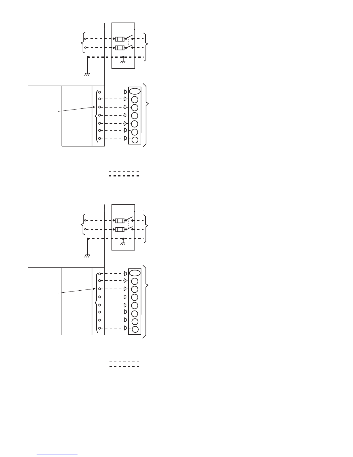
Fig. 4—702B High- and Control-Voltage
Connections
C01027
POWER
SUPPLY
FIELD-SUPPLIED
FUSED DISCONNECT
HIGH VOLT AGE
POWER LEADS
(SEE UNIT WIRING
LABEL)
GND
CONTROL BOX
SPLICE BOX
LOW-VOLTAGE
POWER LEADS
(SEE UNIT
WIRING LABEL)
YEL(Y)
GRN(G)
RED(R)
BRN(C)
THERMOSTAT
(TYPICAL)
LEGEND
Field Control-Voltage Wiring
Field High-Voltage Wiring
BLK(DH)
DHUM
Y
G
R
C
W1
WHI(W1)
GRA(W2)
W2
Fig. 5—602B High- and Control-Voltage
Connections
C01028
POWER
SUPPLY
FIELD-SUPPLIED
FUSED DISCONNECT
HIGH VOLT AGE
POWER LEADS
(SEE UNIT WIRING
LABEL)
GND
CONTROL BOX
SPLICE BOX
LOW-VOLTAGE
POWER LEADS
(SEE UNIT
WIRING LABEL)
YEL(Y)
GRN(G)
RED(R)
BRN(C)
THERMOSTAT
(TYPICAL)
LEGEND
Field Control-Voltage Wiring
Field High-Voltage Wiring
BLK(DH)
DHUM
Y
G
R
C
W1
WHI(W1)
GRA(W2)
W2
ORN(0)
O
—3—
Page 4

(3.) SYSTEM TYPE-Factory selected on 583B system AC-
AIR CONDITIONER.
(4.) AC/HP CFM ADJUST-Select HIGH for 042 & 048, NOM
for 036 & 060, and LO for 024 & 030..
(5.) ON/OFF DELAY-Factory selected 0/90 profile.
(6.) CONTINUOUS FAN-Select desired fan speed when ther-
mostat is set to continuous fan.
i. COMFORT OPTIONS—SUPER DEHUMIDIFY (See Quick
Reference Guide)
The Super Dehumidify option is possible when this unit is
installed with a field supplied Thermidistat™ control (SuperDehumidify does not require an outdoor temperature sensor).
The following configuration is recommended for maximum
cooling/dehumidifying comfort. This configuration will improve the comfort provided by the air conditioning system if
more humidity removal is desired. While providing this improved comfort, the system will operate efficiently, but not at
the published ARI SEER efficiency. During cool-to-dehumidify
call, it provides maximum dehumidification by reducing airflow
to a minimum. The actual super dehumidify command from
Thermidistat™ control to the indoor unit is a “Y” signal without
a “G” signal in addition to dehumidify signal. The indoor unit
responds to this combination by reducing the airflow to a
minimum. All other characteristics of cool to dehumidify are the
same.
The following system configuration is recommended for maximum cooling/dehumidifying comfort (See Fig. 8).
(1.) HEAT-Factory selected to match gas heat size of unit
installed.
(2.) AC/HP Size-Factory selected to match system size, please
verify.
(3.) SYSTEM TYPE-Factory selected on 583B system AC-
AIR CONDITIONER.
(4.) AC/HP CFM ADJUST-Select NOM (Lo for 060).
(5.) ON/OFF DELAY-Select ENH profile.
(6.) CONTINUOUS FAN-Select desired fan speed when ther-
mostat is set to continuous fan.
(7.) DEHUMIDIFY MODE-Remove J1 jumper to activate.
NOTE: J1 jumper should only be removed when a Thermidistat™, humidistat or capable zoning control is installed.
(8.) LOW VOLTAGE CONNECTIONS-Make connections as
shown in ELECTRICAL CONNECTIONS section.
(9.) CONFIGURE THERMIDISTAT™-Follow Thermidis-
tat™ (or capable zoning system) installation instructions
for Super Dehumidify operation.
ACCESSORY INSTALLATION
a. AUXILIARY TERMINALS
The AUX and HUM terminals on the Easy Select™ Board are
tied directly to the G terminal, and provide a 24-v. signal
whenever the G terminal is energized (See Fig. 6). During
Super dehumidify mode, the G signal is not present and the
auxiliary terminals are not energized. If the installation includes
the use of this operating mode, do not use these terminals to
control accessories. See Electronic Air Cleaner and Humidifier
sections for further information.
b. ELECTRONIC AIR CLEANER CONNECTIONS
The AUX1 and AUX2 terminals are not always energized
during blower operations, as described above. When using an
electronic air cleaner with the unit, use Airflow Sensor P/N.
KEAAC0101AAA. The airflow sensor turns on electronic air
cleaner when the blower is operating.
c. HUMIDIFIER/HUMIDISTAT CONNECTIONS
Easy Select™ Board terminals HUM1 and HUM2 are provided
for direct connection to the low-voltage control of a humidifier
through a standard humidistat (See Fig. 6). These terminals are
energized with 24-v. when G thermostat signal is present (See
Fig. 6 & 7). Alternately, the 24-v. signal may be sourced from
the W and C on the 9 pin connector. When using a Thermidistat™ Control, Zone Perfect Plus or Comfort Zone II, the 24-v.
signal may be sourced directly from the Thermidistat™ HUM
terminal (See Fig. 6,7&8).
d. DEHUMIDIFY CAPABILITY WITH STANDARD
HUMIDISTAT CONNECTION
Latent capacities for this unit are better than average systems. If
increased latent capacity is an application requirement, the ICM
board provides connection terminals for use of a standard
humidistat. The unit will detect the humidistat contacts opening
on increasing humidity and reduce its airflow to approximately
80 percent of nominal cooling mode airflow. This reduction
will increase the system latent capacity until the humidity falls
to a level which causes the humidistat to close its contacts.
When the contacts close, the airflow will return to 100 percent
of selected cooling airflow. To activate this mode, remove
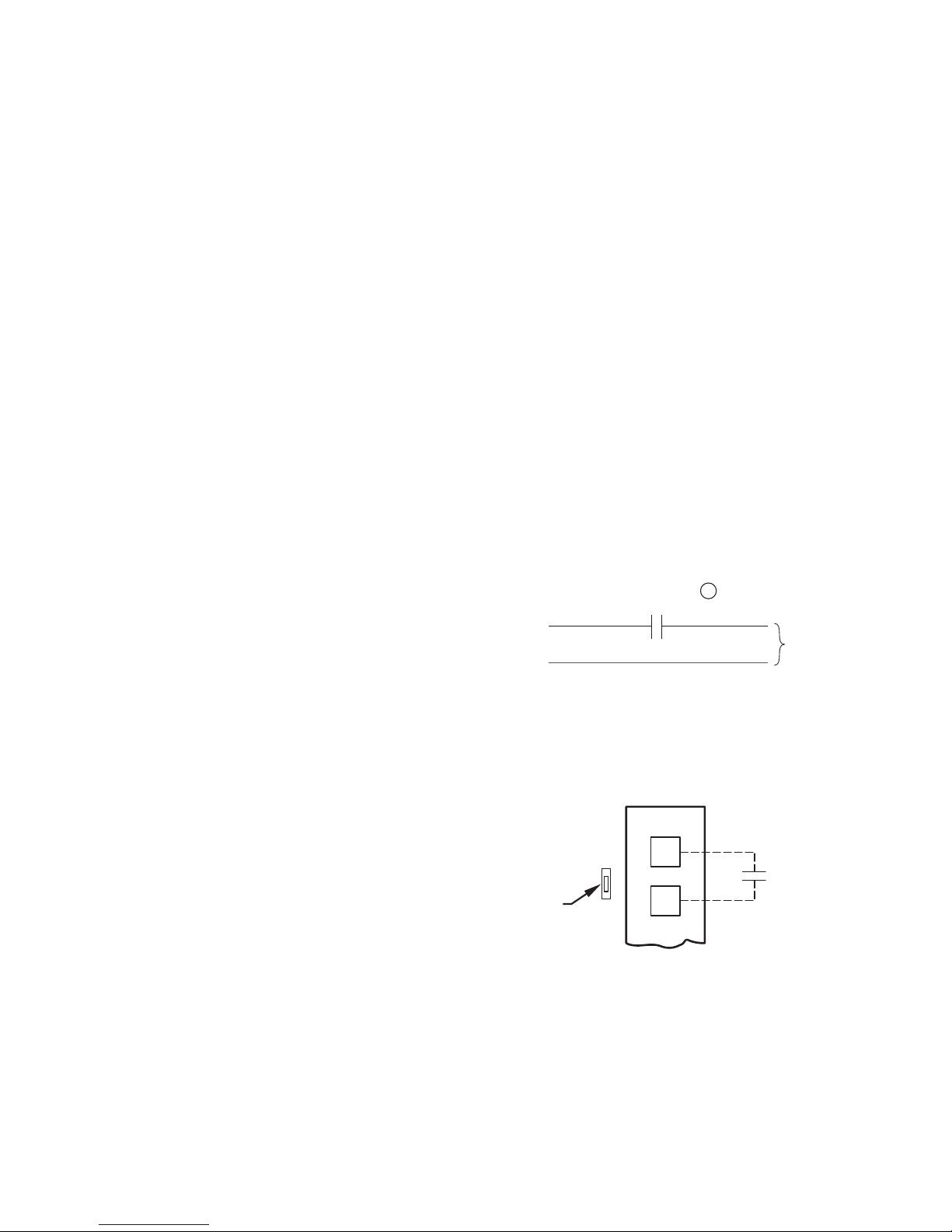
jumper J1 and wire in a standard humidistat (See Fig. 7).
e. DEHUMIDIFY AND SUPER DEHUMIDIFY
CAPABILITIES
This model unit is capable of responding to a signal from indoor
system control (Thermidistat™ or capable zoning control) to
operate in comfort control modes such as Super Dehumidify
Mode. Consult literature provided with indoor system control to
determine if these operating modes are available, and to see
control set up instructions. No special setup or wiring of unit is
required.
D. 583B Sequence of Operation
a. CONTINUOUS FAN
(1.) Thermostat closes circuit R to G—The Blower runs at
continuous fan airflow
b. COOLING MODE
Fig. 6—Humidifier Wiring-583B
A95317
HUMIDISTAT
TO HUMIDIFIER
HUMIDIFIER WIRING
HUM 1
(C)
HUM 2
(G)
24-VAC
Fig. 7—Humidistat Wiring for
De-Humidify Mode-583B
A95316
EASY SELECT
BOARD TERMINAL
BLOCK
D
H
J1
R
HUMIDISTAT
REMOVE
JUMPER
—4—
Page 5

(1.) If indoor temperature is above temperature set point and
humidity is below humidity set point, thermostat closes
circuits R to G, R to Y/Y2 and R to O—The unit delivers
single speed cooling airflow.
c. COOLING MODE-DEHUMIDIFICATION
(1.) If indoor temperature is above temperature set point and
humidity is above humidity set point, thermostat or Thermidistat™ closes circuits R to G, R to Y/Y2, R to O and
humidistat or Thermidistat™ opens R to DH—The unit
delivers airflow which is approximately 80 percent of the
nominal cooling airflow to increase the latent capacity of
the system.
d. COOLING MODE-SUPER DEHUMIDIFY OPERATION
(SEE QUICK REFERENCE GUIDE)
NOTE: The indoor control used, such as a Thermidistat™, must
be capable of providing Super Dehumidify operation mode and
control must be configured as outlined in its installation instructions. Consult indoor control literature to determine if control is
capable of providing Super Dehumidify inputs and for configuration instruction.
(1.) If the indoor temperature is below the temperature set
point and the humidity is above the humidity set point, the
Thermidistat™ closes circuit R to O, opens circuits R to
DH and R to G, and closes circuit R to Y/Y2. If circuit R
to G is closed (24-v.), the motor will deliver airflow at the
full cooling or cooling plus dehumidify mode requested
value. If circuit R to G is open (0–v.) for Super Dehumidify mode, the motor delivers reduced airflow to maximize the humidity removal of the system while minimizing
over cooling.
e. GAS HEATING MODE
(1.) Thermostat closes circuit R to W/W1—The unit delivers
the selected gas heat airflow. The IGC will control a 45
sec. blower “On” delay and a 45 sec. “Off” delay.
E. Easy Select™—683B
NOTE: Either the Bryant Thermidistat™ or Dual Fuel ther-
mostat is required for operation of the dual-fuel (683B) units.
Be sure to follow the installation instructions supplied with the
Thermidistat™. Either indoor temperature control must use
an outdoor air sensor to properly control heating operation.
EASY SELECT™ CONFIGURATION TAPS FOR 683B
Easy Select™ taps are used by the installer to configure a system.
The ICM motor uses the selected taps to modify its operation to a
pre-programmed table of airflows.
The unit must be configured to operate properly with system
components with which it is installed. To successfully configure a
basic system (see information printed on circuit board label located
next to select pins), move the 6 select wires to the pins which
match the components used (See Fig. 8).
a. GAS HEAT/CFM—SELECT GAS HEAT INPUT SIZE
Factory selected gas heat size should correspond to unit label.
b. AC/HP SIZE—SELECT SYSTEM SIZE INSTALLED
Factory selected air conditioner size should correspond to
capacity of unit installed. Installer should verify air conditioner
size to ensure that airflow delivered falls within proper range
for the size unit installed. This applies to all operational modes.
c. SYSTEM TYPE—SELECT SYSTEM TYPE INSTALLED
Factory selected on 683B for HP-EFF.
SELECT OPTIONS
1. HP-COMFORT provides approximately 315 CFM/ton for
higher normal heating air temperature and provides approximately 350 CFM/ton cooling airflow for good humidity re-
moval
2. HP-EFF (factory selected) Provides equal airflow for heating
and cooling modes to increase overall heat pump efficiency.
Provides approximately 400 CFM/ton.
d. AC/HP CFM ADJUST—SELECT NOMINAL, LOW, OR
HIGH AIRFLOW
The AC/HP CFM Adjust select is factory set to the High-HI
(NOM for 036, 060) tap. The CFM Adjust selections NOM/LO
will regulate airflow supplied for all operational modes, except
non-heat pump heating modes. HI provides 15 percent airflow
over nominal unit size selected and LO provides 10 percent
airflow below nominal unit size selected. Adjust selection
options are provided to adjust airflow supplied to meet individual installation needs for such things as noise, comfort, and
humidity removal (See Fig. 8, D as indicated).
e. ON/OFF DELAY—SELECT DESIRED
TIME DELAY PROFILE
Four motor operation delay profiles are provided to customize
and enhance system operation (See Fig. 8, E as indicated).
Selection options are:
(1.) The standard 90 sec off delay (Factory Setting) at 100
percent airflow in cooling or heat pump heating mode. In
gas heating mode, IGC will control a 45 sec “On” delay
and a 45 sec “Off” delay.
(2.) A 30 sec cooling delay with no airflow/ 90 sec off delay at
100 percent airflow profile is used when it is desirable to
allow system coils time to cool-down/heat-up in conjunction with the airflow in cooling or heat pump heating
mode.
(3.) A no delay option used for servicing unit or when a
thermostat is utilized to perform delay functions. In gas
heating mode IGC will control 45 sec on delay with no
airflow and 45 sec off delay.
Fig. 8—Detail of SPP Printed-Circuit Board
C01039
EASY SELECT
HEATER/MOTOR
GAS HEAT/CFM
090
1250
SEC1 SEC2
J1
AC/HP SIZE
036 030 024 018
AC
HP-COMFORT
HP-EFF
NOM HI
ENH
LO
SYSTEM TYPE
AC/HP CFM ADJUST
ON/OFF DELAY
CONTINUOUS FAN
MED HI YELLO
AUX1 HUM1
AUX2
24VAC
GRY
HUM2
YEL
WHT
BLK
ORN
BLU
VIO
060
1100
040
800
09030900
0
N/A
TM
J2
D
H
R
W
1
W
2
Y
1
Y/Y
2
G
O
C
9 PIN CONNECTOR
ICM PRINTED CIRCUIT BOARD
12 PIN CONNECTOR
A
B
C
D
E
F
—5—
Page 6
(4.) ENH (enhanced) selection provides a 30 sec. cooling &
heat pump on delay with no airflow, plus 150 seconds at 70
percent airflow and no off delay for added comfort. This
will minimize cold blow in heat pump operation and could
enhance system efficiency.
f. CONTINUOUS FAN—SELECT DESIRED FAN SPEED
WHEN THERMOSTAT IS SET ON CONTINUOUS FAN
(1.) LO speed—Factory setting, 50 percent cooling mode
airflow.
(2.) MED speed—Move connector to MED, 65 percent cooling
mode airflow.
(3.) HI speed—Move connector to HI, 100 percent cooling
mode airflow (See Fig. 8, F as indicated).
g. LOW-VOLTAGE CIRCUIT FUSING AND REFERENCE
The low-voltage circuit is fused by a board-mounted 5–amp
automotive fuse placed in series with the transformer SEC2 and
the R circuit. The C circuit of the transformer is referenced to
chassis ground through a printed circuit run at SEC1 connected
to metal standoff marked with ground symbol.
h. BASIC UNIT CONFIGURATION
The following basic configuration of the indoor motor will
provide ARI rated performance of the 683B. This BASIC
CONFIGURATION should be used when the rated ARI performance is required.
(1.) HEAT-Factory selected to match heat input size.
(2.) AC/HP Size-Factory selected to match system size, please
verify.
(3.) SYSTEM TYPE-Factory selected on 683B system for
HP-EFF.
(4.) AC/HP CFM ADJUST-Select HIGH for 042 & 048, NOM
for 036 & 060, and LO for 024 & 030.
(5.) ON/OFF DELAY-Factory selected 0/90 profile.
(6.) CONTINUOUS FAN-Select desired fan speed when ther-
mostat is set to continuous fan.
i. COMFORT OPTIONS—SUPER DEHUMIDIFY (See Quick
Reference Guide)
The Super Dehumidify option is possible when this unit is
installed with a field supplied Thermidistat™ control (SuperDehumidify does not require an outdoor temperature sensor).
The following configuration is recommended for maximum
cooling/dehumidifying comfort. This configuration will improve the comfort provided by the air conditioning system if
more humidity removal is desired. While providing this improved comfort, the system will operate efficiently, but not at
the published ARI SEER efficiency.
The following system configuration is recommended for maximum cooling/dehumidifying comfort (See Fig. 8).
(1.) HEAT-Factory selected to match gas heat size of unit
installed.
(2.) AC/HP Size-Factory selected to match system size, please
verify.
(3.) SYSTEM TYPE-Factory selected on 683B system for
HP-EFF.
(4.) AC/HP CFM ADJUST-Select NOM (Lo for 060).
(5.) ON/OFF DELAY-Select ENH profile.
(6.) CONTINUOUS FAN-Select desired fan speed when ther-
mostat is set to continuous fan.
(7.) LOW VOLTAGE CONNECTIONS-Make connections as
shown in ELECTRICAL CONNECTIONS section.
(8.) CONFIGURE THERMIDISTAT™-Follow Thermidis-
tat™ installation instructions for Super Dehumidify opera-
tion.
ACCESSORY INSTALLATION
a. AUXILIARY TERMINALS
The AUX and HUM terminals on the Easy Select™ Board are
tied directly to the G terminal, and provide a 24-v. signal
whenever the G terminal is energized (See Fig. 9). During
Super dehumidify mode, the G signal is not present and the
auxiliary terminals are not energized. If the installation includes
the use of this operating mode, do not use these terminals to
control accessories. See Electronic Air Cleaner and Humidifier
sections for further information.
b. ELECTRONIC AIR CLEANER CONNECTIONS
The AUX1 and AUX2 terminals are not always energized
during blower operations, as described above. When using an
electronic air cleaner with the unit, use Airflow Sensor P/N.
KEAAC0101AAA. The airflow sensor turns on electronic air
cleaner when the blower is operating.
c. HUMIDIFIER / THERMIDISTAT™ CONNECTIONS
Easy Select™ Board terminals HUM1 and HUM2 are provided
for direct connection to the low-voltage control of a humidifier
through a standard Thermidistat™ (See Fig. 9). These terminals
are energized with 24-v. when G thermostat signal is present
(See Fig. 10). Alternately, the 24-v. signal may be sourced from
the W and C on the 9 pin connector. When using a Thermidistat™ Control the 24-v. signal may be sourced directly from the
Thermidistat™ HUM terminal (See Fig. 8, 9 & 10).
d. DEHUMIDIFY CAPABILITY WITH STANDARD
THERMIDISTAT™ CONNECTION
Latent capacities for this unit are better than average systems. If
increased latent capacity is an application requirement, the ICM
board provides connection terminals for use of a Thermidistat™. The unit will detect the Thermidistat™ contacts opening
on increasing humidity and reduce its airflow to approximately
80 percent of nominal cooling mode airflow. This reduction
will increase the system latent capacity until the humidity falls
Fig. 9—Humidifier Wiring-683B
C01108
THERMIDISTAT ™
TO HUMIDIFIER
HUMIDIFIER WIRING
HUM 1
(C)
HUM 2
(G)
24-VAC
Fig. 10—Thermidistat™ Wiring for
De-Humidify Mode-683B
C01109
EASY SELECT
BOARD TERMINAL
BLOCK
D
H
J1
R
THERMIDISTAT
JUMPER
—6—
Page 7
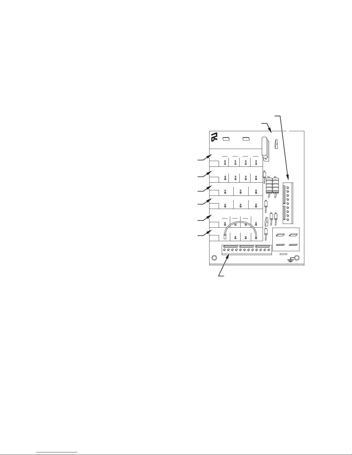
to a level which causes the Thermidistat™ to close its contacts.
When the contacts close, the airflow will return to 100 percent
of selected cooling airflow. To activate this mode wire in
Thermidistat™ see jumper in Fig. 10.
e. DEHUMIDIFY AND SUPER DEHUMIDIFY
CAPABILITIES
This model unit is capable of responding to a signal from
Thermidistat™ to operate in comfort control modes such as
Super Dehumidify Mode. Consult literature provided with
Thermidistat™ to determine if these operating modes are
available, and to see control set up instructions. No special
setup or wiring of unit is required.
F. 683B Sequence of Operation
a. CONTINUOUS FAN
(1.) Thermostat closes circuit R to G—The Blower runs at
continuous fan airflow
b. COOLING MODE
(1.) If indoor temperature is above temperature set point and
humidity is below humidity set point, thermostat closes
circuits R to G, R to Y/Y2 and R to O—The unit delivers
single speed cooling airflow.
c. COOLING MODE-DEHUMIDIFICATION
(1.) If indoor temperature is above temperature set point and
humidity is above humidity set point, Thermidistat™
closes circuits R to G, R to Y/Y2, R to O and Thermidistat™ opens R to DH—The unit delivers airflow which is
approximately 80 percent of the nominal cooling airflow to
increase the latent capacity of the system.
d. COOLING MODE-SUPER DEHUMIDIFY OPERATION
(SEE QUICK REFERENCE GUIDE)
NOTE: Thermidistat™ is capable of providing Super Dehumidify operation mode and must be configured as outlined in its
installation instructions. Consult indoor control literature to determine if control is capable of providing Super Dehumidify inputs
and for configuration instruction.
(1.) If the indoor temperature is below the temperature set
point and the humidity is above the humidity set point, the
Thermidistat™ closes circuit R to O, opens circuits R to
DH and R to G, and closes circuit R to Y/Y2. If circuit R
to G is closed (24-v.), the motor will deliver airflow at the
full cooling or cooling plus dehumidify mode requested
value. If circuit R to G is open (0–v.) for super dehumidify
mode, the motor delivers reduced airflow to maximize the
humidity removal of the system while minimizing over
cooling.
e. GAS HEATING MODE
(Occurs if outdoor temperature is below outdoor temperature
change over setpoint.)
(1.) Thermostat closes circuit R to W/W1—The unit delivers
the selected gas heat airflow. The IGC will control 45 sec.
on delay with no airflow and 45 sec. off delay.
f. HEAT PUMP HEATING MODE
(Occurs if outdoor temperature is above outdoor temperature
change over setpoint.)
(1.) Thermidistat™ closes circuit R to G and R to Y/Y2–The
unit delivers selected heat pump heating airflow.
g. HEATING MODE—SUPER COMFORT HEAT OPERA-
TION
NOTE: The Thermidistat™ is capable of providing Super Comfort Heat operation mode and must be configured as outlined in its
installation instructions. The system must be installed with appropriate outdoor temperature sensor. Consult Thermidistat™ literature for configuration instructions. Consult sensor instructions for
sensor installation details.
If the outdoor temperature is in the range of 12° to 40° F, the
Thermidistat™ closes circuit R to Y/Y2 and opens circuit R to G.
If circuit R to G is closed (24-v.), the motor will deliver airflow at
the full heating requested value. If circuit R to G is open (0-v.) for
maximum heating comfort, the motor delivers reduced airflow to
maximize the temperature and minimize the draft effect of the
heated air leaving the unit.
G. Easy Select™—702B & 602B
EASY SELECT™ CONFIGURATION TAPS FOR 702B &
602B
Easy Select™ taps are used by the installer to configure a system.
The ICM motor uses the selected taps to modify its operation to a
pre-programmed table of airflows.
The unit must be configured to operate properly with system
components with which it is installed. To successfully configure a
basic system (see information printed on circuit board label located
next to select pins), move the 6 select wires to the pins which
match the components used.
a. AUX HEAT kW/CFM—SELECT HEATER RANGE FOR
SIZE OF ELECTRIC HEATER INSTALLED
Installer must select the auxiliary heat airflow approved for
application with kW size heater installed. If no heater is
installed, this step can be skipped. Each select pin is marked
with a range of heaters for which airflow (also marked), is
approved. For increased comfort, select the narrowest kW range
matching the heater size, for example, 0–10 for 10–kW heater.
This airflow must be greater than the minimum for CFM for
electric heater application with the size system installed for safe
and continuous operation. (See Tables 16, 17 & 18 for airflow
delivery and minimum CFM.) Note that airflow marked is the
Fig. 11—Detail of SPP Printed-Circuit Board
C01033
EASY SELECT
HEATER/MOTOR
AUX HEAT KW/CFM
0-30
1075
SEC1 SEC2
J1
AC/HP SIZE
036 030 024 018
AC
HP-COMFORT
HP-EFF
NOM HI
ENH
LO
SYSTEM TYPE
AC/HP CFM ADJUST
ON/OFF DELAY
CONTINUOUS FAN
MED HI YELLO
AUX1 HUM1
AUX2
24VAC
GRY
HUM2
YEL
WHT
BLK
ORN
BLU
VIO
0-20
875
0-10
725
09030900
0
0-5
625
TM
J2
D
H
R
W
1
W
2
Y
1
Y/Y
2
G
O
C
9 PIN CONNECTOR
ICM PRINTED CIRCUIT BOARD
12 PIN CONNECTOR
A
B
C
D
E
F
—7—
Page 8

airflow which will be supplied in emergency heat mode and
heating mode on air conditioners when electric heat is the
primary heating source. In heat pump heating mode when
electric heaters are energized, the ICM will run the higher of
heat pump heating airflow and electric heater airflow to ensure
safe heater operation. The factory selection is the largest heater
range approved (See Fig. 11, A as indicated).
b. AC/HP SIZE—SELECT SYSTEM SIZE INSTALLED
The factory setting for air conditioner or heat pump size is the
size which matches the model of packaged unit installed.
Installer should verify air conditioner or heat pump size to
ensure that airflow delivered falls within proper range for the
size unit installed. This applies to all operational modes with
the exception of electric heat modes (See Fig. 11, B as
indicated).
c. SYSTEM TYPE—SELECT SYSTEM TYPE INSTALLED
The type of system will be factory selected (see below for
details):
(1.) AC-Air conditioner (Factory Selected for 702B)
(2.) HP-COMFORT—Heat Pump Comfort provides approxi-
mately 315 CFM per ton for higher normal heating air
delivery temperature and provides approximately 350
CFM per ton cooling airflow for good humidity removal.
(3.) HP-EFF (Factory Selected for 602B)— Heat Pump Effi-
ciency provides same airflow for heating and cooling
modes to increase overall HP efficiency; approximately
350 CFM per ton.
d. AC/HP CFM ADJUST—SELECT NOMINAL, LOW, OR
HIGH AIRFLOW
The AC/HP CFM Adjust select is factory set to the High-Hi
(NOM for 060) tap. The CFM Adjust selections NOM/LO will
regulate airflow supplied for all operational modes, except
non-heat pump heating modes. HI provides 15 percent airflow
over nominal unit size selected and LO provides 10 percent
airflow below nominal unit size selected. CFM Adjust selection
options are provided to adjust airflow supplied to meet individual installation needs for such things as noise, comfort, and
humidity removal (See Fig. 11, D as indicated).
e. ON/OFF DELAY—SELECT DESIRED
TIME DELAY PROFILE
Four motor operation delay profiles are provided to customize
and enhance system operation (See Fig. 11, E as indicated).
Selection options are:
(1.) The standard 90 sec off delay (Factory Setting) at 100
percent airflow in cooling or heat pump heating mode.
(2.) A 30 sec cooling delay with no airflow/90 sec off delay at
100 percent airflow profile is used when it is desirable to
allow system coils time to heat-up/cool-down in conjunction with the airflow in cooling or heat pump heating
mode.
(3.) A no delay option used for servicing unit or when a
thermostat is utilized to perform delay functions.
(4.) ENH, enhanced selection, provides a 30 sec cooling on
delay with no airflow/ plus 150 sec at 70 percent airflow/
no off delay for added comfort.
This will minimize cold blow in heat pump operation
(602B only) and could enhance system efficiency.
f. CONTINUOUS FAN—SELECT DESIRED FAN SPEED
WHEN THERMOSTAT IS SET ON CONTINUOUS FAN
(1.) LO speed—Factory setting, 50 percent cooling mode
airflow.
(2.) MED speed—Move connector to MED, 65 percent cooling
mode airflow.
(3.) HI speed—Move connector to HI, 100 percent cooling
mode airflow (See Fig. 11, F as indicated).
g. LOW-VOLTAGE CIRCUIT FUSING AND REFERENCE
The low-voltage circuit is fused by a board-mounted 5–amp
automotive fuse placed in series with the transformer SEC2 and
the R circuit. The C circuit of the transformer is referenced to
chassis ground through a printed circuit run at SEC1 connected
to metal standoff marked with ground symbol.
h. BASIC UNIT CONFIGURATION
The following basic configuration of the indoor motor will
provide ARI rated performance of the System. This BASIC
CONFIGURATION should be used when the rated ARI performance is required, or if system enhancements such as super
dehumidify are not needed.
(1.) AUX HEAT kW/CFM-Select the heater range for the size
of electric heater installed (skip this step if no heater is
installed).
(2.) AC/HP SIZE-Factory selected to match system size in-
stalled, please verify.
(3.) SYSTEM TYPE-Factory selected AC (702B) or HP-EFF
(602B).
(4.) AC/HP CFM ADJUST-Select HIGH for 042 & 048, NOM
for 036 & 060, and LO for 024 & 030.
(5.) ON/OFF DELAY-Select 0/90 profile.
(6.) CONTINUOUS FAN-Select desired fan speed when ther-
mostat is set to continuous fan.
i. COMFORT OPTIONS—SUPER DEHUMIDIFY (See Quick
Reference Guide)
The Super Dehumidify option is possible when this unit is
installed with a field supplied Thermidistat™ control (Super
Dehumidify does not require an outdoor temperature sensor).
The following configuration is recommended for maximum
cooling/dehumidifying comfort: This configuration will improve the comfort provided by the air conditioning system if
more humidity removal is desired. While providing this improved comfort, the system will operate efficiently, but not at
the published HSPF or ARI SEER efficiency.
The following system configuration is recommended for maximum heating and cooling/dehumidifying comfort (See Fig. 11).
(1.) AUX HEAT kW/CFM-Select the narrowest heater range to
match size of electric heater installed (skip this step if no
heater is installed).
(2.) AC/HP Size-Factory selected to match system size in-
stalled, please verify.
(3.) SYSTEM TYPE-Select system type HP-COMFORT (for
heat pump system) or AC (for air conditioner system).
(4.) AC/HP CFM ADJUST-Select NOM (Lo for 060).
(5.) ON/OFF DELAY-Select ENH profile.
(6.) CONTINUOUS FAN-Select desired fan speed when ther-
mostat is set to continuous fan.
(7.) DEHUMIDIFY MODE-Remove J1 jumper to activate.
(8.) LOW VOLTAGE CONNECTIONS-Make connections as
shown in ELECTRICAL CONNECTIONS section.
(9.) CONFIGURE THERMIDISTAT™ (or capable zoning
system)-Following its installation instructions for Super
Dehumidify and Super Comfort Heat operation.
—8—
Page 9
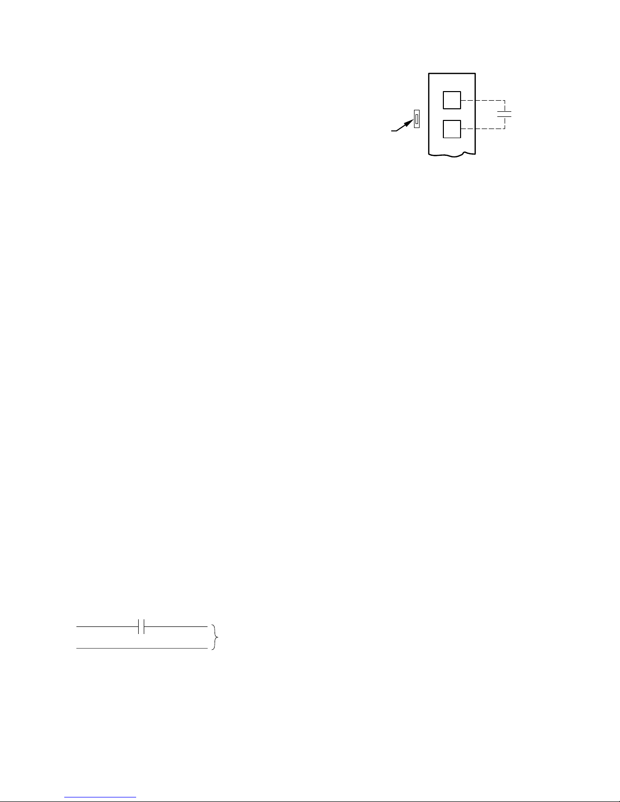
This configuration provides the following comfort enhancements:
(a.) A 30 sec blower on delay with 150 sec at 70 percent
airflow to allow the indoor coil to warm up or cool
down before the blower is asked to deliver 100 percent
airflow reducing the cold blow sensation at start up in
heating and allowing the indoor coil to more quickly
reach wet coil operating conditions in cooling.
(b.) A no blower off delay eliminates cold blow which may
be associated with running the blower after shut down
of the compressor and avoids re-evaporation of condensed moisture after cooling/dehumidifying operation.
(c.) Lower airflow while the compressor is running to
reduce draft effects and increase heating air temperature and improved humidity control during cooling
operation.
ACCESSORY INSTALLATION
a. ACCESSORY ELECTRIC HEATERS
Electric heaters may be installed with the 702B & 602B units
per instructions supplied with electric heater package. See unit
rating plate for factory-approved electric heater kits.
b. AUXILIARY TERMINALS
The AUX and HUM terminals on the Easy Select™ Board are
tied directly to the G terminal, and provide a 24-v. signal
whenever the G terminal is energized (See Fig. 12). During
Super dehumidify mode, the G signal is not present and the
auxiliary terminals are not energized. If the installation includes
the use of the operating mode, do not use these terminals to
control accessories. See Electronic Air Cleaner and Humidifier
sections for further information.
c. ELECTRONIC AIR CLEANER CONNECTIONS
The AUX1 and AUX2 terminals are not always energized
during blower operations, as described above. When using an
electronic air cleaner with the unit, use Airflow Sensor P/N
KEAAC0101AAA. The airflow sensor turns on electronic air
cleaner when the blower is operating.
d. HUMIDIFIER/HUMIDISTAT CONNECTIONS
Easy Select™ Board terminals HUM1 and HUM2 are provided
for direct connection to the low-voltage control of a humidifier
through a standard humidistat (See Fig. 12). These terminals are
energized with 24-v. when G thermostat signal is present. (See
Fig. 11, 12 & 13). Alternately, the 24-v. signal may be sourced
from the W and C circuit board connections. When using a
Thermidistat™ Control, Zone Perfect Plus or Comfort Zone II,
the 24-v. signal may be sourced directly from the Thermidistat™ HUM terminal.
e. DEHUMIDIFY CAPABILITY WITH STANDARD
HUMIDISTAT CONNECTION
Latent capacities for these units are better than average systems.
If increased latent capacity is an application requirement, the
circuit board provides connection terminals for use of a
standard humidistat. The unit will detect the humidistat contacts
opening on increasing humidity and reduce its airflow to
approximately 80 percent of nominal cooling mode airflow.
This reduction will increase the system latent capacity until the
humidity falls to a level which causes the humidistat to close its
contacts. When the contacts close, the airflow will return to 100
percent of selected cooling airflow. To activate this mode,
remove jumper J1 and wire in a standard humidistat ( See Fig.
13).
f. DEHUMIDIFY AND SUPER DEHUMIDIFY CAPABILITIES
these models are capable of responding to a signal from indoor
system control (thermostat, Thermidistat™, zoning control) to
operate in comfort control modes such as Super Dehumidify
Mode. Consult literature provided with indoor system control to
determine if these operating modes are available, and to see
control set up instructions. No special setup or wiring of unit is
required.
H. 702B & 602B Sequence Of Operation
a. CONTINUOUS FAN
(1.) Thermostat closes circuit R to G—The Blower runs at
continuous fan airflow.
b. COOLING MODE-LOW HUMIDITY
(1.) If indoor temperature is above temperature set point and
humidity is below humidity set point, thermostat closes
circuits R to G, R to Y/Y2 and R to O—The unit delivers
cooling airflow.
c. COOLING MODE-DEHUMIDIFICATION
(1.) If indoor temperature is above temperature set point and
humidity is above humidity set point, thermostat or Thermidistat™ closes circuits R to G, R to O, and R to Y/Y2
and humidistat or Thermidistat™ opens R to DH—The
unit delivers airflow which is approximately 80 percent of
the nominal cooling airflow to increase the latent capacity
of the system.
d. COOLING MODE-SUPER DEHUMIDIFY OPERATION (see
quick reference guide)
NOTE: The indoor control used, such as a Thermidistat™, must
be capable of providing Super Dehumidify operation mode and
control must be configured as outlined in its installation instructions. Consult indoor control literature to determine if control is
capable of providing Super Dehumidify inputs and for configuration instruction.
(1.) If the indoor temperature is below the temperature set
point and the humidity is above the humidity set point, the
Thermidistat™ closes circuit R to O, opens circuits R to
DH and R to G, and cycles circuit R to Y/Y2. If circuit R
to G is closed (24-v.), the motor will deliver airflow at the
full cooling or cooling plus dehumidify mode requested
Fig. 12—Humidifier Wiring for 702B & 602B
A95317
HUMIDISTAT
TO HUMIDIFIER
HUMIDIFIER WIRING
HUM 1
(C)
HUM 2
(G)
24-VAC
Fig. 13—Humidistat Wiring for De-Humidify Mode-for
702B & 602B
A95316
EASY SELECT
BOARD TERMINAL
BLOCK
D
H
J1
R
HUMIDISTAT
REMOVE
JUMPER
—9—
Page 10

value. If circuit R to G is open (0–v.) for super dehumidify
mode, the motor delivers reduced airflow to maximize the
humidity removal of the system while minimizing over
cooling.
e. ELECTRIC HEATING MODE
(1.) Thermostat closes circuit R to W/W1, or W2—The unit
delivers the selected electric heat airflow. There are no on
or off delays.
f. HEAT PUMP HEATING MODE (602B only)
(1.) Thermostat closes circuits R to G and R to Y/Y2—The unit
delivers selected heat pump heating airflow.
g. HEAT PUMP HEATING WITH AUXILIARY
ELECTRIC HEAT (602B only)
(1.) Thermostat closes circuits R to G, R to Y/Y2 and R to
W/W1 or W2 (and R to O in the case of defrost).
In the event that electric heating is called for by the thermostat
while the heat pump is also operating in either heating or
defrost modes, the motor will modify its airflow output, if
necessary, to provide an airflow which is defined as safe for the
operation of the electric heater during heat pump operation.
That airflow is the greater of the heat pump heating airflow and
the electric heater only airflow.
h. HEATING MODE—SUPER COMFORT HEAT OPERA-
TION
NOTE: The indoor control used, such as a Thermidistat™, must
be capable of providing Super Comfort Heat operation mode and
control must be configured as outlined in its installation instructions. The system must be installed with appropriate outdoor
temperature sensor. Consult indoor control literature to determine
if control is capable and for configuration instructions. Consult
indoor control instructions and sensor instructions for sensor
installation details.
If the outdoor temperature is in the range of 12° to 40° F, the
Thermidistat™ closes circuit R to Y/Y2 and opens circuit R to G.
If circuit R to G is closed (24-v.), the motor will deliver airflow at
the full heating requested value. If circuit R to G is open (0-v.) for
maximum heating comfort, the motor delivers reduced airflow to
maximize the temperature and minimize the draft effect of the
heated air leaving the unit.
ICM FIOP START-UP
ICM General Start Up
CHECKING AND ADJUSTING REFRIGERANT CHARGE
The refrigerant system is fully charged with Puron® (R-410A)
refrigerant, and is tested and factory sealed.
NOTE: Adjustment of the refrigerant charge is not required
UNLESS the unit is suspected of not having the proper R-410A
charge.
The charging label and the tables shown refer to system temperatures and pressures. The temperatures and pressures are calculated
at rated airflow. When charging unit, set to rated airflow. A
refrigerant charging chart label is attached to the outside of the
compressor access door. The chart includes the required suction
line temperature at given suction line pressures and outdoor
ambients. An accurate superheat, thermocouple- or thermistor-type
thermometer, and gage manifold are required when using the
superheat charging method for evaluating the unit charge. Do not
use mercury or small dial-type thermometers because they are
not adequate for this type of measurement
IMPORTANT: When evaluating the refrigerant charge, an indicated adjustment to the specified factory charge must always be
very minimal. If a substantial adjustment is indicated, an abnormal
condition exists somewhere in the cooling system, such as insufficient airflow across either one or both coils.
I. 583B START-UP (ICM FIOP)
CHECKING COOLING CONTROL OPERATION-Start and
check the unit for proper cooling control operation as follows:
(1.) Place room thermostat SYSTEM switch in OFF position.
Observe that blower motor starts when FAN switch is
placed in ON position and shuts down when FAN switch
is placed in AUTO position. Note fan delay time setting
selected on the Easy Select™ board. (See Easy Select
Section.)
(2.) Place SYSTEM switch in COOL position and FAN switch
in AUTO position. Set cooling control below room temperature. Observe that compressor, condenser fan, and
evaporator blower motors start. Observe that cooling cycle
shuts down when control setting is satisfied. The evaporator fan will continue to run for the time setting selected
on Easy Select™ board. (See Easy Select Section.)
(3.) When using an auto-changeover room thermostat, place
both SYSTEM and FAN switches in AUTO position.
Observe that unit operates in heating mode when temperature control is set to “call for heating” (above room
temperature) and operates in cooling mode when temperature control is set to “call for cooling” (below room
temperature).
AIRFLOW AND TEMPERATURE RISE-The heating section for
each size unit is designed and approved for heating operation
within the temperature rise range stamped on the unit rating plate.
Table 15 shows the approved temperature rise range for each
heating input, and the air delivery (CFM) at various temperature
rise ranges.
The heating operation airflow must produce a temperature rise that
falls with in the approved range.
Refer to Indoor Airflow and Airflow Tables on the following
pages to adjust heating airflow when required.
CHECK HEATING CONTROL-Start and check the unit for
proper heating control operation as follows. (see furnace lighting
instructions located inside burner or blower access panel.):
(1.) Place room thermostat SYSTEM switch in the HEAT
position and the FAN switch in the AUTO position.
(2.) Set the heating temperature control of the thermostat above
room temperature.
(3.) The induced-draft motor will start.
(4.) After a call for heating, the main burner should light with
in 5 sec. If the burners still do not light, this sequence is
repeated. If the burners do not light within 15 minutes from
the initial call for heat, there is a lockout. To reset the
lockout control, break the 24-v. power to W.
(5.) The indoor fan will turn on 45 sec after the flame has been
established. The indoor fan will turn off according to time
delay selected on the Easy Select™ board (See Easy Select
Section) after the thermostat has been satisfied.
II. 683B START-UP (ICM FIOP)
Also refer to the Thermidistat™ instructions for start up and
check out of the system.
(1.) FAN OPERATION—
The fan button on Thermidistat™ switches fan icon
between AUTO and ON. While ON is displayed, output
will be on, turning fan on. Allow up to 10 sec. after button
is pressed for fan to turn on and off. the fan will continue
to run for the time setting selected on the Easy Select™
board after AUTO icon is displayed.
(2.) COOLING MODE—
Press MODE button on the Thermidistat™ until COOL
icon is displayed. Cooling begins within 10 sec. and
—10—
Page 11

remains on for 4 minutes. Observe that compressor,
outdoor fan and indoor blower motors start after the call
for Cooling. At the end of 4 minutes, the cooling cycle
stops and the MODE reverts back to OFF. The Indoor
Blower continues to run for the time selected on the Easy
Select™ board after OFF icon is displayed.
(3.) HEAT PUMP HEATING—
Press MODE button on the Thermidistat™ until HEAT
icon is displayed. Heat pump heating begins within 10 sec.
and remains on for 4 minutes. Observe that the compressor, outdoor fan and indoor blower come on. At the end of
the 4 minutes, heating cycle stops and the MODE reverts
back to OFF. The indoor blower continues to run for the
time selected on the Easy Select™ Board after the OFF
icon is displayed. Heating maybe turned off anytime
during the 4 minute cycle by pressing MODE button until
OFF is displayed.
(4.) GAS HEAT MODE—
Press MODE button until E-HEAT(Emergency Heat or
Back-Up Heat) icon is displayed. Gas heating begins
within 10 sec. and remains on for 4 minutes. The induced
draft motor should start immediately. The burners should
light within 5 sec. of E-HEAT call. The indoor blower will
turn on 45 sec. after the flame has been established. Gas
heating stops at the end of 4 minutes and MODE reverts
back to OFF. The indoor blower continues to run for the
time selected on the Easy Select™ Board after the OFF
icon is displayed.
NOTE: If the burners do not light, this lighting sequence is
repeated for 15 minutes from the initial call for E-HEAT. If after
15 minutes the burners do not light, there will be a lockout. To
reset the burner lockout control, break the 24-v. power to “W”.
(5.) AUTOMATIC CHANGE-OVER—
To test AUTO CHANGE-OVER function between COOL
and HEAT:
Enable the AUTO CHANGE-OVER mode during Thermidistat™ set-up. Refer to the Thermidistat™ literature for
details. Observe that the unit operates in cooling when in
COOL MODE (when setting is below room temperature)
and HEAT MODE (when setting is above room temperature).
AIRFLOW AND TEMPERATURE RISE-The heating section for
each size unit is designed and approved for heating operation
within the temperature rise range stamped on the unit rating plate.
Table 15 shows the approved temperature rise range for each
heating input, and the air delivery (CFM) at various temperature
rise ranges.
The heating operation airflow must produce a temperature rise that
falls with in the approved range.
Refer to Indoor Airflow and Airflow Tables on the following
pages to adjust heating airflow when required.
III. 702B: START-UP (ICM FIOP)
CHECKING COOLING CONTROL OPERATION–Start and
check the unit for proper cooling control operation as follows:
(1.) Place room thermostat SYSTEM switch in OFF position.
Observe that blower motor starts when FAN switch is
placed in ON position and shuts down when FAN switch
is placed in AUTO position.
(2.) Place SYSTEM switch in COOL position and FAN switch
in AUTO position. Set cooling control below room temperature. Observe that compressor, condenser fan, and
evaporator blower motors start. Observe that cooling cycle
shuts down when control setting is satisfied. The evaporator fan will continue to run for the selected off delay.
(3.) When using an auto-changeover room thermostat, place
both SYSTEM and FAN switches in AUTO positions.
Observe that unit operates in heating mode when temperature control is set to ‘‘call for heating’’ (above room
temperature) and operates in cooling mode when temperature control is set to ‘‘call for cooling’’ (below room
temperature).
NOTE: Once the compressor has started and then has stopped, it
will not start again until 5 minutes have elapsed. (The cooling
cycle remains ‘‘on’’ until the room temperature drops to point that
is slightly below the cooling control setting of the room thermostat.
At this point, the thermostat ‘‘breaks’’ the circuit between thermostat terminal R to terminals Y and G.) These open circuits
de-energize contactor coil C and ICM board. The condenser and
compressor motors stop. After the time delay setting selected on
the Easy Select™ board (See Easy Select Section) , the blower
motor stops. The unit is in a ‘‘standby’’ condition, waiting for the
next ‘‘call for cooling’’ from the room thermostat.
IV. 602B: START-UP (ICM FIOP)
CHECKING COOLING AND HEATING CONTROL OPERATION– Start and check the unit for proper control operation as
follows:
(1.) Place room thermostat SYSTEM switch or MODE control
in OFF position. Observe that blower motor starts when
FAN mode is placed in FAN ON position and shuts down
according to time delay selected on the Easy Select™
board (See Easy Select Section) when FAN MODE switch
is placed in AUTO position.
(2.) Thermostat:
When the room temperature rises to a point that is slightly
above the cooling control setting of the thermostat, the
thermostat completes the circuit between thermostat terminal R to terminals Y, O and G. These completed circuits
through the thermostat connect contactor coil (C) (through
unit wire Y) and ICM board (through unit wire G) across
the 24-v. secondary of transformer (TRAN).
Thermidistat™ or Thermostat and Humidistat:
When the room temperature rises to a point that is slightly
above the cooling control setting of the thermostat, the
thermostat completes the circuit between thermostat terminal R to terminals Y, O, DH, and G. These completed
circuits through the thermostat connect contactor coil (C)
(through unit wire Y) and ICM board (though unit wire G)
across the 24-v. secondary of transformer (TRANS).
(3.) Place system switch or MODE control in HEAT position.
Set control above room temperature. Observe that compressor, outdoor fan, and indoor blower motors start.
Observe that heating cycle shuts down according to time
delay selected on the Easy Select™ board (See Easy Select
Section) when control setting is satisfied.
(4.) When using an automatic changeover room thermostat,
place both SYSTEM or MODE control and FAN mode
switches in AUTO positions. Observe that unit operates in
Cooling mode when temperature control is set to “call for
Cooling” (below room temperature), and unit operates in
Heating mode when temperature control is set to “call for
Heating” (above room temperature).
NOTE: Once the compressor has started and then has stopped, it
should not be started again until 5 minutes have elapsed. The
cooling cycle remains ‘‘on’’ until the room temperature drops to
point that is slightly below the cooling control setting of the room
thermostat. At this point, the thermostat ‘‘breaks’’ the circuit
between thermostat terminal R to terminals Y and G. These open
circuits de-energize contactor coil C and ICM board. The condenser and compressor motors stop. After the time delay setting
selected on the Easy Select™ board (See Easy Select Section) , the
—11—
Page 12
blower motor stops. The unit is in a ‘‘standby’’ condition, waiting
for the next ‘‘call for cooling’’ from the room thermostat. The 5
minute compressor delay also applies to heat pump heating mode.
ELECTRICAL DATA & SCHEMATICS—ICM FIOP
I. PHYSICAL DATA & ELECTRICAL SCHEMATICS
Use the Physical Data and Electrical Tables on the following pages
for information that applies to Bryant Puron® units with the ICM
indoor motor FIOP.
AIRFLOW & TEMPERATURE RISE TABLES—ICM
FIOP
II. TABLES FOR SYSTEM SET-UP
Use the Airflow and Temperature Rise Tables on the following
pages for information that applies to Bryant Puron® units with the
ICM indoor motor FIOP.
CARE AND MAINTENANCE
Indoor Blower and Motor
NOTE: All motors are pre-lubricated. Do not attempt to lubricate
these motors. For longer life, operating economy, and continuing
efficiency, clean accumulated dirt and grease from the blower
wheel and motor annually.
WARNING: Disconnect and tag electrical power to the
unit before cleaning and lubricating any blower motor
and wheel. On units with gas heat, turn off the gas supply
before disconnecting the electrical power. Failure to
adhere to this warning could cause serious injury or
death.
To clean the blower motor and wheel:
1. 1. Remove and disassemble blower assembly as follows:
a. Remove unit access panel.
b. Carefully pivot blower access panel outward towards the
electrical box. Route wiring above blower access panel.
c. Disconnect the 5 and 16 pin plugs at the blower motor.
d. On all units, remove blower assembly from unit. Re-
move screws securing blower to vertical partition and
slide assembly out. Be careful not to tear insulation in
blower compartment.
e. Ensure proper reassembly by marking blower wheel and
motor in relation to blower housing before disassembly.
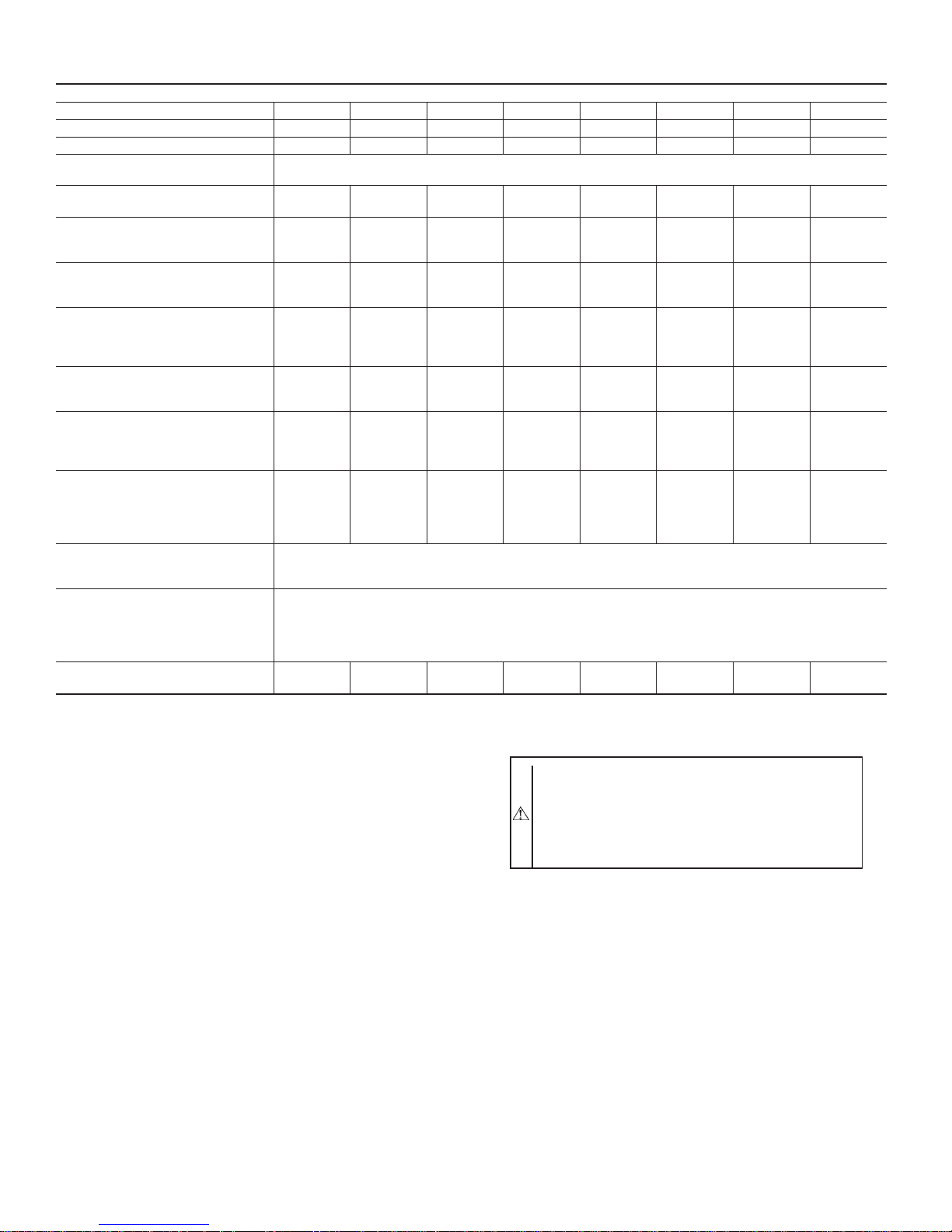
TABLE 1—ICM FIOP PHYSICAL DATA—UNIT 583B
THIS DATA APPLIES TO 583B UNITS WITH THE ICM INDOOR MOTOR FIOP
UNIT SIZE 583B 024040 024060 030040 030060 036060 036090 042060 042090
NOMINAL CAPACITY (ton) 2 2 2-1/2 2-1/2 3 3 3-1/2 3-1/2
OPERATING WEIGHT (lb.) 290 290 313 313 321 321 382 382
COMPRESSORS
Quantity
Scroll
1
REFRIGERANT (R-410A)
Quantity (lb.)
5.0 5.0 5.5 5.5 6.9 6.9 9.0 9.0
REFRIGERANT METERING DEVICE
Orifice ID (in.)
Check-Flo-Rater™ Piston
.057 .057 .057 .057 .065 .065 .070 .070
CONDENSER COIL
Rows...Fins/in.
Face Area (sq ft)
1...17
10.9
1...17
10.9
1...17
12.7
1...17
12.7
2...17
9.1
2...17
9.1
2...17
12.3
2...17
12.3
CONDENSER FAN
Nominal Cfm
Diameter (in.)
Motor HP (Rpm)
2350
22
1/8 (825)
2350
22
1/8 (825)
2350
22
1/8 (825)
2350
22
1/8 (825)
2350
22
1/8 (825)
2350
22
1/8 (825)
2350
22
1/8 (825)
2350
22
1/8 (825)
EVAPORATOR COIL
Rows...Fins/in.
Face Area (sq ft)
3...15
3.7
3...15
3.7
3...15
3.7
3...15
3.7
3...15
3.7
3...15
3.7
3...15
4.7
3...15
4.7
EVAPORATOR BLOWER
Nominal Airflow (Cfm)
Size (in.)
Motor (HP)
800
10X10
1/2
800
10X10
1/2
1000
10X10
1/2
1000
10X10
1/2
1200
11X10
3/4
1200
11X10
3/4
1400
11X10
3/4
1400
11X10
3/4
FURNACE SECTION*
Burner Orifice No. (Qty...Drill Size)
Natural Gas
Burner Orifice No. (Qty...Drill Size)
Propane Gas
2...44
2...50
2...38
2...46
2...44
2...50
2...38
2...46
2...38
2...46
3...38
3...46
2...38
2...46
3...38
3...46
HIGH-PRESSURE SWITCH (psig)
Cutout
Reset (Auto)
610±15
420±25
LOSS-OF-CHARGE/LOW-
PRESSURE SWITCH
(Liquid Line) (psig)
Cutout
Reset (Auto)
20±5
45±10
RETURN-AIR FILTERS (in.)
Throwaway
20X20X1 20X20X1 20X20X1 20X20X1 20X24X1 20X24X1 24X30X1 24X30X1
* Based on altitude of 0 to 2000 ft.
—12—
Page 13
f. Loosen set-screw that secures wheel to motor shaft,
remove screws that secure motor mount brackets to
blower housing, and slide motor and motor mount out of
blower housing.
2. Remove and clean blower wheel as follows:
a. Ensure proper reassembly by marking wheel orientation.
b. Lift wheel from housing. When handling and/or cleaning
blower wheel, be sure not to disturb balance weights
(clips) on blower wheel vanes.
c. Remove caked-on dirt from wheel and housing with a
brush. Remove lint and/or dirt accumulations from wheel
and housing with vacuum cleaner, using soft brush
attachment. Remove grease and oil with mild solvent.
d. Reassemble wheel into housing.
e. Reassemble motor into housing. Be sure set-screw(s) are
tightened on motor shaft flats and not on round part of
shaft.
f. Pivot blower access panel back into place. Adjust wire
assemblies so that wiring follows proper pathways.
g. Reinstall unit access panel.
3. Restore electrical power, then gas supply to unit. Start unit
and check for proper blower rotation and motor speeds
during heating and cooling cycles.
TROUBLESHOOTING
START-UP CHECKLIST
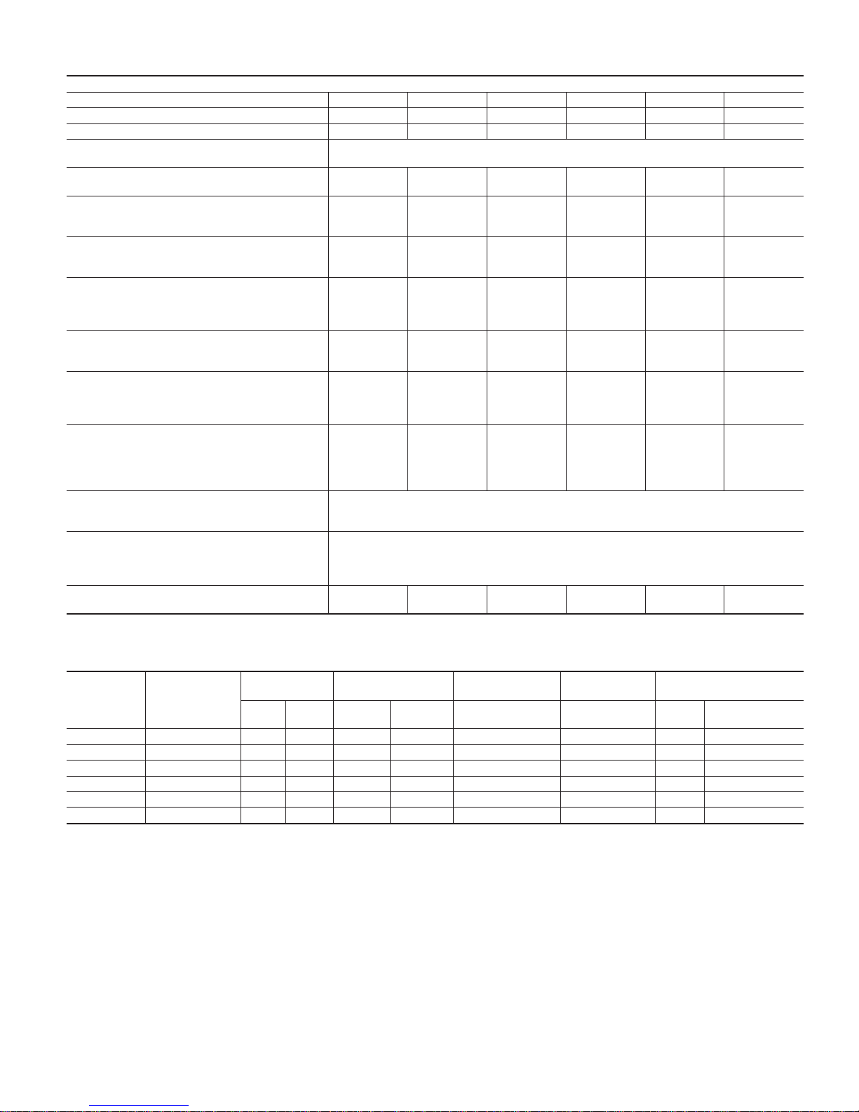
TABLE 2—ICM FIOP PHYSICAL DATA—UNIT 583B (CONTINUED)
THIS DATA APPLIES TO 583B UNITS WITH THE ICM INDOOR MOTOR FIOP
UNIT SIZE 583B 048090 048115 048130 060090 060115 060130
NOMINAL CAPACITY (ton) 444555
OPERATING WEIGHT (lb.) 421 421 421 468 468 468
COMPRESSORS
Quantity
Scroll
1
REFRIGERANT (R-410A)
Quantity (lb.)
9.5 9.5 9.5 10.0 10.0 10.0
REFRIGERANT METERING DEVICE
Orifice ID (in.)
Check-Flo-Rater™ Piston
.073 .073 .073 .086 .086 .086
CONDENSER COIL
Rows...Fins/in.
Face Area (sq ft)
2...17
12.3
2...17
12.3
2...17
12.3
2...17
16.4
2...17
16.4
2...17
16.4
CONDENSER FAN
Nominal Cfm
Diameter (in.)
Motor Hp (Rpm)
3300
22
1/4 (1100)
3300
22
1/4 (1100)
3300
22
1/4 (1100)
3300
22
1/4 (1100)
3300
22
1/4 (1100)
3300
22
1/4 (1100)
EVAPORATOR COIL
Rows...Fins/in.
Face Area (sq ft)
4...15
4.7
4...15
4.7
4...15
4.7
4...15
4.7
4...15
4.7
4...15
4.7
EVAPORATOR BLOWER
Nominal Airflow (Cfm)
Size (in.)
Motor (HP)
1600
11X10
3/4
1600
11X10
3/4
1600
11X10
3/4
2000
11X10
1.0
2000
11X10
1.0
2000
11X10
1.0
FURNACE SECTION*
Burner Orifice No. (Qty...Drill Size)
Natural Gas
Burner Orifice No. (Qty...Drill Size)
Propane Gas
3...38
3...46
3...33
3...42
3...31
3...41
3...38
3...46
3...33
3...42
3...31
3...41
HIGH-PRESSURE SWITCH (psig)
Cutout
Reset (Auto)
610±15
420±25
LOSS-OF-CHARGE/LOW-PRESSURE SWITCH
(Liquid Line) (psig)
Cutout
Reset (Auto)
20±5
45±10
RETURN-AIR FILTERS (in.)
Throwaway
24X30X1 24X30X1 24X30X1 24X30X1 24X30X1 24X30X1
* Based on altitude of 0 to 2000 ft.
TABLE 3—583B WITH ICM FIOP ELECTRICAL DATA
UNIT
SIZE 583B
V-PH-HZ
VOLTAGE
RANGE
COMPRESSOR
OUTDOOR FAN
MOTOR
INDOOR FAN
MOTOR
POWER SUPPLY
MIN MAX RLA LRA FLA FLA MCA
MAX FUSE
OR CKT. BKR.
024 208/230–1–60 187 253 13.5 61.0 0.9 4.3 22.1 30
030 208/230–1–60 187 253 14.7 73.0 0.9 4.3 23.6 30
036 208/230–1–60 187 253 15.4 83.0 0.9 6.8 27.0 35
042 208/230–1–60 187 253 18.6 105.0 0.9 6.8 31.0 40
048 208/230–1–60 187 253 20.5 109.0 1.6 6.8 34.0 40
060 208/230–1–60 187 253 27.6 158.0 1.6 9.2 45.2 60
—13—
Page 14
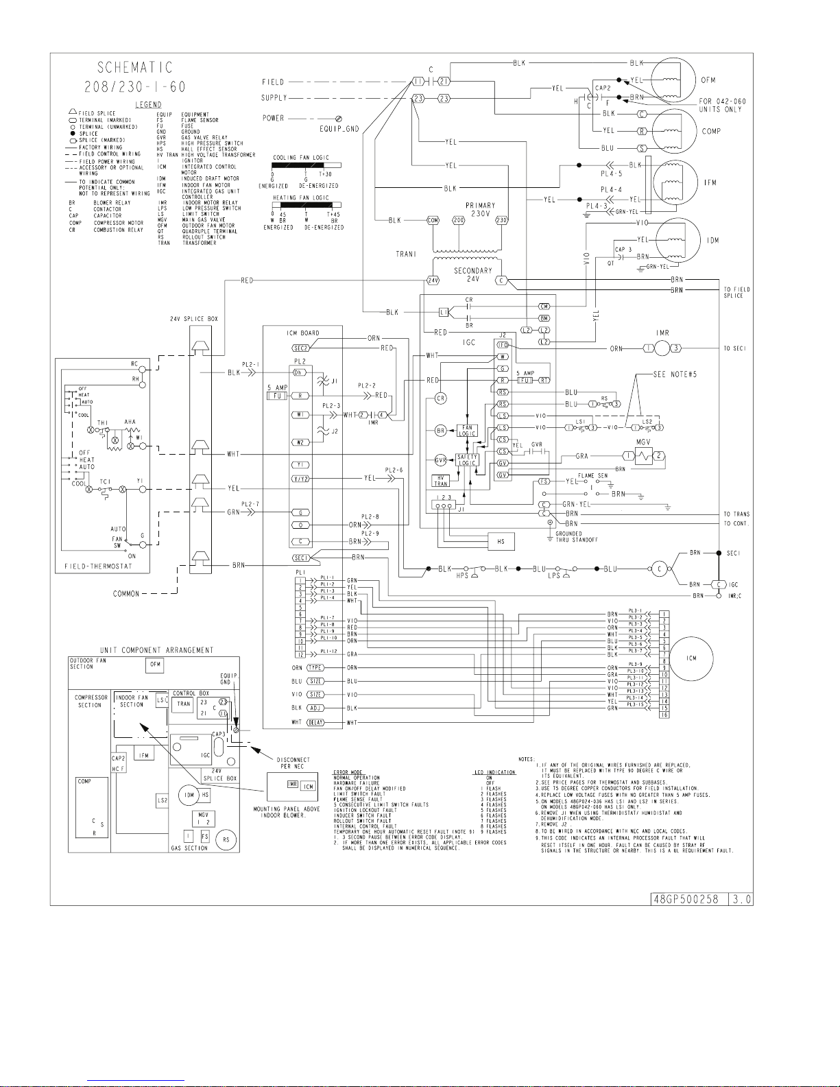
Fig. 14—ICM FIOP Electric Schematic—Unit 583B
C01035
—14—
Page 15
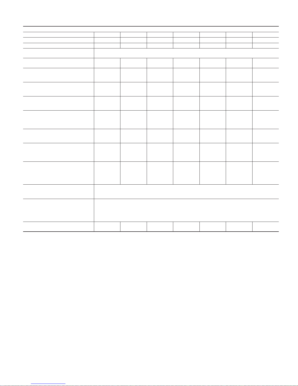
TABLE 4—ICM FIOP PHYSICAL DATA—UNIT 683B
THIS DATA APPLIES TO 683B UNITS WITH THE ICM INDOOR MOTOR FIOP
UNIT SIZE 683B 024040 030040 030060 036060 036090 042060 042090
NOMINAL CAPACITY (ton) 2 2-1/2 2-1/2 3 3 3-1/2 3-1/2
OPERATING WEIGHT (lb.) 310 324 324 321 321 380 380
COMPRESSORS
Quantity
Scroll
1
REFRIGERANT (R-410A)
Quantity (lb.)
7.0 8.9 8.9 9.3 9.3 9.5 9.5
REFRIGERANT METERING DEVICE
Orifice Indoor (in.)
Check-Flo-Rater™ Piston
0.061 0.061 0.061 0.067 0.067 0.073 0.073
REFRIGERANT METERING DEVICE
Orifice Outdoor (in.)
Check-Flo-Rater™ Piston
0.032 (2) 0.040 (2) 0.040 (2) 0.040 (2) 0.040 (2) 0.038 (2) 0.038 (2)
OUTDOOR COIL
Rows...Fins/in.
Face Area (sq ft)
2...17
8.5
2...17
10.3
2...17
10.3
2...17
10.3
2...17
10.3
2...17
13.5
2...17
13.5
OUTDOOR FAN
Nominal Cfm
Diameter (in.)
Motor Hp (Rpm)
2350
22
1/8 (825)
2350
22
1/8 (825)
2350
22
1/8 (825)
2500
22
1/4 (1100)
2500
22
1/4 (1100)
2350
22
1/8 (825)
2350
22
1/8 (825)
INDOOR COIL
Rows...Fins/in.
Face Area (sq ft)
3...15
3.7
3...15
3.7
3...15
3.7
4...15
3.7
4...15
3.7
3...15
4.7
3...15
4.7
INDOOR BLOWER
Nominal Airflow (Cfm)
Size (in.)
Motor (HP)
800
10X10
1/2
1000
10X10
1/2
1000
10X10
1/2
1200
11X10
3/4
1200
11X10
3/4
1400
11X10
3/4
1400
11X10
3/4
FURNACE SECTION*
Burner Orifice No. (Qty...Drill Size)
Natural Gas
Burner Orifice No. (Qty...Drill Size)
Propane Gas
2...44
2...50
2...44
2...50
2...38
2...46
2...38
2...46
3...38
3...46
2...38
2...46
3...38
3...46
HIGH-PRESSURE SWITCH (psig)
Cutout
Reset (Auto)
610±15
420±25
LOSS-OF-CHARGE/LOW-
PRESSURE SWITCH
(Liquid Line) (psig)
Cutout
Reset (Auto)
20±5
45±10
RETURN-AIR FILTERS (in.)
Throwaway
20X20X1 20X20X1 20X20X1 20X24X1 20X24X1 24X30X1 24X30X1
* Based on altitude of 0 to 2000 ft.
—15—
Page 16
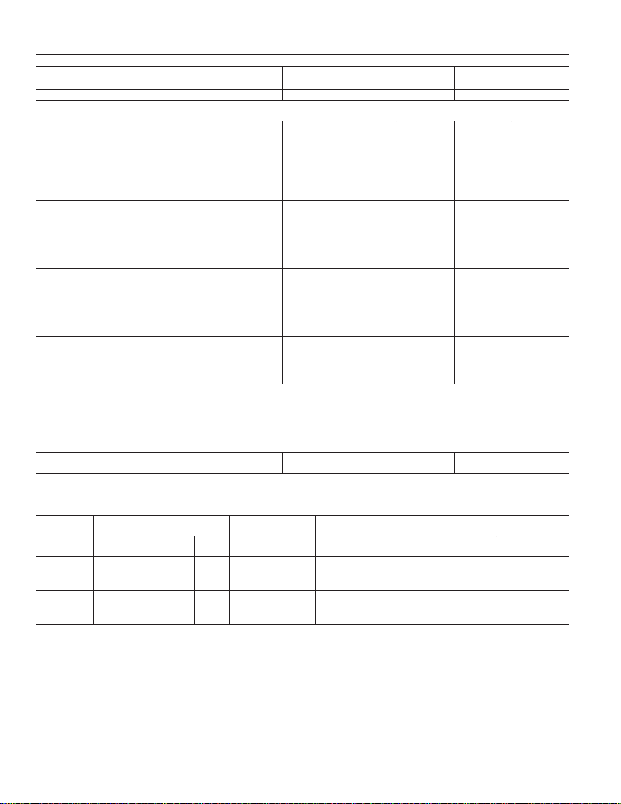
TABLE 5—ICM FIOP PHYSICAL DATA—UNIT 683B (CONTINUED)
THIS DATA APPLIES TO 683B UNITS WITH THE ICM INDOOR MOTOR FIOP
UNIT SIZE 683B 048090 048115 048130 060090 060115 060130
NOMINAL CAPACITY (ton) 444555
OPERATING WEIGHT (lb.) 409 409 409 504 504 504
COMPRESSORS
Quantity
Scroll
1
REFRIGERANT (R-410A)
Quantity (lb.)
10.6 10.6 10.6 12.4 12.4 12.4
REFRIGERANT METERING DEVICE
Orifice Indoor (in.)
Check-Flo-Rater™ Piston
.076 .076 .076 .088 .088 .088
REFRIGERANT METERING DEVICE
Orifice Outdoor (in.)
Check-Flo-Rater™ Piston
0.046 (2) 0.046 (2) 0.046 (2) 0.052 (2) 0.052 (2) 0.052 (2)
OUTDOOR COIL
Rows...Fins/in.
Face Area (sq ft)
2...17
13.5
2...17
13.5
2...17
13.5
2...17
15.4
2...17
15.4
2...17
15.4
OUTDOOR FAN
Nominal Cfm
Diameter (in.)
Motor Hp (Rpm)
3300
22
1/4 (1100)
3300
22
1/4 (1100)
3300
22
1/4 (1100)
3300
22
1/4 (1100)
3300
22
1/4 (1100)
3300
22
1/4 (1100)
INDOOR COIL
Rows...Fins/in.
Face Area (sq ft)
4...15
4.7
4...15
4.7
4...15
4.7
4...15
5.7
4...15
5.7
4...15
5.7
INDOOR BLOWER
Nominal Airflow (Cfm)
Size (in.)
Motor (HP)
1600
11X10
3/4
1600
11X10
3/4
1600
11X10
3/4
1750
11X10
1.0
1750
11X10
1.0
1750
11X10
1.0
FURNACE SECTION*
Burner Orifice No. (Qty...Drill Size)
Natural Gas
Burner Orifice No. (Qty...Drill Size)
Propane Gas
3...38
3...46
3...33
3...42
3...31
3...41
3...38
3...46
3...33
3...42
3...31
3...41
HIGH-PRESSURE SWITCH (psig)
Cutout
Reset (Auto)
610±15
420±25
LOSS-OF-CHARGE/LOW-PRESSURE SWITCH
(Liquid Line) (psig)
Cutout
Reset (Auto)
20±5
45±10
RETURN-AIR FILTERS (in.)
Throwaway
24X30X1 24X30X1 24X30X1 24X30X1 24X30X1 24X30X1
* Based on altitude of 0 to 2000 ft.
TABLE 6—683B WITH ICM FIOP ELECTRICAL DATA
UNIT
SIZE 683B
V-PH-HZ
VOLTAGE
RANGE
COMPRESSOR
OUTDOOR FAN
MOTOR
INDOOR FAN
MOTOR
POWER SUPPLY
MIN MAX RLA LRA FLA FLA MCA
MAX FUSE
OR CKT. BKR.
024 208/230–1–60 187 253 13.5 61.0 0.9 4.3 22.1 30
030 208/230–1–60 187 253 15.9 73.0 0.9 4.3 25.1 35
036 208/230–1–60 187 253 16.9 83.0 1.6 6.8 29.5 40
042 208/230–1–60 187 253 22.4 105.0 0.9 6.8 35.7 50
048 208/230–1–60 187 253 21.3 109.0 1.6 6.8 35.0 50
060 208/230–1–60 187 253 27.6 158.0 1.6 9.2 45.3 60
—16—
Page 17
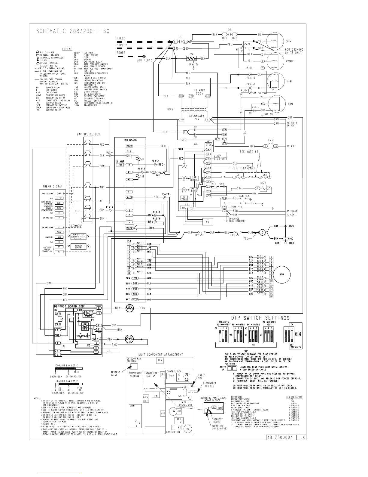
Fig. 15—ICM FIOP Electric Schematic—Unit 683B
C01101
—17—
Page 18
TABLE 7—ICM FIOP PHYSICAL DATA—UNIT 702B
THIS DATA APPLIES TO 702B UNITS WITH THE ICM INDOOR MOTOR FIOP
UNIT SIZE 024 030 036 042 048 060
NOMINAL CAPACITY (ton) 2 2-1/2 3 3-1/2 4 5
OPERATING WEIGHT (lb) 270 291 299 321 326 399
COMPRESSOR Scroll
REFRIGERANT (R-410A)
Quantity (lb)
5.0 5.5 6.9 9.0 9.5 10.0
REFRIGERANT METERING DEVICE
Orifice ID (in.)
Check-Flo-Rater™ Piston
.057 .057 .065 .070 .073 .086
CONDENSER COIL
Rows...Fins/in.
Face Area (sq. ft.)
1...17
10.9
1...17
12.7
2...17
9.1
2...17
12.3
2...17
12.3
2...17
16.4
CONDENSER FAN
Nominal Cfm
Diameter (in.)
Motor Hp (Rpm)
2350
22
1/8 (825)
2350
22
1/8 (825)
2350
22
1/8 (825)
2350
22
1/8 (825)
3300
22
1/4 (1100)
3300
22
1/4 (1100)
EVAPORATOR COIL
Rows...Fins/in.
Face Area (sq. ft.)
3...15
3.7
3...15
3.7
3...15
3.7
3...15
4.7
4...15
4.7
4...15
4.7
EVAPORATOR BLOWER
Nominal Airflow (Cfm)
Size (in.)
Motor (HP)
800
10x10
1/2
1000
10x10
1/2
1200
10x10
3/4
1400
11x10
3/4
1600
11x10
3/4
2000
11x10
1
HIGH-PRESSURE SWITCH (psig)
Cutout
Reset (Auto)
610±15
420±25
LOSS-OF-CHARGE/LOW-PRESSURE SWITCH
(Liquid Line) (psig)
Cutout
Reset (Auto)
20±5
45±10
RETURN-AIR FILTERS (in.)
Throwaway
20X20X1 20X20X1 20X24X1 24X30X1 24X30X1 24X30X1
—18—
Page 19
TABLE 8—702B WITH ICM FIOP ELECTRICAL DATA
UNIT
SIZE 702B
V-PH-HZ
VOLTAGE
RANGE
COMPRESSOR
OUTDOOR
FAN
MOTOR
INDOOR
FAN
MOTOR
ELECTRIC
HEAT
SINGLE POINT
POWER SUPPLY
MIN MAX RLA LRA FLA FLA Nominal kW* FLA MCA
MAX FUSE
OR CKT. BKR.
MOCP
024 208/230–1–60 187 253 13.5 61.0 0.9 4.3
-/-
3.8/5.0
5.4/7.2
7.5/10.0
-/-
18.1/20.8
25.9/30.0
36.1/41.7
22.1/22.1
27.9/31.4
37.8/42.9
50.5/57.5
30/30
30/35
40/50
60/60
–
–
–
–
030 208/230–1–60 187 253 14.7 73.0 0.9 4.3
-/-
3.8/5.0
5.4/7.2
7.5/10.0
-/-
18.1/20.8
25.9/30.0
36.1/41.7
23.5/23.5
27.9/31.4
37.8/42.9
50.5/57.5
30/30
30/35
40/50
60/60
–
–
–
–
036 208/230–1–60 187 253 15.4 83.0 0.9 6.8
-/-
3.8/5.0
5.4/7.2
7.5/10.0
11.3/15.0
-/-
18.1/20.8
25.9/30.0
36.1/41.7
54.2/62.5
27.0/27.0
31.1/34.5
40.9/46.0
53.6/60.6
76.2/86.6
35/35
35/40
50/50
60/–
–
–
–
–
–/70
80/90
042 208/230–1–60 187 253 18.6 105.0 0.9 6.8
-/-
3.8/5.0
5.4/7.2
7.5/10.0
11.3/15.0
15.0/20.0
-/-
18.1/20.8
25.9/30.0
36.1/41.7
54.2/62.5
72.2/83.3
31.0/31.0
31.1/34.5
40.9/46.0
53.6/60.6
76.2/86.6
98.8/112.7
40/10
40/40
50/50
60/–
–
–
–
–
–
–/70
90/90
100/125
048 208/230–1–60 187 253 20.5 109.0 1.6 6.8
-/-
3.8/5.0
5.4/7.2
7.5/10.0
11.3/15.0
15.0/20.0
-/-
18.1/20.8
25.9/30.0
36.1/41.7
54.2/62.5
72.2/83.3
34.0/34.0
34.0/34.5
40.9/46.0
53.6/60.6
76.2/86.6
98.8/112.7
40/40
40/40
50/50
60/-
–
–
–
–
–
–/70
90/90
100/125
060 208/230–1–60 187 253 27.6 158.0 1.6 9.1
-/-
3.8/5.0
5.4/7.2
7.5/10.0
11.3/15.0
15.0/20.0
-/-
18.1/20.8
25.9/30.0
36.1/41.7
54.2/62.5
72.2/83.3
45.2/45.2
45.2/45.2
43.8/48.9
56.5/63.5
79.1/89.5
101.6/115.5
60/60
60/60
50/50
60/-
–
–
–
–
–
–/70
90/90
110/125
* Heater capacity (kW) based on heater voltage of 208-v & 240-v. If power distribution voltage to unit varies from rated heater voltage, heater kW will vary accordingly. Refer
to
Multiplication Factors
Table 23.
—19—
Page 20
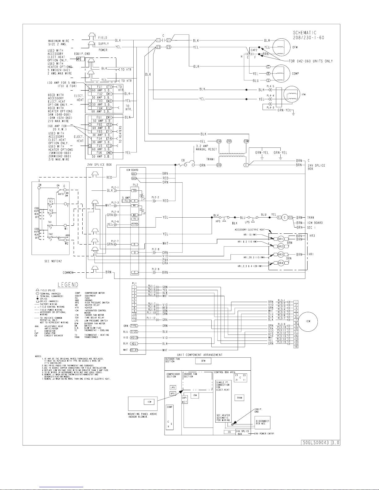
Fig. 16—ICM FIOP Electrical Schematic—702B
C01037
—20—
Page 21
TABLE 9—ICM FIOP PHYSICAL DATA—UNIT 602B
THIS DATA APPLIES TO 602B UNITS WITH THE ICM INDOOR MOTOR FIOP
UNIT SIZE 602B024 602B030 602B036 602B042 602B048 602B060
NOMINAL CAPACITY (ton) 2 2-1/2 3 3-1/2 4 5
OPERATING WEIGHT (lb.) 299 320 328 350 355 428
COMPRESSOR QUANTITY 1
TYPE SCROLL COMPRESSOR
REFRIGERANT R-410A
REFRIGERANT METERING DEVICE Check-Flo-Rater™
Refrigerant (R-410A) Quantity (lb.) 7.0 8.9 9.3 9.5 10.6 12.4
ORIFICE ID (in.) 0.061 0.061 0.067 0.073 0.076 0.088
ORIFICE OD (in.) 0.032 (2) 0.040 (2) 0.040 (2) 0.038 (2) 0.046 (2) 0.052 (2)
OUTDOOR COIL
Rows... Fins/in.
face area (sq. ft.)
2...17
8.5
2...17
10.3
2...17
10.3
2...17
13.5
2...17
13.5
2...17
15.4
OUTDOOR FAN
Nominal Airflow (CFM)
Diameter
Motor HP (RPM)
2350
22
1/8 (825)
2350
22
1/8 (825)
2800
22
1/4 (1100)
2500
22
1/8 (825)
3300
22
1/4 (1100)
3300
22
1/4 (1100)
INDOOR COIL
Rows... Fins/in.
face area (sq. ft.)
3...15
3.7
3...15
3.7
4...15
3.7
3...15
4.7
4...15
4.7
4...15
5.7
INDOOR BLOWER
Nominal Airflow (CFM)
Size (in.)
Motor (HP)
800
10X10
1/2
1000
10X10
1/2
1200
10X10
3/4
1400
11X10
3/4
1600
11X10
3/4
2000
11X10
1
HIGH-PRESSURE SWITCH (psig)
Cutout
Reset (Auto)
610±15
420±25
LOSS-OF-CHARGE/LOW-PRESSURE SWITCH
(Liquid Line) (psig)
Cutout
Reset (Auto)
20±5
45±10
RETURN-AIR FILTERS (in.)
throwaway
20X20X1 20X20X1 20X24X1 24X30X1 24X30X1 24X30X1
—21—
Page 22
TABLE 10—602B WITH ICM FIOP ELECTRICAL DATA
UNIT
SIZE 602B
V-PH-HZ
VOLTAGE
RANGE
COMPRESSOR
OUTDOOR
FAN
MOTOR
INDOOR
FAN
MOTOR
ELECTRIC
HEAT
SINGLE POINT
POWER SUPPLY
MIN MAX RLA LRA FLA FLA Nominal kW* FLA MCA
MAX FUSE
OR CKT. BKR.
MOCP
024 208/230–1–60 187 253 13.5 61.0 0.9 4.3
-/-
3.8/5.0
5.4/7.2
7.5/10.0
-/-
18.1/20.8
25.9/30.0
36.1/41.7
22.1/22.1
44.6/48.1
54.5/59.6
67.2/74.2
30/30
50/50
60/–
–
–
–
–/70
70/80
030 208/230–1–60 187 253 15.9 73.0 0.9 4.3
-/-
3.8/5.0
5.4/7.2
7.5/10.0
11.3/15.0
-/-
18.1/20.8
25.9/30.0
36.1/41.7
54.2/62.5
25.1/25.1
47.6/51.1
57.4/62.6
70.2/77.2
92.8/103.2
30/30
60/60
–
–
–
–
–
70/70
80/80
100/110
036 208/230–1–60 187 253 16.9 83.0 1.6 6.8
-/-
3.8/5.0
5.4/7.2
7.5/10.0
11.3/15.0
-/-
18.1/20.8
25.9/30.0
36.1/41.7
54.2/62.5
29.5/29.5
52.1/55.6
61.9/67.0
74.7/81.6
97.2/107.7
40/40
60/60
–
–
–
–
–
70/80
80/90
100/110
042 208/230–1–60 187 253 22.4 105.0 0.9 6.8
-/-
3.8/5.0
5.4/7.2
7.5/10.0
11.3/15.0
15.0/20.0
-/-
18.1/20.8
25.9/30.0
36.1/41.7
54.2/62.5
72.2/83.3
35.7/35.7
58.3/61.7
68.1/73.2
80.8/87.8
103.4/113.0
126.0/139.9
50/50
–
–
–
–
–
–
70/70
80/80
90/90
110/125
150/150
048 208/230–1–60 187 253 21.3 109.0 1.6 6.8
-/-
3.8/5.0
5.4/7.2
7.5/10.0
11.3/15.0
15.0/20.0
-/-
18.1/20.8
25.9/30.0
36.1/41.7
54.2/62.5
72.2/83.3
35.0/35.0
57.6/61.1
67.4/72.5
80.2/87.1
102.7/113.2
125.3/139.2
50/50
–
–
–
–
–
–
70/70
80/80
90/90
110/125
150/150
060 208/230–1–60 187 253 27.6 158.0 1.6 9.2
-/-
3.8/5.0
5.4/7.2
7.5/10.0
11.3/15.0
15.0/20.0
-/-
18.1/20.8
25.9/30.0
36.1/41.7
54.2/62.5
72.2/83.3
45.1/45.1
67.7/71.1
77.7/82.8
90.2/97.2
112.8/123.2
135.4/149.3
60/60
–
–
–
–
–
–
80/80
90/90
100/110
125/125
150/150
* Heater capacity (kW) based on heater voltage of 208-v & 240-v. If power distribution voltage to unit varies from rated heater voltage, heater kW will vary accordingly. Refer
to
Multiplication Factors
Table 23.
—22—
Page 23
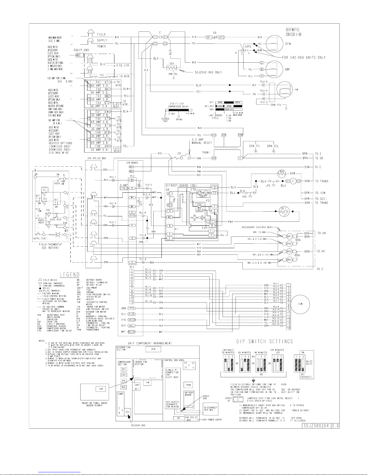
Fig. 17—ICM FIOP Electrical Schematic—602B
c01036
—23—
Page 24
TABLE 11–583B & 683B COOLING (AND HEAT PUMP HEATING-683B ONLY)
DRY COIL ICM AIRFLOW
SMALL CABINET
UNIT
SIZE
CFM ADJUST
PIN SELECT
LO PIN NOM PIN HI PIN
EXTERNAL STATIC
PRESSURE RANGE
0.0–0.4 0.4–0.7 0.7–1.0 0.0–0.4 0.4–0.7 0.7–1.0 0.0–0.4 0.4–0.7 0.7–1.0
024
COOLING † 745 675 – 835 750 690 940 880 815
COOLING
DEHUMIDIFY
675 625 – 675 650 600 755 730 705
HEAT PUMP
COMFORT (683B Only)
670 605 – 740 690 635 845 795 735
030
COOLING † 940 860 785 1020 965 895 1185 1100 1010
COOLING
DEHUMIDIFY
820 785 735 820 800 770 955 920 880
HEAT PUMP
COMFORT (683B Only)
850 780 745 935 905 845 1055 1040 955
036
COOLING † 1025 935 – 1145 1085 1005 1320 1260 1180
COOLING
DEHUMIDIFY
925 885 – 925 900 870 1060 1040 1010
HEAT PUMP
COMFORT (683B Only)
955 880 – 1075 990 920 1220 1180 1125
† On 683B Only
Heat Pump Efficiency
and
Cooling
pin selections deliver equal airflow
TABLE 12—583B & 683B COOLING (AND HEAT PUMP HEATING-683B ONLY)
DRY COIL ICM AIRFLOW
LARGE CABINET
UNIT
SIZE
CFM ADJUST
PIN SELECT
LO PIN NOM PIN HI PIN
EXTERNAL STATIC
PRESSURE RANGE
0.1–1.0 0.1–1.0 0.1–1.0
042
COOLING † 1100 1225 1410
COOLING
DEHUMIDIFY
980 980 1125
HEAT PUMP
COMFORT (683B Only)
990 1100 1265
048
COOLING † 1260 1400 1610
COOLING
DEHUMIDIFY
1120 1120 1290
HEAT PUMP
COMFORT (683B Only)
1135 1260 1450
060
COOLING † 1575 1750 2010
COOLING
DEHUMIDIFY
1400 1400 1610
HEAT PUMP
COMFORT (683B Only)
1415 1575 1810
† On 683B Only
Heat Pump Efficiency
and
Cooling
pin selections deliver equal airflow
TABLE 13—583B & 683B GAS HEATING ICM AIRFLOW
SMALL CABINET
EASY SELECT™
BOARD SETTING (CFM)
700 800 1100 1250
Unit
Size
External
Static
Pressure
0.0–0.4 0.4–0.7 0.7–1.0 0.0–0.4 0.4–0.7 0.7–1.0 0.0–0.4 0.4–0.7 0.7–1.0 0.0–0.4 0.4–0.7 0.7–1.0
Gas Heat Size
024
040 –––855770710––––––
060 ––––––1020 890 835 – – –
030
040 –––880840805––––––
060 ––––––1030 970 910 – – –
036
060 ––––––1035 995 955 – – –
090 –––––––––1170 1110 1025
—24—
Page 25
TABLE 14—583B & 683B GAS HEATING ICM AIRFLOW
LARGE CABINET
EASY SELECT™
BOARD SETTING (CFM)
1000 1250 1600 1750 1800
Unit
Size
External
Static
Pressure
0.0–1.0 0.0–1.0 0.0–1.0 0.0–1.0 0.0–1.0
Gas Heat Size
042
060 1000 ––––
090 – 1250 – – –
048
090 – 1250 – – –
115 – – 1600 – –
130 – – – 1750 –
060
090 – 1250 – – –
115 – – 1600 – –
130 ––––1800
TABLE 15—583B & 683B ICM AIR FLOW VS. TEMPERATURE RISE CHART
UNIT
COOLING
SIZE
RATED GAS
INPUT RATE
(X 1000)
AIRFLOW SETTING
EASY SELECT™
(SCFM)
CALCULATED
TEMPERATURE
RISE
MIN.
TEMP
RISE
MAX
TEMP
RISE
MAX
DISCH.
TEMP
583B
&
683B
024
40 800 36.5 20 50 175
60
(583B Only)
1100 40 35 65 165
030
40 800 36.5 20 50 175
60 1100 40 35 65 165
036
60 1100 40 25 55 165
90 1200 54 45 75 175
042
60 1000 44 20 50 165
90 1250 53 35 65 170
048
90 1250 53 25 55 165
115 1600 53 35 65 170
130 1750 54 40 70 175
060
90 1600 41 25 55 155
115 1600 53 35 65 170
130 1800 53 40 70 175
TABLE 16—702B/602B COOLING & HEATING DRY COIL ICM AIRFLOW
SMALL CABINET
UNIT
SIZE
CFM ADJUST
PIN SELECT
LO PIN NOM PIN HI PIN
EXTERNAL STATIC
PRESSURE RANGE
0.0–0.4 0.4–0.7 0.7–1.0 0.0–0.4 0.4–0.7 0.7–1.0 0.0–0.4 0.4–0.7 0.7–1.0
024
COOLING † 800 725 – 885 805 730 990 930 855
COOLING
DEHUMIDIFY
715 670 – 715 695 645 795 775 745
HEAT PUMP
COMFORT (602B Only)
720 660 – 790 745 685 890 850 785
030
COOLING † 1010 920 825 1105 1030 930 1255 1160 1050
COOLING
DEHUMIDIFY
890 845 795 890 865 825 1010 980 925
HEAT PUMP
COMFORT (602B Only)
945 850 765 1020 965 895 1140 1105 995
036
COOLING † 1110 1025 970 1235 1175 1115 1400 1355 1280
COOLING
DEHUMIDIFY
990 960 910 990 975 940 1125 1110 1085
HEAT PUMP
COMFORT (602B Only)
1035 975 910 1160 1080 1020 1305 1275 1220
†
Heat Pump Efficiency
and
Cooling
pin selections deliver equal airflow
—25—
Page 26
TABLE 17—702B/602B COOLING & HEATING DRY COIL ICM AIRFLOW
LARGE CABINET
UNIT
SIZE
CFM ADJUST
PIN SELECT
LO PIN NOM PIN HI PIN
EXTERNAL STATIC
PRESSURE RANGE
0.1–1.0 0.1–1.0 0.1–1.0
042
COOLING † 1100 1225 1410
COOLING
DEHUMIDIFY
980 980 1125
HEAT PUMP
COMFORT (602B Only)
990 1100 1265
048
COOLING † 1260 1400 1610
COOLING
DEHUMIDIFY
1120 1120 1290
HEAT PUMP
COMFORT (602B Only)
1135 1260 1450
060
COOLING † 1575 1750 2010
COOLING
DEHUMIDIFY
1400 1400 1610
HEAT PUMP
COMFORT (602B Only)
1415 1575 1810
†
Heat Pump Efficiency
and
Cooling
pin selections deliver equal airflow
TABLE 18—MINIMUM AIRFLOW FOR RELIABLE ELECTRIC HEATER OPERATION (CFM)
UNIT
SIZE
024 030 036 042 048 060
602B 750 1025 1250 1285 1710 1800
702B 750 750 1250 1205 1500 1800
TABLE 19—ELECTRIC HEAT PRESSURE DROP TABLE (IN. WG)
SMALL CABINET
STATIC
CFM
500 600 700 800 900 1000 1100 1200 1300 1400 1500 1600
5kW 0.00 0.00 0.00 0.00 0.00 0.00 0.00 0.00 0.02 0.04 0.06 0.07
7.5 kW 0.00 0.00 0.00 0.00 0.00 0.00 0.02 0.03 0.05 0.07 0.08 0.09
10 kW 0.00 0.00 0.00 0.00 0.00 0.02 0.04 0.06 0.07 0.09 0.10 0.11
15 kW 0.00 0.00 0.00 0.02 0.04 0.06 0.08 0.10 0.12 0.14 0.16 0.18
20 kW 0.00 0.00 0.02 0.04 0.06 0.08 0.09 0.11 0.13 0.15 0.17 0.19
TABLE 20— ELECTRIC HEAT PRESSURE DROP TABLE (IN. WG)
LARGE CABINET
STATIC
CFM
1100 1200 1300 1400 1500 1600 1700 1800 1900 2000 2100 2200 2300 2400 2500
5kW 0.00 0.00 0.00 0.01 0.02 0.03 0.04 0.05 0.06 0.07 0.08 0.09 0.10 0.11 0.12
7.5 kW 0.00 0.00 0.01 0.02 0.03 0.04 0.05 0.06 0.07 0.08 0.09 0.10 0.11 0.12 0.13
10 kW 0.00 0.00 0.01 0.02 0.03 0.04 0.05 0.06 0.07 0.08 0.09 0.10 0.11 0.12 0.13
15 kW 0.00 0.02 0.03 0.04 0.05 0.06 0.07 0.08 0.09 0.10 0.11 0.12 0.13 0.14 0.15
20 kW 0.02 0.03 0.04 0.05 0.06 0.07 0.08 0.09 0.10 0.11 0.12 0.13 0.14 0.15 0.16
—26—
Page 27
TABLE 21—ICM FIOP WET COIL PRESSURE DROP (IN. WG)
UNIT
SIZE
STANDARD CFM (SCFM)
600 700 800 900 1000 1100 1200 1300 1400 1500 1600 1700 1800 1900 2000 2100
024 0.005 0.007 0.010 0.012 0.015 –––––––––––
030 – 0.007 0.010 0.012 0.015 0.018 0.021 0.024 ––––––––
036 – – – 0.019 0.023 0.027 0.032 0.037 0.042 0.047 ––––––
042 ––––0.014 0.017 0.020 0.024 0.027 0.031 0.035 0.039 0.043 – – –
048 ––––––0.027 0.032 0.036 0.041 0.046 0.052 0.057 0.063 0.068 –
060 –––––––––0.029 0.032 0.036 0.040 0.045 0.049 0.053
TABLE 22—FILTER PRESSURE DROP TABLE (IN. WG)
FILTER SIZE
CFM
500 600 700 800 900 1000 1100 1200 1300 1400 1500 1600 1700 1800 1900 2000 2100 2200 2300
20X20X1 0.05 0.07 0.08 0.10 0.12 0.13 0.14 0.15 ———————————
20X24X1 ————0.09 0.10 0.11 0.13 0.14 0.15 0.16 ————————
24X30X1 —————— —0.07 0.08 0.09 0.10 0.11 0.12 0.13 0.14 0.15 0.16 0.17 0.18
TABLE 23—ELECTRIC HEATER MULTIPLICATION FACTORS
HEATER KW
RATING
VOLTAGE
DISTRIBUTION
MULTIPLICATION
FACTOR
240
200 .69
208 .75
230 .92
240 1.00
Example:
15.0 kW (at 240-v.) heater on 208-v.
= 15.0 (.75 mult. factor)
= 11.25 capacity at 208-v.
—27—
Page 28
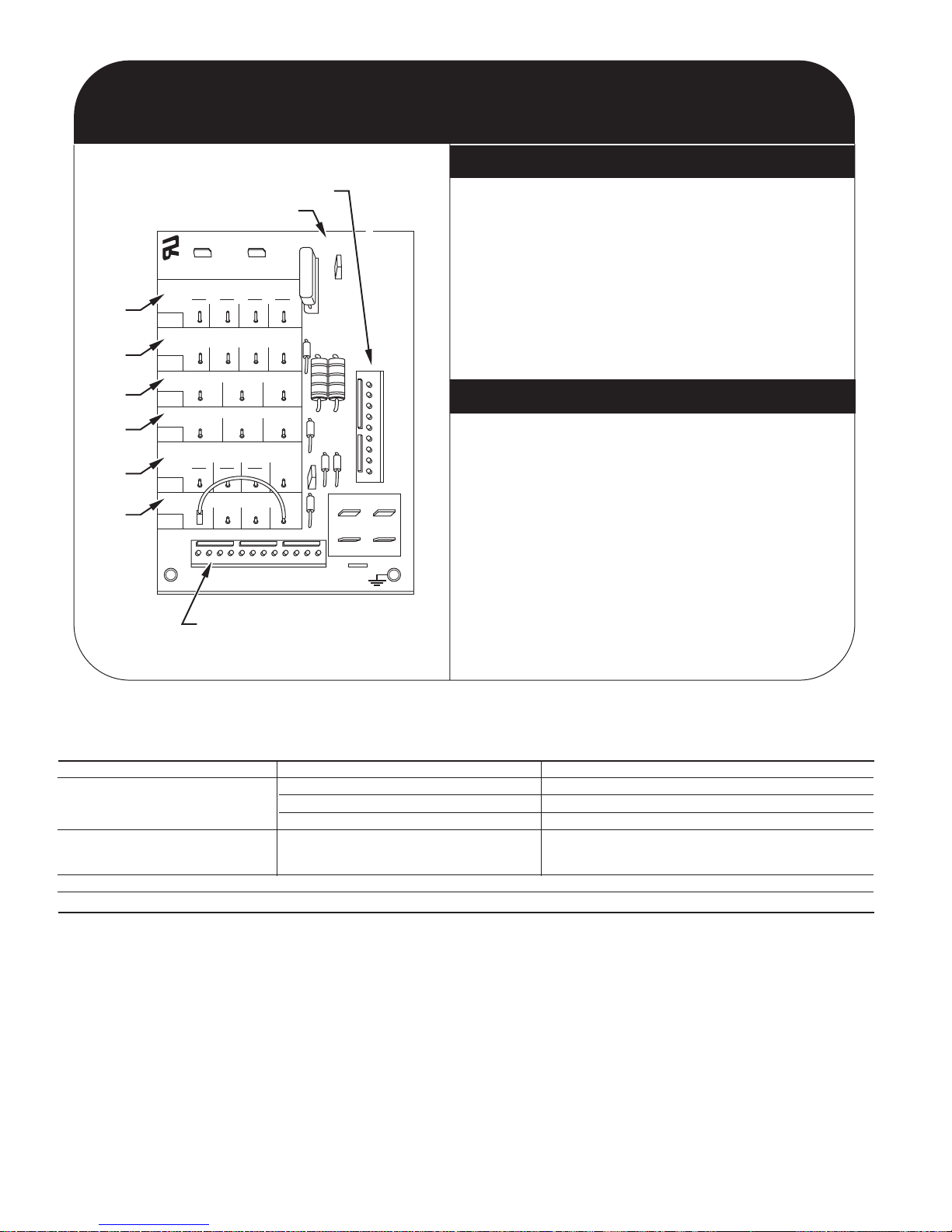
ICM QUICK REFERENCE GUIDE
c01034
EASY SELECT
HEATER/MOTOR
AUX HEAT KW/CFM
0-30
1075
SEC1 SEC2
J1
AC/HP SIZE
036 030 024 018
AC
HP-COMFORT
HP-EFF
NOM HI
ENH
LO
SYSTEM TYPE
AC/HP CFM ADJUST
ON/OFF DELAY
CONTINUOUS FAN
MED HI YELLO
AUX1 HUM1
AUX2
24VAC
GRY
HUM2
YEL
WHT
BLK
ORN
BLU
VIO
0-20
875
0-10
725
09030900
0
0-5
625
TM
J2
D
H
R
W
1
W
2
Y
1
Y/Y
2
G
O
C
QUICK REFERENCE GUIDE
SET-UP INSTRUCTIONS FOR WARMER HEATING TEMPERATURES
AND SUPER HUMIDITY CONTROL IN COOLING
A. AUX HEAT - Set for heater size (Ex: 0-10 for 10 kw)
B. AC/HP SIZE - Set for size of outdoor unit
C. SYSTEM TYPE - Select "HP COMFORT"
D. AC/HP CFM ADJUST - Select "LO"
E. ON/OFF DELAY - Select "ENH"
F. CONTINUOUS FAN - Select desired speed
2. Remove Jumper J1 to activate all dehumidify modes.
3. Complete wiring and install outdoor temperature sensor
according to Installation Instructions.
1. Configuration Taps
(See Installation Instructions, for detailed description.)
• Option 5 (Variable Speed Motors) - set to ON
• Option 7 (Super Dehumidify) - set to ON
• Option 12 (Heaters during Defrost) - setting "2" is
suggested for all heaters
• Option 16 - Heat pump systems set to ON for warmer heat
below 40° F.
• Option 17 - Select programmable or non-programmable mode.
2. Thermidistat Control Configurations
(See Thermidistat™ Control Installation Instructions for
detailed description.)
3. Set desired humidity level on front of Thermidistat
(50 to 55% RH recommended). For dehumidification in
cooling, both "dhu" and "cool" must be displayed.
1. Set "DIP Switches" - Set the dip switches (back of Thermidistat
Control Board) appropriately for specific system being installed.
EASY SELECT BOARD
THERMIDISTAT™ CONTROL SETTINGS
9 PIN CONNECTOR
ICM PRINTED CIRCUIT BOARD
12 PIN CONNECTOR
A
B
C
D
E
F
TABLE 24—TROUBLESHOOTING CHART
SYSTEM CAUSE REMEDY
IFM does not run
Blower wheel not secured to shaft Inspect and properly tighten blower wheel to shaft
Insufficient voltage at motor Determine cause and correct
Power connectors not properly seated Connectors should snap easily; do not force
IFMoperationisintermittentConnectorsnotfirmlyseated
Gently pull wires individually
tobesuretheyareinserted
intotheconnectors
—28—
Page 29
c01999
START-UP CHECKLIST
(Remove and Store in Job File)
I. Preliminar y Information
MODEL NO.:_________________________________
SERIAL NO.:__________________________________
DATE:_______________________________________
TECHNICIAN:_________________________________
II. PRE-START-UP (Inser t checkmark in box as each item is completed)
( ) VERIFY THAT ALL PACKING MATERIALS HAVE BEEN REMOVED FROM UNIT
( ) REMOVE ALL SHIPPING HOLD DOWN BOLTS AND BRACKETS PER INSTALLATION INSTRUCTIONS
( ) CHECK ALL ELECTRICAL CONNECTIONS AND TERMINALS FOR TIGHTNESS
( ) CHECK GAS PIPING FOR LEAKS (WHERE APPLICABLE)
( ) CHECK THAT INDOOR (EVAPORATOR) AIR FILTER IS CLEAN AND IN PLACE
( ) VERIFY THAT UNIT INSTALLATION IS LEVEL
( ) CHECK FAN WHEEL, AND PROPELLER FOR LOCATION IN HOUSING/ORIFICE AND SETSCREW TIGHTNESS
( ) MAKE SURE THAT - ON 060 SIZE PURON HEATPUMP, ONLY-THE TWO WIRE TIES FASTEN TO THE
OUTDOOR COILS AND REVERSING VALVE/ACCUMULATOR HAVE BEEN REMOVED.
III. START-UP
ELECTRICAL
SUPPLY VOLTAGE __________________________________
COMPRESSOR AMPS_________________________________
INDOOR (EVAPORATOR) FAN AMPS___________
TEMPERATURES
OUTDOOR (CONDENSER) AIR TEMPERATURE ___________DB
RETURN-AIR TEMPERATURE ___________DB ___________WB
COOLING SUPPLY AIR ___________DB ___________WB
HEAT PUMP SUPPLY AIR ___________
GAS HEAT SUPPLY AIR ___________
ELECTRIC HEAT SUPPLY AIR ___________
PRESSURES
GAS INLET PRESSURE ___________IN. WG
GAS MANIFOLD PRESSURE ___________IN.WG
REFRIGERANT SUCTION ___________PSIG SUCTION LINE TEMP*___________
REFRIGERANT DISCHARGE ___________PSIG DISCHARGE TEMP†___________
( ) VERIFY REFRIGERANT CHARGE USING CHARGING CHARTS
GAS HEAT TEMPERATURE RISE
TEMPERATURE RISE (LITERATURE) RANGE___________
MEASURED TEMPERATURE RISE___________
*Measured at suction inlet to compressor
†Measured at liquid line leaving condenser.
IV. EASY SELECT SETTINGS
FULL UNIT MODEL NUMBER:___________
ENTER AVAILABLE HEATSETTINGS
ENTER AVAILABLE AIRFLOW HEAT AIR PIN CONNECTION
SETTING___________
ENTER AVAILABLE SIZES SIZE PIN CONNECTION SETTING___________
TYPE PIN CONNECTION SETTING___________
ADJUST PIN CONNECTION SETTING___________
DELAY PIN CONNECTION SETTING___________
(0/0 or 0/90 for gas/electric models)
CONTINOUS FAN PIN CONNECTION SETTING___________
EASY SELECT
Heat Settings
AC HP Size
System Type
AC HP-Comfort HP.Eff
AC/HP CFM Adjust
Norm Lo Hi
On/Off Delay
0
⁄90
30
⁄90
0
⁄0 ENH
Continous Fan
Lo Med Hi
—29—
Page 30

© 2001 Bryant Heating & Cooling Systems 7310 W. Morris St. Indianapolis, IN 46231
—30—
Printed in U.S.A. ii583b243 Catalog No. 5358-308
 Loading...