

Page 1
installation and
start-up instructions
11, 12, 13, 14 SEER
SPLIT-SYSTEM AIR CONDITIONERS
WITH PURON® REFRIGERANT
NOTE: Read the entire instruction manual before starting the
installation.
This symbol → indicates a change since the last issue.
SAFETY CONSIDERATIONS
Improper installation, adjustment, alteration, service, maintenance,
or use can cause explosion, fire, electrical shock, or other
conditions which may cause death, personal injury, or property
damage. Consult a qualified installer, service agency, or your
distributor or branch for information or assistance. The qualified
installer or agency must use factory-authorized kits or accessories
when modifying this product. Refer to the individual instructions
packaged with the kits or accessories when installing.
Follow all safety codes. Wear safety glasses, protective clothing,
and work gloves. Use quenching cloth for brazing operations.
Have fire extinguisher available. Read these instructions thoroughly and follow all warnings or cautions included in literature
and attached to the unit. Consult local building codes and National
Electrical Code (NEC) for special requirements.
Recognize safety information. This is the safety-alert symbol
When you see this symbol on the unit and in instructions or
manuals, be alert to the potential for personal injury.
Understand these signal words; DANGER, WARNING, and
CAUTION. These words are used with the safety-alert symbol.
DANGER identifies the most serious hazards which will result in
severe personal injury or death. WARNING signifies hazards
which could result in personal injury or death. CAUTION is used
to identify unsafe practices which would result in minor personal
injury or product and property damage. NOTE is used to highlight
suggestions which will result in enhanced installation, reliability,
or operation.
WARNING: Before installing, modifying, or servicing
system, main electrical disconnect switch must be in the
OFF position. There may be more than 1 disconnect
switch. Lock out and tag switch with a suitable warning
label. Electrical shock can cause personal injury or death.
CAUTION: Puron® systems operate at higher pressures
than standard R-22 systems. To avoid damage to the unit
or possible personal injury, do not use R-22 service
equipment or components on Puron® equipment.
INSTALLATION RECOMMENDATIONS
NOTE: In some cases noise in the living area has been traced to
gas pulsations from improper installation of equipment.
1. Locate unit away from windows, patios, decks, etc. where
unit operation sound may disturb customer.
2. Ensure that vapor and liquid tube diameters are appropriate
to capacity of unit.
3. Run refrigerant tubes as directly as possible by avoiding
unnecessary turns and bends.
591B, 550A
552A, 556A
Cancels: II 550A-18-3 II 550A-18-4
11-03
.
A98515
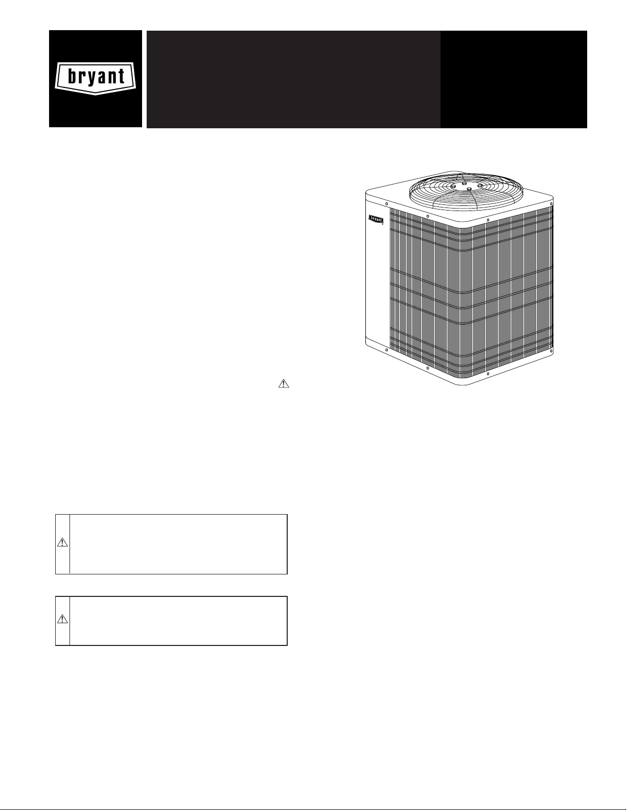
Fig. 1—Models 591B, 550A, 552A, and 556A
4. Leave some slack between structure and unit to absorb
vibration.
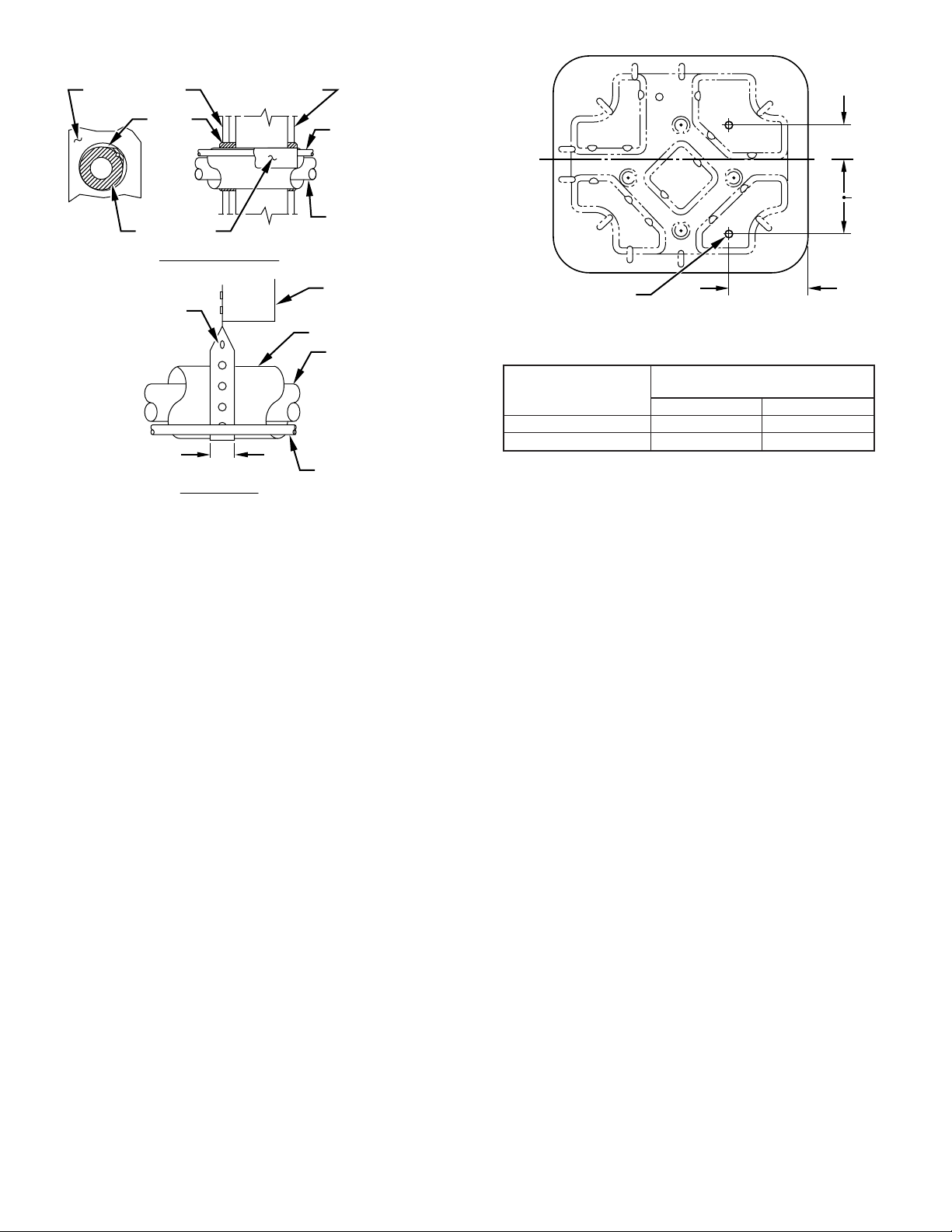
5. When passing refrigerant tubes through the wall, seal
opening with RTV or other pliablesilicon-basedcaulk. (See
Fig. 2.)
6. Avoid direct tubing contact with water pipes, duct work,
floor joists, wall studs, floors, and walls.
7. Do not suspend refrigerant tubing from joists and studs with
a rigid wire or strap which comes in direct contact with
tubing. (See Fig. 2.)
8. Ensure that tubing insulation is pliable and completely
surrounds vapor tube.
9. When necessary, use hanger straps which are 1 in. wide and
conform to shape of tubing insulation. (See Fig. 2.)
10. Isolate hanger straps from insulation by using metal sleeves
bent to conform to shape of insulation.
When outdoor unit is connected to factory-approved indoor unit,
outdoor unit contains system refrigerant charge for operation with
ARI rated indoor unit when connected by 15 ft of field-supplied or
factory accessory tubing. For proper unit operation, check refrigerant charge using charging information located on control box
cover and/or in the Check Charge section of this instruction.
IMPORTANT: Maximum liquid-line size is 3/8-in. O.D. for all
residential applications including long line.
IMPORTANT: Always install the factory-supplied liquid-line
filter drier. If replacing the filter drier, refer to Product Data Sheet
for appropriate part number. Obtain replacement filter driers from
your distributor or branch.
INSTALLATION
Specifications for this unit in residential new construction market
require the outdoor unit, indoor unit, refrigerant tubing sets,
metering device, and filter drier listed in presale literature. There
—1—
Page 2
Avoid contact between tubing and structureNOTE:
OUTDOOR WALL INDOOR WALL
CAULK
INSULATION
THROUGH THE WALL
HANGER STRAP
(AROUND VAPOR
TUBE ONLY)
1″ MIN.
SUSPENSION
LIQUID TUBE
VAPOR TUBE
JOIST
INSULATION
VAPOR TUBE
LIQUID TUBE
A94028
Fig. 2—Connecting Tubing Installation
can be no deviation. Consult the Application Guideline and
Service Manual—Air Conditioners and Heat Pumps Using Puron® Refrigerant to obtain required unit changes for specific
applications and for R-22 retrofit.
I. CHECK EQUIPMENT AND JOB SITE
A. UNPACK UNIT
Move to final location. Remove carton taking care not to damage
unit.
B. INSPECT EQUIPMENT
File claim with shipping company prior to installation if shipment
is damaged or incomplete. Locate unit rating plate on unit corner
panel. It contains information needed to properly install unit.
Check rating plate to be sure unit matches job specifications.
II. INSTALL ON A SOLID, LEVEL MOUNTING PAD
If conditions or local codes require the unit be attached to pad, tie
down bolts should be used and fastened through knockouts
provided in unit base pan. Refer to unit mounting pattern in Fig. 3
to determine base pan size and knockout hole location.
On rooftop applications, mount on level platform or frame. Place
unit above a load-bearing wall and isolate unit and tubing set from
structure. Arrange supporting members to adequately support unit
and minimize transmission of vibration to building. Consult local
codes governing rooftop applications.
Roof mounted units exposed to winds above 5 mph may require
wind baffles. Consult the Application Guideline and Service
Manual—Air Conditioner with Puron® Refrigerant for wind
baffle construction.
NOTE: Unit must be level to within ±2° (±3/8 in./ft) per
compressor manufacturer specifications.
III. CLEARANCE REQUIREMENTS
When installing, allow sufficient space for airflow clearance,
wiring, refrigerant piping, and service. Allow 30-in. clearance to
service end of unit and 48 in. above unit. For proper airflow, a 6-in.
C
3
⁄8 IN. DIA TIEDOWN
KNOCKOUTS
(2) PLACES
IN BASEPAN
DIMENSIONS (IN.)
UNIT BASE PAN
DIMENSIONS
22-1/2 X 27-1/2 2-13/16 6-15/16
30X33 5-1/16 9-11/16
TIEDOWN KNOCKOUT
AB
Fig. 3—Clearance Requirements
clearance on 1 side of unit and 12 in. on all remaining sides must
be maintained. Maintain a distance of 24 in. between units.
Position so water, snow, or ice from roof or eaves cannot fall
directly on unit.
On rooftop applications, locate unit at least 6 in. above roof
surface.
IV. OPERATING AMBIENT
The minimum outdoor operating ambient in cooling mode is 55°F,
and the maximum outdoor operating ambient in cooling mode is
125°F.
→
V. CHECK INDOOR CHECK-FLO-RATER® PISTON
AND INSTALL PISTON RING [STANDARD ON 591B, 550A
(024-048 AND 060-G), AND 552A]
If unit is to be installed with a piston metering device, proceed as
follows:
1. Check indoor coil piston to see if it matches the required
piston shown on outdoor unit rating plate. If it does not
match, replace indoor coil piston with piston shipped with
outdoor unit. The piston shipped with outdoor unit is correct
for any approved indoor coil combination.
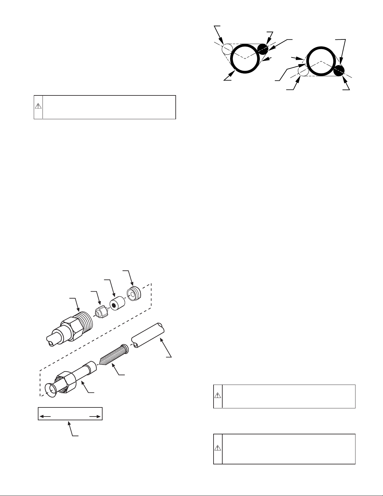
2. After correct piston is installed, locate neoprene piston ring
shipped in piston bag. Install piston ring behind metering
piston as shown in Fig. 4. The piston ring ensures that
piston stays seated during all operating conditions.
→
VI. INSTALL TXV
NOTE: ALL 556A and 550A060-H UNITS MUST BE IN-
STALLED WITH A HARD SHUT OFF PURON TXV.
The thermostatic expansion valve is specifically designed to
operate with Puron®. Do not use an R-22 TXV. An existing R-22
TXV must be replaced with a factory-approved TXV specifically
designed for Puron®.
NOTE: FK4 and FC4 fan coils are equipped with an R-22 TXV.
If an FK4 or an FC4 fan coil is used with a Puron® air conditioner,
the R-22 TXV must be replaced with a Puron® TXV or with the
accessory piston body kit and piston shipped with outdoor unit.
IMPORTANT: The TXV should be mounted as close to the
indoor coil as possible and in a vertical, upright position. Avoid
mounting the inlet tube vertically down. Valve is more susceptible
to malfunction due to debris if inlet tube is facing down. A
factory-approved filter drier must be installed in the liquid line.
8 3⁄16″
LOCATIONS
A
L
B
A97375
—2—
Page 3
INSTALLING TXV IN PLACE OF PISTON
1. Pump system down to 2 psig and recover refrigerant.
2. Remove hex nut from piston body. Use backup wrench on
fan coils.
3. Remove and discard factory-installed piston. Be sure teflon
seal is in place.
4. Reinstall hex nut. Finger tighten nut plus 1/2 turn.
NOTE: If the piston is not removed from the body, TXV will not
function properly.
CAUTION: To prevent damage to the unit, use a brazing
shield and wrap TXV with wet cloth or use heat sink
material.
5. Install TXV on indoor coil liquid line. Sweat swivel adapter
to inlet of indoor coil and attach to TXV outlet. Use backup
wrench to avoid damage to tubing or valve. Sweat inlet of
TXV, marked “IN” to liquid line. Avoid excessive heat
which could damage valve.
6. Install vapor elbow with equalizer adapter to suction tube of
line set and suction connection to indoor coil. Adapter has
a 1/4-in. male connector for attaching equalizer tube.
7. Connect equalizer tube of TXV to 1/4-in. equalizer fitting
on vapor line adapter.
8. Attach TXV bulb to horizontal section of suction line using
clamps provided. Insulate bulb with field-supplied insulation tape. See Fig. 5 for correct positioning of sensing bulb.
9. Proceed with remainder of unit installation.
REPLACING TXV ON R-22 INDOOR COIL
1. Pump system down to 2 psig and recover refrigerant.
2. Remove coil access panel and fitting panel from front of
cabinet.
PISTON
RETAINER
PISTON
RING
PISTON
PISTON
BODY
FIELD
CONNECTION
STRAINER
10 O'CLOCK
2 O'CLOCK
SENSING BULB
STRAP
SUCTION TUBE
4 O'CLOCK
7⁄
8
IN. OD
A81032
7
⁄
IN. OD & SMALLER
8
8 O'CLOCK
LARGER THAN
Fig. 5—Position of Sensing Bulb
3. Remove TXV support clamp using a 5/16-in. nut driver.
Save the clamp.
4. Remove R-22 TXV using a backup wrench on flare
connections to prevent damage to tubing.
5. Using wire cutters, cut equalizer tube off flush with vapor
tube inside cabinet.
6. Remove bulb from vapor tube inside cabinet.
7. Braze equalizer stub-tube closed. Use protective barrier as
necessary to prevent damage to drain pan.
IMPORTANT: Route the equalizer tube of Puron® TXV
through suction line connection opening in fitting panel prior to
replacing fitting panel around tubing.
8. Install TXV with 3/8-in. copper tubing through small hole
in service panel. Use wrench and backup wrench, to avoid
damage to tubing or valve, to attach TXV to distributor.
9. Reinstall TXV support clamp (removed in item 3).
10. Attach TXV bulb to vapor tube inside cabinet, in same
location as original was when removed, using supplied bulb
clamps (nylon or copper). See Fig. 5 for correct positioning
of sensing bulb.
11. Route equalizer tube through suction connection opening
(large hole) in fitting panel and install fitting panel in place.
12. Sweat inlet of TXV, marked “IN” to liquid line. Avoid
excessive heat which could damage valve.
13. Install vapor elbow with equalizer adapter to vapor line of
line set and vapor connection to indoor coil. Adapter has a
1/4-in. male connector for attaching equalizer tube.
14. Connect equalizer tube of TXV to 1/4-in. equalizer fitting
on vapor line adapter. Use backup wrench to prevent
damage to equalizer fitting.
15. Proceed with remainder of unit installation.
FLARE
ADAPTER
LIQUID LINE STRAINER
APPROX 2” LONG
STRAINER LABEL
(AFFIX TO LIQ. LINE
NEAR STRAINER LOCATION
Fig. 4—Check-Flo-Rater® Components
(550A, 552A, 591B Only)
A01019
CAUTION: To avoid improper performance and possible equipment failure, remove indoor coil piston if unit
is to be installed on system with a TXV metering device.
VII. MAKE PIPING CONNECTIONS
WARNING: Relieve pressure and recover all refrigerant
before system repair or final unit disposal to avoid
personal injury or death. Use all service ports and open all
flow-control devices, including solenoid valves.
—3—
Page 4
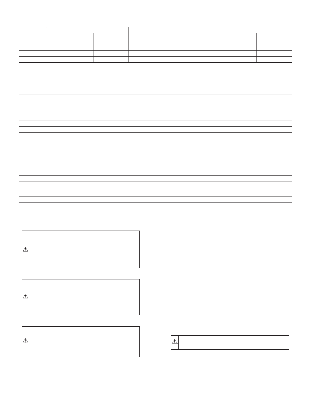
TABLE 1—REFRIGERANT CONNECTIONS AND RECOMMENDED LIQUID AND VAPOR TUBE DIAMETERS (IN.)
UNIT SIZE
018, 024 3/8 3/8 5/8 5/8 5/8 3/4
030, 036 3/8 3/8 3/4 3/4 3/4 7/8
042, 048 3/8 3/8 7/8 7/8 7/8 1-1/8
060 3/8 3/8 7/8 1-1/8 7/8 1-1/8
NOTES:
1. Tube diameters are for lengths up to 50 ft. For tubing lengths greater than 50 ft, consult the Application Guideline and Service Manual—Air Conditioners and Heat Pumps
Using Puron®.
2. Do not apply capillary tube indoor coils to these units.
Connection Diameter Tube Diameter Connection Diameter Tube Diameter Connection Diameter Tube Diameter
LIQUID VAPOR VAPOR (LONG LINE)
TABLE 2—ACCESSORY USAGE
REQUIRED FOR
ACCESSORY
Crankcase Heater Yes Yes No
Evaporator Freeze Thermostat Yes No No
Winter Start Control Yes† No No
Accumulator No No No
Compressor Start Assist
Capacitor and Relay
MotorMaster® Control,
Low-Ambient Pressure Switch
Liquid-Line Solenoid Valve
Ball Bearing Fan Motor Yes‡ No No
* For Tubing Sets between 50 and 175 ft horizontal or 20 ft vertical differential, refer to the Application Guideline and Service Manual—Air Conditioners and Heat Pumps
Using Puron®.
† Only when low-pressure switch is used.
‡ Required for low-ambient controller (full modulation feature) and MotorMaster® Control only.
or
Wind Baffle See Low-Ambient Instructions No No
Coastal Filter No No Yes
Support Feet Recommended No Recommended
or
Hard Shutoff TXV
LOW-AMBIENT
APPLICATIONS
(BELOW 55°F)
Yes Yes No
Yes No No
No See Long-Line Application Guideline No
REQUIRED FOR
LONG-LINE
APPLICATIONS*
(OVER 50 FT)
REQUIRED FOR
SEA COAST
APPLICATIONS
(WITHIN 2 MILES)
CAUTION: To prevent improper performance and/or
unit component failures, do not leave system open to
atmosphere any longer than minimum required for installation. POE oil in compressor is extremely susceptible to
moisture absorption. Always keep ends of tubing sealed
during installation.
CAUTION: To prevent improper performance or equipment failure this caution must be followed. If ANY
refrigerant tubing is buried, provide a 6 in. vertical rise at
service valve. Refrigerant tubing lengths up to 36 in. may
be buried without further special consideration. Do not
bury lines over 36 in. in length.
CAUTION: To prevent damage to unit or service valves
observe the following:
• Use a brazing shield.
• Wrap service valves with wet cloth or use a heat sink
material.
Outdoor units may be connected to indoor section using accessory
tubing package or field-supplied refrigerant grade tubing of correct
size and condition. For tubing requirements beyond 50 ft, substantial capacity and performance losses can occur. Following the
recommendations in the Application Guideline and Service
Manual—Air Conditioners and Heat Pumps Using Puron® Refrigerant will reduce these losses. Refer to Table 1 for field tubing
diameters. Refer to Table 2 for accessory requirements.
There are no buried-line applications greater than 36 in.
If refrigerant tubes or indoor coil are exposed to atmosphere, they
must be evacuated to 500 microns to eliminate contamination and
moisture in the system.
A. OUTDOOR UNIT CONNECTED TO FACTORYAPPROVED INDOOR UNIT
Factory refrigerant charge is for a 15 ft line set. Outdoor unit
contains correct system refrigerant charge for operation with ARI
rated indoor unit. Check refrigerant charge for maximum efficiency. The charge must be adjusted based on the actual line set
length. Add or subtract 0.6 oz/ft for line sets longer or shorter than
15 ft.
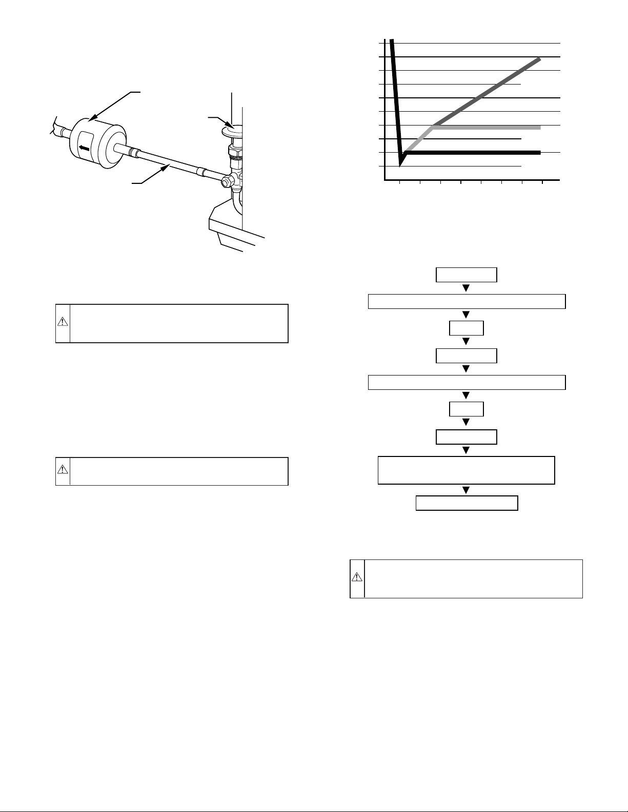
B. INSTALL LIQUID-LINE FILTER DRIER
CAUTION: To avoid performance loss and compressor
failure, installation of filter drier in liquid line is required.
Refer to Fig. 6 and install filter drier as follows:
1. Braze 5-in. connector tube to liquid service valve. Wrap
filter drier with damp cloth.
2. Braze filter drier between connector tube and liquid tube to
indoor coil. Flow arrow must point towards indoor coil.
—4—
Page 5
C. REFRIGERANT TUBING
Connect vapor tube to fitting on outdoor unit vapor service valves.
Connect liquid tube to filter drier. (See Fig. 6 and Table 1.) Use
refrigerant grade tubing.
LIQUID-LINE
FILTER-DRIER
LIQUID
SERVICE
VALVE
CONNECTOR
TUBE
R
-
4
1
0
A
A95509
Fig. 6—Liquid-Line Filter Drier
D. SWEAT CONNECTION
CAUTION: To avoid valve damage while brazing, ser-
vice valves must be wrapped in a heat-sinking material
such as a wet cloth.
5000
4500
4000
3500
LEAK IN
SYSTEM
3000
2500
2000
MICRONS
1500
1000
500
01234567
MINUTES
VACUUM TIGHT
TOO WET
TIGHT
DRY SYSTEM
A95424
A95424
Fig. 7—Deep Vacuum Graph
5. Repeat this procedure as indicated in Fig. 8. System will
then be free of any contaminants and water vapor.
EVACUATE
BREAK VACUUM WITH DRY NITROGEN
WAIT
Use refrigerant grade tubing. Service valves are closed from
factory and ready for brazing. After wrapping service valve with a
wet cloth, braze sweat connections using industry accepted methods and materials. Consult local code requirements. Refrigerant
tubing and indoor coil are now ready for leak testing. This check
should include all field and factory joints.
E. EVACUATE REFRIGERANT TUBING AND INDOOR
COIL
CAUTION: To avoid compressor damage, never use
the system compressor as a vacuum pump.
Refrigerant tubes and indoor coil should be evacuated using the
recommended deep vacuum method of 500 microns. The alternate
triple evacuation method may be used if the procedure outlined
below is followed. Always break a vacuum with dry nitrogen.
DEEP VACUUM METHOD
The deep vacuum method requires a vacuum pump capable of
pulling a vacuum of 500 microns and a vacuum gage capable of
accurately measuring this vacuum depth. The deep vacuum
method is the most positive way of assuring a system is free of air
and liquid water. (See Fig. 7.)
TRIPLE EVACUATION METHOD
The triple evacuation method should only be used when vacuum
pump is only capable of pumping down to 28 in. of mercury
vacuum and system does not contain any liquid water. Refer to
Fig. 8 and proceed is as follows:
1. Pump system down to 28 in. of mercury and allow pump to
continue operating for an additional 15 minutes.
2. Close service valves and shut off vacuum pump.
3. Connect a dry nitrogen cylinder and regulator to system and
open until system pressure is 2 psig.
4. Close service valve and allow system to stand for 1 hr.
During this time, dry nitrogen will be able to diffuse
throughout the system absorbing moisture.
EVACUATE
BREAK VACUUM WITH DRY NITROGEN
WAIT
EVACUATE
CHECK FOR TIGHT, DRY SYSTEM
(IF IT HOLDS DEEP VACUUM)
CHARGE SYSTEM
A95425
Fig. 8—Triple Evacuation Method
VIII. MAKE ELECTRICAL CONNECTIONS
WARNING: To avoid personal injury or death, do not
supply power to unit with compressor terminal box cover
removed.
Be sure field wiring complies with local and national fire, safety,
and electrical codes, and voltage to system is within limits shown
on unit rating plate. Contact local power company for correction of
improper voltage. See unit rating plate for recommended circuit
protection device.
NOTE: Operation of unit on improper line voltage constitutes
abuse and could affect unit reliability. See unit rating plate. Do not
install unit in system where voltage may fluctuate above or below
permissible limits.
NOTE: Use copper wire only between disconnect switch and
unit.
NOTE: Install branch circuit disconnect of adequate size per
NEC to handle unit starting current. Locate disconnect within sight
from and readily accessible from unit, per Section 440-14 of NEC.
—5—
Page 6
A. ROUTE GROUND AND POWER WIRES
Remove access panel to gain access to unit wiring. Extend wires
from disconnect through power wiring hole provided and into unit
control box.
WARNING: The unit cabinet must have an uninterrupted or unbroken ground to minimize personal injury if
an electrical fault should occur. The ground may consist
of electrical wire or metal conduit when installed in
accordance with existing electrical codes. Failure to
follow this warning can result in an electric shock, fire, or
death.
B. CONNECT GROUND AND POWER WIRES
Connect ground wire to ground connection in control box for
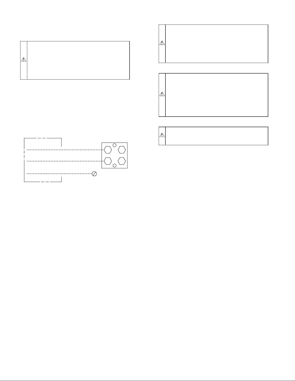
safety. Connect power wiring to contactor as shown in Fig. 9.
DISCONNECT
PER N. E. C. AND/OR
LOCAL CODES
CONTACTOR
FIELD POWER
WIRING
FIELD GROUND
WIRING
GROUND
LUG
A91056
Fig. 9—Line Power Connections
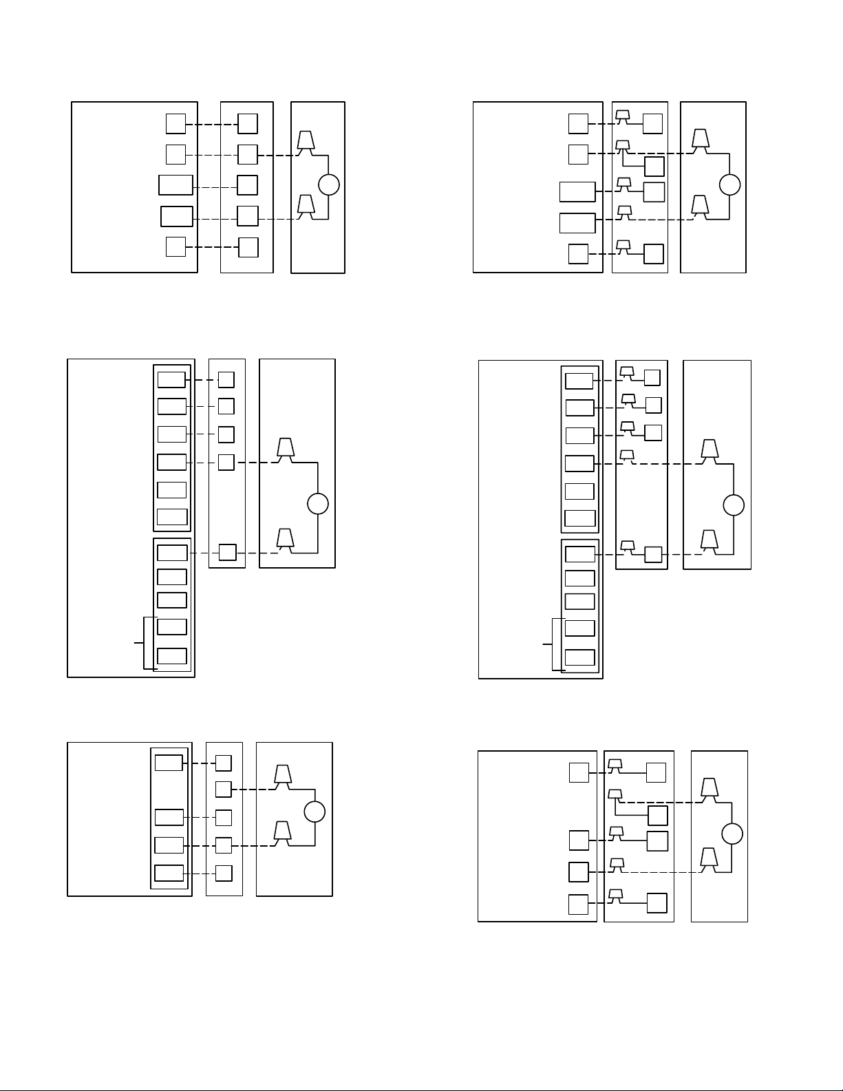
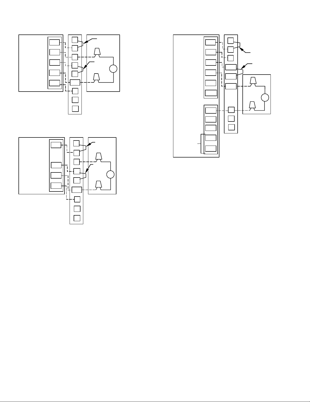
C. CONNECT CONTROL WIRING
Route 24v control wires through control wiring grommet and
connect leads to control wiring. (See Fig. 10.)
Use No. 18 AWG color-coded, insulated (35°C minimum) wire. If
thermostat is located more than 100 ft from unit, as measured
along the control voltage wires, use No. 16 AWG color-coded wire
to avoid excessive voltage drop.
All wiring must be NEC Class 1 and must be separated from
incoming power leads.
Use furnace transformer, fan coil transformer, or accessory transformer for control power, 24v/40va minimum.
NOTE: Use of available 24v accessories may exceed the minimum 40-va power requirement. Determine total transformer loading and increase the transformer capacity or split the load with an
accessory transformer as required.
IX. COMPRESSOR CRANKCASE HEATER
When equipped with a crankcase heater, furnish power to heater a
minimum of 24 hr before starting unit. To furnish power to heater
only, set thermostat to OFF and close electrical disconnect to
outdoor unit.
A crankcase heater is required if refrigerant tubing is longer than
50 ft. Refer to the Application Guideline and Service Manual—Air
Conditioner and Heat Pump Using Puron® Refrigerant.
X. INSTALL ELECTRICAL ACCESSORIES
Refer to the individual instructions packaged with kits or accessories when installing.
XI. START-UP
CAUTION: To prevent compressor damage or personal
injury, observe the following:
• Do not overcharge system with refrigerant.
• Do not operate unit in a vacuum or at negative pressure.
• Do not disable low-pressure switch.
In scroll compressor applications:
• Dome temperatures may be hot.
CAUTION: To prevent personal injury wear safety
glasses, protective clothing, and gloves when handling
refrigerant and observe the following:
• Back seating service valves are not equipped with
Schrader valves. Fully back seat (counter clockwise)
valve stem before removing gage port cap.
• Front seating service valves are equipped with Schrader
valves.
CAUTION: Federal regulations require that you do not
vent refrigerant to atmosphere. Recover during system
repair or final unit disposal.
Follow these steps to properly start up the system:
1. After system is evacuated, fully back seat (open) liquid and
vapor service valves.
2. Unit is shipped with valve stem(s) front seated (closed) and
caps installed. Replace stem caps after system is opened to
refrigerant flow (back seated). Replace caps finger-tight and
tighten with wrench an additional 1/12 turn.
3. Close electrical disconnects to energize system.
4. Set room thermostat at desired temperature. Be sure set
point is below indoor ambient temperature.
5. Set room thermostat to COOL and fan control to ON or
AUTO mode, as desired. Operate unit for 15 minutes.
Check system refrigerant charge.
A. SEQUENCE OF OPERATION
Turn on power to indoor and outdoor units. Transformer is
energized.
On a call for cooling, thermostat makes circuits R-Y and R-G.
Circuit R-Y energizes contactor, starting outdoor fan motor and
compressor circuit. R-G energizes indoor unit blower relay,
starting indoor blower motor on high speed.
When thermostat is satisfied, its contacts open, de-energizing
contactor and blower relay. Compressor and motors stop.
If indoor unit is equipped with a time-delay relay circuit, the
indoor blower will run an additional 90 sec to increase system
efficiency.
XII. CHECK CHARGE
A. UNIT CHARGE
Factory charge and charging method are shown on unit information plate. Puron® refrigerant cylinders contain a dip tube
which allows liquid refrigerant to flow from cylinder in
upright position. Charge Puron® units with cylinder in upright
position and a commercial-type metering device in manifold hose.
Charge refrigerant into suction line.
NOTE: Charge must be adjusted in accordance with unit rating
plate, ±0.6 oz/ft of 3/8-in. liquid line above or below 15 ft,
respectively.
—6—
Page 7
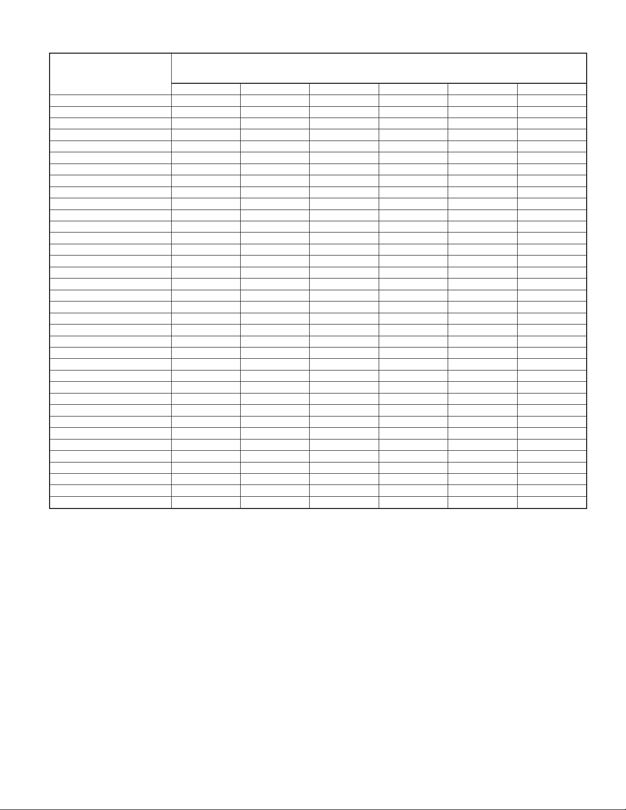
TABLE 3—REQUIRED LIQUID-LINE TEMPERATURE (°F)
LIQUID
PRESSURE AT
SERVICE VALVE
(PSIG)
189 58 56 54 52 50 48
195 60 58 56 54 52 50
202 62 60 58 56 54 52
208 64 62 60 58 56 54
215 66 64 62 60 58 56
222 68 66 64 62 60 58
229 70 68 66 64 62 60
236 72 70 68 66 64 62
243 74 72 70 68 66 64
251 76 74 72 70 68 66
259 78 76 74 72 70 68
266 80 78 76 74 72 70
274 82 80 78 76 74 72
283 84 82 80 78 76 74
291 86 84 82 80 78 76
299 88 86 84 82 80 78
308 90 88 86 84 82 80
317 92 90 88 86 84 82
326 94 92 90 88 86 84
335 96 94 92 90 88 86
345 98 96 94 92 90 88
354 100 98 96 94 92 90
364 102 100 98 96 94 92
374 104 102 100 98 96 94
384 106 104 102 100 98 96
395 108 106 104 102 100 98
406 110 108 106 104 102 100
416 112 110 108 106 104 102
427 114 112 110 108 106 104
439 116 114 112 110 108 106
450 118 116 114 112 110 108
462 120 118 116 114 112 110
474 122 120 118 116 114 112
486 124 122 120 118 116 114
499 126 124 122 120 118 116
511 128 126 124 122 120 118
8 1012141618
REQUIRED SUBCOOLING
TEMPERATURE
(°F)
EXAMPLE:
To calculate additional charge requried for a 25-ft line set:
25 ft - 15 ft = 10 ft X 0.6 oz/ft=6ozofadditional charge.
B. COOLING ONLY PROCEDURE
UNITS WITH COOLING MODE PURON® TXV
Units installed with cooling mode TXV require charging by the
subcooling method.
1. Operate unit a minimum of 10 minutes before checking
charge.
2. Measure liquid service valve pressure by attaching an
accurate gage to service port.
3. Measure liquid line temperature by attaching an accurate
thermistor type or electronic thermometer to liquid line near
outdoor coil.
4. Refer to unit rating plate for required subcooling temperature.
5. Refer to Table 3. Find the point where required subcooling
temperature intersects measured liquid service valve pressure.
6. To obtain required subcooling temperature at a specific
liquid line pressure, add refrigerant if liquid line temperature is higher than indicated or reclaim refrigerant if
temperature is lower. Allow a tolerance of ± 3°F.
UNITS WITH INDOOR PISTONS
Units installed with indoor pistons require charging by the superheat method.
The following procedure is valid when indoor airflow is within ±
21 percent of its rated CFM.
1. Operate unit a minimum of 10 minutes before checking
charge.
2. Measure suction pressure by attaching an accurate gage to
suction valve service port.
3. Measure suction temperature by attaching an accurate
thermistor type or electronic thermometer to suction line at
service valve.
4. Measure outdoor air dry-bulb temperature with thermometer.
5. Measure indoor air (entering indoor coil) wet-bulb temperature with a sling psychrometer.
—7—
Page 8
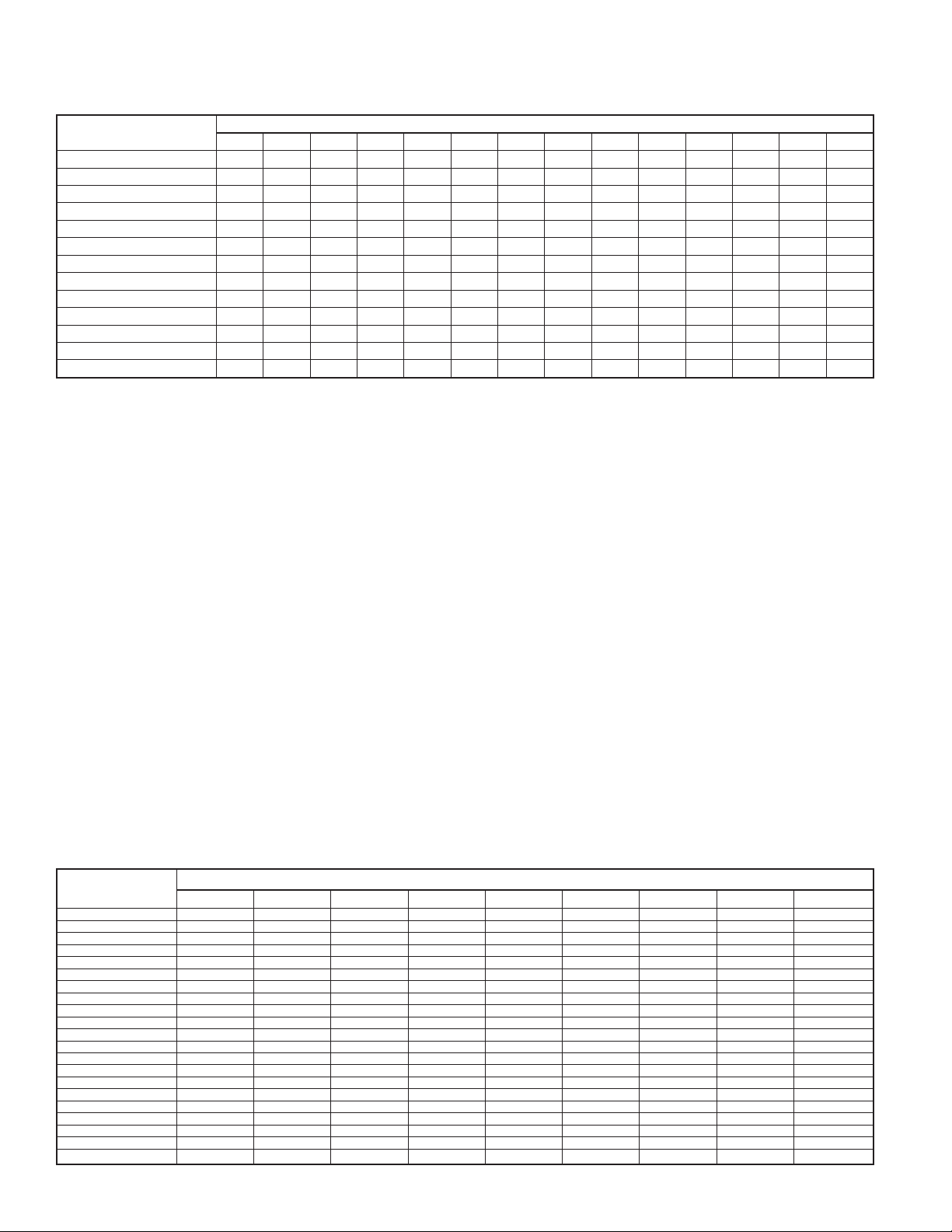
TABLE 4—SUPERHEAT CHARGING
OUTDOOR TEMP (°F)
55 9 12141720232629323537404245
60 7 10121518212427303335384043
65 — 6 10 13 16 19 21 24 27 30 33 36 38 41
70 —— 7 1013161921242730333639
75 — — — 6 9 12 15 18 21 24 28 31 34 37
80 ————5 81215182125283135
85 ——————811151922263033
90 ——————5 9131620242731
95 ———————6101418222529
100 ———————— 81215202327
105 ———————— 5 913172226
110 ————————— 611152025
115 —————————— 8141823
Where a dash (—) appears, do not attempt to charge system under these conditions or refrigerant slugging may occur. Charge must be weighed in.
NOTE: Superheat °F is at low-side service port.
50 52 54 56 58 60 62 64 66 68 70 72 74 76
EVAPORATOR ENTERING AIR TEMPERATURE (°F WB)
6. Refer to Table 4. Find outdoor temperature and evaporator
entering air wet-bulb temperature. At this intersection, note
superheat.
7. Refer to Table 5. Find superheat temperature located in item
6 and suction pressure. At this intersection, note suction line
temperature.
8. If unit has a higher suction line temperature than charted
temperature, add refrigerant until charted temperature is
reached.
9. If unit has a lower suction line temperature than charted
temperature, reclaim refrigerant until charted temperature is
reached.
10. When adding refrigerant, charge in liquid form into suction
service port using a flow-restricting device.
11. If outdoor air temperature or pressure at suction valve
changes, charge to new suction line temperature indicated
on chart.
XIII. FINAL CHECKS
IMPORTANT: Before leaving job, be sure to do the following:
1. Ensure that all wiring is routed away from tubing and sheet
metal edges to prevent rub-through or wire pinching.
TABLE 5—REQUIRED SUCTION-LINE TEMPERATURE
SUPERHEAT
TEMP
(°F)
0 35 37 39 41 43 45 47 49 51
2 37 39 41 43 45 47 49 51 53
4 39 41 43 45 47 49 51 53 55
6 41 43 45 47 49 51 53 55 57
8 43 45 47 49 51 53 55 57 59
10 45 47 49 51 53 55 57 59 61
12 47 49 51 53 55 57 59 61 63
14 49 51 53 55 57 59 61 63 65
16 51 53 55 57 59 61 63 65 67
18 53 55 57 59 61 63 65 67 69
20 55 57 59 61 63 65 67 69 71
22 57 59 61 63 65 67 69 71 73
24 59 61 63 65 67 69 71 73 75
26 61 63 65 67 69 71 73 75 77
28 63 65 67 69 71 73 75 77 79
30 65 67 69 71 73 75 77 79 81
32 67 69 71 73 75 77 79 81 83
34 69 71 73 75 77 79 81 83 85
36 71 73 75 77 79 81 83 85 87
38 73 75 77 79 81 83 85 87 89
40 75 77 79 81 83 85 87 89 91
107.8 112.2 116.8 121.2 126.0 130.8 138.8 140.8 145.8
SUCTION PRESSURE AT SERVICE PORT (PSIG)
2. Ensure that all wiring and tubing is secure in unit before
adding panels and covers. Securely fasten all panels and
covers.
3. Tighten service valve stem caps to 1/12-turn past finger
tight.
4. Leave User’s Manual with owner. Explain system operation
and periodic maintenance requirements outlined in manual.
5. Fill out Dealer Installation Checklist and place in customer
file.
CARE AND MAINTENANCE
For continuing high performance and to minimize possible equipment failure, periodic maintenance must be performed on this
equipment.
Frequency of maintenance may vary depending upon geographic
areas, such as coastal applications. See Users Manual for information.
—8—
Page 9
BRYANT
NON-PROGRAMMABLE
THERMOSTAT
MODEL AC
SINGLE-STAGE
FURNACE
AIR
CONDITIONER
BRYANT
NON-PROGRAMMABLE
THERMOSTAT
MODEL AC
FA, FB, FC,
FD, FF
FAN COIL
AIR
CONDITIONER
24 VAC HOT
24 VAC COM
HEAT STAGE 1
COOL STAGE 1
INDOOR FAN
BRYANT
PROGRAMMABLE
THERMOSTAT
MODEL AC
24 VAC HOT
INDOOR FAN
HEAT STAGE 1
COOL STAGE 1
NOT USED
NOT USED
R
C
W/W1
Y/Y2
G
R
G
W/W1
Y/Y2
O/W2
Y1/W 2
R
C
W
Y
G
SINGLE-STAGE
FURNACE
R
G
W
Y
AIR
CONDITIONER
C
C
SEE
NOTE 2
SEE
NOTE 2
A97359
24 VAC HOT
24 VAC COM
HEAT STAGE 1
COOL STAGE 1
INDOOR FAN
BRYANT
PROGRAMMABLE
THERMOSTAT
MODEL AC
24 VAC HOT
INDOOR FAN
HEAT STAGE 1
COOL STAGE 1
NOT USED
NOT USED
R
C
W/W1
Y/Y2
G
R
G
W/W1
Y/Y2
O/W2
Y1/W2
R
C
W2
G
FA, FB,
FC, FD, FF
FAN COIL
R
G
W2
C
AIR
CONDITIONER
C
SEE
NOTE 2
A97360
SEE
NOTE 2
24 VAC COM
NOT USED
NOT USED
OPTIONAL
OUTDOOR
SENSOR
CONNECTION
OTHER
NON-PROGRAMMABLE
AC THERMOSTAT
24 VAC HOT
HEAT STAGE 1
COOL STAGE 1
INDOOR FAN
C
B
L
S1
S2
R
W
Y
G
C
SINGLE-STAGE
FURNACE
R
C
W
Y
G
AIR
CONDITIONER
C
Fig. 10—Typical 24v Circuit Connections
SEE
NOTE 2
A97361
A97367
24 VAC COM
NOT USED
NOT USED
OPTIONAL
OUTDOOR
SENSOR
CONNECTION
C
B
L
S1
S2
OTHER
NON-PROGRAMMABLE
AC THERMOSTAT
24 VAC HOT
HEAT STAGE 1
COOL STAGE 1
INDOOR FAN
R
W
Y
G
C
FA, FB, FC,
FD, FF
FAN COIL
R
C
W2
G
AIR
CONDITIONER
C
A97362
SEE
NOTE 2
A97366
—9—
Page 10
BRYANT
NON-PROGRAMMABLE
THERMOSTAT
MODEL AC
24 VAC HOT
24 VAC COM
HEAT STAGE 1
COOL STAGE 1
INDOOR FAN
R
C
W/W1
Y/Y2
G
FK4C
FAN COIL
DH
R
C
W1
W2
Y/Y2
G
O
AIR
CONDITIONER
J1 JUMPER
J2 JUMPER
BRYANT
PROGRAMMABLE
THERMOSTAT
MODEL AC
24 VAC HOT
INDOOR FAN
SEE
C
NOTE 2
HEAT STAGE 1
COOL STAGE 1
NOT USED
NOT USED
R
G
W/W1
Y/Y2
O/W2
Y1/W2
FK4C
FAN COIL
DH
R
G
W1
W2
Y/Y2
AIR
CONDITIONER
J1 JUMPER
J2 JUMPER
C
SEE
NOTE 2
OTHER
NON-PROGRAMMABLE
AC THERMOSTAT
24 VAC HOT
HEAT STAGE 1
COOL STAGE 1
INDOOR FAN
R
W
Y
G
Y1
FK4C
FAN COIL
DH
R
C
W1
W2
Y/Y2
G
O
Y1
AIR
CONDITIONER
J1 JUMPER
J2
JUMPER
C
SEE
NOTE 2
A97363
A97365
24 VAC COM
NOT USED
NOT USED
OPTIONAL
OUTDOOR
SENSOR
CONNECTION
S1
S2
C
B
L
C
Y1
O
A97364
Fig. 10—Typical 24v Circuit Connections (Continued)
NOTES:
1. BRYANT THERMOSTAT WIRING DIAGRAMS ARE ONLY ACCURATE FOR MODEL NUMBERS TSTAT_______.
2. WIRING MUST CONFORM TO NEC OR LOCAL CODES.
3. SOME UNITS ARE EQUIPPED WITH PRESSURE SWITCH(ES), TEMPERATURE SWITCH, OR 5-MINUTE COMPRESSOR
CYCLE PROTECTION. CONNECT 24V FIELD WIRING TO FACTORY-PROVIDED STRIPPED LEADS.
4. A LIQUID-LINE SOLENOID VALVE IS REQUIRED ON SOME UNITS. SEE SPECIFIC UNIT INSTRUCTIONS.
5. THERMOSTATS ARE FACTORY CONFIGURED WITH 5-MINUTE COMPRESSOR CYCLE PROTECTION AND 4 CYCLES PER
HOUR LIMIT. SEE THERMOSTAT INSTALLATION INSTRUCTIONS FOR DETAILS.
6. TO STAGE ELECTRIC RESISTANCE HEAT, CONSULT OUTDOOR THERMOSTAT INSTALLATION INSTRUCTIONS.
—10—
Page 11

PURON® (R–410A) QUICK REFERENCE GUIDE
• Puron® refrigerant operates at 50-70 percent higher pressures than R-22. Be sure that servicing equipment and replacement
components are designed to operate with Puron®
• Puron® refrigerant cylinders are rose colored.
• Recovery cylinder service pressure rating must be 400 psig, DOT 4BA400 or DOT BW400.
• Puron® systems should be charged with liquid refrigerant. Use a commercial type metering device in the manifold hose when
charging into suction line with compressor operating
• Manifold sets should be 700 psig high side and 180 psig low side with 550 psig low-side retard. • Use hoses with 700 psig
service pressure rating.
• Leak detectors should be designed to detect HFC refrigerant.
• Puron®, as with other HFCs, is only compatible with POE oils.
• Vacuum pumps will not remove moisture from oil.
• Do not use liquid-line filter driers with rated working pressures less than 600 psig.
• Do not leave Puron® suction line filter driers in line longer than 72 hours.
• Do not install a suction-line filter drier in liquid line.
• POE oils absorb moisture rapidly. Do not expose oil to atmosphere.
• POE Oils may cause damage to certain plastics and roofing materials.
• Wrap all filter driers and service valves with wet cloth when brazing.
• A factory approved liquid-line filter drier is required on every unit.
• Do NOT use an R-22 TXV.
• If indoor unit is equipped with an R-22 TXV, it must be changed to a Puron® TXV.
• Never open system to atmosphere while it is under a vacuum.
• When system must be opened for service, recover refrigerant, evacuate then break vacuum with dry nitrogen and replace filter
driers. Evacuate to 500 microns prior to recharging.
• Do not vent Puron® into the atmosphere.
• Do not use capillary tube coils.
• Observe all warnings, cautions, and bold text.
—11—
Page 12

© 2003 Bryant Heating & Cooling Systems 7310 W. Morris St. Indianapolis, IN 46231
—12—
Printed in U.S.A. 550a184 Catalog No. 5355-020
 Loading...