

Page 1
installation, start-up and
566D/E
service instructions
COMMERCIAL AIR-COOLED
CONDENSING UNITS
CONTENTS
Page
SAFETY CONSIDERATIONS . . . . . . . . . . . . . . . . . . . . . . . . . 1
INSTALLATION . . . . . . . . . . . . . . . . . . . . . . . . . . . . . . . . . .1-14
I. Complete Pre-Installation Checks . . . . . . . . . . . . . . 1
II. Rig and Mount the Unit . . . . . . . . . . . . . . . . . . . . . . . 9
III. Complete Refrigerant Piping
Connections . . . . . . . . . . . . . . . . . . . . . . . . . . . . . . 9
IV. Install Accessories . . . . . . . . . . . . . . . . . . . . . . . . . 11
V. Complete Electrical Connections. . . . . . . . . . . . . . 11
PRE-START-UP. . . . . . . . . . . . . . . . . . . . . . . . . . . . . . . . . . . 15
I. System Check . . . . . . . . . . . . . . . . . . . . . . . . . . . . . 15
II. Leak Test and Dehydration . . . . . . . . . . . . . . . . . . . 15
III. Turn On Crankcase Heater . . . . . . . . . . . . . . . . . . . 15
IV. Preliminary Charge . . . . . . . . . . . . . . . . . . . . . . . . . 15
START-UP . . . . . . . . . . . . . . . . . . . . . . . . . . . . . . . . . . . . .15-20
I. 569D, 566E, 569F Units . . . . . . . . . . . . . . . . . . . . . . 15
II. 576C, 566D Units . . . . . . . . . . . . . . . . . . . . . . . . . . . 19
OPERATING SEQUENCE. . . . . . . . . . . . . . . . . . . . . . . . 20, 21
I. Cooling . . . . . . . . . . . . . . . . . . . . . . . . . . . . . . . . . . . 20
II. Heating . . . . . . . . . . . . . . . . . . . . . . . . . . . . . . . . . . . 21
SERVICE . . . . . . . . . . . . . . . . . . . . . . . . . . . . . . . . . . . . . .21-24
I. Capacity Control (576C, 566D Units) . . . . . . . . . . . 21
II. Head Pressure Control
(566D, 566E150-240 Units Only) . . . . . . . . . . . . . 21
III. Time Guard II Circuit (566D Only). . . . . . . . . . . . . . 21
IV. Crankcase Heater . . . . . . . . . . . . . . . . . . . . . . . . . . 22
V. Compressor Protection . . . . . . . . . . . . . . . . . . . . . . 22
VI. Low-Pressure Switches. . . . . . . . . . . . . . . . . . . . . . 22
VII. High-Pressure Switches . . . . . . . . . . . . . . . . . . . . . 22
VIII. Discharge Gas Thermostat . . . . . . . . . . . . . . . . . . . 22
IX. Outdoor Fans . . . . . . . . . . . . . . . . . . . . . . . . . . . . . . 22
X. Lubrication . . . . . . . . . . . . . . . . . . . . . . . . . . . . . . . . 22
XI. Coil Cleaning and Maintenance . . . . . . . . . . . . . . . 22
TROUBLESHOOTING. . . . . . . . . . . . . . . . . . . . . . . . . . . 25, 26
START-UP CHECKLIST . . . . . . . . . . . . . . . . . . . . . CL-1, CL-2
SAFETY CONSIDERATIONS
Installing, starting up, and servicing air-conditioning equipment can be hazardous due to system pressures, electrical
components, and equipment location (roofs, elevated structures, etc.).
Only trained, qualified installers and service mechanics
should install, start-up, and service this equipment.
569D/F
576C
Sizes 072-240
6to20Tons
Cancels: II 569D-72-1 II 569D-72-2
9/15/04
Untrained personnel can perform basic maintenance functions such as cleaning coi ls. All other operat ions should be
performed by trained service personnel.
When working on the equipment, observe precautions in
the literature and on tags, stickers, and labels attached to
the equipment.
Follow all safety codes. Wear safety glasses and work gloves.
Keep quenching cloth and fire extinguisher nearby when
brazing. Use care in handling, rigging, and setting bulky
equipment.
WARNING: Before installing or servicing system,
always turn off main power to system and install lockout tag on disconnect. There may be more than one disconnect switch. Electrical shock can cause personal
injury.
INSTALLATION
I. COMPLETE PRE-INSTALLATION CHECKS
A. Uncrate Unit
Remove unit packaging except for the top skid assembly,
which should be left in place until after the unit is rigged
into its final location.
B. Inspect Shipment
File claim with shipping company if shipment is damaged or
incomplete.
C. Consider System Requirements
• Con sult local b uil ding code s and Nation al Ele ctrica l Code
(NEC) for special installation requirements.
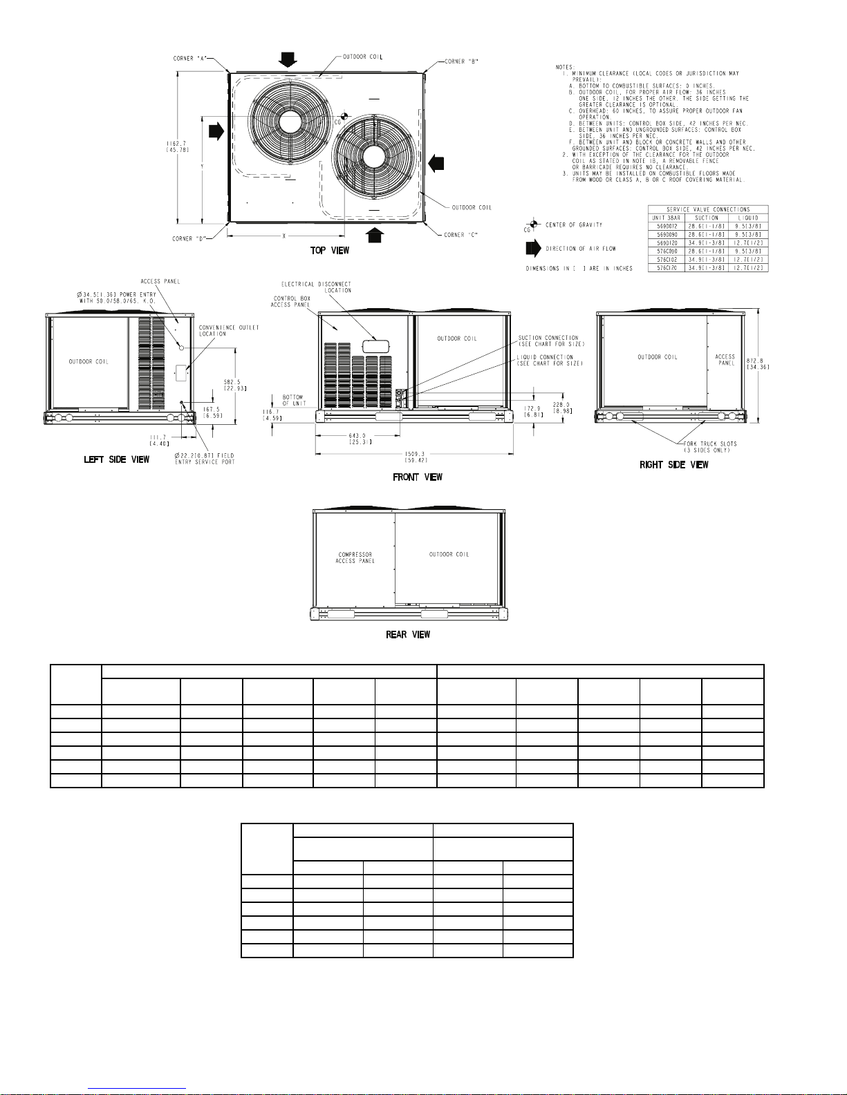
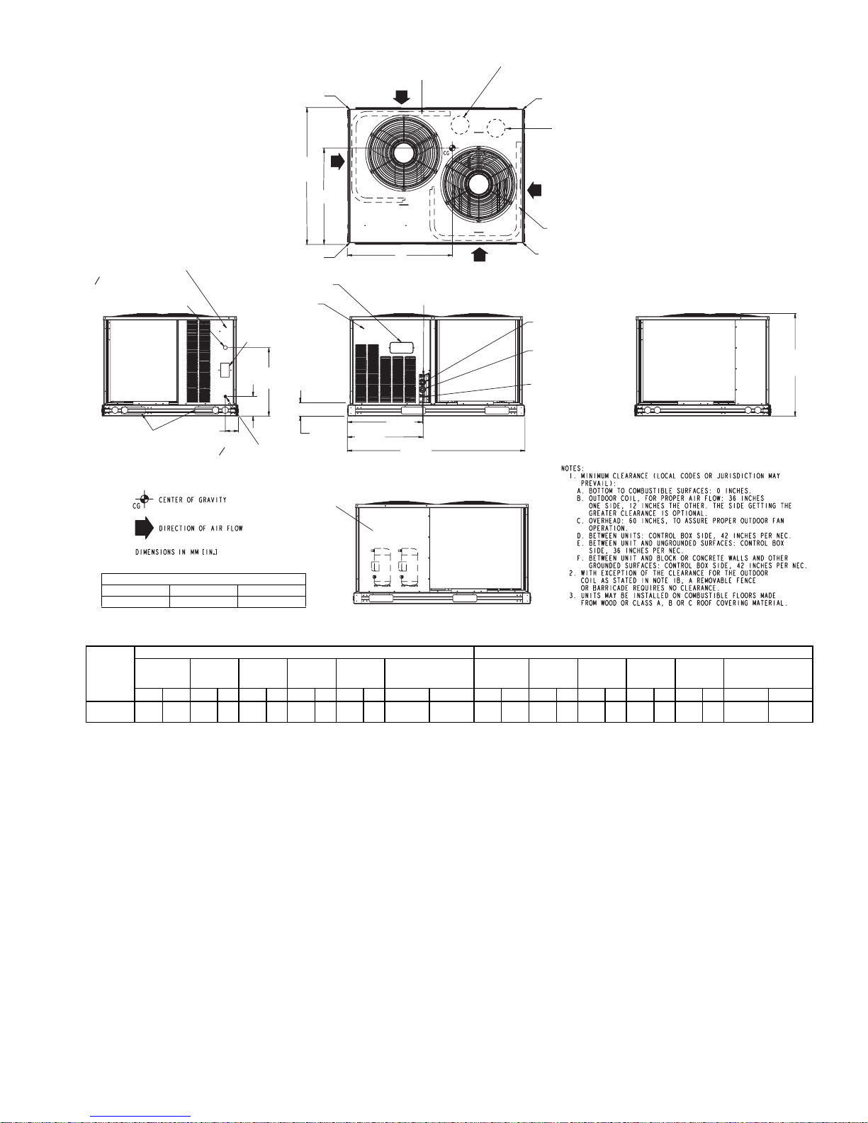
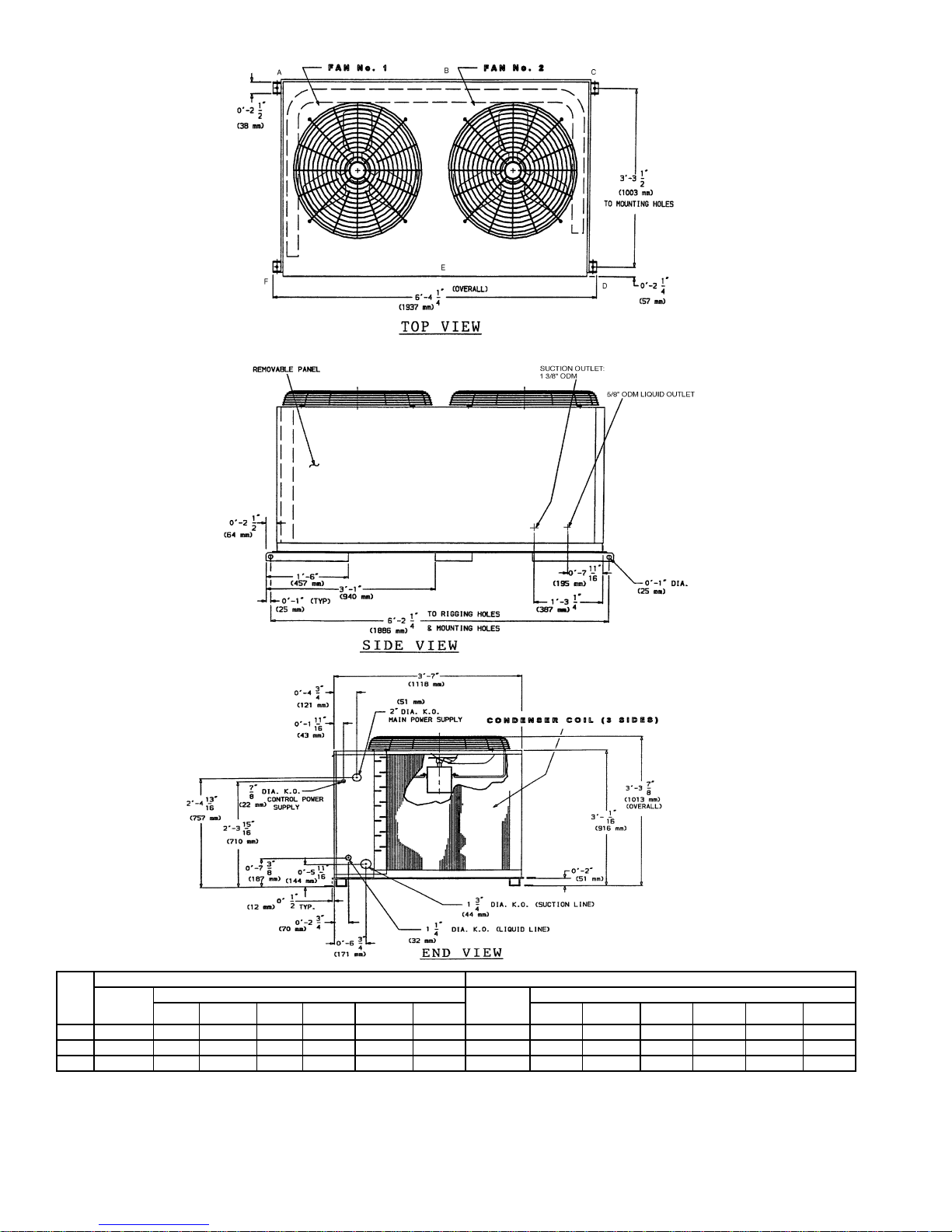
• Allow sufficient space for airflow clearance, wiring, refrigerant piping, and servicing unit. See Fig. 1-4 for unit
dimensions and weight distribution data.
• Locate unit so that outdoor coil (condenser) airflow is
unrestricted on all sides an d ab ove.
• Unit may be mounted on a level pad directly on the base
channels or mounted o n a raised structural stee l frame.
See Tables 1A to 1C for unit operating weights. See
Fig. 1-4 for weight distribution based on recommended
support points.
NOTE: If vibration isolators are required for a particular
installation, use the data in Fig. 1-4 to make the proper
selection.
Page 2
UNIT
569D072 300 (136) 62 (28) 103 (47) 62 (28) 72 (33) 352 (160) 95 (43) 92 (42) 92 (42) 72 (33)
569D090 383 (174) 86 (39) 123 (56) 85 (39) 89 (40) 484 (220) 122 (55) 137 (62) 122 (55) 104 (47)
569D120 430 (195) 84 (38) 166 (75) 66 (30) 114 (52) 531 (241) 121 (55) 176 (81) 103 (47) 128 (58)
576C090 550 (249) 49 (22) 262 (119) 75 (34) 165 (75) 651 (295) 88 (40) 273 (124) 114 (52) 177 (80)
576C102 575 (261) 55 (25) 265 (120) 88 (40) 167 (76) 676 (307) 94 (43) 276 (125) 127 (58) 179 (81)
576C120 575 (261) 55 (25) 265 (120) 88 (40) 167 (76) 676 (307) 94 (43) 276 (125) 127 (58) 179 (81)
Standard
Weight
ALUMINUM COIL lb (kg) COPPER COIL lb (kg)
Corner
A
Corner
B
UNIT
569D072 831.9 [32.75] 641.4 [25.25] 789.7 [31.09] 619.3 [24.38]
569D090 822.3 [32.38] 635.0 [25.00] 806.5 [31.75] 621.8 [24.48]
569D120 812.8 [32.00] 676.3 [26.63] 800.1 [31.50] 656.3 [25.84]
576C090 924.1 [36.38] 657.3 [25.88] 896.4 [35.29] 644.1 [25.36]
576C102 927.1 [36.50] 647.7 [25.50] 900.2 [35.44] 636.3 [25.05]
576C120 927.1 [36.50] 647.7 [25.50] 900.2 [35.44] 636.3 [25.05]
Fig. 1 — 569D072-120, 576C090-120 Unit Dimensions
Corner
C
ALUMINUM COIL COPPER COIL
Center of Gravity
mm [in.]
XYXY
Corner
D
Standard
Weigh t
Center of Gravity
mm [in.]
Corner
A
—2—
Corner
B
Corner
C
Corner
D
Page 3
CORNER A
1162.7
[45.78]
OUTDOOR COIL
COMPRESSOR # 1
CORNER B
COMPRESSOR # 2
Y
OUTDOOR COIL
ACCESS PANEL
O 34.5 [1.36]
POWER ENTRY
WITH 50.0/58.0/65. K.O.
OUTDOOR
COIL
FORK TRUCK SLOTS
(3 SIDES ONLY)
111.7
[4.40]
O 22.2 [0.87] FIELD
ENTRY SERVICE PORT
CORNER D
ELECTRICAL DISCONNECT
LOCATION
CONTROL BOX
ACCESS PANEL
CONVENIENCE
OUTLET LOCATION
582.5
167.5
[6.59]
[22.93]
BOTTOM
OF UNIT
116.7
[4.59]
644.6
[25.38]
LEFT SIDE VIEW
COMPRESSOR
ACCESS PANEL
SERVICE VALVE CONNECTIONS
UNIT SUCTION LIQUID
569F120
569F120 11/8(2)
UNIT
569F120 488 221 102 46 143 65 139 63 104 47
1-1/8
Std.
Unit
Wt.
lb kg lb kg lb kg lb kg lb kg X Y lb kg lb kg lb kg lb kg lb kg X Y
3/8
3
/8(2)
ALUMINUM COIL COPPER COIL
CornerACornerBCornerCCornerDCenter of Gravity
X
TOP VIEW
CIRCUIT #2
LIQUID CONNECTION (3/8")
OUTDOOR
COIL
637.9
[25.11]
1509.3
[59.42]
FRONT VIEW
OUTDOOR
#2
#1
COIL
REAR VIEW
mm [in.]
873.8
[34.4]
591.8
589 267 129 59 166 75 164 74 130 59
[23.3]
CORNER C
CIRCUIT #2
SUCTION
CONNECTION (1 1/8")
CIRCUIT #1
SUCTION
CONNECTION (1 1/8")
CIRCUIT #1
LIQUID CONNECTION
Std.
Unit
Wt.
CornerACornerBCornerCCornerDCenter of Gravity
(3/8")
OUTDOOR
COIL
ACCESS
RIGHT SIDE VIEW
845.8
[33.3]
PANEL
mm [in.]
872.8
[34.36]
579.1
[22.8]
Fig. 2 — 569F120 Unit Dimensions
—3—
Page 4
UNIT
Standard
566D
Weight
lb (kg)
150 779 (354) 70 (32) 177 (80) 68 (31) 100 (45) 261 (119) 103 (47) 919 (418) 99 (45) 224 (102) 96 (44) 114 (52) 268 (122) 118 (54)
180 789 (359) 70 (32) 180 (82) 69 (31) 101 (46) 265 (120) 104 (47) 929 (422) 99 (45) 228 (104) 96 (44) 115 (52) 273 (124) 118 (54)
240 900 (422) 84 (38) 234 (106) 82 (37) 108 (49) 310 (141) 111 (50) 1040 (473) 110 (50) 283 (129) 107 (49) 116 (53) 305 (139) 119 (54)
NOTES:
1. Service clearances are as follows:
Side (compressor) — 3
Side (opposite compressor) — 3 ft (914 mm)
Ends — 2 ft (610 mm)
Top—5ft(1524mm)
ABCD E F A B C D E F
ALUMINUM COIL COPPER COIL
Operational Weight Points lb (kg) Standard
1
/2ft (1067 mm)
Weight
lb (kg)
2. Corner weights are approximate.
3. Actual support weights depend on level of unit and evenness of support
posts.
4. Total weights represent approximate unit weights without shipping package.
5. Bottom or top skid is NOT included in the weights.
Fig. 3 — 566D150-240 Unit Dimensions
—4—
Operational Weight Points lb (kg)
Page 5

A
B
C
F
E
D
#1
#2
UNIT
Standard
566E
Weight
lb (kg)
150 676 (307) 84 (38) 168 (76) 72 (33) 78 (35) 183 (83) 91 (41) 822 (373) 118 (54) 219 (100) 103 (47) 90 (41) 190 (86) 102 (46)
180 740 (336) 86 (39) 186 (85) 71 (32) 82 (37) 216 (98) 99 (45) 886 (403) 119 (54) 238 (129) 102 (46) 95 (43) 221 (100) 111 (50)
240 764 (347) 87 (40) 192 (87) 72 (33) 85 (39) 226 (103) 102 (46) 904 (411) 120 (55) 243 (110) 102 (46) 96 (44) 230 (105) 113 (51)
NOTES:
1. Service clearances are as follows:
Side (compressor) — 3
Side (opposite compressor) — 3 ft (914 mm)
Ends — 2 ft (610 mm)
Top—5ft(1524mm)
2. Corner weights are approximate.
ABCDE F A B CDE F
ALUMINUM COIL COPPER COIL
Operational Weight Points lb (kg) Standard
1
/2ft (1067 mm)
Weigh t
lb (kg)
3. Actual support weights depend on level of unit and evenness of support
posts.
4. Total weights represent approximate unit weights without shipping
package.
5. Bottom or top skid is NOT included in the weights.
Fig. 4 — 566E150-240 Unit Dimensions
—5—
Operational Weight Points lb (kg)
Page 6
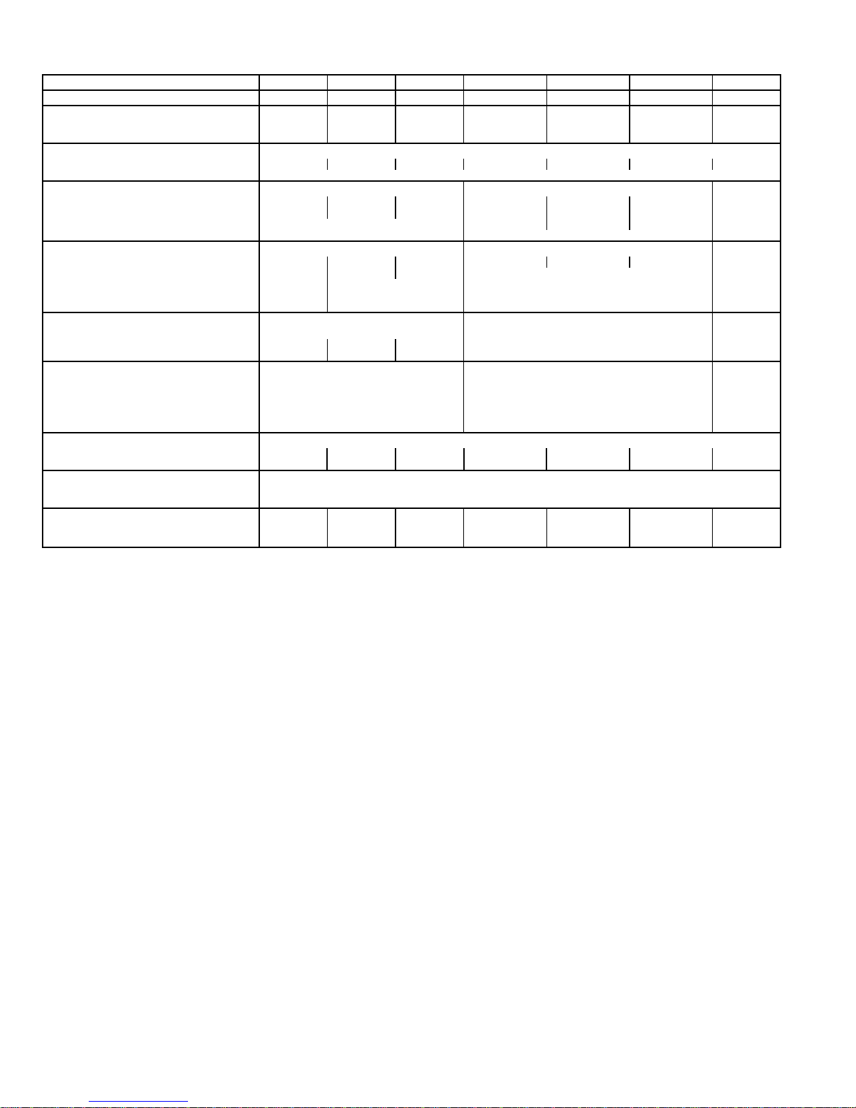
Table 1A — Physical Data — 569D072-120, 576C090-120, 569F120 Units
UNIT SIZE 569D072 569D090 569D120 576C090 576C102 576C120 569F120
1
NOMINAL CAPACITY (tons) 67
OPERATING WEIGHT (lb)
Aluminum-Fin Coils (Standard) 300 383 430 550 575 575 488
/
2
10 71/
2
81/
2
10 10
Copper-Fin Coils (Optional) 352 484 531 651 676 676 589
REFRIGERANT TYPE* R-22
Operating Charge, Typical (lb)† 12 20 22 20 24 24 11/Circuit
Shipping Charge (lb) 2.0
COMPRESSOR Scroll Reciprocating Scroll
Qty...Model 1...SR_68 1...SR_94 1...ZR125 1...06DA818 1...06DA824 1...06DH824 2...SR_60
Oil Charge (oz) 88 90 110 88 128 128 72 (ea)
No. Cylinders N/A 4 6 6 N/A
Speed (rpm) 3500 1750 3500
CONDENSER FANS
Qty...Rpm 2...850 2...1100 2...1100 2...1100 2...1100 2...1100 2...1100
Motor Hp
Diameter 22 22 22 22
Nominal Airflow (Cfm Total) 5400 6500 6500 6500
Watts (Total) 340 570 570 570
1
/
8
1
/
4
1
/
4
1
/
4
1
/
4
CONDENSER COIL (Qty) 222
Face Area (sq ft total) 29.2 29.2 29.2
Rows...Fins/in. 1...17 2...17 2...17 2...17 2...17
Storage Capacity (lb)** 17.3 34.2 34.2 34.2 17.1 (ea)
CONTROLS
Pressurestat Settings (psig)
High Cutout 428 ± 10 428 ± 10 428 ± 10
Cut-in 320 ± 20 320 ± 20 320 ± 20
Low Cutout 27 ± 3 27 ± 3 27 ± 3
Cut-in 44 ± 5 44 ± 5 44 ± 5
DISCHARGE GAS THERMOSTAT (F)
Cutout — 270 ± 9 — — — — —
Cut-in — 190 ± 13 — — — — —
PRESSURE RELIEF
Location Suction Line
Temperature (F) 200
PIPING CONNECTIONS (in. ODM)
Qty...Suction 1...1
Qty...Liquid 1...3/
*Unit is factory-supplied with holding charge only.
†Typical operating charge with 25 ft of interconnecting piping.
**Storage capacity of condenser coil with coil 80% full of liquid R-22 at
95 F.
1
/
1...11/
8
8
1...3/
8
1...13/
8
1...1/
8
2
1...11/
1...3/
8
8
1...13/
1...1/
8
2
1...13/
1...1/
8
2
2...11/
2...3/
8
8
NOTE: Unit 576C120 has one step of unloading. Full load is at 100% of
capacity, and one step of unloading is 67% capacity. Unit 576C120 has
the following unloader settings: load is 70 ± 1 psig and unload is 60 ±
2psig.
—6—
Page 7
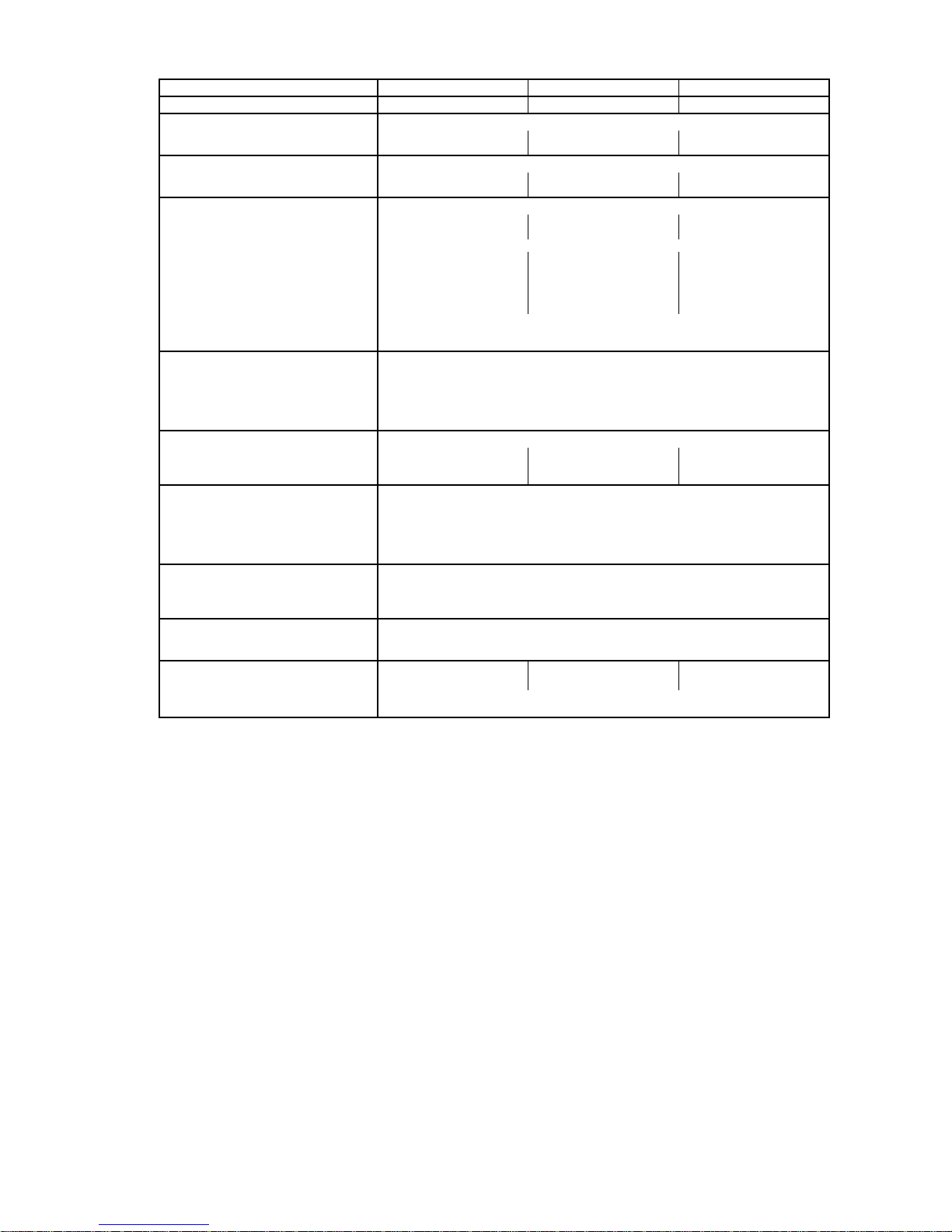
Table 1B — Physical Data — 566D150-240 Units
UNIT SIZE 566D150 566D180 566D240
NOMINAL CAPACITY (tons) 12
OPERATING WEIGHTS (lb)
Aluminum-Fin Coil (Standard) 779 789 900
1
/
2
15 20
Copper-Fin Coil (Optional) 919 929 1040
REFRIGERANT TYPE* R-22
Operating Charge, Typical (lb)† 23 23 28
Shipping Charge (lb) 3.1 3.1 3.1
COMPRESSOR Reciprocating, Semi-Hermetic
Qty...Model 1...06DD328 1...06DD537 1...06E4250
No. Cylinders 664
Speed (rpm) 1750
Oil Charge (pt) 10 10 15.5
Capacity Steps
Accessory 33**, 66, 100 33**, 66, 100 —
Standard 66, 100 66, 100 50, 100
Unloader Setting (psig)
Load 70 ± 1
Unload 60 ± 2
Crankcase Heater Watts 125
CONDENSER FANS Axial Flow, Direct Drive
Qty...Rpm 2...1075
Diameter (in.) 26
Nominal Hp
Nominal Airflow (cfm, total) 11,000
1
/
2
Watts (total) 1460
CONDENSER COIL Copper Tubes, Aluminum Fins
Rows...Fins/in. 3...15 3...15 3...15
Face Area (sq ft) 29.2 29.2 29.2
Storage Capacity (lb)†† 40.3 39.8 39.8
CONTROLS
Pressurestat (psig)
High Cutout 395 ± 10
Cut-in 295 ± 20
Low Cutout 27 ± 4
Cut-in 67 ± 7
FAN CYCLING CONTROLS
Operating Pressure (psig)
No. 2 Fan, Close 255 ± 10
Open 160 ± 10
PRESSURE RELIEF
Location Liquid Line
Temperature (F) 200
PIPING CONNECTIONS (in. ODM)
Suction 1
Liquid
Hot Gas Stub
3
/
8
13/
8
5
/
8
3
/
8
15/
8
*Unit is factory-supplied with holding charge only.
†Typical operating charge with 25 ft of interconnecting piping. Operating charge is approximate for maximum system capacity.
**Indicates capacity step (%) with electric unloader accessory.
††Storage capacity is measured at liquid saturated temperatures of 123 F for 566D150 and 130 F for 566D180 and 240.
—7—
Page 8
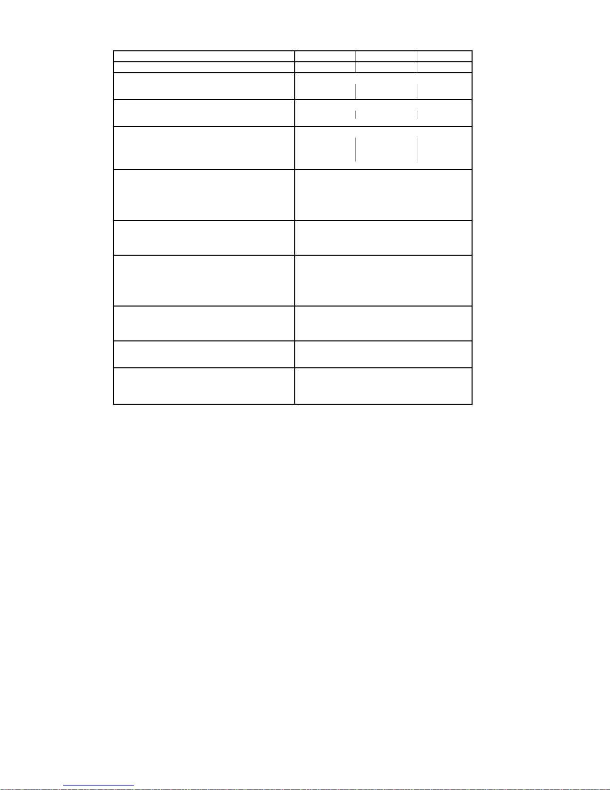
Table 1C — Physical Data — 566E150-240 Units
UNIT SIZE 566E150 566E180 566E240
1
NOMINAL CAPACITY (tons) 12
OPERATING WEIGHTS (lb)
Aluminum-Fin Coil (Standard) 676 740 764
/
2
15 20
Copper-Fin Coil (Optional) 822 886 904
REFRIGERANT TYPE* R-22
Operating Charge, Typical (lb)† 11.5/Circuit 11.5/Circuit 14/Circuit
Shipping Charge (lb) 3.1
COMPRESSOR Scroll
Qty...Model 2...ZR72 2...ZR94 2...ZR125
Speed (rpm) 3500 3500 3500
Oil Charge (oz) 60 (ea) 85 (ea) 110 (ea)
Crankcase Heater Watts 70
CONDENSER FANS
Qty...Rpm 2...1075
Diameter (in.) 26
Nominal Hp
Nominal Airflow (cfm, total) 11,000
Watts (total) 1460
1
/
2
CONDENSER COIL
Rows...Fins/in. 3...15
Face Area (sq ft total) 29.2
Storage Capacity (lb)** 48
CONTROLS
Pressurestat (psig)
High Cutout 426 ± 7
Cut-in 320 ± 20
Low Cutout 27 ± 4
Cut-in 67 ± 7
FAN CYCLING CONTROLS
Operating Pressure (psig)
No. 2 Fan, Close 255 ± 10
Open 160 ± 10
PRESSURE RELIEF
Location Liquid Line
Temperature (F) 200
PIPING CONNECTIONS (in. ODM)
Suction (2) 1
Liquid (2)1/
Hot Gas Stub
*Unit is factory-supplied with holding charge only.
†Typical operating charge with 25 ft of interconnecting piping. Operating charge is approximate for maxi-
3
/
8
2
3
/
8
mum system capacity.
**Storage capacity is measured at liquid saturated temperatures of 123 F for 566E150 and 130 F for
566E180 and 240.
—8—
Page 9
II. RIG AND MOUNT THE UNIT
CAUTION: Be sure unit panels are securely in
place prior to rigging.
A. Rigging
These units are designed for o verhead rigging. Refer to rigging label for preferred rigging method. Spreader bars are
not required if top crating is left on unit. All panels must be
in place when rigging. As further protection for coil faces,
plywood sheets may be placed against sides of unit, behind
cables. Run cables to a central suspension point so that angle
from the horizontal is not less than 45 degrees. Raise and set
unit down carefully.
If it is necessary to r o ll th e uni t int o po si ti on , mo unt the u nit
on longitudinal rails, using a minimum of 3 rollers. Apply
force to the rails, not the unit. If the unit is to be skidded into
position, place it on a large pad and drag it by the pad. Do
not apply any force to the unit.
Raise from above to lift unit from the rails or pad when unit
is in final position.
After unit in position, remove all shipping materials and to p
crating.
B. Compressor Mounting
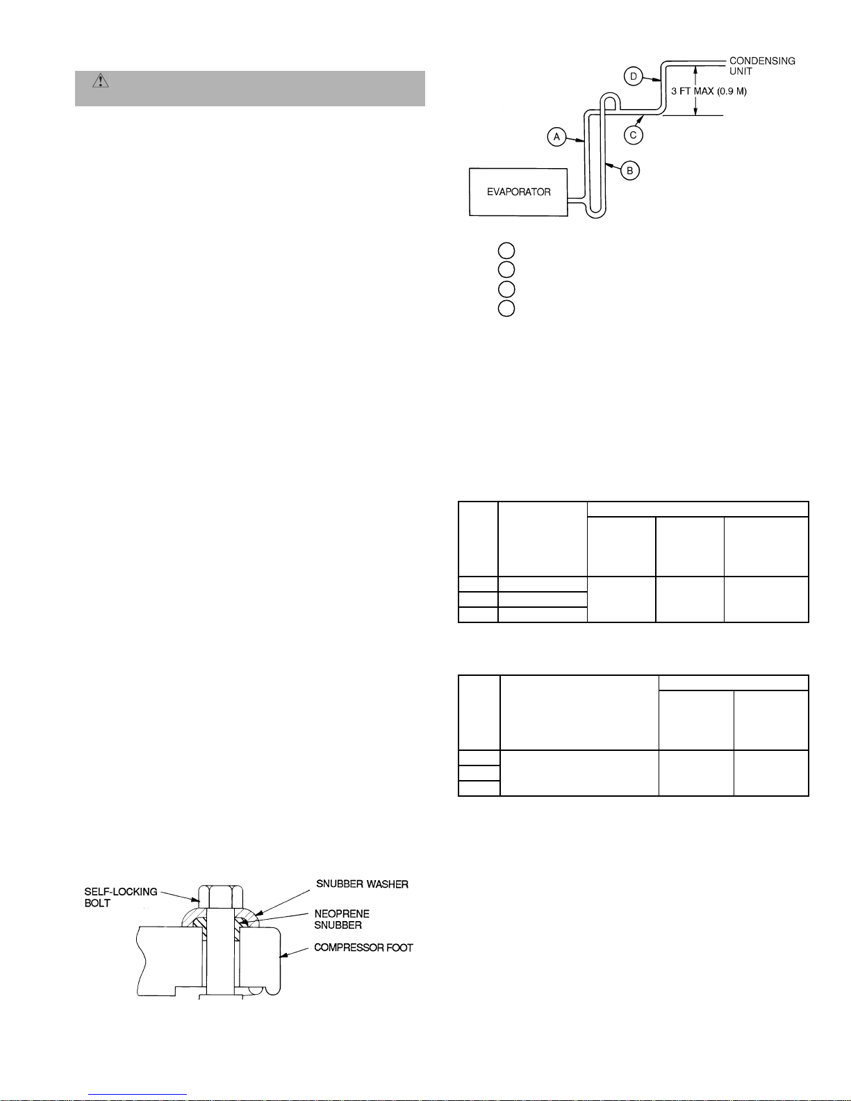
As shipped, the compressor is held tightly in place by selflocking bolts. Before starting unit, loosen self-locking
bolts until the snubber washer can be moved sideways with finger pressure. Do not remove shipping
bolts. See Fig. 5.
III. COMPLETE REFRIGERANT PIPING CONNECTIONS
IMPORTANT: DO NOT bury refrigerant piping underground.
IMPORTANT: A refrigerant receiver is not provided wi th the
unit. Do not install a receiver.
A. Size Refrigerant Lines
Consider the length of piping required between outdoor unit
and indoor unit (evaporator), the amount of liquid lift, and
compressor oil return. See Tables 2A-4. Refer to indoor unit
installation instructions for additional information.
IMPORTANT: Use the piping data in Tables 2A-4 as a
general guide only. For 569D, 576C, 569F applications with
liquid lift greater than 20 ft, u se
5
/8-in. liquid line. Maximu m
lift is 60 ft.
Condensing units with multiple-step unloading may require
double suction risers to assure proper oil return at minimum
load operating condition. See Tables 3A-4 and Fig. 6. Reduction of evaporator coil surface should be analyzed to provide
sufficient refrigerant velocity to return oil to the compress or.
Liquid line solenoid valves may be used in certain situations
to accomplish this. Hot gas bypass, if used, should be introduced before the evaporator.
LEGEND
A — Suction Riser
B — Suction Riser
C — Suction Line to Condensing Unit
D — Short Vertical Riser into Condensing Unit:
566D150,180 — 1
566D240 — 1
Without
With
Tr ap
Tr a p
3
/8in. OD
5
/8in. OD
Fig. 6 — Suction Line Piping
Note that refrigerant suction piping should be insulated.
Table2A—LiquidLineData—
566D150-240 Units
UNIT
566D
150 67 (20.4)
180 82 (25.0)
240 87 (26.5)
MAXIMUM
ALLOWABLE
LIQUID LIFT
ft (m)
Maximum
Allowable
Pressure
Drop
psig (kPa)
7 (48.3) 2 (1.1)
LIQUID LINE
Maximum
Allowable
Tem p.
Loss
F(C)
Filter Drier
and
Sight Glass
Flare Conn.*
in.
5
/
8
Table2B—LiquidLineData—
566E150-240 Units
UNIT
566E
150
240
*Inlet and outlet.
NOTE: Data shown is for units operating at 45 F (7.2 C) saturated suc-
tion and 95 F (35 C) entering air.
MAXIMUM
ALLOWABLE
LIQUID LIFT
ft (m)
60 (18) 7 (48) 2 (1)180
LIQUID LINE
Maximum
Allowable
Pressure
Drop
psig (kPa)
Maximum
Allowable
Temp.
Loss
F(C)
Fig. 5 — Compressor Mounting
—9—
Page 10
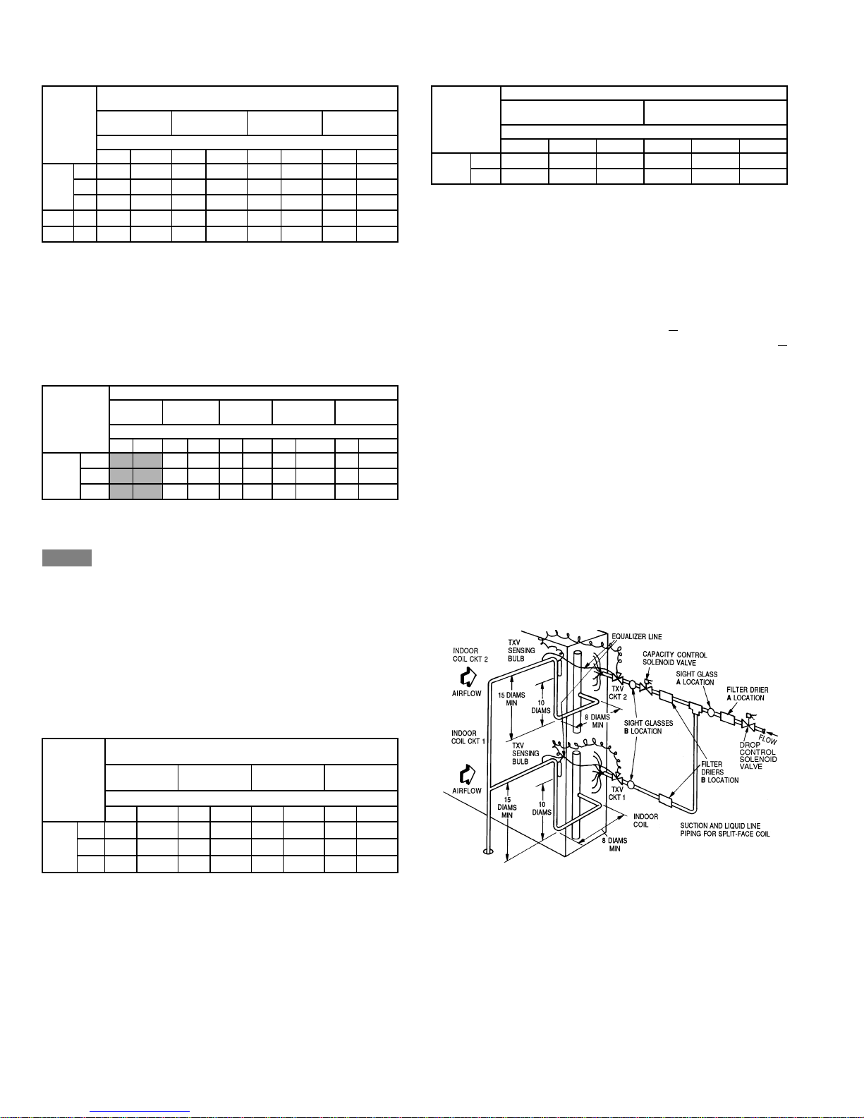
Table 3A — Refrigerant Piping Sizes —
569D, 576C, 569F Units
LINEAR LENGTH OF INTERCONNECTING PIPING —
UNIT
0-25
(0-7.5)
LSLSLSLS
072
0903/811/
569D
1201/213/
1201/213/
576C
3
/811/
8
8
8
8
3
/811/
3
/811/
1
/213/
1
/213/
569F 120 (2)3/8(2) 11/8(2)3/8(2) 11/8(2)3/8(2) 11/8(2)3/8(2) 11/
L—Liquid Line S—Suction Line
LEGEND
*Field-supplied suction accumulator required.
NOTES:
1. Pipe sizes are based on a 2 F (1 C) loss for liquid and suction lines.
2. Pipe sizes are based on the maximum linear length, shown for each
column, plus a 50% allowance for fittings.
3. Charge units with R-22 in accordance with unit installation instructions.
FT (m)
26-50
(7.8-15)
Line Size (in. OD)
8
8
8
8
51-75
(15.3-23)
3
/
8
3
/
8
1
/
2
1
/
2
11/
11/
13/
13/
76-100*
(23.3-30)
3
/811/
8
3
/811/
8
1
/213/
8
1
/213/
8
8
8
8
8
Table 3B — Refrigerant Piping Sizes —
566D Units
LENGTH OF INTERCONNECTING PIPING, FT (M)
UNIT
0-15
(0-4.5)
16-25
(4.8-7.5)
26-50
(7.8-15)
51-75
(15.3-23)
76-100*
(23.3-30)
Line Size (in. OD)
LSLSLSLSLS
566D
150
180
240
1
/211/
1
/213/
5
/815/
8
8
8
1
/213/
5
/813/
5
/815/
5
/813/
8
5
/815/
8
7
/815/
8
5
/815/8†5/815/8†
8
7
/815/
8
8
7
/821/
8
8
7
/821/8†
7
/821/
8
LEGEND
L—Liquid
S—Suction
Close-coupled
*Field-supplied suction accumulator required.
†Requires a double suction riser if 2 unloaders are used and the evaporator is
below the condensing unit. See Table 4 and Fig. 6 for more information.
NOTES:
1. Pipe sizes are based on a 2 F (1.1 C) loss for liquid lines and a 1.5 F
(0.8 C) loss for suction lines.
2. Pipe sizes are based on an equivalent length equal to the maximum
length of interconnecting piping plus 50% for fittings. A more accurate
estimate may result in smaller sizes.
3. For applications with refrigerant line lengths greater than 100 ft, contact
Bryant representative.
Table 3C — Refrigerant Piping Sizes —
566E Units
LINEAR LENGTH OF INTERCONNECTING PIPING
UNIT
0-25
(0-7.5)
LSLSLSLS
566E
1
150
/211/
1801/213/
2401/213/
8
8
8
1
/211/
1
/213/
1
/213/
LEGEND
L—Liquid
S—Suction
*Field-supplied suction accumulator required.
NOTES:
1. Pipe sizes are based on a 2 F (1.1 C) loss for liquid lines and a 1.5 F
(0.8 C) loss for suction lines.
2. Pipe sizes are based on an equivalent length equal to the maximum
length of interconnecting piping plus 50% for fittings. A more accurate
estimate may result in smaller sizes.
3. For applications with refrigerant line lengths greater than 100 ft, contact
Bryant representative.
FT (M)
26-50
(7.8-15)
Line Size (in. OD)
8
8
8
51-75
(15.3-23)
1
/211/
1
/213/
5
/813/
8
8
8
76-100*
(23.3-30)
1
/213/
5
/813/
5
/813/
8
8
8
Table 4 — Refrigerant Piping Sizes, Double Suction
Risers — 566D150, 180 Units
LENGTH OF INTERCONNECTING PIPING, FT (M)
UNIT
50-75
(15-23)
76-100
(23.3-30)
Line Size (in. OD)
ABCABC
1
/
150 1
566D
180 ———1
NOTES:
1. See Fig. 5 for “A,” “B,” and “C” dimensions.
2. No double suction risers are needed for unit size 240.
8
13/
8
15/
8
11/
8
13/
8
3
/
15/
8
15/
8
8
21/
8
8
B. Install Filter Drier(s) and Moisture Indicator(s)
Every unit should have a filter drier and liquid-moisture
indicator (sight glass). Re fer to Table 5. In so me applica tions ,
depending on spa ce and co nven ienc e requ irem ents, it may be
desirable to install 2 filter driers and sight glasses. One filter
drier and sight glass may be inst alle d at A
locations in Fi g . 7,
or, 2 filter driers and sight glasses may be installed at B
locations.
Select the filter drier for maximum unit capacity and minimum pressure drop. Complete the refrigerant piping from
indoor unit to outdoor unit before opening the liquid and
suction lines at the outdoor unit.
C. Install Liquid Line Solenoid Valve — Solenoid Drop
It is recommended that a solenoid valve be placed in the
main liquid line (se e F ig. 7) between con d ens ing u n it a nd fa n
coil. Refer to Table 5. (A liquid line soleno id va lv e is requi r ed
when the liquid line length exceeds 75 ft.) This valve
prevents refrigerant migration (which cause s oil dilution) to
the compressor during the off cycle at low outdoor ambient
temperatures. The solen oid shoul d be wired in p arallel with
the compressor contactor coil. This means of electrical
control is referred to as solenoid drop control.
LEGEND
TXV — Thermostatic Expansion Valve
Fig. 7 — Location of Sight Glass(es)
and Filter Driers
—10—
Page 11
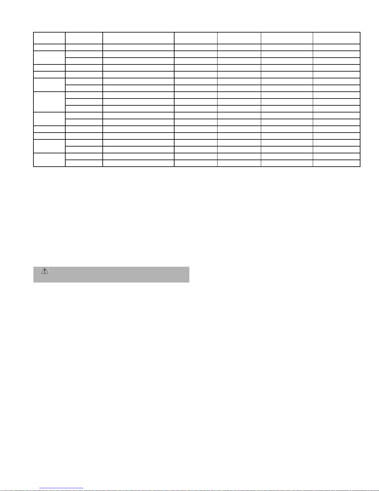
Table 5 — Refrigerant Specialities Part Numbers
UNIT
569D072
569D090
569D120
576C120
566D150
566D180
566D240
569F120
566E150
566E180
566E240
LIQUID LINE
SIZE (in.)
3
/
8
3
/
8
1
/
2
1
/
2
1
/
2
1
/
2
5
/
8
1
/
2
5
/
8
7
/
8
5
/
8
7
/
8
3
/
8
1
/
2
1
/
2
5
/
8
1
/
2
5
/
8
LIQUID LINE
SOLENOID VALVE (LLSV)
200RB5T3M AMG/24V AMI-1TT3 P502-8304S* S-7063S*
200RB5T3M AMG/24V AMI-1TT3 P502-8304S* S-7063S*
200RB5T4M AMG/24V AMI-1TT4 P502-8304S S-7063S*
200RB6T4M AMG/24V AMI-1TT4 P502-8307S* S-7063
200RB6T4M AMG/24V AMI-1TT4 P502-8307S* S-7063
200RB7T4M AMG/24V AMI-1TT4 P502-8757S* S-7063
200RA8T5M AMG/24V AMI-1TT5 P502-8757S* S-7063
200RB7T4M AMG/24V AMI-1TT4 P502-8757S* S-7721
240RA8T5M AMG/24V AMI-1TT5 P502-8757S* S-7721
200RA8T7M AMG/24V AMI-1TT7 P502-8757S S-7721
200RA9T5M AMG/24V AMI-1TT5 P502-8757S* S-7721
200RA9T7M AMG/24V AMI-1TT7 P502-8757S S-7721
200RB5T3M Qty 2 AMG/24VQty 2 AMI-1TT3 Qty 2 P502-8304S* Qty 2 S-7061 Qty 2
200RB5T4M Qty 2 AMG/24VQty 2 AMI-1TT4 Qty 2 P502-8304S Qty 2 S-7063S* Qty 2
200RB5T4M Qty 2 AMG/24VQty 2 AMI-1TT4 Qty 2 P502-8304S Qty 2 S-7063S Qty 2
200RB5T5M Qty 2 AMG/24VQty 2 AMI-1TT5 Qty 2 P502-8305S Qty 2 S-7063S Qty 2
200RB6T4M Qty 2 AMG/24VQty 2 AMI-1TT5 Qty 2 P502-8307S* S-7063S Qty 2
200RB6T5M Qty 2 AMG/24VQty 2 AMI-1TT5 Qty 2 P502-8307S* S-7063S Qty 2
*Bushings required.
D. Install Liquid Line Solenoid Valve (Optional) — Capacity
Control
If 2-step cooling is desired, place a solenoid valve in the location shown in Fig. 7.
E. Make Piping Connections
Do not remove runaround loop from suction and liquid line
stubs in the compressor compartment until piping connections are read y to be made. Pass nitroge n or other ine rt gas
through piping while brazing to prevent formation of copper
oxide.
WARNING: Recover holding charge prior to
removal of runaround piping loop.
1. Open service valves:
a. Discharge service valve on compressor.
b. Suction ser vic e valve on compressor.
c. Liquid line valve.
2. Remove
1
/4-in. flare cap from liquid valve Schrader
port.
3. Attach refrigerant recovery device and re cover hold-
ing charge.
4. Remove runaround loop.
5. Install a field-supplied liquid moisture indicator in
the piping immediately leaving outdoor unit.
6. If necessary, install field-supplied thermostatic
expansion val ve(s) (TXVs) in a ir handler.
If 2 TXVs are installed and two-step cooling is desired,
install field-supplied capacity control liquid line solenoid
valve ahead of the upper TXV (see Fig. 7).
F. Provide Safety Relief
A fusible plug is loca ted on the compressor crankcas e or in
the liquid line (Fig. 8). Do not cap this plug. If local code
requires additi onal safety devices, install them as directed.
LLSV
COIL
SIGHT
GLASS
FILTER
DRIER
SUCTION LINE
ACCUMULATOR
IV. INSTALL ACCESSORIES
Field install accessories such as low-ambient control before
proceeding with wiring. Refer to the instructions shipped
with the accessory.
V. COMPLETE ELECTRICAL CONNECTIONS
A. Power Wiring
Unit is factory wired for volta ge shown on nameplate. Provide adequate fused disconnect switch within sight from unit
and readily accessible from unit, but out of the reach of children. Lock switch open (off) to prevent power from being
turned on while unit is being serviced. Disconnect switch,
fuses, and field wiring must comply with national and local
code requirements. See Tables 6A-6C.
Route power wires through opening in unit end panel to connection in unit control box as shown on unit label diagram
and in Fig. 9. Unit must be grounded.
Affix crankcase heater warning sticker to unit disconnect
switch.
B. Control Circuit Wiring
Control voltage is 24 v. See Fig. 10 a nd unit la bel dia gram for
field-supplied wiring details. Route control wires through
opening in unit end panel to connection in unit control box.
C. Control Transformer Wiring (569D, 576C, 569F Units
Only)
On multivoltage u nits, check the transformer primary wiring connections. See Fig. 11 or refer to unit label diagram.
If unit will be operating at 208-3-60 power, remove black
wire (BLK) from the transformer primary connection
labelled “230” and move it to the connection labelled “208”.
See Fig. 11.
—11—
Page 12
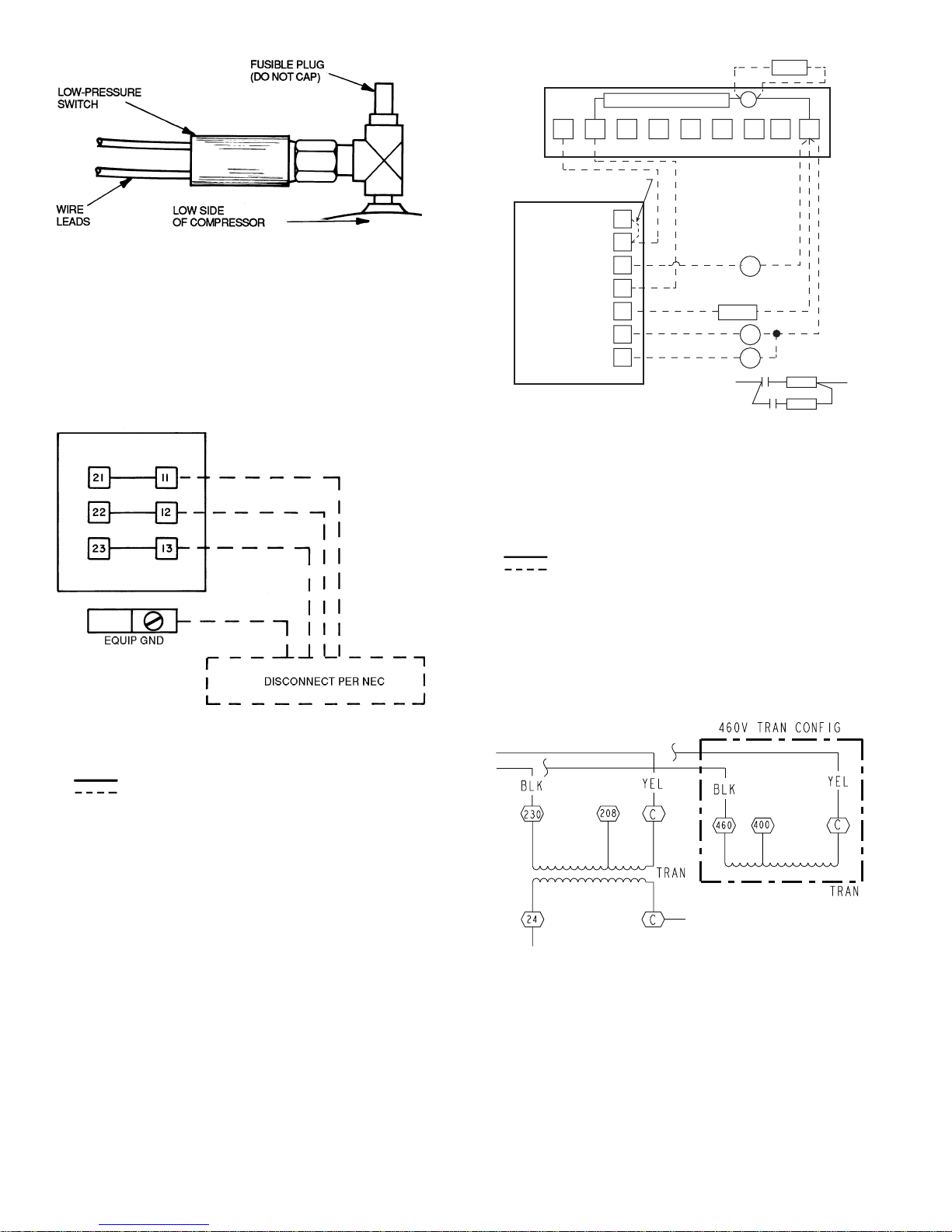
TERMINAL BOARD TB2
IN CONTROL BOX
TIME GUARD CIRCUIT
LLSV1
C
NOTES:
1. 566D240 has a fusible plug in the liquid line.
2. 569D120, 576C120 and 569F120 units have a fusible joint in the
liquid line.
Fig. 8 — Location of Fusible Plug (566D)
IFC
R1
R2
8
R1
R2
9
HD1
HD2
7
1
ACCESSORY
THERMOSTAT
2
JUMPER
RH
RC
Y2
W1
W2
Y1
4
3
G
5
NOTE 2
6
NOTE 1
LLSV2
L1
LEGEND
C—Compressor Contactor
HD — Heating Device
IFC — Indoor-Fan Contactor
LLSV1 — Liquid Line Solenoid Valve 1 — Refrigerant Migration
Control
LLSV2 — Liquid Line Solenoid Valve 2 — Capacity Control
R—Relay
Factory Wiring
Field Wiring
NOTES:
1. Combination LLSV plus IFC va should not exceed 30 va.
2. Do not exceed 5 va (24 vac) per coil.
3. If va values shown in Notes 1 and 2 must be exceeded, use
accessory relay transformer package 38AE900001 (60 Hz).
Fig. 10 — Typical Remote Thermostat Wiring
(566D Unit Shown)
L2
LEGEND
EQUIP GND — Equipment Ground
NEC — National Electrical Code
Fac to ry Wiring
Field Wiring
NOTE: Terminal block (TB1) is used for 566E150-240 and 566D150240 units. Pigtails are provided on 569D, 576C, 569F units.
Fig. 9 — Main Power Supply Wiring
(566D Unit Shown)
Fig. 11 — Control Transformer Wiring
(569D, 576C, 569F Unit Shown)
—12—
Page 13
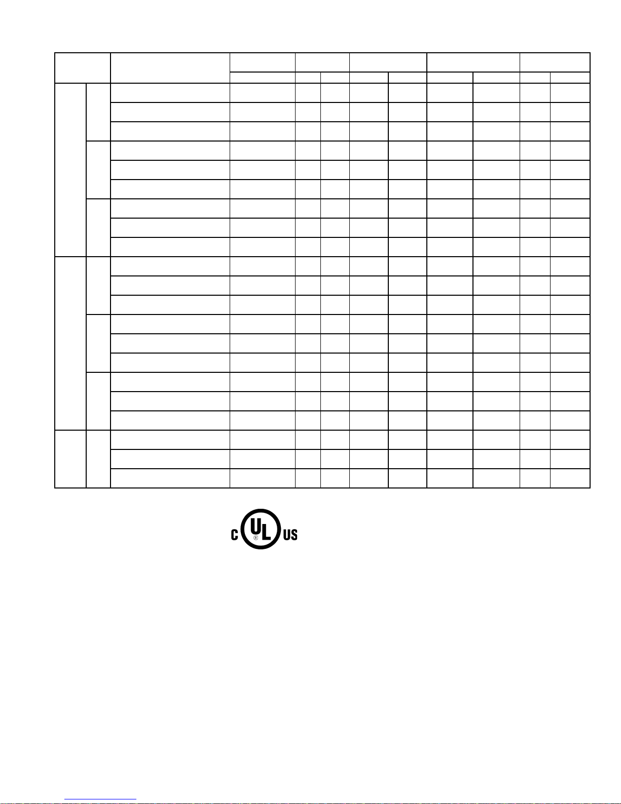
Table 6A — Electrical Data — 569D072-120, 576C090-120, 569F120 Units
UNIT
SIZE
072
569D
576C
569F 120
FLA — Full Load Amps
LRA — Locked Rotor Amps
MCA — Minimum Circuit Amps
MOCP — Maximum Overcurrent Protection
NEC — National Electrical Code
RLA — Rated Load Amps
090
120
090
102
120
LEGEND *Units are suitable for use on electrical systems where voltage supplied
FACTORY
INSTALLED
OPTION
NONE OR DISCONNECT
CONVENIENCE OUTLET 30.6 35
NONE OR DISCONNECT
CONVENIENCE OUTLET 15.0 20
NONE OR DISCONNECT
CONVENIENCE OUTLET 12.0 15
NONE OR DISCONNECT
CONVENIENCE OUTLET 39.8 60
NONE OR DISCONNECT
CONVENIENCE OUTLET 19.6 30
NONE OR DISCONNECT
CONVENIENCE OUTLET 15.5 20
NONE OR DISCONNECT
CONVENIENCE OUTLET 55.1 70
NONE OR DISCONNECT
CONVENIENCE OUTLET 25.1 30
NONE OR DISCONNECT
CONVENIENCE OUTLET 19.5 25
NONE OR DISCONNECT
CONVENIENCE OUTLET 43.1 60
NONE OR DISCONNECT
CONVENIENCE OUTLET 21.2 25
NONE OR DISCONNECT
CONVENIENCE OUTLET 16.9 20
NONE OR DISCONNECT
CONVENIENCE OUTLET 52.8 70
NONE OR DISCONNECT
CONVENIENCE OUTLET 26.1 35
NONE OR DISCONNECT
CONVENIENCE OUTLET 20.3 30
NONE OR DISCONNECT
CONVENIENCE OUTLET 52.8 70
NONE OR DISCONNECT
CONVENIENCE OUTLET 26.1 35
NONE OR DISCONNECT
CONVENIENCE OUTLET 20.3 30
NONE OR DISCONNECT
CONVENIENCE OUTLET 43.8 55
NONE OR DISCONNECT
CONVENIENCE OUTLET 21.6 25
NONE OR DISCONNECT
CONVENIENCE OUTLET 17.5 20
NOMINAL
VO LTAGE
V-Ph-Hz Min Max RLA LRA FLA (ea) LRA (ea) MCA MOCP
208/230-3-60 187 254 19.2 146 0.9 1.6
460-3-60 418 506 9.6 73 0.4 0.9
575-3-60 523 632 7.7 58.4 0.4 0.9
208/230-3-60 187 254 25.6 190 1.5 3.1
460-3-60 418 506 12.8 95 0.7 1.9
575-3-60 523 632 10.2 76 0.7 1.9
208/230-3-60 187 254 37.8 239 1.5 3.1
460-3-60 418 506 17.2 125 0.7 1.9
575-3-60 523 632 13.4 80 0.7 1.9
208/230-3-60 187 254 28.2 160 1.5 3.1
460-3-60 418 506 14.1 80 0.7 1.9
575-3-60 523 632 11.3 64 0.7 1.9
208/230-3-60 187 254 36 198 1.5 3.1
460-3-60 418 506 18 99 0.7 1.9
575-3-60 523 632 14 79 0.7 1.9
208/230-3-60 187 254 36 198 1.5 3.1
460-3-60 418 506 18 99 0.7 1.9
575-3-60 523 632 14 79 0.7 1.9
208/230-3-60 187 254 16 125 1.5 3.1
460-3-60 418 506 8 66.5 0.7 1.9
575-3-60 523 632 6.4 50 0.7 1.9
VO LTAGE
RANGE*
COMPRESSOR
to the unit terminals is not below or above the listed limits.
NOTES:
1. The MCA and MOCP values are calculated in accordance with the
NEC, Article 440.
2. Motor RLA and LRA values are established in accordance with
Underwriters’ Laboratories (UL), Standard 1995.
3. The 575-v units are UL, Canada-listed only.
4. Convenience outlet is available as either a factory-installed option or
a field-installed accessory and is 115-v, 1 ph, 60 Hz.
FAN MO TOR S
(Qty 2)
POWER
SUPPLY
25.8 35
12.8 20
10.2 15
35.0 60
17.4 30
13.8 20
50.3 60
22.9 30
17.8 25
38.3 60
19.0 25
15.2 20
48.0 60
23.9 35
18.6 30
48.0 60
23.9 35
18.6 30
39.0 55
19.4 25
15.8 20
—13—
Page 14
Table 6B — Electrical Data — 566D150-240 Units
UNIT
150
566D
FLA — Full Load Amps
HACR — Heating, Air Conditioning and
ICF — Maximum Instantaneous Current Flow
kW — Total Fan Motor Input (kilowatts)
LRA — Locked Rotor Amps
MCA — Minimum Circuit Amps per NEC,
MOCP — Maximum Overcurrent Protection (amps)
RLA — Rated Load Amps (compressor)
180
240
Refrigeration
During Start-Up (LRA of compressor
plus total FLA of fan motors)
Section 430-24
NOMINAL
VOLTAGE
(3-Ph, 60 Hz)
208/230 187 253 49.3 191 4.3 3.7
460 414 528 22.1 80 2.3 1.9 31.7 50 84
575 518 660 17.9 69 1.8 1.8 25.6 40 73
208/230 187 253 63.6 266 4.3 3.7
460 414 528 29.3 120 2.3 1.9 40.7 60 124
575 518 660 23.8 96 1.8 1.8 33.0 50 100
208/230 187 254 67.9 345 4.3 3.7
460 414 508 34.7 173 2.3 1.9 48.1 80 177
575 518 632 28.8 120 1.8 1.8 40.1 60 124
LEGEND *Units are suitable for use on electrical systems where voltage sup-
VO LTAGE
RANGE*
Min Max 1 2
Table 6C — Electrical Data — 566E150-240 Units
UNIT
150
180
566E
240
FLA — Full Load Amps
HACR — Heating, Air Conditioning and
ICF — Maximum Instantaneous Current Flow
kW — Total Fan Motor Input (kilowatts)
LRA — Locked Rotor Amps
MCA — Minimum Circuit Amps per NEC,
MOCP — Maximum Overcurrent Protection (amps)
RLA — Rated Load Amps (compressor)
Refrigeration
During Start-Up (LRA of compressor
plus total FLA of fan motors)
Section 430-24
FACTORY-
INSTALLED
OPTION
NONE OR DISCONNECT
CONVENIENCE OUTLET
NONE OR DISCONNECT
CONVENIENCE OUTLET
NONE OR DISCONNECT
CONVENIENCE OUTLET
NONE OR DISCONNECT
CONVENIENCE OUTLET
NONE OR DISCONNECT
CONVENIENCE OUTLET
NONE OR DISCONNECT
CONVENIENCE OUTLET
NONE OR DISCONNECT
CONVENIENCE OUTLET
NONE OR DISCONNECT
CONVENIENCE OUTLET
NONE OR DISCONNECT
CONVENIENCE OUTLET
LEGEND *Units are suitable for use on electrical systems where voltage sup-
NOMINAL
VO LTAGE
(3 Ph, 60 Hz)
208/230 187 253 20.7 156 20.7 156 4.3 3.7 1.41
460 414 528 10.0 75 10.0 75 2.3 1.9 1.41
575 518 660 8.2 54 8.2 54 1.8 1.8 1.41
208/230 187 253 32.1 195 32.1 195 4.3 3.7 1.41
460 414 528 16.4 95 16.4 95 2.3 1.9 1.41
575 518 660 12.0 80 12.0 80 1.8 1.8 1.41
208/230 187 253 37.8 239 37.8 239 4.3 3.7 1.41
460 414 528 19.2 125 19.2 125 2.3 1.9 1.41
575 518 660 13.8 80 13.8 80 1.8 1.8 1.41
COMPRESSOR FAN MOTORS (Qty 2) POWER SUPPLY
FLA (ea)
RLA LRA
†Fuse or HACR circuit breaker.
NOTES:
1. The MCA and MOCP values are calculated in accordance with the
2. Motor RLA and LRA values are established in accordance with
3. The 575-v units are UL, Canada-listed only.
VOLTAGE
RANGE*
Min Max RLA LRA RLA LRA 1 2 MCA MOCP† ICF
COMPRESSOR 1 COMPRESSOR 2
†Fuse or HACR circuit breaker.
NOTES:
1. The MCA and MOCP values are calculated in accordance with the
2. Motor RLA and LRA values are established in accordance with
3. The 575-v units are UL, Canada-listed only.
Fan No.
plied to the unit terminals is not below or above the listed limits.
National Electrical Code (NEC), Article 440.
Underwriters’ Laboratories (UL), Standard 1995.
plied to the unit terminals is not below or above the listed limits.
National Electrical Code (NEC), Article 440.
Underwriters’ Laboratories (UL), Standard 1995.
kW MCA MOCP† ICF
1.41
1.41
1.41
FAN MOTORS (Qty 2)
FLA (ea)
Fan No.
69.6 100 199
87.5 125 274
93.4 150 353
POWER
kW
SUPPLY
55.6 70 186
63.5 80 194
27.7 35 90
31.3 40 94
23.1 30 67
25.9 30 70
81.2 100 236
89.2 100 244
42.1 50 117
45.7 60 120
31.6 40 97
34.5 40 99
94.1 125 286
102.0 150 294
48.4 60 149
52.0 70 153
35.7 45 98
38.5 50 101
—14—
Page 15

PRE-START-UP
IMPORTANT: Before beginning Pre-Start-Up or Start-Up,
review Start-Up Checklist at the back of this book. The
Checklist assures proper start-up of a unit and pr ovides a
record of unit condition, application requirements, system
information, and operation at initial start-up.
CAUTION: Do not attempt to start the conde nsing
unit, even momentarily, until the following steps have
been completed. Compressor damage may result.
I. SYSTEM CHECK
1. Check all air handler(s) and other equipment auxiliary components. Consult the manufacturer’s instructions regarding any other equipment connected to the
condensing unit. If unit has field-installed accessories, be sure all are properly installed a nd correctly
wired. If used, airflow switch must be properly
installed.
2. Backseat (open) compressor suction and discharge
valves. Now close valves one turn to allow refrigerant
pressure to reach test gages.
3. Open liquid lin e service valve.
4. Check tightness of all electrical connections.
5. For 576C, 566D units only, compressor oil level
should be v isible in sight glass. Ref er to Ch eck Compressor Oil Level. Adjust the oil level as required.
Refer to Start-Up, Preliminary Oil Charge section.
No oil should be removed unless the crankcase heater
has been energized for at least 24 hours.
6. Be sure unit is properly leak checked, dehydrated,
and charged. See Preliminary Charge, this page.
7. Electrical power source must agree with nameplate
rating.
8. Crankcase heater must be firmly locked into compres-
sor crankcase. Be sure crankcase is warm (heater
must be on for 24 hours before starting compressor).
9. Be sure compressor floats freely on the mounting
springs and that snubber washers can be moved with
finger pressure. See Compressor Mounting, page 9,
and Fig. 5 for loosening compressor bolts.
II. LEAK TEST AND DEHYDRATION
Leak test the entire refrigerant sys tem using soap bubbles
and/or an electr onic leak detector. Evacuate and dehydrate
entire refrigerant system.
III. TURN ON CRANKCASE HEATER
Turn on crankcase heater for 24 hours before starting the unit
to be sure all the refrigerant is out of th e oil. To energize the
crankcase heater, proceed as follows:
1. Set the space thermostat set point above the space
temperature so there is no demand for cooling.
2. Close the field disconnect.
3. Turn the fan circ uit breaker on. Le ave the compressor circuit breake rs off. The crankcase heater is now
energized.
IV. PRELIMINARY CHARGE
Before starting the unit, charge liquid refrigerant into the
high side of the system through the liquid service valve. The
amount of refrigerant added must be at least 80% of the
operating charge listed in the Physical Data table (Tables
1A-1C, pages 6-8). Allow high and low side pressures to
equalize before starting compressor. If pressures do not
equalize readily, charge vapor on low side of system to assure
charge in the ev aporat or. Refer to GTAC II, Modul e 5, Char ging, Recover, Recycling, and Reclamation for liquid charging
procedures.
CAUTION: Prior to starting compressor, refrigerant equal to operating charge must be added to avoid
possible compressor damage. See Tables 1A-1C.
START-UP
I. 569D, 566E, 569F UNITS
Compressor crankcase heater must be on for 24 ho ur s bef ore
start-up. After the heater has been on for 24 hours, the unit
can be started. If no time has elapsed since the preliminary
charge step has been completed, it is unnecessary to wait the
24-hour period.
A. Preliminary Checks
1. Ensure that compressor service valves are backseated.
2. Verify that each compressor floats freely on its
mounting springs.
3. Check that electric power supply agrees with unit
nameplate data.
4. Verify that compressor cr ankcase heater is securel y
in place.
5. Check that compres sor cr ankc ase heat er has b een on
at least 24 hours.
6. Recheck for leaks using same procedure as previously
outlined in Pre-Start-Up section, Leak Test and
Dehydration.
7. If any leaks are detected, evacuate and dehydrate as
previously outlined in Pre-Start-Up section, Leak
Test and Dehydration.
8. All internal wiring connections must be tight, and all
barriers and covers mu st be in place.
NOTE: The 569D , 566E, 56 9F units do no t ha ve a compr essor
oil level sight glas s . Th ese uni ts ar e fact ory chan ged wit h the
required amount of oil . If recharging is required, us e Zerol
150 for the 569F, 569D072, and 569D090. Use Replacement
Components Division Oil (P/N P903-0101) for the 569D120
and 566E150-240.
B. Compressor Rotation
On 3-phase units with scroll compressors, it is important to
be certain compressor is rotating i n the proper direc tion. To
determine whether or not compressor is rotating in the
proper direction:
1. Connect service gages to suct ion and discharge pressure fittings.
2. Energize the compressor.
3. The suction pressure should drop and the discharge
pressure should rise, as is normal on any start-up.
If the suction pressure does not drop and the discharge
pressure does not rise to normal levels:
1. Note that the condenser fan is probably also rotating
in the wrong direction.
2. Turn off power to the unit, tag disconnect.
3. Reverse any two of the unit power leads.
4. Reapply power to the compressor, verify correct
pressures.
The suction and discharge pressure levels should now move
to their normal start-up levels.
—15—
Page 16
C. Compressor Overload
This overload interrupts power to the compressor when
either the current or internal motor winding temperature
becomes excessive, and automatically resets when the internal temperature drops to a safe level. This overload may
require up to 60 minutes (or longer) to reset. If the internal
overload is sus pect ed of be ing op en, di sconn ect the elect ric al
power to the unit and check the circuit through the overload
with an ohmmeter or continuity tester.
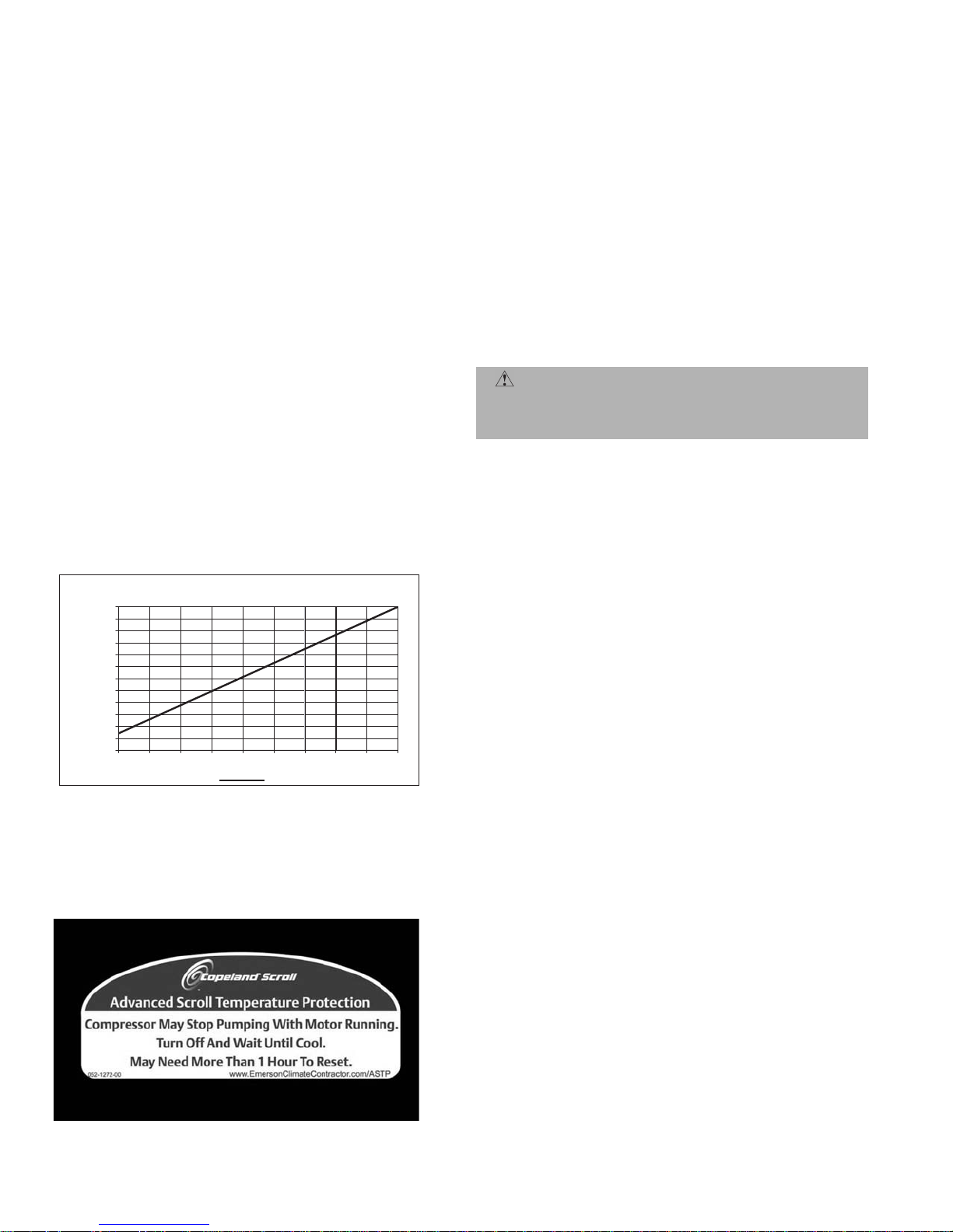
D. Advanced Scroll Temperature Protection (ASTP)
Advanced Scroll Temperature Protection (ASTP) is a form of
internal dischar ge temperature protecti on that unloads the
scroll compressor when the internal temperature reaches
approximately 300 F. At this temperature, an internal bimetal disk valve opens and ca use s t he sc ro ll elements to sep arate, which stops compression. Suction and discharge pressures balance while the motor continues to run. The longer
the compressor runs unloade d, the l onge r it m ust co ol be fore
the bi-metal disk resets. See Fig. 12.
To manually reset ASTP, the compressor should be stopped
and allowed to cool. If the compressor is not stopped, the
motor will run un til the motor prote ctor trips, which occurs
up to 90 minutes later. Advanced Scroll Temperature Protection will reset automatically before the motor protector
resets, which may take up to 2 hours. A label located above
the terminal box identifies Copeland Scroll compressor
models (ZR94, 108 and 125) that contain t his technology. See
Fig. 13.
120
110
100
90
80
es)
70
nut
60
50
(Mi
40
30
20
Recommended Cooli ng Time
10
0
0 102030405060708090
*Times are approximate.
NOTE: Various factors, including high humidity, high ambient tempera-
ture, and the presence of a sound blanket will increase cool-down
times.
Compressor Unloaded Run Time (Minutes)
Fig. 12 — Recommended Minimum Cool-Down Time After
Compressor is Stopped*
E. Compressor Lockout Device
The compressor lockout (CLO) device pre vents the compres sor from starting or running in a high pressure, loss-ofcharge or freeze-stat open situation. Reset the CLO device by
setting the thermostat to eliminate cooling demand and
return it to the original se t point. If the system shut s down
again for the same fault, determine the possible cause before
attempting to reset the CLO device.
F. S ta r t Un it
The field disconnect is closed, the fan circuit breaker is
closed, and the sp ac e therm osta t is set above am bient so that
there is no demand for cooling. Only the crankcase heater
will be energized.
Next, reset space thermostat below ambient so that a call for
cooling is ensured.
NOTE: Do not use circuit breaker to star t and stop the compressor except in an emergency.
CAUTION: Never charge liquid into the low-pressure
side of system. Do not overcharge. During charging or
removal of refrigerant, be sure indoor-fan system is
operating.
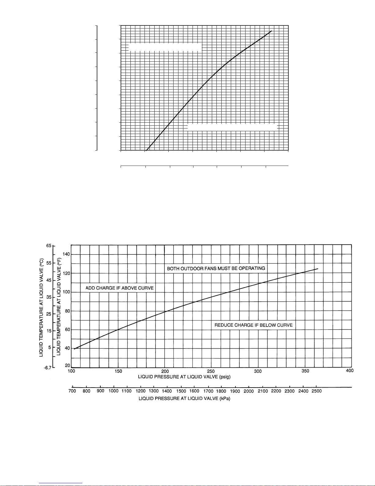
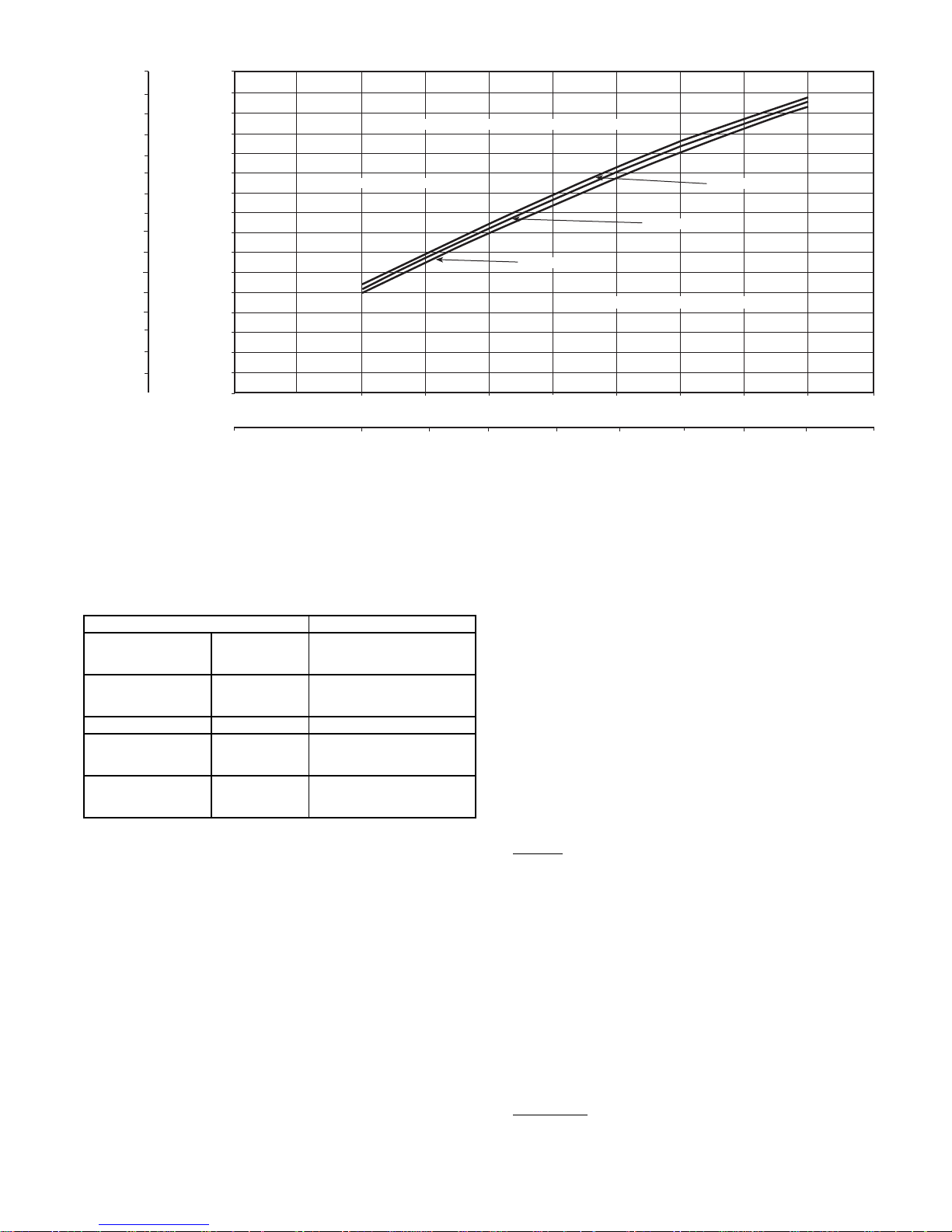
G. Adjust Refrigerant Charge
Unit must be charged in Cooling mode only. Refer to Cooling
Charging Charts, Fig. 14-18 and to Table 7 for maximum
charge level. Do not exceed maximum refrigerant charge. For
applications with line lengths greater than 100 ft, contact
Bryant representative. Vary refrigerant until the conditions
of the chart are met. Note that charging charts are di fferent
from type normally use d. Charts a re based on charging t he
units to the correct subcoo ling for th e variou s operati ng conditions. Accurate pressure gage and temperature sensing
device are required. Connect the pressure gage to the service
port on the liquid line service valve. Mount the temperature
sensing device on the liquid line, close to the liquid line service valve and insulate it so that outdoor ambient temperature does not affect the reading. Indoor airflow must be
within the normal operating range of the unit. Operate unit
a minimum of 15 min ut es. Ensure pressure a nd t e mpe rat ure
readings have stabilized. Plot liquid pressure and temperature on chart and add or reduce charge to meet curve. Adjust
charge to conform with charging chart, using the liquid pressure and temperature to read chart.
If the liquid line sight glass is cloudy, check refrigerant charge
again. Ensure all fans are operating. Also ensure maximum
allowable liquid lift has not been exceeded. If charged per
chart and if the sight glass is sti ll cloudy, check for a plugged
filter drier or a partially closed solenoid valve. Replace or
repair, as needed.
Fig. 13 — Advanced Scroll Temperature Protection Label
—16—
Page 17
60
140
LIQUID TEMPERATURE AT LIQUID VALVE (C)
54
49
43
38
32
27
21
16
10
LIQUID TEMPERATURE AT LIQUID VALVE (F)
130
120
110
100
ADD CHARGE IF ABOVE CURVE
90
80
70
60
50
50
344
100
689
150 200 250 300 350 400
LIQUID PRESSURE AT LIQUID VALVE (PSIG)
1034
LIQUID PRESSURE AT LIQUID VALVE (Kilopascals)
REDUCE CHARGE IF BELOW CURVE
1379
1724
2069
2414
Fig. 14 — 569D072-120, 569F120, 576C090-120 Charging Chart
Fig. 15 — 566D150 Charging Chart
—17—
Page 18
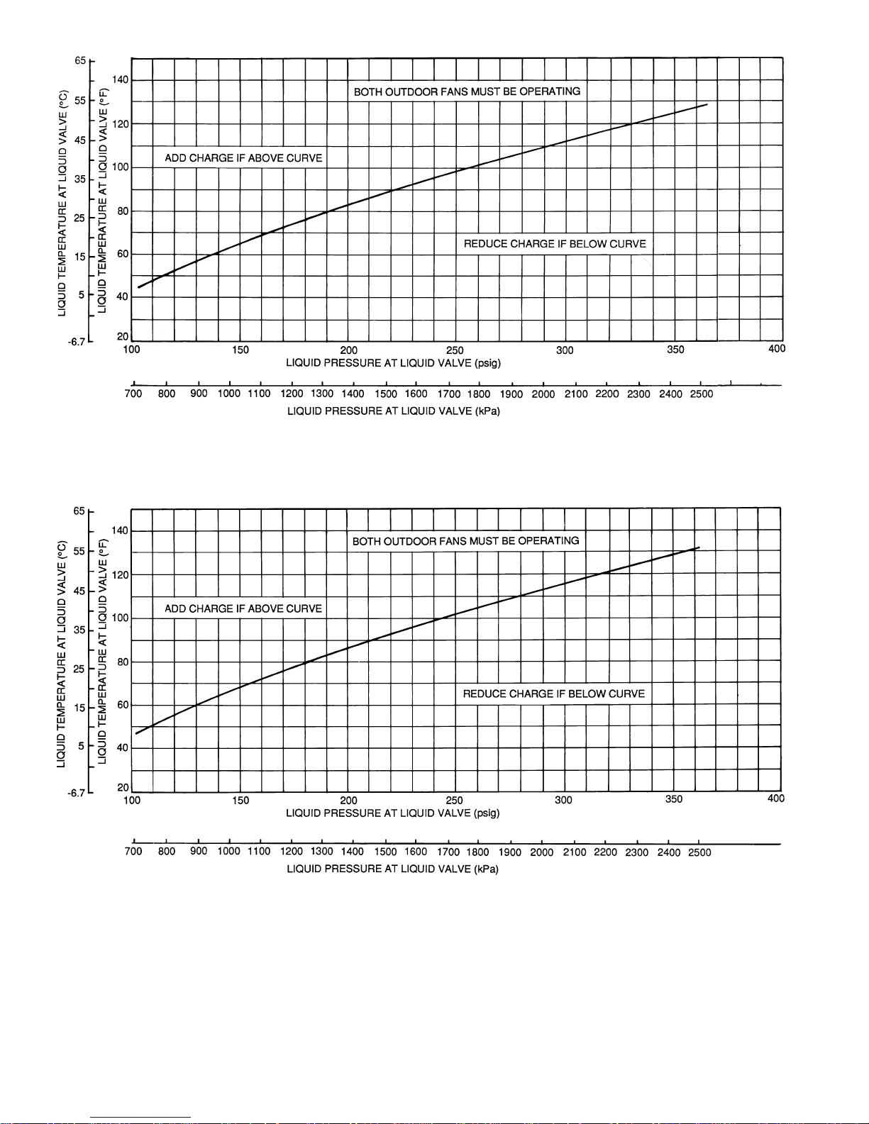
Fig. 16 — 566D180 Charging Chart
Fig. 17 — 566D240 Charging Chart
—18—
Page 19
LIQUID TEMPERATURE AT LIQUID VALVE (C)
60
43
10
-12
LIQUID TEMPERATURE AT LIQUID VALVE (F)
160.00
150.00
140.00
130.00
120.00
110.00
100.00
90.00
80.00
70.00
60.00
50.00
40.00
30.00
20.00
10.00
0.00
BOTH OUTDOOR FANS MUST BE OPERATING
ADD CHARGE IF ABOVE CURVE
100
690
150
LIQUID PRESSURE AT LIQUID VALVE (psig)
1030
LIQUID PRESSURE AT LIQUID VALVE (kPa)
200
1379
566E150
250 300
1720
556E240
566E180
REDUCE CHARGE IF BELOW CURVE
350 400
2069
2410
2758
450 500
3100
3448
71
66
64
49
38
32
27
21
16
4
-1
-7
Fig. 18 — 566E150-240 Charging Chart
H. Final Checks
Ensure all safety contro ls are operating, control panel covers
are on, and the s e rvice panels are in place.
Table 7 — Maximum Refrigerant Charge
UNIT R-22 (lb)
569D
576C
569F 120 (2) 17.1
566D
566E
NOTE: 569F120 has 2 charges, one per circuit.
072
090
120
090
102
120
150
180
240
150
180
240
17.3
34.2
34.2
34.2
40.3
39.8
39.8
48.0
II. 576C, 566D UNITS
Compressor crankcas e heater must be on for 24 hours before
start-up. After th e heater h as been o n for 24 h ours, the uni t
can be started. If no time has ela psed since the preliminary
charge step has been completed, it is unnecessary to wait the
24-hour period.
A. Preliminary Checks
1. Ensure that compressor service valves are backseated.
2. Verify that each compressor floats freely on its
mounting springs.
3. Check that electric power supply agrees with unit
nameplate data.
4. Verify that compress or crankcase heater is securely
in place.
5. Check that compres sor cr ankc ase heat er has b een on
at least 24 hours.
6. Note that compressor oil level is visible in the sight
glass.
7. Recheck for leaks using same procedure as previously
outlined in Pre-Start-Up section, Leak Test and
Dehydration.
8. If any leaks are detected, evacuate and dehydrate as
previously outlined in Pre-Start-Up section, Leak
Test and Dehydration.
9. All internal wiring connections must be tight, and all
barriers and covers mu st be in place.
B. Preliminary Oil Charge
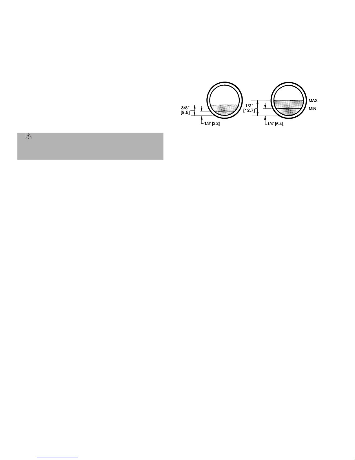
Compressor is f actory charged with oil (s ee Tables 1A-1C).
When oil is ch eck ed at start- up , i t may be ne cessar y to a dd or
remove oil to bring it to the proper level . One recommended
oil level adjustment method follows:
Add Oil
Close suction service valve and pump down crankcase to
2 psig. (Low-pressure switch must be jumpered.) Wait a few
minutes and repeat until pressure remains steady at 2 psig.
Remove oil fill plug above the oil level sight glass, add oil
through plug hole, and replace plug. Run compressor for
20 minutes and check oil level. See Fig. 19.
NOTE: Use onl y Bryant approved compressor oi l. Approved
sources are:
Petroleum Specialties Inc.. . . . . . . . . . . . . . . . . . . Cryol 150A
Texaco, Inc.. . . . . . . . . . . . . . . . . . . . . . . . . . . . Capella WF-32
Witco Chemical Co. . . . . . . . . . . . . . . . . . . . . . . . .Suniso 3GS
Do not use oil that has been drained out, or oil that has been
exposed to atmosphere.
Remove Oil
Pump down compressor to 2 psig. Loosen the 1/4-in. pipe plug
at the compressor base and all ow the o il to seep o ut pa st the
threads of the plug.
—19—
Page 20
NOTE: The crankcase will be slightly pressurized. Do not
remove the plug, or the entire oil charge will be lost.
Small amounts of oil can be removed through the oil pump
discharge connection while the compressor is running.
C. Start Unit
The field disconnect is closed, the fan circuit breaker is
closed, and the s pace the rmos tat is se t abov e ambi ent so t hat
there is no demand for cooling. Only the crankcase heater
will be energized.
Next, close the compressor circuit breaker and then reset
space thermostat below ambient so that a call for cooling is
ensured.
NOTE: Do not use circu it breake r to st art and stop the compressor except in an emergency.
After starting, there is a delay of at least 3 seconds before
compressor starts.
CAUTION: Never charge liq uid into the low-pressure side of system. Do not overcharge. During charging or removal of refrigerant, be sure indoor-fan
system is operating.
stops. The unloader is now at 0 psig set point. If electric actuated unloaders are installed, energize the solenoid to unload
the compressor.
Return unloader to original setting after checks are complete.
F. Final Checks
Ensure all safety controls are operating, control panel covers
are on, and the service panels are in place.
566D240
(06E COMPRESSOR)
566D150,180 AND
576C090-120
(06D COMPRESSOR)
Fig. 19 — Operating Oil Levels
D. Adjust Refrigerant Charge
Unit must be charged in Cooling mode only. Refer to Cooling
Charging Charts, Fig. 14-18 and to Table 7 for maximum
charge level. Vary refrigerant until the conditions of the
chart are met. Note that charging charts are different from
type normally used. Charts are based on charging the units
to the correct subcooling for the various operating conditions.
Accurate pressure gage a nd temperature sensing dev ice are
required. Connect the pressure gage to the service port on
the liquid line service valve. Mount the temperature sensing
device on the liquid line, close to the liquid line service valve
and insulate it so that outdoor ambient temperature does not
affect the reading. Indoor airflow mus t be wit hin th e normal
operating range of the unit. Operate unit a minimum of
15 minutes. Ensure pressure and temperature readings have
stabilized. Plot liquid pressure and temperature on chart
and add or reduce charge to meet curve. Adjust charge to
conform with charging chart, using the liquid pressure and
temperature to read chart.
If the sight glass is cloudy, check refrigerant charge again.
Ensure all fans are operating. Also ensure ma ximum allowable liquid lift has not been exceeded. If charged per chart
and if the sight glass is still cloudy, check for a plugged filter
drier or a partially closed solenoid valve. Replace or repair,
as needed.
E. Check Compressor Oil Level
After adjusting the refrigerant charge, allow the compressor
to run fully loaded for 20 minutes. Running oil level should
be within view of the crankcase sight glass. Stop the compressor at the field power supply disconnect and check the
crankcase oil level. Add oil only if necessary to bring the oil
into view in the sight glass. If oil i s added, run t he compressor for an additional 10 minutes, then stop and check oil
level. If the level remains low, check the piping system for
proper design for oil return; also, check the system for leaks.
If the initial check shows too much oil (too high in the sight
glass) remove oil to proper level. See Preliminary Oil
Charge, this page, for proper procedure for adding and
removing oil. See Fig. 19.
When the above checks are complete, repeat the procedure
with the unit operating at minimum load conditions.
Unload the compressor by turning the control set point
adjustment nut counterclockwise until the adjustment nut
OPERATING SEQUENCE
I. COOLING
A. 569D072-120, 576C090-120 Cooling
At start-up, the thermostat calls for cooling. With all safety
devices satisfied, the compressor contac tor and fan contacto r
energize, causing the compressor and outdoor-fan motor to
operate. Contacts energize, allowing the field-supplied and
field-installed indoor-fan contactor to function. A fieldsupplied and field-installed liquid line valve also opens,
allowing the system to function in Cool ing mode. As cooling
demand is satisfied, the thermostat c ontacts break, deenergizing the contactor and causing the system to shut off. The
liquid line solenoid valve closes, minimizing the potential for
refrigerant migratio n. The compressor does not rest art until
the thermostat again calls for cooling. The system is protected with a safety circuit so that the system will not start if
a fault exists (i.e., high-pressure or discharge gas temperature [569D090 and 120 only] fault). To reset the safety circuit, set the thermostat to eliminate the cooling demand,
then return to original set point. This should be done only
once, and if system shuts down due to the same fault, determine the problem before attempting to restart the system.
B. 566D150-240 Cooling
When the first sta ge of cooling thermostat closes, the ti mer
starts. After approximately 3 seconds, the timer activates
the compressor and fan motor no. 1 contactors. When the liquid pressure builds to approximately 257 psig, fan motor
no. 2 is energized.
When there is demand for additional cooling capacity, the
second stage of the cooling thermostat closes, energizing a
field-supplied liquid line solenoid (LLS) valve, which opens.
This increases the suction pressure, causing the compressor
to operate at higher capacity (compressor loads).
When the fan switch is set at AUTO, the indoor-air fan cycles
with the compressor. When the switch is set at CONT, the
indoor-air fan runs continuously.
At shutdown, the Time Guard II timer prevents the compressor from restarting for approxi mately 5 minutes.
In addition, an LLS valve wired in parallel with the compressor contactor coil shuts off the liquid line to prevent
—20—
Page 21
refrigerant migration back to the compressor duri ng the off
cycle.
C. 569F120 Cooling
When the thermost at calls for stag e one cooling at s tart-up,
and all safety devices are satisfied, the compressor contactor
no. 1 (C1) energizes causing compress or no. 1 and outdoorfan motor no. 1 to start (the indoor-fan contactor should be
wired to start at the same time as the compressor ). The liquid line solenoid (LLS) valve will open when compressor
no. 1 starts, allowing refrigerant to flow in the system.
When the thermostat calls for sta ge two cool ing, compresso r
contactor no. 2 (C2) energizes causing compressor no. 2 and
outdoor-fan motor no. 2 to start. As the cooling demand
decreases, stage two on the thermostat opens, causing compressor no. 2 and outdoor-fan motor no. 2 to shut down. As
the cooling continu es to decrease, stage one of the thermostat opens caus ing compressor no. 1 and outdoor-fan motor
no. 1 to shut down. The LLS valve for each co mpressor will
close when the associated compressor stops, minimizing the
potential for refrigerant migration during the off cycle.
The indoor-fan motor will stop if the thermostat is set to
AUTO and will continue to operate if the thermostat is set to
CONT. Each compressor is protected with a CLO
device so
that the compressor will not operate if there is a highpressure fault, low pressure fault, or a compressor is off due
to internal line break overcurrent/over temperature protection. To reset the CLO device, set the thermostat higher to
remove the cooling demand, then return to the original set
point. This should be done only once. If the system shuts
down with the same fault, the cause for the fault should be
determined and corrected before the a CLO device is reset
again.
D. 566E150-240 Cooling
At start-up, when the thermostat calls for first stage cooling
and all safety devices are satisfied, the compressor contactor
(C1) energizes causing compressor no. 1 and fan motor no. 1
to start. Fan motor no. 2 will start when the fan cycling pressure switch (FCPS) closes as discharge pressure builds. With
the indoor-fan contactor wired to TB2-4 and TB2-9 contacts
on the terminal block, the indoor-fan will also start wit h the
compressor. The liquid line solenoid (LLS) valve will open
when compressor no. 1 starts, allowing refrigerant to flow in
the system.
When the thermostat calls for sta ge two cool ing, compresso r
contactor no. 2 (C2) energizes causing compressor no. 2 to
start. As the cooling demand decreases, stage two on the
thermostat opens, causing compressor no. 2 to shut down. As
the cooling continu es to decrease, stage one of the thermostat opens caus ing compressor no. 1 and outdoor-fan motor
to shut down. The LLS valve fo r each compressor will close
when the associated compressor stops, minimizing the
potential for refrigerant migration during the off cycle.
The indoor-fan motor will stop if the thermostat is set to
AUTO and wi ll co ntin ue to oper ate if the ther mostat is s et o n
CONT. Each compressor is controlled by the thermostat so
they will not start until there is a demand from the thermostat. Each compressor is protected with a CLO
device so that
the compressor will not operate if there is a high-pressure
fault, low-pressure fault, or compressor is off due to internal
line break overc urrent/overtemp erature protectio n. To reset
the a CLO device, set the thermostat higher to remove the
cooling demand, then return to the original set point. This
should be done only once. If the syste m sh uts do wn wi th the
same fault, the cause for the fault should be determined and
corrected before the a CLO device is reset again.
II. HEATING
The heating thermostat (TH) energizes a field-supplied relay
which operates heating controls and energizes the indoor
unit relay. When the fan switch is set at AUTO, the indoor
unit fan cycles with the heating control. The indoor unit fan
runs continuously when the fan switch is set at ON.
Causes of complete unit shutdown are: interruption of
supplied power, open compressor internal protector (IP),
open control circuit breaker, or an open high-pressure or
low-pressure safety switch.
SERVICE
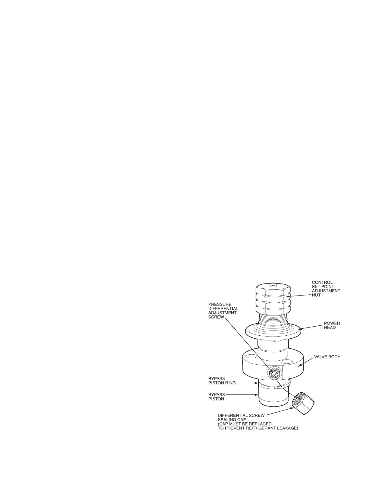
I. CAPACITY CONTROL (576C, 566D UNITS)
A suction pressure-actuated unloader controls 2 cylinders
and provides capacity contr ol. Unlo aders are fa ctory set (see
Tables 1A-1C), but can be field adjusted as described in the
next paragraphs.
Control set point (cylinder load point) is adjustable from 0 to
85 psig (586 kPa). To adjust, turn control set point
adjustment nut (Fig. 20) clockwise to its bottom stop. In this
position, set point is 85 psig. Next, turn adjustment counterclockwise to desired control set point. Every full turn
counterclockwise decreases set point by 7.5 psig.
Pressure differential (difference between cylinder load and
unload points) is adjusta ble from 6 t o 22 psi g. To adjust, turn
pressure differential adjustment screw (Fig. 20) counterclockwise to its back stop position. In this p osition, differential is
6 psig. Next, turn adjustment clockwise to desired pressure
differential setting. Every full turn clockwise increases differential by 1.5 psig.
II. HEAD PRESSURE CONTROL (566D, 566E150-240 UNITS
ONLY)
Fan cycling is a standard feature. The no. 2 fan cycles in
response to changes in liquid pressure. The switch cycles the
fan off at 160 ± 10 psig as pressure decreases, and cycles it
back on at 255 ± 10 psig.
Fig. 20 — Compressor Capacity Control Unloader
—21—
Page 22
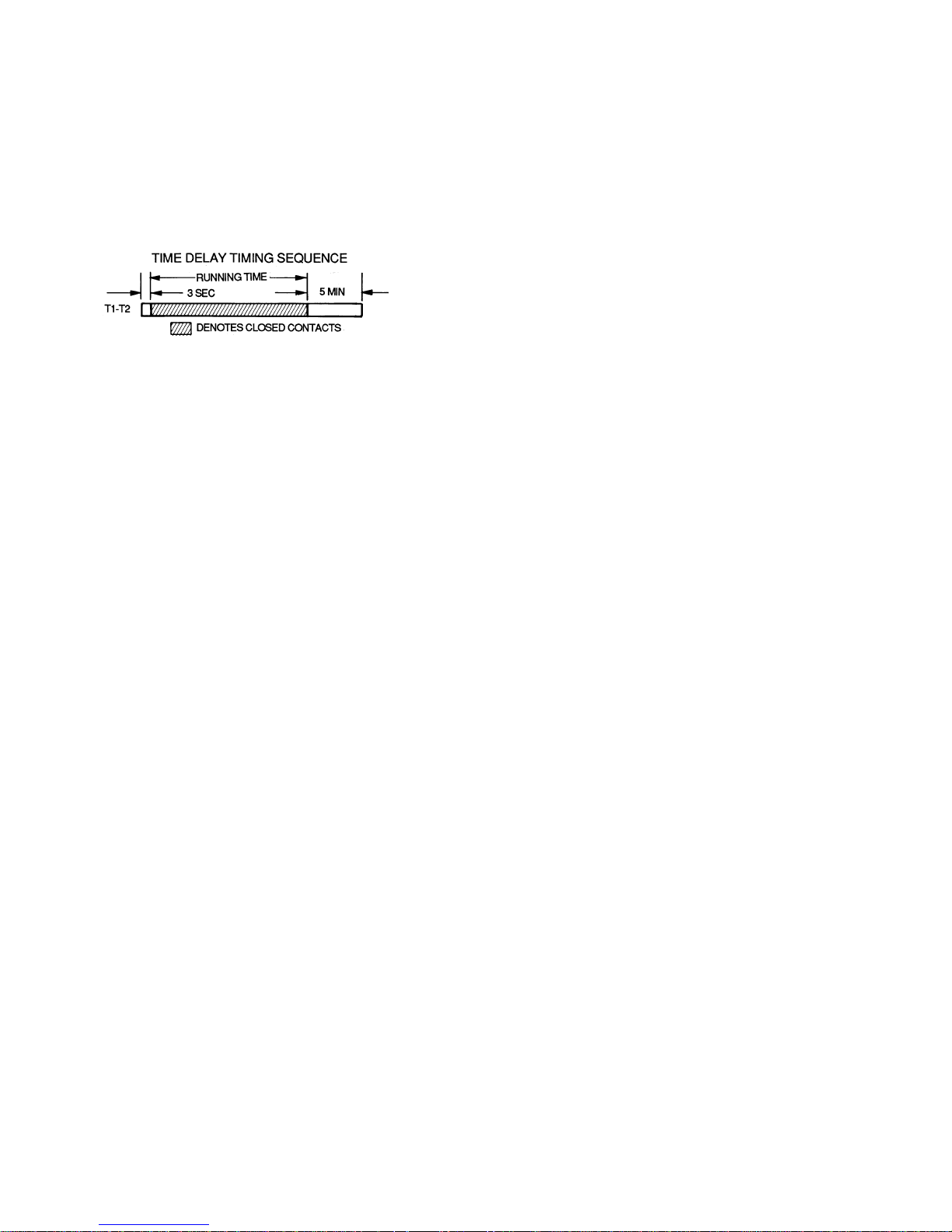
III. TIME GUARD II CIRCUIT (566D ONLY)
Circuit prevents short-cycling by providing a delay of
approximately 5 minutes before restarting compressor afte r
shutdown from safety device action.
On start-up, the Time Guard II timer causes a delay of
approximately 3 seconds after thermostat closes.
On compressor shutdown, the timer recycles for approximately 5 minutes. During this time, the compressor canno t
restart.
Refer to Fig. 21 and to label diagram on unit.
Fig. 21 — Timer Sequence Chart
IV. CRANKCASE HEATER
The heater prevents refrigerant migration and compressor
oil dilution during shutdown whenever compressor is not
operating. It is wired to cycle with the compressor; the
heater is off when compressor is running, and on when compressor is off.
Both compressor service valves must be closed whenever the
crankcase heater is deenergized for more than 6 hours.
The crankcase heater is opera ble as long as the control circuit is energized.
V. COMPRESSOR PROTECTION
A. Circuit Breaker (566D Only)
Calibrated trip manual reset, ambient compensated, magnetic breaker protects against motor overload and locked
rotor conditions.
B. Compressor Overtemperature Protection (IP)
A thermostat installed on compressor motor winding reacts
to excessively high winding temperatures and shuts off the
compressor.
C. Time Guard II Control (566D Only)
Control prevents com pres sor from sh ort cyclin g. See Ope rating Sequence.
D. Crankcase Heater
Heater minimizes absorption of liquid refrigerant by oil in
crankcase during brief or extended shutdown periods. The
control circuit is maintaine d if compresso r fan motor circuit
breakers are turned off. The main disconnect must be on to
energize crankcas e heater.
IMPORTANT: Never open any switch or disconnect that energizes the crankcas e he at er un l ess u ni t is bei n g servi ce d or is
to be shut down for a prolonged period. After a prolonged
shutdown on a service job, energize the crankcase heater for
24 hours before starting the compressor.
E. Advanced Scroll Temperature Protection (ASTP)
See Advanced Scroll Temperature Protection (ASTP) on
page 16.
VI. LOW-PRESSURE SWITCHES
The 569D, 569F, 566E, 576C low-pressure switches are
mounted on the suction line. The 566D low-pressure
switches are mounted on the compressor. Switches are all
fixed, non-adjustable type.
VII. HIGH-PRESSURE SWITCHES
The 569D, 576C and 569F high-pressure switches are
mounted on the liquid line. The 566E150-240 high-pressure
switches are mounted on the discharge line. The 566D
high-pressure switches are mounte d on the compressor. The
switches are all fixed, non-adjustable type.
A. To Check
Slowly close liquid shutoff valve and allow compressor to
pump down. Do not allow compressor pumpdown below
2 psig. Compressor shou ld shut down when suction pressu re
drops to cuto ut pr e ssu re in Tables 1A-1 C, and sh oul d res ta r t
when pressure builds up to cut-in pressure shown.
VIII. DISCHARGE GAS THERMOSTAT (569D090 ONLY)
A sensor on the discha rge li ne will stop the comp ress or if an
abnormally high discharge temperature is detected. If the
unit shuts down on a high discharge temperature fault,
restart the unit by cycling the thermostat or the power
disconnect switch.
IX. OUTDOOR FANS
Each fan is suppor ted by a formed -wire mount bolted to the
fan deck and covered with a wire guard. Fan motors have permanently lubr icate d beari ngs .
NOTE: On 566D units, the exposed end of the motor shaft is
covered with a rubber boot. In case a fan motor must be
repaired or rep laced, be su re the rubbe r boot is put ba ck on
when the fa n is reinstall ed and be sur e the fan gu ard is in
place before starting the unit. Figure 22 shows the proper
position of the mounted fan.
X. LUBRICATION
Fan motors have sealed bea r ings. No provisions ar e made for
lubrication.
Compressor has its own oil supply. Loss of oil due to a leak in
the system should be th e only re ason for a dding o il afte r the
system has been in operation .
XI. COIL CLEANING AND MAINTENANCE
This section discusses the cleaning and the maintenance of
standard coils and E-Coated coils. Routine cleaning of coil
surfaces is e ss ent i al t o mi nim ize c o ntamination build-up and
remove harmful residue. Insp ect coils monthly and clea n as
required.
A. Cleaning Standard Coils
Standard coils can be cleaned with a vacuum cleaner,
washed out with low velocity water, blown out with low-pressure compressed air, or brushed (do not use wire brush). Fan
motors are drip-proof but not waterproof. Do NOT use acid
cleaners.
Clean outdoor coil annually or as required by location or outdoor air conditions. Inspect coil monthly, and clean as
required. Fins are not continuous through coil sections; dirt
and debris may pass through first section, become trapped
between second and third rows of fins and restrict outdoor
airflow. Use a flashlight to determine if dirt or debris has
collected between coil sections. Clean coil as follo ws:
1. Turn off unit power.
2. Remove screws holding rear corner posts and top
cover in place. Pivot top cover up 12 to 18 in. and
support with a rigid support. See Fig. 23.
3. Remove clips securing tube sheets together at the
return bend end of the coil. Carefully sprea d the ends
of the coil rows apart by moving the outer sections.
See Fig. 24.
—22—
Page 23
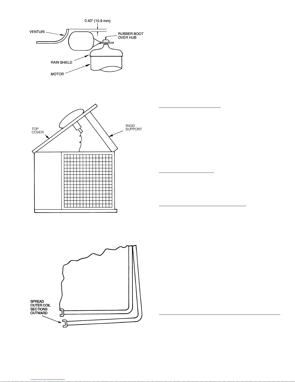
Fig. 22 — Outdoor Fan — 566D Units
Fig. 23 — Pivot and Support Top Cover
Fig. 24 — Coil Cleaning (Typical)
4. Using a water hose, or other suitable equipment,
flush down between the sections of coil to remove dirt
and debris.
5. Clean the remaining surfaces in the normal manner.
6. Reposition outer coil sections.
7. Reinstall cl ips which secure tub e sheets.
8. Replace top cover and rear corner posts.
B. Cleaning and Maintaining E-Coated Coils
Routine cleaning of condenser coil surfaces is essential to
maintain proper operation of the unit. Elimination of contamination and removal of harmful residue will greatly
increase the li fe of the coil and extend the life of the unit.
The following m ainte nan ce and clea ning proc edures a re re commended as part of the routine maintenance a ctivities to
extend the life of the coil.
Remove Surface Loaded Fibers
Debris such as dirt and fibers on the surface of the coil
should be removed with a vacuum cleaner. If a vacuum
cleaner is not available, a soft brush may be used. The cleaning tool should be applied in the direction of the fins. Coil
surfaces can be easily damaged (fin edges bent over) if the
tool is applied across the fins.
NOTE: Use of a water stream, such as a garden hose, against
a surface loaded coil will drive the fibers and dirt into the
coil. This will make cleaning efforts more difficult. Surface
debris must be completely removed prior to using a low
velocity clean water rinse.
Periodic Clean Water Rinse
A periodic clean water rinse is very beneficial for coils that
are applied in coastal or industrial environments. However,
it is very important that the water rinse is made with very
low velocity water stream to avoid damaging the fin edges.
Monthly cleaning is recommended.
Routine Cleaning of E-Coated Coil Surfaces
Monthly cleaning with Environmentally Sound Coil Cleaner
is essential to extend the life of coils. It is recommended that
all coils including standard aluminum, pre-coated, copper/
copper, or E-coated coils be cleaned with the Environmentally Sound Coil Cleaner as described below. Coil cleaning
should be part of the regularly scheduled maintenance procedures of the unit to ensure long life of the coil. Failure to
clean the coils may result in reduced durability in the
environment.
Environmentally Sound Coil Cleaner is non-bacterial,
biodegradable and will not harm the coil or surrounding
components such as electrical wiring, painted metal surfaces
or insulation. Use of non-recommended coil cleaners is
strongly discouraged since coil and unit durability could be
affected.
The following field-supplied equipment is required for coil
cleaning:
1
•2
/2 gallon garden sprayer
• water rinse with low velocity spray nozzle
Environmentally Sound Coil Cleaner Ap plication Inst ructions
Perform the following procedure to clean the coil.
NOTE: Wear proper eye protection such as safety glasses
during mixing and application.
1. Remove all surface debris and dirt from the coil with
a vacuum cleaner.
2. Thoroughly wet finned surfaced with clean water and
a low velocity garden hose, being careful not to bend
fins.
—23—
Page 24
3. Mix Environmentally Sound Coil Cleaner in a 21/2 gallon garden sprayer according to the instructions
included with the Cleaner. The optimum solution temperature is 100 F.
CAUTION: DO NOT USE water in excess of 130 F.
Enzymes in coil cleaner will be destroyed and coil
cleaner will not be effective.
4. Thoroughly apply Environmentally Sound Coil
Cleaner solution to all coil surfaces including finned
area, tube sheets, and coil headers. Hold garden
sprayer noz zle clos e to fin ned ar eas and appl y cl eaner
with a vertical, up-and-down motion. Avoid spraying
in horizontal pattern to minimize potential for fin
damage. Ensure cleaner thoroughly penetra tes deep
into finned areas. Interior and exterior finned are as
must be thoroughly cleaned.
5. Allow finned surfaces to remain wet with cleaning
solution for 10 minutes. Ensure surfaces are not
allowed to dry before rinsing. Reapply cleaner as
needed to ensure 10-minute saturation is achieved.
6. Thoroughly rinse all surfaces with low velocity clean
water us in g do wn wa rd r in si ng m ot io n of wa te r sp r ay
nozzle. Protect fins from damage from the spray
nozzle.
CAUTION: Do not use bleach, harsh chemicals, or
acid cleaners on outdoor or indoor coils of any kind.
These types of cleaner s are difficult to rinse, and they
promote rapid corrosion of the fin collar-copper tube
connection. Only use the Environmentally Sound Coil
Cleaner.
Never use high pressure air or liquids to clean coils.
High pressures damage coils and increase the airside
pressure drop. To promote unit integrity, follow cleaning and maintenance procedures in this document.
—24—
Page 25
TROUBLESHOOTING
PROBLEM SOLUTION
COMPRESSOR DOES NOT RUN
Contactor Open
1. Power off. 1. Restore power.
2. Fuses blown in field power circuit. 2. After finding cause and correcting, replace with correct size fuse.
3. No control power. 3. Check control circuit breaker; reset if tripped or replace if defective.
4. Thermostat circuit open. 4. Check thermostat setting.
5. Time Guard II device not operating (566D only). 5. Check Time Guard II device.
6. Compressor circuit breaker tripped (566D only). 6. Check for excessive compressor current draw. Reset breaker;
7. Safety device lockout circuit active. 7. Reset lockout circuit at thermostat or circuit breaker.
8. Low-pressure switch open. 8. Check for refrigerant undercharge, obstruction of indoor airflow, or
9. High-pressure switch open. 9. Check for refrigerant overcharge, obstruction of outdoor airflow, air in
10. Compressor overtemperature switch open. 10. Check for open condition. Allow for reset. Replace if defective.
11. Loose electrical connections. 11. Tighten all connections.
12. Compressor stuck. 12. See compressor service literature.
Contactor Closed
1. Compressor leads loose. 1. Check connections.
2. Motor windings open. 2. See compressor service literature.
3. Single phasing. 3. Check for blown fuse. Check for loose connection at compressor
COMPRESSOR STOPS ON HIGH-PRESSURE SWITCH
Outdoor Fan On
1. High-pressure switch faulty. 1. Replace switch.
2. Reversed fan rotation. 2. Confirm rotation, correct if necessary.
3. Airflow restricted. 3. Remove obstruction.
4. Air recirculating. 4. Clear airflow area.
5. Noncondensables in system. 5. Recover refrigerant and recharge as required.
6. Refrigerant overcharge. 6. Recover refrigerant as required.
7. Line voltage incorrect. 7. Consult power company.
8. Refrigerant system restrictions. 8. Check or replace filter drier, expansion valve, etc. Check that com-
Outdoor Fan Off
1. Fan slips on shaft. 1. Tighten fan hub setscrews.
2. Motor not running. 2. Check power and capacitor.
3. Motor bearings stuck. 3. Replace bearings.
4. Motor overload open. 4. Check overload rating. Check for fan blade obstruction.
5. Motor burned out. 5. Replace motor.
COMPRESSOR CYCLES ON LOW-PRESSURE SWITCH
Indoor-Air Fan Running
1. Compressor suction service valve partially closed. 1. Open valve fully.
2. Liquid line solenoid valve(s) fails to open. 2. Check liquid line solenoid valve(s) for proper operation. Replace if
3. Filter drier plugged. 3. Replace filter drier.
4. Expansion valve power head defective. 4. Replace power head.
5. Low refrigerant charge. 5. Add charge. Check low-pressure switch setting.
replace if defective.
whether compressor suction shutoff valve is fully open. Make sure
liquid line solenoid valve(s) is open.
system, or whether compressor discharge valve is fully open. Be
sure outdoor fans are operating correctly.
terminal.
pressor discharge service valve is fully open.
necessary.
—25—
Page 26
TROUBLESHOOTING (cont)
PROBLEM SOLUTION
COMPRESSOR CYCLES ON LOW-PRESSURE SWITCH (cont)
Airflow Restricted
1. Coil iced up. 1. Check refrigerant charge.
2. Coil dirty. 2. Clean coil fins.
3. Air filters dirty. 3. Clean or replace filters.
4. Dampers closed. 4. Check damper operation and position.
Indoor-Air Fan Stopped
1. Electrical connections loose. 1. Tighten all connections.
2. Fan relay defective. 2. Replace relay.
3. Motor overload open. 3. Power supply.
4. Motor defective. 4. Replace motor.
5. Fan belt broken or slipping. 5. Replace or tighten belt.
COMPRESSOR RUNNING BUT COOLING INSUFFICIENT
Suction Pressure Low
1. Refrigerant charge low. 1. Add refrigerant.
2. Head pressure low. 2. Check refrigerant charge. Check outdoor-air fan thermostat settings.
3. Air filters dirty. 3. Clean or replace filters.
4. Expansion valve power head defective. 4. Replace power head.
5. Indoor coil partially iced. 5. Check low-pressure setting.
6. Indoor airflow restricted. 6. Remove obstruction.
Suction Pressure High
1. Unloaders not functioning. 1. Check unloader adjustments. Check unloader setting.
2. Compressor valve defective. 2. See compressor service literature.
3. Heat load excessive. 3. Check for open doors or windows in vicinity of fan coil.
UNIT OPERATES TOO LONG OR CONTINUOUSLY
1. Low refrigerant charge. 1. Add refrigerant.
2. Control contacts fused. 2. Replace control.
3. Air in system. 3. Purge and evacuate system.
4. Partially plugged expansion valve or filter drier. 4. Clean or replace.
SYSTEM IS NOISY
1. Piping vibration. 1. Support piping as required.
2. Compressor noisy. 2. Check valve plates for valve noise. Replace compressor if bearings
COMPRESSOR LOSES OIL
1. Leak in system. 1. Repair leak.
2. Crankcase heaters not energized during shutdown. 2. Check wiring and relays. Check heater and replace if defective.
3. Improper interconnecting piping design. 3. Check piping for oil return. Replace if necessary.
FROSTED SUCTION LINE
Expansion valve admitting excess refrigerant. Adjust expansion valve.
HOT LIQUID LINE
1. Shortage of refrigerant due to leak. 1. Repair leak and recharge.
2. Expansion valve opens too wide. 2. Adjust expansion valve.
FROSTED LIQUID LINE
1. Restricted filter drier. 1. Remove restriction or replace.
2. Liquid line solenoid valve partially closed. 2. Replace valve.
COMPRESSOR WILL NOT UNLOAD
1. Defective unloader. 1. Replace unloader.
2. Defective capacity control solenoid valve (if used). 2. Replace valve.
3. Miswired capacity control liquid line solenoid (if used). 3. Rewire correctly.
4. Weak, broken, or wrong valve body spring. 4. Replace spring.
COMPRESSOR WILL NOT LOAD
1. Miswired capacity control liquid line solenoid (if used). 1. Rewire correctly.
2. Defective capacity control solenoid valve (if used). 2. Replace valve.
3. Plugged strainer (high side). 3. Clean or replace strainer.
4. Stuck or damaged unloader piston or piston ring(s). 4. Clean or replace the necessary parts.
are worn.
Copyright 2004 Bryant Heating & Cooling Systems Printed in U.S.A. CATALOG NO. 5356-911
Page 27
START-UP CHECKLIST
I. PRELIMINARY INFORMATION
OUTDOOR: MODEL NO. SERIAL NO.
INDOOR: AIR HANDLER MANUFACTURER
MODEL NO. SERIAL NO.
ADDITIONAL ACCESSORIES
II. PRE-START-UP
OUTDOOR UNIT
IS THERE ANY SHIPPING DAMAGE?
IF SO, WHERE:
WILL THIS DAMAGE PREVENT UNIT START-UP? (Y/N)
CHECKPOWER SUPPLY. DOES IT AGREE WITH UNIT? (Y/N)
HAS THE GROUND WIRE BEEN CONNECTED? (Y/N)
HAS THE CIRCUIT PROTECTION BEEN SIZED AND INSTALLED PROPERLY? (Y/N)
ARE THE POWER WIRES TO THE UNIT SIZED AND INSTALLED PROPERLY? (Y/N)
HAVECOMPRESSOR HOLDDOWN BOLTS BEEN LOOSENED (Snubber washers are snug, but not tight)?
(Y/N)
CONTROLS
ARE THERMOSTAT AND INDOOR FAN CONTROL WIRING CONNECTIONS MADE AND CHECKED?
(Y/N)
ARE ALL WIRING TERMINALS (including main power supply) TIGHT? (Y/N)
HAS CRANKCASE HEATER BEEN ENERGIZED FOR 24 HOURS? (Y/N)
(Y/N)
INDOOR UNIT
HAS WATER BEEN PLACEDINDRAINPAN TO CONFIRM PROPER DRAINAGE? (Y/N)
ARE PROPER AIR FILTERS IN PLACE? (Y/N)
HAVE FAN AND MOTOR PULLEYS BEEN CHECKED FOR PROPER ALIGNMENT? (Y/N)
DO THE FAN BELTS HAVE PROPER TENSION? (Y/N)
HAS CORRECT FAN ROTATION BEEN CONFIRMED? (Y/N)
PIPING
ARE LIQUID LINE SOLENOID VALVES LOCATED AT THE INDOOR COILS AS REQUIRED? (Y/N)
HAVELEAK CHECKS BEEN MADE AT COMPRESSOR, OUTDOOR AND INDOOR COILS,
TXVs (Thermostatic Expansion Valves), SOLENOID VALVES, FILTER DRIERS, AND FUSIBLE PLUGS
WITH A LEAK DETECTOR? (Y/N)
LOCATE, REPAIR, AND REPORT ANY LEAKS.
HAVEALLCOMPRESSOR SERVICE VALVES BEEN FULLY OPENED (BACKSEATED)? (Y/N)
HAVELIQUID LINE SERVICE VALVES BEEN OPENED? (Y/N)
IS THE OIL LEVEL IN EACH COMPRESSOR CRANKCASE VISIBLE IN THE COMPRESSOR SIGHT GLASSES
(576C/566D Units Only)? (Y/N)
CHECK VOLTAGE IMBALANCE
LINE-TO-LINE VOLTS: AB
(AB + AC + BC)/3 = AVERAGE VOLTAGE =
MAXIMUM DEVIATION FROM AVERAGE VOLTAGE =
V AC V BC V
V
V
VOLTAGE IMBALANCE = 100 X (MAX DEVIATION)/(AVERAGE VOLTAGE) =
IF OVER 2% VOLTAGE IMBALANCE, DO NOT ATTEMPTTOSTARTSYSTEM!
CALL LOCAL POWER COMPANY FOR ASSISTANCE.
CL-1
Page 28
III. START-UP
CHECK INDOOR UNIT FAN SPEED AND RECORD.
CHECK OUTDOOR UNIT FAN SPEED AND RECORD.
AFTER AT LEAST 10 MINUTES RUNNING TIME, RECORD THE FOLLOWING MEASUREMENTS:
OIL PRESSURE
SUCTION PRESSURE
SUCTION LINE TEMP
DISCHARGE PRESSURE
DISCHARGE LINE TEMP
ENTERING OUTDOOR UNIT AIR TEMP
LEAVING OUTDOOR UNIT AIR TEMP
INDOOR UNIT ENTERING-AIR DB (dry bulb) TEMP
INDOOR UNIT ENTERING-AIR WB (wet bulb) TEMP
INDOOR UNIT LEAVING-AIR DB TEMP
INDOOR UNIT LEAVING-AIR WBTEMP
COMPRESSOR AMPS (L1/L2/L3) / /
CHECK COMPRESSOR ROTATION (Scroll compressors only); IS COMPRESSOR ROTATING
IN PROPER DIRECTION? (Y/N)
CHECK THE COMPRESSOR OIL LEVEL SIGHT GLASSES; ARE THE SIGHT GLASSES SHOWING
OIL LEVEL IN VIEW (576C/566D Units Only)? (Y/N)
CUT ALONG DOTTED LINE
NOTES:
CUT ALONG DOTTED LINE
Copyright 2004 Bryant Heating & Cooling Systems Printed in U.S.A. CL-2 CATALOG NO. 5356-911
 Loading...