

Page 1
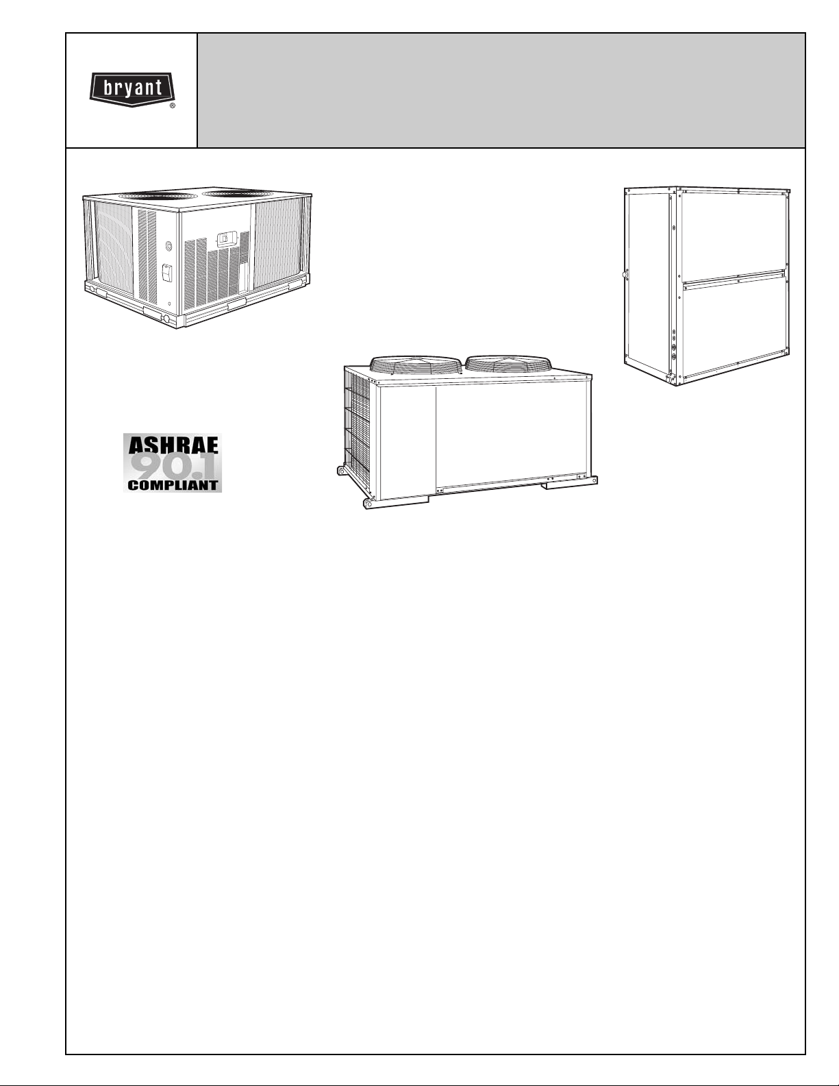
COMMERCIAL AIR-COOLED
CONDENSING UNITS WITH
524A AIR-HANDLING UNITS
569D072-120
576C120
569F120
Models 566D, 566E, 569D,
569F, 576C
with 524A
6to20Tons
524A072-300
FEATURES/BENEFITS
These dependable split systems match Bryant’s indoor-air handlers and direct-expansion coils with outdoor condensing units
for a wide selection of commercial cooling solutions.
CONSTRUCTED FOR LONG LIFE — The569D(singlecircuit, scroll compressor), 576C (single circuit semi-hermetic
compressor), 569F/566E (dual circuit, scroll compressor) and
566D (semi-hermetic compressor) models are designed and
built to last. The copper tube-aluminum fin outdoor coil
construction provides years of trouble-free operation. Where
conditions require them, E-coated coils and pre-coated fin coils
are also available. Cabinets are constructed of prepainted
galvanized steel, delivering unparalleled protection from the
environment. Inside and outside surfaces are protected to
ensure long life, good looks, and reliable operation. Safety controls are used for enhanced system protection and reliability.
EFFICIENT OPERATION — Building owners will appreciate
the high unit EERs (Energy Efficiency Ratios) offered by these
condensing units. These units provide greater efficiency than
similar units in the marketplace, which translates into yearround operating savings.
CONTROLS FOR PERFORMANCE DEPENDABILITY — The
condensing units offer the building owner operating controls
and components designed for performance dependability. The
highly efficient hermetic and semi-hermetic compressors are
engineered for long life and durability. The compressors
include overload protection and vibration isolation for enhancement of quiet operation. The high-pressure switch protects the
entire refrigeration system from abnormally high operating
566D150-240
566E150-240
pressures. A low-pressure switch protects the system from
low-pressure conditions, including loss of charge.
The 569F120 and 566E150-240 units feature 2 scroll compressors and 2 refrigerant circuits that provide continuous air
conditioning and design flexibility. These units also include
Cycle-LOC™ anti-short-cycling protection which helps to
protect the units against compressor failure.
All units include a crankcase heater to eliminate liquid slugging
at start-up. Units with semi-hermetic compressors are also
equipped with an oil-level sight glass.
Latest safety standards are assured through UL and UL
Canada approvals.
INNOVATIVE BRYANT PACKAGED AIR HANDLERS ARE
CUSTOM MATCHED TO THE CONDENSING UNITS — The
524A Series has excellent fan performance, efficient directexpansion (DX) coils, a unique combination of indoor-air quality features, and easy installation. Its versatility and state-ofthe-art features help to ensure that your split system provides
economical performance now and in the future.
Indoor-Air Quality (IAQ) Features — The unique combination
of IAQ features in the 524A Series air handlers help to ensure
that only clean, fresh, conditioned air is delivered to the occupied space.
Direct-expansion (DX) cooling coils prevent the build-up of
humidity in the room, even during part-load conditions. Unit
sizes of 10 tons and above feature dual-circuit coils for
improved temperature control.
Standard 2-in. disposable filters remove dust and airborne particles from the occupied space for cleaner air.
Form No. PDS 569D.72.2
Page 2

Thermal insulation contains an EPA-registered immobilized
anti-microbial agent to inhibit the growth of bacteria and fungi.
The pitched, non-corroding drain pan can be adjusted for a
right- or left-hand connection to suit many applications and
provide positive drainage and to prevent standing condensate.
The 524A accessory economizer can provide ventilation air to
improve indoor air quality by using demand control ventilation.
When used in conjunction with a 2 to 10 VDC adapter on the
actuator and a CO
sensor, the economizer admits fresh
2
outdoor air to replace stale, recirculated indoor air as needed.
Economy — The 524A Series packaged air handlers have low
initial costs, and they continue to save money by providing
reduced installation expense and energy-efficient performance.
Quick installation is ensured by the multipoise design. Units can
be installed in either the horizontal or vertical configuration without modifications. Fan motors and contactors are prewired and
thermostatic expansion valves (TXVs) are factory-installed on
all 524A direct-expansion models.
High efficiency, precision-balanced fans minimize air turbulence, surging, and unbalanced operation, cutting operation
expenses.
The economizer accessory precisely controls the blend of outdoor air and room air to achieve comfort levels. When the
outside air enthalpy is suitable, outside air dampers can fully
open to provide “free” cooling without energizing mechanical
cooling.
Rugged Dependability — The 524A series units are made to
last. The die-formed galvanized steel panels ensure structural
integrity under all operating conditions. Galvanized steel fan
housings are securely mounted to a die-formed galvanized
steel fan deck.
Rugged pillow-block bearings (524A150-300) are securely fastened to the solid steel fan shaft with split collets and clamp
locking devices. Smaller unit sizes have spider-type bearings.
Coil Flexibility — Model 524A direct-expansion coils have galvanized steel casings; inlet and outlet connections are on the
same end. The coils are designed for use with Refrigerant 22
3
and have
/8-in. diameter copper tubes mechanically bonded to
aluminum sine-wave fins. The coils include matched, factoryinstalled thermostatic expansion valves (TXVs) with matching
distributor nozzles.
Easier Installation and Service — Themultipoisedesignand
component layout help you to get the unit installed and running
quickly. Units can be converted from horizontal to vertical operation by simply repositioning the unit. Drain pan connections
are duplicated on both sides of the unit. The filters, motor, drive,
TXVs, and coil connections are all easily accessed by removing
a single side panel.
TABLE OF CONTENTS
Page
Features/Benefits .............................................1,2
ARICapacityRatings ............................................3
OptionsandAccessories .......................................4-6
SelectionProcedure.............................................7
Controls.......................................................8
TypicalWiringSchematics .....................................9,10
569D072-120, 576C120, 569F120
ModelNumberNomenclature.....................................11
PhysicalData .................................................12
Dimensions................................................13,14
PerformanceData...........................................15-25
ElectricalData.................................................26
ApplicationData ...............................................27
TypicalPipingandWiring........................................28
GuideSpecifications.........................................29-32
566D/E150-240
ModelNumberNomenclature.....................................33
PhysicalData ..............................................34,35
Dimensions................................................36-38
PerformanceData...........................................39-52
ElectricalData.................................................53
ApplicationData ............................................54-56
TypicalPipingandWiring.....................................57,58
GuideSpecifications.........................................59,60
524A072-300
ModelNumberNomenclature.....................................61
PhysicalData .................................................62
Dimensions................................................63-65
PerformanceData...........................................66-71
ElectricalData..............................................72-78
ApplicationData ............................................79-81
GuideSpecifications.........................................82,83
2
Page 3
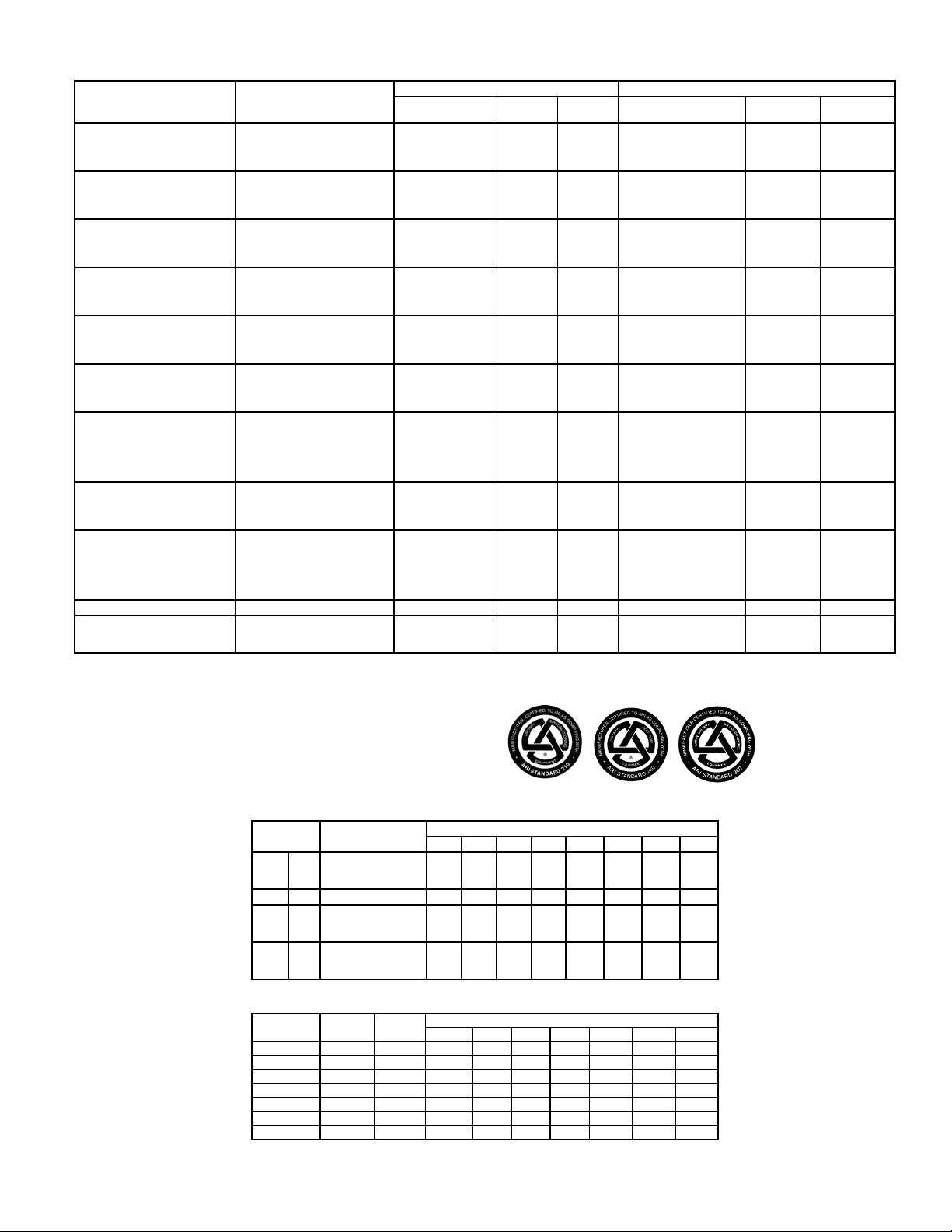
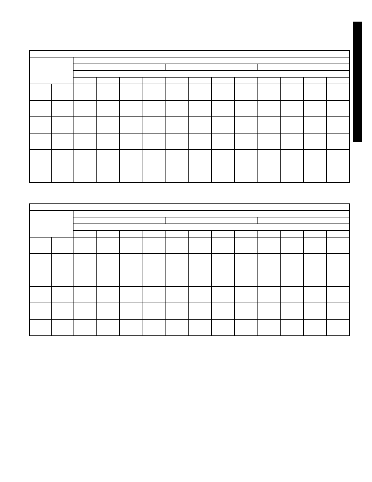
ARI* CAPACITY RATINGS
CONDENSING
UNIT
569D072
569D090
569D120
576C120
569F120
566D150
566E150
566D180
566E180
566D240 524A-C300 244,000 9.5 11.8 248,000 10.5 13.9
566E240
LEGEND
EER — Energy Efficiency Ratio
IPLV — Integrated Part Load Value
N/A — Not Applicable
SST — Saturated Suction Temperature
*Air Conditioning and Refrigeration Institute.
†Ratings in accordance with latest ARI Standard revisions.
**Condensing unit only ratings are at 45 F SST and 95 F entering-air temperature.
NERGY STA R ® compliant combination of condensing unit and air handler/
††E
indoor coil.
AIR
HANDLER/
INDOOR COIL
524A-B072†† 69,000 11.0 N/A
524A-C072†† 72,000 11.2 N/A
524A-B090 71,000 10.8 N/A
524A-C090†† 74,000 11.0 N/A
524A-B072 87,000 10.6 N/A
524A-C072†† 91,000 11.3 N/A
524A-B090 90,000 10.6 N/A
524A-C090†† 94,000 11.2 N/A
524A-B120 118,000 10.3 N/A
524A-C120 125,000 10.4 N/A
524A-B150 123,000 10.4 N/A
524A-C150 130,000 10.4 N/A
524A-B120 114,000 10.3 13.1
524A-C120 119,000 10.3 13.6
524A-B150 118,000 10.4 14.1
524A-C150 125,000 10.3 14.5
524A-B120 113,000 10.3 11.7
524A-C120 118,000 10.5 12.4
524A-B150 118,000 10.5 12.8
524A-C150 124,000 10.9 13.2
524A-B150 138,000 10.4 12.7
524A-C150 144,000 10.6 13.0
524A-B180 144,000 10.6 11.6
524A-C180 146,000 10.8 13.1
524A-B120 135,000 9.7 9.9
524A-C120 143,000 10.2 10.3
524A-B150 145,000 10.5 10.9
524A-C150 153,000 11.1 11.5
524A-B180 152,000 10.8 11.0
524A-C180 161,000 11.3 11.5
524A-B180 176,000 9.8 12.3
524A-C180 182,000 9.7 12.1
524A-B240 184,000 9.8 12.2
524A-C240 196,000 10.0 12.5
524A-B150 176,000 10.0 10.4
524A-C150 185,000 10.3 10.8
524A-B180 187,000 10.2 10.5
524A-C180 198,000 10.6 10.9
524A-B240 194,000 10.1 10.2
524A-C240 204,000 10.4 10.4
524A-C240 243,000 9.6 9.8
524A-B300 242,000 9.6 9.9
524A-C300 252,000 9.7 9.9
Net Cap.
(Btuh)
SYSTEM† CONDENSING UNIT ONLY**
EER IPLV
Gross Cap.
(Btuh)
72,000 12.4 N/A
100,000 12.7 N/A
133,000 12.4 N/A
124,000 12.0 16.5
123,000 12.3 16.0
150,000 12.1 15.8
158,000 12.5 15.1
198,000 11 14.9
204,000 11.9 13.9
259,000 11.2 13.1
EER IPLV
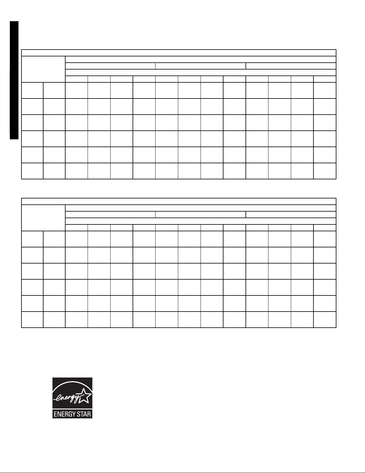
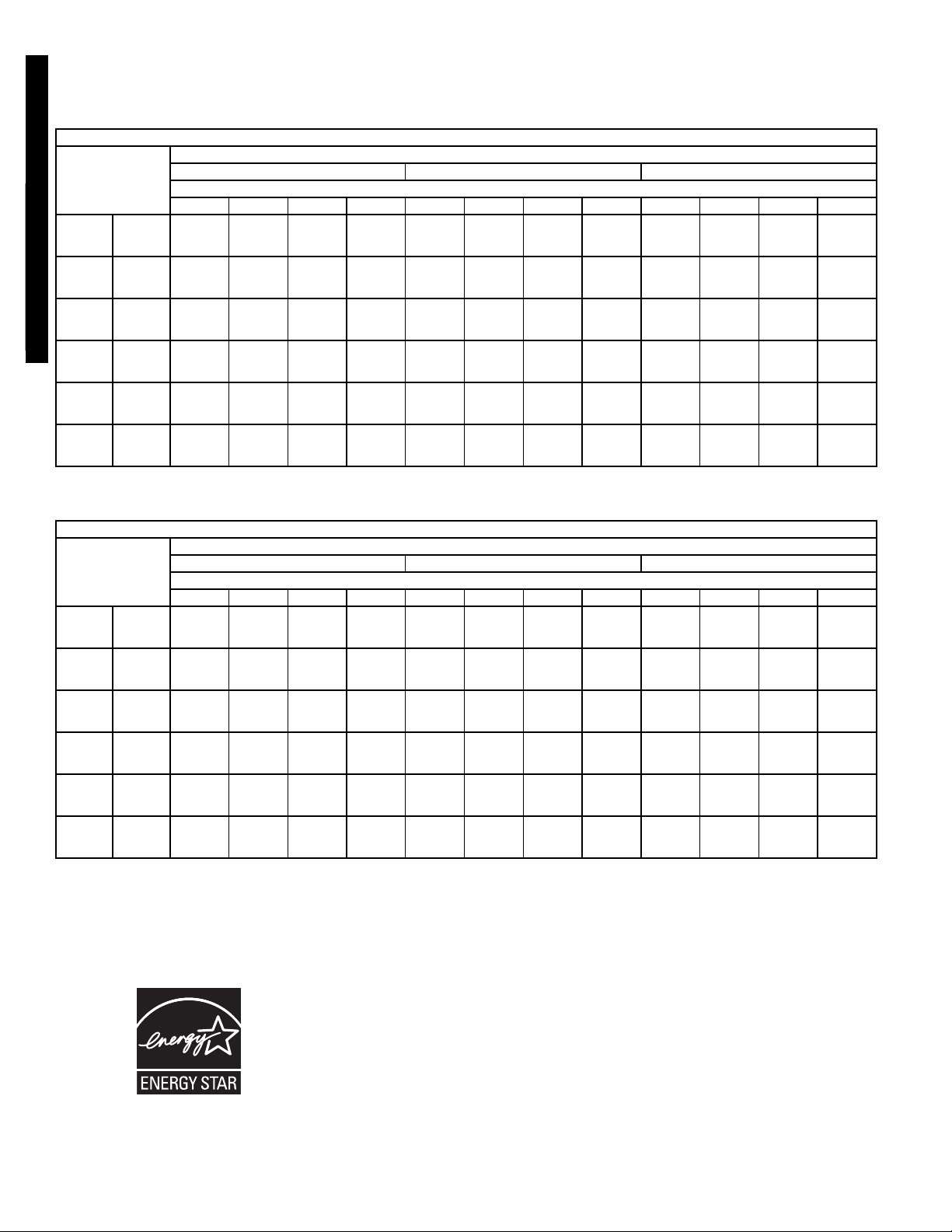
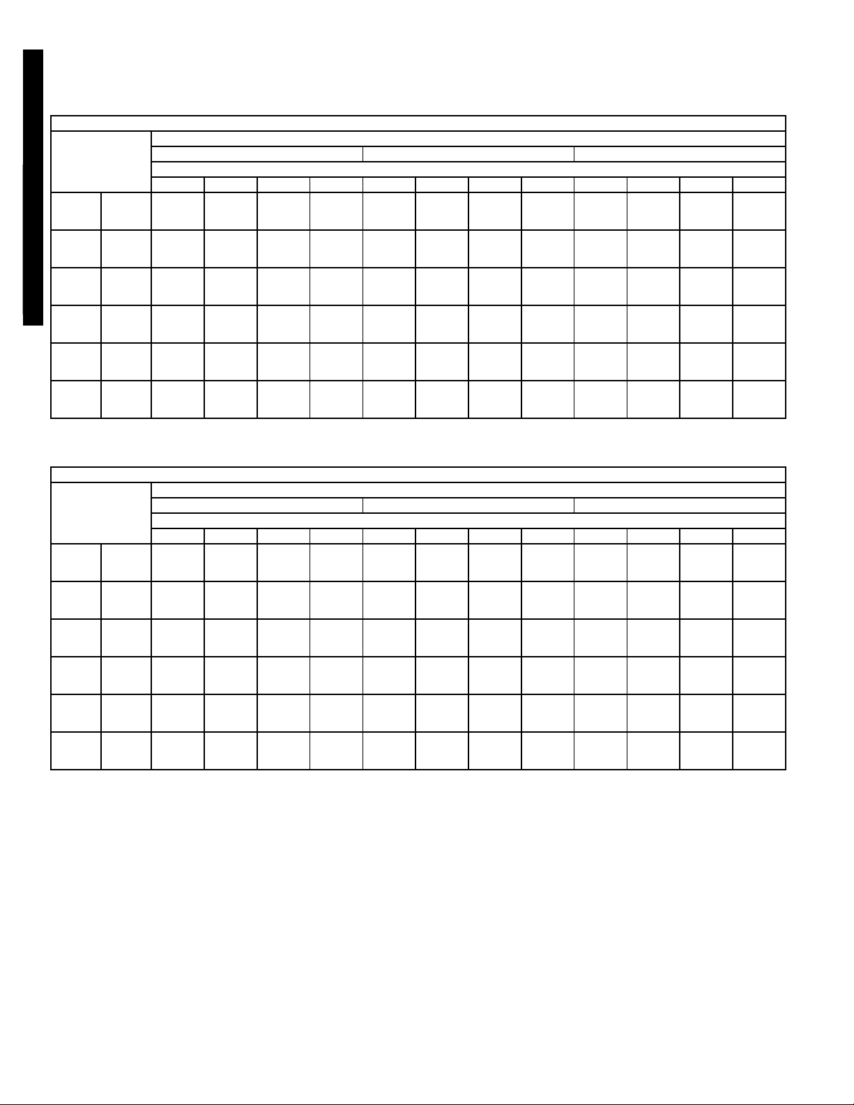
SOUND LEVELS, dB — 569D/576C/566D,E
UNIT
569D
576C 120 83.0 52.5 66.1 75.1 75.4 78.3 73.5 71.0 64.2
566D
566E
SOUND RATING
(60 Hz) dB (A)
072 80.0 43.8 61.4 66.2 70.8 73.8 75.2 73.0 62.7
090 84.0 58.5 67.3 71.3 75.4 77.2 75.8 76.5 71.3
120 85.0 63.7 67.6 72.5 77.0 80.4 77.5 74.7 65.9
150 86.2 — 93.0 86.0 83.0 80.0 78.0 73.0 71.0
180 86.2 — 93.0 86.0 83.0 80.0 78.0 73.0 71.0
240 90.0 83.5 81.5 88.5 86.5 85.5 82.5 76.5 61.5
150 86.9 — 90.9 86.1 83.1 84.0 73.5 71.7 66.7
180 87.5 — 90.9 86.1 83.4 84.5 76.6 73.2 63.5
240 88.0 — 90.9 86.1 83.8 84.5 79.2 74.3 65.5
63 125 250 500 1000 2000 4000 8000
OCTAVE BANDS
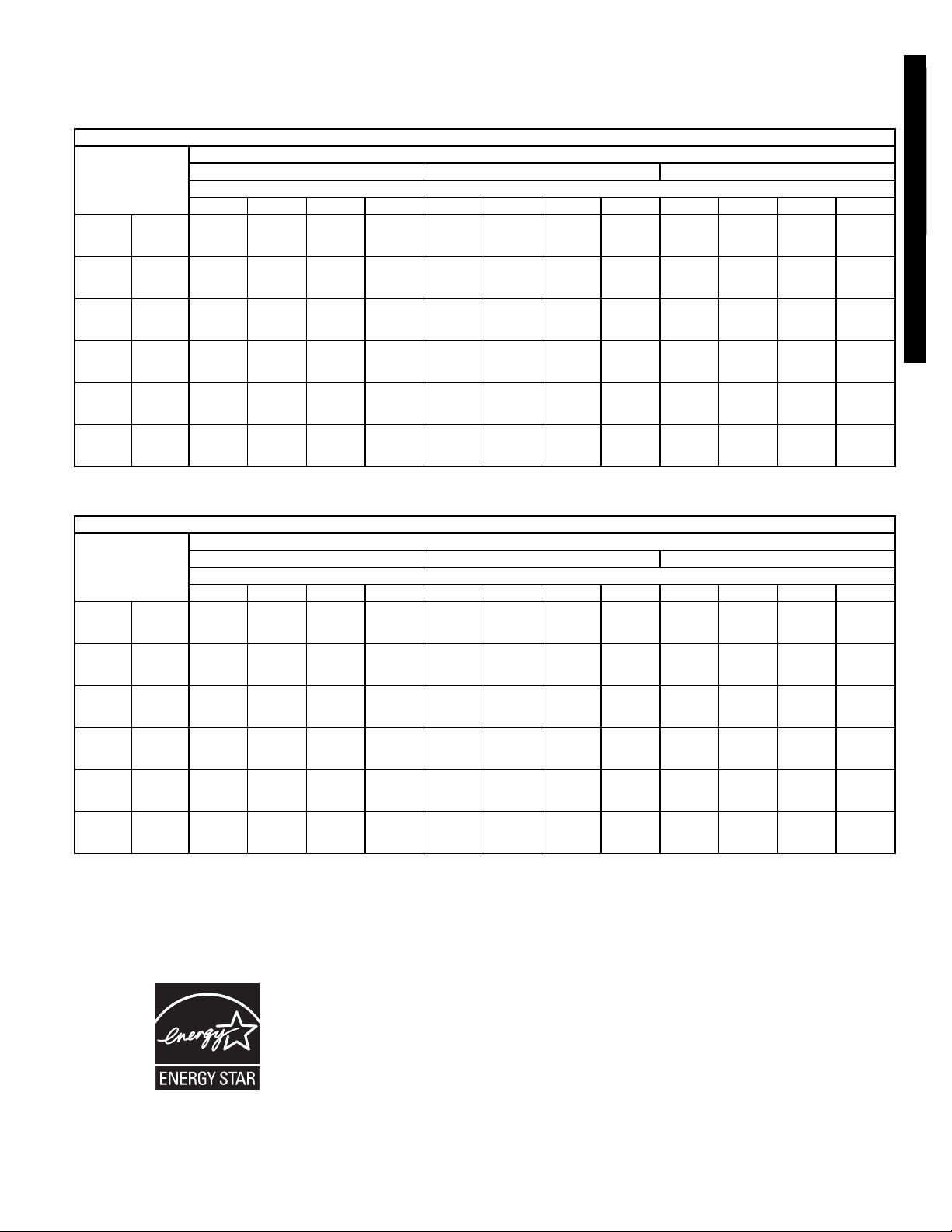
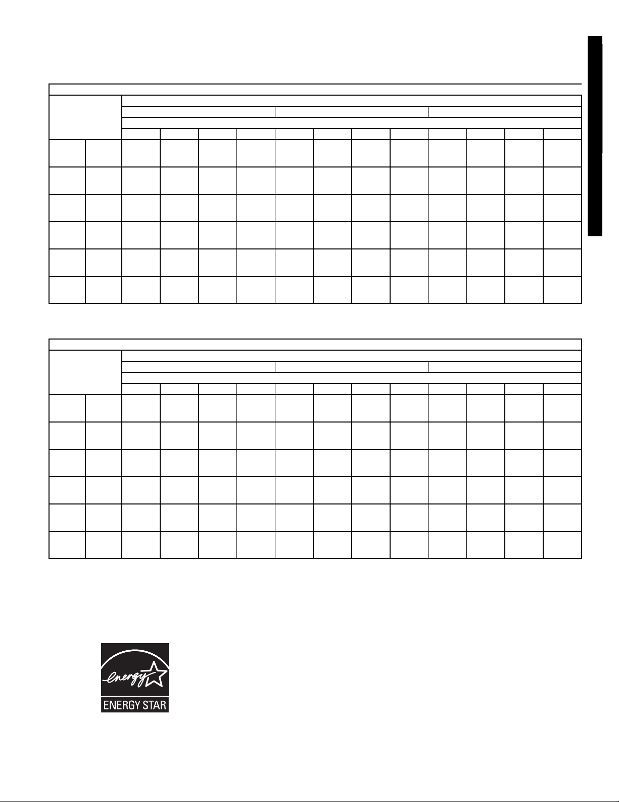
ESTIMATED SOUND POWER LEVELS (Lw) — 524A072-300
UNIT CFM dB(A)
524A072 2,400 86.3 93.2 89.2 85.2 84.2 80.2 78.2 74.2
524A090 3,000 88.3 95.3 91.3 87.3 86.3 82.3 80.3 76.3
524A120 4,000 91.6 98.6 94.6 90.6 89.6 85.6 83.6 79.6
524A150 5,000 91.1 97.3 93.3 89.3 90.3 84.3 82.3 78.3
524A180 6,000 92.7 98.9 94.9 90.9 91.9 85.9 83.9 79.9
524A240 8,000 96.4 102.6 98.6 94.6 95.6 89.6 87.6 83.6
524A300 10,000 96.2 102.5 98.5 94.5 95.5 89.5 87.5 83.5
NOTE: Since this data is calculated, these sound power levels may be different than the actual
sound power levels. The accoustic center of the unit is located at geometric center of the unit.
OCTAVE BAND CENTER FREQUENCY
63 125 250 500 1000 2000 4000
3
Page 4
OPTIONS AND ACCESSORIES
566D, 566E, 569D, 569F, 576C FACTORY-INSTALLED
OPTIONS
Dura-Shield
coil protection to site conditions for optimum durability. See
table below. Consult your Bryant representative for further
information.
E-Coated Aluminum-Fin Coils have a flexible and durable
epoxy coating uniformly applied to all coil surfaces. Unlike brittle
phenolic dip and bake coatings, E-coating provides superior
protection with unmatched flexibility, edge coverage, metal
adhesion, thermal performance, and most importantly, corrosion resistance.
E-coated coils provide this protection since all coil surfaces are
completely encapsulated from environmental contamination.
This coating is especially suitable in industrial environments.
Pre-Coated Fin Coils provide protection in mild coastal
environments.
–20 F Low-Ambient Temperature Kit Option (Motormaster®)
(566E, 569D, 569F, 576C Only) controls outdoor-fan motor
operation to maintain the correct head pressure at low outdoor
ambient temperatures.
115-v Convenience Outlet (566E, 569D, 569F, 576C Only) to
power up electric drills, lights, and refrigerant recovery
machines. This means you are no longer required to run a separate 115-v power supply.
Condenser Coils offer several options to match
Non-Fused Disconnect Switch (566E, 569D, 569F, 576C
Only) to remove power locally at the condensing unit. This
switch also includes a power lockout capability to protect the
service person. This lockout switch saves the service person
time and effort because there is no need to access a distant disconnect switch while servicing the unit.
FIELD-INSTALLED ACCESSORIES
Electric Unloader Package (576C120 Only) includes hard-
ware and solenoid valve to convert a pressure-operated
unloader to electric unloading.
–20 F Low-Ambient Temperature Accessory Kit (Motormaster) controls outdoor-fan motor operation to maintain the correct
head pressure at low outdoor ambient temperatures.
Condenser Coil Grille Package protects condensing unit coil
from impact by large objects and vandalism.
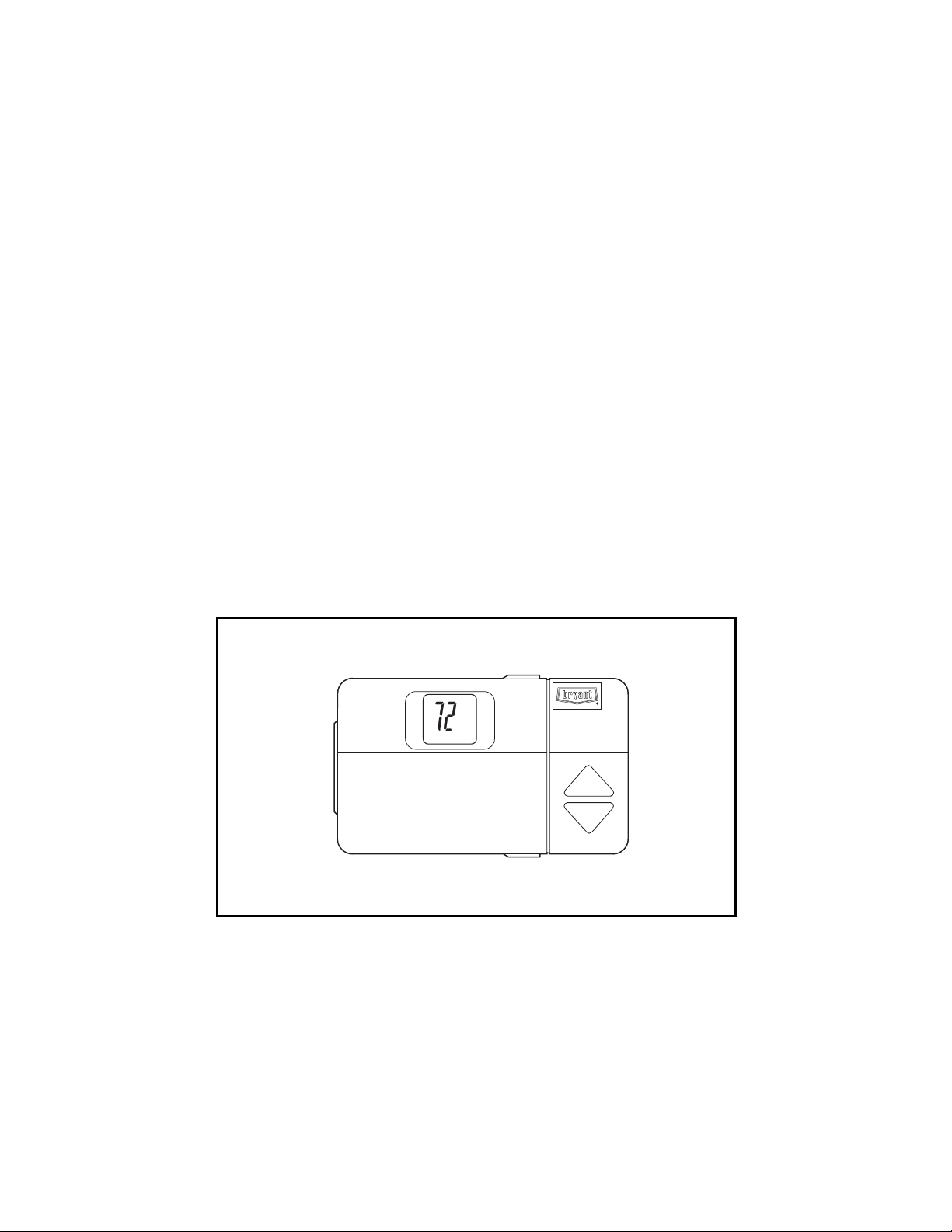
Bryant’s Line of Thermostats provide both programmable and
non-programmable capability with the new Debonair®lineof
commercial programmable thermostats. The Commercial
Electronic thermostats provide 7-day programmable capability
for economical applications.
Hail Guard Package protects against damage from flying
debris and hail.
Gage Panel Package provides a suction and discharge pressure gage for the refrigerant circuit.
Al — Aluminum
FACTORY-INSTALLED
DURA-SHIELD
COIL PROTECTION
CONDENSER COIL OPTIONS
COPPER-TUBE COILS
DURA-SHIELD
WITH
OPTION
Al Fins (Standard Coils) X
Al Fins, E-Coated X
Al Fins, Pre-Coated X
LEGEND
LOW AMBIENT CONTROL
(FACTORY-INSTALLED OR
FIELD-INSTALLED)
Standard
ENVIRONMENT
Mild
Coastal
Industrial/
Coastal
FACTORY-INSTALLED
CONVENIENCE OUTLET
Options and Accessories
4
FACTORY-INSTALLED
DISCONNECT SWITCH
Page 5
OPTIONS AND ACCESSORIES (cont)
524A-B, C FACTORY-INSTALLED OPTIONS
Alternate Fan Motors and Drives are available to provide the
widest possible range of performance.
High-Capacity 4-Row Coils are available to provide increased
latent and sensible capacities (524A-C).
Prepainted Steel Units are available from the factory for appli-
cations that require painted units. Units are painted with AmericanSterlingGraycolor.
FIELD-INSTALLED ACCESSORIES
Two-Row Hot Water Coils have copper tubes mechanically
bonded to aluminum plate fins and non-ferrous headers.
One-Row Steam Coil has copper tubes and aluminum fins.
The Inner Distributing Tube (IDT) design provides uniform
temperatures across the coil face. The steam coil has a broad
operating pressure range; up to 20 psig (138 kPag) at 260 F
(127 C). The IDT steam coils are especially suited to applications where sub-freezing air enters the unit.
Electric Resistance Heat Coils have an open-wire design and
are mounted in a rigid frame. Safety cutouts for high temperature conditions are standard. Terminal block for single-point
power connection is included.
Economizer (Enthalpy Controlled) provides ventilation air
and “free” cooling if outside ambient temperature and humidity
are suitable.
Discharge Plenum directs the air discharge directly into the
occupied space integral horizontal and vertical louvers enable
redirection of airflow. Accessory is available unpainted or
painted. Field assembly required.
Return-Air Grille provides a protective barrier over the returnair opening and gives a finished appearance to units installed in
the occupied space. Accessory is available unpainted or
painted.
Subbase provides a stable, raised platform and room for condensate drain trap connection for vertical floor-mounted units.
Accessory is available unpainted or painted.
Overhead Suspension Package includes necessary brackets
to support units in horizontal ceiling installations.
Bryant’s Line of Thermostats provide both programmable and
non-programmable capability. The Commercial Electronic
thermostats provide 7-day programmable capability for economical applications.
Condensate Drain Trap includes an overflow shutoff switch
that can be wired to turn off the unit if the trap becomes
plugged. Kit also includes a wire harness that can be connected
to an alarm if desired. The transparent trap is designed for easy
service and maintenance.
UV-C Germicidal Lamps kill mold and fungus, which may grow
on evaporator coil and condensate pan surfaces. The use of
UV-C germicidal lamps eliminates the foul odors that result from
this growth of mold and fungus. It also provides a self-cleaning
function for the evaporator coil and drain pan.
Commercial Programmable
and Non-Programmable Thermostat
5
Page 6
DISCHARGE
PLENUM
RETURN-AIR
GRILLE
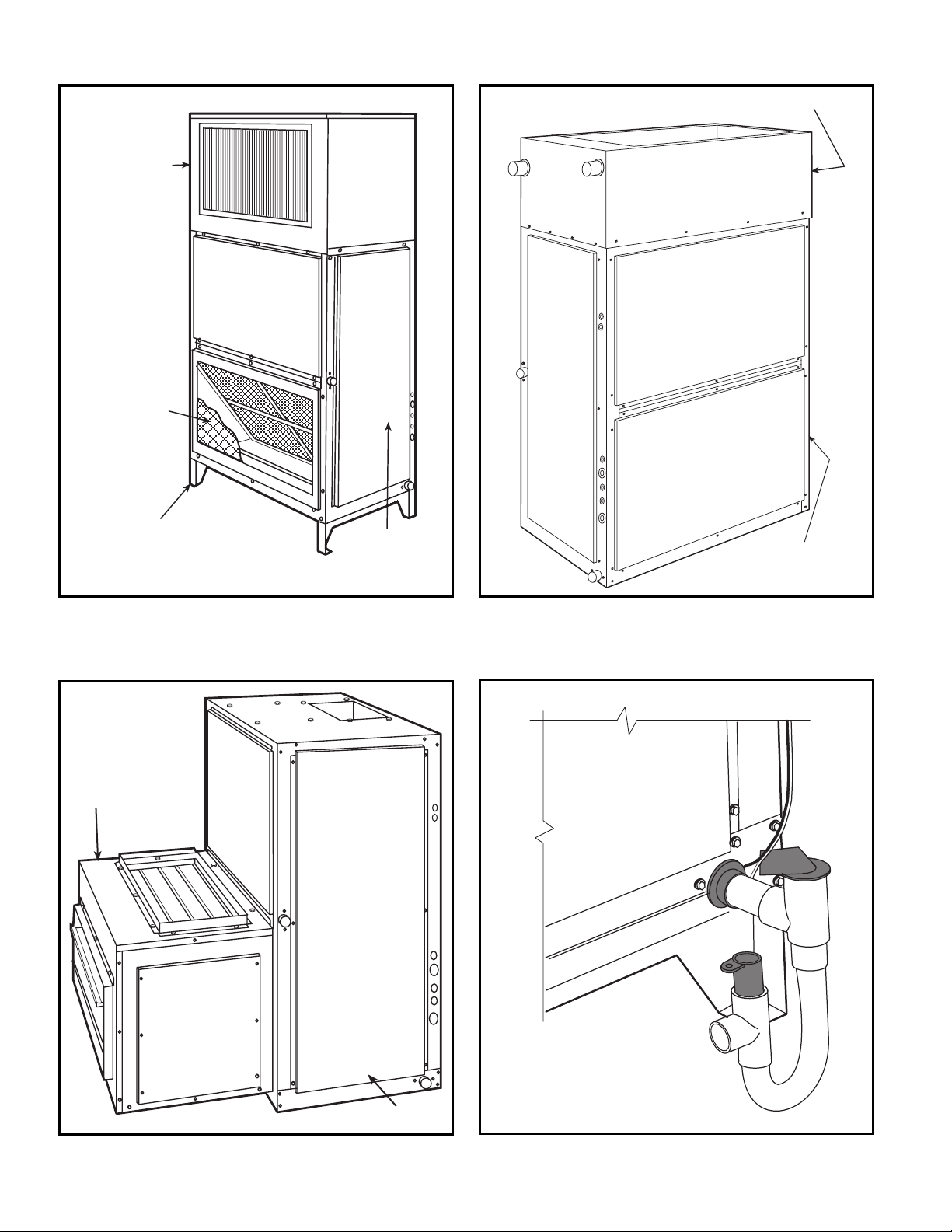
OPTIONS AND ACCESSORIES (cont)
HOT WATER OR
STEAM COIL
SUBBASE
ECONOMIZER
524A with Discharge Plenum,
Return Grille, and Subbase
FAN
COIL
UNIT
FAN COIL
UNIT
524A with Hot Water or Steam Coil
524A with Economizer
FAN COIL UNIT
524A with Condensate Trap
6
Page 7

SELECTION PROCEDURE
To determine combination ratings for 569D/F, 576C and 566D/E
units matched with 524A Series air handlers, follow these steps:
I DETERMINE COOLING LOAD, EVAPORATOR-AIR
TEMPERATURE, AND QUANTITY.
Given:
Total Cooling Capacity
Required(TC)...................... 127,000Btuh
Sensible Heat Capacity
Required(SHC)..................... 95,000Btuh
CompressorType ...........................Scroll
Temperature Air Entering Condenser (Edb). . . . . . . . 95 F
Temperature Air Entering
Evaporator(db/wb)................80Fdb,67Fwb
EvaporatorAirQuantity...................4,000cfm
ExternalStaticPressure .................. 0.4in.wg
Length of Interconnecting
RefrigerantPiping ...................25ft(Linear)
PowerSupply(V-Ph-Hz) ............... 208/230-3-60
II SELECT CONDENSING UNIT AIR-HANDLER
COMBINATION.
For this example, select a 569D120 matched with a
524A-C120 with high-capacity 4-row coil This 569D120/
524A-C120 condensing unit air-handler combination
provides 130,000 Btuh of total cooling capacity and
98,200 Btuh of sensible capacity at the given conditions. If
other temperatures or airflow values are required, interpolate the values from the combination ratings.
III DETERMINE SIZES OF LIQUID AND SUCTION LINES.
Enter Refrigerant Piping Sizes table. The sizes shown are
based on an equivalent length of pipe. This equivalent
length is equal to the linear length of pipe indicated at the
top of each sizing column, plus a 50% allowance for fitting
losses. (For a more accurate determination of actual
equivalent length in place of using the estimated 50%
value, refer to a standard refrigeration piping practice.) For
this example, note in the linear length column that the
1
proper pipe size is
/2in. for the liquid line and 13/8in. for
the suction line.
IV DETERMINE FAN RPM AND BHP (BRAKE
HORSEPOWER).
At the Air Handler Fan Performance table enter at 524AC120 with high capacity coil at 4000 cfm and move to the
External Static Pressure (ESP) column. Note that the conditions require 803 rpm at 1.77 bhp.
V DETERMINE MOTOR AND DRIVE.
Enter the Fan Motor Data tables and find the standard
motor for 524A-C120 unit rated at 2.4 Hp. Since the bhp
required is 1.77, a standard motor satisfies the requirement and should be used.
Next, find the type of drive that satisfies the 803 rpm
requirement in the Drive Data tables. For the 524A-C120
unit, the Standard Drive table on shows an rpm range of
666-863. Since the rpm required is 803, the standard drive
satisfies the requirement and should be used. Select the
standard motor and standard drive combination (option
code GC or ED).
7
Page 8

CONTROLS
OPERATING SEQUENCES
569D072-120, 576C120 — At start-up, the thermostat calls for
cooling. With all safety devices satisfied, the compressor
contactor and fan contactor energize, causing the compressor
and outdoor-fan motor to operate. Thermostat contacts
energize, allowing the field-supplied and field-installed indoorfan contactor to function. A field-supplied and field-installed liquid line valve also opens, allowing the system to function in
Cooling mode. As cooling demand is satisfied, the thermostat
contacts break, deenergizing the contactor and causing the
system to shut off. The liquid line solenoid valve closes, minimizing the potential for refrigerant migration. The compressor
does not restart until the thermostat again calls for cooling. The
system is protected with a safety circuit so that the system will
not start if a fault exists (i.e., high or low pressure fault). To reset
the safety circuit, set the thermostat to eliminate the cooling
demand, then return to original set point. This should be done
only once, and if system shuts down due to the same fault,
determine the problem before attempting to restart the system.
566D150-240 — When the first stage of cooling thermostat
closes, the timer starts. After approximately 3 seconds, the
timer activates the compressor and fan motor no. 1 contactors.
When the liquid pressure builds to approximately 257 psig, fan
motor no. 2 is energized.
When there is demand for additional cooling capacity, the
second stage of the cooling thermostat closes, energizing a
field-supplied liquid line solenoid (LLS) valve, which opens. This
increases the suction pressure, causing the compressor to
operate at higher capacity (compressor loads).
When the fan switch is set at AUTO, the indoor-air fan cycles
with the compressor. When the switch is set at CONT, the
indoor-air fan runs continuously.
At shutdown, the Time Guard II timer prevents the compressor
from restarting for approximately 5 minutes.
In addition, an LLS valve wired in parallel with the compressor
contactor coil shuts off the liquid line to prevent refrigerant
migration back to the compressor during the off cycle.
569F120 — When the thermostat calls for stage one cooling at
start-up, and all safety devices are satisfied, the compressor
contactor no. 1 (C1) energizes causing compressor no. 1 and
outdoor-fan motor no. 1 to start (the indoor-fan contactor should
be wired to start at the same time as the compressor). The
liquid line solenoid (LLS) valve will open when compressor no. 1
starts, allowing refrigerant to flow in the system.
When the thermostat calls for stage two cooling, compressor
contactor no. 2 (C2) energizes causing compressor no. 2 and
outdoor-fan motor no. 2 to start. As the cooling demand
decreases, stage two on the thermostat opens, causing
compressor no. 2 and outdoor-fan motor no. 2 to shut down. As
the cooling continues to decrease, stage one of the thermostat
opens causing compressor no. 1 and outdoor-fan motor no. 1 to
shut down. The LLS valve for each compressor will close when
the associated compressor stops, minimizing the potential for
refrigerant migration during the off cycle.
The indoor-fan motor will stop if the thermostat is set to AUTO
and will continue to operate if the thermostat is set to CONT.
TM
Each compressor is protected with a Cycle-LOC
device so
that the compressor will not operate if there is a high-pressure
fault, low pressure fault, or a compressor is off due to internal
line break overcurrent/overtemperature protection. To reset the
Cycle-LOC device, set the thermostat higher to remove the
cooling demand, then return to the original set point. This
should be done only once. If the system shuts down with the
same fault, the cause for the fault should be determined and
corrected before the a Cycle-LOC device is reset again.
566E150-240 — At start-up, when the thermostat calls for first
stage cooling and all safety devices are satisfied, the compressor contactor (C1) energizes causing compressor no. 1 and fan
motor no. 1 to start. Fan motor no. 2 will start when the fan
cycling pressure switch (FCPS) closes as discharge pressure
builds (refer to physical data table for FCPS specifications).
With the indoor-fan contactor wired to TB2-4 and TB2-9
contacts on the terminal block, the indoor fan will also start with
the compressor. The liquid line solenoid (LLS) valve will open
when compressor no. 1 starts, allowing refrigerant to flow in the
system.
When the thermostat calls for stage two cooling, compressor
contactor no. 2 (C2) energizes causing compressor no. 2 to
start. As the cooling demand decreases, stage two on the
thermostat opens, causing compressor no. 2 to shut down. As
the cooling continues to decrease, stage one of the thermostat
opens causing compressor no. 1 and outdoor-fan motor to shut
down. The LLS valve for each compressor will close when the
associated compressor stops, minimizing the potential for
refrigerant migration during the off cycle.
The indoor-fan motor will stop if the thermostat is set to AUTO
and will continue to operate if the thermostat is set on CONT.
Each compressor is controlled by the thermostat so they will not
start until there is a demand from the thermostat. Each
compressor is protected with a Cycle-LOC device so that the
compressor will not operate if there is a high-pressure fault,
low-pressure fault, or compressor is off due to internal line
break overcurrent/overtemperature protection. To reset the a
Cycle-LOC device, set the thermostat higher to remove the
cooling demand, then return to the original set point. This
should be done only once. If the system shuts down with the
same fault, the cause for the fault should be determined and
corrected before the a Cycle-LOC device is reset again.
8
Page 9
NOTES:
1. If any of the original wire furnished must be
replaced, it must be replaced with type 90° C
wire or its equivalent.
2. Thermostat: HH07AT170, 172, 174 & P2722783
Subbase: HH93AZ176, 178 & P272-1882, 1883
or HH93AZ177 & 179.
3. Sealed VA for IFC and LLSV is not to exceed
22.
4. Use copper conductors only.
5. TRAN is wired for 230 v unit. If unit is to be run
with 200 v power supply, disconnect BLK wire
from 230 v tap and connect to 200 v tap.
6. If TRAN is wired for 460-3-60 v and unit is to be
run with 400-3-50 v power supply, disconnect
BLK wire from 460 v tap and connect to 400 v
tap.
7. Three-phase motors are protected under primary single phasing conditions.
VO LTAGE
RATING
24 V
CB MUST
Mfg. Part No.
Potter & Brumfield
W28X-1024-3.2
TRIP
AMPS
3.2
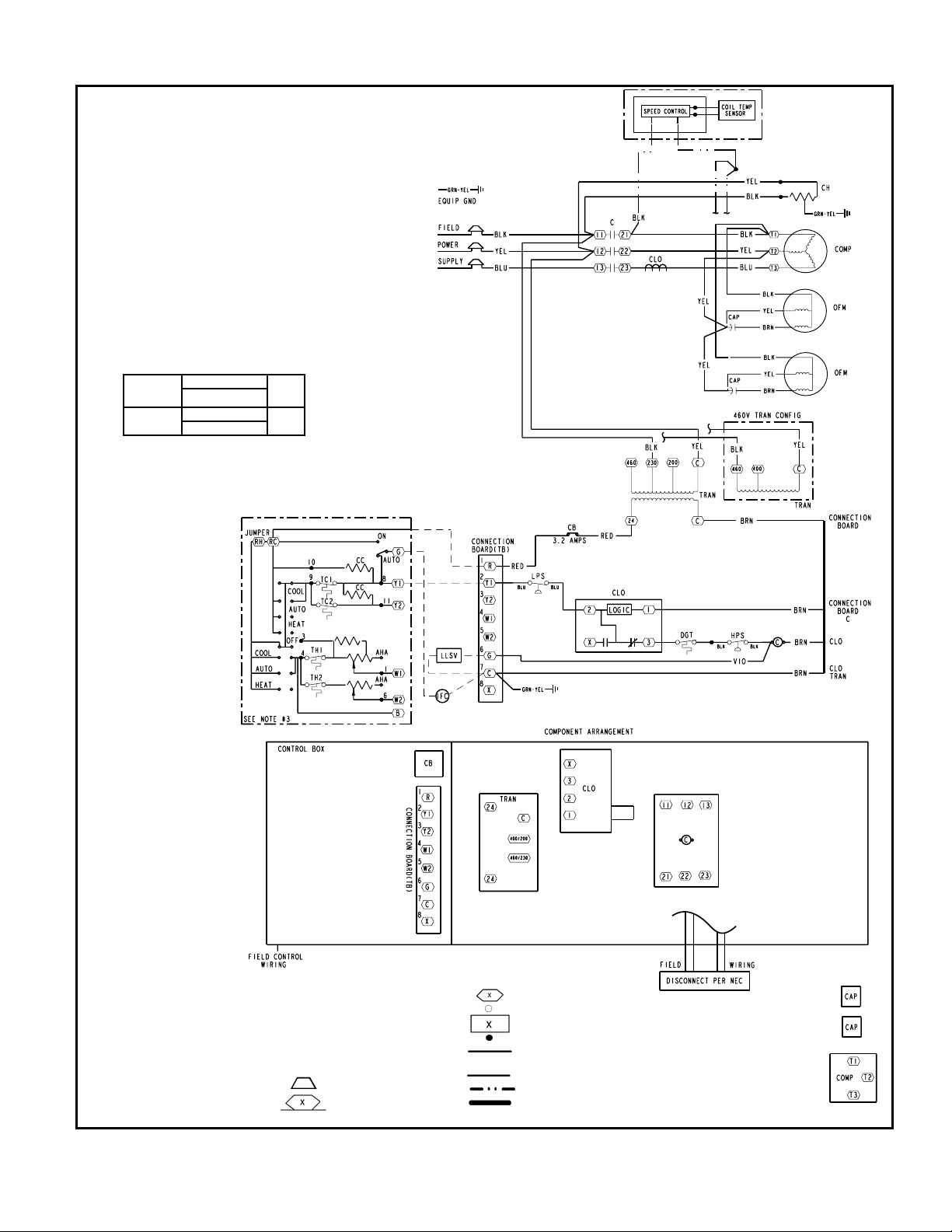
TYPICAL WIRING SCHEMATICS
AHA — Adjustable Heat Anticipator
C—Contactor, Compressor
CAP — Capacitor
CB — Circuit Breaker
CC — Cooling Compensator
CH — Crankcase Heater
CLO — Compressor Lockout
COMP — Compressor Motor
DGT — Dischar ge Gas T hermos tat
EQUIP — Equipment
GND — Ground
HPS — High-Pressure Switch
IFC — Indoor-Fan Contactor
LEGEND
LLSV — Liquid Line Solenoid Valve
LPS — Low-Pressure Switch
NEC — National Electrical Code
OFM — Outdoor-Fan Motor
QT — Quadruple Terminal
TB — Ter minal Block
TC — Thermostat-Cooling
TH — Thermostat-Heating
TRAN — Transformer
Field Splice
Marked Wire
569D090, 208/230-3-360 and 460-3-60 Units
Terminal (Marked)
Terminal (Unmarked)
Terminal Block
Splice
Factory Wiring
—— Field Control Wiring
Field Power Wiring
Accessory or Optional Wiring
To Indicate Common Potential
Only, Not Represent Wiring
9
Page 10
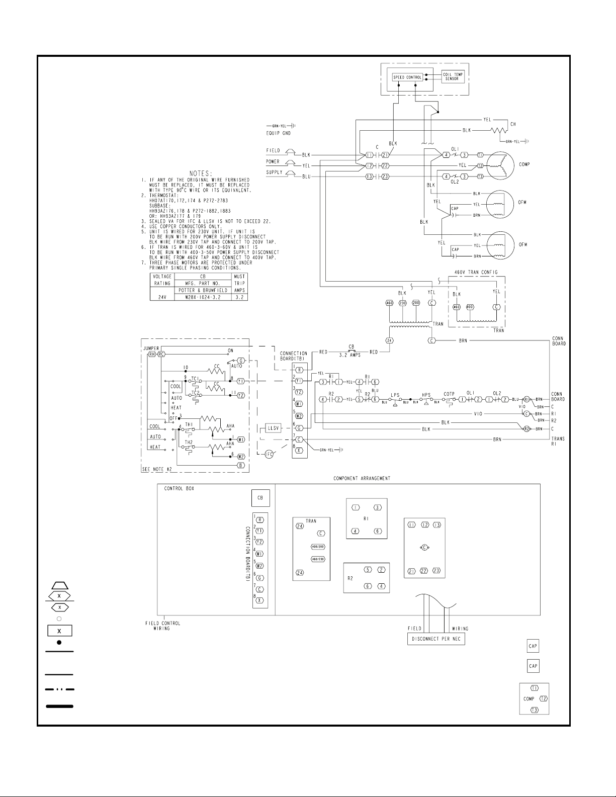
TYPICAL WIRING SCHEMATICS (cont)
AHA — Adjustable Heat
C—Contactor,
CAP — Capacitor
CB — Circuit Breaker
CC — Cooling Compensator
CH — Crankcase Heater
COMP — Compressor Motor
COTP — Compressor Over
EQUIP — Equipment
GND — Ground
HPS — High-Pressure Switch
IFC — Indoor-Fan Contactor
LLSV — Liquid Line Solenoid
LPS — Low-Pressure Switch
NEC — National Electrical Code
OFM — Outdoor-Fan Motor
OL — Overload Relay
R—Relay
TB — Terminal Block
TC — Thermostat-Cooling
TH — Thermostat-Heating
TRAN — Transformer
Anticipator
Compressor
Temperature Protection
Val ve
Field Splice
Marked Wire
Terminal (Marked)
Terminal (Unmarked)
Terminal Block
Splice
Factory Wiring
——
Field Control Wiring
Field Power Wiring
Accessory or
Optional Wiring
To Indicates Common
Potential Only, Not
Represent Wiring
LEGEND
576C120, 208/230-3-60 and 460-3-60 Units
10
Page 11
MODEL NUMBER NOMENCLATURE
569D P X 072 000 ––
569D072-120, 576C120, 569F120 50TFQ004-012
569F — Dual Circuit Commercial Air-Cooled
Voltage Designation
E — 460-3-60
P — 208/230-3-60
T
Heating
X—None
Nominal Tons Cooling
072 — 6 (569D Only)
090 — 7-1/2 (569D Only)
120 — 10 (569D, 569F)
576C — Commercial Air-Cooled Condensing
Voltage Designation
E — 460-3-60
P — 208/230-3-60
T — 575-3-60
Unit With Scroll Compressor
Condensing Unit With Scroll Compressor
— 575-3-60
Unit With Semi-Hermetic Compressor
Factory-Installed Options*569D — Commercial Air-Cooled Condensing
Heating Capacity
000 — No Heat
576C P X 120 000 ––
Factory-Installed Options*
Heating Capacity
000 — No Heat
Heating
X—None
*Contact your local representative for more details.
Nominal Tons Cooling
120—10
Quality Assurance
Certified to ISO 9001:2000
11
Page 12
PHYSICAL DATA
569D072-120, 576C120, 569F120 UNITS
UNIT 569D072 569D090 569D120 576C120 569F120
1
NOMINAL CAPACITY (tons) 67
/
2
10 10 10
OPERATING WEIGHT (lb)
Aluminum Coils (Standard) 300 383 430 575 488
Copper Coils (Optional) 352 484 531 676 589
RREFRIGERANT TYPE*
Operating Charge, Typical (lb)† 12 20 22 24 11/Circuit
Shipping Charge (lb) 2.0 2.0 2.0 2.0 2.0
R-22
COMPRESSOR
Type Scroll Reciprocating Scroll
Qty...Model 1...SR_68 1...SR_94 1...ZR125 1...06DH824 2...SR_60
Oil Charge (oz) 88 90 110 128 72 (ea)
No. Cylinders N/A 6 N/A
Speed (rpm) 3500 1750 3500
CONDENSER FAN
Qty...Rpm 2...850 2...1100 2...1100 2...1100 2...1100
50TFQ004-012
569D072-120, 576C120, 569F120
Motor HP (rpm)
Diameter 22 22 22 22
Nominal Airflow (CfmTotal) 5400 6500 6500 6500
1
/
8
1
/
4
1
/
4
1
/
4
Watts (Total) 340 570 570 570
CONDENSER COIL (Qty) 2 2
Face Area (sqfttotal) 29.2 29.2 29.2
Rows...Fins/in. 1...17 2...17 2...17 2...17 2...17
Storage Capacity (lb)** 17.3 34.2 34.2 34.2 17.1 (ea)
CONTROLS
Pressurestat Settings (psig)
High Cutout 428 ± 10 428 ± 10 428 ± 10
Cut-in 320 ± 20 320 ± 20 320 ± 20
Low Cutout 27 ± 3 27 ± 3 27 ± 3
Cut-in 44 ± 5 44 ± 5 44 ± 5
DISCHARGE GAS THERMOSTAT (°F) 2 2
Cutout — 270 ± 9 — — —
Cut-in — 190 ± 13 — — —
PRESSURE RELIEF
Location Suction Line
Temperature (F) 200
PIPING CONNECTIONS (in. ODM)
Qty...Suction 1...11/
Qty...Liquid
1...
8
3
/
8
*Unit is factory-supplied with holding charge only.
†Typical operating charge with 25 ft of interconnecting piping.
**Storage capacity of condenser coil with coil 80% full of liquid R-22 at
95 F.
1...11/
1...3/
8
8
1...13/
1...1/
8
2
1...13/
1...1/
8
2
NOTE: Unit 576C120 has one step of unloading. Full load is at 100% of
capacity, and one step of unloading is 67% capacity. Unit 576C120 has
the following unloader settings: load is 70 ± 1 psig and unload is 60 ±
2psig.
1
/
2...11/
2...3/
4
8
8
12
Page 13
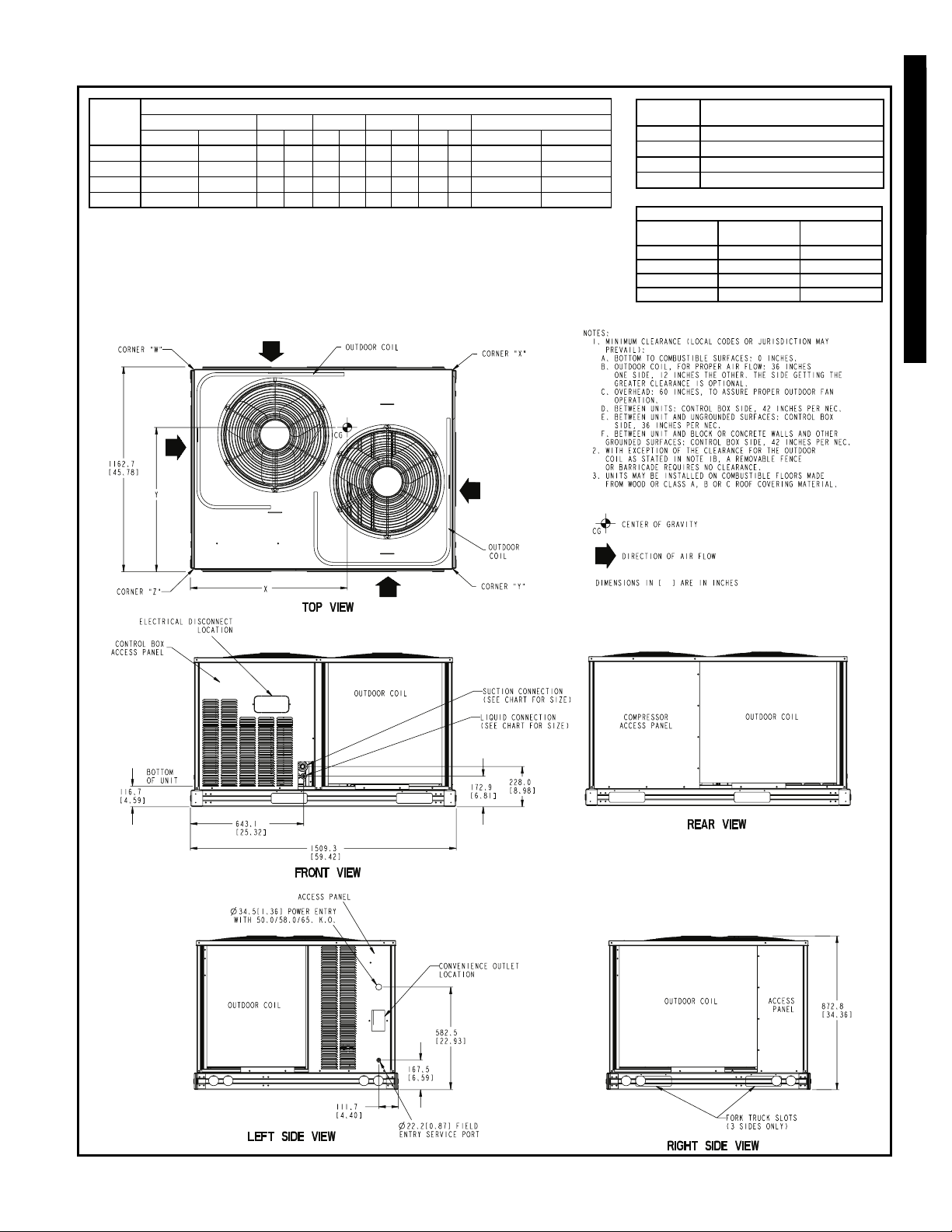
DIMENSIONS
569D072-120, 576C120, 569F120
50TFQ004-012
UNIT
Standard Unit Weight Corner W Corner X Corner Y Corner Z Center of Gravity
lb kglbkglbkglb kglbkg X mm [in.] Ymm[in.]
569D072 300 136 62 28 103 47 62 28 72 33 831.9 [32.75] 641.4 [25.25]
569D090 383 174 86 39 123 56 85 39 89 40 822.3 [32.38] 635.0 [25.00]
569D120 430 195 84 38 166 75 66 30 114 52 812.8 [32.00] 676.3 [26.63]
576C120 575 261 55 25 265 120 88 40 167 76 927.1 [36.50] 647.7 [25.50]
ALUMINUM COIL
UNIT
569D072 208/230-3-60, 460-3-60, 575-3-60
569D090 208/230-3-60, 460-3-60, 575-3-60
569D120 208/230-3-60, 460-3-60, 575-3-60
576C120 208/230-3-60, 460-3-60, 575-3-60
SERVICE VALVE CONNECTIONS
Unit
569D072 28.6 [1
569D090 28.6 [1
569D120 34.9 [1
576C120 34.9 [1
ELECTRICAL
CHARACTERISTICS
Suction
mm [in.]
1
/8]9.5[
1
/8]9.5[
3
/8] 12.7 [1/2]
3
/8] 12.7 [1/2]
Liquid
mm [in.]
3
/8]
3
/8]
569D072-120, 576C120
13
Page 14
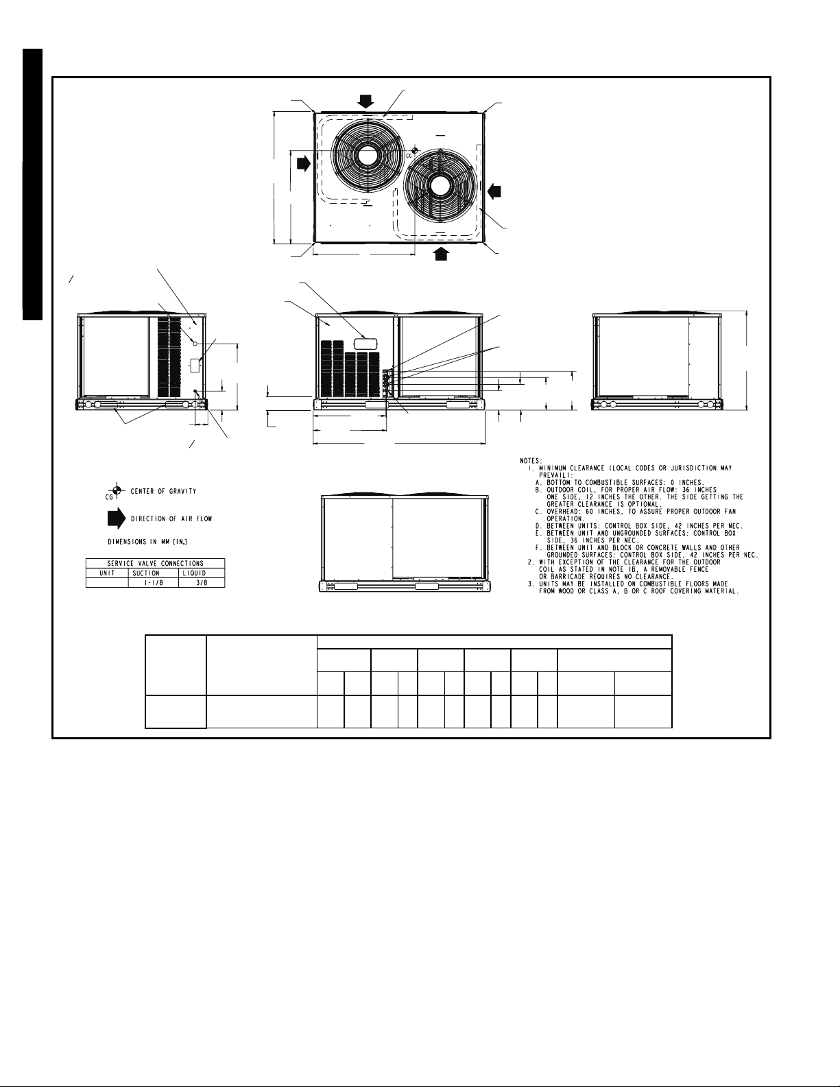
DIMENSIONS (cont)
O 34.5 [1.36]
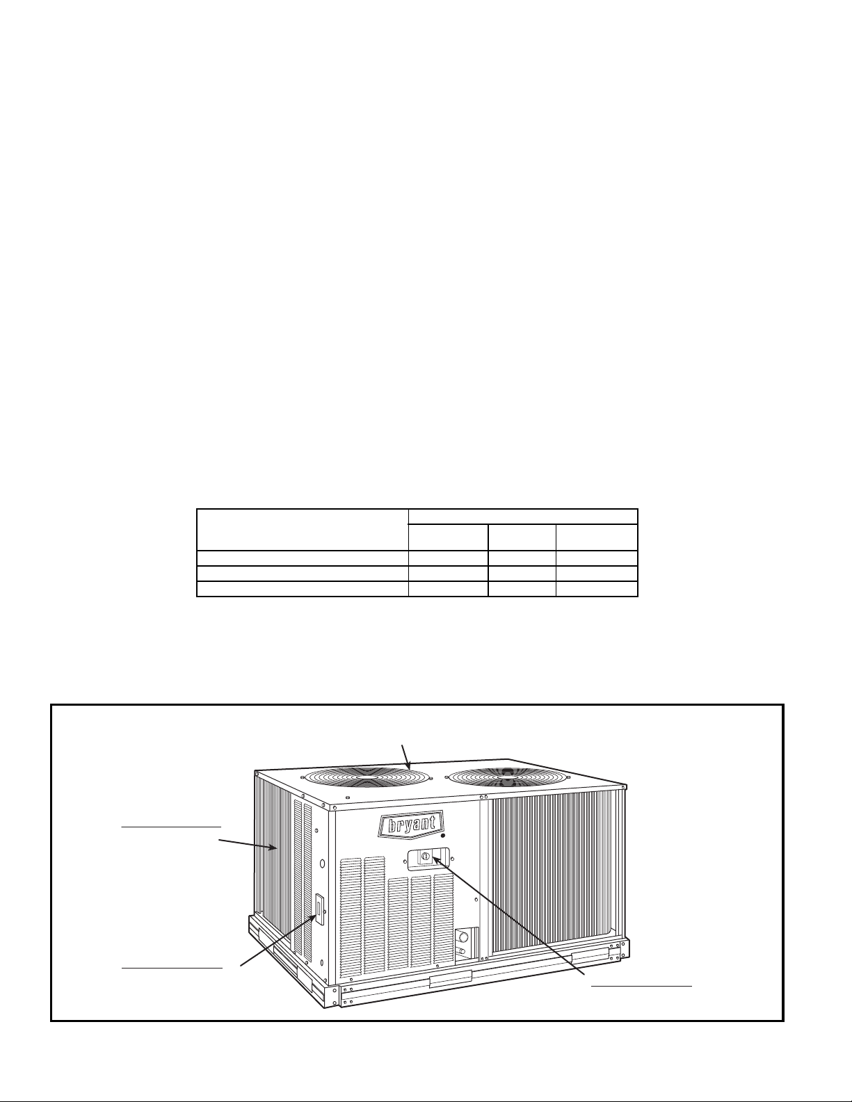
POWER ENTRY
50TFQ004-012
WITH 50.0/58.0/65.0 K.O.
569D072-120, 576C120, 569F120
OUTDOOR
FORK TRUCK SLOTS
(3 SIDES ONLY)
LEFT SIDE VIEW
ACCESS PANEL
COIL
CORNER “A”
CORNER “D”
CONTROL BOX
ACCESS PANEL
CONVENIENCE
OUTLET LOCATION
582.5
[22.93]
167.5
[6.59]
111.7
[4.40]
O 22.0 [0.87] FIELD
ENTRY SERVICE PORT
1162.7
[45.78]
Y
ELECTRICAL DISCONNECT
LOCATION
BOTTOM
OF UNIT
116.7
[4.59]
644.6
[25.38]
637.9
[25.11]
OUTDOOR COIL
X
TOP VIEW
OUTDOOR
LIQUID CONNECTION
(SEE CHART FOR SIZE)
1509.3
[59.42]
FRONT VIEW
COIL
CORNER “B”
OUTDOOR COIL
CORNER “C”
LIQUID
CONNECTION
(SEE CHART
FOR SIZE)
SUCTION
CONNECTION
(SEE CHART
FOR SIZE)
226.9
172.9
[8.93]
[6.81]
287.8
[11.33]
341.5
[13.45]
OUTDOOR
COIL
ACCESS
RIGHT SIDE VIEW
PANEL
872.8
[34.36]
569F120
(in.)
UNIT
569F120
(in.)
ELECTRICAL
CHARACTERISTICS
208/230-3-60,
400/460-3-50/60,
575-3-60
COMPRESSOR
ACCESS PANEL
OUTDOOR
COIL
REAR VIEW
ALUMINUM COIL
Std. Unit
Wt.
CornerACornerBCornerCCorner
D
lb kglbkglbkglbkglbkg
488 221 102 46 143 65 139 63 104 47
569F120
Center of
Gravity
X
mm [in.]Ymm [in.]
873.8
[34.4]
591.8
[23.3]
14
Page 15
569D072
SST (F)
TC 53.6 52.3 49.4 48.0 46.5 43.6
25
kW 4.24 4.49 5.02 5.31 5.60 6.24
SDT 101.0 106.0 115.0 120.0 125.0 135.0
TC 59.1 57.6 54.6 53.0 51.5 48.3
30
kW 4.33 4.57 5.10 5.39 5.69 6.33
SDT 102.0 107.0 117.0 122.0 126.0 136.0
TC 64.9 63.3 60.1 58.4 56.7 53.4
35
kW 4.42 4.67 5.20 5.49 5.79 6.43
SDT 104.0 109.0 118.0 123.0 128.0 138.0
TC 71.0 69.3 65.8 64.1 62.3 58.7
40
kW 4.53 4.77 5.31 5.60 5.90 6.55
SDT 106.0 110.0 120.0 125.0 129.0 139.0
TC 77.4 75.6 71.9 70.1 68.2 64.3
45
kW 4.65 4.89 5.43 5.72 6.02 6.68
SDT 107.0 112.0 122.0 126.0 131.0 141.0
TC 84.2 82.3 78.4 76.4 74.3 70.2
50
kW 4.78 5.03 5.56 5.86 6.16 6.81
SDT 109.0 114.0 123.0 128.0 133.0 142.0
569D090
SST (F)
TC 73.9 71.7 67.0 64.6 62.1 57.0
25
kW 5.81 6.14 6.84 7.21 7.58 8.36
SDT 98.6 104.0 114.0 118.0 123.0 133.0
TC 82.0 79.7 74.9 72.4 69.9 64.7
30
kW 5.88 6.21 6.90 7.28 7.65 8.46
SDT 99.6 104.0 114.0 119.0 124.0 134.0
TC 90.4 88.0 83.0 80.4 77.8 72.4
35
kW 5.98 6.31 7.02 7.40 7.78 8.59
SDT 101.0 106.0 115.0 120.0 125.0 135.0
TC 99.2 96.7 91.4 88.7 85.9 80.3
40
kW 6.09 6.43 7.14 7.53 7.92 8.74
SDT 103.0 107.0 117.0 122.0 126.0 136.0
TC 109.0 106.0 100.0 97.4 94.5 88.6
45
kW 6.22 6.56 7.28 7.68 8.07 8.91
SDT 104.0 109.0 119.0 123.0 128.0 138.0
TC 118.0 116.0 110.0 107.0 104.0 97.2
50
kW 6.36 6.70 7.43 7.83 8.23 9.09
SDT 106.0 111.0 120.0 125.0 130.0 139.0
569D120
SST (F)
TC 102.0 99.3 93.8 90.9 88.1 81.9
25
kW 8.04 8.38 9.13 9.55 9.95 10.85
SDT 101.0 106.0 116.0 121.0 126.0 136.0
TC 112.0 109.0 103.0 99.8 96.7 90.3
30
kW 8.26 8.60 9.31 9.65 10.05 10.95
SDT 103.0 107.0 117.0 12.02 127.0 136.0
TC 122.0 119.0 113.0 109.0 106.0 99.0
35
kW 8.52 8.85 9.55 9.95 10.35 11.15
SDT 104.0 109.0 118.0 123.0 128.0 137.0
TC 133.0 130.0 123.0 119.0 115.0 108.0
40
kW 8.81 9.15 9.85 10.25 10.55 11.35
SDT 106.0 110.0 120.0 125.0 129.0 139.0
TC 144.0 141.0 133.0 130.0 126.0 118.0
45
kW 9.12 9.45 10.15 10.55 10.85 11.65
SDT 108.0 112.0 122.0 126.0 131.0 140.0
TC 156.0 152.0 145.0 141.0 137.0 128.0
50
kW 9.45 9.85 10.55 10.85 11.25 12.05
SDT 109.0 114.0 123.0 128.0 133.0 142.0
Air Temperature Entering Condenser (F)
80 85 95 100 105 115
Air Temperature Entering Condenser (F)
80 85 95 100 105 115
Air Temperature Entering Condenser (F)
80 85 95 100 105 115
PERFORMANCE DATA
CONDENSING UNIT RATINGS
576C120
SST (F)
TC 89.0 85.1 77.4 73.6 69.7 62.2
25
kW 7.52 7.79 8.29 8.49 8.70 9.02
SDT 103.0 108.0 118.0 123.0 128.0 138.0
TC 101.0 96.6 88.5 84.4 80.3 72.2
30
kW 7.76 8.07 8.64 8.89 9.14 9.55
SDT 104.0 108.0 118.0 123.0 128.0 138.0
TC 113.0 109.0 100.0 95.8 91.5 83.0
35
kW 8.01 8.36 8.99 9.28 9.55 10.05
SDT 105.0 109.0 119.0 124.0 128.0 138.0
TC 125.0 121.0 112.0 107.0 103.0 94.1
40
kW 8.29 8.66 9.35 9.65 9.95 10.55
SDT 106.0 111.0 120.0 125.0 129.0 139.0
TC 138.0 133.0 124.0 119.0 115.0 106.0
45
kW 8.57 8.97 9.75 10.05 10.50 11.05
SDT 108.0 113.0 122.0 127.0 131.0 140.0
TC 152.0 147.0 137.0 132.0 127.0 117.0
50
kW 8.85 9.28 10.15 10.45 10.90 11.55
SDT 111.0 115.0 124.0 129.0 133.0 142.0
569F120
SST (F)
TC 90.5 87.9 82.6 79.8 76.9 71.1
25
kW 7.75 8.17 9.05 9.52 10.00 11.00
SDT 100.0 105.0 115.0 120.0 125.0 135.0
TC 100.0 97.8 92.2 89.3 86.3 80.2
30
kW 7.79 8.21 9.09 9.57 10.10 11.10
SDT 101.0 106.0 116.0 120.0 125.0 135.0
TC 111.0 108.0 102.0 99.0 96.0 89.7
35
kW 7.89 8.30 9.18 9.66 10.10 11.20
SDT 102.0 107.0 116.0 121.0 126.0 136.0
TC 122.0 119.0 112.0 109.0 106.0 99.4
40
kW 8.01 8.42 9.31 9.79 10.30 11.30
SDT 104.0 108.0 118.0 123.0 127.0 137.0
TC 133.0 130.0 123.0 120.0 116.0 109.0
45
kW 8.15 8.57 9.46 9.95 10.40 11.50
SDT 105.0 110.0 120.0 124.0 129.0 138.0
TC 145.0 141.0 134.0 131.0 127.0 120.0
50
kW 8.30 8.72 9.63 10.10 10.60 11.70
SDT 107.0 112.0 121.0 126.0 131.0 140.0
kW—Compressor Power
SDT — Saturated Discharge Temperature at Compressor (F)
SST — Saturated Suction Temperature (F)
TC — Gross Cooling Capacity (1000 Btuh)
Air Temperature Entering Condenser (F)
80 85 95 100 105 115
Air Temperature Entering Condenser (F)
80 85 95 100 105 115
LEGEND
569D072-120, 576C120, 569F120
50TFQ004-012
15
Page 16
569D072/524A-C072 WITH HIGH-CAPACITY 4-ROW COIL
50TFQ004-012
569D072-120, 576C120, 569F120
Tem p ( F)
Air Entering
Condenser
(Edb)
80
85
95
100
105
115
57 62 67 72 57 62 67 72 57 62 67 72
TC 66.0 68.6 74.3 80.7 72.0 72.6 77.7 84.1 76.2 76.2 79.9 86.2
SHC 66.0 60.9 51.0 40.8 72.0 70.5 58.6 45.5 76.2 76.2 65.7 50.0
kW 4.45 4.49 4.60 4.71 4.55 4.57 4.66 4.78 4.63 4.63 4.70 4.82
TC 65.1 67.5 73.1 79.3 71.0 71.4 76.3 82.6 75.0 75.1 78.5 84.6
SHC 65.1 60.3 50.5 40.3 71.0 69.8 58.1 45.0 75.0 75.1 65.2 49.5
kW 4.72 4.76 4.87 4.99 4.83 4.84 4.93 5.05 4.91 4.90 4.97 5.09
TC 63.3 65.2 70.6 76.7 68.9 69.1 73.6 79.7 72.8 72.8 75.7 81.6
SHC 63.3 59.2 49.4 39.3 68.9 68.3 57.0 44.0 72.8 72.8 64.0 48.5
kW 5.26 5.30 5.41 5.53 5.37 5.38 5.47 5.60 5.45 5.45 5.51 5.64
TC 62.3 64.0 69.2 75.2 67.7 67.9 72.2 78.2 71.5 71.5 74.2 80.0
SHC 62.3 58.6 48.9 38.8 67.7 67.4 56.5 43.5 71.5 71.5 63.4 47.9
kW 5.57 5.61 5.71 5.84 5.68 5.68 5.78 5.90 5.76 5.76 5.82 5.95
TC 61.3 62.8 67.9 73.8 66.6 66.7 70.7 76.6 70.3 70.3 72.7 78.4
SHC 61.3 58.0 48.3 38.2 66.6 66.6 55.9 42.9 70.3 70.3 62.8 47.4
kW 5.88 5.91 6.02 6.15 5.99 5.99 6.08 6.21 6.07 6.08 6.12 6.26
TC 59.3 60.5 65.2 70.9 64.4 64.3 67.8 73.5 67.9 67.9 69.7 75.2
SHC 59.3 56.8 47.2 37.2 64.4 64.3 54.8 41.9 67.9 67.9 61.6 46.4
kW 6.51 6.53 6.63 6.77 6.61 6.61 6.70 6.83 6.69 6.70 6.74 6.88
1800 2400 3000
PERFORMANCE DATA (cont)
COMBINATION RATINGS*
UNIT 569D072
Evaporator Air — Cfm
Evaporator Air — Ewb (F)
569D072/524A-B072 WITH STANDARD 3-ROW COIL
Tem p ( F)
Air Entering
Condenser
(Edb)
TC 63.4 66.1 71.7 77.8 69.0 69.8 74.9 81.1 72.9 72.9 76.9 83.1
80
85
95
100
105
115
Edb — Entering Dry Bulb
Ewb — Entering Wet Bulb
kW—Compressor Motor Power Input
SHC — Sensible Heat Capacity (1000 Btuh) Gross
TC — Total Capacity (1000 Btuh) Gross
*Combinations on this page are E
SHC 63.4 58.4 49.0 39.2 69.0 67.2 56.0 43.6 72.9 72.9 62.5 47.6
kW 4.40 4.45 4.55 4.66 4.50 4.52 4.60 4.72 4.57 4.57 4.64 4.76
TC 62.5 65.1 70.5 76.6 68.0 68.7 73.6 79.7 71.9 71.9 75.6 81.7
SHC 62.5 57.9 48.5 38.8 68.0 66.6 55.5 43.1 71.9 71.9 62.0 47.2
kW 4.67 4.72 4.82 4.93 4.77 4.79 4.88 4.99 4.84 4.84 4.91 5.03
TC 60.8 62.9 68.2 74.1 66.1 66.5 71.1 77.0 69.7 69.8 73.1 78.9
SHC 60.8 56.8 47.5 37.9 66.1 65.2 54.6 42.2 69.7 69.8 60.9 46.2
kW 5.22 5.26 5.36 5.48 5.32 5.33 5.42 5.54 5.39 5.39 5.46 5.58
TC 59.9 61.8 67.0 72.8 65.1 65.4 69.8 75.6 68.6 68.6 71.7 77.4
SHC 59.9 56.3 47.0 37.4 65.1 64.4 54.0 41.7 68.6 68.6 60.4 45.7
kW 5.53 5.56 5.67 5.79 5.63 5.63 5.73 5.85 5.70 5.70 5.76 5.89
TC 59.0 60.7 65.7 71.4 64.0 64.2 68.5 74.1 67.5 67.5 70.3 75.9
SHC 59.0 55.7 46.5 36.9 64.0 63.7 53.5 41.2 67.5 67.5 59.8 45.2
kW 5.84 5.87 5.98 6.10 5.94 5.94 6.03 6.16 6.01 6.01 6.07 6.20
TC 57.1 58.4 63.3 68.7 61.9 61.9 65.8 71.3 65.2 65.2 67.4 72.9
SHC 57.1 54.6 45.5 35.9 61.9 61.9 52.4 40.2 65.2 65.2 58.7 44.2
kW 6.46 6.48 6.59 6.72 6.57 6.56 6.65 6.78 6.64 6.63 6.68 6.82
57 62 67 72 57 62 67 72 57 62 67 72
LEGEND
1800 2400 3000
NERGY STAR ® compliant.
Evaporator Air — Cfm
Evaporator Air — Ewb (F)
16
Page 17
PERFORMANCE DATA (cont)
COMBINATION RATINGS (cont)
569D072/524A-C090 WITH HIGH-CAPACITY 4-ROW COIL*
Tem p ( F)
Air Entering
Condenser
(Edb)
80
85
95
100
105
115
57 62 67 72 57 62 67 72 57 62 67 72
TC 71.9 72.9 78.3 84.8 77.7 77.7 81.3 87.6 81.6 81.6 83.4 89.4
SHC 71.9 69.5 57.7 45.1 77.7 77.7 67.0 50.9 81.6 81.6 75.2 56.4
kW 4.55 4.57 4.67 4.79 4.66 4.66 4.73 4.85 4.73 4.73 4.77 4.89
TC 70.9 71.7 76.9 83.3 76.5 76.5 79.8 86.1 80.3 80.3 81.9 87.8
SHC 70.9 68.8 57.2 44.6 76.5 76.5 66.4 50.3 80.3 80.3 74.6 55.9
kW 4.83 4.84 4.94 5.07 4.93 4.93 5.00 5.12 5.01 5.01 5.04 5.16
TC 68.8 69.3 74.2 80.4 74.1 74.1 76.9 82.9 77.7 77.8 79.0 84.5
SHC 68.8 67.5 56.1 43.5 74.1 74.1 65.2 49.3 77.7 77.8 73.3 54.8
kW 5.37 5.38 5.48 5.61 5.48 5.48 5.54 5.66 5.55 5.56 5.58 5.70
TC 67.7 68.0 72.8 78.8 72.8 72.9 75.4 81.3 76.4 76.4 77.4 82.8
SHC 67.7 66.8 55.5 43.0 72.8 72.9 64.6 48.8 76.4 76.4 72.5 54.3
kW 5.68 5.69 5.79 5.92 5.79 5.79 5.85 5.97 5.87 5.87 5.89 6.01
TC 66.5 66.8 71.3 77.3 71.6 71.6 73.9 79.6 75.0 75.0 75.9 81.1
SHC 66.5 66.0 54.9 42.5 71.6 71.6 64.0 48.2 75.0 75.0 71.8 53.7
kW 5.99 6.00 6.09 6.23 6.10 6.10 6.15 6.28 6.18 6.18 6.20 6.32
TC 64.3 64.3 68.4 74.2 69.0 69.1 70.8 76.2 72.3 72.3 72.7 77.7
SHC 64.3 64.3 53.8 41.4 69.0 69.1 62.8 47.1 72.3 72.3 70.3 52.6
kW 6.61 6.61 6.71 6.85 6.73 6.73 6.77 6.90 6.81 6.8 6.81 6.94
2400 3000 3750
UNIT 569D072 (cont)
Evaporator Air — Cfm
Evaporator Air — Ewb (F)
569D072-120, 576C120, 569F120
50TFQ004-012
569D072/524A-B090 WITH STANDARD 3-ROW COIL
Tem p ( F)
Air Entering
Condenser
(Edb)
TC 68.4 69.5 74.8 81.0 73.6 73.6 77.6 83.8 77.3 77.3 79.5 85.5
80
85
95
100
105
115
Edb — Entering Dry Bulb
Ewb — Entering Wet Bulb
kW—Compressor Motor Power Input
SHC — Sensible Heat Capacity (1000 Btuh) Gross
TC — Total Capacity (1000 Btuh) Gross
*This combination is E
SHC 68.4 65.8 54.8 42.9 73.6 73.6 63.1 48.1 77.3 77.3 70.4 52.9
kW 4.49 4.51 4.61 4.72 4.58 4.58 4.65 4.77 4.65 4.65 4.69 4.81
TC 67.4 68.4 73.6 79.7 72.6 72.6 76.3 82.4 76.1 76.1 78.2 84.0
SHC 67.4 65.2 54.3 42.4 72.6 72.6 62.6 47.6 76.1 76.1 69.8 52.4
kW 4.76 4.78 4.88 5.00 4.86 4.86 4.93 5.05 4.92 4.92 4.96 5.08
TC 65.5 66.2 71.1 77.1 70.4 70.5 73.7 79.5 73.8 73.8 75.5 81.1
SHC 65.5 64.0 53.3 41.5 70.4 70.5 61.5 46.6 73.8 73.8 68.7 51.4
kW 5.31 5.32 5.42 5.54 5.40 5.40 5.47 5.59 5.47 5.47 5.51 5.62
TC 64.5 65.1 69.7 75.6 69.3 69.3 72.3 78.0 72.6 72.6 74.0 79.5
SHC 64.5 63.3 52.8 41.0 69.3 69.3 60.9 46.1 72.6 72.6 68.0 50.9
kW 5.62 5.63 5.72 5.85 5.71 5.72 5.78 5.90 5.78 5.78 5.82 5.93
TC 63.4 63.9 68.4 74.1 68.1 68.1 70.9 76.5 71.4 71.4 72.6 77.9
SHC 63.4 62.5 52.2 40.5 68.1 68.1 60.4 45.6 71.4 71.4 67.3 50.4
kW 5.93 5.94 6.03 6.16 6.03 6.03 6.08 6.21 6.10 6.10 6.12 6.24
TC 61.4 61.6 65.8 71.2 65.9 65.8 68.0 73.4 68.9 68.9 69.7 74.8
SHC 61.4 61.1 51.2 39.4 65.9 65.8 59.2 44.6 68.9 68.9 66.0 49.4
kW 6.55 6.55 6.64 6.78 6.65 6.65 6.70 6.83 6.72 6.73 6.74 6.86
57 62 67 72 57 62 67 72 57 62 67 72
LEGEND
NERGY STA R ® compliant.
2400 3000 3750
Evaporator Air — Cfm
Evaporator Air — Ewb (F)
17
Page 18
569D090/524A-C072 WITH HIGH-CAPACITY 4-ROW COIL*
50TFQ004-012
569D072-120, 576C120, 569F120
Tem p ( F)
Air Entering
Condenser
(Edb)
80
85
95
100
105
115
57 62 67 72 57 62 67 72 57 62 67 72
TC 78.9 85.1 92.8 101.0 87.0 90.7 98.3 106.0 93.0 94.7 102.0 110.0
SHC 77.9 69.0 59.0 48.7 87.0 79.9 66.9 53.6 93.0 89.3 74.2 58.0
kW 5.75 5.78 5.85 5.94 5.79 5.83 5.91 6.01 5.85 5.87 5.96 6.06
TC 77.6 83.6 91.3 99.3 85.7 89.2 96.6 105.0 91.6 93.1 100.0 108.0
SHC 77.0 68.3 58.3 48.0 85.7 79.1 66.3 52.9 91.6 88.4 73.5 57.4
kW 6.10 6.13 6.20 6.30 6.14 6.18 6.26 6.37 6.20 6.22 6.31 6.41
TC 75.1 80.8 88.3 96.1 83.2 86.1 93.3 101.0 88.9 89.9 96.5 104.0
SHC 75.1 66.8 56.9 46.7 83.2 77.6 64.9 51.6 88.9 86.7 72.2 56.1
kW 6.80 6.82 6.90 7.00 6.85 6.87 6.96 7.08 6.91 6.92 7.01 7.12
TC 73.9 79.2 86.6 94.4 81.8 84.4 91.4 99.2 87.4 88.2 94.5 102.0
SHC 73.8 66.0 56.2 46.1 81.8 76.7 64.1 50.9 87.4 85.7 71.4 55.3
kW 7.20 7.21 7.29 7.40 7.24 7.26 7.36 7.47 7.30 7.31 7.40 7.52
TC 72.6 77.6 85.0 92.6 80.4 82.7 89.6 97.3 85.9 86.5 92.6 100.0
SHC 72.6 65.3 55.5 45.4 80.4 75.9 63.4 50.2 85.9 84.7 70.7 54.6
kW 7.59 7.60 7.68 7.79 7.64 7.66 7.75 7.87 7.70 7.71 7.80 7.92
TC 70.1 74.5 81.7 89.1 77.7 79.4 86.0 93.5 82.9 83.1 88.8 96.2
SHC 70.1 63.7 54.0 44.0 77.7 74.3 61.9 48.8 82.9 82.7 69.2 53.2
kW 8.38 8.38 8.47 8.58 8.43 8.44 8.53 8.66 8.48 8.49 8.58 8.71
1800 2400 3000
PERFORMANCE DATA (cont)
COMBINATION RATINGS (cont)
UNIT 569D090
Evaporator Air — Cfm
Evaporator Air — Ewb (F)
569D090/524A-B072 WITH STANDARD 3-ROW COIL
Tem p ( F)
Air Entering
Condenser
(Edb)
TC 75.3 81.2 88.5 96.1 82.5 86.4 93.6 101.0 88.0 89.9 96.8 104.0
80
85
95
100
105
115
Edb — Entering Dry Bulb
Ewb — Entering Wet Bulb
kW—Compressor Motor Power Input
SHC — Sensible Heat Capacity (1000 Btuh) Gross
TC — Total Capacity (1000 Btuh) Gross
*This combination is E
SHC 74.3 65.8 56.3 46.4 82.5 75.7 63.5 50.9 88.0 84.1 70.0 54.9
kW 5.77 5.82 5.91 6.00 5.84 5.88 5.97 6.07 5.90 5.93 6.01 6.12
TC 74.2 79.8 87.1 94.6 81.3 84.9 92.0 99.5 86.7 88.4 95.2 103.0
SHC 73.4 65.2 55.6 45.8 81.3 75.0 62.8 50.2 86.7 83.3 69.4 54.3
kW 6.12 6.18 6.27 6.37 6.20 6.24 6.33 6.44 6.26 6.28 6.38 6.48
TC 71.8 77.2 84.2 91.6 79.0 82.0 88.8 96.2 84.1 85.4 91.9 99.2
SHC 71.6 63.8 54.3 44.6 79.0 73.6 61.5 49.0 84.1 81.7 68.1 53.0
kW 6.83 6.89 6.98 7.10 6.91 6.95 7.05 7.17 6.99 7.00 7.10 7.22
TC 70.6 75.7 82.6 89.9 77.7 80.4 87.1 94.4 82.7 83.8 90.0 97.3
SHC 70.5 63.1 53.6 43.9 77.7 72.8 60.8 48.3 82.7 80.7 67.4 52.3
kW 7.22 7.28 7.38 7.50 7.31 7.35 7.45 7.58 7.39 7.40 7.51 7.63
TC 69.4 74.2 81.1 88.3 76.4 78.8 85.4 92.6 81.3 82.2 88.2 95.4
SHC 69.4 62.4 53.0 43.3 76.4 72.0 60.1 47.7 81.3 79.8 66.7 51.7
kW 7.61 7.67 7.78 7.91 7.70 7.75 7.86 7.99 7.79 7.80 7.91 8.04
TC 67.0 71.3 78.0 85.0 73.8 75.6 82.0 89.0 78.5 78.9 84.6 91.7
SHC 67.0 60.9 51.6 41.9 73.8 70.5 58.7 46.4 78.5 77.9 65.3 50.3
kW 8.39 8.45 8.59 8.73 8.49 8.54 8.66 8.80 8.59 8.60 8.71 8.86
57 62 67 72 57 62 67 72 57 62 67 72
LEGEND
NERGY STA R ® compliant.
1800 2400 3000
Evaporator Air — Cfm
Evaporator Air — Ewb (F)
18
Page 19
PERFORMANCE DATA (cont)
COMBINATION RATINGS (cont)
569D090/524A-C090 WITH HIGH-CAPACITY 4-ROW COIL*
Tem p ( F)
Air Entering
Condenser
(Edb)
TC 86.0 90.4 98.0 106.0 94.1 95.7 103.0 111.0 96.9 97.8 104.0 112.0
80
85
95
100
105
115
SHC 86.0 78.0 65.6 52.8 94.1 90.3 75.0 58.5 96.9 94.8 79.3 61.1
kW 5.78 5.83 5.91 6.01 5.86 5.88 5.97 6.07 5.90 5.91 5.98 6.09
TC 84.8 88.9 96.4 104.0 92.7 94.1 101.0 109.0 95.4 96.2 102.0 110.0
SHC 84.8 77.3 64.9 52.2 92.7 89.4 74.2 57.8 95.4 93.7 78.5 60.5
kW 6.14 6.18 6.26 6.37 6.22 6.23 6.32 6.42 6.25 6.26 6.34 6.44
TC 82.3 85.8 93.1 101.0 90.0 90.9 97.3 105.0 92.6 93.1 98.7 106.0
SHC 82.3 75.8 63.5 50.9 90.0 87.7 72.8 56.5 92.6 91.4 77.1 59.2
kW 6.85 6.88 6.96 7.07 6.92 6.93 7.02 7.13 6.96 6.96 7.04 7.15
TC 81.0 84.2 91.3 99.1 88.5 89.2 95.4 103.0 91.0 91.4 96.8 104.0
SHC 81.0 75.0 62.8 50.2 88.5 86.7 72.1 55.8 91.0 90.1 76.4 58.5
kW 7.24 7.26 7.36 7.47 7.32 7.33 7.41 7.53 7.35 7.36 7.43 7.55
TC 79.6 82.5 89.6 97.2 87.0 87.5 93.5 101.0 89.5 89.7 94.9 102.0
SHC 79.6 74.1 62.1 49.5 87.0 85.7 71.4 55.2 89.5 88.8 75.6 57.8
kW 7.63 7.65 7.75 7.87 7.71 7.72 7.81 7.93 7.75 7.75 7.83 7.95
TC 77.0 79.2 86.0 93.5 83.9 84.1 89.8 97.2 86.3 86.4 91.0 98.3
SHC 77.0 72.5 60.6 48.1 83.9 83.7 69.9 53.8 86.3 86.2 74.1 56.4
kW 8.41 8.42 8.53 8.66 8.50 8.50 8.60 8.73 8.54 8.54 8.62 8.75
57 62 67 72 57 62 67 72 57 62 67 72
2205 3000 3750
UNIT 569D090 (cont)
Evaporator Air — Cfm
Evaporator Air — Ewb (F)
569D072-120, 576C120, 569F120
50TFQ004-012
569D090/524A-B090 WITH STANDARD 3-ROW COIL
Tem p ( F)
Air Entering
Condenser
(Edb)
TC 81.7 85.9 93.2 101.0 89.0 90.8 97.5 105.0 91.6 92.6 98.8 106.0
80
85
95
100
105
115
Edb — Entering Dry Bulb
Ewb — Entering Wet Bulb
kW—Compressor Motor Power Input
SHC — Sensible Heat Capacity (1000 Btuh) Gross
TC — Total Capacity (1000 Btuh) Gross
*This combination is E
SHC 81.7 74.2 62.4 50.2 89.0 85.2 70.9 55.4 91.6 89.4 74.7 57.7
kW 5.83 5.88 5.97 6.07 5.92 5.94 6.02 6.12 5.95 5.96 6.04 6.14
TC 80.6 84.5 91.6 99.2 87.7 89.3 95.8 103.0 90.2 91.1 97.1 105.0
SHC 80.6 73.5 61.7 49.6 87.7 84.5 70.2 54.8 90.2 88.4 74.1 57.1
kW 6.19 6.23 6.33 6.43 6.28 6.30 6.39 6.49 6.31 6.32 6.40 6.51
TC 78.3 81.7 88.5 95.9 85.2 86.3 92.5 99.9 87.6 88.2 93.8 101.0
SHC 78.3 72.1 60.4 48.4 85.2 82.9 69.0 53.6 87.6 86.4 72.8 55.9
kW 6.90 6.95 7.05 7.17 7.00 7.02 7.11 7.23 7.04 7.05 7.13 7.25
TC 77.0 80.1 86.9 94.2 83.7 84.7 90.7 98.0 86.1 86.6 91.9 99.1
SHC 77.0 71.3 59.8 47.7 83.7 81.9 68.3 52.9 86.1 85.2 72.1 55.2
kW 7.30 7.34 7.45 7.57 7.40 7.42 7.52 7.64 7.44 7.45 7.54 7.66
TC 75.7 78.6 85.2 92.4 82.3 83.0 88.9 96.1 84.6 85.0 90.1 97.2
SHC 75.7 70.6 59.1 47.0 82.3 80.9 67.6 52.2 84.6 83.9 71.4 54.6
kW 7.69 7.74 7.86 7.98 7.80 7.82 7.92 8.05 7.84 7.85 7.94 8.07
TC 73.2 75.4 81.9 88.8 79.5 79.8 85.3 92.3 81.7 81.8 86.4 93.3
SHC 73.2 69.0 57.7 45.7 79.5 79.0 66.1 50.9 81.7 81.4 70.0 53.2
kW 8.48 8.53 8.67 8.79 8.61 8.61 8.73 8.87 8.65 8.65 8.75 8.89
57 62 67 72 57 62 67 72 57 62 67 72
LEGEND
NERGY STA R ® compliant.
2205 3000 3750
Evaporator Air — Cfm
Evaporator Air — Ewb (F)
19
Page 20

569D120/524A-C120 WITH HIGH-CAPACITY 4-ROW COIL
50TFQ004-012
569D072-120, 576C120, 569F120
Tem p ( F)
Air Entering
Condenser
(Edb)
TC 117.0 122.0 132.0 142.0 127.0 129.0 138.0 148.0 134.0 134.0 141.0 151.0
80
SHC 117.0 106.0 88.4 70.9 127.0 122.0 101.0 78.6 134.0 134.0 113.0 85.9
kW 8.34 8.48 8.74 9.02 8.61 8.66 8.89 9.18 8.81 8.80 9.00 9.28
TC 115.0 120.0 129.0 140.0 125.0 127.0 135.0 145.0 132.0 132.0 139.0 148.0
85
SHC 115.0 104.0 87.5 70.0 125.0 121.0 100.0 77.6 132.0 132.0 112.0 84.9
kW 8.72 8.85 9.11 9.40 8.99 9.04 9.27 9.56 9.19 9.19 9.38 9.67
TC 112.0 116.0 125.0 135.0 121.0 122.0 130.0 140.0 128.0 128.0 134.0 143.0
95
SHC 112.0 102.0 85.5 68.2 121.0 119.0 98.2 75.8 128.0 128.0 110.0 83.1
kW 9.49 9.60 9.86 10.20 9.76 9.79 10.00 10.30 9.96 9.95 10.10 10.40
100
105
115
TC 110.0 113.0 122.0 132.0 119.0 120.0 127.0 137.0 125.0 125.0 131.0 140.0
SHC 110.0 101.0 84.4 67.1 119.0 117.0 97.1 74.8 125.0 125.0 109.0 82.1
kW 9.90 10.00 10.30 10.60 10.20 10.20 10.40 10.70 10.40 10.40 10.50 10.80
TC 108.0 111.0 120.0 129.0 117.0 117.0 125.0 134.0 123.0 123.0 128.0 137.0
SHC 108.0 100.0 83.3 66.1 117.0 116.0 96.0 73.7 123.0 123.0 108.0 81.0
kW 10.30 10.40 10.70 11.00 10.60 10.60 10.80 11.10 10.80 10.80 10.90 11.20
TC 104.0 106.0 114.0 124.0 112.0 112.0 119.0 128.0 118.0 118.0 122.0 131.0
SHC 104.0 97.7 81.2 64.0 112.0 112.0 93.8 71.7 118.0 118.0 105.0 78.9
kW 11.10 11.20 11.50 11.70 11.40 11.40 11.60 11.90 11.60 11.60 11.70 12.00
57 62 67 72 57 62 67 72 57 62 67 72
3000 4000 5000
PERFORMANCE DATA (cont)
COMBINATION RATINGS (cont)
UNIT 569D120
Evaporator Air — Cfm
Evaporator Air — Ewb (F)
569D120/524A-B120 WITH STANDARD 3-ROW COIL
Tem p ( F)
Air Entering
Condenser
(Edb)
TC 110.0 115.0 124.0 134.0 119.0 121.0 130.0 139.0 126.0 126.0 133.0 143.0
80
SHC 110.0 99.4 83.3 66.8 119.0 114.0 94.6 73.6 126.0 125.0 105.0 79.9
kW 8.19 8.32 8.55 8.82 8.41 8.48 8.70 8.96 8.59 8.60 8.80 9.06
TC 108.0 113.0 122.0 132.0 117.0 119.0 128.0 137.0 124.0 124.0 131.0 140.0
85
SHC 108.0 98.4 82.4 66.0 117.0 113.0 93.7 72.8 124.0 123.0 104.0 79.0
kW 8.57 8.70 8.93 9.20 8.80 8.85 9.08 9.35 8.97 8.98 9.17 9.44
TC 105.0 110.0 118.0 127.0 114.0 115.0 123.0 132.0 120.0 120.0 126.0 135.0
95
SHC 105.0 96.6 80.7 64.3 114.0 111.0 91.9 71.1 120.0 120.0 102.0 77.3
kW 9.34 9.45 9.69 9.96 9.57 9.61 9.83 10.10 9.73 9.74 9.93 10.20
100
105
115
Edb — Entering Dry Bulb
Ewb — Entering Wet Bulb
kW—Compressor Motor Power Input
SHC — Sensible Heat Capacity (1000 Btuh) Gross
TC — Total Capacity (1000 Btuh) Gross
TC 104.0 107.0 116.0 125.0 112.0 113.0 121.0 130.0 118.0 118.0 124.0 132.0
SHC 104.0 95.5 79.7 63.4 112.0 109.0 90.9 70.2 118.0 118.0 101.0 76.4
kW 9.76 9.86 10.10 10.40 9.98 10.00 10.20 10.50 10.10 10.10 10.30 10.60
TC 102.0 105.0 114.0 122.0 110.0 111.0 118.0 127.0 116.0 116.0 121.0 130.0
SHC 102.0 94.4 78.7 62.4 110.0 108.0 89.9 69.2 116.0 116.0 100.0 75.5
kW 10.20 10.30 10.5 10.80 10.40 10.40 10.60 10.90 10.60 10.60 10.70 11.00
TC 98.4 101.0 109.0 117.0 106.0 106.0 113.0 122.0 111.0 111.0 116.0 124.0
SHC 98.4 92.2 76.7 60.5 106.0 105.0 87.8 67.3 111.0 111.0 97.9 73.6
kW 11.00 11.10 11.30 11.60 11.20 11.20 11.40 11.70 11.40 11.40 11.50 11.80
57 62 67 72 57 62 67 72 57 62 67 72
LEGEND
3000 4000 5000
Evaporator Air — Cfm
Evaporator Air — Ewb (F)
20
Page 21
PERFORMANCE DATA (cont)
COMBINATION RATINGS (cont)
569D120/524A-C150 WITH HIGH-CAPACITY 4-ROW COIL
Tem p ( F)
Air Entering
Condenser
(Edb)
80
85
95
100
105
115
TC 126.0 129.0 138.0 149.0 136.0 136.0 143.0 153.0 142.0 142.0 147.0 156.0
SHC 126.0 119.0 98.7 77.4 136.0 135.0 114.0 86.5 142.0 142.0 127.0 95.0
kW 8.60 8.68 8.94 9.23 8.87 8.87 9.08 9.37 9.06 9.05 9.18 9.46
TC 124.0 127.0 136.0 146.0 134.0 134.0 141.0 151.0 140.0 140.0 144.0 154.0
SHC 124.0 118.0 97.7 76.5 134.0 133.0 113.0 85.6 140.0 140.0 126.0 94.1
kW 8.98 9.05 9.31 9.61 9.25 9.25 9.46 9.76 9.44 9.44 9.56 9.84
TC 120.0 122.0 131.0 141.0 129.0 129.0 136.0 145.0 136.0 136.0 139.0 148.0
SHC 120.0 116.0 95.7 74.6 129.0 129.0 111.0 83.8 136.0 136.0 124.0 92.3
kW 9.74 9.80 10.10 10.40 10.00 10.00 10.20 10.50 10.20 10.20 10.30 10.60
TC 118.0 120.0 128.0 138.0 127.0 127.0 133.0 142.0 133.0 133.0 136.0 145.0
SHC 118.0 114.0 94.6 73.6 127.0 127.0 109.0 82.7 133.0 133.0 123.0 91.2
kW 10.20 10.20 10.50 10.80 10.40 10.40 10.60 10.90 10.60 10.60 10.70 11.00
TC 116.0 117.0 126.0 135.0 125.0 125.0 130.0 139.0 130.0 130.0 133.0 142.0
SHC 116.0 113.0 93.5 72.6 125.0 125.0 108.0 81.6 130.0 130.0 121.0 90.1
kW 10.60 10.60 10.90 11.20 10.80 10.80 11.00 11.30 11.00 11.00 11.10 11.40
TC 112.0 112.0 120.0 129.0 120.0 120.0 124.0 133.0 125.0 125.0 127.0 135.0
SHC 112.0 110.0 91.4 70.5 120.0 120.0 106.0 79.5 125.0 125.0 119.0 87.9
kW 11.40 11.40 11.70 12.00 11.60 11.70 11.80 12.10 11.80 11.80 11.90 12.20
57 62 67 72 57 62 67 72 57 62 67 72
3750 5000 6250
UNIT 569D120 (cont)
Evaporator Air — Cfm
Evaporator Air — Ewb (F)
569D072-120, 576C120, 569F120
50TFQ004-012
569D120/524A-B150 WITH STANDARD 3-ROW COIL
Tem p ( F)
Air Entering
Condenser
(Edb)
80
85
95
100
105
115
Edb — Entering Dry Bulb
Ewb — Entering Wet Bulb
kW—Compressor Motor Power Input
SHC — Sensible Heat Capacity (1000 Btuh) Gross
TC — Total Capacity (1000 Btuh) Gross
TC 119.0 123.0 132.0 142.0 128.0 129.0 137.0 147.0 135.0 135.0 140.0 150.0
SHC 119.0 112.0 93.2 73.4 128.0 127.0 106.0 81.4 135.0 135.0 118.0 88.6
kW 8.42 8.51 8.77 9.05 8.66 8.68 8.90 9.18 8.84 8.84 8.99 9.27
TC 118.0 121.0 130.0 140.0 126.0 127.0 135.0 144.0 133.0 133.0 138.0 147.0
SHC 118.0 111.0 92.3 72.5 126.0 126.0 105.0 80.5 133.0 133.0 117.0 87.8
kW 8.80 8.89 9.14 9.43 9.05 9.06 9.28 9.56 9.22 9.22 9.37 9.65
TC 114.0 116.0 125.0 135.0 122.0 123.0 130.0 139.0 128.0 128.0 133.0 142.0
SHC 114.0 109.0 90.4 70.7 122.0 122.0 103.0 78.7 128.0 128.0 115.0 86.0
kW 9.57 9.64 9.89 10.20 9.81 9.81 10.00 10.30 9.99 9.99 10.10 10.40
TC 112.0 114.0 123.0 132.0 120.0 120.0 127.0 136.0 126.0 126.0 130.0 139.0
SHC 112.0 108.0 89.3 69.7 120.0 120.0 102.0 77.7 126.0 126.0 114.0 85.0
kW 9.98 10.00 10.30 10.60 10.20 10.20 10.40 10.70 10.40 10.40 10.50 10.80
TC 110.0 112.0 120.0 129.0 118.0 118.0 124.0 133.0 123.0 123.0 127.0 136.0
SHC 110.0 106.0 88.2 68.7 118.0 118.0 101.0 76.7 123.0 123.0 113.0 84.0
kW 10.40 10.40 10.70 11.00 10.60 10.60 10.80 11.10 10.80 10.80 10.90 11.20
TC 106.0 107.0 115.0 124.0 114.0 113.0 119.0 127.0 119.0 119.0 121.0 130.0
SHC 106.0 104.0 86.1 66.6 114.0 113.0 99.1 74.6 119.0 119.0 110.0 81.9
kW 11.20 11.20 11.50 11.80 11.40 11.40 11.60 11.90 11.60 11.60 11.70 12.00
57 62 67 72 57 62 67 72 57 62 67 72
LEGEND
3750 5000 6250
Evaporator Air — Cfm
Evaporator Air — Ewb (F)
21
Page 22
576C120/524A-C120 WITH HIGH-CAPACITY 4-ROW COIL
50TFQ004-012
569D072-120, 576C120, 569F120
Tem p ( F)
Air Entering
Condenser
(Edb)
TC 113.0 118.0 129.0 141.0 124.0 126.0 135.0 147.0 132.0 132.0 139.0 151.0
80
SHC 113.0 104.0 87.4 70.5 124.0 121.0 101.0 78.8 132.0 132.0 113.0 86.6
kW 8.00 8.12 8.35 8.61 8.26 8.29 8.49 8.75 8.43 8.43 8.58 8.82
TC 111.0 115.0 126.0 137.0 122.0 123.0 132.0 144.0 129.0 129.0 136.0 148.0
85
SHC 111.0 102.0 86.1 69.3 122.0 119.0 99.5 77.6 129.0 129.0 112.0 85.4
kW 8.39 8.51 8.76 9.05 8.67 8.69 8.91 9.20 8.86 8.86 9.01 9.28
TC 106.0 110.0 120.0 131.0 117.0 117.0 125.0 137.0 124.0 124.0 129.0 140.0
95
SHC 106.0 99.8 83.7 66.9 117.0 116.0 96.9 75.1 124.0 124.0 109.0 82.9
kW 9.17 9.28 9.58 9.93 9.49 9.51 9.76 10.10 9.72 9.72 9.88 10.20
100
105
115
TC 104.0 107.0 117.0 128.0 114.0 114.0 122.0 133.0 121.0 121.0 126.0 137.0
SHC 104.0 98.4 82.4 65.7 114.0 114.0 95.6 73.9 121.0 121.0 108.0 81.7
kW 9.55 9.65 9.98 10.40 9.90 9.90 10.20 10.50 10.10 10.10 10.30 10.60
TC 102.0 104.0 114.0 124.0 112.0 112.0 119.0 130.0 118.0 118.0 122.0 133.0
SHC 102.0 97.0 81.1 64.5 112.0 112.0 94.3 72.7 118.0 118.0 106.0 80.5
kW 9.93 10.00 10.40 10.80 10.30 10.30 10.60 11.00 10.60 10.60 10.70 11.10
TC 97.2 98.6 107.0 118.0 106.0 106.0 112.0 122.0 113.0 113.0 116.0 125.0
SHC 97.2 94.2 78.6 62.1 106.0 106.0 91.7 70.2 113.0 113.0 104.0 78.0
kW 10.70 10.80 11.20 11.60 11.10 11.10 11.40 11.80 11.40 11.40 11.50 12.00
57 62 67 72 57 62 67 72 57 62 67 72
3000 4000 5000
PERFORMANCE DATA (cont)
COMBINATION RATINGS (cont)
UNIT 576C120
Evaporator Air — Cfm
Evaporator Air — Ewb (F)
576C120/524A-B120 WITH STANDARD 3-ROW COIL
Tem p ( F)
Air Entering
Condenser
(Edb)
TC 107.0 112.0 123.0 134.0 118.0 119.0 129.0 140.0 125.0 125.0 133.0 144.0
80
SHC 107.0 98.8 83.3 67.2 118.0 114.0 95.5 74.8 125.0 125.0 107.0 81.8
kW 7.91 8.03 8.25 8.49 8.14 8.18 8.38 8.62 8.30 8.30 8.46 8.71
TC 105.0 110.0 120.0 131.0 115.0 117.0 126.0 137.0 122.0 122.0 129.0 141.0
85
SHC 105.0 97.5 82.2 66.1 115.0 113.0 94.3 73.7 122.0 122.0 105.0 80.6
kW 8.29 8.40 8.65 8.92 8.54 8.57 8.79 9.06 8.71 8.71 8.88 9.15
TC 101.0 105.0 114.0 125.0 111.0 111.0 120.0 131.0 117.0 117.0 123.0 134.0
95
SHC 101.0 95.0 79.8 63.9 111.0 109.0 92.0 71.4 117.0 117.0 103.0 78.4
kW 9.04 9.15 9.44 9.78 9.34 9.36 9.61 9.94 9.54 9.54 9.72 10.00
TC 98.9 102.0 111.0 122.0 108.0 109.0 117.0 127.0 115.0 115.0 120.0 131.0
100
105
115
Edb — Entering Dry Bulb
Ewb — Entering Wet Bulb
kW—Compressor Motor Power Input
SHC — Sensible Heat Capacity (1000 Btuh) Gross
TC — Total Capacity (1000 Btuh) Gross
SHC 98.9 93.7 78.7 62.8 108.0 108.0 90.8 70.3 115.0 115.0 102.0 77.3
kW 9.41 9.51 9.83 10.20 9.73 9.74 10.00 10.40 9.94 9.95 10.10 10.50
TC 96.8 99.4 108.0 119.0 106.0 106.0 113.0 124.0 112.0 112.0 117.0 127.0
SHC 96.8 92.3 77.5 61.6 106.0 106.0 89.5 69.2 112.0 112.0 100.0 76.1
kW 9.78 9.87 10.0 10.60 10.10 10.10 10.40 10.80 10.30 10.30 10.50 10.90
TC 92.5 94.1 103.0 113.0 101.0 101.0 107.0 117.0 107.0 107.0 110.0 120.0
SHC 92.5 89.7 75.1 59.4 101.0 101.0 87.1 67.0 107.0 107.0 97.7 73.9
kW 10.50 10.60 11.00 11.40 10.90 10.90 11.20 11.60 11.20 11.20 11.30 11.80
57 62 67 72 57 62 67 72 57 62 67 72
LEGEND
3000 4000 5000
Evaporator Air — Cfm
Evaporator Air — Ewb (F)
22
Page 23

PERFORMANCE DATA (cont)
COMBINATION RATINGS (cont)
576C120/524A-C150 WITH HIGH-CAPACITY 4-ROW COIL
Tem p ( F)
Air Entering
Condenser
(Edb)
80
85
95
100
105
115
TC 122.0 125.0 135.0 147.0 133.0 133.0 141.0 153.0 141.0 141.0 145.0 157.0
SHC 122.0 117.0 97.7 77.1 133.0 133.0 113.0 86.9 141.0 141.0 127.0 96.0
kW 8.23 8.28 8.51 8.77 8.47 8.47 8.64 8.88 8.62 8.62 8.72 8.95
TC 120.0 122.0 132.0 144.0 130.0 130.0 138.0 149.0 138.0 138.0 142.0 153.0
SHC 120.0 116.0 96.5 76.0 130.0 130.0 112.0 85.6 138.0 138.0 126.0 94.7
kW 8.64 8.69 8.94 9.22 8.90 8.90 9.07 9.35 9.07 9.07 9.16 9.42
TC 115.0 116.0 126.0 137.0 125.0 125.0 131.0 142.0 132.0 132.0 135.0 145.0
SHC 115.0 113.0 93.9 73.6 125.0 125.0 109.0 83.2 132.0 132.0 123.0 92.3
kW 9.46 9.50 9.78 10.10 9.76 9.76 9.95 10.30 9.97 9.97 10.10 10.40
TC 113.0 113.0 123.0 134.0 122.0 122.0 128.0 139.0 129.0 129.0 131.0 141.0
SHC 113.0 111.0 92.6 72.4 122.0 122.0 108.0 82.0 129.0 129.0 121.0 91.1
kW 9.86 9.89 10.20 10.60 10.20 10.20 10.40 10.70 10.40 10.40 10.50 10.80
TC 110.0 111.0 119.0 130.0 119.0 119.0 124.0 135.0 126.0 126.0 128.0 138.0
SHC 110.0 109.0 91.4 71.1 119.0 119.0 107.0 80.8 126.0 126.0 120.0 89.9
kW 10.30 10.30 10.60 11.00 10.60 10.60 10.80 11.20 10.80 10.80 10.90 11.30
TC 105.0 105.0 113.0 123.0 114.0 114.0 117.0 127.0 120.0 120.0 121.0 130.0
SHC 105.0 105.0 88.8 68.7 114.0 114.0 104.0 78.4 120.0 120.0 117.0 87.4
kW 11.10 11.10 11.40 11.90 11.50 11.50 11.60 12.10 11.70 11.70 11.80 12.20
57 62 67 72 57 62 67 72 57 62 67 72
3750 5000 6250
UNIT 576C120 (cont)
Evaporator Air — Cfm
Evaporator Air — Ewb (F)
569D072-120, 576C120, 569F120
50TFQ004-012
576C120/524A-B150 WITH STANDARD 3-ROW COIL
Tem p ( F)
Air Entering
Condenser
(Edb)
80
85
95
100
105
115
Edb — Entering Dry Bulb
Ewb — Entering Wet Bulb
kW—Compressor Motor Power Input
SHC — Sensible Heat Capacity (1000 Btuh) Gross
TC — Total Capacity (1000 Btuh) Gross
TC 115.0 118.0 129.0 140.0 125.0 126.0 134.0 146.0 132.0 132.0 138.0 149.0
SHC 115.0 110.0 92.3 73.1 125.0 125.0 106.0 81.7 132.0 132.0 119.0 89.6
kW 8.08 8.14 8.37 8.62 8.30 8.30 8.48 8.74 8.45 8.45 8.57 8.81
TC 113.0 116.0 126.0 137.0 123.0 123.0 131.0 142.0 130.0 130.0 134.0 146.0
SHC 113.0 109.0 91.1 71.9 123.0 123.0 105.0 80.5 130.0 130.0 117.0 88.5
kW 8.47 8.53 8.78 9.06 8.71 8.72 8.91 9.18 8.88 8.88 8.99 9.26
TC 109.0 110.0 120.0 131.0 118.0 118.0 124.0 136.0 124.0 124.0 128.0 139.0
SHC 109.0 106.0 88.7 69.6 118.0 118.0 102.0 78.2 124.0 124.0 114.0 86.1
kW 9.25 9.31 9.60 9.94 9.54 9.54 9.75 10.10 9.73 9.74 9.85 10.20
TC 106.0 108.0 116.0 127.0 115.0 115.0 121.0 132.0 121.0 121.0 124.0 135.0
SHC 106.0 104.0 87.5 68.5 115.0 115.0 101.0 77.0 121.0 121.0 113.0 84.9
kW 9.64 9.68 9.99 10.40 9.95 9.95 10.10 10.50 10.20 10.20 10.30 10.60
TC 104.0 105.0 113.0 124.0 112.0 113.0 118.0 129.0 118.0 118.0 121.0 131.0
SHC 104.0 103.0 86.2 67.3 112.0 113.0 99.7 75.8 118.0 118.0 111.0 83.8
kW 10.00 10.10 10.40 10.80 10.40 10.40 10.60 10.90 10.60 10.60 10.70 11.00
TC 99.2 99.3 107.0 117.0 107.0 107.0 111.0 121.0 113.0 113.0 114.0 124.0
SHC 99.2 99.3 83.7 64.9 107.0 107.0 97.1 73.5 113.0 113.0 108.0 81.4
kW 10.80 10.80 11.20 11.60 11.20 11.20 11.40 11.80 11.40 11.40 11.50 11.90
57 62 67 72 57 62 67 72 57 62 67 72
LEGEND
3750 5000 6250
Evaporator Air — Cfm
Evaporator Air — Ewb (F)
23
Page 24

569F120/524A-C120 WITH HIGH-CAPACITY 4-ROW COIL
50TFQ004-012
569D072-120, 576C120, 569F120
Tem p ( F)
Air Entering
Condenser
(Edb)
TC 112.0 116.0 126.0 136.0 122.0 123.0 131.0 142.0 129.0 129.0 135.0 146.0
80
SHC 112.0 102.0 85.9 68.8 122.0 119.0 98.8 76.7 129.0 129.0 111.0 84.2
kW 7.90 7.94 8.06 8.19 8.01 8.03 8.13 8.27 8.10 8.10 8.18 8.32
TC 110.0 114.0 123.0 134.0 120.0 121.0 129.0 140.0 127.0 127.0 133.0 143.0
85
SHC 110.0 102.0 85.0 67.9 120.0 118.0 97.9 75.8 127.0 127.0 110.0 83.3
kW 8.35 8.39 8.51 8.65 8.46 8.47 8.58 8.72 8.55 8.55 8.63 8.77
TC 107.0 110.0 119.0 130.0 116.0 117.0 124.0 135.0 123.0 123.0 128.0 138.0
95
SHC 107.0 99.6 83.2 66.3 116.0 115.0 96.1 74.1 123.0 123.0 108.0 81.6
kW 9.24 9.28 9.40 9.56 9.36 9.37 9.48 9.63 9.46 9.46 9.53 9.69
100
105
115
TC 105.0 108.0 117.0 127.0 114.0 115.0 122.0 132.0 121.0 121.0 125.0 135.0
SHC 105.0 98.6 82.3 65.4 114.0 114.0 95.1 73.2 121.0 121.0 107.0 80.7
kW 9.74 9.78 9.91 10.10 9.87 9.87 9.98 10.10 9.97 9.97 10.00 10.20
TC 103.0 106.0 115.0 125.0 112.0 113.0 119.0 129.0 119.0 119.0 123.0 132.0
SHC 103.0 97.5 81.3 64.4 112.0 112.0 94.1 72.3 119.0 119.0 106.0 79.8
kW 10.20 10.30 10.40 10.60 10.40 10.40 10.50 10.70 10.50 10.50 10.50 10.70
TC 99.7 102.0 110.0 120.0 108.0 108.0 115.0 124.0 115.0 114.0 118.0 127.0
SHC 99.7 95.5 79.5 62.6 108.0 108.0 92.2 70.5 115.0 114.0 104.0 78.0
kW 11.20 11.30 11.40 11.60 11.40 11.40 11.50 11.70 11.50 11.50 11.60 11.70
57 62 67 72 57 62 67 72 57 62 67 72
3000 4000 5000
PERFORMANCE DATA (cont)
COMBINATION RATINGS (cont)
UNIT 569F120
Evaporator Air — Cfm
Evaporator Air — Ewb (F)
569F120/524A-B120 WITH STANDARD 3-ROW COIL
Tem p ( F)
Air Entering
Condenser
(Edb)
TC 106.0 110.0 119.0 130.0 115.0 116.0 125.0 135.0 121.0 121.0 128.0 138.0
80
SHC 106.0 97.2 81.5 65.3 115.0 112.0 93.2 72.4 121.0 121.0 104.0 79.0
kW 7.83 7.89 7.98 8.11 7.94 7.95 8.05 8.17 8.01 8.01 8.09 8.22
TC 104.0 108.0 117.0 127.0 113.0 114.0 123.0 133.0 120.0 120.0 126.0 136.0
85
SHC 104.0 96.3 80.7 64.5 113.0 111.0 92.3 71.7 120.0 120.0 103.0 78.2
kW 8.28 8.33 8.43 8.56 8.38 8.40 8.49 8.63 8.46 8.46 8.54 8.67
TC 101.0 105.0 114.0 123.0 110.0 111.0 118.0 128.0 116.0 116.0 122.0 131.0
95
SHC 101.0 94.5 79.1 63.0 110.0 108.0 90.7 70.2 116.0 116.0 101.0 76.7
kW 9.18 9.21 9.33 9.47 9.28 9.29 9.39 9.54 9.36 9.36 9.44 9.58
100
105
115
Edb — Entering Dry Bulb
Ewb — Entering Wet Bulb
kW—Compressor Motor Power Input
SHC — Sensible Heat Capacity (1000 Btuh) Gross
TC — Total Capacity (1000 Btuh) Gross
TC 99.7 103.0 111.0 121.0 108.0 109.0 116.0 126.0 114.0 114.0 119.0 129.0
SHC 99.7 93.6 78.3 62.2 108.0 107.0 89.8 69.3 114.0 114.0 100.0 75.9
kW 9.67 9.71 9.83 9.97 9.78 9.79 9.90 10.00 9.87 9.87 9.94 10.1
TC 98.1 101.0 109.0 119.0 106.0 107.0 114.0 123.0 112.0 112.0 117.0 126.0
SHC 98.1 92.6 77.4 61.3 106.0 106.0 89.0 68.5 112.0 112.0 99.3 75.1
kW 10.20 10.20 10.30 10.50 10.30 10.30 10.40 10.60 10.40 10.40 10.40 10.60
TC 94.9 97.1 105.0 114.0 103.0 103.0 110.0 119.0 108.0 108.0 112.0 121.0
SHC 94.9 90.6 75.7 59.7 103.0 103.0 87.3 66.8 108.0 108.0 97.5 73.4
kW 11.20 11.20 11.30 11.50 11.30 11.30 11.40 11.60 11.40 11.40 11.50 11.60
57 62 67 72 57 62 67 72 57 62 67 72
LEGEND
3000 4000 5000
Evaporator Air — Cfm
Evaporator Air — Ewb (F)
24
Page 25

PERFORMANCE DATA (cont)
COMBINATION RATINGS (cont)
569F120/524A-C150 WITH HIGH-CAPACITY 4-ROW COIL
Tem p ( F)
Air Entering
Condenser
(Edb)
80
85
95
100
105
115
TC 121.0 123.0 132.0 143.0 131.0 131.0 138.0 148.0 140.0 138.0 143.0 153.0
SHC 121.0 116.0 96.4 75.6 131.0 131.0 112.0 85.1 140.0 138.0 127.0 94.5
kW 8.00 8.03 8.14 8.29 8.12 8.12 8.21 8.36 8.24 8.22 8.28 8.42
TC 119.0 121.0 130.0 141.0 129.0 129.0 135.0 146.0 138.0 137.0 140.0 150.0
SHC 119.0 115.0 95.5 74.8 129.0 129.0 111.0 84.3 138.0 137.0 126.0 93.6
kW 8.45 8.48 8.59 8.74 8.58 8.58 8.67 8.82 8.70 8.68 8.73 8.88
TC 115.0 117.0 125.0 136.0 125.0 125.0 131.0 141.0 134.0 133.0 135.0 145.0
SHC 115.0 112.0 93.7 73.1 125.0 125.0 109.0 82.5 134.0 133.0 124.0 91.9
kW 9.35 9.37 9.50 9.66 9.49 9.49 9.57 9.73 9.62 9.60 9.64 9.80
TC 113.0 115.0 123.0 133.0 123.0 123.0 128.0 138.0 131.0 131.0 132.0 142.0
SHC 113.0 111.0 92.8 72.1 123.0 123.0 108.0 81.6 131.0 131.0 123.0 91.0
kW 9.86 9.87 10.0 10.20 10.00 9.99 10.10 10.20 10.10 10.10 10.10 10.30
TC 112.0 113.0 121.0 131.0 121.0 121.0 125.0 135.0 129.0 129.0 130.0 139.0
SHC 112.0 110.0 91.8 71.2 121.0 121.0 107.0 80.7 129.0 129.0 122.0 90.0
kW 10.40 10.40 10.50 10.70 10.50 10.50 10.60 10.80 10.60 10.60 10.70 10.80
TC 108.0 108.0 116.0 126.0 116.0 116.0 120.0 130.0 124.0 124.0 124.0 133.0
SHC 108.0 107.0 89.9 69.4 116.0 116.0 105.0 78.9 124.0 123.0 120.0 88.2
kW 11.40 11.40 11.50 11.70 11.50 11.50 11.60 11.80 11.70 11.70 11.70 11.90
57 62 67 72 57 62 67 72 57 62 67 72
3750 5000 6250
UNIT 569F120 (cont)
Evaporator Air — Cfm
Evaporator Air — Ewb (F)
569D072-120, 576C120, 569F120
50TFQ004-012
569F120/524A-B150 WITH STANDARD 3-ROW COIL
Tem p ( F)
Air Entering
Condenser
(Edb)
80
85
95
100
105
115
Edb — Entering Dry Bulb
Ewb — Entering Wet Bulb
kW—Compressor Motor Power Input
SHC — Sensible Heat Capacity (1000 Btuh) Gross
TC — Total Capacity (1000 Btuh) Gross
TC 114.0 117.0 126.0 137.0 124.0 124.0 131.0 142.0 132.0 130.0 136.0 146.0
SHC 114.0 109.0 91.1 71.7 124.0 124.0 105.0 80.0 132.0 130.0 118.0 88.2
kW 7.93 7.96 8.07 8.20 8.03 8.04 8.13 8.27 8.14 8.12 8.19 8.33
TC 113.0 115.0 124.0 134.0 122.0 122.0 129.0 139.0 130.0 129.0 133.0 144.0
SHC 113.0 108.0 90.2 70.8 122.0 122.0 104.0 79.2 130.0 129.0 117.0 87.4
kW 8.37 8.40 8.51 8.65 8.49 8.49 8.58 8.72 8.59 8.57 8.64 8.78
TC 109.0 111.0 120.0 130.0 118.0 118.0 124.0 135.0 126.0 125.0 129.0 139.0
SHC 109.0 106.0 88.5 69.2 118.0 118.0 102.0 77.6 126.0 125.0 115.0 85.8
kW 9.27 9.29 9.41 9.56 9.39 9.39 9.48 9.63 9.51 9.48 9.55 9.70
TC 107.0 109.0 117.0 127.0 116.0 116.0 122.0 132.0 124.0 123.0 126.0 136.0
SHC 107.0 105.0 87.6 68.3 116.0 116.0 101.0 76.7 124.0 123.0 114.0 84.9
kW 9.77 9.79 9.91 10.10 9.90 9.89 9.99 10.10 10.00 9.99 10.10 10.20
TC 106.0 107.0 115.0 125.0 114.0 114.0 119.0 129.0 122.0 121.0 124.0 133.0
SHC 106.0 103.0 86.7 67.4 114.0 114.0 100.0 75.8 122.0 121.0 113.0 84.0
kW 10.30 10.30 10.40 10.60 10.40 10.40 10.50 10.70 10.50 10.50 10.60 10.70
TC 102.0 103.0 110.0 120.0 110.0 110.0 114.0 124.0 118.0 117.0 118.0 128.0
SHC 102.0 101.0 84.8 65.7 110.0 110.0 98.1 74.1 118.0 117.0 111.0 82.3
kW 11.30 11.30 11.40 11.60 11.40 11.40 11.50 11.70 11.50 11.50 11.60 11.70
57 62 67 72 57 62 67 72 57 62 67 72
LEGEND
3750 5000 6250
Evaporator Air — Cfm
Evaporator Air — Ewb (F)
25
Page 26
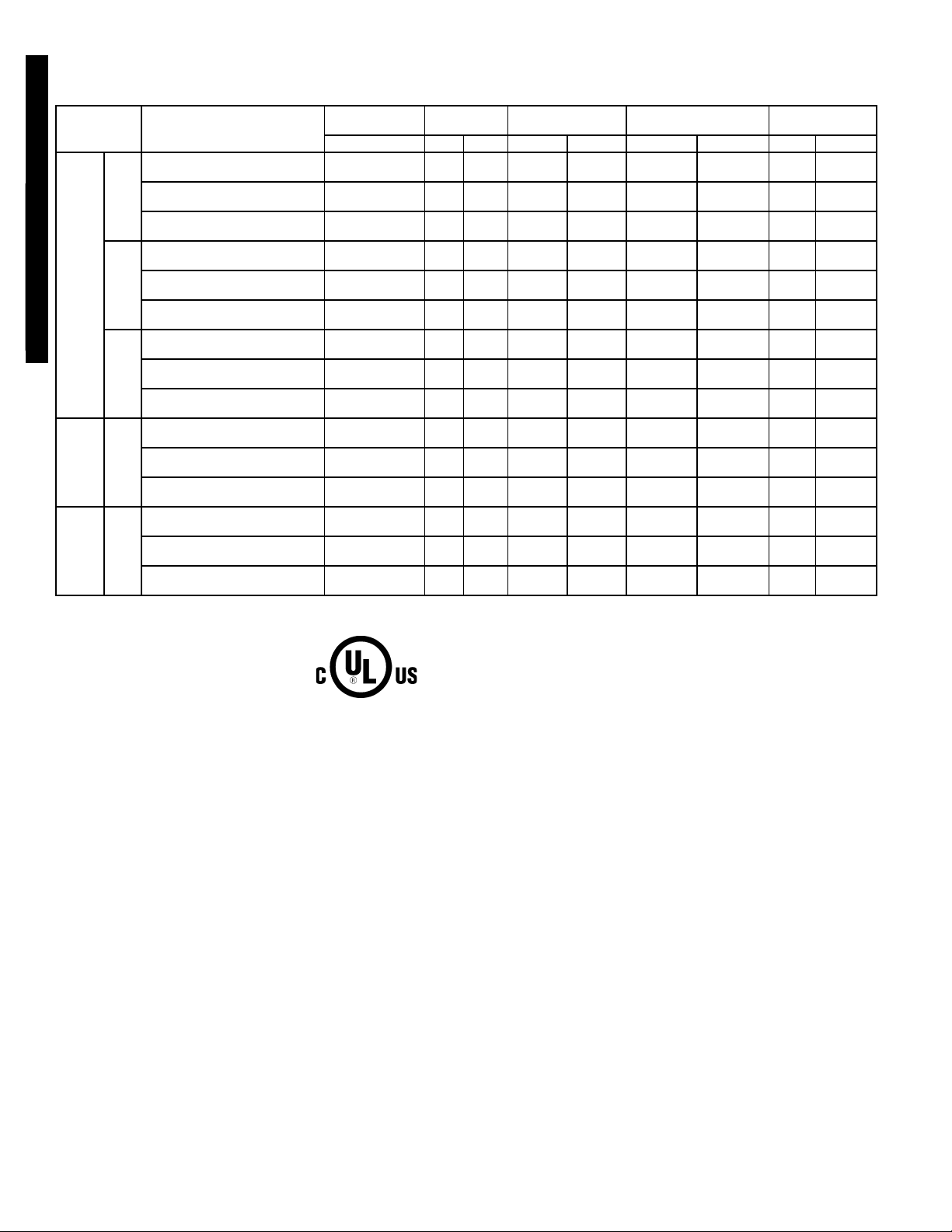
ELECTRICAL DATA
569D072-120, 576C120, 569F120 UNITS
UNIT
SIZE
072
569D
50TFQ004-012
569D072-120, 576C120, 569F120
576C 120
569F 120
FLA — Full Load Amps
LRA — Locked Rotor Amps
MCA — Minimum Circuit Amps
MOCP — Maximum Overcurrent Protection
NEC — National Electrical Code
RLA — Rated Load Amps
090
120
LEGEND *Units are suitable for use on electrical systems where voltage supplied
FACTORY-
INSTALLED
OPTION
NONE OR DISCONNECT
CONVENIENCE OUTLET 30.6 35
NONE OR DISCONNECT
CONVENIENCE OUTLET 15.0 20
NONE OR DISCONNECT
CONVENIENCE OUTLET 12.0 15
NONE OR DISCONNECT
CONVENIENCE OUTLET 39.8 60
NONE OR DISCONNECT
CONVENIENCE OUTLET 19.6 30
NONE OR DISCONNECT
CONVENIENCE OUTLET 15.5 20
NONE OR DISCONNECT
CONVENIENCE OUTLET 55.1 70
NONE OR DISCONNECT
CONVENIENCE OUTLET 25.1 30
NONE OR DISCONNECT
CONVENIENCE OUTLET 19.5 25
NONE OR DISCONNECT
CONVENIENCE OUTLET 52.8 70
NONE OR DISCONNECT
CONVENIENCE OUTLET 26.1 35
NONE OR DISCONNECT
CONVENIENCE OUTLET 20.3 30
NONE OR DISCONNECT
CONVENIENCE OUTLET 43.8 50
NONE OR DISCONNECT
CONVENIENCE OUTLET 21.6 25
NONE OR DISCONNECT
CONVENIENCE OUTLET 17.5 20
NOMINAL
VO LTAGE
V-P h- Hz MI N MAX RLA LRA FLA (ea) LRA (ea) MCA MOCP
208/230-3-60 187 254 19.2 146 0.9 1.6
460-3-60 418 506 9.6 73 0.4 0.9
575-3-60 523 632 7.7 58.4 0.4 0.9
208/230-3-60 187 254 25.6 190 1.5 3.1
460-3-60 418 506 12.8 95 0.7 1.9
575-3-60 523 632 10.2 76 0.7 1.9
208/230-3-60 187 254 37.8 239 1.5 3.1
460-3-60 418 506 17.2 125 0.7 1.9
575-3-60 523 632 13.4 80 0.7 1.9
208/230-3-60 187 254 36 198 1.5 3.1
460-3-60 418 506 18 99 0.7 1.9
575-3-60 523 632 14 79 0.7 1.9
208/230-3-60 187 254 16 125 1.5 3.1
460-3-60 418 506 8 66.5 0.7 1.9
575-3-60 523 632 6.4 50 0.7 1.9
VO LTAGE
RANGE*
COMPRESSOR
to the unit terminals is not below or above the listed limits.
NOTES:
1. The MCA and MOCP values are calculated in accordance with the
NEC, Article 440.
2. Motor RLA and LRA values are established in accordance with
Underwriters’ Laboratories (UL), Standard 1995.
3. The 575-v units are UL, Canada-listed only.
4. Convenience outlet is available as either a factory-installed option
or a field-installed accessory and is 115-v, 1 ph, 60 Hz.
FAN M OTO RS
(Qty 2)
POWER
SUPPLY
25.8 35
12.8 20
10.2 15
35.0 60
17.4 30
13.8 20
50.3 60
22.9 30
17.8 25
48.0 60
23.9 35
18.6 30
39.0 50
19.4 25
15.8 20
26
Page 27

APPLICATION DATA — 569D072-120, 576C090-120, 569F120
OPERATING LIMITS
Maximum Cooling Outdoor 115 F
Minimum Outdoor Ambient
Minimum Return-Air
Temperature
Maximum Return-Air
Temperature
Normal Acceptable Saturation
Suction Temperature Range
Maximum Discharge
Temperature
Minimum Discharge Superheat 60 F
NOTES:
1. Select air handler at no less than 300 cfm/ton (nominal condensing unit capacity).
2. Total combined draw of the field-supplied liquid line solenoid valve
and air handler fan contactor must not exceed 22 va. If the specified va must be exceeded, use a remote relay to control the load.
1. LIQUID LINE — For applications with liquid lift greater than
1
20 ft, use
liquid line where
/2-in. liquid line where3/8in.isshown;use5/8-in.
1
/2in. is shown. The maximum liquid lift is
60 ft.
MAXIMUM REFRIGERANT CHARGE
UNIT
SIZE
569D
072 17.3
090 34.2
120 34.2
576C 120 34.2
569F 120 (2) 17.1
2. REFRIGERANT PIPING — It is recommended that the
refrigerant piping for all commercial split systems include a
liquid line solenoid valve, a liquid line filter drier, and a sight
glass.
For refrigerant lines longer than 75 lineal ft, a liquid line
solenoid valve and a suction accumulator are required.
Refer to the Refrigerant Specialties table.
See Minimum Outdoor-Air
Operating Temperature
table at right.
55 F
95 F
25 to 55 F
275 F
R-22 (lb)
MINIMUM OUTDOOR-AIR OPERATING
TEMPERATURE
MINIMUM
UNIT
SIZE
COMPR
CAPACITY
COND
TEMP
(F)
OUTDOOR TEMP
(F)
With
Std
Motormaster
Control
072 100% 90 35
569D
576C 120*
090 100% 90 35
120 100% 90 35
100% 90 35
67% 80 35
–20
569F 120 100% 90 35
*Unit has one step of unloading.
REFRIGERANT PIPING SIZES
LINEAR LENGTH OF PIPING — FT
UNIT
SIZE
072
0903/811/
569D
1201/213/
576C 1201/213/
569F 120 (2)3/8(2) 11/8(2)3/8(2) 11/8(2)3/8(2) 11/8(2)3/8(2) 11/
L—Liquid Line S—Suction Line
NOTES:
1. Pipe sizes are based on a 2° F loss for liquid and suction lines.
2. Pipe sizes are based on the maximum linear length, shown for
each column, plus a 50% allowance for fittings.
3. Charge units with R-22 in accordance with unit installation
instructions.
0-25 25-50 50-75 75-100
Line Size (in. OD)
LSLSLSLS
3
/811/
8
8
8
8
3
/811/
1
/211/
1
/213/
1
/213/
8
8
8
8
3
/811/
1
/211/
1
/213/
1
/213/
8
8
8
8
3
/811/
1
/211/
1
/213/
1
/213/
LEGEND
569D072-120, 576C120, 569F120
50TFQ004-012
®
8
8
8
8
8
UNIT
LIQUID LINE
569D072
569D090
569D120
576C120
*Bushings required.
SIZE (in.)
3
/
8
3
/
8
1
/
2
1
/
2
1
/
2
3
/
8
REFRIGERANT SPECIALTIES PART NUMBERS
LIQUID LINE
SOLENOID VALVE (LLSV)
200RB5T3M AMG/24V AMI-1TT3 P502-8304S* S-7063S*
200RB5T3M AMG/24V AMI-1TT3 P502-8304S* S-7063S*
200RB5T4M AMG/24V AMI-1TT4 P502-8304S S-7063S*
200RB6T4M AMG/24V AMI-1TT4 P502-8307S* S-7063
200RB6T4M AMG/24V AMI-1TT4 P502-8307S* S-7063
200RB5T3M Qty 2 AMG/24V Qty 2 AMI-1TT3 Qty 2 P502-8304S* Qty 2 S-7061 Qty 2
LLSV
COIL
SIGHT
GLASS
FILTER
DRIER
SUCTION LINE
ACCUMULATOR
27
Page 28

WEATHERPROOF
FUSED DISCONNECT*
PER NEC
TYPICAL PIPING AND WIRING
50TFQ004-012
569D072-120, 576C120, 569F120
FIELD
SUPPLIED
POWER
POWER WIRES
INSULATED
VAPOR
LINE
CONTROL
WIRES
INDOOR
THERMOSTAT†
PITCH
CONDENSING
UNIT
FILTER
DRIER*
LIQUID
LINE
CONDENSATE DRAIN
POWER WIRES
FUSED DISCONNECT
PER NEC
TO OPEN SIGHT
DRAIN
MOISTURE
INDICATOR
SIGHT GLASS*
LLSV*
ELECTRIC
HEATER
ACCESSORY
524A
UNIT
LEGEND
LLSV — Liquid Line Solenoid Valve
NEC — National Electrical Code
TXV—Thermostatic Expansion Valve
*Field supplied.
†Accessory item.
NOTES:
1. All piping must follow standard refrigerant piping techniques. Refer to Carrier System
Design Manual for details.
2. All wiring must comply with the applicable local and national codes.
3. Wiring and piping shown are general points-of-connection guides only and are not
intended for, or to include all details for, a specific installation.
4. Liquid line solenoid valve (solenoid drop control) is recommended to prevent refrigerant migration to the compressor.
5. Internal factory-supplied TXVs not shown.
Rooftop Installation — 569D072-120, 576C120
28
Page 29

GUIDE SPECIFICATIONS — 569D072-120, 576C120
COMMERCIAL AIR-COOLED CONDENSING UNITS
HVAC GUIDE SPECIFICATIONS
SIZE RANGE: 6 TO 10 TONS, NOMINAL
BRYANT MODEL NUMBERS: 569D, SIZES 072-120
576C, SIZE 120
PART 1 — GENERAL
1.01 SYSTEM DESCRIPTION
Outdoor-mounted, air-cooled condensing unit suitable for
on-the-ground or rooftop installation. Unit shall consist of a
reciprocating air-conditioning compressor assembly
(576C) or scroll compressor (569D), an air-cooled coil,
propeller-type condenser fan, and a control box. Unit shall
discharge supply air upward as shown on contract drawings. Unit shall be used in a refrigeration circuit matched
with a packaged air-handling unit.
1.02 QUALITY ASSURANCE
A. Unit shall be rated in accordance with ARI latest
revisions.
B. Unit construction shall comply with ANSI/ASHRAE 15
safety code latest revision and comply with NEC.
C. Unit shall be constructed in accordance with UL 1995
standard and shall carry the UL and UL, Canada label.
D. Unit cabinet shall be capable of withstanding 500-hour
salt spray exposure per ASTM B117 (scribed specimen).
E. Air-cooled condenser coils for semi-hermetic compressor
units (576C) shall be leak tested at 150 psig and pressure
tested at 480 psig. Air-cooled condenser coils for scroll
compressor units (569D) shall be leak tested at 200 psig,
and pressure tested at 428 psig.
F. Unit shall be manufactured in a facility registered to
ISO 9001:2000 manufacturing quality standard.
1.03 DELIVERY, STORAGE, AND HANDLING
Unit shall be shipped as single package only, and shall be
stored and handled according to unit manufacturer’s
recommendations.
1.04 WARRANTY (FOR INCLUSION BY SPECIFYING
ENGINEER.)
PART 2 — PRODUCTS
2.01 EQUIPMENT
A. General:
Factory-assembled, single piece, air-cooled condensing
unit. Contained within the unit enclosure shall be all
factory wiring, piping, controls, compressor, holding
charge (R-22), and special features required prior to field
start-up.
B. Unit Cabinet:
1. Unit cabinet shall be constructed of galvanized steel,
bonderized and coated with a prepainted baked
enamel finish.
2. A heavy-gage roll-formed perimeter base rail with
forklift slots and lifting holes shall be provided to facilitate rigging.
C. Fans:
1. Condenser fans shall be direct driven, propeller-type,
discharging air vertically upward.
2. Fan blades shall be balanced.
3. Condenser fan discharge openings shall be
equipped with PVC coated steel wire safety guards.
4. Condenser fan and motor shaft shall be corrosion
resistant.
D. C o mpresso r :
1. Compressor shall be of the scroll type (569D) or
semi-hermetic reciprocating type (576C).
2. Compressors shall be mounted on vibration
isolators.
3. Compressors shall include overload protection.
4. Compressors shall be equipped with a crankcase
heater.
5. Compressor shall be equipped with internal high discharge temperature protection (569D072 and 120
only).
6. Compressor shall unload using suction cutoff unloading (576C120 only). Electric solenoid unloading
available as an accessory.
E. Condenser Coil:
1. Condenser coil shall be air-cooled and circuited for
integral subcooler.
2. Coil shall be constructed of aluminum fins (copper
fins optional) mechanically bonded to internally
grooved seamless copper tubes which are then
cleaned, dehydrated, and sealed.
F. Refrigeration Components:
Refrigeration circuit components shall include liquid line
service valve, suction line service valve, liquid filter drier,
a full charge of compressor oil, and a holding charge of
refrigerant. Unit 569D120 shall include an accumulator.
Units with semi-hermetic compressors (576C) shall have
oil-level sight glass and all units shall have crankcase
heater.
G. Controls and Safeties:
1. Minimum control functions shall include:
a. Control wire terminal blocks.
b. Compressor lockout on auto-reset safety until
reset from thermostat.
2. Minimum safety devices which are equipped with
automatic reset (after resetting first at thermostat),
shall include:
a. High discharge pressure cutout.
b. Low Pressure cutout.
c. High discharge temperature cutout (569D090
only).
H. Operating Characteristics:
1. The capacity of the condensing unit shall meet or
exceed Btuh at a suction temperature of ______ F.
The power consumption at full load shall not exceed
______ kW.
2. The combination of the condensing unit and the
evaporator or fan coil unit shall have a total net cooling capacity of ______ Btuh or greater at conditions
of ______ cfm entering-air temperature at the evaporator at ______ F wet bulb and ______ F dry bulb,
and air entering the condensing unit at ______ F.
3. The system shall have an EER of ______ Btuh/Watt
or greater at standard ARI conditions.
I. Electrical Requirements:
1. Nominal unit electrical characteristics shall be
______ v, 3-ph, 60 Hz. The unit shall be capable of
satisfactory operation within voltage limits of
______ v to ______ v.
2. Unit electrical power shall be single-point connection.
3. Unit control circuit shall contain a 24-v transformer
for unit control.
569D072-120, 576C120, 569F120
50TFQ004-012
29
Page 30

J. Special Features:
1. Low-Ambient Temperature Control Accessory:
2. Optional Condenser Coil Materials:
50TFQ004-012
569D072-120, 576C120, 569F120
GUIDE SPECIFICATIONS — 569D072-120, 576C120 (cont)
Low-ambient control shall be available as a factoryinstalled option or a field-installed accessory and
shall regulate speed of condenser-fan motor in
response to the saturated condensing temperature
of the unit. The control shall maintain correct condensing pressure at outdoor temperatures down to
–20 F (fan motor change required for 569D and
576C units).
a. Pre-Coated Aluminum-Fin Coils:
Shall have a durable epoxy-phenolic coating to
provide protection in mildly corrosive coastal environments. Coating shall be applied to the aluminum fin stock prior to the fin stamping process to
create an inert barrier between the aluminum
fin and copper tube. Epoxy-phenolic barrier shall
minimize galvanic action between dissimilar
metals.
b. E-Coated Aluminum-Fin Coils:
Shall have a flexible epoxy polymer coating uniformly applied to all coil surface areas without
material bridging between fins. Coating process
shall ensure complete coil encapsulation. Color
shall be high gloss black with gloss requirements
of 60° of 65-90% per ASTM D523-89. Uniform dry
film thickness from 0.8 to 1.2 mil on all surface
areas including fin edges. Superior hardness characteristics of 2H per ASTM D3363-92A and cross
hatch adhesion of 4B-5B per ASTM D3359-93.
Impact resistance shall be up to 160 in./lb (ASTM
D2794-93). Humidity and water immersion resistance shall be up to a minimum of 1000 and
250 hours respectively (ASTM-D2247-92 and
ASTM D870-92). Corrosion durability shall be confirmed through testing to no less than 1000 hours
salt spray per ASTM B117-90. Coil construction
shall be aluminum-fins mechanically bonded to
copper tubes.
3. Thermostat Control Accessory:
a. Commercial Electronic Thermostat with 7-day
timeclock, auto-changeover, multi-stage capability, and large LCD temperature display.
b. Commercial Electronic Non-programmable Ther-
mostat with auto-changeover, multi-stage capacity,
and large LCD display.
4. Hail Guard Accessory:
Hail guard package shall protect coils against dam-
age from hail and other flying debris.
5. Condenser Coil Grille Accessory:
Grille shall add decorative appearance to unit and
protect condenser coil after installation.
6. Electric Solenoid Unloader Accessory:
Electric unloader valve piston, coil, and hardware
shall be supplied to convert the pressure-operated
compressor unloader to electric unloading (576C120
only).
7. Unit-Mounted, Non-Fused Disconnect Switch:
Shall be factory-installed, internally mounted. NEC
and UL approved non-fused switch shall provide unit
power shutoff. Shall be accessible from outside the
unit and shall provide power off lockout capability.
Not to be used when rooftop electrical rating
exceeds 80 amperes.
8. Convenience Outlet:
Shall be factory-installed and internally mounted
with easily accessible 115-v female receptacle. Shall
include 15 amp GFI receptacle with independent
fuse protection. Voltage required to operate convenience outlet shall be provided by a factory-installed
step-down transformer. Shall be accessible from outside the unit.
30
Page 31

GUIDE SPECIFICATIONS — 569F120
COMMERCIAL AIR-COOLED CONDENSING UNITS
HVAC GUIDE SPECIFICATIONS
SIZE RANGE: 10 TONS, NOMINAL
BRYANT MODEL NUMBER: 569F, SIZE 120
PART 1 — GENERAL
1.01 SYSTEM DESCRIPTION
Outdoor-mounted, air-cooled condensing unit suitable for
on-the-ground or rooftop installation. Unit shall have
2 independent refrigeration circuits. Unit shall consist of
dual scroll compressors, air-cooled coils, propeller-type
condenser fans, and a control box. Unit shall discharge
supply air upward as shown on contract drawings. Unit
shall be used in a refrigeration circuit matched with a packaged air-handling unit.
1.02 QUALITY ASSURANCE
A. Unit shall be rated in accordance with ARI Standard 210/
240, latest revision.
B. Unit construction shall comply with ANSI/ASHRAE 15
safety code latest revision and comply with NEC.
C. Unit shall be constructed in accordance with UL 1995
standard and shall carry the UL and UL, Canada label.
D. Unit cabinet shall be capable of withstanding 500-hour
salt spray exposure per ASTM B117 (scribed specimen).
E. Air-cooled condenser coils shall be leak tested at
200 psig, and pressure tested at 428 psig.
F. UnitshallbemanufacturedinafacilityregisteredtoISO
9001:2000 manufacturing quality standard.
1.03 DELIVERY, STORAGE, AND HANDLING
Unit shall be shipped as single package only, and shall be
stored and handled according to unit manufacturer’s
recommendations.
1.04 WARRANTY (FOR INCLUSION BY SPECIFYING
ENGINEER.)
PART 2 — PRODUCTS
2.01 EQUIPMENT
A. General:
Factory-assembled, single piece, air-cooled condensing
unit. Contained within the unit enclosure shall be all
factory wiring, piping, controls, compressor, holding
charge (R-22), and special features required prior to field
start-up.
B. Unit Cabinet:
1. Unit cabinet shall be constructed of galvanized steel,
bonderized and coated with a prepainted baked
enamel finish.
2. A heavy-gage roll-formed perimeter base rail with
forklift slots and lifting holes shall be provided to facilitate rigging.
C. Fans:
1. Condenser fans shall be direct driven, propeller-type,
discharging air vertically upward.
2. Fan blades shall be balanced.
3. Condenser fan discharge openings shall be
equipped with PVC coated steel wire safety guards.
4. Condenser fan and motor shaft shall be corrosion
resistant.
D. C ompresso r :
1. Compressors shall be of the hermetic scroll type.
2. Compressors shall be mounted on vibration isolators.
3. Compressors shall include overload protection.
4. Compressors shall be equipped with a crankcase
heater.
5. Compressors shall be equipped with high discharge
temperature protection.
E. Condenser Coil:
1. Condenser coil shall be air-cooled and circuited for
integral subcooler.
2. Coil shall be constructed of aluminum fins (copper
fins optional) mechanically bonded to internally
grooved seamless copper tubes which are then
cleaned, dehydrated, and sealed.
F. Refrigeration Components:
Refrigeration circuit components shall include liquid
line service valve, suction line service valve, a full
charge of compressor oil, and a holding charge of
refrigerant.
G. Controls and Safeties:
1. Minimum control functions shall include:
a. Control wire terminal blocks.
b. Compressor lockout on auto-reset safety until
reset from thermostat.
2. Minimum safety devices which are equipped with
automatic reset (after resetting first at thermostat),
shall include:
a. High discharge pressure cutout.
b. Low pressure cutout.
H. Operating Characteristics:
1. The capacity of the condensing unit shall meet or
exceed _____ Btuh at a suction temperature of
_____ F. The power consumption at full load shall not
exceed _____ kW.
2. The combination of the condensing unit and the
evaporator or fan coil unit shall have a total net cooling capacity of _____ Btuh or greater at conditions of
_____ cfm entering-air temperature at the evaporator
at _____ F wet bulb and _____ F dry bulb, and air
entering the condensing unit at _____ F.
3. The system shall have an EER of _____ Btuh/ Watt
or greater at standard ARI conditions.
I. Electrical Requirements:
1. Nominal unit electrical characteristics shall be _____
v, 3-ph, 60 Hz. The unit shall be capable of satisfactory operation within voltage limits of _____ v to
_____ v.
2. Unit electrical power shall be single-point connection.
3. Unit control circuit shall contain a 24-v transformer
for unit control.
J. Special Features:
1. Low-Ambient Temperature Control:
A low-ambient temperature control shall be available
as a factory-installed option or as a field-installed
accessory. This low-ambient control shall regulate
speed of the condenser-fan motors in response to
the saturated condensing temperature of the unit.
The control shall maintain correct condensing pressure at outdoor temperatures down to –20 F.
2. Gage Panel Package:
Gage panel package shall include a suction and discharge pressure gage.
569D072-120, 576C120, 569F120
50TFQ004-012
31
Page 32

50TFQ004-012
569D072-120, 576C120, 569F120
GUIDE SPECIFICATIONS — 569F120 (cont)
3. Optional Condenser Coil Materials:
a. Pre-Coated Aluminum-Fin Coils:
Shall have a durable epoxy-phenolic coating to
provide protection in mildly corrosive coastal
environments. Coating shall be applied to the
aluminum fin stock prior to the fin stamping
process to create an inert barrier between the
aluminum fin and copper tube. Epoxy-phenolic
barrier shall minimize galvanic action between
dissimilar metals.
b. E-Coated Aluminum-Fin Coils:
Shall have a flexible epoxy polymer coating
uniformly applied to all coil surface areas without
material bridging between fins. Coating process
shall ensure complete coil encapsulation. Color
shall be high gloss black with gloss requirements
of 60° of 65 to 90% per ASTM D523-89. Uniform
dry film thickness from 0.8 to 1.2 mil on all surface
areas including fin edges. Superior hardness
characteristics of 2H per ASTM D3363-92A
and cross hatch adhesion of 4B-5B per ASTM
D3359-93. Impact resistance shall be up to
160 in./lb (ASTM D2794-93). Humidity and water
immersion resistance shall be up to a minimum
of 1000 and 250 hours respectively (ASTM
D2247-92 and ASTM D870-92). Corrosion durability shall be confirmed through testing to no less
than 1000 hours salt spray per ASTM B117-90.
Coil construction shall be aluminum fins mechanically bonded to copper tubes.
4. Thermostat Controls:
a. Programmable multi-stage thermostat with 7-day
clock, holiday scheduling, large backlit display,
remote sensor capability, and Title 24 compliance.
b. Commercial Electronic Thermostat with 7-day
timeclock, auto-changeover, multi-stage capability, and large LCD temperature display.
5. Hail Guard Package:
Hail guard package shall protect coils against dam-
age from hail and other flying debris.
6. Condenser Coil Grille:
Grille shall add decorative appearance to unit and
protect condenser coil after installation.
7. Unit-Mounted, Non-Fused Disconnect Switch:
Shall be factory-installed, internally mounted. NEC
and UL approved non-fused switch shall provide unit
power shutoff. Shall be accessible from outside the
unit and shall provide power off lockout capability.
8. Convenience Outlet:
Shall be factory-installed and internally mounted with
easily accessible 115-v female receptacle. Shall
include 15 amp GFI receptacle with independent
fuse protection. Voltage required to operate convenience outlet shall be provided by a factory-installed
step-down transformer. Shall be accessible from outside the unit.
32
Page 33

MODEL NUMBER NOMENCLATURE
566D E X 150 000
––
566D — Commercial Air-Cooled Condensing
Unit With Semi-Hermetic Compressor
566E — Dual Circuit Commercial Air-Cooled
Condensing Unit With Scroll Compressors
Voltage Designation
E — 460-3-60
P — 208/230-3-60
T — 575-3-60
Heating
X—None
*Contact your local representative for more details.
Quality Assurance
Certified to ISO 9001:2000
Factory-Installed Options*
Heating Capacity
000 — No Heat
Nominal Tons Cooling
150 — 12-1/2
180 — 15
240 — 20
566D/E150-240
50TFQ004-012
33
Page 34

PHYSICAL DATA
566D150-240 UNITS
50TFQ004-012
566D/E150-240
UNIT 566D150 566D180 566D240
NOMINAL CAPACITY (tons) 12
1
/
2
15 20
OPERATING WEIGHTS (lb)
Aluminum-Fin Coil (Standard) 779 789 929
Copper-Fin Coil (Optional) 919 929 1040
REFRIGERANT TYPE* R-22
Operating Charge, Typical (lb)† 23 23 28
Shipping Charge (lb) 3.1 3.1 3.1
COMPRESSOR Reciprocating, Semi-Hermetic
Qty...Model 1...06DD328 1...06DD537 1...06E4250
No. Cylinders 664
Speed (rpm) 1750 1750 1750
Oil Charge (pt) 10 10 15.5
Capacity Steps
Accessory 33**, 66, 100 33**, 66, 100 —
Standard 66, 100 66, 100 50, 100
Unloader Setting (psig)
Load 70 ± 1
Unload 60 ± 2
Crankcase Heater Watts 125
CONDENSER FANS Axial Flow, Direct Drive
Qty...Rpm 2...1075
Diameter (in.) 26
Nominal Hp
Nominal Airflow (cfm, total) 11,000
1
/
2
Watts (total) 1460
CONDENSER COIL Copper Tubes, Aluminum Fins
Rows...Fins/in. 3...15 3...15 3...15
Face Area (sqft) 29.2 29.2 29.2
Storage Capacity (lb)†† 48 48 38
CONTROLS
Pressurestat (psig)
High Pressure
Cutout 395 ± 10
Cut-in 295 ± 20
Low Pressure
Cutout 27 ± 4
Cut-in 67 ± 7
FAN CYCLING CONTROLS
Operating Pressure (psig)
No. 2 Fan, Close 255 ± 10
Open 160 ± 10
PRESSURE RELIEF
Location Liquid Line
Temperature (F) 200
PIPING CONNECTIONS (in. ODM)
Suction 13/
Liquid
Hot Gas Stub
8
13/
8
5
/
8
3
/
8
15/
8
*Unit is factory-supplied with holding charge only.
†Typical operating charge with 25 ft of interconnecting piping. Operating charge is approximate for maximum system
capacity.
**Indicates capacity step (%) with electric unloader accessory.
††Storage capacity is measured at liquid saturated temperatures of 120 F.
34
Page 35

PHYSICAL DATA (cont)
566E150-240 UNITS
UNIT 566E150 566E180 566E240
NOMINAL CAPACITY (tons) 12
1
/
2
15 20
OPERATING WEIGHTS (lb)
Aluminum-Fin Coil (Standard) 676 740 764
Copper-Fin Coil (Optional) 822 886 904
REFRIGERANT TYPE* R-22
Operating Charge, Typical (lb)† 23 23 28
Shipping Charge (lb) 3.1 3.1 3.1
COMPRESSOR Scroll
Qty...Model 2...ZR72 2...ZR94 2...ZR125
Speed (rpm) 3500 3500 3500
Oil Charge (oz) 60 (ea) 85 (ea) 110 (ea)
Crankcase Heater Watts 70
CONDENSER FANS
Qty...Rpm 2...1075
Diameter (in.) 26
Nominal Hp
Nominal Airflow (cfm, total) 11,000
1
/
2
Watts (total) 1460
CONDENSER COIL
Rows...Fins/in. 3...15
Face Area (sqft) 29.2
Storage Capacity (lb)** 48
CONTROLS
Pressurestat (psig)
High Pressure
Cutout 426 ± 7
Cut-in 320 ± 20
Low Pressure
Cutout 27 ± 4
Cut-in 67 ± 7
FAN CYCLING CONTROLS
Operating Pressure (psig)
No. 2 Fan,Close 255 ± 10
Open 160 ± 10
PRESSURE RELIEF
Location Liquid Line
Temperature (F) 200
PIPING CONNECTIONS (in. ODM)
Suction (2) 13/
Liquid (2)1/
Hot Gas Stub
*Unit is factory-supplied with holding charge only.
†Typical operating charge with 25 ft of interconnecting piping. Operating charge is approximate for
8
2
3
/
8
maximum system capacity.
**Storage capacity is measured at liquid saturated temperatures of 120 F.
566D/E150-240
50TFQ004-012
35
Page 36

NOTES:
1. Service clearances are as follows:
Side (compressor) — 3
Side (opposite compressor) — 3 ft
Ends—2ft
Top—5ft
2. See page 38 for corner weights and
unit center of gravity.
1
/2ft
DIMENSIONS
50TFQ004-012
566D/E150-240
566D150-240
36
Page 37

NOTES:
1. Service clearances are as follows:
Side (compressor) — 3
Side (opposite compressor) — 3 ft (914 mm)
Ends — 2 ft (610 mm)
Top — 5 ft (1524 mm)
2. See page 38 for corner weights and unit
center of gravity.
1
/2ft (1067 mm)
DIMENSIONS (cont)
566D/E150-240
50TFQ004-012
566E150-240
37
Page 38

DIMENSIONS (cont)
566D150-240
50TFQ004-012
566D/E150-240
UNIT
566D
150 779 70 177 68 100 261 103
180 789 70 180 69 101 265 104
240 900 84 234 82 108 310 111
Standard
Weight
(lb)
UNIT
566D
150 38 16
180 38 16
240 37 17
ALUMINUM COIL
Operational Weight Points (lb)
ABCD E F
CENTER OF GRAVITY (in.)
Aluminum Coil
X Y
566E150-240
UNIT
566E
150 676 84 168 72 78 183 91
180 740 86 186 71 82 216 99
240 764 87 192 72 85 226 102
Standard
Weight
(lb)
ALUMINUM COIL
Operational Weight Points (lb)
ABCDE F
UNIT
566E
150 35 19
180 35 18
240 35 18
NOTES:
1. Corner weights are approximate.
2. Actual support weights depend on level of unit and evenness of support posts.
3. Total weights represent approximate unit weights without shipping package.
4. Bottom or top skid is NOT included in the weights.
CENTER OF GRAVITY (in.)
Aluminum Coil
X Y
566D150-240, 566E150-240
38
Page 39

566D150
SST (F)
TC 101.0 97.6 90.0 86.0 82.2 74.7
25
kW 8.56 8.90 9.55 9.85 10.20 10.70
SDT 94.6 99.4 109.0 114.0 119.0 129.0
TC 118.0 113.0 105.0 101.0 96.7 88.5
30
kW 8.80 9.17 9.90 10.20 10.60 11.20
SDT 96.6 101.0 111.0 116.0 121.0 131.0
TC 134.0 129.0 120.0 116.0 111.0 102.0
35
kW 9.03 9.44 10.20 10.60 11.00 11.70
SDT 98.6 103.0 113.0 117.0 122.0 132.0
TC 150.0 145.0 135.0 130.0 126.0 116.0
40
kW 9.26 9.71 10.60 11.00 11.40 12.20
SDT 101.0 105.0 115.0 119.0 124.0 134.0
TC 166.0 161.0 150.0 145.0 140.0 130.0
45
kW 9.50 9.98 10.90 11.40 11.80 12.70
SDT 103.0 107.0 116.0 121.0 126.0 135.0
TC 182.0 177.0 166.0 160.0 155.0 144.0
50
kW 9.73 10.30 11.30 11.70 12.20 13.10
SDT 105.0 109.0 118.0 123.0 127.0 136.0
566D180
SST (F)
TC 139.0 134.0 126.0 121.0 117.0 108.0
25
kW 12.30 12.70 13.60 14.00 14.40 15.10
SDT 99.5 104.0 114.0 118.0 123.0 133.0
TC 159.0 154.0 144.0 139.0 134.0 125.0
30
kW 12.90 13.40 14.30 14.70 15.20 16.00
SDT 102.0 107.0 116.0 121.0 125.0 135.0
TC 179.0 173.0 163.0 157.0 152.0 142.0
35
kW 13.50 14.00 15.00 15.50 16.00 16.90
SDT 105.0 109.0 119.0 123.0 128.0 137.0
TC 198.0 192.0 181.0 175.0 170.0 158.0
40
kW 14.00 14.60 15.70 16.30 16.80 17.80
SDT 108.0 112.0 121.0 125.0 130.0 139.0
TC 218.0 212.0 199.0 193.0 187.0 175.0
45
kW 14.60 15.20 16.50 17.00 17.60 18.70
SDT 110.0 115.0 124.0 128.0 132.0 141.0
TC 237.0 231.0 218.0 211.0 205.0 192.0
50
kW 15.20 15.90 17.20 17.80 18.40 19.60
SDT 113.0 117.0 126.0 130.0 135.0 144.0
566D240
SST (F)
TC 175.0 169.0 157.0 151.0 145.0 134.0
25
kW 16.30 16.80 17.70 18.20 18.60 19.40
SDT 104.0 108.0 117.0 122.0 126.0 135.0
TC 200.0 193.0 180.0 173.0 166.0 154.0
30
kW 17.20 17.80 18.80 19.30 19.80 20.70
SDT 107.0 111.0 120.0 125.0 129.0 138.0
TC 224.0 217.0 202.0 195.0 188.0 175.0
35
kW 18.20 18.80 19.90 20.50 21.00 22.00
SDT 110.0 115.0 123.0 128.0 132.0 141.0
TC 249.0 241.0 225.0 218.0 210.0 195.0
40
kW 19.10 19.80 21.00 21.60 22.20 23.30
SDT 114.0 118.0 126.0 131.0 135.0 144.0
TC 273.0 265.0 248.0 240.0 232.0 216.0
45
kW 20.10 20.80 22.10 22.70 23.40 24.60
SDT 117.0 121.0 129.0 134.0 138.0 146.0
TC 297.0 289.0 271.0 262.0 253.0 236.0
50
kW 21.00 21.80 23.20 23.90 24.60 25.90
SDT 120.0 124.0 132.0 137.0 141.0 149.0
kW—Compressor Power
SDT — Saturated Discharge Temperature at Compressor (F)
SST — Saturated Suction Temperature (F)
TC — Gross Cooling Capacity (1000 Btuh)
Air Temperature Entering Condenser (F)
80 85 95 100 105 115
Air Temperature Entering Condenser (F)
80 85 95 100 105 115
Air Temperature Entering Condenser (F)
80 85 95 100 105 115
LEGEND
PERFORMANCE DATA
CONDENSING UNIT RATINGS
566E150
SST (F)
TC 102.0 99.1 93.2 90.3 87.3 81.1
20
kW 9.04 9.58 10.80 11.40 12.10 13.50
SDT 103.0 108.0 118.0 123.0 128.0 138.0
TC 114.0 111.0 105.0 102.0 98.8 92.2
25
kW 9.09 9.64 10.90 11.50 12.20 13.60
SDT 103.0 108.0 118.0 123.0 128.0 138.0
TC 127.0 124.0 117.0 114.0 110.0 103.0
30
kW 9.14 9.70 10.90 11.50 12.20 13.70
SDT 103.0 108.0 118.0 123.0 128.0 138.0
TC 140.0 137.0 130.0 126.0 123.0 115.0
35
kW 9.19 9.75 11.00 11.60 12.30 13.70
SDT 103.0 108.0 118.0 123.0 128.0 138.0
TC 155.0 151.0 144.0 140.0 136.0 128.0
40
kW 9.26 9.81 11.00 11.70 12.30 13.80
SDT 103.0 108.0 118.0 123.0 128.0 138.0
TC 170.0 166.0 158.0 154.0 150.0 141.0
45
kW 9.37 9.90 11.10 11.70 12.40 13.90
SDT 103.0 108.0 118.0 123.0 128.0 138.0
TC 186.0 182.0 173.0 169.0 164.0 155.0
50
kW 9.55 10.10 11.30 11.90 12.60 14.00
SDT 104.0 109.0 119.0 124.0 129.0 139.0
566E180
SST (F)
TC 141.0 137.0 129.0 124.0 120.0 110.0
20
kW 12.01 12.60 13.70 14.30 14.90 16.10
SDT 101.0 105.0 115.0 120.0 125.0 135.0
TC 156.0 152.0 143.0 138.0 133.0 123.0
25
kW 12.40 12.90 14.00 14.60 15.20 16.40
SDT 102.0 107.0 116.0 121.0 126.0 136.0
TC 171.0 166.0 157.0 152.0 147.0 136.0
30
kW 12.70 13.20 14.30 14.90 15.50 16.70
SDT 104.0 108.0 118.0 123.0 127.0 137.0
TC 187.0 182.0 172.0 166.0 161.0 150.0
35
kW 13.10 13.60 14.70 15.30 15.90 17.10
SDT 105.0 110.0 119.0 12.04 129.0 138.0
TC 203.0 198.0 187.0 181.0 176.0 164.0
40
kW 13.50 14.00 15.10 15.70 16.30 17.50
SDT 107.0 112.0 121.0 126.0 130.0 140.0
TC 221.0 215.0 204.0 198.0 192.0 179.0
45
kW 13.90 14.50 15.60 16.10 16.70 17.90
SDT 109.0 114.0 123.0 127.0 132.0 141.0
TC 239.0 233.0 221.0 215.0 208.0 195.0
50
kW 14.40 14.90 16.10 16.70 17.20 18.40
SDT 111.0 116.0 125.0 129.0 134.0 143.0
566E240
SST (F)
TC 184.0 179.0 170.0 165.0 160.0 148.0
20
kW 16.20 17.00 18.50 19.40 20.20 21.70
SDT 105.0 110.0 119.0 124.0 129.0 139.0
TC 202.0 197.0 186.0 181.0 176.0 163.0
25
kW 16.80 17.50 19.00 19.80 20.60 22.20
SDT 107.0 112.0 121.0 126.0 131.0 140.0
TC 220.0 214.0 203.0 197.0 191.0 179.0
30
kW 17.30 18.00 19.50 20.30 21.10 22.70
SDT 109.0 113.0 123.0 127.0 132.0 141.0
TC 239.0 233.0 220.0 214.0 208.0 194.0
35
kW 18.00 18.60 20.10 20.80 21.60 23.20
SDT 111.0 116.0 125.0 129.0 134.0 143.0
TC 259.0 253.0 239.0 232.0 225.0 211.0
40
kW 18.70 19.30 20.70 21.50 22.20 23.80
SDT 113.0 118.0 127.0 131.0 136.0 145.0
TC 280.0 273.0 259.0 252.0 244.0 229.0
45
kW 19.40 20.10 21.50 22.20 22.90 24.50
SDT 116.0 120.0 129.0 134.0 138.0 147.0
TC 302.0 295.0 280.0 272.0 264.0 247.0
50
kW 20.20 20.90 22.30 23.00 23.70 25.20
SDT 118.0 123.0 132.0 136.0 140.0 149.0
Air Temperature Entering Condenser (F)
80 85 95 100 105 115
Air Temperature Entering Condenser (F)
80 85 95 100 105 115
Air Temperature Entering Condenser (F)
80 85 95 100 105 115
566D/E150-240
50TFQ004-012
39
Page 40

PERFORMANCE DATA (cont)
566D150/524A-C150 WITH HIGH CAPACITY 4-ROW COIL
Temp (F)
Air Entering
Condenser
(Edb)
TC 133.0 139.0 151.0 165.0 146.0 147.0 158.0 172.0 154.0 154.0 163.0 177.0
80
SHC 133.0 123.0 103.0 83.1 146.0 142.0 119.0 92.7 154.0 154.0 133.0 101.0
kW 9.00 9.07 9.27 9.48 9.18 9.20 9.38 9.59 9.32 9.32 9.45 9.66
TC 131.0 136.0 148.0 161.0 143.0 144.0 155.0 169.0 152.0 151.0 160.0 173.0
85
SHC 131.0 122.0 102.0 81.9 143.0 140.0 117.0 91.3 152.0 151.0 131.0 100.0
kW 9.44 9.54 9.75 9.99 9.66 9.69 9.88 10.10 9.82 9.81 9.96 10.20
TC 126.0 130.0 142.0 155.0 138.0 138.0 148.0 161.0 146.0 146.0 153.0 165.0
95
SHC 126.0 119.0 99.5 79.3 138.0 137.0 115.0 88.8 146.0 146.0 128.0 97.5
kW 10.40 10.50 10.70 11.00 10.60 10.60 10.90 11.20 10.80 10.80 11.00 11.30
100
105
115
TC 123.0 127.0 138.0 151.0 135.0 135.0 145.0 157.0 143.0 143.0 149.0 161.0
SHC 123.0 117.0 98.2 78.0 135.0 134.0 113.0 87.5 143.0 143.0 127.0 96.2
kW 10.80 10.90 11.20 11.50 11.10 11.10 11.30 11.70 11.30 11.30 11.50 11.80
TC 121.0 124.0 135.0 148.0 132.0 132.0 141.0 154.0 140.0 140.0 145.0 157.0
SHC 121.0 116.0 96.8 76.8 132.0 132.0 112.0 86.1 140.0 140.0 125.0 94.8
kW 11.30 11.40 11.70 12.00 11.60 11.60 11.80 12.20 11.80 11.80 12.00 12.30
TC 116.0 118.0 129.0 141.0 127.0 127.0 134.0 146.0 134.0 134.0 138.0 149.0
SHC 116.0 113.0 94.1 74.2 127.0 127.0 109.0 83.5 134.0 134.0 122.0 92.2
kW 12.20 12.30 12.60 13.00 12.50 12.50 12.80 13.20 12.80 12.80 12.90 13.30
57 62 67 72 57 62 67 72 57 62 67 72
3750 5000 6250
COMBINATION RATINGS
UNIT 566D150
Evaporator Air — Cfm
Evaporator Air — Ewb (F)
566D150/524A-B150 WITH STANDARD 3-ROW COIL
Temp (F)
Air Entering
Condenser
(Edb)
TC 127.0 134.0 146.0 160.0 140.0 142.0 153.0 167.0 148.0 148.0 158.0 172.0
80
SHC 127.0 118.0 99.4 80.2 140.0 136.0 114.0 89.0 148.0 148.0 126.0 96.9
kW 8.93 9.01 9.19 9.40 9.09 9.12 9.31 9.51 9.22 9.22 9.37 9.58
TC 125.0 131.0 143.0 156.0 137.0 139.0 150.0 163.0 145.0 145.0 154.0 168.0
85
SHC 125.0 117.0 98.2 78.9 137.0 134.0 112.0 87.6 145.0 145.0 125.0 95.6
kW 9.37 9.45 9.67 9.90 9.55 9.58 9.79 10.00 9.70 9.71 9.87 10.10
TC 121.0 125.0 137.0 150.0 132.0 133.0 143.0 156.0 140.0 140.0 147.0 160.0
95
SHC 121.0 114.0 95.6 76.4 132.0 130.0 110.0 85.1 140.0 140.0 122.0 93.0
50TFQ004-012
566D/E150-240
100
105
115
Edb — Entering Dry Bulb
Ewb — Entering Wet Bulb
kW—Compressor Motor Power Input
SHC — Sensible Heat Capacity (1000 Btuh) Gross
TC — Total Capacity (1000 Btuh) Gross
kW 10.30 10.30 10.60 10.90 10.50 10.50 10.70 11.00 10.70 10.70 10.80 11.10
TC 118.0 122.0 134.0 146.0 129.0 130.0 140.0 152.0 137.0 137.0 144.0 156.0
SHC 118.0 112.0 94.3 75.2 129.0 128.0 108.0 83.8 137.0 137.0 121.0 91.7
kW 10.70 10.80 11.10 11.40 11.00 11.00 11.20 11.60 11.20 11.20 11.30 11.70
TC 116.0 119.0 131.0 143.0 127.0 127.0 136.0 149.0 134.0 134.0 140.0 153.0
SHC 116.0 111.0 92.9 73.9 127.0 126.0 107.0 82.5 134.0 134.0 119.0 90.4
kW 11.20 11.20 11.50 11.90 11.40 11.40 11.70 12.10 11.60 11.60 11.80 12.20
TC 111.0 113.0 124.0 136.0 121.0 121.0 129.0 141.0 128.0 128.0 133.0 145.0
SHC 111.0 108.0 90.3 71.4 121.0 121.0 104.0 79.9 128.0 128.0 116.0 87.8
kW 12.00 12.10 12.50 12.90 12.40 12.40 12.60 13.10 12.60 12.60 12.80 13.20
57 62 67 72 57 62 67 72 57 62 67 72
LEGEND
3750 5000 6250
Evaporator Air — Cfm
Evaporator Air — Ewb (F)
40
Page 41

PERFORMANCE DATA (cont)
COMBINATION RATINGS (cont)
566D150/524A-C180 WITH HIGH CAPACITY 4-ROW COIL
Temp (F)
Air Entering
Condenser
(Edb)
TC 142.0 145.0 157.0 171.0 154.0 154.0 164.0 178.0 163.0 163.0 168.0 182.0
80
SHC 142.0 136.0 114.0 89.6 154.0 154.0 131.0 100.0 163.0 163.0 146.0 110.0
kW 9.13 9.17 9.37 9.57 9.31 9.32 9.47 9.66 9.44 9.45 9.53 9.72
TC 140.0 142.0 154.0 168.0 151.0 151.0 160.0 174.0 160.0 160.0 165.0 178.0
85
SHC 140.0 134.0 112.0 88.3 151.0 151.0 129.0 99.1 160.0 160.0 145.0 109.0
kW 9.60 9.65 9.86 10.10 9.81 9.81 9.97 10.20 9.96 9.96 10.00 10.30
TC 134.0 136.0 147.0 160.0 146.0 146.0 153.0 166.0 153.0 153.0 157.0 170.0
95
SHC 134.0 131.0 109.0 85.7 146.0 146.0 127.0 96.4 153.0 153.0 142.0 106.0
kW 10.50 10.60 10.80 11.20 10.80 10.80 11.00 11.30 11.00 11.00 11.10 11.40
100
105
115
TC 132.0 133.0 144.0 157.0 143.0 143.0 150.0 162.0 150.0 150.0 154.0 166.0
SHC 132.0 129.0 108.0 84.4 143.0 143.0 125.0 95.1 150.0 150.0 140.0 105.0
kW 11.00 11.10 11.30 11.70 11.30 11.30 11.50 11.80 11.50 11.50 11.60 11.90
TC 129.0 130.0 140.0 153.0 140.0 140.0 146.0 158.0 147.0 147.0 150.0 162.0
SHC 129.0 127.0 107.0 83.1 140.0 140.0 124.0 93.8 147.0 147.0 138.0 104.0
kW 11.50 11.50 11.80 12.20 11.80 11.80 12.00 12.30 12.00 12.00 12.10 12.40
TC 124.0 124.0 133.0 146.0 134.0 134.0 139.0 150.0 140.0 140.0 142.0 153.0
SHC 124.0 123.0 104.0 80.5 134.0 134.0 121.0 91.0 140.0 140.0 135.0 101.0
kW 12.40 12.50 12.80 13.20 12.80 12.80 13.00 13.40 13.00 13.00 13.10 13.50
57 62 67 72 57 62 67 72 57 62 67 72
4500 6000 7500
UNIT 566D150 (cont)
Evaporator Air — Cfm
Evaporator Air — Ewb (F)
566D150/524A-B180 WITH STANDARD 3-ROW COIL
Temp (F)
Air Entering
Condenser
(Edb)
TC 140.0 144.0 156.0 170.0 152.0 152.0 162.0 176.0 160.0 160.0 167.0 181.0
80
SHC 140.0 134.0 112.0 88.3 152.0 152.0 128.0 98.7 160.0 160.0 143.0 108.0
kW 9.09 9.14 9.34 9.55 9.28 9.28 9.44 9.65 9.41 9.41 9.51 9.71
TC 137.0 140.0 152.0 166.0 149.0 149.0 159.0 172.0 157.0 157.0 163.0 176.0
85
SHC 137.0 132.0 110.0 87.0 149.0 149.0 127.0 97.3 157.0 157.0 142.0 107.0
kW 9.56 9.61 9.84 10.10 9.78 9.77 9.94 10.20 9.92 9.92 10.00 10.20
TC 132.0 134.0 146.0 159.0 143.0 143.0 151.0 165.0 151.0 151.0 155.0 168.0
95
SHC 132.0 129.0 107.0 84.4 143.0 143.0 124.0 94.6 151.0 151.0 138.0 104.0
kW 10.50 10.50 10.80 11.10 10.70 10.70 10.90 11.20 10.90 10.90 11.00 11.30
100
105
115
Edb — Entering Dry Bulb
Ewb — Entering Wet Bulb
kW—Compressor Motor Power Input
SHC — Sensible Heat Capacity (1000 Btuh) Gross
TC — Total Capacity (1000 Btuh) Gross
TC 130.0 131.0 142.0 155.0 140.0 140.0 148.0 161.0 148.0 148.0 152.0 164.0
SHC 130.0 127.0 106.0 83.1 140.0 140.0 123.0 93.3 148.0 148.0 137.0 103.0
kW 11.00 11.00 11.30 11.60 11.30 11.20 11.40 11.80 11.40 11.40 11.50 11.80
TC 127.0 128.0 139.0 151.0 137.0 137.0 144.0 157.0 145.0 145.0 148.0 160.0
SHC 127.0 125.0 105.0 81.7 137.0 137.0 12.01 91.9 145.0 145.0 135.0 101.0
kW 11.40 11.50 11.80 12.10 11.70 11.70 11.90 12.30 11.90 11.90 12.00 12.40
TC 121.0 122.0 131.0 144.0 131.0 131.0 136.0 148.0 138.0 138.0 140.0 152.0
SHC 121.0 121.0 102.0 79.0 131.0 131.0 118.0 89.2 138.0 138.0 132.0 98.7
kW 12.40 12.40 12.70 13.10 12.70 12.70 12.90 13.30 12.90 12.90 13.00 13.40
57 62 67 72 57 62 67 72 57 62 67 72
LEGEND
4500 6000 7500
Evaporator Air — Cfm
Evaporator Air — Ewb (F)
566D/E150-240
50TFQ004-012
41
Page 42

PERFORMANCE DATA (cont)
COMBINATION RATINGS (cont)
566D180/524A-C180 WITH HIGH-CAPACITY 4-ROW COIL
Temp (F)
Air Entering
Condenser
(Edb)
TC 167.0 177.0 192.0 209.0 183.0 187.0 202.0 219.0 194.0 195.0 208.0 225.0
80
SHC 167.0 152.0 128.0 104.0 183.0 175.0 146.0 115.0 194.0 193.0 163.0 125.0
kW 13.10 13.40 13.90 14.40 13.60 13.70 14.10 14.70 13.90 13.90 14.30 14.80
TC 165.0 174.0 189.0 205.0 180.0 184.0 198.0 214.0 191.0 192.0 204.0 220.0
85
SHC 165.0 150.0 127.0 102.0 180.0 174.0 145.0 113.0 191.0 191.0 161.0 124.0
kW 13.70 14.00 14.50 15.00 14.20 14.30 14.80 15.30 14.60 14.60 15.00 15.50
TC 160.0 167.0 182.0 197.0 174.0 177.0 190.0 206.0 185.0 185.0 196.0 211.0
95
SHC 160.0 147.0 123.0 99.3 174.0 170.0 141.0 110.0 185.0 185.0 158.0 120.0
kW 14.90 15.20 15.70 16.40 15.50 15.60 16.10 16.70 15.90 15.90 16.30 16.90
100
105
115
TC 157.0 164.0 178.0 193.0 171.0 173.0 186.0 202.0 181.0 181.0 191.0 207.0
SHC 157.0 145.0 122.0 97.8 171.0 168.0 140.0 109.0 181.0 181.0 156.0 119.0
kW 15.50 15.80 16.40 17.00 16.10 16.20 16.70 17.40 16.50 16.50 17.00 17.60
TC 154.0 160.0 174.0 189.0 168.0 169.0 182.0 197.0 178.0 178.0 187.0 202.0
SHC 154.0 144.0 120.0 96.3 168.0 165.0 138.0 107.0 178.0 178.0 154.0 117.0
kW 16.00 16.30 17.00 17.70 16.70 16.80 17.40 18.10 17.20 17.20 17.60 18.30
TC 148.0 153.0 166.0 181.0 162.0 162.0 174.0 188.0 171.0 171.0 178.0 193.0
SHC 148.0 140.0 117.0 93.2 162.0 161.0 135.0 104.0 171.0 171.0 151.0 114.0
kW 17.30 17.50 18.20 19.00 18.00 18.00 18.60 19.40 18.50 18.50 18.90 19.70
57 62 67 72 57 62 67 72 57 62 67 72
4500 6000 7500
UNIT 566D180
Evaporator Air — Cfm
Evaporator Air — Ewb (F)
566D180/524A-B180 WITH STANDARD 3-ROW COIL
Temp (F)
Air Entering
Condenser
(Edb)
TC 165.0 175.0 190.0 207.0 180.0 185.0 200.0 217.0 191.0 193.0 206.0 223.0
80
SHC 165.0 149.0 126.0 102.0 180.0 172.0 143.0 113.0 191.0 190.0 159.0 123.0
kW 13.00 13.30 13.80 14.30 13.50 13.60 14.10 14.60 13.80 13.90 14.30 14.80
TC 162.0 171.0 187.0 203.0 177.0 181.0 196.0 213.0 188.0 189.0 202.0 218.0
85
SHC 162.0 148.0 125.0 101.0 177.0 170.0 142.0 112.0 188.0 187.0 158.0 121.0
kW 13.60 13.90 14.40 15.00 14.10 14.20 14.70 15.30 14.50 14.50 14.90 15.50
TC 157.0 165.0 179.0 195.0 171.0 174.0 188.0 204.0 182.0 182.0 193.0 209.0
95
SHC 157.0 144.0 121.0 97.9 171.0 166.0 139.0 108.0 182.0 181.0 154.0 118.0
50TFQ004-012
566D/E150-240
100
105
115
Edb — Entering Dry Bulb
Ewb — Entering Wet Bulb
kW—Compressor Motor Power Input
SHC — Sensible Heat Capacity (1000 Btuh) Gross
TC — Total Capacity (1000 Btuh) Gross
kW 14.80 15.10 15.70 16.30 15.30 15.50 16.00 16.60 15.80 15.80 16.20 16.90
TC 154.0 161.0 176.0 191.0 168.0 170.0 184.0 199.0 178.0 178.0 189.0 205.0
SHC 154.0 143.0 120.0 96.3 168.0 164.0 137.0 107.0 178.0 178.0 153.0 117.0
kW 15.30 15.70 16.30 17.00 16.00 16.10 16.70 17.30 16.40 16.40 16.90 17.50
TC 151.0 158.0 172.0 187.0 165.0 167.0 180.0 195.0 175.0 175.0 185.0 200.0
SHC 151.0 141.0 118.0 94.8 165.0 162.0 135.0 105.0 175.0 175.0 151.0 115.0
kW 15.90 16.20 16.90 17.60 16.60 16.70 17.30 18.00 17.00 17.00 17.50 18.20
TC 146.0 151.0 164.0 179.0 159.0 160.0 171.0 186.0 168.0 168.0 176.0 191.0
SHC 146.0 137.0 115.0 91.7 159.0 157.0 132.0 102.0 168.0 168.0 147.0 112.0
kW 17.10 17.40 18.10 18.90 17.80 17.90 18.50 19.30 18.30 18.30 18.80 19.50
57 62 67 72 57 62 67 72 57 62 67 72
LEGEND
4500 6000 7500
Evaporator Air — Cfm
Evaporator Air — Ewb (F)
42
Page 43

PERFORMANCE DATA (cont)
COMBINATION RATINGS (cont)
566D180/524A-C240 WITH HIGH-CAPACITY 4-ROW COIL
Temp (F)
Air Entering
Condenser
(Edb)
TC 196.0 200.0 215.0 234.0 212.0 212.0 224.0 242.0 223.0 224.0 230.0 247.0
80
SHC 196.0 188.0 156.0 123.0 212.0 212.0 181.0 138.0 223.0 224.0 203.0 152.0
kW 13.90 14.00 14.50 15.00 14.40 14.40 14.70 15.20 14.70 14.70 14.90 15.30
TC 193.0 196.0 211.0 229.0 209.0 209.0 220.0 237.0 219.0 220.0 225.0 242.0
85
SHC 193.0 186.0 154.0 121.0 209.0 209.0 179.0 136.0 219.0 220.0 201.0 151.0
kW 14.60 14.70 15.20 15.70 15.10 15.10 15.40 16.00 15.40 15.40 15.60 16.10
TC 186.0 188.0 203.0 219.0 201.0 201.0 210.0 227.0 211.0 211.0 216.0 231.0
95
SHC 186.0 182.0 151.0 118.0 201.0 201.0 175.0 133.0 211.0 211.0 197.0 147.0
kW 15.90 16.00 16.50 17.10 16.50 16.50 16.80 17.40 16.80 16.80 17.00 17.60
100
105
115
TC 183.0 184.0 198.0 215.0 197.0 197.0 205.0 222.0 207.0 207.0 211.0 226.0
SHC 183.0 179.0 149.0 116.0 197.0 197.0 173.0 131.0 207.0 207.0 195.0 146.0
kW 16.50 16.60 17.20 17.90 17.20 17.10 17.50 18.10 17.60 17.50 17.70 18.30
TC 179.0 180.0 193.0 210.0 193.0 193.0 201.0 216.0 203.0 203.0 206.0 221.0
SHC 179.0 177.0 147.0 114.0 193.0 193.0 171.0 129.0 203.0 203.0 192.0 144.0
kW 17.20 17.20 17.80 18.60 17.80 17.80 18.20 18.90 18.30 18.30 18.40 19.00
TC 172.0 172.0 184.0 200.0 185.0 185.0 191.0 206.0 194.0 194.0 196.0 210.0
SHC 172.0 172.0 144.0 111.0 185.0 185.0 168.0 126.0 194.0 194.0 188.0 140.0
kW 18.50 18.50 19.10 20.00 19.20 19.20 19.50 20.30 19.70 19.70 19.80 20.50
57 62 67 72 57 62 67 72 57 62 67 72
6,000 8,000 10,000
UNIT 566D180 (cont)
Evaporator Air — Cfm
Evaporator Air — Ewb (F)
566D180/524A-B240 WITH STANDARD 3-ROW COIL
Temp (F)
Air Entering
Condenser
(Edb)
TC 186.0 190.0 205.0 222.0 201.0 201.0 212.0 230.0 211.0 211.0 218.0 235.0
80
SHC 186.0 178.0 148.0 117.0 201.0 201.0 171.0 130.0 211.0 211.0 190.0 143.0
kW 13.70 13.80 14.20 14.70 14.10 14.10 14.50 15.00 14.40 14.40 14.60 15.10
TC 183.0 186.0 200.0 217.0 197.0 197.0 208.0 225.0 207.0 207.0 213.0 230.0
85
SHC 183.0 176.0 147.0 115.0 197.0 197.0 169.0 129.0 207.0 207.0 188.0 142.0
kW 14.30 14.40 14.90 15.40 14.80 14.80 15.10 15.70 15.10 15.10 15.30 15.80
TC 176.0 179.0 192.0 208.0 190.0 190.0 199.0 215.0 199.0 199.0 204.0 220.0
95
SHC 176.0 172.0 143.0 112.0 190.0 190.0 165.0 125.0 199.0 199.0 184.0 138.0
kW 15.50 15.60 16.20 16.80 16.10 16.10 16.50 17.10 16.50 16.50 16.70 17.30
100
105
115
Edb — Entering Dry Bulb
Ewb — Entering Wet Bulb
kW—Compressor Motor Power Input
SHC — Sensible Heat Capacity (1000 Btuh) Gross
TC — Total Capacity (1000 Btuh) Gross
TC 173.0 175.0 188.0 204.0 186.0 186.0 195.0 211.0 195.0 195.0 200.0 215.0
SHC 173.0 170.0 142.0 110.0 186.0 186.0 163.0 124.0 195.0 195.0 182.0 137.0
kW 16.20 16.20 16.80 17.50 16.80 16.70 17.10 17.80 17.10 17.10 17.30 18.00
TC 170.0 171.0 184.0 199.0 183.0 183.0 190.0 206.0 191.0 191.0 195.0 210.0
SHC 170.0 167.0 140.0 108.0 183.0 183.0 162.0 122.0 191.0 191.0 180.0 135.0
kW 16.80 16.90 17.50 18.20 17.40 17.40 17.80 18.50 17.80 17.80 18.00 18.70
TC 163.0 164.0 175.0 190.0 175.0 175.0 181.0 196.0 183.0 183.0 186.0 199.0
SHC 163.0 163.0 136.0 105.0 175.0 175.0 158.0 119.0 183.0 183.0 175.0 132.0
kW 18.10 18.10 18.70 19.50 18.70 18.70 19.10 19.80 19.20 19.10 19.30 20.00
57 62 67 72 57 62 67 72 57 62 67 72
LEGEND
6,000 8,000 10,000
Evaporator Air — Cfm
Evaporator Air — Ewb (F)
566D/E150-240
50TFQ004-012
43
Page 44

PERFORMANCE DATA (cont)
COMBINATION RATINGS (cont)
566D240/524A-C300 WITH HIGH-CAPACITY 4-ROW COIL
Temp (F)
Air Entering
Condenser
(Edb)
TC 244.0 249.0 268.0 291.0 264.0 264.0 279.0 301.0 278.0 278.0 286.0 307.0
SHC 244.0 233.0 194.0 152.0 264.0 264.0 224.0 171.0 278.0 278.0 252.0 189.0
80
kW 18.90 19.20 19.90 20.80 19.70 19.70 20.30 21.20 20.30 20.30 20.60 21.40
TC 239.0 244.0 263.0 284.0 259.0 259.0 273.0 294.0 272.0 272.0 280.0 300.0
85
SHC 239.0 231.0 192.0 150.0 259.0 259.0 222.0 169.0 272.0 272.0 249.0 187.0
kW 19.70 19.90 20.70 21.60 20.50 20.50 21.10 22.00 21.10 21.10 21.40 22.30
TC 230.0 233.0 251.0 272.0 249.0 249.0 260.0 281.0 261.0 261.0 267.0 286.0
SHC 230.0 225.0 187.0 146.0 249.0 249.0 217.0 164.0 261.0 261.0 243.0 182.0
95
kW 21.30 21.40 22.20 23.20 22.10 22.10 22.70 23.70 22.70 22.70 23.00 23.90
100
105
115
TC 226.0 228.0 245.0 265.0 244.0 244.0 254.0 274.0 256.0 256.0 260.0 279.0
SHC 226.0 222.0 184.0 143.0 244.0 244.0 214.0 162.0 256.0 256.0 240.0 180.0
kW 22.00 22.10 23.00 24.00 22.90 22.90 23.50 24.50 23.60 23.60 23.80 24.80
TC 221.0 222.0 239.0 259.0 238.0 238.0 247.0 267.0 250.0 250.0 254.0 272.0
SHC 221.0 219.0 182.0 141.0 238.0 238.0 212.0 160.0 250.0 250.0 237.0 177.0
kW 22.80 22.80 23.70 24.80 23.70 23.70 24.20 25.30 24.40 24.40 24.60 25.60
TC 212.0 212.0 226.0 245.0 227.0 227.0 235.0 253.0 238.0 238.0 240.0 257.0
SHC 212.0 211.0 177.0 136.0 227.0 227.0 206.0 155.0 238.0 238.0 231.0 172.0
kW 24.30 24.30 25.20 26.40 25.30 25.30 25.80 26.90 26.00 26.00 26.10 27.20
57 62 67 72 57 62 67 72 57 62 67 72
7,500 10,000 12,500
UNIT 566D240
Evaporator Air — Cfm
Evaporator Air — Ewb (F)
566D240/524A-B300 WITH STANDARD 3-ROW COIL
Temp (F)
Air Entering
Condenser
(Edb)
TC 230.0 236.0 255.0 277.0 249.0 249.0 266.0 287.0 262.0 262.0 272.0 293.0
80
SHC 230.0 219.0 183.0 144.0 249.0 248.0 209.0 161.0 262.0 262.0 233.0 176.0
kW 18.40 18.60 19.40 20.20 19.10 19.20 19.80 20.60 19.60 19.60 20.10 20.90
TC 226.0 231.0 250.0 271.0 244.0 244.0 259.0 281.0 256.0 256.0 266.0 287.0
85
SHC 226.0 217.0 181.0 142.0 244.0 244.0 207.0 159.0 256.0 256.0 231.0 174.0
kW 19.20 19.40 20.20 21.00 19.90 19.90 20.60 21.50 20.40 20.40 20.80 21.70
TC 218.0 221.0 239.0 259.0 235.0 235.0 248.0 268.0 246.0 246.0 254.0 273.0
95
SHC 218.0 211.0 176.0 138.0 235.0 235.0 203.0 154.0 246.0 246.0 226.0 169.0
50TFQ004-012
566D/E150-240
100
105
115
Edb — Entering Dry Bulb
Ewb — Entering Wet Bulb
kW—Compressor Motor Power Input
SHC — Sensible Heat Capacity (1000 Btuh) Gross
TC — Total Capacity (1000 Btuh) Gross
kW 20.60 20.80 21.70 22.60 21.50 21.50 22.10 23.10 22.00 22.00 22.40 23.30
TC 214.0 217.0 233.0 253.0 230.0 230.0 242.0 261.0 241.0 241.0 248.0 266.0
SHC 214.0 208.0 174.0 136.0 230.0 230.0 200.0 152.0 241.0 241.0 223.0 167.0
kW 21.40 21.50 22.40 23.40 22.20 22.20 22.90 23.80 22.80 22.80 23.20 24.10
TC 209.0 212.0 228.0 247.0 225.0 225.0 236.0 255.0 236.0 236.0 242.0 260.0
SHC 209.0 206.0 172.0 133.0 225.0 225.0 198.0 150.0 236.0 236.0 220.0 165.0
kW 22.10 22.20 23.10 24.20 23.00 23.00 23.60 24.60 23.60 23.60 23.90 24.90
TC 201.0 202.0 216.0 235.0 215.0 215.0 224.0 242.0 226.0 226.0 229.0 246.0
SHC 201.0 199.0 167.0 129.0 215.0 215.0 193.0 145.0 226.0 226.0 214.0 160.0
kW 23.60 23.70 24.60 25.80 24.60 24.50 25.10 26.20 25.20 25.20 25.40 26.50
57 62 67 72 57 62 67 72 57 62 67 72
LEGEND
7,500 10,000 12,500
Evaporator Air — Cfm
Evaporator Air — Ewb (F)
44
Page 45

PERFORMANCE DATA (cont)
COMBINATION RATINGS (cont)
566E150/524A-C120 WITH HIGH-CAPACITY 4-ROW COIL
Tem p ( F)
Air Entering
Condenser
(Edb)
80
85
95
100
105
115
TC 126.0 135.0 148.0 161.0 140.0 144.0 156.0 170.0 149.0 151.0 162.0 176.0
SHC 126.0 112.0 95.4 78.5 140.0 130.0 109.0 87.0 149.0 146.0 122.0 94.8
kW 9.13 9.18 9.22 9.31 9.19 9.20 9.26 9.37 9.22 9.23 9.30 9.43
TC 125.0 133.0 146.0 159.0 138.0 142.0 154.0 168.0 147.0 148.0 159.0 173.0
SHC 125.0 111.0 94.5 77.5 138.0 129.0 108.0 86.0 147.0 144.0 121.0 93.8
kW 9.68 9.72 9.79 9.87 9.74 9.77 9.82 9.92 9.78 9.80 9.85 9.98
TC 121.0 129.0 141.0 154.0 134.0 137.0 149.0 162.0 143.0 144.0 154.0 167.0
SHC 121.0 109.0 92.4 75.6 134.0 127.0 106.0 84.0 143.0 141.0 118.0 91.8
kW 10.90 11.00 11.00 11.10 11.00 11.00 11.00 11.10 11.00 11.00 11.10 11.20
TC 119.0 127.0 138.0 151.0 132.0 135.0 146.0 159.0 141.0 141.0 151.0 164.0
SHC 119.0 108.0 91.4 74.6 132.0 126.0 105.0 82.9 141.0 140.0 117.0 90.7
kW 11.60 11.60 11.70 11.70 11.60 11.60 11.70 11.80 11.60 11.70 11.70 11.80
TC 118.0 124.0 136.0 149.0 130.0 132.0 143.0 156.0 138.0 139.0 148.0 161.0
SHC 118.0 107.0 90.3 73.5 130.0 124.0 104.0 81.9 138.0 138.0 116.0 89.6
kW 12.30 12.30 12.40 12.40 12.30 12.30 12.40 12.50 12.30 12.40 12.40 12.50
TC 114.0 120.0 131.0 143.0 126.0 127.0 137.0 150.0 134.0 134.0 142.0 154.0
SHC 114.0 104.0 88.0 71.4 126.0 122.0 101.0 79.6 134.0 134.0 114.0 87.4
kW 13.70 13.80 13.80 13.90 13.80 13.80 13.80 13.90 13.80 13.80 13.90 14.00
57 62 67 72 57 62 67 72 57 62 67 72
3000 4000 5000
UNIT 566E150
Evaporator Air — Cfm
Evaporator Air — Ewb (F)
566E150/524A-B120 WITH STANDARD 3-ROW COIL
Tem p ( F)
Air Entering
Condenser
(Edb)
80
85
95
100
105
115
Edb — Entering Dry Bulb
Ewb — Entering Wet Bulb
kW—Compressor Motor Power Input
SHC — Sensible Heat Capacity (1000 Btuh) Gross
TC — Total Capacity (1000 Btuh) Gross
TC 119.0 128.0 140.0 153.0 131.0 136.0 148.0 161.0 140.0 142.0 153.0 166.0
SHC 119.0 106.0 90.4 74.3 131.0 122.0 103.0 82.0 140.0 136.0 114.0 89.0
kW 9.09 9.15 9.18 9.23 9.15 9.16 9.21 9.30 9.19 9.19 9.25 9.33
TC 118.0 126.0 138.0 151.0 130.0 134.0 146.0 159.0 138.0 140.0 151.0 164.0
SHC 118.0 105.0 89.5 73.4 130.0 121.0 102.0 81.2 138.0 135.0 113.0 88.1
kW 9.66 9.72 9.75 9.81 9.72 9.72 9.77 9.87 9.75 9.75 9.80 9.89
TC 115.0 122.0 134.0 146.0 126.0 130.0 141.0 154.0 134.0 136.0 146.0 158.0
SHC 115.0 103.0 87.7 71.7 126.0 119.0 99.9 79.3 134.0 132.0 111.0 86.3
kW 10.90 10.90 11.00 11.00 10.90 10.90 11.00 11.10 11.00 11.00 11.00 11.10
TC 113.0 120.0 131.0 144.0 124.0 128.0 139.0 151.0 132.0 133.0 143.0 156.0
SHC 113.0 102.0 86.7 70.8 124.0 118.0 98.9 78.4 132.0 131.0 110.0 85.3
kW 11.60 11.60 11.60 11.70 11.60 11.60 11.60 11.70 11.60 11.60 11.70 11.80
TC 111.0 118.0 129.0 141.0 122.0 125.0 136.0 148.0 130.0 131.0 140.0 153.0
SHC 111.0 101.0 85.7 69.8 122.0 117.0 97.9 77.5 130.0 129.0 109.0 84.3
kW 12.20 12.30 12.30 12.40 12.30 12.30 12.30 12.40 12.30 12.30 12.40 12.40
TC 108.0 114.0 124.0 136.0 118.0 121.0 131.0 143.0 126.0 126.0 135.0 147.0
SHC 108.0 99.0 83.7 67.8 118.0 114.0 95.8 75.4 126.0 126.0 107.0 82.3
kW 13.70 13.70 13.80 13.90 13.70 13.80 13.80 13.90 13.80 13.80 13.80 13.90
57 62 67 72 57 62 67 72 57 62 67 72
LEGEND
3000 4000 5000
Evaporator Air — Cfm
Evaporator Air — Ewb (F)
566D/E150-240
50TFQ004-012
45
Page 46

PERFORMANCE DATA (cont)
COMBINATION RATINGS (cont)
566E150/524A-C150 WITH HIGH-CAPACITY 4-ROW COIL
Tem p ( F)
Air Entering
Condenser
(Edb)
TC 139.0 145.0 158.0 172.0 152.0 154.0 165.0 180.0 161.0 161.0 170.0 185.0
80
SHC 139.0 127.0 107.0 86.2 152.0 148.0 123.0 96.1 161.0 161.0 138.0 105.0
kW 9.18 9.21 9.27 9.38 9.25 9.24 9.33 9.48 9.29 9.31 9.37 9.54
TC 137.0 143.0 155.0 169.0 150.0 151.0 163.0 177.0 159.0 159.0 168.0 182.0
85
SHC 137.0 126.0 106.0 85.3 150.0 146.0 122.0 95.1 159.0 159.0 137.0 104.0
kW 9.74 9.76 9.84 9.95 9.80 9.82 9.90 10.00 9.86 9.87 9.93 10.10
TC 133.0 138.0 150.0 164.0 146.0 147.0 157.0 171.0 154.0 154.0 162.0 175.0
95
SHC 133.0 124.0 104.0 83.3 146.0 144.0 120.0 93.1 154.0 154.0 134.0 102.0
kW 11.00 11.00 11.10 11.20 11.00 11.00 11.10 11.20 11.10 11.10 11.10 11.30
100
105
115
TC 131.0 136.0 148.0 161.0 143.0 144.0 154.0 168.0 152.0 152.0 159.0 172.0
SHC 131.0 123.0 103.0 82.2 143.0 142.0 119.0 92.1 152.0 152.0 133.0 101.0
kW 11.60 11.60 11.70 11.80 11.70 11.70 11.80 11.90 11.70 11.70 11.80 11.90
TC 129.0 133.0 145.0 158.0 141.0 142.0 152.0 165.0 149.0 149.0 156.0 169.0
SHC 129.0 121.0 102.0 81.1 141.0 140.0 118.0 90.9 149.0 149.0 132.0 100.0
kW 12.30 12.30 12.40 12.50 12.40 12.40 12.50 12.60 12.40 12.40 12.50 12.60
TC 125.0 128.0 139.0 152.0 136.0 136.0 145.0 158.0 144.0 144.0 150.0 162.0
SHC 125.0 119.0 99.4 78.9 136.0 136.0 115.0 88.7 144.0 144.0 129.0 97.9
kW 13.80 13.80 13.90 14.00 13.80 13.90 13.90 14.00 13.90 13.90 13.90 14.10
57 62 67 72 57 62 67 72 57 62 67 72
3750 5000 6250
UNIT 566E150 (cont)
Evaporator Air — Cfm
Evaporator Air — Ewb (F)
566E150/524A-B150 WITH STANDARD 3-ROW COIL
Tem p ( F)
Air Entering
Condenser
(Edb)
TC 130.0 137.0 150.0 163.0 143.0 145.0 157.0 171.0 151.0 151.0 162.0 176.0
80
SHC 130.0 120.0 101.0 81.6 143.0 138.0 115.0 90.5 151.0 151.0 128.0 98.5
kW 9.14 9.18 9.22 9.32 9.20 9.20 9.27 9.38 9.24 9.23 9.30 9.43
TC 129.0 135.0 147.0 161.0 141.0 143.0 154.0 168.0 149.0 149.0 159.0 173.0
85
SHC 129.0 119.0 100.0 80.7 141.0 137.0 114.0 89.5 149.0 149.0 127.0 97.5
kW 9.70 9.73 9.78 9.88 9.76 9.76 9.82 9.93 9.79 9.79 9.85 9.98
TC 125.0 131.0 143.0 156.0 137.0 138.0 149.0 162.0 145.0 145.0 154.0 167.0
95
SHC 125.0 117.0 98.0 78.7 137.0 134.0 112.0 87.5 145.0 145.0 125.0 95.6
50TFQ004-012
566D/E150-240
100
105
115
Edb — Entering Dry Bulb
Ewb — Entering Wet Bulb
kW—Compressor Motor Power Input
SHC — Sensible Heat Capacity (1000 Btuh) Gross
TC — Total Capacity (1000 Btuh) Gross
kW 10.90 11.00 11.00 11.10 11.00 11.00 11.00 11.10 11.00 11.00 11.10 11.20
TC 123.0 128.0 140.0 153.0 135.0 136.0 146.0 160.0 143.0 143.0 151.0 164.0
SHC 123.0 115.0 97.0 77.7 135.0 132.0 111.0 86.5 143.0 143.0 124.0 94.5
kW 11.60 11.60 11.70 11.70 11.60 11.70 11.70 11.80 11.70 11.70 11.70 11.80
TC 122.0 126.0 137.0 150.0 132.0 133.0 144.0 157.0 140.0 140.0 148.0 161.0
SHC 122.0 114.0 95.9 76.7 132.0 131.0 110.0 85.4 140.0 140.0 123.0 93.5
kW 12.30 12.30 12.30 12.40 12.30 12.30 12.40 12.50 12.30 12.40 12.40 12.50
TC 118.0 121.0 132.0 144.0 128.0 128.0 138.0 150.0 135.0 135.0 142.0 154.0
SHC 118.0 112.0 93.6 74.5 128.0 128.0 108.0 83.3 135.0 135.0 120.0 91.3
kW 13.80 13.80 13.80 13.90 13.80 13.80 13.90 14.00 13.80 13.80 13.90 14.00
57 62 67 72 57 62 67 72 57 62 67 72
LEGEND
3750 5000 6250
Evaporator Air — Cfm
Evaporator Air — Ewb (F)
46
Page 47

PERFORMANCE DATA (cont)
COMBINATION RATINGS (cont)
566E150/524A-C180 WITH HIGH-CAPACITY 4-ROW COIL
Tem p ( F)
Air Entering
Condenser
(Edb)
80
85
95
100
105
115
TC 152.0 156.0 169.0 183.0 166.0 166.0 176.0 190.0 175.0 175.0 181.0 195.0
SHC 152.0 145.0 121.0 95.4 166.0 166.0 140.0 107.0 175.0 175.0 157.0 119.0
kW 9.24 9.26 9.35 9.53 9.33 9.33 9.43 9.63 9.42 9.43 9.49 9.69
TC 150.0 154.0 166.0 181.0 164.0 164.0 173.0 187.0 173.0 173.0 178.0 191.0
SHC 150.0 144.0 120.0 94.4 164.0 164.0 139.0 106.0 173.0 173.0 156.0 118.0
kW 9.80 9.82 9.92 10.10 9.89 9.89 9.99 10.20 9.98 9.99 10.00 10.20
TC 146.0 148.0 161.0 175.0 159.0 159.0 167.0 181.0 167.0 167.0 172.0 185.0
SHC 146.0 141.0 117.0 92.2 159.0 159.0 136.0 104.0 167.0 167.0 154.0 115.0
kW 11.00 11.10 11.10 11.30 11.10 11.10 11.20 11.40 11.20 11.20 11.20 11.40
TC 144.0 146.0 158.0 171.0 156.0 156.0 164.0 178.0 165.0 165.0 169.0 181.0
SHC 144.0 140.0 116.0 91.1 156.0 156.0 135.0 103.0 165.0 165.0 152.0 114.0
kW 11.70 11.70 11.80 11.90 11.80 11.80 11.90 12.00 11.80 11.90 11.90 12.10
TC 141.0 143.0 155.0 168.0 154.0 154.0 161.0 174.0 162.0 162.0 165.0 178.0
SHC 141.0 138.0 115.0 90.0 154.0 154.0 134.0 102.0 162.0 162.0 151.0 113.0
kW 12.40 12.40 12.50 12.60 12.50 12.50 12.50 12.70 12.50 12.50 12.60 12.80
TC 137.0 138.0 148.0 162.0 148.0 148.0 154.0 167.0 156.0 156.0 159.0 170.0
SHC 137.0 135.0 112.0 87.6 148.0 148.0 131.0 99.5 156.0 156.0 148.0 111.0
kW 13.90 13.90 13.90 14.10 13.90 14.00 14.00 14.20 14.00 14.00 14.00 14.20
57 62 67 72 57 62 67 72 57 62 67 72
4500 6000 7500
UNIT 566E150 (cont)
Evaporator Air — Cfm
Evaporator Air — Ewb (F)
566E150/524A-B180 WITH STANDARD 3-ROW COIL
Tem p ( F)
Air Entering
Condenser
(Edb)
80
85
95
100
105
115
Edb — Entering Dry Bulb
Ewb — Entering Wet Bulb
kW—Compressor Motor Power Input
SHC — Sensible Heat Capacity (1000 Btuh) Gross
TC — Total Capacity (1000 Btuh) Gross
TC 143.0 147.0 160.0 174.0 155.0 156.0 166.0 180.0 164.0 164.0 171.0 185.0
SHC 143.0 136.0 113.0 89.9 155.0 155.0 130.0 100.0 164.0 164.0 146.0 110.0
kW 9.19 9.22 9.28 9.42 9.27 9.26 9.34 9.49 9.31 9.33 9.37 9.54
TC 141.0 145.0 157.0 171.0 153.0 153.0 164.0 178.0 162.0 162.0 168.0 182.0
SHC 141.0 134.0 112.0 89.0 153.0 153.0 129.0 99.5 162.0 162.0 144.0 109.0
kW 9.75 9.77 9.85 9.98 9.82 9.82 9.90 10.00 9.87 9.89 9.93 10.10
TC 137.0 140.0 152.0 165.0 149.0 149.0 158.0 172.0 157.0 157.0 162.0 175.0
SHC 137.0 132.0 110.0 86.9 149.0 149.0 127.0 97.4 157.0 157.0 142.0 107.0
kW 11.00 11.00 11.10 11.20 11.00 11.00 11.10 11.20 11.10 11.10 11.10 11.30
TC 135.0 138.0 149.0 162.0 146.0 146.0 155.0 168.0 154.0 154.0 159.0 172.0
SHC 135.0 131.0 109.0 85.8 146.0 146.0 126.0 96.3 154.0 154.0 141.0 106.0
kW 11.60 11.60 11.70 11.80 11.70 11.70 11.80 11.90 11.70 11.80 11.80 11.90
TC 133.0 135.0 146.0 159.0 144.0 144.0 152.0 165.0 152.0 152.0 156.0 169.0
SHC 133.0 129.0 108.0 84.7 144.0 144.0 125.0 95.2 152.0 152.0 139.0 105.0
kW 12.30 12.30 12.40 12.50 12.40 12.40 12.50 12.60 12.40 12.50 12.50 12.60
TC 129.0 130.0 140.0 153.0 139.0 139.0 146.0 158.0 146.0 146.0 150.0 162.0
SHC 129.0 126.0 106.0 82.5 139.0 139.0 122.0 92.9 146.0 146.0 137.0 103.0
kW 13.80 13.80 13.90 14.00 13.90 13.90 13.90 14.10 13.90 13.90 13.90 14.10
57 62 67 72 57 62 67 72 57 62 67 72
LEGEND
4500 6000 7500
Evaporator Air — Cfm
Evaporator Air — Ewb (F)
566D/E150-240
50TFQ004-012
47
Page 48

PERFORMANCE DATA (cont)
COMBINATION RATINGS (cont)
566E180/524A-C150 WITH HIGH-CAPACITY 4-ROW COIL
Tem p ( F)
Air Entering
Condenser
(Edb)
TC 163.0 175.0 190.0 206.0 179.0 186.0 201.0 217.0 191.0 194.0 208.0 224.0
80
SHC 161.0 142.0 121.0 99.8 179.0 164.0 138.0 110.0 191.0 184.0 153.0 119.0
kW 12.60 12.80 13.20 13.60 12.90 13.10 13.40 13.80 13.20 13.30 13.60 14.00
TC 160.0 172.0 187.0 203.0 176.0 183.0 198.0 214.0 188.0 190.0 204.0 220.0
85
SHC 159.0 141.0 120.0 98.5 176.0 163.0 136.0 109.0 188.0 182.0 151.0 118.0
kW 13.10 13.40 13.80 14.20 13.50 13.70 14.00 14.40 13.80 13.80 14.20 14.60
TC 155.0 166.0 180.0 196.0 170.0 176.0 190.0 206.0 181.0 183.0 196.0 212.0
95
SHC 155.0 138.0 117.0 95.6 170.0 159.0 133.0 106.0 181.0 178.0 148.0 115.0
kW 14.30 14.60 15.00 15.40 14.70 14.80 15.20 15.70 15.00 15.00 15.40 15.80
100
105
115
TC 152.0 163.0 177.0 192.0 167.0 172.0 186.0 201.0 178.0 180.0 192.0 208.0
SHC 152.0 136.0 115.0 94.0 167.0 158.0 131.0 104.0 178.0 176.0 146.0 113.0
kW 14.90 15.20 15.60 16.00 15.30 15.50 15.80 16.30 15.60 15.60 16.00 16.50
TC 150.0 159.0 173.0 188.0 164.0 168.0 182.0 197.0 175.0 176.0 188.0 203.0
SHC 150.0 134.0 114.0 92.4 164.0 156.0 130.0 102.0 175.0 173.0 145.0 112.0
kW 15.60 15.80 16.20 16.60 16.00 16.10 16.50 16.90 16.30 16.30 16.60 17.10
TC 144.0 152.0 165.0 179.0 158.0 161.0 173.0 188.0 168.0 168.0 178.0 193.0
SHC 144.0 131.0 110.0 89.1 158.0 152.0 126.0 99.0 168.0 167.0 141.0 108.0
kW 16.90 17.10 17.50 18.00 17.30 17.40 17.80 18.20 17.60 17.60 17.90 18.40
57 62 67 72 57 62 67 72 57 62 67 72
3750 5000 6250
UNIT 566E180
Evaporator Air — Cfm
Evaporator Air — Ewb (F)
566E180/524A-B150 WITH STANDARD 3-ROW COIL
Tem p ( F)
Air Entering
Condenser
(Edb)
TC 154.0 166.0 181.0 196.0 168.0 176.0 191.0 206.0 179.0 183.0 197.0 213.0
80
SHC 152.0 134.0 115.0 94.7 168.0 154.0 129.0 104.0 179.0 171.0 143.0 112.0
kW 12.40 12.60 13.00 13.30 12.70 12.90 13.20 13.60 12.90 13.00 13.40 13.70
TC 152.0 163.0 178.0 193.0 166.0 173.0 188.0 203.0 176.0 180.0 194.0 210.0
85
SHC 150.0 133.0 113.0 93.4 166.0 153.0 128.0 102.0 176.0 169.0 141.0 111.0
kW 12.90 13.20 13.50 13.90 13.20 13.40 13.80 14.20 13.50 13.60 13.90 14.30
TC 147.0 157.0 171.0 186.0 160.0 167.0 180.0 196.0 171.0 173.0 187.0 202.0
95
SHC 146.0 130.0 111.0 90.6 160.0 149.0 125.0 99.7 171.0 166.0 138.0 108.0
50TFQ004-012
566D/E150-240
100
105
115
Edb — Entering Dry Bulb
Ewb — Entering Wet Bulb
kW—Compressor Motor Power Input
SHC — Sensible Heat Capacity (1000 Btuh) Gross
TC — Total Capacity (1000 Btuh) Gross
kW 14.10 14.40 14.70 15.10 14.40 14.60 15.00 15.40 14.70 14.80 15.10 15.50
TC 144.0 154.0 168.0 182.0 158.0 163.0 177.0 191.0 167.0 170.0 182.0 197.0
SHC 144.0 128.0 109.0 89.1 158.0 148.0 123.0 98.1 167.0 163.0 137.0 106.0
kW 14.80 15.00 15.30 15.70 15.10 15.20 15.60 16.00 15.30 15.40 15.70 16.20
TC 141.0 151.0 164.0 179.0 155.0 160.0 173.0 187.0 164.0 166.0 178.0 193.0
SHC 141.0 127.0 107.0 87.6 155.0 146.0 122.0 96.5 164.0 161.0 135.0 105.0
kW 15.40 15.60 16.00 16.40 15.70 15.80 16.20 16.60 16.00 16.00 16.40 16.80
TC 136.0 144.0 157.0 170.0 149.0 152.0 165.0 178.0 158.0 159.0 170.0 183.0
SHC 136.0 124.0 104.0 84.4 149.0 142.0 118.0 93.3 158.0 156.0 132.0 101.0
kW 16.80 16.90 17.30 17.70 17.10 17.20 17.50 17.90 17.30 17.30 17.70 18.10
57 62 67 72 57 62 67 72 57 62 67 72
LEGEND
3750 5000 6250
Evaporator Air — Cfm
Evaporator Air — Ewb (F)
48
Page 49

PERFORMANCE DATA (cont)
COMBINATION RATINGS (cont)
566E180/524A-C180 WITH HIGH-CAPACITY 4-ROW COIL
Tem p ( F)
Air Entering
Condenser
(Edb)
80
85
95
100
105
115
TC 180.0 190.0 206.0 223.0 197.0 201.0 216.0 233.0 209.0 210.0 222.0 239.0
SHC 180.0 162.0 136.0 110.0 197.0 188.0 156.0 122.0 209.0 208.0 174.0 134.0
kW 12.90 13.20 13.60 14.00 13.30 13.40 13.80 14.20 13.60 13.70 14.00 14.40
TC 177.0 187.0 203.0 220.0 194.0 198.0 212.0 229.0 206.0 206.0 219.0 235.0
SHC 177.0 160.0 135.0 109.0 194.0 186.0 154.0 121.0 206.0 206.0 173.0 132.0
kW 13.50 13.80 14.20 14.60 13.90 14.00 14.40 14.80 14.20 14.20 14.60 15.00
TC 172.0 180.0 195.0 212.0 188.0 190.0 204.0 221.0 199.0 199.0 210.0 226.0
SHC 172.0 157.0 132.0 106.0 188.0 182.0 151.0 118.0 199.0 199.0 169.0 129.0
kW 14.70 14.90 15.40 15.80 15.20 15.20 15.60 16.10 15.50 15.50 15.80 16.20
TC 169.0 176.0 191.0 207.0 184.0 186.0 200.0 216.0 195.0 195.0 205.0 221.0
SHC 169.0 155.0 130.0 104.0 184.0 180.0 149.0 116.0 195.0 195.0 168.0 128.0
kW 15.40 15.60 16.00 16.40 15.80 15.80 16.20 16.70 16.10 16.10 16.40 16.90
TC 166.0 172.0 187.0 203.0 181.0 182.0 195.0 211.0 191.0 191.0 201.0 216.0
SHC 166.0 153.0 128.0 102.0 181.0 178.0 147.0 115.0 191.0 191.0 166.0 126.0
kW 16.00 16.20 16.60 17.10 16.40 16.50 16.90 17.40 16.70 16.80 17.00 17.50
TC 159.0 164.0 178.0 193.0 173.0 174.0 185.0 201.0 183.0 183.0 191.0 205.0
SHC 159.0 149.0 124.0 98.8 173.0 172.0 144.0 111.0 183.0 183.0 162.0 122.0
kW 17.30 17.50 17.90 18.40 17.80 17.80 18.10 18.60 18.10 18.10 18.30 18.80
57 62 67 72 57 62 67 72 57 62 67 72
4500 6000 7500
UNIT 566E180 (cont)
Evaporator Air — Cfm
Evaporator Air — Ewb (F)
566E180/524A-B180 WITH STANDARD 3-ROW COIL
Tem p ( F)
Air Entering
Condenser
(Edb)
80
85
95
100
105
115
Edb — Entering Dry Bulb
Ewb — Entering Wet Bulb
kW—Compressor Motor Power Input
SHC — Sensible Heat Capacity (1000 Btuh) Gross
TC — Total Capacity (1000 Btuh) Gross
TC 169.0 180.0 195.0 211.0 185.0 190.0 204.0 221.0 196.0 197.0 211.0 227.0
SHC 169.0 152.0 128.0 104.0 185.0 175.0 146.0 115.0 196.0 193.0 162.0 125.0
kW 12.70 12.90 13.30 13.70 13.10 13.20 13.50 13.90 13.30 13.30 13.70 14.10
TC 167.0 177.0 192.0 208.0 182.0 186.0 201.0 217.0 193.0 194.0 207.0 223.0
SHC 167.0 151.0 127.0 103.0 182.0 173.0 144.0 113.0 193.0 191.0 160.0 123.0
kW 13.30 13.50 13.90 14.30 13.60 13.70 14.10 14.50 13.90 13.90 14.30 14.70
TC 161.0 170.0 184.0 200.0 176.0 179.0 193.0 209.0 186.0 187.0 199.0 215.0
SHC 161.0 147.0 124.0 99.8 176.0 169.0 141.0 111.0 186.0 186.0 157.0 120.0
kW 14.50 14.70 15.10 15.50 14.80 14.90 15.30 15.70 15.10 15.10 15.50 15.90
TC 159.0 166.0 181.0 196.0 173.0 176.0 189.0 204.0 183.0 183.0 194.0 210.0
SHC 159.0 145.0 122.0 98.2 173.0 167.0 139.0 109.0 183.0 183.0 155.0 119.0
kW 15.10 15.30 15.70 16.10 15.50 15.50 15.90 16.40 15.70 15.70 16.10 16.50
TC 156.0 163.0 177.0 192.0 169.0 172.0 185.0 200.0 179.0 179.0 190.0 205.0
SHC 156.0 144.0 120.0 96.6 169.0 165.0 138.0 107.0 179.0 179.0 153.0 117.0
kW 15.70 15.90 16.30 16.80 16.10 16.20 16.50 17.00 16.40 16.40 16.70 17.20
TC 150.0 155.0 168.0 183.0 163.0 164.0 175.0 190.0 172.0 172.0 180.0 195.0
SHC 150.0 140.0 117.0 93.2 163.0 160.0 134.0 104.0 172.0 172.0 150.0 114.0
kW 17.10 17.20 17.60 18.10 17.50 17.50 17.80 18.30 17.70 17.70 18.00 18.50
57 62 67 72 57 62 67 72 57 62 67 72
LEGEND
4500 6000 7500
Evaporator Air — Cfm
Evaporator Air — Ewb (F)
566D/E150-240
50TFQ004-012
49
Page 50

PERFORMANCE DATA (cont)
COMBINATION RATINGS (cont)
566E180/524A-C240 WITH HIGH-CAPACITY 4-ROW COIL
Tem p ( F)
Air Entering
Condenser
(Edb)
TC 201.0 205.0 220.0 238.0 217.0 217.0 229.0 246.0 228.0 228.0 234.0 251.0
SHC 201.0 191.0 159.0 125.0 217.0 217.0 184.0 140.0 228.0 228.0 207.0 155.0
80
kW 13.40 13.50 13.90 14.40 13.80 13.80 14.10 14.60 14.10 14.10 14.30 14.70
TC 198.0 202.0 216.0 234.0 214.0 214.0 225.0 242.0 225.0 225.0 230.0 247.0
85
SHC 198.0 190.0 157.0 123.0 214.0 214.0 182.0 139.0 225.0 225.0 205.0 154.0
kW 14.00 14.10 14.50 15.00 14.40 14.40 14.70 15.20 14.70 14.70 14.90 15.30
TC 191.0 194.0 208.0 225.0 207.0 207.0 216.0 232.0 217.0 217.0 221.0 237.0
95
SHC 191.0 186.0 154.0 120.0 207.0 207.0 179.0 136.0 217.0 217.0 201.0 150.0
kW 15.30 15.30 15.70 16.20 15.70 15.70 15.90 16.40 16.00 16.00 16.10 16.60
100
105
115
TC 188.0 190.0 204.0 220.0 202.0 203.0 211.0 227.0 213.0 213.0 216.0 232.0
SHC 188.0 183.0 152.0 118.0 202.0 203.0 177.0 134.0 213.0 213.0 199.0 149.0
kW 15.90 15.90 16.30 16.80 16.30 16.30 16.60 17.10 16.60 16.60 16.70 17.20
TC 184.0 185.0 199.0 215.0 198.0 198.0 206.0 222.0 208.0 208.0 211.0 226.0
SHC 184.0 181.0 150.0 117.0 198.0 198.0 175.0 132.0 208.0 208.0 197.0 147.0
kW 16.50 16.60 17.00 17.50 17.00 17.00 17.20 17.70 17.30 17.30 17.40 17.80
TC 176.0 177.0 189.0 205.0 190.0 190.0 196.0 211.0 199.0 199.0 201.0 214.0
SHC 176.0 176.0 146.0 113.0 190.0 190.0 171.0 128.0 199.0 199.0 192.0 143.0
kW 17.90 17.90 18.30 18.80 18.30 18.30 18.50 19.00 18.60 18.60 18.70 19.10
57 62 67 72 57 62 67 72 57 62 67 72
6,000 8,000 10,000
UNIT 566E180 (cont)
Evaporator Air — Cfm
Evaporator Air — Ewb (F)
566E180/524A-B240 WITH STANDARD 3-ROW COIL
Tem p ( F)
Air Entering
Condenser
(Edb)
TC 190.0 194.0 209.0 226.0 205.0 205.0 217.0 233.0 215.0 215.0 222.0 238.0
80
SHC 190.0 181.0 150.0 118.0 205.0 204.0 173.0 132.0 215.0 215.0 193.0 145.0
kW 13.20 13.30 13.60 14.00 13.50 13.50 13.80 14.20 13.80 13.80 14.00 14.40
TC 187.0 191.0 205.0 222.0 202.0 202.0 213.0 229.0 211.0 211.0 218.0 234.0
85
SHC 187.0 179.0 149.0 117.0 202.0 201.0 171.0 131.0 211.0 211.0 191.0 144.0
kW 13.80 13.90 14.20 14.60 14.10 14.10 14.40 14.80 14.40 14.40 14.50 15.00
TC 181.0 184.0 197.0 213.0 195.0 195.0 204.0 220.0 204.0 204.0 209.0 225.0
95
SHC 181.0 175.0 146.0 114.0 195.0 195.0 168.0 128.0 204.0 204.0 187.0 141.0
50TFQ004-012
566D/E150-240
100
105
115
Edb — Entering Dry Bulb
Ewb — Entering Wet Bulb
kW—Compressor Motor Power Input
SHC — Sensible Heat Capacity (1000 Btuh) Gross
TC — Total Capacity (1000 Btuh) Gross
kW 15.00 15.00 15.40 15.90 15.30 15.30 15.60 16.10 15.60 15.60 15.80 16.20
TC 178.0 180.0 193.0 209.0 191.0 191.0 200.0 216.0 200.0 200.0 205.0 220.0
SHC 178.0 173.0 144.0 112.0 191.0 191.0 166.0 126.0 200.0 200.0 185.0 139.0
kW 15.60 15.70 16.00 16.50 16.00 16.00 16.20 16.70 16.20 16.20 16.40 16.80
TC 174.0 176.0 188.0 204.0 187.0 187.0 195.0 210.0 196.0 196.0 200.0 215.0
SHC 174.0 171.0 142.0 110.0 187.0 187.0 164.0 124.0 196.0 196.0 183.0 137.0
kW 16.20 16.30 16.60 17.10 16.60 16.60 16.90 17.30 16.90 16.90 17.00 17.50
TC 167.0 168.0 179.0 194.0 179.0 179.0 185.0 200.0 187.0 187.0 190.0 203.0
SHC 167.0 166.0 138.0 107.0 179.0 179.0 160.0 121.0 187.0 187.0 178.0 133.0
kW 17.60 17.60 18.00 18.40 17.90 17.90 18.10 18.60 18.20 18.20 18.30 18.70
57 62 67 72 57 62 67 72 57 62 67 72
LEGEND
6,000 8,000 10,000
Evaporator Air — Cfm
Evaporator Air — Ewb (F)
50
Page 51

PERFORMANCE DATA (cont)
COMBINATION RATINGS (cont)
566E240/524A-C240 WITH HIGH-CAPACITY 4-ROW COIL
Tem p ( F)
Air Entering
Condenser
(Edb)
TC 228.0 239.0 258.0 279.0 248.0 252.0 269.0 290.0 262.0 262.0 277.0 297.0
80
85
95
100
105
115
SHC 228.0 207.0 174.0 139.0 248.0 240.0 199.0 155.0 262.0 262.0 222.0 169.0
kW 17.60 18.00 18.70 19.40 18.30 18.40 19.10 19.80 18.80 18.80 19.30 20.10
TC 225.0 235.0 254.0 274.0 245.0 248.0 265.0 285.0 258.0 258.0 272.0 291.0
SHC 225.0 205.0 172.0 137.0 245.0 237.0 197.0 153.0 258.0 258.0 220.0 167.0
kW 18.40 18.70 19.40 20.10 19.10 19.20 19.80 20.60 19.60 19.60 20.10 20.80
TC 218.0 227.0 244.0 263.0 236.0 238.0 254.0 274.0 249.0 249.0 261.0 280.0
SHC 218.0 201.0 168.0 134.0 236.0 232.0 193.0 149.0 249.0 249.0 216.0 163.0
kW 20.00 20.30 21.00 21.70 20.70 20.70 21.30 22.10 21.10 21.10 21.60 22.40
TC 214.0 222.0 239.0 258.0 232.0 234.0 249.0 268.0 245.0 245.0 255.0 274.0
SHC 214.0 199.0 166.0 132.0 232.0 229.0 190.0 147.0 245.0 245.0 213.0 161.0
kW 20.90 21.10 21.70 22.50 21.50 21.50 22.10 22.90 22.00 22.00 22.40 23.10
TC 211.0 217.0 234.0 252.0 228.0 229.0 243.0 262.0 240.0 240.0 249.0 267.0
SHC 211.0 196.0 163.0 130.0 228.0 226.0 188.0 145.0 240.0 240.0 211.0 159.0
kW 21.70 22.00 22.60 23.30 22.40 22.40 22.90 23.70 22.80 22.80 23.20 23.90
TC 203.0 207.0 223.0 241.0 219.0 219.0 231.0 249.0 230.0 230.0 237.0 254.0
SHC 203.0 192.0 159.0 125.0 219.0 219.0 184.0 140.0 230.0 230.0 206.0 155.0
kW 23.50 23.70 24.30 25.00 24.10 24.10 24.60 25.40 24.60 24.60 24.90 25.60
57 62 67 72 57 62 67 72 57 62 67 72
6,000 8,000 10,000
UNIT 566E240
Evaporator Air — Cfm
Evaporator Air — Ewb (F)
566E240/524A-B240 WITH STANDARD 3-ROW COIL
Tem p ( F)
Air Entering
Condenser
(Edb)
TC 219.0 229.0 248.0 267.0 237.0 241.0 259.0 278.0 250.0 251.0 265.0 285.0
80
85
95
100
105
115
Edb — Entering Dry Bulb
Ewb — Entering Wet Bulb
kW—Compressor Motor Power Input
SHC — Sensible Heat Capacity (1000 Btuh) Gross
TC — Total Capacity (1000 Btuh) Gross
SHC 219.0 199.0 167.0 134.0 237.0 228.0 190.0 148.0 250.0 250.0 211.0 161.0
kW 17.30 17.70 18.30 19.00 17.90 18.10 18.70 19.40 18.40 18.40 18.90 19.60
TC 216.0 226.0 243.0 263.0 234.0 237.0 254.0 273.0 246.0 247.0 261.0 280.0
SHC 216.0 197.0 165.0 132.0 234.0 226.0 188.0 146.0 246.0 246.0 209.0 159.0
kW 18.10 18.40 19.00 19.70 18.70 18.80 19.40 20.10 19.10 19.10 19.70 20.40
TC 209.0 217.0 234.0 253.0 226.0 228.0 244.0 263.0 238.0 238.0 250.0 269.0
SHC 209.0 192.0 161.0 128.0 226.0 221.0 184.0 142.0 238.0 238.0 205.0 155.0
kW 19.70 20.00 20.60 21.30 20.30 20.40 20.90 21.70 20.70 20.70 21.20 21.90
TC 206.0 213.0 230.0 248.0 222.0 224.0 239.0 257.0 234.0 234.0 245.0 263.0
SHC 206.0 190.0 159.0 126.0 222.0 218.0 182.0 140.0 234.0 234.0 202.0 153.0
kW 20.60 20.80 21.40 22.10 21.10 21.20 21.70 22.50 21.50 21.50 22.00 22.70
TC 202.0 209.0 225.0 242.0 218.0 219.0 233.0 251.0 229.0 229.0 239.0 257.0
SHC 202.0 188.0 157.0 124.0 218.0 215.0 180.0 138.0 229.0 229.0 200.0 151.0
kW 21.40 21.70 22.20 22.90 22.00 22.00 22.60 23.30 22.40 22.40 22.80 23.50
TC 195.0 200.0 215.0 232.0 210.0 210.0 223.0 239.0 220.0 220.0 228.0 244.0
SHC 195.0 184.0 153.0 120.0 210.0 209.0 175.0 134.0 220.0 220.0 196.0 147.0
kW 23.30 23.40 24.00 24.60 23.80 23.80 24.30 25.00 24.20 24.20 24.50 25.20
57 62 67 72 57 62 67 72 57 62 67 72
LEGEND
6,000 8,000 10,000
Evaporator Air — Cfm
Evaporator Air — Ewb (F)
566D/E150-240
50TFQ004-012
51
Page 52

PERFORMANCE DATA (cont)
COMBINATION RATINGS (cont)
566E240/524A-C300 WITH HIGH-CAPACITY 4-ROW COIL
Tem p ( F)
Air Entering
Condenser
(Edb)
TC 249.0 254.0 272.0 293.0 268.0 268.0 282.0 303.0 281.0 281.0 289.0 309.0
SHC 249.0 236.0 196.0 154.0 268.0 268.0 226.0 172.0 281.0 281.0 253.0 190.0
80
kW 18.30 18.50 19.20 19.90 19.00 19.00 19.50 20.30 19.50 19.50 19.80 20.50
TC 245.0 249.0 267.0 288.0 263.0 263.0 277.0 297.0 276.0 276.0 283.0 303.0
85
SHC 245.0 234.0 194.0 152.0 263.0 263.0 224.0 170.0 276.0 276.0 251.0 188.0
kW 19.10 19.20 19.90 20.70 19.80 19.80 20.30 21.00 20.20 20.20 20.50 21.30
TC 237.0 240.0 257.0 277.0 254.0 254.0 266.0 285.0 266.0 266.0 272.0 290.0
SHC 237.0 229.0 190.0 148.0 254.0 254.0 220.0 166.0 266.0 266.0 246.0 184.0
95
kW 20.70 20.80 21.40 22.20 21.30 21.30 21.80 22.60 21.80 21.80 22.00 22.80
100
105
115
TC 232.0 235.0 251.0 271.0 249.0 250.0 260.0 279.0 261.0 261.0 266.0 284.0
SHC 232.0 226.0 187.0 145.0 249.0 250.0 217.0 164.0 261.0 261.0 244.0 182.0
kW 21.50 21.60 22.20 23.00 22.20 22.10 22.60 23.40 22.60 22.60 22.80 23.60
TC 228.0 230.0 246.0 265.0 244.0 245.0 254.0 272.0 256.0 256.0 260.0 277.0
SHC 228.0 223.0 185.0 143.0 244.0 245.0 215.0 162.0 256.0 256.0 241.0 180.0
kW 22.30 22.40 23.00 23.80 23.00 23.00 23.40 24.20 23.50 23.40 23.60 24.40
TC 219.0 219.0 234.0 252.0 234.0 234.0 241.0 259.0 244.0 244.0 247.0 263.0
SHC 219.0 217.0 180.0 139.0 234.0 234.0 210.0 157.0 244.0 244.0 235.0 175.0
kW 24.10 24.10 24.70 25.50 24.70 24.70 25.00 25.80 25.20 25.20 25.30 26.00
57 62 67 72 57 62 67 72 57 62 67 72
7,500 10,000 12,500
UNIT 566E240 (cont)
Evaporator Air — Cfm
Evaporator Air — Ewb (F)
566E240/524A-B300 WITH STANDARD 3-ROW COIL
Tem p ( F)
Air Entering
Condenser
(Edb)
TC 236.0 242.0 260.0 280.0 254.0 254.0 269.0 290.0 266.0 266.0 276.0 296.0
SHC 236.0 223.0 185.0 146.0 254.0 252.0 212.0 162.0 266.0 266.0 236.0 178.0
80
kW 17.90 18.10 18.70 19.50 18.50 18.50 19.10 19.80 18.90 18.90 19.30 20.00
TC 233.0 238.0 256.0 275.0 250.0 250.0 265.0 285.0 262.0 262.0 271.0 290.0
SHC 233.0 221.0 184.0 144.0 250.0 249.0 210.0 161.0 262.0 262.0 234.0 176.0
85
kW 18.70 18.80 19.50 20.20 19.30 19.30 19.80 20.60 19.70 19.70 20.00 20.80
TC 225.0 229.0 246.0 265.0 242.0 242.0 255.0 273.0 253.0 253.0 260.0 279.0
SHC 225.0 216.0 179.0 140.0 242.0 242.0 206.0 157.0 253.0 253.0 230.0 172.0
95
50TFQ004-012
566D/E150-240
100
105
115
Edb — Entering Dry Bulb
Ewb — Entering Wet Bulb
kW—Compressor Motor Power Input
SHC — Sensible Heat Capacity (1000 Btuh) Gross
TC — Total Capacity (1000 Btuh) Gross
kW 20.30 20.40 21.00 21.80 20.90 20.90 21.40 22.10 21.30 21.30 21.60 22.30
TC 221.0 225.0 241.0 260.0 237.0 237.0 249.0 268.0 248.0 248.0 255.0 273.0
SHC 221.0 214.0 178.0 138.0 237.0 237.0 204.0 155.0 248.0 248.0 227.0 170.0
kW 21.10 21.20 21.80 22.50 21.70 21.70 22.10 22.90 22.10 22.10 22.40 23.10
TC 217.0 220.0 236.0 254.0 233.0 233.0 243.0 262.0 243.0 243.0 249.0 266.0
SHC 217.0 211.0 175.0 136.0 233.0 233.0 202.0 153.0 243.0 243.0 225.0 168.0
kW 22.00 22.10 22.60 23.40 22.50 22.50 23.00 23.70 22.90 22.90 23.20 23.90
TC 209.0 211.0 225.0 242.0 223.0 223.0 232.0 249.0 233.0 233.0 237.0 253.0
SHC 209.0 206.0 171.0 132.0 223.0 223.0 197.0 148.0 233.0 233.0 219.0 164.0
kW 23.80 23.80 24.40 25.10 24.30 24.30 24.60 25.40 24.70 24.70 24.90 25.60
57 62 67 72 57 62 67 72 57 62 67 72
LEGEND
7,500 10,000 12,500
Evaporator Air — Cfm
Evaporator Air — Ewb (F)
52
Page 53

UNIT
SIZE
150
566D
FLA — Full Load Amps
HACR — Heating, Air Conditioning and
ICF — Maximum Instantaneous Current Flow
kW—Total Fan Motor Input (kilowatts)
LRA — Locked Rotor Amps
MCA — Minimum Circuit Amps per NEC,
MOCP — Maximum Overcurrent Protection (amps)
RLA — Rated Load Amps (compressor)
UNIT
SIZE
566E
FLA — Full Load Amps
HACR — Heating, Air Conditioning and
ICF — Maximum Instantaneous Current Flow
kW—Total Fan Motor Input (kilowatts)
LRA — Locked Rotor Amps
MCA — Minimum Circuit Amps per NEC,
MOCP — Maximum Overcurrent Protection (amps)
RLA — Rated Load Amps (compressor)
180
240
LEGEND *Units are suitable for use on electrical systems where voltage supplied to the
Refrigeration
During Start-Up (LRA of compressor
plus total FLA of fan motors)
Section 430-24
NONE OR DISCONNECT
CONVENIENCE OUTLET
NONE OR DISCONNECT
150
CONVENIENCE OUTLET
NONE OR DISCONNECT
CONVENIENCE OUTLET
NONE OR DISCONNECT
CONVENIENCE OUTLET
NONE OR DISCONNECT
180
CONVENIENCE OUTLET
NONE OR DISCONNECT
CONVENIENCE OUTLET
NONE OR DISCONNECT
CONVENIENCE OUTLET
NONE OR DISCONNECT
240
CONVENIENCE OUTLET
NONE OR DISCONNECT
CONVENIENCE OUTLET
LEGEND *Units are suitable for use on electrical systems where voltage supplied to the
Refrigeration
During Start-Up (LRA of compressor
plus total FLA of fan motors)
Section 430-24
NOMINAL
VOLTAGE
(3-Ph, 60 Hz)
208/230 187 253 49.3 191 4.3 3.7
460 414 528 22.1 80 2.3 1.9 31.7 50 84
575 518 660 17.9 69 1.8 1.8 25.6 40 73
208/230 187 253 63.6 266 4.3 3.7
460 414 528 29.3 120 2.3 1.9 40.7 60 124
575 518 660 23.8 96 1.8 1.8 33.0 50 100
208/230 187 254 67.9 345 4.3 3.7
460 414 508 34.7 173 2.3 1.9 48.1 80 177
575 518 632 28.8 120 1.8 1.8 40.1 60 124
FAC TORY -
INSTALLED
OPTION
Min Max 1 2
NOMINAL
VOLTAGE
(3 Ph, 60 Hz)
ELECTRICAL DATA
566D150-240
VO LTAG E
RANGE*
208/230 187 253 20.7 156 20.7 156 4.3 3.7 1.41
460 414 528 10.0 75 10.0 75 2.3 1.9 1.41
575 518 660 8.2 54 8.2 54 1.8 1.8 1.41
208/230 187 253 32.1 195 32.1 195 4.3 3.7 1.41
460 414 528 16.4 95 16.4 95 2.3 1.9 1.41
575 518 660 12.0 80 12.0 80 1.8 1.8 1.41
208/230 187 253 37.8 239 37.8 239 4.3 3.7 1.41
460 414 528 19.2 125 19.2 125 2.3 1.9 1.41
575 518 660 13.8 80 13.8 80 1.8 1.8 1.41
COMPRESSOR FAN MOTORS (Qty 2) POWER SUPPLY
FLA (ea)
RLA LRA
unit terminals is not below or above the listed limits.
†Fuse or HACR circuit breaker.
NOTES:
1. The MCA and MOCP values are calculated in accordance with the National
2. Motor RLA and LRA values are established in accordance with Underwrit-
3. The 575-v units are UL, Canada-listed only.
Fan No.
Electrical Code (NEC), Article 440.
ers’ Laboratories (UL), Standard 1995.
kW MCA MOCP† ICF
1.41
1.41
1.41
69.6 100 199
87.5 125 274
93.4 150 353
566E150-240
FAN M OTO RS
VOLTAGE
RANGE*
Min Max RLA LRA RLA LRA 1 2 MCA MOCP† ICF
COMPRESSOR 1 COMPRESSOR 2
unit terminals is not below or above the listed limits.
†Fuse or HACR circuit breaker.
NOTES:
1. The MCA and MOCP values are calculated in accordance with the National
Electrical Code (NEC), Article 440.
2. Motor RLA and LRA values are established in accordance with Underwriters’ Laboratories (UL), Standard 1995.
3. The 575-v units are UL, Canada-listed only.
4. Convenience outlet is available as either a factory-installed option or a fieldinstalled accessory and is 115-v, 1ph, 60 Hz.
Qty 2)
FLA (ea)
Fan No.
kW
POWER
SUPPLY
55.6 70 186
63.5 80 194
27.7 35 90
31.3 40 94
23.1 30 67
25.9 30 70
81.2 100 236
89.2 100 244
42.1 50 117
45.7 60 120
31.6 40 97
34.5 40 99
94.1 125 286
102.0 150 294
48.4 60 149
52.0 70 153
35.7 45 98
38.5 50 101
566D/E150-240
50TFQ004-012
53
Page 54

APPLICATION DATA — 566D150-240, 566E150-240
1. INSTALLATION — Select equipment to match or to be
slightly less than peak load. This provides better humidity
control, less unit cycling, and less part-load operation.
When selecting vapor line sizes, oil return must be evaluated, particularly at part-load conditions.
The indoor fan must always be operating when outdoor unit
is operating.
Ductwork should be sized according to unit size, not building load.
To minimize the possibility of air recirculation, avoid the use
of concentric supply/return grilles.
Indoor equipment should be selected at no less than
300 cfm/ton.
OPERATING LIMITS
Maximum Outdoor 115 F
Minimum Outdoor Ambient
Minimum Return-Air
Temperature
Maximum Return-Air
Temperature
Normal Acceptable Saturation
Suction Temperature Range
Maximum Discharge
Temperature
Minimum Discharge Superheat 60 F
MINIMUM OUTDOOR-AIR OPERATING
TEMPERATURE — 566D150-240 UNITS
See Minimum Outdoor-Air
Operating Temperature
table below.
55 F
95 F
25 to 55 F
295 F
MINIMUM OUTDOOR-AIR OPERATING
TEMPERATURE — 566E150-240 UNITS
MINIMUM
UNIT
566E
FULL LOAD
CAPACITY
(%)
SATURATED COND
TEMPERATURE (F)
OUTDOOR-AIR
TEMPERATURE (F)
Base
Unit
With
Low-Ambient
Control
150
100/50 90 50 –20180
240
LIQUID LINE DATA — 566D150-240 UNITS
LIQUID LINE
Max Allow.
Pressure
Drop
(psi)
Tem p
Loss
(°F)
72
UNIT
566D
MAX
ALLOW.
LIFT
(ft)
Max Allow.
150 67
180 82
240 87
NOTE: Data above is for units operating at 45 F saturated suction and
95 F entering air.
LIQUID LINE DATA — 566E150-240 UNITS
UNIT
566E
150
180
240
MAX
ALLOW.
LIFT
(ft)
Max Allow.
60 7 2
Pressure
Drop
(psi)
LIQUID LINE
Max Allow.
Tem p
Loss
(°F)
UNIT
566D
NO. OF
CYLINDERS
6 100 20
50TFQ004-012
566D/E150-240
150
180
46731
2* 33* 40
6 100 20
46733
2* 33* 47
240
4 100 15
25020
*Requires field-installed unloader.
UNIT
566D150
566D180
566D240
566E150
566E180
566E240
LIQUID LINE
SIZE(in.)
1
/
2
5
/
8
1
/
2
5
/
8
7
/
8
5
/
8
7
/
8
1
/
2
1
/
2
5
/
8
1
/
2
5
/
8
*Bushings required.
FULL LOAD
CAPACITY
(%)
TEMPERATURE (F)
Base
Unit
REFRIGERANT SPECIALTIES PART NUMBERS
LIQUID LINE
SOLENOID VALVE (LLSV)
200RB7T4M AMG/24V AMI-1TT4 P502-8757S* S-7063
200RA8T5M AMG/24V AMI-1TT5 P502-8757S* S-7063
200RB7T4M AMG/24V AMI-1TT4 P502-8757S* S-7721
200RA8T5M AMG/24V AMI-1TT5 P502-8757S* S-7721
200RA8T7M AMG/24V AMI-1TT7 P502-8757S S-7721
200RA9T5M AMG/24V AMI-1TT5 P502-8757S* S-7721
200RA9T7M AMG/24V AMI-1TT7 P502-8757S S-7721
200RB5T4M Qty 2 AMG/24V Qty 2 AMI-1TT4 Qty 2 P502-8304S Qty 2 S-7063S* Qty 2
200RB5T4M Qty 2 AMG/24V Qty 2 AMI-1TT4 Qty 2 P502-8304S Qty 2 S-7063S Qty 2
200RB5T5M Qty 2 AMG/24V Qty 2 AMI-1TT5 Qty 2 P502-8304S Qty 2 S-7063S Qty 2
200RB6T4M Qty 2 AMG/24V Qty 2 AMI-1TT5 Qty 2 P502-8307S* S-7063S Qty 2
200RB6T5M Qty 2 AMG/24V Qty 2 AMI-1TT5 Qty 2 P502-8307S* S-7063S Qty 2
OUTDOOR-AIR
MINIMUM
OPERATING
With
Low-Ambient
Control
–20
2. REFRIGERANT PIPING — It is recommended that the
refrigerant piping for all commercial split systems include a
liquid line solenoid valve, a liquid line filter drier, and a sight
glass.
For refrigerant lines longer than 75 lineal ft, a liquid line
solenoid valve and a suction accumulator are required.
Refer to the Refrigerant Specialties table.
LLSV
COIL
SIGHT
GLASS
FILTER
DRIER
SUCTION LINE
ACCUMULATOR
54
Page 55

TXV—Thermostatic
Expansion Valve
Location of One Liquid Line Solenoid
Valve Serving 2 Coil Circuits
APPLICATION DATA — 566D150-240, 566E150-240 (cont)
(Solenoid Drop Control)
REFRIGERANT PIPING SIZES
LINEAR LENGTH OF INTERCONNECTING PIPING (FT)
UNIT
566D
0-15 16-25 26-50 51-75 76-100
Line Size (in. OD)
LSLSLSL S L S
150
180
240
1
/211/
1
/213/
5
/815/
1
/213/
8
5
/813/
8
5
/815/
8
5
/813/
8
5
/815/
8
7
/815/
8
5
/815/8*7/815/8*
8
7
/815/
8
8
7
/821/
8
8
7
/821/8*
7
/821/
8
LINEAR LENGTH OF INTERCONNECTING PIPING (FT)
UNIT
566E
0-25 25-50 50-75 75-100
Line Size (in. OD)
LSLSLSLS
150
1801/
240
1
/
2
2
1
/
2
1
11/
13/
13/
/
8
8
8
11/
2
1
/
13/
2
1
/
13/
2
1
/
8
2
1
/
8
2
5
/
8
8
11/
13/
13/
1
/
8
8
8
11/
2
5
/
5
/
8
13/
8
8
13/
8
8
LEGEND
L—Liquid
S—Suction
Close-coupled.
*Requires a double suction riser if 2 unloaders are used and the evaporator is
below the condensing unit. See Refrigerant Piping Sizes — Double Suction Risers table and Suction Line Piping figure below for more information.
NOTES:
1. Pipe sizes are based on a 2° F loss for liquid lines and a 1.5° F loss for suction lines.
2. Pipe sizes are based on an equivalent length equal to the maximum length
of interconnecting piping plus 50% for fittings. A more accurate estimate
may result in smaller sizes.
REFRIGERANT PIPING SIZES —
DOUBLE SUCTION RISERS
LINEAR LENGTH OF INTERCONNECTING PIPING (FT)
UNIT
566D
150 1
180 ———1
NOTES:
1. See Suction Line Piping figure below for “A,” “B,” and “C” dimensions.
2. No double suction risers are needed for unit size 240.
51-75 76-100
Line Size (in. OD)
ABCABC
1
/
13/
8
15/
8
11/
8
13/
8
3
/
15/
8
15/
8
8
21/
8
8
566D/E150-240
50TFQ004-012
TXV—Thermostatic
Face-Split Coil Suction and
Liquid Line Piping
Expansion Valve
55
LEGEND
Suction Riser
A
Suction Riser
B
Suction Line to Condensing Unit
C
Short Vertical Riser Into Condensing Unit:
D
566D150,180 — 1
Without
With
Tr ap
Tr ap
3
/8in. OD
Suction Line Piping
Page 56

APPLICATION DATA — 566D150-240, 566E150-240 (cont)
MULTIPLE CONDENSING UNIT ARRANGEMENTS*
566D, 566E150-240
566D, 566E150-240
566D, 566E150-240
Space for Service and Airflow
*For clearances between controls and grounded surfaces,
check local codes.
566D,566E DIMENSIONS (ft)
150-240
AB
44
50TFQ004-012
566D/E150-240
56
Page 57

TYPICAL PIPING AND WIRING
LEGEND
NEC — National Electrical Code
TXV—Thermostatic Expansion Valve
*Field supplied.
Piping
NOTES:
1. All piping must follow standard refrigerant piping techniques.
2. All wiring must comply with the applicable local and national
codes.
3. Wiring and piping shown are general points-of-connection
guides only and are not intended for, or to include all details for, a
specific installation.
4. Liquid line solenoid valve (solenoid drop control) is recommended to prevent refrigerant migration to the compressor.
5. Internal factory-supplied TXVs not shown.
Rooftop Installation — 566D150-240
566D/E150-240
50TFQ004-012
57
Page 58

TYPICAL PIPING AND WIRING (cont)
50TFQ004-012
566D/E150-240
LEGEND
NEC — National Electrical Code
TXV—Thermostatic Expansion Valve
*Field supplied.
Piping
NOTES:
1. All piping must follow standard refrigerant piping techniques.
2. All wiring must comply with the applicable local and national
codes.
3. Wiring and piping shown are general points-of-connection
guides only and are not intended for, or to include all details for, a
specific installation.
4. Liquid line solenoid valve (solenoid drop control) is recommended to prevent refrigerant migration to the compressor.
5. Internal factory-supplied TXVs not shown.
Ground Level Installation — 566D150-240
58
Page 59

GUIDE SPECIFICATIONS — 566D150-240, 566E150-240
COMMERCIAL AIR-COOLED CONDENSING UNITS
HVAC GUIDE SPECIFICATIONS
SIZE RANGE: 12
BRYANT MODEL NUMBER: 566D, SIZES 150-240
PART 1 — GENERAL
1.01 SYSTEM DESCRIPTION
Outdoor-mounted, air-cooled condensing unit suitable for
on-the-ground or rooftop installation. Unit shall consist of a
semi-hermetic reciprocating compressor (566D) or scroll
compressor (566E), an air-cooled coil, propeller-type condenser fans, and a control box. Unit shall discharge supply
air upward as shown on contract drawings. Unit shall be
used in a refrigeration circuit to match a packaged fan coil
unit.
1.02 QUALITY ASSURANCE
A. Unit shall be rated in accordance with ARI latest revisions
and shall be certified and listed in the latest ARI directory.
B. UnitshallbemanufacturedinafacilityregisteredtoISO
9001:2000 manufacturing quality standard.
C. Unit construction shall comply with latest edition of ANSI/
ASHRAE and with NEC.
D. Unit shall be constructed in accordance with UL
standards and shall carry the UL and UL, Canada label.
E. Unit cabinet shall be capable of withstanding 500-hour
salt spray exposure per ASTM B117 (scribed specimen).
F. Air-cooled condenser coils shall be leak tested at
150 psig and pressure tested at 480 psig.
1.03 DELIVERY, STORAGE, AND HANDLING
Unit shall be shipped as a single package only, and
shall be stored and handled per manufacturer’s
recommendations.
1.04 WARRANTY (FOR INCLUSION BY SPECIFYING
ENGINEER.)
PART 2 — PRODUCTS
2.01 EQUIPMENT
A. General:
Factory assembled, single piece, air-cooled condensing
unit. Contained within the unit enclosure shall be all
factory wiring, piping, controls, compressor, holding
charge (R-22), and special features required prior to field
start-up.
B. Unit Cabinet:
Unit cabinet shall be constructed of G-90 galvanized
steel, bonderized and coated with a prepainted, baked
enamel finish.
C. Fans:
1. Condenser fans shall be direct-drive propeller type,
2. Condenser-fan motor no. 1 shall be ball bearing type
3. Shafts shall have inherent corrosion resistance.
4. Fan blades shall be statically and dynamically
5. Condenser fan openings shall be equipped with
D. C ompresso r s:
1. 566D150-240 Units:
1
/2TO 20 TONS, NOMINAL
566E, SIZES 150-240
discharging air vertically upward.
compatible with accessory low-ambient control.
balanced.
PVC-coated steel wire safety guards.
a. Compressor shall be serviceable, reciprocating,
semi-hermetic type.
b. Compressor shall be equipped with an automati-
cally reversible oil pump, operating oil charge,
suction and discharge shutoff valves, and an
insert-type, factory-sized crankcase heater to
control oil dilution.
c. Compressor shall be mounted on spring vibration
isolators with an isolation efficiency of no less
than 95%.
d. Compressor speed shall not exceed 1750 rpm.
e. Compressor shall unload using suction cutoff
unloading (electrical solenoid unloading shall be
available as an accessory).
f. Compressor shall include overload protection.
g. Compressor shall be equipped with internal high
discharge temperature protection (566E180 and
240 only).
2. 566E150-240 Units:
a. Compressors shall be of the hermetic scroll type.
b. Compressors shall be mounted on vibration
isolators.
c. Compressors shall include overload protection.
d. Compressors shall be equipped with a crankcase
heater.
E. Condenser Coil:
1. Condenser coil shall be air cooled, circuited for integral subcooler.
2. Coil shall be constructed of aluminum fins mechanically bonded to copper tubes which are then
cleaned, dehydrated, and sealed. Copper fins shall
be available as an option.
F. Refrigeration Components:
1. Refrigeration circuit components for 566D units shall
include hot gas muffler, high-side pressure relief
device, liquid line shutoff valve, suction and discharge shutoff valves, holding charge of refrigerant
R-22, and compressor oil.
2. Refrigeration circuit components for 566E units shall
include liquid line service valve, suction line service
valve, a full charge of compressor oil, and a holding
charge of refrigerant.
G. Controls and Safeties:
1. Minimum control functions shall include:
a. Power and control terminal blocks.
b. Compressor cycle delay protection prevents the
compressor from restarting for a minimum of
5 minutes after shutdown.
c. Capacity control on the compressor shall be by
suction cutoff unloader in response to compressor suction pressure. Electric solenoid unloading
shall be available as an accessory (566D unit).
d. Head pressure control by fan cycling. One con-
denser fan shall be cycled by discharge pressure
to maintain proper head pressure.
2. Minimum safety devices shall include:
Automatic reset
a. High discharge-pressure cutout.
b. Low suction pressure cutout.
c. Condenser-fan motors to be protected against
overload condition by internal overloads.
(after resetting first at thermostat)
566D/E150-240
50TFQ004-012
59
Page 60

Manual reset at the unit
Electrical overload protection through the use of def-
inite-purpose contactors and calibrated, ambient
compensated, magnetic trip circuit breakers. Circuit
breakers shall open all 3 phases in the event of an
overload in any one of the phases or a single-phase
condition.
H. Operating Characteristics:
1. The capacity of the condensing unit shall meet or
exceed_____Btuh at a suction temperature of_____ F.
The power consumption at full load shall not
exceed_____ kW.
2. The combination of the condensing unit and the
evaporator or fan coil unit shall have a total net cooling capacity of _____ Btuh or greater at conditions of
_____ cfm entering-air temperature at the evaporator
at _____ F wet bulb and _____ F dry bulb, and air
entering the condensing unit at _____ F.
3. The system shall have an EER of _____ Btuh/Watt or
greater at standard ARI conditions.
I. Electrical Requirements:
1. Nominal unit electrical characteristics shall be _____ v,
3-ph, 60 Hz. The unit shall be capable of satisfactory
operation within voltage limits of _____ v to _____ v.
2. Unit electrical power shall be single point connection.
3. Unit control circuit shall contain a 24-v transformer
for unit control, with capacity to operate an indoor fan
interlock.
J. Special Features:
1. Low-Ambient Temperature Control (Factory-Installed
Option or Field-Installed Accessory):
Control shall regulate fan motor speed in response
to the saturated condensing temperature of the unit.
The control shall allow the unit to operate down to an
ambient temperature of –20 F.
2. Electric Solenoid Unloader Accessory:
Unloader valve piston, coil, and hardware shall be
50TFQ004-012
566D/E150-240
supplied to convert the pressure-operated compressor unloader to electric unloading.
3. Hail Guard Package:
Hail guard package shall protect coil against hail and
other flying debris.
4. Condenser Coil Grille Package:
Grilles shall protect the condenser coils after unit
installation.
5. Optional Condenser Coil Materials:
a. Pre-Coated Aluminum-Fin Coils:
Shall have a durable epoxy-phenolic coating to
provide protection in mildly corrosive coastal environments. Coating shall be applied to the aluminum fin stock prior to the fin stamping process to
create an inert barrier between the aluminum fin
and copper tube. Epoxy-phenolic barrier shall
minimize galvanic action between dissimilar
metals.
GUIDE SPECIFICATIONS — 566D150-240, 566E150-240 (cont)
b. E-Coated Aluminum-Fin Coils:
Shall have a flexible epoxy polymer coating uniformly applied to all coil surface areas without
material bridging between fins. Coating process
shall ensure complete coil encapsulation. Color
shall be high gloss black with gloss requirements
of 60° of 65-90% per ASTM D523-89. Uniform dry
film thickness from 0.8 to 1.2 mil on all surface
areas including fin edges. Superior hardness
characteristics of 2H per ASTM D3363-92A and
cross hatch adhesion of 4B-5B per ASTM D3359-
93. Impact resistance shall be up to 160 in./lb
(ASTM D2794-93). Humidity and water immersion
resistance shall be up to a minimum of 1000 and
250 hours respectively (ASTM-D2247-92 and
ASTM D870-92). Corrosion durability shall be
confirmed through testing to no less than 1000
hours salt spray per ASTM B117-90. Coil construction shall be aluminum-fins mechanically
bonded to copper tubes.
6. Thermostat Control Accessory:
a. Commercial Electronic Thermostat with 7-day
timeclock, auto-changeover, multi-stage capability, and large LCD temperature display.
b. Commercial Electronic Non-programmable Ther-
mostat with auto-changeover, multi-stage capability, and large LCD temperature display.
7. Unit-Mounted, Non-Fused Disconnect Switch:
Shall be factory-installed, internally mounted. NEC
and UL approved non-fused switch shall provide unit
power shutoff. Shall be accessible from outside the
unit and shall provide power off lockout capability.
Not to be used when rooftop electrical rating
exceeds 80 amperes.
8. Convenience Outlet:
Shall be factory-installed and internally mounted
with easily accessible 115-v female receptacle. Shall
include 15 amp GFI receptacle with independent
fuse protection. Voltage required to operate convenience outlet shall be provided by a factory-installed
step-down transformer. Shall be accessible from outside the unit.
60
Page 61

MODEL NUMBER NOMENCLATURE
524A P B 120 000 GC
524A — Fan Coil
Voltage
E — 460-3-60†
J — 208/230-1-60 (Sizes 072, 090 Only)
P — 208/230-3-60
T — 575-3-60
Coil Option
B — DX Cooling Coil With TXVs
C — DX High Capacity Cooling Coil With TXVs
Nominal Cooling (Tons)
072 — 6
090 — 7-1/2
120 — 10
150 — 12-1/2
180 — 15
240 — 20
300 — 25
Nominal Heating (Btuh)
000 – Not applicable (524A-B and 524A-C Cooling-Only Units)
Factory-Installed Options
GC — Unpainted, Standard Motor
and Standard Drive
HC — Unpainted, Standard Motor
and Medium-Static Drive
(not available for 300 sizes)
TC — Unpainted, Alternate Motor
and Medium-Static Drive
(300 size only)
YC — Unpainted, Alternate Motor
and High-Static Drive*
ED — Painted, Standard Motor
and Standard Drive
FD — Painted, Standard Motor
and Medium-Static Drive
(not available for 300 size)
RD — Painted, Alternate Motor
and Medium-Static Drive
(300 size only)
WD — Painted, Alternate Motor
and High-Static Drive*
Quality Assurance
Certified to ISO 9001:2000
LEGEND
DX — Direct Expansion
TXV—Thermostatic Expansion Valve
*The YC and WD option codes for all 090 size units with 208/230-1-60 voltage designate standard motor and high-static drive.
†All 524A072-150 units with an “E” voltage designation are triple voltage (i.e., 208/230/460-3-60). Size 524A180 is also triple voltage in the “E” con-
figuration unless the alternate motor (YC or WD) option is used.
61
50TFQ004-012
524A072-300
Page 62

PHYSICAL DATA
524A-B,C UNITS
UNIT 524A
NOMINAL CAPACITY (Tons) 67
072 090 120 150 180 240 300
1
/
2
10 121/
2
15 20 25
OPERATING WEIGHT (lb)
Base Unit with TXV (3 Row/4 Row) 381/399 385/404 405/425 670/695 685/713 690/730 1020/1050
Plenum 175 175 175 225 225 225 325
Economizer 185 185 185 340 340 340 340
Hot Water Coil 195 195 195 285 285 285 345
Steam Coil 215 215 215 340 340 340 405
FANS
Qty...Diam. (in.) 1...15 1...15 1...15 2...15 2...15 2...15 2...18
Nominal Airflow (cfm) 2400 3000 4000 5000 6000 8000 10,000
Airflow Range (cfm) 1800-3000 2250-3750 3000-5000 3750-6250 4500-7500 6000-10,000 7500-12,500
Nominal Motor Hp (Standard Motor)*
208/230-1-60 1.3 2.4 — — — — —
208/230-3-60 and 460-3-60 2.4 2.4 2.4 2.9 3.7 5.0 7.5
575-3-60 1.0 2.0 2.0 3.0 3.0 5.0 7.5
Motor Speed (rpm)
208/230-1-60 1725 1725 — — — — —
208/230-3-60 and 460-3-60 1725 1725 1725 1725 1725 1745 1745
575-3-60 1725 1725 1725 1725 1725 1745 1755
REFRIGERANT R-22
Operating charge (lb)
(approx per circuit)† 3.0 3.0 1.5/1.5 2.0/2.0 2.5/2.5 3.5/3.5 4.5/4.5
DIRECT-EXPANSION COIL Enhanced Copper Tubes, Aluminum Sine-Wave Fins
Max Working Pressure (psig) 435
Face Area (sqft) 6.67 8.33 10.01 13.25 17.67 19.88 24.86
No. of Splits 11222 2 2
Split Type...Percentage ——
No. of Circuits per Split (3 Row/4 Row) 12/12 15/15 9/9 9/12 12/16 13/18 15/20
Fins/in. 15 15 17 15 15 17 15
Face...50/50
STEAM COIL
Max Working Pressure (psig at 400 F) 175
Total Face Area (sqft) 6.67 6.67 6.67 13.33 13.33 13.33 15.0
Rows...Fins/in. 1...9 1...9 1...9 1...10 1...10 1...10 1...10
HOT WATER COIL
Max Working Pressure (psig) 150
Total Face Area (sqft) 6.67 6.67 6.67 13.33 13.33 13.33 15.0
Rows...Fins/in. 2...8.5 2...8.5 2...8.5 2...8.5 2...8.5 2...8.5 2...12.5
Water Volume
(gal) 8.3 13.9 14.3
3
(ft
) 1.1 1.85 1.90
PIPING CONNECTIONS
Quantity...Size (in.)
DX Coil — Suction (ODF) 1...11/
DX Coil — Liquid Refrigerant (ODF) 1...5/
Steam Coil, In (MPT) 1...21/
Steam Coil, Out (MPT) 1...11/
Hot Water Coil, In (MPT) 1...11/
Hot Water Coil, Out (MPT) 1...1
Condensate (PVC) 1...1
1...11/
8
8
2
2
2
1
/
2
2...11/
8
1...11/
1...11/
2...11/
8
2
2
1
/
ODM/1 IDF
4
2...11/
8
8
2...5/
1...21/
1...11/
2...11/
8
2
2
1...2
1...2
8
2...13/
8
FILTERS Throwaway — Factory Supplied
Quantity...Size (in.) 4...16 x 24 x 2
Access Location Right or Left Side
4...16 x 20 x 2
4...16 x 24 x 2
4...20 x 24 x 2
4...20 x 25 x 2
LEGEND
DX — Direct Expansion
TXV—Thermostatic Expansion Valve
*Refer to Alternate Fan Motor Data table, page 80, for alternate motor data.
†Units are shipped without refrigerant charge.
524A072-300
50TFQ004-012
62
Page 63

DIMENSIONS
UNIT
524A-B072 381
524A-B090 385
524A-B120 405
524A-C072 399
524A-C090 404
524A-C120 425
UNIT WEIGHT
(lb)
524A-B,C072-120
63
LEGEND
TXV—Thermostatic Expansion Valve
NOTES:
1. Dimensions in [ ] are in millimeters.
2. Direction of airflow.
3. Recommended clearance:
• Rear: 3″ (76.2 mm) (2′-6″ [762 mm]
with electric heat accessory)
• Front: 2′-6″ (762 mm)
• Right Side: 2′-6″ (762 mm)
• Left Side: 2′-6″ (762 mm)
• Local codes or jurisdiction may prevail.
4. Liquid piping not supplied by Bryant.
5. Duct flange is factory supplied and field
installed.
50TFQ004-012
524A072-300
Page 64

DIMENSIONS (cont)
.
UNIT
524A
B150 670
B180 685
B240 690
C150 695
C180 713
C240 730
UNIT
WEIGHT
(lb)
524A072-300
50TFQ004-012
524A-B,C150-240
64
LEGEND
TXV—Thermostatic Expansion Valve
NOTES:
1. Dimensions in [ ] are in millimeters.
2. Direction of airflow.
3. Recommended clearance:
• Rear: 3″ (76.2 mm) (2′-6″ [762 mm]
with electric heat accessory)
• Front: 2′-6″ (762 mm)
• Right Side: 2′-6″ (762 mm)
• Left Side: 2′-6″ (762 mm)
• Local codes or jurisdiction may prevail.
4. Liquid piping not supplied by Bryant.
5. Duct flange is factory supplied and field
installed.
Page 65

DIMENSIONS (cont)
ALTERNATE
ACCESS
FOR FILTERS
RETURN AIR
OPENING
CONTROL BOX
UNIT
524A
UNIT
WEIGHT
(lb)
B300 1020
C300 1050
ALTERNATE
ACCESS FOR
MOTOR/BELT
CONTROL BOX
524A-B,C300
LEGEND
TXV—Thermostatic Expansion Valve
NOTES:
1. Dimensions in [ ] are in millimeters.
2. Direction of airflow.
3. Recommended clearance:
• Rear: 3″ (76.2 mm) (2′-6″ [762 mm]
with electric heat accessory)
• Front: 2′-6″ (762 mm)
• Right Side: 2′-6″ (762 mm)
• Left Side: 2′-6″ (762 mm)
• Local codes or jurisdiction may prevail.
4. Liquid piping not supplied by Bryant.
5. Duct flange is factory supplied and field
installed.
50TFQ004-012
524A072-300
65
Page 66

UNIT
524A-B
072
090
120
150
180
240
300
See Legend and Notes on page 67.
AIRFLOW
(Cfm)
1,800 399 0.19 454 0.24 548 0.35 634 0.47 713
2,100 446 0.28 497 0.34 583 0.46 660 0.59 733 0.73 802 0.88 867 1.05
2,400 498 0.40 541 0.47 622 0.60 693 0.74 760 0.89 824 1.05 885 1.22
2,700 544 0.55 588 0.63 663 0.78 730 0.93 792 1.09 851 1.26 909 1.44
3,000 594 0.73 635 0.82 707 0.99 770 1.15 828 1.32 883 1.50 937 1.69
2,250 273 0.08 493 0.37 580 0.49 656 0.62 727 0.76 794
2,600 322 0.15 540 0.52 622 0.66 693 0.81 757 0.96 819 1.12 878 1.29
3,000 552 0.65 595 0.73 673 0.91 740 1.07 800 1.24 856 1.41 910 1.60
3,400 615 0.91 653 1.01 726 1.21 789 1.40 846 1.59 899 1.78 950 1.97
3,750 671 1.20 706 1.31 773 1.53 834 1.74 889 1.95 940 2.16 988 2.37
3,000 399 0.29 573 0.69 654 0.86 722 1.03 784 1.19 841 1.37
3,500 604 0.92 641 1.02 714 1.22 780 1.42 838 1.61 892 1.81 942 2.01
4,000 680 1.33 713 1.45 778 1.68 839 1.91 896 2.14 947 2.36 995 2.58
4,500 756 1.86 787 1.99 845 2.26 901 2.52 955 2.78 1005 3.03 1051 3.28
5,000 834 2.51 861 2.67 914 2.96 966 3.25 1180 3.54 1064 3.82 1109 4.11
3,750 394 0.40 453 0.52 558 0.80 643 1.10 717 1.39 785
4,300 436 0.57 487 0.70 586 1.00 670 1.34 742 1.67 806 2.01 867 2.36
5,000 492 0.86 535 0.99 623 1.31 704 1.69 775 2.08 838 2.47 896 2.86
5,700 550 1.23 587 1.37 664 1.71 740 2.11 809 2.55 872 2.99 929 3.43
6,250 596 1.59 630 1.74 700 2.09 770 2.51 837 2.97 899 3.45 955 3.94
4,500 428 0.59 475 0.70 570 0.99 656 1.33 730
5,300 488 0.92 528 1.04 609 1.34 689 1.71 762 2.11 827 2.51 886 2.92
6,000 542 1.29 578 1.43 649 1.74 721 2.11 791 2.55 855 3.00 914 3.46
6,800 604 1.83 637 1.99 700 2.32 763 2.70 826 3.15 888 3.64 946 4.15
7,500 660 2.42 690 2.59 747 2.95 804 3.34 861 3.79 919 4.29 975 4.83
6,000 532 1.25 569 1.39 639 1.69 711 2.06 781 2.48 846 2.93 905
7,000 608 1.93 641 2.09 702 2.42 763 2.80 824 3.23 885 3.71 943 4.23
8,000 686 2.83 716 3.01 770 3.38 823 3.77 876 4.21 930 4.70 983 5.24
9,000 764 3.97 791 4.18 841 4.59 888 5.02 935 5.47 982 5.96 1030 6.51
10,000 843 5.38 868 5.62 914 6.09 957 6.55 1000 7.02 1042 7.53 1084 8.08
7,500 456 1.29 490 1.47 556 1.85 621 2.25 678 2.64 729 3.06 778 3.60
8,750 521 1.98 551 2.18 608 2.61 664 3.07 720 3.53 770 3.99 816 4.45
10,000 587 2.88 614 3.11 664 3.59 714 4.09 763 4.62 812 5.15 857
11,250 653 4.03 678 4.29 724 4.82 768 5.37 812 5.95 856 6.54 899 7.14
12,500 720 5.46 743 5.75 785 6.33 825 6.93 865 7.55 904 8.20 944 8.86
0.0 0.2 0.4 0.6 0.8 1.0 1.2
Rpm Bhp Rpm Bhp Rpm Bhp Rpm Bhp Rpm Bhp Rpm Bhp Rpm Bhp
PERFORMANCE DATA
524A-B FAN PERFORMANCE DATA — 0.0-1.2 in. wg ESP
EXTERNAL STATIC PRESSURE (in. wg)
0.60 785 0.74 850 0.89
0.92 858 1.08
896 1.55
1.71 848 2.04
1.68 796 2.02 856 2.38
3.39
5.68
524A072-300
50TFQ004-012
66
Page 67

PERFORMANCE DATA (cont)
524A-B FAN PERFORMANCE DATA — 1.4-2.4 in. wg ESP
UNIT
524A-B
072
090
120
150
180
240
300
Bhp — Brake Horsepower Input to Fan
ESP — External Static Pressure
Bold
indicates field-supplied drive is required.
Plain type indicates standard motor and standard drive.
Underline
the standard motor and standard drive combination is required. Refer to
fan motor and drive tables, pages 79-81, to complete selection.
AIRFLOW
(Cfm)
1,800 910
2,100 927
2,400 944
2,700 964
3,000 989
2,250 918
2,600 936 1.48 991 1.67 1044 1.87 1094 2.07 1142 2.28 1188 2.49
3,000 963 1.79 1150 1.99 1064 2.20 1113 2.42 1159 2.64 ——
3,400 998
3,750 1360
3,000
3,500 990 2.21 1037 2.42 1083 2.64 1128 2.86 1172 3.10 ——
4,000 1040
4,500 1094
5,000 1151
3,750 909
4,300 925
5,000 950
5,700 981
6,250 1072
4,500 912
5,300 940 3.33 992 3.75 1041 4.18 1088 4.61 1134 5.06 1179 5.52
6,000 968
6,800 1000
7,500 1300
6,000 954
7,000 990
8,000 1300
9,000 1073
10,000 1126
7,500 831 4.41 870
8,750 859
10,000 900
11,250 941
12,500 984
LEGEND
indicates a different motor and drive combination other than
1.4 1.6 1.8 2.0 2.2 2.4
Rpm Bhp Rpm Bhp Rpm Bhp Rpm Bhp Rpm Bhp Rpm Bhp
1.04 965 1.20 1180 1.36 1065 1.52 1111 1.69 1155 1.86
1.21 983 1.38 1035 1.56 1084 1.74 1131 1.92 1175 2.11
1.41 999 1.59 1052 1.78 1101 1.98 1149 2.18 1193 2.38
1.63 1018 1.82 1069 2.03 1118 2.24 1165 2.45 ——
1.89 1039 2.10 1089 2.31 1136 2.53 1183 2.76 ——
1.26 975 1.43 1029 1.62 1079 1.80 1126 1.99 1172 2.18
2.18 1045 2.39 1092 2.61 1137 2.83 1182 3.07 ——
2.58 1078 2.80 1122 3.03 1164 3.27 ————
949 1.74 1000 1.93 1050 2.14 1099 2.36 1147 2.58 1192 2.81
2.80 1084 3.03 1126 3.26 1167 3.50 ————
3.53 1136 3.78 1176 4.03 ——————
4.39 1191 4.66 ————————
2.37 968 2.74 1026 3.12 1080 3.51 1131 3.92 1181 4.32
2.73 980 3.11 1360 3.52 1084 3.92 1135 4.35 1184 4.78
3.26 1002 3.67 1052 4.09 1101 4.53 1148 4.98 1190 5.44
3.88 1031 4.33 1079 4.79 1125 5.25 1169 5.73 ——
4.42 1057 4.91 1103 5.40 1148 5.90 1191 6.40 ——
2.75 967 3.13 1019 3.52 1070 3.92 1120 4.35 1168 4.79
3.92 1018 4.38 1066 4.85 1112 5.32 1156 5.80 1198 6.29
4.67 1050 5.19 1097 5.71 1142 6.23 1185 6.76 ——
5.39 1078 5.97 1125 6.54 1170 7.11 ————
3.83 1005 4.27 1052 4.72 1098 5.22 1142 5.67 ——
4.74 1040 5.24 1090 5.80 1135 6.30 1176 6.84 ——
5.79 1078 6.38 1130 7.00 1173 7.60 ————
7.11 1120 7.72 1169 8.37 ——————
8.75 1166 9.37 ————————
4.97 901 5.59 944 6.42 980 7.20 1020 8.10 ——
6.20 939 6.74 976 7.33 1013 8.00 1050 8.82 ——
7.73 980 8.32 1017 8.90 1052 9.51 1086 10.16 ——
9.53 1022 10.19 1058 10.84 1093 11.49 ————
EXTERNAL STATIC PRESSURE (in. wg)
5.10 913 5.90 950 6.88 985 7.70 ——
NOTES:
1. Maximum allowable fan speed is 1100 rpm for unit size 300;
1200 rpm for all other sizes.
2. Fan performance is based on deductions for wet coil, clean 2-in.
filters, and unit casing. See table on page 70 for factory-supplied
filter pressure drop.
3. The medium-static drive and standard motor combination is not
available for 300 size. Use alternate motor if medium-static drive is
required for these sizes.
67
50TFQ004-012
524A072-300
Page 68

FAN PERFORMANCE DATA — 524A-C WITH HIGH CAPACITY COIL —
UNIT
524A-C
(High-Capacity
4-Row Coil)
072
090
120
150
180
240
300
See Legend and Notes on page 69.
AIRFLOW
(Cfm)
1,800 419 0.21 471 0.26 564 0.37 649 0.49 727
2,100 471 0.31 519 0.37 602 0.49 679 0.62 751 0.77 819 0.92 882 1.09
2,400 524 0.44 568 0.51 645 0.64 715 0.79 781 0.94 844 1.11 905 1.28
2,700 578 0.61 619 0.69 690 0.84 755 0.99 816 1.15 875 1.33 932 1.51
3,000 633 0.81 671 0.90 738 1.07 799 1.24 856 1.41 910 1.60 963 1.79
2,250 290 0.10 510 0.39 594 0.51 669 0.65 739 0.79 806
2,600 349 0.19 561 0.55 640 0.70 709 0.84 773 1.00 834 1.16 893 1.34
3,000 579 0.70 621 0.79 695 0.96 759 1.12 818 1.30 874 1.47 928 1.66
3,400 646 0.99 683 1.09 752 1.29 813 1.48 869 1.67 920 1.86 970 2.06
3,750 705 1.31 739 1.42 804 1.63 862 1.85 915 2.05 964 2.26 1011 2.48
3,000 421 0.35 592 0.73 670 0.90 737 1.06 797
3,500 626 0.98 664 1.08 735 1.28 798 1.48 855 1.67 908 1.87 958 2.07
4,000 706 1.42 738 1.54 803 1.77 862 2.00 917 2.23 967 2.45 1150 2.67
4,500 786 1.99 815 2.12 873 2.39 929 2.65 980 2.90 1300 3.16 1073 3.41
5,000 867 2.70 893 2.84 946 3.14 997 3.43 1046 3.72 1092 4.00 1135 4.28
3,750 410 0.43 467 0.55 567 0.83 649 1.12 721 1.41 788
4,300 455 0.62 504 0.74 599 1.05 679 1.38 748 1.70 811 2.04 871 2.39
5,000 514 0.92 556 1.06 641 1.39 718 1.76 786 2.14 847 2.52 903 2.91
5,700 575 1.32 612 1.47 686 1.82 759 2.23 825 2.66 884 3.09 939 3.52
6,250 624 1.71 657 1.87 725 2.24 793 2.66 856 3.12 915 3.59 969 4.06
4,500 437 0.61 483 0.72 576 1.01 660 1.35 732
5,300 499 0.95 538 1.07 617 1.37 696 1.74 767 2.13 830 2.53 888 2.94
6,000 555 1.34 590 1.48 659 1.79 730 2.17 798 2.59 860 3.04 918 3.49
6,800 620 1.91 651 2.06 712 2.39 774 2.78 836 3.22 896 3.71 952 4.21
7,500 677 2.52 706 2.69 761 3.04 817 3.44 873 3.89 929 4.39 984 4.93
6,000 542 1.29 577 1.42 646 1.72 716 2.09 785 2.51 849 2.95 907
7,000 620 1.99 652 2.15 711 2.48 771 2.85 831 3.28 890 3.76 947 4.27
8,000 700 2.92 728 3.10 781 3.46 833 3.85 885 4.29 938 4.78 990 5.32
9,000 781 4.10 806 4.30 854 4.71 900 5.13 946 5.58 993 6.08 1039 6.62
10,000 862 5.56 885 5.79 929 6.24 971 6.70 1120 7.18 1054 7.69 1096 8.24
7,500 476 1.39 510 1.58 579 1.99 644 2.40 701 2.81 752 3.29 804 3.96
8,750 545 2.14 574 2.35 633 2.81 691 3.29 747 3.77 797 4.25 842
10,000 615 3.12 641 3.36 692 3.87 743 4.41 794 4.96 843 5.51 888 6.05
11,250 685 4.37 709 4.64 754 5.20 800 5.79 845 6.40 891 7.02 935 7.64
12,500 756 5.92 778 6.22 819 6.83 860 7.47 901 8.14 942 8.83 983 9.52
PERFORMANCE DATA (cont)
0.0-1.2 in. wg ESP
EXTERNAL STATIC PRESSURE (in. wg)
0.0 0.2 0.4 0.6 0.8 1.0 1.2
Rpm Bhp Rpm Bhp Rpm Bhp Rpm Bhp Rpm Bhp Rpm Bhp Rpm Bhp
0.63 797 0.77 862 0.92
0.95 870 1.12
1.23 854 1.41 908 1.59
1.72 851 2.05
1.69 797 2.03 856 2.38
3.40
4.76
524A072-300
50TFQ004-012
68
Page 69

PERFORMANCE DATA (cont)
FAN PERFORMANCE DATA — 524A-C
WITH HIGH CAPACITY COIL — 1.4-2.4 in. wg ESP
UNIT
524A-C
(High-Capacity
4-Row Coil)
072
090
120
150
180
240
300
LEGEND
Bhp — Brake Horsepower Input to Fan
ESP — External Static Pressure
Bold
indicates field-supplied drive is required.
Plain type indicates standard motor and standard drive.
Underline
the standard motor and standard drive combination is required. Refer to
fan motor and drive tables, pages 79-81, to complete selection.
indicates a different motor and drive combination other than
AIRFLOW
(Cfm)
1,800 921
2,100 942
2,400 963
2,700 987
3,000 1015
2,250 930
2,600 950 1.53 1005 1.72 1057 1.92 1107 2.13 1154 2.33 ——
3,000 980
3,400 1018
3,750 1057
3,000 961
3,500 1005
4,000 1058
4,500 1116
5,000 1176
3,750 912
4,300 928
5,000 956
5,700 990
6,250 1019
4,500 912
5,300 942 3.34 992 3.76 1041 4.18 1088 4.61 1134 5.06 1179 5.52
6,000 971
6,800 1005
7,500 1036
6,000 961
7,000 1000
8,000 1041
9,000 1086
10,000 1138
7,500 874
8,750 886
10,000 930
11,250 976
12,500 1023
1.4 1.6 1.8 2.0 2.2 2.4
Rpm Bhp Rpm Bhp Rpm Bhp Rpm Bhp Rpm Bhp Rpm Bhp
1.07 975 1.23 1026 1.39 1074 1.55 1120 1.72 1164 1.90
1.26 997 1.43 1048 1.61 1097 1.79 1143 1.97 1186 2.16
1.47 1017 1.66 1069 1.85 1118 2.05 1164 2.25 ——
1.71 1039 1.91 1090 2.12 1138 2.33 1185 2.55 ——
1.99 1065 2.20 1113 2.42 1161 2.65 ————
1.29 986 1.47 1039 1.65 1089 1.84 1136 2.03 1181 2.22
1.86 1031 2.06 1081 2.27 1129 2.49 1175 2.72 ——
2.26 1065 2.48 1111 2.70 1156 2.93 ————
2.69 1101 2.92 1144 3.15 1186 3.39 ————
1.78 1120 1.98 1062 2.19 1111 2.41 1158 2.64 ——
2.27 1052 2.49 1098 2.71 1142 2.94 1186 3.18 ——
2.90 1101 3.13 1143 3.36 1184 3.60 ————
3.66 1157 3.91 1196 4.16 ——————
4.56 ——————————
2.39 971 2.76 1300 3.14 1083 3.54 1135 3.95 1185 4.36
2.75 982 3.13 1036 3.53 1087 3.94 1138 4.37 1187 4.81
3.30 1072 3.71 1056 4.13 1104 4.56 1151 5.00 1196 5.46
3.96 1039 4.40 1086 4.85 1130 5.31 1174 5.78 ——
4.54 1067 5.02 1112 5.50 1156 5.99 1198 6.49 ——
2.75 967 3.12 1019 3.52 1070 3.92 1120 4.35 1168 4.79
3.95 1020 4.40 1067 4.86 1112 5.33 1156 5.81 1198 6.29
4.72 1054 5.23 1101 5.75 1145 6.27 1187 6.79 ——
5.48 1084 6.04 1131 6.61 1174 7.17 ————
3.86 1011 4.31 1058 4.77 1104 5.24 1147 5.71 ——
4.79 1050 5.32 1097 5.85 1142 6.38 1184 6.91 ——
5.88 1090 6.47 1137 7.07 1181 7.67 ————
7.21 1133 7.82 1178 8.47 ——————
8.83 1240 9.46 ————————
5.33 897 5.91 940 6.80 990 7.50 ————
5.36 930 6.13 982 7.32 1020 8.10 ————
6.60 969 7.20 1072 7.89 1045 8.71 ————
8.25 1150 8.86 1051 9.49 1086 10.17 ————
10.20 1061 10.88 1097 11.56 ——————
EXTERNAL STATIC PRESSURE (in. wg)
NOTES:
1. Maximum allowable fan speed is 1100 rpm for unit size 300;
1200 rpm for all other sizes.
2. Fan performance is based on deductions for wet coil, clean 2-in.
filters, and unit casing. See table on page 70 for factory-supplied
filter pressure drop.
3. The medium-static drive and standard motor combination is not
available for 300 size. Use alternate motor if medium-static drive is
required for these sizes.
69
50TFQ004-012
524A072-300
Page 70

PERFORMANCE DATA (cont)
FACTORY-SUPPLIED FILTER PRESSURE DROP ACCESSORY PLENUM AIR THROW DATA
UNIT
524A-B
524A-C
072
090
120
150
180
240
300
AIRFLOW
(Cfm)
1,800
2,400
3,000
2,250
3,000
3,750
3,000
4,000
5,000
3,750
5,000
6,250
4,500
6,000
7,500
6,000
8,000
10,000
7,500
10,000
12,500
PRESSURE DROP
(in. wg)
0.05
0.08
0.11
0.07
0.11
0.15
0.11
0.17
0.23
0.06
0.10
0.13
0.08
0.12
0.17
0.12
0.19
0.26
0.15
0.22
0.30
Throw distances shown are for 75 fpm terminal velocity. Use the following multipliers to determine throw values for other terminal velocities.
ACCESSORY PRESSURE DROP (in. wg)
UNIT
524A
072 2,400 39 33 24
090 3,000 45 38 28
102 3,400 49 41 30
120 4,000 55 46 33
150 5,000 45 38 28
180 6,000 50 43 31
240 8,000 60 51 37
300 10,000 76 65 47
AIRFLOW
(Cfm)
TERMINAL VELOCITY
(Fpm)
50 X1.50
100 X0.75
150 X0.50
VANE DEFLECTION
Straight 21½° 45°
THROW FACTOR
UNIT
524A
072
090
102
120
150
180
240
300
AIRFLOW
(Cfm)
1,800
2,400
3,000
2,250
3,000
3,750
2,550
3,400
4,250
3,000
4,000
5,000
3,750
5,000
6,250
4,500
6,000
7,500
6,000
8,000
10,000
7,500
10,000
12,500
DISCHARGE
PLENUM
0.06
0.10
0.14
0.09
0.14
0.21
0.11
0.17
0.24
0.14
0.22
0.32
0.07
0.12
0.17
0.10
0.16
0.23
0.16
0.26
0.37
0.15
0.24
0.34
RETURN AIR
GRILLE
0.01
0.01
0.02
0.01
0.02
0.03
0.02
0.03
0.04
0.02
0.04
0.06
0.01
0.02
0.02
0.01
0.02
0.03
0.02
0.04
0.06
0.02
0.03
0.05
HEATING COILS
Hot Water Steam Electric
0.10
0.16
0.23
0.15
0.23
0.35
0.18
0.28
0.41
0.23
0.37
0.53
0.11
0.17
0.25
0.15
0.23
0.33
0.23
0.37
0.53
0.28
0.44
0.63
0.10
0.16
0.23
0.15
0.23
0.35
0.18
0.28
0.41
0.23
0.37
0.53
0.11
0.17
0.25
0.15
0.23
0.33
0.23
0.37
0.53
0.28
0.44
0.63
0.04
0.06
0.10
0.06
0.10
0.15
0.07
0.12
0.19
0.10
0.17
0.26
0.04
0.07
0.11
0.06
0.10
0.15
0.10
0.17
0.26
0.09
0.16
0.24
ECONOMIZER
0.05
0.07
0.09
0.06
0.09
0.15
0.07
0.13
0.19
0.09
0.17
0.28
0.05
0.07
0.11
0.06
0.09
0.15
0.09
0.17
0.28
0.06
0.09
0.14
524A072-300
50TFQ004-012
70
Page 71

PERFORMANCE DATA (cont)
HYDRONIC HEATING CAPACITIES
1-ROW
UNIT
524A-B
524A-C
072
090
120
150
180
240
300
LEGEND
Cap. — Capacity (Btuh in thousands)
Lab — Leaving-Air Dry-Bulb Temp (F)
PD — Pressure Drop (ft water)
*Based on 5 psig steam, 60 F entering-air temperature. All steam coils
are non-freeze type.
†Based on 200 F entering water, 20 F water temperature drop, 60 F
entering-air temperature.
AIRFLOW
(Cfm)
1,800
2,400
3,000
2,250
3,000
3,750
3,000
4,000
5,000
3,750
5,000
6,250
4,500
6,000
7,500
6,000
8,000
10,000
7,500
10,000
12,500
STEAM*
Cap. Ldb Cap. Ldb
146
173
209
168
209
240
209
243
279
370
425
465
402
458
479
458
487
499
511
575
626
2-ROW
HOT WATER COIL†
Water
Flow
(Gpm)
134
126
123
129
123
117
123
115
111
150
137
128
141
129
118
129
115
105
122
112
106
NOTES:
1. Maximum operating limits for heating coils: 20 psig at 260 F.
2. Leaving db = ent db (F) +
3. See Heating Correction Factors table.
156.0
183.0
206.0
174.0
206.0
238.0
299.0
275.0
316.0
362.0
409.0
456.0
412.0
471.0
529.0
506.0
584.0
652.0
649.0
752.0
842.0
140
131
124
133
124
118
152
124
119
149
136
128
145
133
125
138
128
120
140
130
122
Capacity (Btuh)
1.1 x cfm
15.6
18.3
20.6
17.4
20.6
23.8
29.9
27.5
31.6
36.2
40.9
45.6
41.2
47.1
52.9
50.6
58.4
65.2
64.9
75.2
84.2
PD
3.4
4.3
5.2
4.0
5.2
6.5
5.0
6.6
8.2
4.2
5.1
6.0
4.5
5.5
6.6
5.1
6.3
7.5
5.7
7.1
8.5
HEATING CORRECTION FACTORS
HOT WATER COIL
Water Temp
Drop
(F)
10
20
30
Steam Pressure
(psig)
0 1.06 0.98 0.91 0.85 0.78
2 1.09 1.02 0.95 0.89 0.82
5 1.13 1.06 1.00 0.93 0.87
NOTE: Multiply capacity given in the Hydronic Heating Capacities table by the correction factor for conditions at which unit is actually
operating. Correct leaving-air temperature using formula in Note 2 of Hydronic Heating Capacities table.
Ent Water
Temp
(F)
140 0.72 0.64 0.57 0.49 0.41
160 0.89 0.81 0.74 0.66 0.58
240 1.06 0.98 0.90 0.83 0.75
200 1.22 1.15 1.07 1.00 0.92
220 1.39 1.32 1.24 1.17 1.09
140 0.64 0.57 0.49 0.41 0.33
160 0.81 0.74 0.66 0.58 0.51
240 0.98 0.91 0.83 0.75 0.68
200 1.15 1.08 1.00 0.93 0.85
220 1.32 1.25 1.17 1.10 1.02
140 0.56 0.49 0.41 0.33 0.24
160 0.74 0.66 0.58 0.51 0.43
240 0.91 0.83 0.76 0.68 0.60
200 1.08 1.00 0.93 0.85 0.78
220 1.25 1.18 1.10 1.03 0.95
40 50 60 70 80
40 50 60 70 80
STEAM COIL
Entering-Air Temp (F)
Entering-Air Temp (F)
50TFQ004-012
524A072-300
71
Page 72

ELECTRICAL DATA
524A-B,C STANDARD MOTORS
UNIT
524A-B
524A-C
072
090
120
150
180
240
300
See Legend and Notes on page 73.
V*-PH-Hz
208/230-1-60 187-253 1.3 (0.97) 7.6 9.5 15
208/230-3-60 187-253 2.4 (1.79) 5.2 6.5 15
460-3-60 414-506 2.4 (1.79) 2.6 3.3 15
575-3-60 518-632 1.0 (0.75) 1.4 1.8 15
208/230-1-60 187-253 2.4 (1.79) 11.0 13.8 20
208/230-3-60 187-253 2.4 (1.79) 5.2 6.5 15
460-3-60 414-506 2.4 (1.79) 2.6 3.3 15
575-3-60 518-632 2.0 (1.49) 2.3 2.9 15
208/230-3-60 187-253 2.4 (1.79) 5.2 6.5 15
460-3-60 414-506 2.4 (1.79) 2.6 3.3 15
575-3-60 518-632 2.0 (1.49) 2.3 2.9 15
208/230-3-60 187-253 2.9 (2.16) 7.5 9.4 15
460-3-60 414-506 2.9 (2.16) 3.4 4.3 15
575-3-60 518-632 3.0 (2.24) 3.8 4.8 15
208/230-3-60 187-253 3.7 (2.76) 10.2 12.8 20
460-3-60 414-506 3.7 (2.76) 4.8 6.0 15
575-3-60 518-632 3.0 (2.24) 3.8 4.8 15
208/230-3-60 187-253 5.0 (3.73) 14.6/12.8 18.3/16.0 30/25
460-3-60 414-506 5.0 (3.73) 6.4 8.0 15
575-3-60 518-632 5.0 (3.73) 5.1 6.4 15
208/230-3-60 187-253 7.5 (5.59) 21.5/19.4 26.9/24.3 45/40
460-3-60 414-506 7.5 (5.59) 9.7 12.1 20
575-3-60 518-632 7.5 (5.59) 7.8 9.8 15
VOLTAGE
LIMITS
FAN MOTOR POWER SUPPLY
Hp (kW) FLA
Minimum Circuit
Amps
MOCP
524A072-300
50TFQ004-012
72
Page 73

ELECTRICAL DATA (cont)
524A-B,C ALTERNATE MOTORS
UNIT
524A-B
524A-C
072
090
120
150
180
240
300
LEGEND
FLA — Full Load Amps
MOCP — Maximum Overcurrent Protection
*Motors are designed for satisfactory operation within 10% of nominal
voltages shown. Voltages should not exceed the limits shown in the
Voltage Limits column.
NOTES:
1. Minimum circuit amps (MCA) and MOCP values are calculated in
accordance with NEC (National Electrical Code) Article 440.
2. Motor FLA values are established in accordance with UL (Underwriters’ Laboratories) Standard 1995.
3. Unbalanced 3-Phase Supply Voltage
Never operate a motor where a phase imbalance in supply voltage
is greater than 2%
centage of voltage imbalance.
% Voltage Imbalance
= 100 x
Example: Supply voltage is 460-3-60.
max voltage deviation from average voltage
V*-PH-Hz
208/230-1-60 187-253 2.4 (1.79) 11.0 13.8 20
208/230-3-60 187-253 2.9 (2.16) 7.5 9.4 15
460-3-60 414-506 2.9 (2.16) 3.4 4.3 15
575-3-60 518-632 2.0 (1.49) 2.3 2.9 15
208/230-1-60 187-253 2.4 (1.79) 11.0 13.8 15
208/230-3-60 187-253 2.9 (2.16) 7.5 9.4 15
460-3-60 414-506 2.9 (2.16) 3.4 4.3 15
575-3-60 518-632 3.0 (2.24) 3.8 4.8 15
208/230-3-60 187-253 3.7 (2.76) 10.2 12.8 20
460-3-60 414-506 3.7 (2.76) 4.8 6.0 15
575-3-60 518-632 3.0 (2.24) 3.8 4.8 15
208/230-3-60 187-253 3.7 (2.76) 10.2 12.7 20
460-3-60 414-506 3.7 (2.76) 4.8 6.0 15
575-3-60 518-632 5.0 (3.73) 5.1 6.4 15
208/230-3-60 187-253 5.0 (3.73) 14.6/12.8 18.3/16.0 30/25
460-3-60 414-506 5.0 (3.73) 6.4 8.0 15
575-3-60 518-632 5.0 (3.73) 5.1 6.4 15
208/230-3-60 187-253 7.5 (5.59) 21.5/19.4 26.9/24.3 45/40
460-3-60 414-506 7.5 (5.59) 9.7 12.1 20
575-3-60 518-632 7.5 (5.59) 7.8 9.8 15
208/230-3-60 187-253 10.0 (7.46) 28.2/26.8 35.3/33.5 60/60
460-3-60 414-506 10.0 (7.46) 13.4 16.8 30
575-3-60 518-632 10.0 (7.46) 10.3 12.9 20
. Use the following formula to determine the per-
average voltage
AB = 393 v
BC = 403 v
AC = 396 v
Average Voltage =
393 + 403 + 396
1192
=
= 397
3
VOLTAGE
LIMITS
3
Hp (kW) FLA
FAN MOTOR POWER SUPPLY
Determine maximum deviation from average voltage.
(AB) 397 – 393 = 4v
(BC) 403 – 397 = 6v
(AC) 397 – 396 = 1v
Maximum deviation is 6 v.
Determine percent of voltage imbalance.
% Voltage Imbalance = 100 x
= 1.5%
This amount of phase imbalance is satisfactory as it is below the
maximum allowable 2%.
IMPORTANT: If the supply voltage phase imbalance is more than
2%, contact your local electric utility company immediately.
Minimum Circuit
Amps
6
397
MOCP
73
50TFQ004-012
524A072-300
Page 74

ELECTRICAL DATA (cont)
ELECTRIC HEATER DATA
HEATER PART NO. UNIT V-PH-Hz
208-3-60
CAELHEAT001A00
240-3-60
CAELHEAT002A00 480-3-60
CAELHEAT003A00 575-3-60
208-3-60
CAELHEAT004A00
524A-B072-120
524A-C072-120
CAELHEAT005A00 480-3-60
CAELHEAT006A00 575-3-60
CAELHEAT007A00
CAELHEAT008A00 480-3-60
CAELHEAT009A00 575-3-60
See Legend and Notes on page 75.
240-3-60
208-3-60
240-3-60
FAN M OTO R
Hp kW FLA Stage 1 Stage 2 Total
1.3† 0.97 7.6 5 3.8 — 3.8 10.4 22.5 25
2.4† 1.79 11.0 5 3.8 — 3.8 10.4 26.8 35
2.4 1.79 5.2 5 3.8 — 3.8 10.4 19.5 20
2.9 2.16 7.5 5 3.8 — 3.8 10.4 22.4 25
3.7 2.76 10.2 5 3.8 — 3.8 10.4 25.8 30
1.3† 0.97 7.6 5 5.0 — 5.0 12.0 24.5 25
2.4† 1.79 11.0 5 5.0 — 5.0 12.0 28.8 35
2.4 1.79 5.2 5 5.0 — 5.0 12.0 21.5 25
2.9 2.16 7.5 5 5.0 — 5.0 12.0 24.4 25
3.7 2.76 10.2 5 5.0 — 5.0 12.0 27.8 30
2.4 1.79 2.6 5 5.0 — 5.0 6.00 10.8 15
2.9 2.16 3.4 5 5.0 — 5.0 6.00 11.8 15
3.7 2.76 4.8 5 5.0 — 5.0 6.00 13.5 15
1.0 0.75 1.4 5 5.0 — 5.0 5.00 8.0 15
2.0 1.49 2.3 5 5.0 — 5.0 5.00 9.2 15
3.0 2.24 3.8 5 5.0 — 5.0 5.00 11.0 15
1.3† 0.97 7.6 10 7.5 — 7.5 20.8 35.6 40
2.4† 1.79 11.0 10 7.5 — 7.5 20.8 39.8 40
2.4 1.79 5.2 10 7.5 — 7.5 20.8 32.6 35
2.9 2.16 7.5 10 7.5 — 7.5 20.8 35.4 40
3.7 2.76 10.2 10 7.5 — 7.5 20.8 38.8 40
1.3† 0.97 7.6 10 10.0 — 10.0 24.1 39.6 40
2.4† 1.79 11.0 10 10.0 — 10.0 24.1 43.8 50
2.4 1.79 5.2 10 10.0 — 10.0 24.1 36.6 40
2.9 2.16 7.5 10 10.0 — 10.0 24.1 39.4 40
3.7 2.76 10.2 10 10.0 — 10.0 24.1 42.8 50
2.4 1.79 2.6 10 10.0 — 10.0 12.0 18.3 20
2.9 2.16 3.4 10 10.0 — 10.0 12.0 19.3 20
3.7 2.76 4.8 10 10.0 — 10.0 12.0 21.0 25
1.0 0.75 1.4 10 10.0 — 10.0 10.0 14.3 15
2.0 1.49 2.3 10 10.0 — 10.0 10.0 15.4 20
3.0 2.24 3.8 10 10.0 — 10.0 10.0 17.3 20
1.3† 0.97 7.6 15 11.3 — 11.3 31.3 48.6 50
2.4† 1.79 11.0 15 11.3 — 11.3 31.3 52.9 60
2.4 1.79 5.2 15 11.3 — 11.3 31.3 45.6 50
2.9 2.16 7.5 15 11.3 — 11.3 31.3 48.5 50
3.7 2.76 10.2 15 11.3 — 11.3 31.3 51.9 60
1.3† 0.97 7.6 15 15.0 — 15.0 36.1 54.6 60
2.4† 1.79 11.0 15 15.0 — 15.0 36.1 58.9 60
2.4 1.79 5.2 15 15.0 — 15.0 36.1 51.6 60
2.9 2.16 7.5 15 15.0 — 15.0 36.1 54.5 60
3.7 2.76 10.2 15 15.0 — 15.0 36.1 57.9 60
2.4 1.79 2.6 15 15.0 — 15.0 18.0 25.8 30
2.9 2.16 3.4 15 15.0 — 15.0 18.0 26.8 30
3.7 2.76 4.8 15 15.0 — 15.0 18.0 28.6 30
1.0 0.75 1.4 15 15.0 — 15.0 15.1 20.6 25
2.0 1.49 2.3 15 15.0 — 15.0 15.1 21.7 25
3.0 2.24 3.8 15 15.0 — 15.0 15.1 23.6 25
Capacity (kW)
ELECTRIC HEATER(S)
Actual Capacity (kW)
FLA
MCA* MOCP*Nominal
524A072-300
50TFQ004-012
74
Page 75

ELECTRICAL DATA (cont)
ELECTRIC HEATER DATA (cont)
HEATER PART NO. UNIT V-PH-Hz
208-3-60
CAELHEAT010A00
240-3-60
CAELHEAT011A00 480-3-60
CAELHEAT012A00 575-3-60
CAELHEAT013A00
CAELHEAT014A00 480-3-60
CAELHEAT015A00 575-3-60
FLA — Full Load Amps
Hp — Horsepower
MCA — Minimum Circuit Amps
MOCP — Maximum Overcurrent Protection (Amps)
*Values shown are for single-point connection of electric heat acces-
sory and air handler.
†Single-phase motors. All other motors are 3-phase.
NOTES:
1. Electrical resistance heaters are rated at 240 v, 480 v, or 575 v. To
determine heater capacity (kW) at unit nameplate multiply the
240-v, 480-v, or 575-v capacity (kW) by the factor shown in the
table below for the unit voltage.
HEATER
RATING
VOLTAGE
200 208 230 240 400 440 460 480 550 575 600
240 0.694 0.751 0.918 1 — — — — — — —
480 — — — — 0.694 0.84 0.918 1 — — —
575 — — ——————0.91511.089
524A-B072-120
524A-C072-120
208-3-60
240-3-60
LEGEND
ACTUAL HEATER VOLTAGE
FAN M OTO R
Hp kW FLA Stage 1 Stage 2 Total
1.3† 0.97 7.6 25 11.3 7.5 18.8 52.1 74.7 80
2.4† 1.79 11.0 25 11.3 7.5 18.8 52.1 78.9 80
2.4 1.79 5.2 25 11.3 7.5 18.8 52.1 71.7 80
2.9 2.16 7.5 25 11.3 7.5 18.8 52.1 74.5 80
3.7 2.76 10.2 25 11.3 7.5 18.8 52.1 77.9 80
1.3† 0.97 7.6 25 15.0 10.0 25.0 60.1 84.7 90
2.4† 1.79 11.0 25 15.0 10.0 25.0 60.1 88.9 90
2.4 1.79 5.2 25 15.0 10.0 25.0 60.1 81.7 90
2.9 2.16 7.5 25 15.0 10.0 25.0 60.1 84.6 90
3.7 2.76 10.2 25 15.0 10.0 25.0 60.1 87.9 90
2.4 1.79 2.6 25 15.0 10.0 25.0 30.1 40.8 50
2.9 2.16 3.4 25 15.0 10.0 25.0 30.1 41.8 50
3.7 2.76 4.8 25 15.0 10.0 25.0 30.1 43.6 50
1.0 0.75 1.4 25 15.0 10.0 25.0 25.1 33.1 35
2.0 1.49 2.3 25 15.0 10.0 25.0 25.1 34.3 35
3.0 2.24 3.8 25 15.0 10.0 25.0 25.1 36.1 40
2.4† 1.79 11.0 35 15.0 11.3 26.3 73.0 105.0 110
2.4 1.79 5.2 35 15.0 11.3 26.3 73.0 97.7 100
2.9 2.16 7.5 35 15.0 11.3 26.3 73.0 100.6 110
3.7 2.76 10.2 35 15.0 11.3 26.3 73.0 104.0 110
2.4† 1.79 11.0 35 20.0 15.0 35.0 84.2 119.0 125
2.4 1.79 5.2 35 20.0 15.0 35.0 84.2 111.7 125
2.9 2.16 7.5 35 20.0 15.0 35.0 84.2 114.6 125
3.7 2.76 10.2 35 20.0 15.0 35.0 84.2 118.0 125
2.4 1.79 2.6 35 20.0 15.0 35.0 42.1 55.9 60
2.9 2.16 3.4 35 20.0 15.0 35.0 42.1 56.9 60
3.7 2.76 4.8 35 20.0 15.0 35.0 42.1 58.6 60
2.0 1.49 2.3 35 20.0 15.0 35.0 35.1 46.8 50
3.0 2.24 3.8 35 20.0 15.0 35.0 35.1 48.7 50
ELECTRIC HEATER(S)
Nominal
Capacity (kW)
2. The following equation converts kW of heat energy to Btuh:
kW x 3,412 = Btuh.
3. Heater contactor coils are 24 v and require 8 va holding current.
4. Electric heaters are tested and ETL approved at maximum total
external static pressure of 1.9 in. wg.
5. MCA and MOCP values apply to both standard and alternate factory-supplied motors.
6. Approximate shipping weight for CAELHEAT001A00-015A00 is
55 lb each, CAELHEAT016A00-027A00 is 60 lb each, and
CAELHEAT028A00-039A00 is 75 lb each.
Actual Capacity (kW)
MCA* MOCP*
FLA
75
50TFQ004-012
524A072-300
Page 76

ELECTRICAL DATA (cont)
ELECTRIC HEATER DATA (cont)
HEATER PART NO. UNIT V-PH-Hz
208-3-60
CAELHEAT016A00
240-3-60
CAELHEAT017A00 480-3-60
CAELHEAT018A00 575-3-60
208-3-60
CAELHEAT019A00
240-3-60
524A-B150-240
524A-C150-240
CAELHEAT020A00 480-3-60
CAELHEAT021A00 575-3-60
208-3-60
CAELHEAT022A00
240-3-60
CAELHEAT023A00 480-3-60
CAELHEAT024A00 575-3-60
See Legend and Notes on page 77.
FAN M OTO R
Hp kW FLA Stage 1 Stage 2 Total
2.9 2.16 7.5 10 7.5 — 7.5 20.8 35.4 40
3.7 2.76 10.2 10 7.5 — 7.5 20.8 38.8 40
5.0 3.73 14.6 10 7.5 — 7.5 20.8 41.3 50
7.5 5.59 21.5 10 7.5 — 7.5 20.8 52.9 60
2.9 2.16 7.5 10 10.0 — 10.0 24.1 39.4 40
3.7 2.76 10.2 10 10.0 — 10.0 24.1 42.8 50
5.0 3.73 12.8 10 10.0 — 10.0 24.1 46.1 50
7.5 5.59 19.4 10 10.0 — 10.0 24.1 54.4 60
2.9 2.16 3.4 10 10.0 — 10.0 12.0 19.3 20
3.7 2.76 4.8 10 10.0 — 10.0 12.0 21.0 25
5.0 3.73 6.4 10 10.0 — 10.0 12.0 23.0 25
7.5 5.59 9.7 10 10.0 — 10.0 12.0 27.2 30
3.0 2.24 3.8 10 10.0 — 10.0 10.0 17.3 20
5.0 3.73 5.1 10 10.0 — 10.0 10.0 19.6 20
7.5 5.59 7.8 10 10.0 — 10.0 10.0 22.1 25
2.9 2.16 7.5 20 14.9 — 14.9 41.5 51.2 70
3.7 2.76 10.2 20 14.9 — 14.9 41.5 64.6 70
5.0 3.73 14.6 20 14.9 — 14.9 41.5 70.1 80
7.5 5.59 21.5 20 14.9 — 14.9 41.5 78.7 80
2.9 2.16 7.5 20 19.9 — 19.9 47.9 69.2 70
3.7 2.76 10.2 20 19.9 — 19.9 47.9 72.6 80
5.0 3.73 12.8 20 19.9 — 19.9 47.9 75.8 80
7.5 5.59 19.4 20 19.9 — 19.9 47.9 84.1 80
2.9 2.16 3.4 20 20.0 — 20.0 24.1 34.3 35
3.7 2.76 4.8 20 20.0 — 20.0 24.1 36.1 40
5.0 3.73 6.4 20 20.0 — 20.0 24.1 39.1 40
7.5 5.59 9.7 20 20.0 — 20.0 24.1 43.2 50
3.0 2.24 3.8 20 20.0 — 20.0 20.1 29.9 30
5.0 3.73 5.1 20 20.0 — 20.0 20.1 31.5 35
7.5 5.59 7.8 20 20.0 — 20.0 20.1 34.9 35
2.9 2.16 7.5 30 15.0 7.5 22.5 62.5 87.5 90
3.7 2.76 10.2 30 15.0 7.5 22.5 62.5 90.9 100
5.0 3.73 14.6 30 15.0 7.5 22.5 62.5 96.4 100
7.5 5.59 21.5 30 15.0 7.5 22.5 62.5 105.0 110
2.9 2.16 7.5 30 20.0 10.0 30.0 72.2 99.6 100
3.7 2.76 10.2 30 20.0 10.0 30.0 72.2 103.0 110
5.0 3.73 12.8 30 20.0 10.0 30.0 72.2 106.2 110
7.5 5.59 19.4 30 20.0 10.0 30.0 72.2 114.5 125
2.9 2.16 3.4 30 20.0 10.0 30.0 36.1 49.4 50
3.7 2.76 4.8 30 20.0 10.0 30.0 36.1 51.1 60
5.0 3.73 6.4 30 20.0 10.0 30.0 36.1 53.1 60
7.5 5.59 9.7 30 20.0 10.0 30.0 36.1 57.2 60
3.0 2.24 3.8 30 20.0 10.0 30.0 30.1 42.4 50
5.0 3.73 5.1 30 20.0 10.0 30.0 30.1 44.0 50
7.5 5.59 7.8 30 20.0 10.0 30.0 30.1 47.4 50
Nominal
Capacity (kW)
ELECTRIC HEATER(S)
Actual Capacity (kW)
FLA
MCA* MOCP*
524A072-300
50TFQ004-012
76
Page 77

ELECTRICAL DATA (cont)
ELECTRIC HEATER DATA (cont)
HEATER PART NO. UNIT V-PH-Hz
208-3-60
CAELHEAT025A00
524A-B180,240
CAELHEAT026A00 480-3-60
CAELHEAT027A00 575-3-60
CAELHEAT028A00
CAELHEAT029A00 480-3-60
CAELHEAT030A00 575-3-60
CAELHEAT031A00
CAELHEAT032A00 480-3-60
CAELHEAT033A00 575-3-60
FLA — Full Load Amps
Hp — Horsepower
MCA — Minimum Circuit Amps
MOCP— Maximum Overcurrent Protection (Amps)
*Values shown are for single-point connection of electric heat acces-
sory and air handler.
NOTES:
1. Electrical resistance heaters are rated at 240 v, 480 v, or 575 v. To
determine heater capacity (kW) at unit nameplate multiply the
240-v, 480-v, or 575-v capacity (kW) by the factor shown in the
table below for the unit voltage.
HEATER
RATING
VOLTAGE
240 0.694 0.751 0.918 1 — — — — — — —
480 — — — — 0.694 0.84 0.918 1 — — —
575 — — — — — — — — 0.915 1 1.089
200 208 230 240 400 440 460 480 550 575 600
524A-C180,240
LEGEND
524A-B300
524A-C300
ACTUAL HEATER VOLTAGE
240-3-60
208-3-60
240-3-60
208-3-60
240-3-60
FAN M OTO R
Hp kW FLA Stage 1 Stage 2 Total
3.7 2.76 10.2 50 22.6 15.0 37.6 104.3 143.1 150
5.0 3.73 14.6 50 22.6 15.0 37.6 104.3 148.6 150
7.5 5.59 21.5 50 22.6 15.0 37.6 104.3 157.2 175
3.7 2.76 10.2 50 30.0 20.0 50.0 120.3 163.1 175
5.0 3.73 12.8 50 30.0 20.0 50.0 120.3 166.4 175
7.5 5.59 19.4 50 30.0 20.0 50.0 120.3 174.6 200
3.7 2.76 4.8 50 30.0 20.0 50.0 60.1 81.2 90
5.0 3.73 6.4 50 30.0 20.0 50.0 60.1 83.2 90
7.5 5.59 9.7 50 30.0 20.0 50.0 60.1 87.3 90
3.0 2.24 3.8 50 30.0 20.0 50.0 50.2 67.5 70
5.0 3.73 5.1 50 30.0 20.0 50.0 50.2 69.1 70
7.5 5.59 7.8 50 30.0 20.0 50.0 50.2 72.5 80
7.5 5.59 19.8 20 14.9 — 14.9 41.5 78.7 80
10.0 7.46 28.2 20 14.9 — 14.9 41.5 87.1 100
7.5 5.59 19.4 20 19.9 — 19.9 47.9 81.4 90
10.0 7.46 26.8 20 19.9 — 19.9 47.9 93.3 110
7.5 5.59 9.7 20 20.0 — 20.0 24.1 42.2 50
10.0 7.46 13.4 20 20.0 — 20.0 24.1 46.8 50
7.5 5.59 7.8 20 20.0 — 20.0 20.1 34.9 35
10.0 7.46 10.3 20 20.0 — 20.0 20.1 38.0 40
7.5 5.59 19.8 40 15.0 15.0 30.0 83.4 131.1 150
10.0 7.46 28.0 40 15.0 15.0 30.0 83.4 139.5 150
7.5 5.59 19.4 40 20.0 20.0 40.0 96.2 144.5 150
10.0 7.46 26.8 40 20.0 20.0 40.0 96.2 153.8 175
7.5 5.59 9.7 40 20.0 20.0 40.0 47.9 71.9 80
10.0 7.46 13.4 40 20.0 20.0 40.0 47.9 76.6 80
7.5 5.59 7.8 40 20.0 20.0 40.0 40.2 60.0 60
10.0 7.46 10.3 40 20.0 20.0 40.0 40.2 63.1 70
ELECTRIC HEATER(S)
Nominal
Capacity (kW)
2. The following equation converts kW of heat energy to Btuh:
kW x 3,412 = Btuh.
3. Heater contactor coils are 24 v and require 8 va holding current.
4. Electric heaters are tested and ETL approved at maximum total
external static pressure of 1.9 in. wg.
5. MCA and MOCP values apply to both standard and alternate factory-supplied motors.
6. Approximate shipping weight for CAELHEAT001A00-015A00 is
55 lb each, CAELHEAT016A00-027A00 is 60 lb each, and
CAELHEAT028A00-039A00 is 75 lb each.
Actual Capacity (kW) FLA
MCA* MOCP*
77
50TFQ004-012
524A072-300
Page 78

ELECTRICAL DATA (cont)
ELECTRIC HEATER DATA (cont)
HEATER PART NO. UNIT V-PH-Hz
CAELHEAT034A00
CAELHEAT035A00 480-3-60
CAELHEAT036A00 575-3-60
CAELHEAT037A00
CAELHEAT038A00 480-3-60
CAELHEAT039A00 575-3-60
FLA — Full Load Amps
Hp — Horsepower
MCA — Minimum Circuit Amps
MOCP — Maximum Overcurrent Protection (Amps)
*Values shown are for single-point connection of electric heat acces-
sory and air handler.
NOTES:
1. Electrical resistance heaters are rated at 240 v, 480 v, or 575 v. To
determine heater capacity (kW) at unit nameplate multiply the
240-v, 480-v, or 575-v capacity (kW) by the factor shown in the
table below for the unit voltage.
HEATER
RATING
VOLTAGE
200 208 230 240 400 440 460 480 550 575 600
240 0.694 0.751 0.918 1 — — — — — — —
480 — — — — 0.694 0.84 0.918 1 — — —
575 — — ——————0.91511.089
524A-B300
524A-C300
LEGEND
ACTUAL HEATER VOLTAGE
208-3-60
240-3-60
208-3-60
240-3-60
FAN MOTOR
Hp kWFLA Stage1Stage2Total
7.5 5.59 19.8 50 22.6 15.0 37.6 104.3 157.2 175
10.0 7.46 28.0 50 22.6 15.0 37.6 104.3 165.6 175
7.5 5.59 19.4 50 30.0 20.0 50.0 120.3 174.6 200
10.0 7.46 26.8 50 30.0 20.0 50.0 120.3 183.9 200
7.5 5.59 9.7 50 30.0 20.0 50.0 60.1 87.3 90
10.0 7.46 13.4 50 30.0 20.0 50.0 60.1 91.9 100
7.5 5.59 7.8 50 30.0 20.0 50.0 50.2 72.5 80
10.0 7.46 10.3 50 30.0 20.0 50.0 50.2 75.6 80
7.5 5.59 19.8 70 30.0 22.6 52.6 145.9 172.8 175
10.0 7.46 28.0 70 30.0 22.6 52.6 145.9 181.2 200
7.5 5.59 19.4 70 40.0 30.0 70.0 168.4 192.6 200
10.0 7.46 26.8 70 40.0 30.0 70.0 168.4 201.9 225
7.5 5.59 9.7 70 40.0 30.0 70.0 84.2 96.3 100
10.0 7.46 13.4 70 40.0 30.0 70.0 84.2 100.9 110
7.5 5.59 7.8 70 40.0 30.0 70.0 70.3 80.0 90
10.0 7.46 10.3 70 40.0 30.0 70.0 70.3 83.2 90
ELECTRIC HEATER(S)
Nominal Capacity (kW)
2. The following equation converts kW of heat energy to Btuh:
kW x 3,412 = Btuh.
3. Heater contactor coils are 24 v and require 8 va holding current.
4. Electric heaters are tested and ETL approved at maximum total
external static pressure of 1.9 in. wg.
5. MCA and MOCP values apply to both standard and alternate factory-supplied motors.
6. Approximate shipping weight for CAELHEAT001A00-015A00 is
55 lb each, CAELHEAT016A00-027A00 is 60 lb each, and
CAELHEAT028A00-039A00 is 75 lb each.
Actual Capacity (kW)
FLA
MCA* MOCP*
524A072-300
50TFQ004-012
78
Page 79

APPLICATION DATA — 524A
1. OPERATING LIMITS
Maximum fan speed — 524A-B,C072-240 . . . . . . . .1200 rpm
Maximum fan speed — 524A-B,C300 . . . 1100 rpm (18.3 r/s)
2. GENERAL — Select equipment to match or to be slightly
less than peak load. This provides better humidity control,
less unit cycling, and less part-load operation. Equipment
should be selected to perform at no less than 300 cfm/ton.
FACTORY-INSTALLED NOZZLE AND DISTRIBUTOR DATA
The air handler fan must always be operating when the condensing unit is operating.
Ductwork should be sized according to unit size, not building load. For larger units with two fans, a split duct transition
is recommended at the fan outlets, but a plenum can
be used with slight reduction in external static pressure
capability.
UNIT
COIL
TYPE
TXV
Qty...Part No.*
DISTRIBUTOR
Qty...Part No.†
524A-B,C 072 3, 4 Row 1...TDEBX8 1...1116 12...
524A-B,C 090 3, 4 Row 1...TDEBX8 1...1126 15...
524A-B,C 120 3, 4 Row 2...TDEX6 2...1115 9...
524A-B 150 3 Row 2...TDEBX8 2...1115 9...
524A-C 150 4 Row 2...TDEBX8 2...1115 12...
524A-B 180 3 Row 2...TDEBX8 2...1116 12...
524A-C 180 4 Row 2...TDEBX8 2...1126 16...
524A-B 240 3 Row 2...TDEBX11 2...1116 13...
524A-C 240 4 Row 2...TDEBX11 2...1126 18...
524A-B 300 3 Row 2...TDEBX11 2...1126 15...
524A-C 300 4 Row 2...TDEBX11 2...1126 20...
*Danfoss part numbers shown.
†Sporlan Valve Co. part numbers shown.
NOTE: Hot gas bypass applications require field-supplied auxiliary side
connector.
FEEDER TUBES
PER DISTRIBUTOR
Qty...Size (in.)
1
/
4
1
/
4
1
/
4
1
/
4
3
/
16
1
/
4
1
/
4
1
/
4
3
/
16
1
/
4
3
/
16
NOZZLE
Qty...Part No.
1...E5
1...C6
2...E4
2...E5
2...E5
2...E6
2...C6
2...E8
2...C8
2...C10
2...C15
FAN MOTOR DATA
STANDARD MOTOR
UNIT SIZE 524A 072 090 120 150 180 240 300
208/230-1-60
Speed (rpm) 1725 1725 — — — — —
Hp 1.3 2.4 — — — — —
Frame (NEMA) 56Y 56Y — — — — —
ShaftDia(in.)
5
/
8
208/230-3-60 and 460-3-60
Speed (rpm) 1725 1725 1725 1725 1725 1745 1745
Hp 2.4 2.4 2.4 2.9 3.7 5.0 7.5
Frame (NEMA) 56Y 56Y 56Y 56Y 56Y S184T S213T
ShaftDia(in.)
5
/
8
575-3-60
Speed (rpm) 1725 1725 1725 1725 1725 1745 1755
Hp 1.0 2.0 2.0 3.0 3.0 5.0 7.5
Frame (NEMA) 56 56HZ 56HZ 56HZ 56HZ 184T S213T
ShaftDia(in.)
5
/
8
LEGEND
NEMA — National Electrical Manufacturers Association
5
/
8
5
/
8
7
/
8
——— — —
5
/
8
7
/
8
7
/
8
7
/
8
7
/
8
7
/
8
11/
11/
8
8
13/
13/
8
8
79
50TFQ004-012
524A072-300
Page 80

APPLICATION DATA — 524A (cont)
FAN MO TOR DATA (c on t)
ALTERNATE MOTOR
UNIT SIZE 524A 072 090 120 150 180 240 300
208/230-1-60
Speed (rpm) 1725 1725 — — — — —
Hp 2.42.4—————
Frame (NEMA) 56Y 56Y — — — — —
ShaftDia(in.)
230-3-60 and 460-3-60
Speed (rpm) 1725 1725 1725 1725 1725 1745 1745
Hp 2.9 2.9 3.7 3.7 5.0 7.5 10.0
Frame (NEMA) 56Y 56Y Y56Y Y56Y S184T S213T S215T
ShaftDia(in.)
575-3-60
Speed (rpm) 1725 1725 1725 1745 1745 1755 1750
Hp 2.0 3.0 3.0 5.0 5.0 7.5 10.0
Frame (NEMA) 56HZ 56HZ 56HZ 184T 184T S213T D215T
ShaftDia(in.)
LEGEND
NEMA — National Electrical Manufacturers Association
5
/
8
7
/
8
7
/
8
5
/
8
7
/
8
7
/
8
—————
7
/
8
7
/
8
11/
7
/
8
8
11/
11/
8
8
13/
13/
8
8
13/
13/
8
8
STANDARD DRIVE DATA
UNIT SIZE 524A 072 090 120 150 180 240 300
MOTOR DRIVE
Motor Pulley Pitch Diameter (in.) 2.4-3.4 2.8-3.8 3.4-4.4 2.8-3.8 2.8-3.8 3.7-4.7 4.3-5.3
Pulley Factory Setting
Full Turns Open
2.5 2.5 2.5 2.5 2.5 3.0 3.0
FAN DRIVE
Pulley Pitch Dia (in.) 8.8 8.8 8.8 9.0 9.0 9.4 11.0
Pulley Bore (in.) 1111
7
/
16
17/
16
17/
16
Belt No. — Section 1—A 1—A 1—A 1—A 1—A 1—B 2—B*
Belt Pitch (in.) 40.3 41.3 42.3 42.3 42.3 41.8
FAN SPEEDS (rpm)
Factory Settings 568 647 764 632 632 771 752
Range 470-666 549-745 666-863 537-728 537-728 679-863 682-841
Max Allowable Speed (rpm) 1200 1200 1200 1200 1200 1200 1100
Change per
Moveable Motor Pulley
Flange
MAX FULL TURNS FROM
CLOSED POSITION
SHAFTS CENTER DISTANCE (in.)
1
/2turn of
19.6 19.6 19.7 19.1 19.1 15.3 13.1
5555566
10.44-
12.32
10.44-
12.32
10.44-
12.32
10.44-
12.32
10.44-
12.32
9.12-
10.99
*Four belts shipped with unit. Use correct set of 2 belts sized according to the pulley setting.
115/
16
(2) 42.8
(2) 43.8
6.67-
9.43
524A072-300
50TFQ004-012
80
Page 81

APPLICATION DATA — 524A (cont)
MEDIUM-STATIC DRIVE DATA
UNIT SIZE 524A 072 090 120 150 180 240 300
MOTOR DRIVE
Motor Pulley Pitch Diameter (in.) 3.4-4.4 3.4-4.4 3.4-4.4 3.4-4.4 3.7-4.7 4.3-5.3 4.3-5.3
Pulley Factory Setting
Full Turns Open
FAN DRIVE
Pulley Pitch Dia (in.) 8.8 8.0 8.0 8.2 8.6 9.4 9.4
Pulley Bore (in.) 1111
Belt No. — Section 1—A 1—A 1—A 1—A 1—B 2—B 2—B*
Belt Pitch (in.) 42.3 40.3 40.3 41.3 41.8 41.8
FAN SPEEDS (rpm)
Factory Setting 764 841 841 820 842 881 881
Range 666-863 733-949 733-949 715-926 742-943 798-984 798-984
Max Allowable Speed (rpm) 1200 1200 1200 1200 1200 1200 1100
Change per
Moveable Motor Pulley
Flange
1
/2Turn of
MAX FULL TURNS FROM
CLOSED POSITION
SHAFTS CENTER DISTANCE (in.)
*Four belts shipped with unit. Use correct set of 2 belts sized according to the pulley setting.
2.5 2.5 2.5 2.5 3.0 3.0 3.0
7
/
16
17/
16
17/
16
19.7 21.6 21.6 21.1 16.7 15.3 15.3
5555666
10.44-
12.32
10.44-
12.32
10.44-
12.32
10.44-
12.32
10.44-
12.32
9.16-
10.99
115/
16
(2) 38.8
(2) 39.8
6.67-
9.43
HIGH-STATIC DRIVE DATA
UNIT SIZE 524A 072 090 120 150 180 240 300
MOTOR DRIVE
Motor Pulley Pitch Diameter (in.) 3.4-4.4 3.4-4.4 3.4-4.4 3.7-4.7 4.3-5.3 4.3-5.3 4.3-5.3
Pulley Factory Setting
Full Turns Open
FAN DRIVE
Pulley Pitch Dia (in.) 7.0 6.0* 6.0 7.4 7.9 7.4 8.6
Pulley Bore (in.) 1111
Belt No. — Section 1—A 1—A 1—A 1—B 1—B 2—B 2—B
Belt Pitch (in.) 41.3 37.3 37.3 39.8 39.8 36.8 37.8
FAN SPEEDS (rpm)
Factory Setting 961 1121 1121 979 1060 1118 1024
Range
Max Allowable Speed (rpm) 1200 1200 1200 1200 1200 1200 1100
Change per
Moveable Motor Pulley
Flange
1
/2Tu rn of
MAX FULL TURNS FROM
CLOSED POSITION
SHAFTS CENTER DISTANCE (in.)
*Values for 3-phase motor shown. For single-phase motor, pulley pitch diameter is 7 in.
and resulting fan speed is 837-1096 rpm.
†It is possible to adjust drive so that fan speed exceeds maximum allowable. DO NOT
exceed 1200 rpm.
**575-v unit has a center distance of 9.16-10.99.
2.5 2.5 2.5 3.0 3.0 3.0 3.0
7
838-
1084
978-
1200*†
978-
1200†
873-
1096
/
16
17/
950-
1171
16
17/
16
10141200†
24.6 28.7 28.7 19.4 18.4 19.4 16.7
5556666
10.44-
12.32
10.44-
12.32
10.44-
12.32
10.44-
12.32**
9.16-
10.99
8.16-
10.02
115/
873-
1075
6.67-
9.43
16
81
50TFQ004-012
524A072-300
Page 82

GUIDE SPECIFICATIONS — 524A
COMMERCIAL PACKAGED AIR-HANDLING UNIT
HVAC GUIDE SPECIFICATIONS
SIZE RANGE: 1,800 to 12,500 CFM, NOMINAL AIRFLOW 6 TO
25 TONS, NOMINAL COOLING
BRYANT MODEL NUMBERS: 524A-B (DIRECT-EXPANSION
COIL), 524A-C (HIGH-CAPACITY 4-ROW DIRECT-EXPANSION
COIL)
PART 1 — GENERAL
1.01 SYSTEM DESCRIPTION
A. Indoor, packaged air-handling unit for use in commercial
split systems. Unit shall have a multiposition design and
shall be capable of horizontal or vertical installation on a
floor or in a ceiling, with or without ductwork. (Only vertical units are to be applied without ductwork.)
B. Unit with direct-expansion coil shall be used in a refriger-
ant circuit with a matching air-cooled condensing unit.
1.02 QUALITY ASSURANCE
A. Coils shall be designed and tested in accordance with
ASHRAE 15 Safety Code for Mechanical Refrigeration,
latest edition.
B. Unit shall be constructed in accordance with ETL and
ETL, Canada, standards and shall carry the ETL and
ETL, Canada, labels.
C. Unit insulation and adhesive shall comply with NFPA-90A
requirements for flame spread and smoke generation.
Insulation shall contain an EPA-registered immobilized
antimicrobial agent to effectively resist the growth of
bacteria and fungi as proven by tests in accordance with
ASTM standards G21 and 22.
D. Unit shall be manufactured in a facility registered to the
ISO 9001:2000 manufacturing quality standard.
E. Direct-expansion coils shall be burst and leak tested at
435 psi.
1.03 DELIVERY AND STORAGE
Units shall be stored and handled per manufacturer’s
recommendations.
PART 2 — PRODUCTS
2.01 EQUIPMENT
Indoor mounted, draw-thru, packaged air-handling unit
that can be used in a suspended horizontal configuration
or a vertical configuration. Unit shall consist of forwardcurved belt-driven centrifugal fan(s), motor and drive
assembly, prewired fan motor contactor, factory-installed
refrigerant metering devices (direct-expansion coil units),
cooling coil, 2-in. disposable air filters, and condensate
drain pans for vertical or horizontal configurations.
A. Base Unit:
1. Cabinet shall be constructed of mill-galvanized steel.
1
2. Cabinet panels shall be fully insulated with
fire-retardant material. Insulation shall contain an
EPA-registered immobilized antimicrobial agent to
effectively resist the growth of bacteria and fungi as
proven by tests in accordance with ASTM standards
G21 and 22.
3. Unit shall contain non-corroding condensate drain
pans for both vertical and horizontal applications.
Drain pans shall have connections on right and left
sides of unit to facilitate field connection. Drain pans
shall have the ability to be sloped toward the right or
left side of the unit to prevent standing water from
accumulating in pans.
/2-in.
4. Unit shall have factory-supplied 2-in. throwaway-type
filters installed upstream from the cooling coil. Filter
access shall be from either the right or left side of the
unit.
B. Coils:
Coils shall consist of 3 rows (524A-B) or 4 rows (524A-C)
of copper tubes with sine-wave aluminum fins bonded to
the tubes by mechanical expansion. Suction and liquid
line connections or supply and discharge connections
shall be made on the same side of the coil.
1. Direct-expansion coils shall feature factory-installed
thermostatic expansion valves (TXVs) for refrigerant
control. The TXVs shall be capable of external
adjustment. Coil tubing shall be internally rifled to
maximize heat transfer.
2. High-Capacity Coil:
The high-capacity 4-row coil consists of 4 rows of
3
/8-in. copper tubes with sine-wave aluminum fins
bonded to the tubes by mechanical expansion. Coil
tubing shall be internally rifled to maximize heat
transfer. Suction and liquid line connections shall be
made on the same side of the coil. Direct-expansion
coils shall feature factory-installed thermostatic
expansion valves (TXVs) for refrigerant control. The
TXVs shall be capable of external adjustment.
C. Operating Characteristics:
Unit shall be capable of providing
cfm airflow at an
external static pressure of in. wg.
D. Motor :
Fan motor of the size and electrical characteristics specified on the equipment schedule shall be factory supplied
and installed.
Motors rated at 1.3 through 3.7 hp shall have internal
thermal overload protection. Motors rated at 5, 7
10 hp shall be protected by a circuit breaker.
E. Special Features:
1. Alternate Motor and Drive:
An alternate motor and/or medium-static or high-
static drive shall be available to meet the airflow and
external static pressure requirements specified on
the equipment schedule.
2. External Paint:
Where conditions require, units shall be painted with
an American Sterling Gray finish.
3. Hot Water Coil:
Coil shall be 2-row, U-bend coil with copper tubes
and aluminum plate fins bonded to the tubes by
mechanical expansion. Coil shall be mounted in a
galvanized steel housing that shall be fastened to the
unit’s fan deck for blow-thru heating operation. Coil
shall have maximum working pressure of 150 psig.
4. Steam Distributing Coil:
Coil shall consist of one row of copper tubes with
aluminum plate fins, and shall have inner steam distributing tubes. Coil shall be mounted in a galvanized
steel housing and shall be fastened to the unit’s fan
deck for blow-thru heating operation. Coil shall have
maximum working pressure of 20 psig at 260 F.
1
/2,and
524A072-300
50TFQ004-012
82
Page 83

GUIDE SPECIFICATIONS — 524A (cont)
5. Electric Heaters:
Heaters for nominal 240, 480, or 575-volt, 3-phase,
60 Hz power supply shall be factory-supplied for field
installation as shown on the equipment drawings.
Electric heat assembly shall be ETL and ETL, Canada, agency approved, and shall have single-point
power wiring. Heater assembly shall include contactors with 24-v coils, power wiring, 24-v control wiring
terminal blocks, and a hinged access panel. Electric
heaters shall not be used with air discharge plenum.
6. Air Discharge Plenum:
Plenum shall be factory supplied to provide free-blow
air distribution for vertical floor-mounted units. A
grille with moveable vanes for horizontal or vertical
airflow adjustment shall be included. Plenum shall
be field-assembled and field-installed on the unit’s
fan deck for blow-thru air distribution. Plenum shall
notbeusedwithelectricheaters.
7. Return-Air Grille:
Grille shall be factory supplied for field installation on
the unit’s return air opening.
8. Unit Subbase:
Subbase assembly shall be factory supplied for field
installation. Subbase shall elevate floor-mounted
vertical units to provide access for correct condensate drain connection.
9. Economizer:
Economizer for ventilation or “free” cooling shall be
factory provided for field installation on either return
air opening of air handler. For free cooling applications, economizer shall be compatible with separate
thermostat; economizer dampers shall open when
outdoor air enthalpy is suitable for free cooling.
Economizer shall include enthalpy control and
damper actuator. Economizer shall be compatible
with accessory CO
shall open when indoor CO2level rises above predetermined set point.
A 2 to 10 vdc actuator adapter must be field-supplied
and installed on economizer for demand control ventilation using the CO
10. Thermostat Controls:
a. Commercial Electronic Thermostat with 7-day
timeclock, auto-changeover, multi-stage capability, and large LCD temperature display.
b. Commercial Electronic Non-programmable Ther-
mostat with auto-changeover, multi-stage capacity, and large LCD display.
sensor. Economizer damper
2
sensor accessory.
2
11. Overhead Suspension Package:
Package shall include necessary brackets to support
units in a horizontal ceiling installation.
12. Condensate Drain Trap:
Trap shall have transparent, serviceable design for
easy cleaning. Kit shall include overflow shutoff
switchandwiringharnessforconnectiontoanalarm
if desired.
13. UV-C Germicidal Lamps:
UV-C emitters and fixtures shall be specifically
designed for use inside an HVAC system. An ASME
nozzled test apparatus using a 45 F airstream moving at not less than 400 fpm shall measure individual
lamp output. Lamp output at 253.7 nm shall not be
2
less than 10µW/cm
per inch of arc length measured
at a distance of one meter.
a. UV-C power supplies shall be high efficiency,
electric type which are matched to the emitters
and are capable of producing the specified output
intensity with an input power no more than
80 watts.
b. Emitters and fixtures shall be installed in sufficient
quantity and arranged so as to provide an equal
distribution of UV-C energy on the coil and drain
fan.
c. The minimum UV-C energy striking the leading
edge of the coil fins shall be not less than
2
820 µW/cm
at the closest point and through
placement, not less than 60% of that value at the
farthest point. Equal amounts are to strike the
drain pan, either directly or indirectly through
reflection.
d. Emitters and fixtures shall be installed at right
angles to the conforming lines of the coil fins,
such that through incident angle reflection, UV-C
energy strikes all target surfaces of the coil, drain
pan, and the available line of sight airstream.
14. CO
Sensor:
2
The field-installed CO2ventilation sensor measures
the amount of ventilation needed by the space and a
proportional integral derivative loop (PID) calculation
makes adjustments to the economizer minimum
position during occupied operation. The indoor CO
will be compared to an outdoor CO2reference before
making adjustments to the economizer minimum
position.
2
83
50TFQ004-012
524A072-300
Page 84

569D/F072-120, 576C120 11 -32
566D/E150-240 33-60
524A072-300 61-83
Alternate motors and drives 5, 73, 80, 81
Application data
569D/F072-120, 576C120
27
566D/E150-240 54-56
524A072-300 79-81
ARI capacity ratings 3
CO2sensor 83
Combination ratings
566D150-240/524A
40-44
566E150-240/524A 45-52
569D072-120/524A 16-21
569F120/524A 24, 25
576C/524A 22, 23
Condenser coil grille 4
Condensing unit ratings 15, 39
Controls 8
Convenience outlet 4
Dimensions
Base unit
569D/F072-120, 576C120
13, 14
566D/E150-240 36-38
524A072-300 63-65
Discharge plenum 5, 6
Dura-Shield options 4
E-coated coils 4
Economizer 5, 6
Electrical data
569D/F072-120, 576C120 26
566D/E150-240 53
524A072-300 72-78
Electric heat 5, 74-78
Fan performance tables
524A072-300
66-69
Features/Benefits 1, 2
Gage panel 4
Guide specifications
569D072-120, 576C120 29, 30
569F120 31, 32
566D/E150-240 59, 60
524A072-300 82, 83
Hail guard 4
Hot water coil 5, 6, 71
Hydronic heat 71
Indoor-air quality (IAQ) 1
Liquid line piping 27, 55
Low ambient controls 4
Maximum temperature 27, 54
Minimum ambient operating
temperature 27, 54
Minimum temperature 27, 54
Model number nomenclature
569D/E072-120, 576C120 11
566D/E150-240 33
524A072-300 61
INDEX
Motormaster® options 4
Operating sequence 8
Options and accessories 4-6
569D/F, 576C, 566D/E 4
524A 5, 6
Performance data
569D/F072-120, 576C120 15-25
566D/F150-240 39-52
524A072-300 66-71
Physical data
569D/F072-120, 576C120
566D/E150-240 34, 35
524A072-300 62
Piping and wiring
569D072-120, 576C120
566D150-240 57, 58
Refrigerant charge 27
Refrigerant piping 27, 54, 55
Return-air grille 5, 6
Selection procedure 7
Sound data 3
Static pressure drop
Filter
70
Economizer 70
Heating coil 70
Plenum 70
Steam coil 5, 6, 71
Subbase 5, 6
Thermostat 4, 5
Thermostatic expansion
valve (TXV) 79
Unloader package 4
Unit-mounted non-fused disconnect 4
UV-C germicidal lamps 5
Wiring 9, 10
12
28
SPECIFICATIONS SUBJECT TO CHANGE WITHOUT NOTICE
UNIT MUST BE INSTALLED IN ACCORDANCE
WITH INSTALLATION INSTRUCTIONS
Copyright 2004 Bryant Heating & Cooling Systems Printed in U.S.A. 7/04 Catalog No. 5256-904
 Loading...