

Page 1
wiring diagrams
559F/579F
SINGLE-PACKAGE ROOFTOP
GAS HEATING/ELECTRIC COOLING
AND ELECTRIC COOLING UNITS
Cancels: New WD 559F.180.1
USAGE TABLE
UNIT PRODUCTION START DATE UNIT SERIAL NUMBER
559F180,240 and 579F180,240
559F216,300 and 579F216,300
DIAGRAM INDEX
UNIT LABEL DIAGRAM
Unit Voltage-Phase-Hertz Label Diagram Figure No.
559F180
559F216
559F240
559F300
579F180
579F216
579F240
579F300
208/230-3-60 50TJ500413 1
460-3-60 50TJ500463 2
208/230-3-60 50TJ500470 3
460-3-60 50TJ500471 4
208/230-3-60 50TJ500466 5
460-3-60 50TJ500467 6
208/230-3-60 50TJ500479 7
460-3-60 50TJ500480 8
208/230-3-60 48TJ500505 9
460-3-60 48TJ500506 10
208/230-3-60 48TJ500498 11
460-3-60 48TJ500499 12
208/230-3-60 48TJ500496 13
460-3-60 48TJ500497 14
208/230-3-60 48TJ500507 15
460-3-60 48TJ500544 16
11/16/98 4798F and later
12/7/98 5098F and later
15 to 25 Tons
8/1/00
ACCESSORY WIRING
Item Fig. No.
Power Exhaust
Time Guard® II Device
Smoke Control/Fire Shutdown*
*Requires both economizer and power exhaust.
17,18
19
20,21
Page 2
Unit
g
559F/
579F
180
216
240
300
Std Min.
Operating
Tem p
40 10
40 10
40 25
40 25
Min.
Operating
Tem p (F )
Acy Kit Part No.
Required (Quantity)
CRWINSTR001A00,
CRLOWAMB001A00
CRWINSTR001A00† (2),
CRLOWAMB001A00
CRWINSTR001A00,
CRLOWAMB002A00
CRWINSTR001A00,
CRLOWAMB002A00
LEGEND
Motormaster® Head Pressure Control Device
MM —
LOWER OUTDOOR AMBIENT OPERATION ACCESSORIES
Mild Ambient Control Low Ambient Control
Accessory
Name
Winter Start Kit
10 F Ambient Kit
Winter Start Kit
10 F Ambient Kit
Winter Start Kit
25 F Ambient Kit
Winter Start Kit
25 F Ambient Kit
Wiring
Fig.
No.
22,23 –20
22,23 –20
22,26 –20
22,26 –20
Min.
Operating
Tem p (F )
Acy Kit Part No.
Required (Quantity)
CRWINSTR001A00,
CRLOWAMB001A00,
32LT900301
OR
32LT900611*†
CRWINSTR001A00 (2),
CRLOWAMB001A00,
32LT900301
OR
32LT900611*†
CRWINSTR001A00 (2),
30GT910079††
CRWINSTR001A00 (2),
30GT910079††
Accessory
Name
Winter Start Kit,
10 F Ambient Kit,
–20 F MM I
Winter Start Kit,
10 F Ambient Kit,
–20 F MM I
Winter Start Kit,
–20 F MM III
Winter Start Kit,
–20 F MM III
*Use the 32LT900301 for 208/230 units. Use the 32LT900611 for 460-v
units.
†Not required on models with the loss-of-charge switch on the liquid
line.
LEGEND (FIG. 1-16, 20 AND 21)
Wiring
Sensor
Fig.
Location
No.
Fig. No.
22,23,
24
22,23,
24
22,27 28
22,27 28
25
25
AHA —
BR —
BRK W/AT —
C—
CAP —
CB —
CC —
CH —
CLO —
CLS —
COMP —
CPM —
CR —
CT —
DM —
DU —
EAS —
EMC —
EQUIP —
FL —
FLA —
FPT —
FS —
FU —
GND —
GVR —
HC —
HPS —
HS —
Adjustable Heat Anticipator
Burner Relay
Breaks With Amp Turns
Contactor, Compressor
Capacitor
Circuit Breaker
Cooling Compensator
Crankcase Heater
Compressor Lockout
Compressor Lockout Switch
Compressor Motor
Compressor Protection Module
Control Relay
Current Transformer
Damper Motor
Dummy Terminal
Economizer Actuator
Auxiliary Switch
Economizer Motor Contactor
Equipment
Fuse Link
Full Load Amps
Freeze-Protection Thermostat
Flame Sensor
Fuse
Ground
Gas Valve Relay
Heater Contactor
High-Pressure Switch
Hall Switch
HTR —
HV —
I—
IDM —
IFC —
IFCB —
IFM —
IFR —
IGC —
L—
LED —
LLS —
LOR —
LPS —
LS —
MAT —
MGV —
NEC —
NEUT —
OAT —
OFC —
OFM —
OP —
PL —
PRI —
QT —
RS —
SEN, SN —
SR —
Heater
High-Voltage
Ignitor
Induced-Draft Motor
Indoor (Evaporator) Fan Contactor
Indoor (Evaporator) Fan
Circuit Breaker
Indoor (Evaporator) Fan Motor
Indoor (Evaporator) Fan Relay
Integrated Gas Controller
Light
Light-Emitting Diode
Liquid Line Solenoid
Lockout Relay
Low-Pressure Switch
Limit Switch
Mixed-Air Thermostat
Main Gas Valve
National Electrical Code
Neutral
Outdoor-Air Thermostat
Outdoor (Condenser) Fan Contactor
Outdoor (Condenser) Fan Motor
Overcurrent Protection
Plug Assembly
Primary
Quadruple Terminal
Rollout Switch
Sensor
Solenoid Relay
SW —
TB —
TC —
TH —
TRAN —
U—
UR —
Switch
Terminal Block
Thermostat Cooling
Thermostat Heating
Transformer
Unloader
Unloader Relay
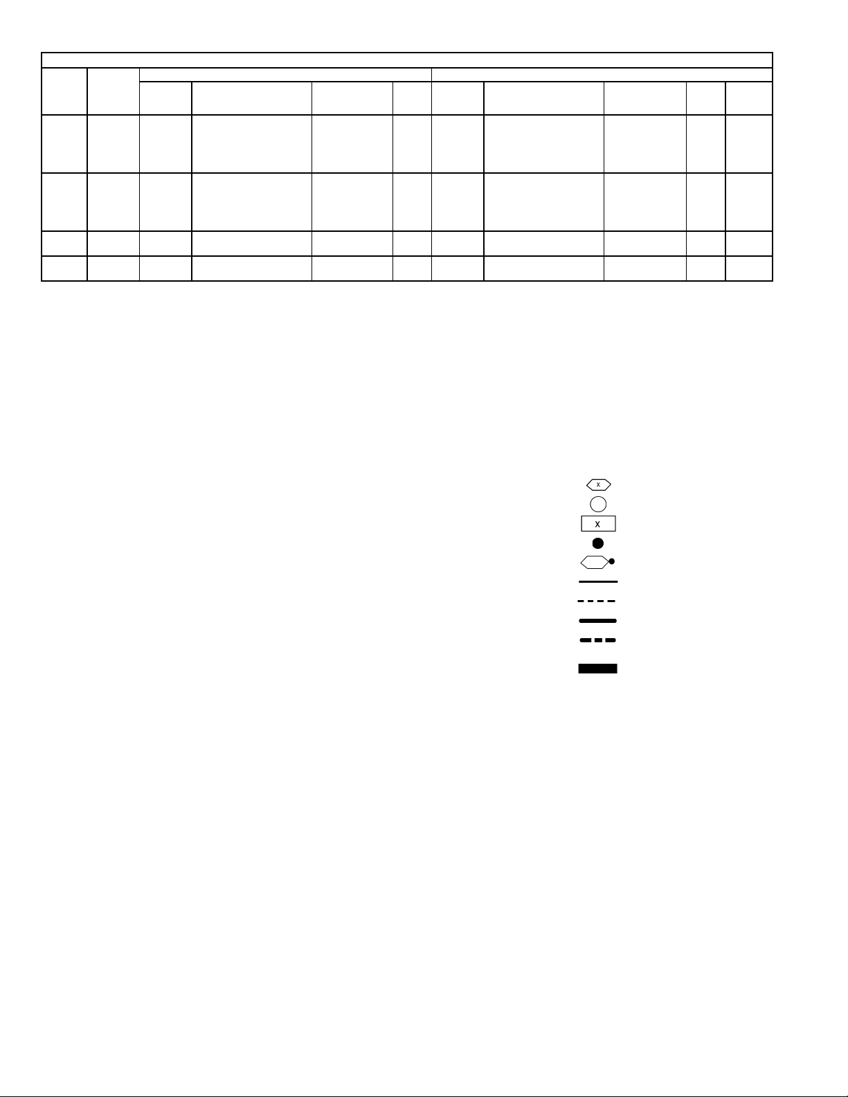
Terminal (Marked)
Terminal (Unmarked)
Terminal Block
Splice
Splice (Marked)
Factory Wiring
Field Control Wiring
Field Power Wiring
Accessory or Optional Wirin
To indicate common poten-
tial only, not to represent
wiring.
—2—
Page 3

OPERATING SEQUENCE
Cooling, Units Without Economizer
When thermos tat calls for cool ing, terminals G and Y1 are
energized. The indoor (evaporator) fan contactor (IFC) and
compressor contactor no. 1 (C1) are energized, and
evaporator-fan motor (IFM), compressor no. 1 and condenser
fan(s) start. The condenser-fan motor(s) runs continuously
while unit is c ooli ng. When t he th e rmo s tat call s fo r a sec on d
stage of cooling by energizi ng Y2, comp ressor con tacto r no. 2
(C2) is energized and compressor no. 2 starts.
Heating, Units Without Economizer (579F180-300)
NOTE: The 579F180-300 units have 2 stages of heat.
When the thermostat calls for heating, power is sent to W on
the IGC (integrated gas unit controller) board. An LED
(light-emitting diode) on the IGC board will be on during
normal operation. A check is ma de to ensure that the rol lout
switch and limit switch are closed. The induced-draft motor
is then energized, and when speed is proven with the hall
effect sensor on the motor, the ignition activation period
begins. The burners will ignite within 5 seconds.
If the burners do not light, there is a 22-second delay before
another 5-second attempt. If the burners still do not light,
this sequence is repeated for 1 5 minutes. After the 15 minutes have elapsed, if the burners still have not lighted, heating is locked out. To reset the control, br eak 24-v power to
the thermostat.
When ignition occ urs the IGC board will continue to mo nitor the condition of the rollout and limit switches, the hall
effect sensor, as well as the flame sensor. If the unit is controlled through a room thermostat set for fan auto., 45 seconds after ignition occurs, the indoor-fan motor will be
energized. If for some reason the overtemperature limit
opens prior to the start of the indoor fan blower, on the next
attempt, the 45-second delay will b e shortened to 5 seconds
less than the time from initiation of heat to when the limit
tripped. Gas will not be interrupted to the burners and heating will continue. Once modified, the fan on delay will
not change back to 45 seconds unless power is reset to the
control.
When additional heat is required, W2 closes and initiates
power to the second stage of the main gas valve. When the
thermostat is satisfied, W1 and W2 open and the gas valve
closes, interrupting the flow of gas to the main burners. If
the call for W1 lasted less than 1 m inute, the heating cycle
will not terminate until 1 minute after W1 became active. If
the unit is controlled through a ro om thermostat set for fan
auto., the indoor-fan motor will continue to operate for an
additional 45 seconds then stop. If the overtemperature limit
opens after the indoor motor is stopped within 10 minutes of
W1 becoming inactive, on the next cycle the time will be
extended by 15 seconds. The maximum delay is 3 minutes.
Once modified, the fan off delay will not change back to
45 seconds unless power is reset to the control.
An LED indicator is provided on the IG C to monitor operation. The IGC is located by removing the side panel and
viewing the IGC through the view port located in the control
box access panel. During normal operation, the LED is continuously on.
Heating, Units Without Economizer (559F180-300, If Accessory or Optional Heater is Installed)
Upon a call for heating through terminal W1, IFC and
heater contactor no. 1 (HC1) are energized. On units
equipped for 2 stages of heat, when additional heat is
needed, HC2 is energized through W2.
Cooling, Units With Economizer
Upon a call for cooling, when outdoor ambient is above the
temperature control setting, the economizer damper moves
to VENT position. The co mpres sors an d evapo rator a nd condenser fans energize.
Upon a first call for cooli ng, when outdoor ambient is be low
the temperature control setting, the evaporator fan starts
and the economizer opens to maintain 53 F leaving-air temperature. The compressors remain off.
Upon a second-stage call for cooling, compressor no. 1 is
energized and mechanical cooling is integrated with economizer cooling. If the outdoor-air temperature drops below
50 F, a cooling lockout switch prevents the compressors from
running.
When supply-air temperature drops below a fixed set point,
the economizer damp er modulate s to maintain the tempera ture at the fixed set point.
Freeze protection thermostats (FPT) are located on the evaporator coil. They detect frost build-up and turn the c ompressors off locking them out an d re qu ir ing a man ual res et. Onc e
frost has melted, the compressors can be reenergized.
Heating, Units With Economizer
Outdoor-air damper stays at VENT position while evaporator fan is operating. Refer to Heating, Units Without
Economizer (579F180-300) and Heating, Units Without
Economizer (559F1 80-300 , If Ac cessor y or O ptio nal He ater i s
Installed) sections on this page for remainder of operating
sequence.
—3—
Page 4

NOTES FOR FIG. 1, 3, 5, 7
1. Compressor and/or fan motors are thermally protected.
Three-phase motors are protected against primary single phasing
conditions.
2. If any of the original wire furnished must be replaced, it must be
replaced with type 90 C or its equivalent.
3. On 208/230-v unit, TRAN1 is factory wired to ORN lead for 230-v
power supply. If unit is to be run on 208-v power supply, TRAN1 must
be rewired. Disconnect the BLK wire on TRAN1 and connect wire to
208-v RED wire. Insulate 230-v ORN wire.
5. Indoor fan circuit breaker must trip amps value is equal to or less
than 140% FLA.
NOTES FOR FIG. 2, 4, 6, 8
1. Compressor and/or fan motors are thermally protected.
Three-phase motors are protected against primary single phasing
conditions.
2. If any of the original wire furnished must be replaced, it must be
replaced with type 90 C or its equivalent.
3. Jumpers are omitted when unit is equipped with an economizer.
5. Indoor fan circuit breaker must trip amps value is equal to or less
than 140% FLA.
NOTES FOR FIG. 9, 11, 13, 15
1. Compressor and/or fan motors are thermally protected.
Three-phase motors are protected against primary single phasing
conditions.
2. If any of the original wire furnished must be replaced, it must be
replaced with type 90 C or its equivalent.
3. Jumpers are omitted when unit is equipped with an economizer.
4. Indoor fan circuit breaker must trip amps value is equal to or less
than 140% FLA.
5. On 208/230-v unit, TRAN1 is factory wired to ORN lead for 230-v
power supply. If unit is to be run on 208-v power supply, TRAN1 must
6. The CLO locks out the compressor to prevent short cycling on compressor overload and safety devices. Before replacing CLO, check
these devices.
7. Jumpers are omitted when unit is equipped with an economizer.
8. Number(s) indicate the line location of used contacts. A bracket over
2 numbers signifies a single-pole, double-throw contact. An underlined number signifies a normally closed contact. A plain (no line)
number signifies a normally open contact.
6. The CLO locks out the compressor to prevent short cycling on compressor overload and safety devices. Before replacing CLO, check
these devices.
7. Number(s) indicate the line location of used contacts. A bracket over
2 numbers signifies a single-pole, double-throw contact. An underlined number signifies a normally closed contact. A plain (no line)
number signifies a normally open contact.
be rewired. Disconnect the BLK wire on TRAN1 and connect wire to
208-v RED wire. Insulate 230-v ORN wire.
6. The CLO locks out the compressor to prevent short cycling on compressor overload and safety devices. Before replacing CLO, check
these devices.
7. Number(s) indicate the line location of used contacts. A bracket over
2 numbers signifies a single-pole, double-throw contact. An underlined number signifies a normally closed contact. A plain (no line)
number signifies a normally open contact.
NOTES FOR FIG. 10, 12, 14, 16
1. Compressor and/or fan motors are thermally protected.
Three-phase motors are protected against primary single phasing
conditions.
2. If any of the original wire furnished must be replaced, it must be
replaced with type 90 C or its equivalent.
3. Jumpers are omitted when unit is equipped with an economizer.
4. Indoor fan circuit breaker must trip amps value is equal to or less
than 140% FLA.
5. If unit is to be run on 460-v power supply, TRAN1 must be wired to
BLK wire.
6. The CLO locks out the compressor to prevent short cycling on compressor overload and safety devices. Before replacing CLO, check
these devices.
7. Number(s) indicate the line location of used contacts. A bracket over
2 numbers signifies a single-pole, double-throw contact. An underlined number signifies a normally closed contact. A plain (no line)
number signifies a normally open contact.
—4—
Page 5
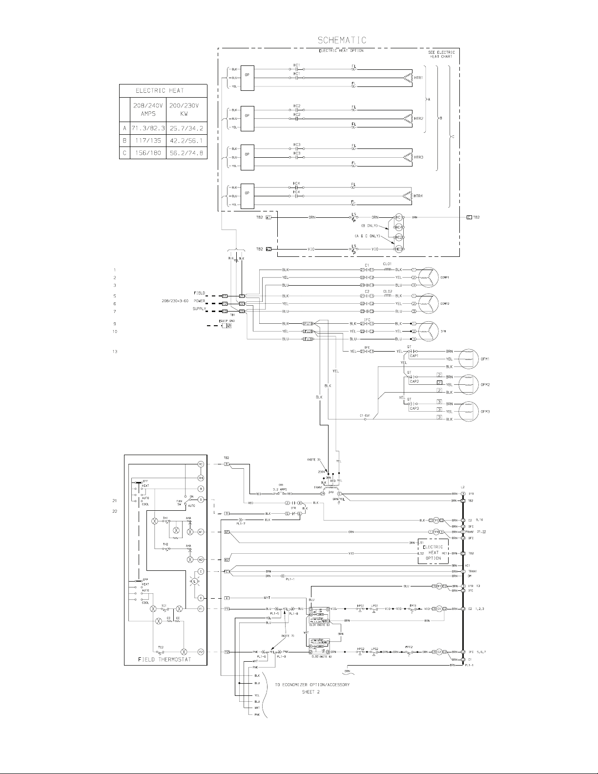
Fig. 1 — Label Diagram — 559F180, 208/230-3-60 Units
—5—
Page 6
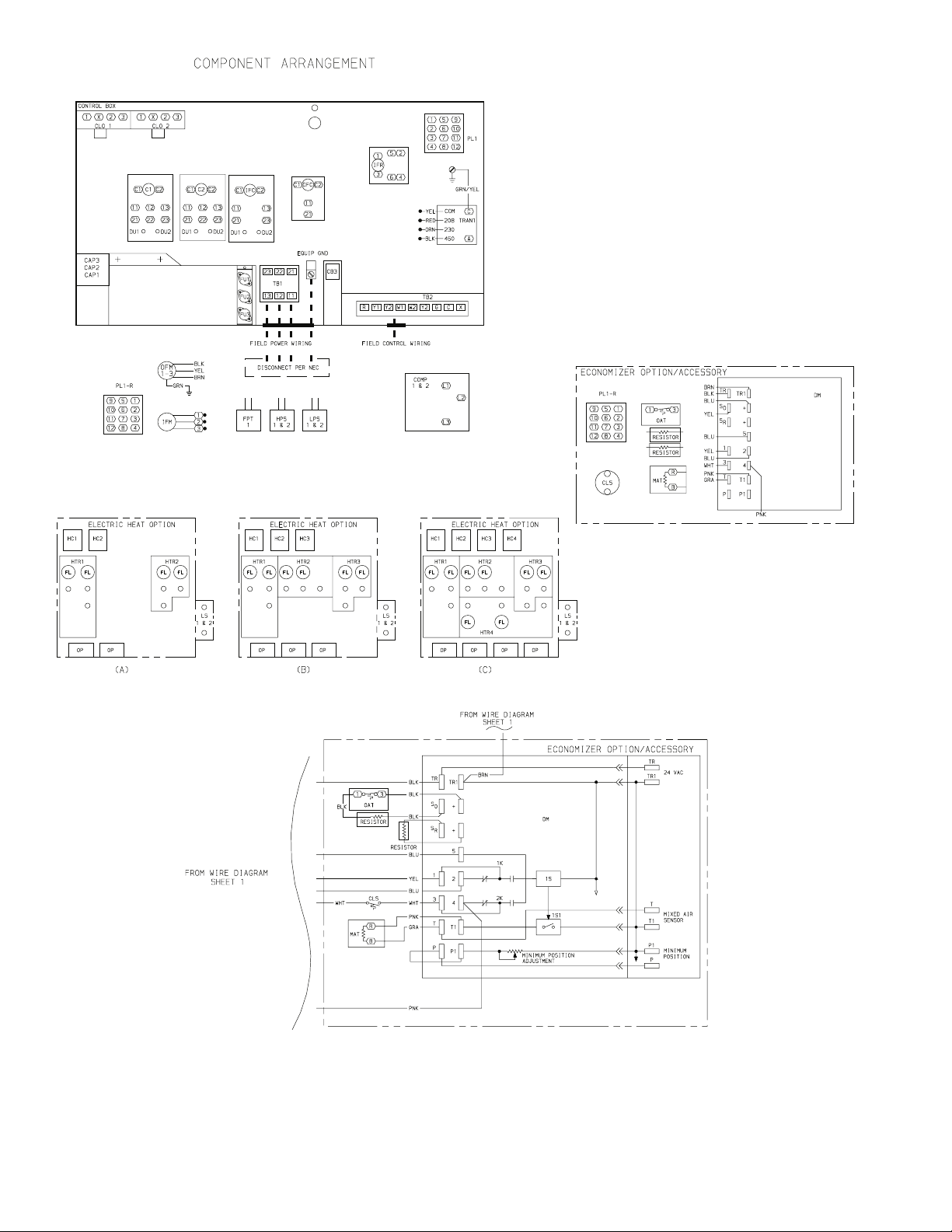
Fig. 1 — Label Diagram — 559F180, 208/230-3-60 Units (cont)
—6—
Page 7
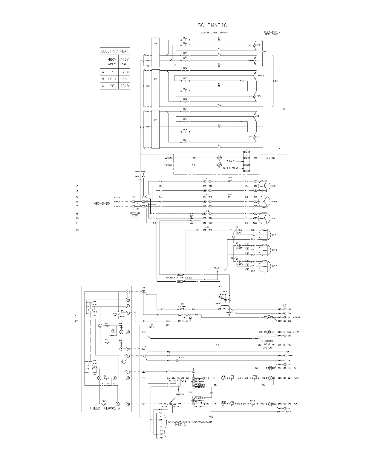
Fig. 2 — Label Diagram — 559F180, 460-3-60 Units
—7—
Page 8
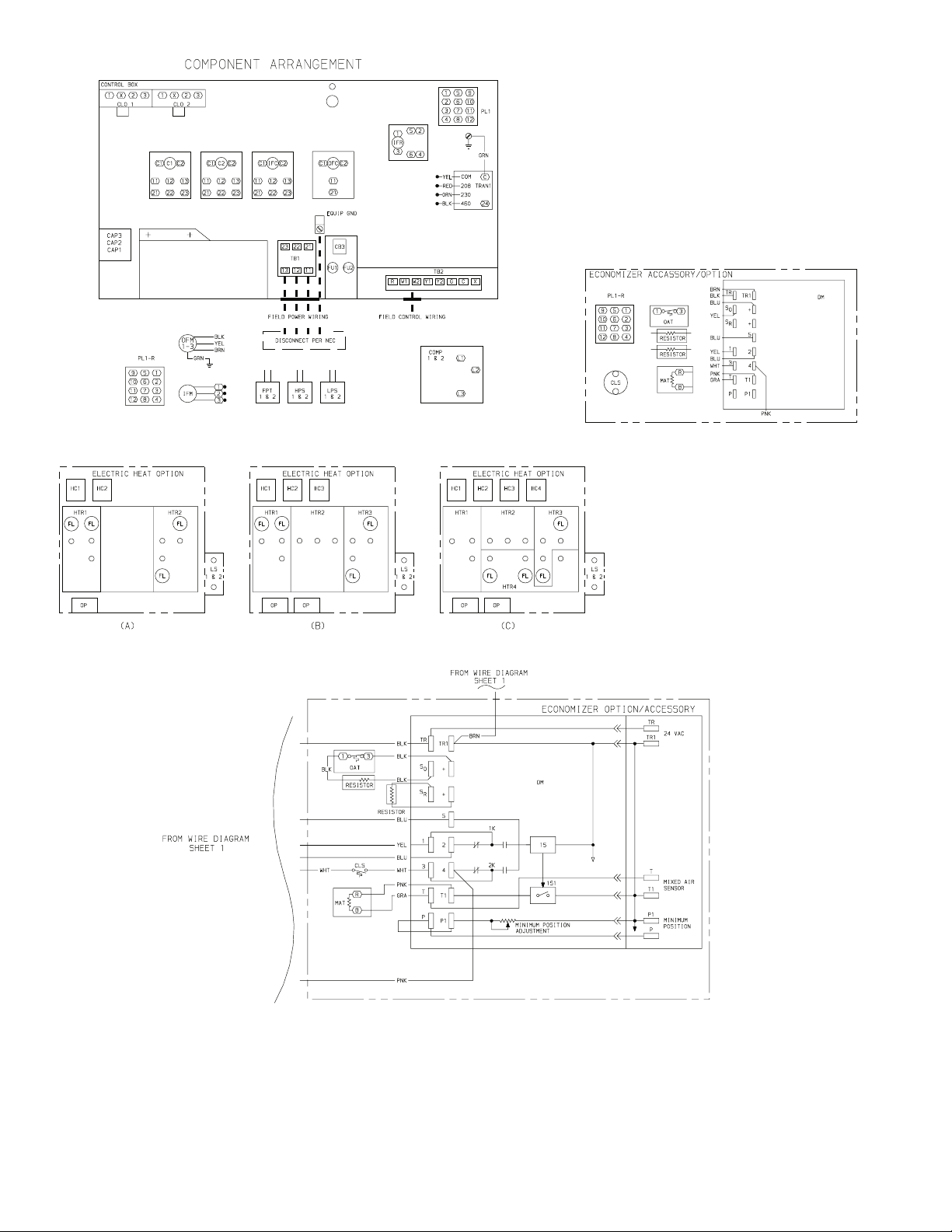
Fig. 2 — Label Diagram — 559F180, 460-3-60 Units (cont)
—8—
Page 9
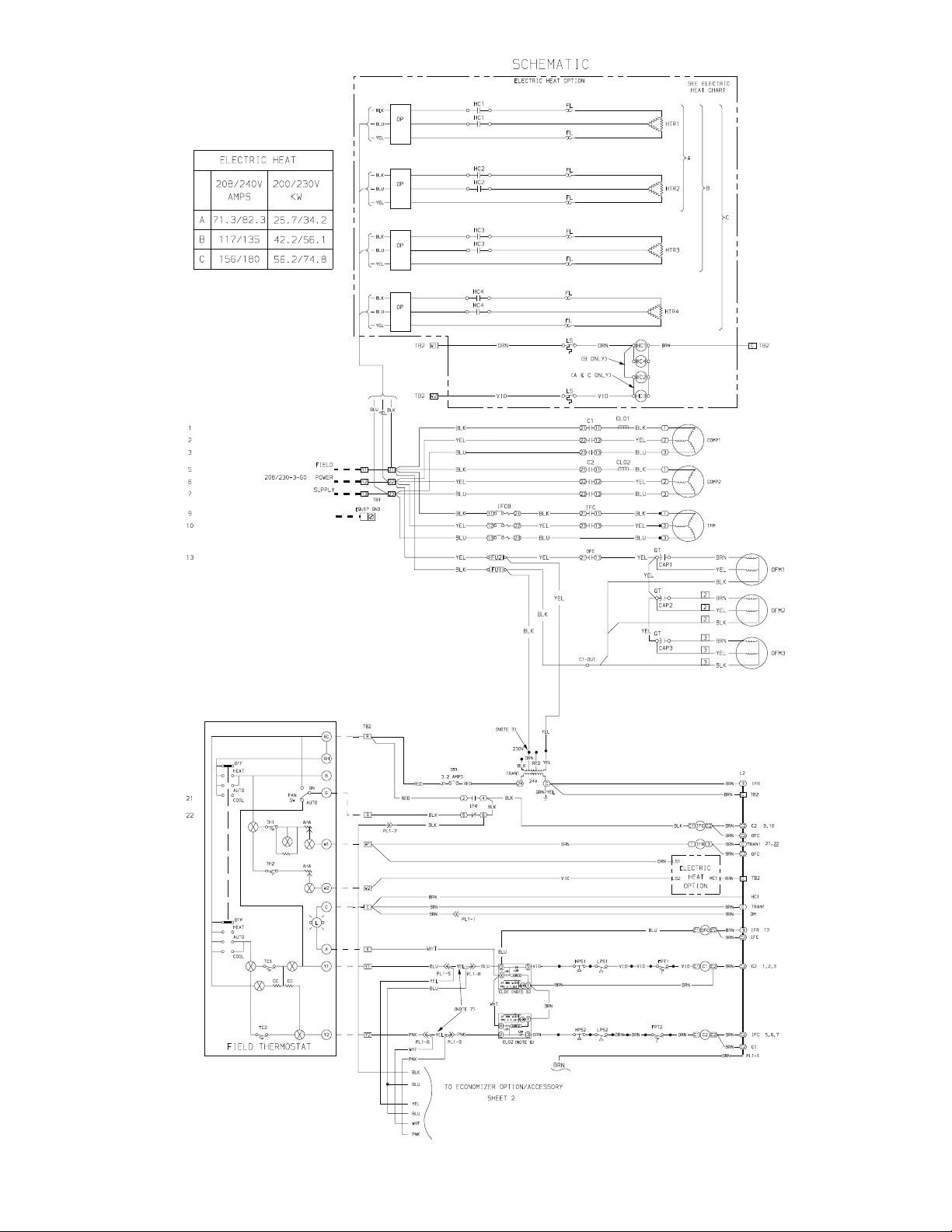
Fig. 3 — Label Diagram — 559F216, 208/230-3-60 Units
—9—
Page 10
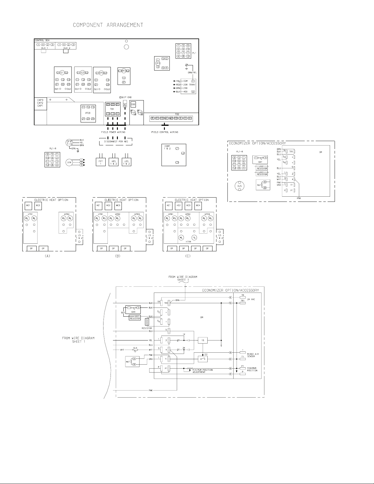
Fig. 3 — Label Diagram — 559F216, 208/230-3-60 Units (cont)
—10—
Page 11
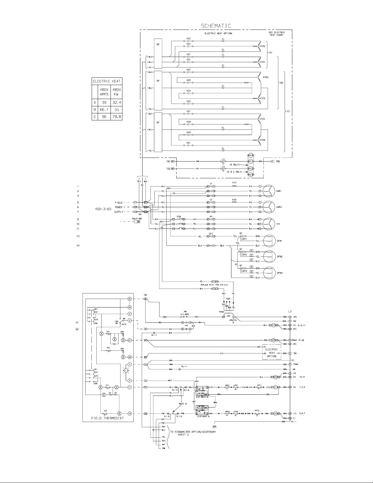
Fig. 4 — Label Diagram — 559F216, 460-3-60 Units
—11—
Page 12
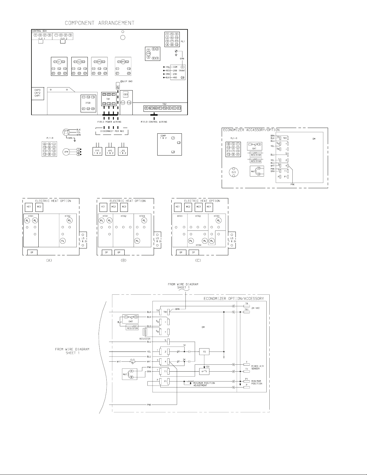
Fig. 4 — Label Diagram — 559F216, 460-3-60 Units (cont)
—12—
Page 13
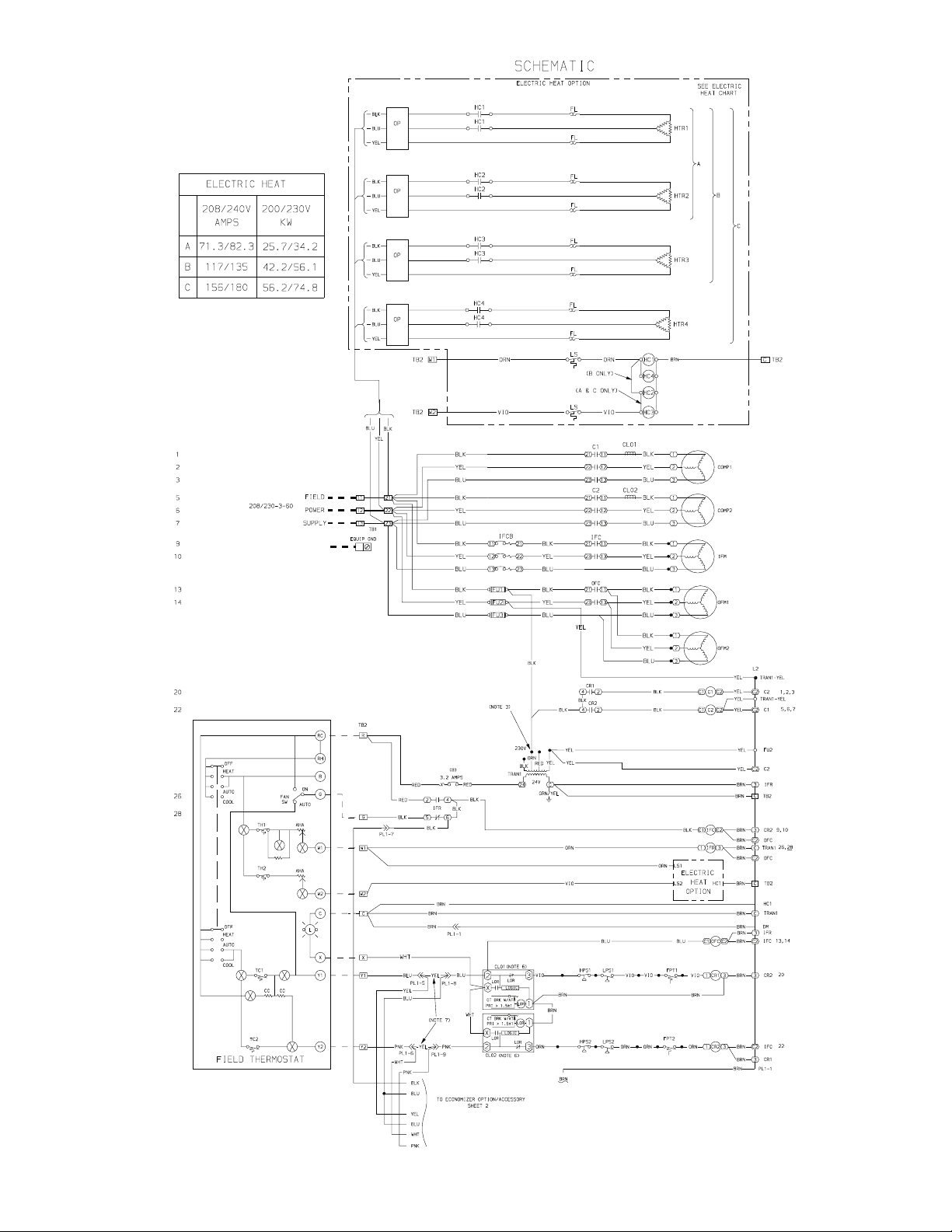
Fig. 5 — Label Diagram — 559F240, 208/230-3-60 Units
—13—
Page 14

Fig. 5 — Label Diagram — 559F240, 208/230-3-60 Units (cont)
—14—
Page 15
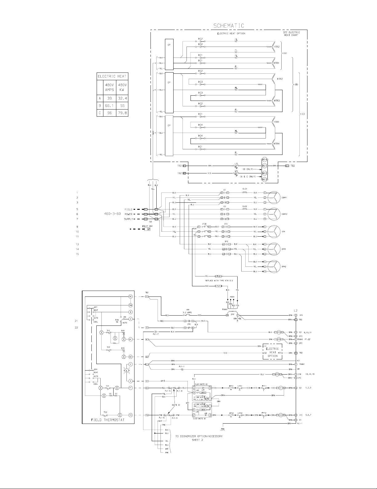
Fig. 6 — Label Diagram — 559F240, 460-3-60 Units
—15—
Page 16

Fig. 6 — Label Diagram — 559F240, 460-3-60 Units (cont)
—16—
Page 17

Fig. 7 — Label Diagram — 559F300, 208/230-3-60 Units
—17—
Page 18

Fig. 7 — Label Diagram — 559F300, 208/230-3-60 Units (cont)
—18—
Page 19

Fig. 8 — Label Diagram — 559F300, 460-3-60 Units
—19—
Page 20

Fig. 8 — Label Diagram — 559F300, 460-3-60 Units (cont)
—20—
Page 21

Fig. 9 — Label Diagram — 579F180, 208/230-3-60 Units
—21—
Page 22

Fig. 9 — Label Diagram — 579F180, 208/230-3-60 Units (cont)
—22—
Page 23

Fig. 10 — Label Diagram — 579F180, 460-3-60 Units
—23—
Page 24

Fig. 10 — Label Diagram — 579F180, 460-3-60 Units (cont)
—24—
Page 25

Fig. 11 — Label Diagram — 579F216, 208/230-3-60 Units
—25—
Page 26

Fig. 11 — Label Diagram — 579F216, 208/230-3-60 Units (cont)
—26—
Page 27

Fig. 12 — Label Diagram — 579F216, 460-3-60 Units
—27—
Page 28

Fig. 12 — Label Diagram — 579F216, 460-3-60 Units (cont)
—28—
Page 29

Fig. 13 — Label Diagram — 579F240, 208/230-3-60 Units
—29—
Page 30

Fig. 13 — Label Diagram — 579F240, 208/230-3-60 Units (cont)
—30—
Page 31

Fig. 14 — Label Diagram — 579F240, 460-3-60 Units
—31—
Page 32

Fig. 14 — Label Diagram — 579F240, 460-3-60 Units (cont)
—32—
Page 33

Fig. 15 — Label Diagram — 579F300, 208/230-3-60 Units
—33—
Page 34

Fig. 15 — Label Diagram — 579F300, 208/230-3-60 Units (cont)
—34—
Page 35

Fig. 16 — Label Diagram — 579F300, 460-3-60 Units
—35—
Page 36

Fig. 16 — Label Diagram — 579F300, 460-3-60 Units (cont)
—36—
Page 37

CAP —
EFM —
EMC —
FU —
A. 460 V (PART NO. CRPWREXH008A00)
B. 208/230 V (PART NO. CRPWREXH009A00 OR CRPWREXH008A00 WITH FIELD REWIRING)
LEGEND
Capacitor
Exhaust Motor Contactor
Exhaust Fan Motor
Fuse
Fig. 17 — Power Exhaust Power Wiring
LEGEND
EMC —
IFC —
Exhaust Motor Contactor
Indoor (Evaporator) Fan Contactor
Fig. 18 — Accessory Power Exhaust Control Wiring
—37—
Page 38

C—
CLO —
CPM —
CR —
FPT —
*Time Guard II device connections.
Contactor
Cooling Lockout
Compressor Protection Module
Control Relay
Freeze Protection Thermostat
Fig. 19 — Time Guard® II Device Wiring
LEGEND
HPS —
LPS —
PL —
TB —
TG II —
High-Pressure Switch
Low-Pressure Switch
Plug
Terminal Block
Time Guard II Device
—38—
Page 39

LEGEND
Field Wiring
Field-Supplied Switch
See Legend on page 2.
*Included in power exhaust accessory.
OPERATING MODES
Building Pressurization: Evaporator fan on, economizer energized to fully open position,
BP —
Evacuation: Evaporator fan off, economizer energized to fully closed position,
E—
Complete Unit Shutdown: Breaks 24-v power to the thermostat.
SD —
Smoke Purge: Evaporator fan on, economizer energized to fully open position,
SP —
power exhaust disabled.
power exhaust on (open).
power exhaust on.
Fig. 20 — Smoke Control/Fire Shutdown Wiring; 559F180-300
—39—
Page 40

CLOSED ON
BP,SP,E
OPEN
ON SD
OPEN ON E
CLOSED ON BP
OPEN
ON BP
*
EMC
EAS
See Legend on page 2.
*Included in power exhaust accessory.
All switches are field supplied.
NOTE:
OPERATING MODES
Building Pressurization: Evaporator fan on, economizer energized to fully open position,
BP —
Evacuation: Evaporator fan off, economizer energized to fully open position,
E—
Complete Unit Shutdown: Breaks 24-v power to the thermostat.
SD —
Smoke Purge: Evaporator fan on, economizer energized to fully open position,
SP —
power exhaust disabled.
power exhaust on (open).
power exhaust on.
COMPRESSOR WIRING
SWITCH CLOSES
ON BP,SP,E
Fig. 21 — Smoke Control/Fire Shutdown Wiring; 579F180-300
—40—
Page 41

C—
CLO —
CPM —
CR —
FPT —
NOTE:
correct application.
Contactor
Compressor Lockout
Compressor Protection Module
Control Relay Factory-Supplied Wiring
Freeze Protection Thermostat Field-Supplied Wiring
See Lower Outdoor Ambient Operation Accessories table on page 2 for
LEGEND
HPS —
LPS —
TDR —
High-Pressure Switch
Low-Pressure Switch
Time-Delay Relay
Fig. 22 — Winter Start Kit Wiring
LEGEND
SW —
NOTE:
Switch
Field Wiring
Factory Wiring
See Lower Outdoor Ambient Operation Accessories table on page 2 for correct application.
Fig. 23 — Mild/Low Ambient Control — 559/579F180 and 216 Units (10 F Ambient Control)
—41—
Page 42

LEGEND
OFM —
NOTE:
Outdoor (Condenser) Fan Motor
Field Wiring
Factory Wiring
See Lower Outdoor Ambient Operation Accessories table on page 2 for correct application.
Fig. 24 — Motormaster® I Head Pressure Control Wiring; 559/579F180 and 216 Units
(–20 F Ambient Control)
SENSOR
LOCATION
HAIRPIN END
559/579F180 559/579F216
NOTES:
1. All sensors are located on the eighth hairpin up from the bottom.
2. See Lower Outdoor Ambient Operation Accessories table on page 2 for correct application.
SENSOR
LOCATION
Fig. 25 — Motormaster I Control Sensor Locations;
559/579F180 and 216 Units
—42—
HAIRPIN END
Page 43

NOTES:
Accessories table on page 2 for correct
application.
1. CR1 is replaced by C1 in 460-v units.
2. See Lower Outdoor Ambient Operation
Plug
Primary
Time-Delay Relay
PL —
PRI —
TDR —
—43—
LEGEND
High-Pressure Switch
Indoor (Evaporator) Fan Contactor
Indoor (Evaporator) Fan Relay
Lockout Relay Factory-Supplied Wiring
Low-Pressure Switch Field-Supplied Wiring
Outdoor (Condenser) Fan Contactor
Outdoor (Condenser) Fan Motor
HPS —
IFC —
IFR —
LOR —
LPS —
OFC —
OFM —
Breaks with Amps
Contactor
Compressor Lockout
Control Relay
Circuit
Freeze Protection Thermostat
Head Pressure Control Thermostat
BRK W/AT —
C—
CLO —
CR —
CT —
FTP —
HPCT —
Fig. 26 — HPCT, OFC2, and TDR Wiring — 25 F Ambient Kit; 559/579F240 and 300 Units
Page 44

559/579F240 AND 300, 208/230-3-60 UNITS
559/579F240 AND 300, 460-3-60 UNITS
C—
FU —
IFCB —
MMSN —
Contactor
Fuse
Indoor Fan Circuit Breaker
Motormaster Sensor
LEGEND
OFC —
OFM —
TB —
Outdoor (Condenser) Fan Contactor
Outdoor (Condenser) Fan Motor
Terminal Block
NOTE:
Operation Accessories table on page 2
for correct application.
Fig. 27 — Motormaster® III Control Wiring; 559/579F240 and 300 Units
—44—
See Lower Outdoor Ambient
Page 45

SENSOR
LOCATION
SENSOR
LOCATION
HAIRPIN END
559/579F240 559/579F300
NOTES:
1. All sensors are located on the eighth hairpin up from the bottom.
2. See Lower Outdoor Ambient Operation Accessories table on page 2 for correct application.
Fig. 28 — Motormaster® III Control Sensor Locations;
559/579F240 and 300 Units
HAIRPIN END
—45—
Page 46

Page 47

Page 48

Copyright 2000 Bryant Heating & Cooling Systems CATALOG NO. 5355-901
 Loading...