

Page 1
Bryant
Airconditioning
Company
installation instructions
SELF-CONTAINED
ELECTRIC COOLING UNITS
559B
Sizes 024, 030,
036, 042, & 048
Series E
The Model 559B unit is a complete cooling system, with
provisions for addition of accessory electric heaters. Units
are air cooled, designed for outdoor installation, and may
be connected into existing duct system. Required con
nections include air ducts, condensate drain, and high- and
low-voltage wiring. A field-supplied filter box must be in
stalled in return air duct.
When optional electric heaters are being installed, see
instructions beginning on page 8 of this publication
for procedures.
TRANSPORTATION DAMAGE
File claim with shipping company if shipment is damaged
or incomplete. Move unit to installation site in upright
position.
Important—Read Before Installing
1. Check all local codes and ordinances that could affect
installation of equipment.
2. Be sure power supply available (voltage, hertz, and
phase) corresponds to that specified on unit rating
plate.
3. Check electrical service provided by utility for building
to be sure service capacity is sufficient to handle load
imposed by unit.
4. Refer to dimensional drawing for locations of elec
trical, condensate drain, and duct connections before
setting unit in place.
Installation consists of the following steps;
I. Locating and Mounting Unit
II. Connecting Ductwork
III. Connecting Condensate Drain
IV. Electrical Connections
V. Startup and Adjustment
VI. Maintenance
VII. Instructions to Owner
I. LOCATING AND MOUNTING UNIT
Place unit on a solid, level, concrete pad. Pad should be
minimum of 3 inches high, extend about 6 inches from both
sides and front of unit, and must not extend more than 1
inch from back (duct side) of unit. Insert sheet of tar-base
construction felt paper between unit and pad.
Unit does not need to be secured to pad because there are
no refrigerant lines extending outside of unit that could be
damaged.
Be sure grass and shrubs do not interfere with condenser
airstream. If necessary, extend gravel apron around pad.
Place duct side against building structure so ductwork can
not be seen from outside.
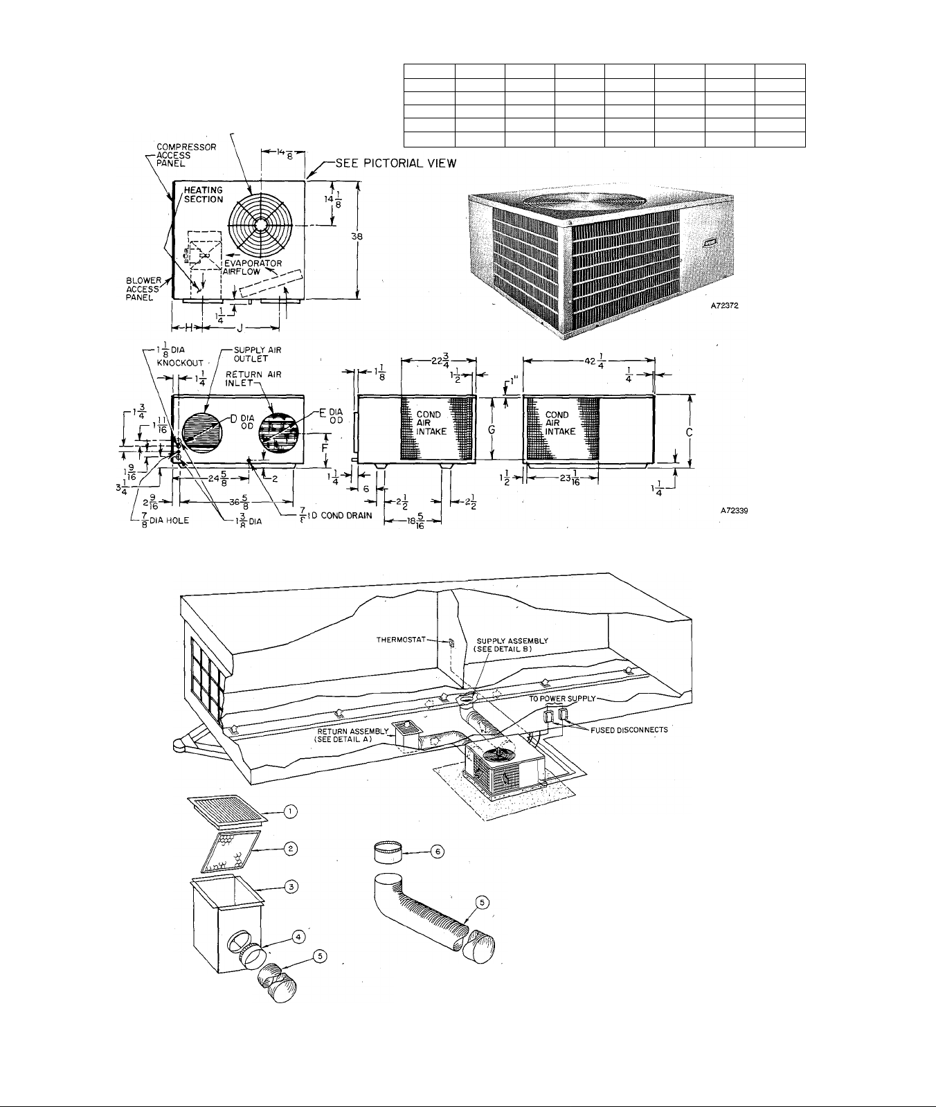
When installing unit, allow sufficient space for condenser
airflow clearance, wiring, and servicing unit. See Figure 2.
Position unit so water from roof will not pour directly on
top of unit. Do not locate unit under eaves.
Recornmended minimum service clearance;
18 inches all sides except duct side
0 inches bottom
36 inches top
Cancels: 39559D47
Figure 1—Model 559B
II. CONNECTING DUCTWORK
39559DP61
6/1/74
Flanges are provided on unit for duct connections. See
Figure 2 for unit connection sizes and locations. Use
weathertight connectors between ductwork and unit to
prevent transmission of vibration.
Ductwork should be selected and sized according to Part 2
of Bryant Air Distribution Manual. All ductwork in un
conditioned space should be insulated and weatherproof if
used outdoors.
t'.\l”JT()\; D'l nol opi-rau* unit longer than .“) minutes
Filters must be located in return airstream. Recommended
sizes are shown in Table II. When electric heaters are
installed, use an asbestos (or similar heat-resistant ma
terial) connector between ductwork and unit supply duct
connection.
When flexible duct is used, friction loss in straight runs is
approximately double amount found in Bryant Air
Distribution Manual, Part 2, for air duct design.
It is recommended that rigid elbows should be used for
bends. If rigid elbows are not used, ratio of centerline bend,
radius to duct diameter (R/D) should be at least 1.5 for
minimum friction loss. If rectangular ducts are used over
unit round connections, unit entering pressure loss must be
considered when designing system.
\\ \KMN(i l><> iiol •lull hull-- III ,11-1.1 sliiiMM in
It is also recommended that abrupt duct expansions and
contractions be avoided.
NOTE: Mobile home duct kits (which include a return air
filter box, filter, floor grille, flexible duct sections, and in
stallation hardware) are available for mobile home in
stallation. See your Bryant Distributor.
Mobile Home Duct Design
Design duct system to have friction loss of between 0.25 in.
wc and 0.70 in. wc for proper unit operation. Insulated
flexible ductwork (1-ft inside diameter) of weatherproof
type is recommended. Do not reduce duct inside diameter
below 1 ft. Combined length of supply and return ducts
should not exceed 20 ft, with minimum supply duct length
Page 2
^CONDENSER AIR DISCHARGE
20" DIAMETER
, 1
DIMENSIONS IN INCHES
SIZE
024
C
17-5/8
030 17-5/8 12
036 19-5/8 14 14
042 27-5/8 14
048 27-5/8
D
12
14
E F G H
12 10-1/4 14-1/2
12 10-1/4 14-1/2
11-1/4 16-1/2
14 12-1/4
14
12-1/4 24-1/2
24-1/2 9-5/8
8-5/8 25-5/16
8-5/8
8-5/8 25-5/16
9-5/8
J
25-5/16
24-5/16
24-5/16
LOW-VOLT CONN (2) )î:NOCKOUTS
’(RUBBER TUBE)
Figure 2 — Dimensional Drawing
Q RETURN AIR FLOOR GRILLE
(T) 20x25 xl DISPOSABLE FILTER
Q) RETURN AIR FILTER BOX
(4) QUICK-CONNECT COLLAR
(5) flexible DUCT
(i) TAP-IN COLLAR
DETAIL A
(RETURN ASSEMBLY)
DETAIL B
(SUPPLY ASSEMBLY)
Figure 3 — Typical Installation
-2-
--------
CONTROL WIRING
--------
POWER WIRING
CONDENSER AIRFLOW
EVAPORATOR AIRFLOW
Page 3
MODEL
Rated Cooling Capacity* Btuh
Nameplate Voltage-Freq-Phase
Operating Voltage Range
Compressor Motor FLA
Locked Rotor Amps
Condenser Fan Motor** HP
Full Load Amps
Evaporator Blower Motor** HP
Full Load Amps
Rated Total Power Consumption KWH
Electrical Connections
Unit Full Load Amps
Unit Ampacity for Electrical
Conductor Sizing
Min Branch Circuit Wire
Size 60°C Temp Rating Copper
Conductor*** AWG No.
Max Line Length**** Ft
Largest Wire Size Line-Voltage Con
nections Will Accommodate AWG No.
Max Branch Circuit Fuse Size Amps
Refrigerant type/lbs-ozs
Evaporator Airflow CFM
Approximate Shipping Weight lbs
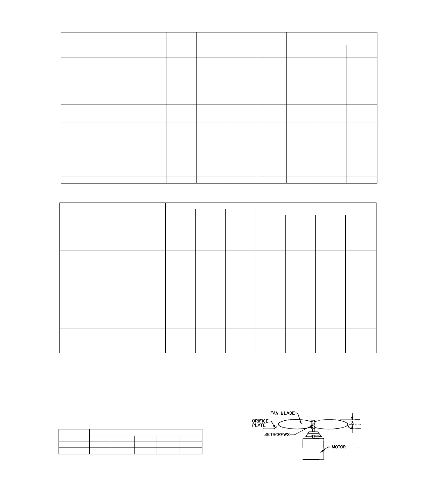
TABLE I—RATINGS AND PERFORMANCE
559B-024-E
24,000
230-60-1
207-254 207-254
15.7 19.5
72 88
1/5 1/5
1.3
1/4 1/3
2.0
3.5
19.0 23.9
22.9 28.8
10 10
119 95
4 4
25
R-22/2-6
900 1125
265
230-60-1 208-60-3
R-22/3-0
285
1.3 1.4
3.1
4.6
30
559B-030-E
30,000
187-229
12.3 11.1
70
1/5
1/3
2.9
4.6
16.6
19.7
12 12 8 10
92 110
4
25 20 40 30 25
R-22/3-0
1125 1125 1350
285 285 305 305
230-60-3 230-60-1
207-254 207-254
60 100 80
1/5
1.3 1.8 2.1
1/3 1/3 1/3
3.1 3.6 3.8
4.6
15.5
18.3 35.4 24.9
4
R-22/3-0
24.0
1/4
5.7
29.4
122 115
4 4
R-22/3-10
5S9B-036-E
35,000
208-60-3
187-229
15.2
1/4
5.7
21.1
R-22/3-10
1350 1350
R-22/3-10
230-60-3
207-254
14.0
70
1/4
1.8
1/3
3.6
5.7
19.4
22.9
10
142
4
305
MODEL
Nameplate Voltage-Freq-Phase
Operating Voltage Range
Locked Rotor Amps
Full Load Amps
Full Load Amps
Electrical Connections
Unit Full Load Amps
Unit Ampacity for Electrical
Conductor Sizing 37.4
Min Branch Circuit Wire
Size 60°C Temp Rating Copper
Max Line Length**** Ft
Largest Wire Size Line-Voltage Con
nections Will Accommodate AWG No.
Max Branch Circuit Fuse Size Amps
Rated Cooling Capacity* Bfuh
Compressor Motor FLA
Condenser Fan Motor** HP
Evaporator Blower Motor** HP
Rated Total Power Consumption KWH
Conductor*** AWG No.
Refrigerant type/lbs-ozs
Evaporator Airflow CFM
Approximate Shipping Weight lbs 345
230-60-1
R-22/4-13 R-22/4-13
42,000 . 41,000 42,000 48,000
207-254
25.0
111
1/4 1/4 1/4
1.8
1/2
4.2
6.3 6.3
31.0
8 10
116
4
40 30
1570 1570 1570 1800
559B-042-E
208-60-3 230-60-3
187-229
16.9 15.3
92
2.1
1/2 1/2 1/2 1/2 1/2 1/2
4.4
23.4
27.6
103
4 4 4
345 345
207-254
92 118 90 78.5 39.3
1.8
4.2 4.9 5.1 4.9 4.9
6.3 7.2 7.2 7.2
21.3
25.1 40.0 33.3
10 8
130
30
R-22/4-13
230-60-1 208-60-3
207-254 187-229
26.5
1/4
1.9
33.3
108
45
R-22/4-11
367
559B-048-E
20.9 18.0 9.1
1/4 1/4
2.1 1.8 1.8
28.1 24.7
8 10 12
137
4
35 30 20
R-22/4-11 R-22/4-11 R-22/4-11
1800 1800 1800
367 367 367
*Rated in Accordance with ARI Standard 210-66.
**Condenser fan and evaporator motors are single phase.
***If other than 60 °C copper conductor is used, determine size from unit ampacity and the National Electrical Code. Voltage drop of
wire must be less than 2% of unit rated voltage.
****Wire length shown is measured one way along the wire path between unit and service panel for minimum voltage drop.
230-60-3
207-254 414-508
29.2 18.1
112 225
4
460-60-3
1/4
7.2
15.8
4
Unit Size
Disposable
Permanent
TABLE II—FILTER DIMENSIONS
Minimum Filter Size or Equivalent, Inches
024 030
16x20x1 20x20x1
12x20x1 16x20x1 20x20x1 20x20x1 20x25x1
036
20x25x1
042
25x25x1
048
25x25x1
X = Size 024, 030, & 036................................................................................1-3/4 in.
Size 042 & 048 ............................................................................................2 in.
Figure 4—Required Condenser
Fan Position
-3-
Page 4
DO NOT DRILL HOLES IN SHADED
AREA WHEN INSTALUNG
RECTANGULAR DUCTS
Figure 5
of 6 ft and minimum return duct length of 3 ft. Do not
operate unit longer than 5 minutes without ductwork.
Refer to Bryant Air Distribution Manual, Part 2, for air
duct design.
Flanges are provided on unit for duct connections. See
Figure 2 for connection sizes and Figure 3 for typical duct
installation.
Supply Air Connection in Mobile Home
Connect flexible duct to unit supply air connection at ap
proximate center of trailer. Install turning vanes in main
supply duct directly above elbow connection, using stan
dard sheet metal practices.
Return Air Connection in Mobile Home
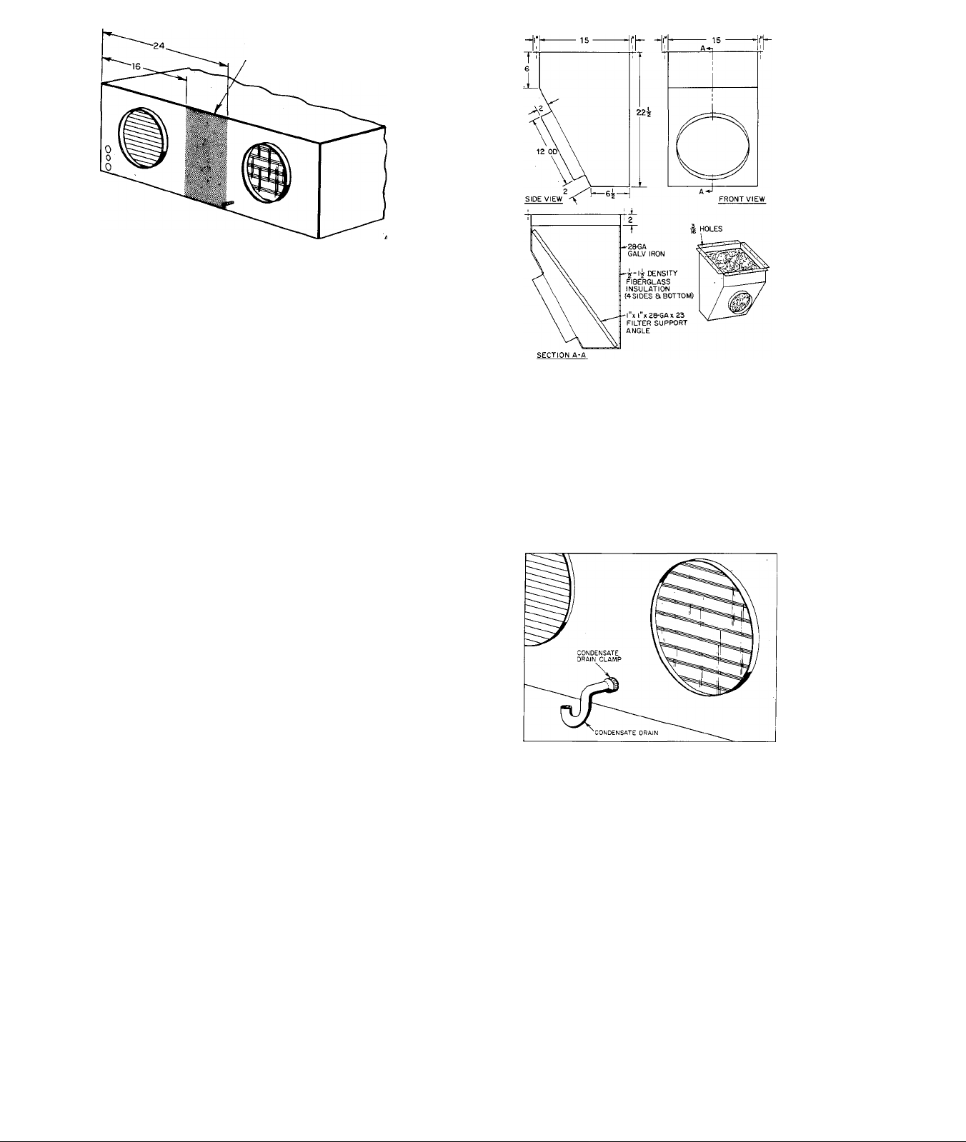
Purchase or field-fabricate a filter box. Suggested minimum
filter box dimensions are shown in Figure 6. At ap
proximate center of trailer, cut a return air opening in floor.
Locate opening where it will not be obstructed by furniture.
Size opening to accept filter box. Cut a hole in carpet or
floor covering to sarne size as filter box floor opening. En
sure electrical wiring or main structural supports are not
accidentally cut. Insert filter box thru floor opening.
Weather-seal floor connection in accordance with good con
struction practice. Insert filter in filter box, and cover with
return air grille.
Connect flexible duct to filter box. Extend duct from filter
box to unit return air connection. When existing furnace is
kept in system: During heating season, insert sheet metal
panel beneath return air grille and over filter to prevent air
movement thru cooling unit.
When furnace is removed from system, blank-off original
furnace floor connection.
III. CONNECTING CONDENSATE DRAIN
The unit is designed to dispose of accumulated water
through condensate drain hose on unit. It is recommended
that a drain line that includes a trap should be installed to
avoid possibility of abnormal negative fan pressure preven
ting complete drainage of condensate. If drain connection is
not practical or feasible, a factory-supplied condensate trap
(taped at supply duct connection) must be installed for
proper drainage. See Figure 7.
IV. ELECTRICAL CONNECTIONS
Field wiring must comply with National Electrical Code
and local codes. Install a branch circuit fused disconnect of
adequate size to handle unit current load. Provide separate
fused disconnect for electric heaters.
Voltage to unit during operation must be within ±10% of
voltage indicated on rating plate.
W.-VRNI.N'Ci: Failure berause of operation of unit on im
proper line voltage constitutes abuse and is not coveretl by
Brvant warr.mtv.
Figure 6 — Minimum Dimensions-Return
Air Filter Box
Connect line-power leads from fused disconnect(s) to line
power leads located in junction box. Screw connectors,
which are suitable for aluminum or copper wires, are
provided. See Figures 8 and 9. Tape screw connectors after
connections are completed. Table I is provided to assist in
staller in selecting proper wire and fuse sizes.
Thermostat connections are made to color-coded wires
located in junction box. See Figures 8 and 9. Be sure colorcoded wires not used are adequately and individually taped
at end.
Rgure 7 —Condensate Drain Connection
NOTE: When using Model 883 (P/N 34427D03O) ther
mostat with optional electric heat package, W and J ter
minals on thermostat must be jumpered to ensure fan
operation when thermostat is in HEAT position.
V. STARTUP AND ADJUSTMENT
Before starting system, make an initial overall inspection.
1. Check to be sure all wiring connections, including fac
tory connections, have been completed and are tight.
2. Inspect all supply ducts and grilles to ensure proper
adjustment.
3. Check to ensure air filters are in place.
4. Inspect refrigerant piping for damage or leaks that
might have occurred during shipment.
5. Check for correct position of condenser fan blade in fan
orifice plate. See Figure 4 for setting.
6. Check to ensure all tools and loose parts have been
removed.
7. Check to ensure all panels and covers are in place.
Following initial inspection, unit may be started and ad-
-4-
Page 5

justed for proper airflow.
Recommended evaporator airflow is 350 to 450 CFM per
12,000 Btuh.
1. Set thermostat to call for cooling, thus energizing unit.
2. Measure static pressure in duct system at unit.
3. To determine airflow across evaporator coil, see Tables
III through VII.
Model 559B utilizes a direct-drive blower, factory-wired on
high-speed tap. If airflow is incorrect, blower speed can be
adjusted as follows:
1. Disconnect electric power to unit.
2. Disconnect cooling relay lead from high-speed tap
(black wire). Tape end of wire removed.
3. Refer to appropriate Air Delivery Performance Table
and connect relay lead to correct speed tap.
Blue wire med speed
Orange wire med-low speed
Red Wire low speed
4. Recheck system static pressure.
The air conditioner has been tested and factory sealed.
There is no need to check refrigerant charge. If it is
necessary to open refrigerant circuit, contact your Bryant
Distributor for proper procedure. The type and amount of
refrigerant are listed on rating plate.
Typical Sequence of Operation
Do not leave installation until unit has been observed
throughout one or two complete cycles. Installer, should
make certain during this time that all components are
operating in correct sequence. Refer to line-to-line wiring
diagrams. Figure 10 or 11. The following sequence of
operation pertains to the units shown; however, the
sequence of operation of all units is very similar.
NOTE: Although the unit wiring may vary slightly from
that shown in Figure 10 or 11, the sequence of operation
will not be affected.
Sizes 024, 030, and 036, 230V-60-1
Line voltage is supplied through terminals LI and L2 to
compressor contactor (2D) and to primary of control trans
former (lAl). An external low-voltage thermostat is con
nected across low-voltage wires R, Y, and G.
Set system switch to COOL and fan switch to AUTO on
thermostat. On call for cooling, power is supplied from con
trol transformer (lAl) through wire R, external thermostat,
wire Y, low-pressure switch (7C), and contactor holding coil
(2D) to other side of control transformer (lAl), closing con
tactor contacts (2D).
When contactor contacts (2D) close, condenser fan motor
(3C) is energized through run capacitor (4A2), starting con
denser fan. In addition, power flows through compressor
motor run capacitor (4A3), compressor start capacitor
(4Cl), start relay (2K), and compressor motor (3J), starting
compressor motor.
When cooling fan relay contacts (2A) close, power flows
through run capacitor (4A1) and blower motor (3D1)
starting blower motor.
When thermostat ceases to require cooling, it breaks circuit
between wires R and Y and wires R and G, shutting down
unit.
Size 048, 208V- or 230V-60-3
Line voltage is supplied through terminals Ll, L2, and L3
to compressor contactors (2D) and to control transformer
(lAl). An external low-voltage thermostat is connected
across low-voltage wires R, Y, and G. Set system to COOL
and fan switch to AUTO on thermostat.
On a demand for cooling by the external thermostat, power
is supplied from control transformer (lAl) through ter
minal R. Terminal R makes to terminals Y and G through
the thermostat.
As R makes to G, the coil of the cooling fan relay (2A1) is
energized, closing the fan relay contacts (2A1). Power is
now allowed to flow through blower motor run capacitor
(4A1), and the blower motor (3D1) starts.
As terminal R makes to terminal Y through the thermostat,
the coil of cooling relay (2A2) is energized, closing the
cooling relay contacts (2A2). Power is now allowed to flow
through the low-pressure switch (7C), the compressor in
ternal thermostat (7H), compressor overload contacts (8A),
and the Bryant COMPROTEC'" circuit which includès
timer motor (3M), and the coil of the holding relay (2C).
The energized coil of the holding relay (2C) closes its nor
mally open contacts and opens its normally closed contacts.
Timer motor (3M) runs through a 15-second (approx.) cy
cle. The timer motor contacts are then switched. Power is
now allowed to flow through the coil of compressor con
tactor (2D), which closes the normally open contacts of
compressor contactor (2D).
When compressor contactor contacts (2D) are closed, power
is allowed to flow through compressor overloads (8A) and
compressor motor (3L) starts. At this same time, power is
allowed to flow through low-ambient condenser fan switch
(7K), condenser fan run capacitor (4A2), and the two-speed
condenser fan motor (3D2) starts. When outdoor tem
perature drops to 85°F, low-ambient condenser fan switch
(7K) will switch contacts, energizing a lower speed of con
denser fan motor (3D2).
When the demand for cooling is satisfied, the external ther
mostat breaks the circuit between terminal R and terminals
Y and G. Breaking this circuit deenergizes compressor
holding coil (2D), cooling relay coil (2A2), and cooling fan
relay coil (2A1). The condenser fan motor (3D2), com
pressor motor (3L), and blower motor (3D1) are now
deenergized.
At the same time, the holding relay coil (2C) is deenergized,
opening its normally open contacts and closing its normally
closed contacts. Power now flows through normally closed
contacts of holding relay (2C) and timer motor (3M). In ap
proximately 4 minutes 45 seconds, the timer motor contacts
switch, breaking circuit to timer motor. The unit is now in a
“standby” position, ready for the next demand for cooling
by the external thermostat.
-5-
Page 6

VI. MAINTENANCE
Refrigerant Charging
Unit is factory charged. When recharging is necessary, blow
any refrigerant remaining in system, then weigh in total
charge indicated on unit rating plate. Standard 1/4-inch
Schrader service connections are provided on high and
low sides of refrigerant system for evacuation and charging.
Cleaning
Before cleaning, disconnect electrical power.
Condenser Coil: Lift or remove unit top cover for access to
condenser coil. Inspect coil periodically. Clean with brush,
vacuum cleaner, low-pressure water, steam, or air.
Evaporator Coil: Lift or remove unit top cover for access
to evaporator coil. Inspect coil periodically. Clean with
brush, vacuum cleaner, or low-pressure air.
NOTE: When cleaning condenser coil or evaporator coil, be
sure to thoroughly clean out the spaces between fins.
Return Air Filter: Clean filter a minimum of twice yearly.
Flush permanent type with hot water, steam; or soak in
mild solution of soap, or detergent, and water. Allow filters
to dry, and replace. Refer to filter manufacturer’s in
structions, as required, for other types of filters.
VII. INSTRUCTIONS TO OWNER
This Bryant self-contained cooling unit is designed and in
stalled to provide maximum comfort. Adherence to
following guidelines will help promote greater efficiency
and longer operating life.
1. Do not rapid-cycle unit. Allow at least 3 minutes
before returning unit to operation after shutdown.
On size 048 units, do not manually override
COMPROTEC^.
2. If there is a general power failure, it is recommended
that electrical power supply be turned off at unit
disconnect switch until electrical power supply to
building is restored. This prevents excessive current
draw that would result from momentary low-voltage
conditions at time power is restored.
3. Air filters should be cleaned or replaced regularly to
protect against restricted airflow across cooling coil.
4. Size 048 units incorporate Bryant’s COMPROTEC™
system for compressor protection. If compressor
overloads or hi-pressure switch have cause to function,
COMPROTEC ™ system will hold unit off for approxL
mately 5 minutes. At that time, unit will try to restart.
Should original condition still exist, unit will again
cycle on COMPROTEC™ system.
TABLE III — SIZE 024 AIR DELIVERY PERFORMANCE
Air
Delivery
CFM
600 0,84
700
800 0,67
900 0,57
1000 0.45 0.17
External S tatic Pressure Available
High Med Med L ow Low High Med Med Lo w
0.76 0.69 0.56 0.25 0.79
Wet Coil No Filters Dry Co il No Filters
0.80
0,56
0.40
0.71
0.38
0.14
0.60 0.86
—
_
—
—
TABLE IV — SIZE 030 AIR DELIVERY PERFORMANCE
Air
Delivery
CFM
800 1,12
900 1,01
1000 0,89 0.61
1100
1200 0,56
External S tatic Pressure Available External S tatic Pressure Available .
High Med
0,74 0.37
Wet Coil No Filters Dry Coil No Filters
0.96
0.80
Med Low
— —
0.80 0.21 1.14 0.98 0.82
0.48
—
— —
Low
—
—
—
TABLE V — SIZE 036 AIR DELIVERY PERFORMANCE
Air
Delivery
CFM
1000
1100 1.06
1200 0.95
1300
1400 0.67 0.42
External S tatic Pressure Available External S tatic Pressure Available
High Med
1.17 1.10
0.82
0.97
0.82 0.55
0.64
Wet Coil No Filters
Med Low
0,95 0.70
0,77 0.35
— —
_
Low
—
TABLE VI — SIZE 042 AIR DELIVERY PERFORMANCE
Air
Delivery
CFM
1100
1200
1300
1400
1500 1.00 0.55
1600 0.85 — — 0.93
External S tatic Pressure Available
High Med
1.15
Wet Coil No Filters
—
— —
— 1.10
0.87
—
Med Low
1.10
0.83
0.35
—
—
External S tatic Pressure Available
0.82 0.73 0.62
0.72 0.59 0.28
0.71
0.62
0.50 0.22
High M ed Med Low Low
1.04 0.83 0.51 —
0.93
0,79
0,63
High Med Med Low Low
1.21
1.11 1.02 0.82 0.40
1.01 0.88 0.61
0,89
0.76
High Med M ed Lo w
1.20 0.91
1.06
0.60 0.42
0.45
0.65
0.42
— —
Dry Co il No Filters
1.14
0.71
0.51 — —
External S tatic Pressure Available
Dry Co il No Filters
— — 1.14
—
—
0.19 —
— —
— —
0.99 0.74
—
—
1.15 0.40
0.61
— —
Low
0.23
0.87
—
—
—
—
—
—
—
TABLE VII — SIZE 048 AIR DELIVERY PERFORMANCE
Air
Delivery
CFM
1400
1500
1600 0.92
1700 0.80 0.40
1800 0.68 0.15
1900 0.53 —
External S tatic Pressure Available External S tatic Pre ssure Available
High
1.12
1.02
Wet Coil No Filters Dry Coil N o Filters
Med
0.95 0.60 1.17 1.00 0.65
0.79
0.61
Low
0.25
—
— 0.87 0.47 —
—
—
-6-
High Med Low
1.07
0.97 0.66
0.76 0.23
0.64
0.84
— —
0.30
—
—
Page 7

-FACTORY WIRING
- FIELD LOW-VOLTAGE WIRING
•FIELD HIGH-VOLTAGE WIRING
MODEL 883C
THERMOSTAT P/N34427DP78
® Ç) ©
---------
^—h
THERMOSTAT
CONNECTIONS
THERMOSTAT & SUBBASE
P/N 34427D03O
® © (^ Ç>
t—r
I
o
©
©
® ©
©
©
COLOR-CODED LEADS
(FROM UNIT)
located inside
JUNCTION BOX
Figure 9 — Low-Voltage Field Wiring (Cooling Only)
Figure 10—559B-024, -020, -030, & -036 Wiring Diagram, 230-60-1
® ©
© © ©
A72409
LEGEND
1A1-Control Transformer
1A2-460- to 230-V Transformer
2A-Cooling Fan Relay
2A1-Cooling Fan Relay
2A2-Cooling Relay
2C-Holding Relay
2D-Compressor Contactor (2 pole)
2K-Start Relay
2M-Compressor Contactor (3 pole)
3C-Condenser Fan Motor
3D1-Blower Motor
3D2-Two-speed Condenser Fan
Motor
3J-Compressor Motor with
Internal Protection
3L-Compressor Motor with
Internal Protection
3M-Timer Motor
4A1-Blower Motor Run Capacitor
4A2-Condenser Motor Run Capacitor
4A3-Compressor Motor Run
Capacitor
4C1-Compressor Motor Start
Capacitor
7C-Low-Pressure Switch
7H-lnternal Compressor Thermostat
7K-Low-Ambient Condenser Fan
Switch
8A-Com pressor Motor Overload
12-Receptacle
Figure 11 — 559B-048 Wiring Diagram, 208- or 230-60-3
-7-
Page 8

Accessory Electric Heater Installation
(For Use With 559B Self-contained Cooling Units)
T
INTRODUCTION
Single-phase electric heaters in 5-. through 15-KW sizes,
and three-phase electric heaters in 5.6- through 14.5-KW
sizes, are installed internally on 559B units. The 20- and
25-KW size single-phase heaters, and the 14.9- thru 25-KW
size three-phase heaters, are mounted externally on the
559B supply air connection. Do not use more than one
heater per unit. See Table I for heater model and 559B
usage.
I. ELECTRIC HEATER INSTALLATION
A. Internal Heaters
1. Remove fan section access panel.
2. Remove sheet metal plate covering heater installation
area (between evaporator fan discharge and supply air
connection). See Figure 5. Discard sheet metal plate.
3. Insert heater into opening provided.
NOTE: Ensure the heater support bar (Figures 1 and 5) en
ters the hole in the side of the fan discharge duct.
4. Fasten heater in place at top and bottom with two
sheet metal screws.
5. Attach heater wiring label provided to inside of fan
section access panel.
6. Installation is now ready for electrical connections.
See “Wiring”, Section III.
SCREW
CLEARANCE HOLES (7)
UNIT
HIGH-VOLTAGE LEADS
(CONNECTORS SUPPLIED)
Figure 1—Internal Heater
EXTERNAL HEmi nn
(BOTTOM)
Figure 3—Power Knockouts on
SCREW CLEARANCE
HOLES (2)
(TOP AND BOTTOM)
External Heater
•SERVICE
PANEL
I5-LINE
'POWER
KNOCKOUT
INLINE
“power
KNOCKOUT
A73166
Figure 2—Entering Air Side of
DUCT
CONNEC
FLANGE
EXTERNAL HEATER
(DUCT SIDE)
Figure 4—Duct Connection Side of
External Heater
External Heater
IIRViCE
. „NEL
151
-8-
Page 9

FAN
Section
HEATER
HEATER
TOP ELECTRICAL KNOCKOUT CONTROL WIRING HOLE
INTERNAL
ELECTRIC
HEATER
LINE POWER
LEADS
Figure 5—Internal Electric Heater Installation
B. External Heaters
CONTROL
-WIRING PLUG
SUPPLY
AIR CONN
The external heaters are self-locating on the 559B
evaporator fan supply air connection. See Figure 6. Flanges
are provided on the heater for connection to the 559B with
sheet metal screws. See Figure 2. Before installing the
heater, ensure the factory-supplied gasket is in place
around the heater entering air connection as shown in
Figures 2 and 3. Complete installation as follows;
NOTE: When installing external heaters, remove the in
ternal air baffle from the 559B. The external heaters have
their own air baffle.
1. Remove top electrical knockout on 559B. See Figure 6.
2. Place heater over 559B supply air connection. See
Figure 6.
3. Align control wiring hole in entering air side of heater
(Figure 2) with top electrical knockout in 559B. See
Figure 6.
4. Drill holes in 559B to align with screw clearance holes
in heater flanges. See Figure 2 for location of clearance
holes in flanges.
NOTE: Mark the drilling locations while holding the
heater in place against the 559B.
( Al TION: I).. nol pem-lraif drill more iliaii 1 inch iusitlc
5. Fasten heater in place with sheet metal screws.
6. Installation is now ready for electrical connections.
See “Wiring”, Section III.
II. DUCTWORK REQUIREMENTS
Refer to Connecting Ductwork section on page 1 of these
instructions for complete duct installation details. The
following ductwork recommendations pertain to electric
heater applications:
1. Flexible connectors are required between duct con
nection flanges and ductwork to prevent transmission
of vibration. When electric heater is installed, it is
recommended that asbestos (or similar heat-resistant
material) connector be used between ductwork and
heater duct connection flange. If non-heat-resistant
flexible duct is used, it is recommended that a sheet
metal sleeve be inserted inside of duct. Heat-resistant
Figure 6—External Heater Installation
duct connector (or sheet metal sleeve) should extend 24
inches from electric heater element.
2. Single-phase external heaters are provided with
means for attachment of circular ductwork only.
Three-phase external heaters are provided with
means for attachment of circular or square ductwork.
3. When electric heater is used, the ductwork must be
capable of handling minimum air quantities shown in
Table III.
III. WIRING
Field wiring must be made in accordance with the National
Electrical Code and local electrical codes governing such
wiring. Provide a separate fused disconnect for each electric
heater circuit. See Table II. Refer to heat package wiring
label.
A. Line-Power Connections
On internal heater installations, bring the line-power
leads from the fused disconnect(s) through the power holes
in the 559B unit panel. Knockouts are provided on the ex
ternal heater cabinet for passage of the line-power leads.
See Figure 3.
Connect the line-power leads to the heater line-power
pigtails or to the heater high-voltage terminal block. See
Figure 10 and Table II for branch circuit data and line-
power connections. Use screw connectors provided for
pigtail connections, and tape each connection. The screw
connectors and terminal block are suitable for copper or
aluminum wire.
If aluminum conductors are used, the wire gauge selected
must have current capacity not less than the copper wire
specifled and must not create a voltage drop between the
service panel and the unit in excess of 2% of the unit rated
voltage.
NOTE: If aluminum conductors are used, the connections
must be made in accordance with the National Electrical
Code. In preparing the wire, just before installing the con
nector, all aluminum wire must be “brush-scratched” and
the wire coated with a corrosion inhibitor, such as Pentrox
A. When it is suspected that the connection will be exposed
to moisture, it is very important to cover the entire con
nection completely to prevent an electro-chemical action
that will cause the connection to fail very quickly. Reducing
the effective size of the wire, such as cutting off strands so
that the wire will fit a connector, is very poor practice.
Proper size connectors should be used.
-9-
Page 10

TABLE I—HEATER DATA & USAGE
Heater
Model No.
88EA0050CA00
88EA0075CAOO 7O181D02
88EA0100CA00
88EA0150CA00t
88EA12O0CAOOt
88EA1250CA00t
88EA1250LA00t
88EA0075EA00
88EA0100EAOO 7O181D011
88EA0145EA00
88EA1198EAOOt
88EA1250EA00t
88EA0160FA00
88EA1200FA00t
Bryant
P/N
7O181D01
7O181D03 10 240-60-1
7O181D04
7O181D05 20 240-60-1 — 62,690
70181D06
7O181D08
7O181D01O 5.6/7.5
7O181D012 10.9/14.5
7O181D013 14.9/19.8
7O181D014
7O181D016 10
7O181D018
KW* Phase
5 240-60-1
7.5
15 240-60-1
25 240-60-1 — 78,363
25 208-60-3
7.5/10
18.75/25
20
Voltage-
Hertz-
240-60-1
208/240-60-3 19,227
208/240-60-3
208/240-60-3 37,171
208/240-60-3
208/240-60-3
480-60-3
480-60-3
208V 230V 240V 480V
—
— 23,509
—
_
85,325
25,635
50,758
64,089
—
—
Btuh Output
15,673
31,345
47,018 51,195 —
—
23,509
31,345
45,450
62,063 67,577
78,363
— — 34,130
-
17,065 —
25,598
34,130
68,260
85,325
— —
25,598
34,130
49,489
85,325
—
68,260
—
—
—
—
—
—
—
—
—
*At rated voltage.
tThese heaters are wired for two-stage heating. Remaining heaters are wired for single-stage heating.
NOTE: The 18.75/25- and 25-KW heaters must be field-connected for two-stage operation. All other heaters wired for two-stage heating
may be field-connected for single- or two-stage operation.
TABLE II—HEATER ELECTRICAL DATA
KW
5t
7.5t 240-60-1 1 31.2
lot
15t
20 240-60-1
25
25
5.6/7.5t
7.5/1 Ot
10.9/14.5t
14.9/19.8 208/240-60-3 1
18.75/25 208/240-60-3
lot
20
Voltage-
Hertz-
Phase-
240-60-1 1
240-60-1
240-60-1 2 41.7
240-60-1 3 41.7
208-60-3
208/240-60-3 1
208/240-60-3
208/240-60-3 1
480-60-3 1 12.0
480-60-3 1 24.0
No. of
Circuits
1 41.7
2 41.7
2
1 ■
2 26.0/30.1
FLA
(each)
20.8 10 45 30
20.8
41.7
41.7
20.8
34.7
34.7
15.6/18.0 12/10 49/49
20.8/24.0 10/10 59/59
30.2/34.9
41.3/47.6 6/4 46/73
26.0/30.1 8/8 47/47
Branch Circuit
Wire
Size*
(AWG No.)
8 45 40
6 55 50
6 55 50
10 45 30
6 55 50
6 55 50
6 55 50
6 55
10 45 30
6 55 45
6 55
8/6 63/63 40/45
8/8 47/47 35/40
14 59 15
10
Max Wire
Length
(ft)**
74
Fuse
Amps
20/25
30/30
60/60
35/40
tThese heaters are internally installed. All others are externally installed.
*Based on 60°C copper wire. If other than 60°C copper conductor is used, determine size from unit ampacity and the
National Electrical Code. Voltage drop of wire must be less than 2% of unit rated voltage.
**Length shown is for one way along the wire path from unit to service panel for minimum voltage drop.
Size Unit
Used With
024, 030, & 036
024 thru 048
024 thru 048
030 thru 048
042 & 048
,042 & 048
042 & 048
030 thru 048
030 thru 048
030 thru 048
042 & 048
042 & 048
048
048
50
45
30
B. Control Wiring (24V)
Between Heater and 559B
A low-voltage control-wiring plug is provided on the heater
for connection to the receptacle in the 559B control-wiring
terminal box.
On internal heater installations, extend the control-wiring
plug through the hole provided in the 559B control-wiring
terminal box and connect to the receptacle. On external
heaters, feed the plug through the control-wiring hole
provided in the heater cabinet (Figures 2 and 6) and into
the 559B. Extend the plug into the 559B control-wiring ter
minal box and connect the plug to the receptacle.
NOTE: When heater installation is completed, be sure to
seal holes around all electrical openings to prevent air
leakage.
C. Thermostat leads
The thermostat leads are brought through the grommeted
hole, provided in the 559B, into the control-wiring terminal
box. Connect the thermostat leads to the low-voltage
pigtails. See Figure 8 or 9 for thermostat connection
diagrams. Tape unused pigtails separately. When
aluminum field wire is used, lubricate splices with a
suitable splice compound, and use approved copper-toaluminum splice connectors. Set the thermostat heat an
ticipator as described in “Determining Heat Anticipator
Setting”, Section V.
IV. SERVICE
A. Limit Switch
The limit switch provides overtemperature protection. A
switch malfunction prevents the heating elements from
being energized. Replace the limit switch if a malfunction
occurs.
B. Time-Delay Relay
The 14.9- through 25-KW heaters are sequenced. The time-
-10-
Page 11

TABLE III
SIZE UNIT
024 600
030
036 900
042
048
' *Minimum unit cfm for safe
heater operation.
CFM*
750
1050
1200
delay relay provides a time delay between the heater
elements coming on or shutting off. A relay malfunction
will prevent the heaters from being energized or prevent the
heaters from being deenergized. Replace the time-delay
relay if a malfunction occurs.
C. Safety Fan Relay (14.9- through 25-KW heaters)
The safety fan relay ensures the operation of the evaporator
fan while the sequenced heater elements are energized. A
malfunction will cause excess heat problems; the fan motor
will not start or will not shut off. Replace the safety fan
relay if a malfunction occurs.
V. DETERMINING HEAT ANTICIPATOR SETTING
Because of the numerous combinations of components that
a heating control circuit may contain, it is necessary to
measure the load in amperes, so that the thermostat heat
anticipator (s) can be set properly after the installation is
completed. A hook-around ammeter is used to measure the
heating control circuit load in this procedure.
Figure 7 shows the proper use of a hook-around ammeter to
determine the load. This illustration shows the circuit with
five turns around the jaws of the ammeter. Five turns
should be used to obtain an accurate reading.
To obtain correct heat anticipator setting, divide the am
meter reading by the number of turns around the jaws of
the ammeter.
Example:
3.5 amperes
0.7 amperes setting
5 turns around jaws
Procedure for two-stage heating units:
1. Disconnect lead from thermostat terminal W1 and
make five turns around ammeter jaws. See Figure 7.
2. Disconnect lead from thermostat terminal Rh and
connect to W1 as shown in Figure 7.
3. Obtain ammeter reading for calculating first-stage
heat anticipator setting.
4. Reconnect W1 lead and disconnect W2 lead from
thermostat.
5. Follow same procedure used above to obtain ammeter
reading for calculating second-stage heat anticipator
setting.
6. Reconnect W2 and Rh leads to thermostat terminals.
NOTE: The procedure for single-stage heating units is the
same, except the leads from thermostat terminals W and 4R are connected together.
NOTE: For accurate load calculations, the ammeter
readings should be taken at the thermostat as shown in
Figure 7. The thermostat hookup leads must be in the cir
cuit when taking these readings.
THERMOSTAT a SUBBASE
JUMPER
*N0TE; W2 CONNECTION
FOR l5-a20-KW
HEATERS ONLY
Figure 8—Cooling and Single-Stage Heating
P/N34427D03O
COLOR-CODED LEADS
(FROM UNIT)
LOCATED INSIDE
JUNCTION BOX
Thermostat Connections
THERMOSTAT
CONNECTIONS
-11-
BRYANT
THERMOSTAT
P/N 34427D54 8
SUBBASE
P/N 34427D66
@ @
I
_l UJ 5
CD >- $
Figure 9—Cooling and Two-Stage Heating
i
_______
1
r—
» • (
o I <
SI®
cc 3
(D CD
Thermostat Connections
1
r-J
ÜJ
cr
Page 12

SINGLE-PHASE HEATERS
TO FUSED
DISCONNECT
TO FUSED
DISCONNECT
TO FUSED .
DISCONNECT
KW Voltage-
5 240-1
7.5
10
15 240-1
20
25
Phase
240-1
240-1
240-1 2
240-1 3 .
*Based on 60°C copper wire. See Table II.
Circuits
Used
1 A
1 A 8
1 A 6
2 A 6
B . 10
A 6
B 6
A 6
B 6
C 10
Wire
Size*
10
THREE-PHASE HEATERS
(PIGTAIL CONNECTIONS)
THREE-PHASE HEATERS
(TERMINAL BOARD CONNECTIONS)
LEGEND
CIRCUITA
TO FUSED
DISCONNECT
CIRCUIT B
TO FUSED
KW Voltage-
25
14.9/19.8 208/240-3 1 A 6/4
18.75/25
20
Phase
208-3 2 A '6
208/240-3 2 A 8/8
480-3
DISCONNECT *Based on 60°C copper wire. See Table II.
FACTORY LINE-VOLTAGE WIRING
FIELD LINE-VOLTAGE WIRING
FIELD SPLICE
Circuits
Used
1 A
Wire
Size*
B 6
B 8/8
10
Figure 10—Line-Power Connections
-12-
 Loading...