

Bryant 558J***D Installation Instructions Manual

558J***D
SINGLE PACKAGE ROOFTOP, COOLING ONLY
WITH PURON
SIZES 08, 12, & 14 WITH NOVATIONt COIL
SIZES 08 -- 14 WITH ROUND TUBE/PLATE FIN COIL
R
(R--410A) REFRIGERANT:
Installation Instructions
NOTE: Read the entire instruction manual before starting
the installation.
TABLE OF CONTENTS
SAFETY CONSIDERATIONS 1....................
INSTALLATION 6...............................
Step 1 -- Plan for Unit Location 6..................
Step 2 -- Plan for Sequence of Unit Installation 7......
Step 3 -- Inspect Unit 7...........................
Step 4 -- Provide Unit Support 7...................
Step 5 -- Field Fabricate Ductwork 9................
Step 6 -- Rig and Place Unit 9.....................
Step 7 -- Convert to Horizontal & Connect Ductwork 10
Step 8 -- Install Outside Air Hood 10...............
Step 9 -- Install External Condensate Trap and Line 12.
Step 10 -- Make Electrical Connections 13...........
Step 11 -- Perfect Humidityt —
Dehumidification System 30..............
Step 12 -- Adjust Factory--Installed Options 40........
Step 13 -- Install Accessories 40...................
SAFETY CONSIDERATIONS
Improper installation, adjustment, alteration, service,
maintenance, or use can cause explosion, fire, electrical
shock or other conditions which may cause personal
injury or property damage. Consult a qualified installer,
service agency, or your distributor or branch for
information or assistance. The qualified installer or
agency must use factory--authorized kits or accessories
when modifying this product. Refer to the individual
instructions packaged with the kits or accessories when
installing.
Follow all safety codes. Wear safety glasses and work
gloves. Use quenching cloths for brazing operations and
have a fire extinguisher available. Read these instructions
thoroughly and follow all warnings or cautions attached to
the unit. Consult local building codes and appropriate
national electrical codes (in USA, ANSI/NFPA70,
National Electrical Code (NEC); in Canada, CSA C22.1)
for special requirements.
It is important to recognize safety information. This is the
safety--alert symbol
unit and in instructions or manuals, be alert to the
potential for personal injury.
. When you see this symbol on the
Understand the signal words DANGER, WARNING,
CAUTION, and NOTE. These words are used with the
safety--alert symbol. DANGER identifies the most serious
hazards which will result in severe personal injury or
death. WARNING signifies hazards which could result in
personal injury or death. CAUTION is used to identify
unsafe practices, which may result in minor personal
injury or product and property damage. NOTE is used to
highlight suggestions which will result in enhanced
installation, reliability, or operation.
!
WARNING
ELECTRICAL SHOCK HAZARD
Failure to follow this warning could cause personal
injury or death.
Before performing service or maintenance operations
on unit, always turn off main power switch to unit and
install lockout tag. Unit may have more than one
power switch.
!
WARNING
UNIT OPERATION AND SAFETY HAZARD
Failure to follow this warning could cause personal
injury, death and/or equipment damage.
Puronr (R--410A) refrigerant systems operate at
higher pressures than standard R--22 systems. Do not
558J***D
use R--22 service equipment or components on Puron
refrigerant equipment.
!
WARNING
PERSONAL INJURY AND ENVIRONMENTAL
HAZARD
Failure to follow this warning could cause personal
injury or death.
Relieve pressure and recover all refrigerant before
system repair or final unit disposal.
Wear safety glasses and gloves when handling
refrigerants. Keep torches and other ignition sources
away from refrigerants and oils.
!
CAUTION
CUT HAZARD
Failure to follow this caution may result in personal
injury.
Sheet metal parts may have sharp edges or burrs. Use
care and wear appropriate protective clothing, safety
glasses and gloves when handling parts and servicing
furnaces.
2
Vertical Connections / Economizer
558J***D
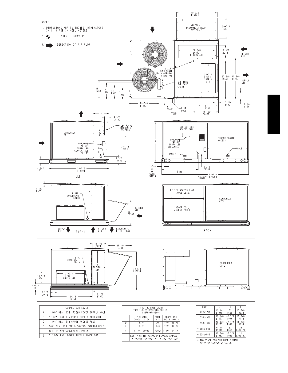
Fig. 1 -- Unit Dimensional Drawing – 08, 09 and 12 Size Units
Horizontal Connections / Economizer
C08609
3
558J***D
C08610
Fig. 1 -- Unit Dimensional Drawing – 08, 09 and 12 Size Unit (cont.)
4
Vertical Connections / Economizer
558J***D
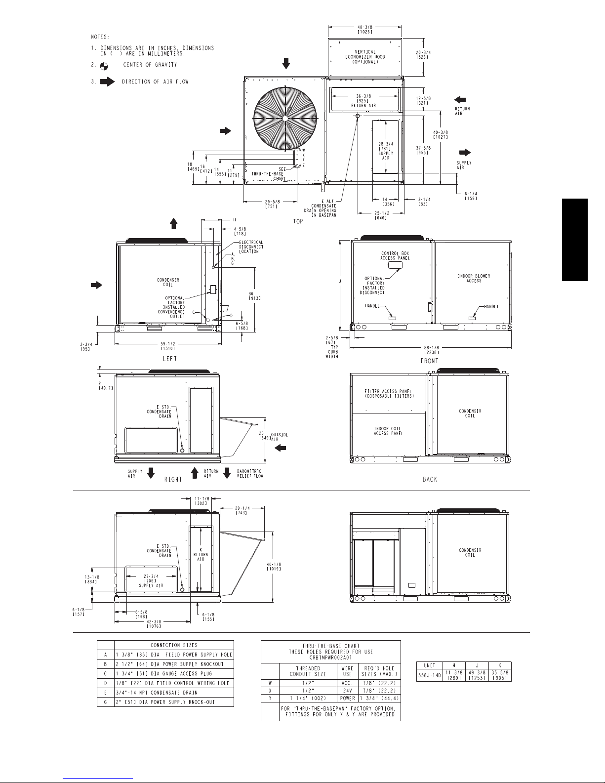
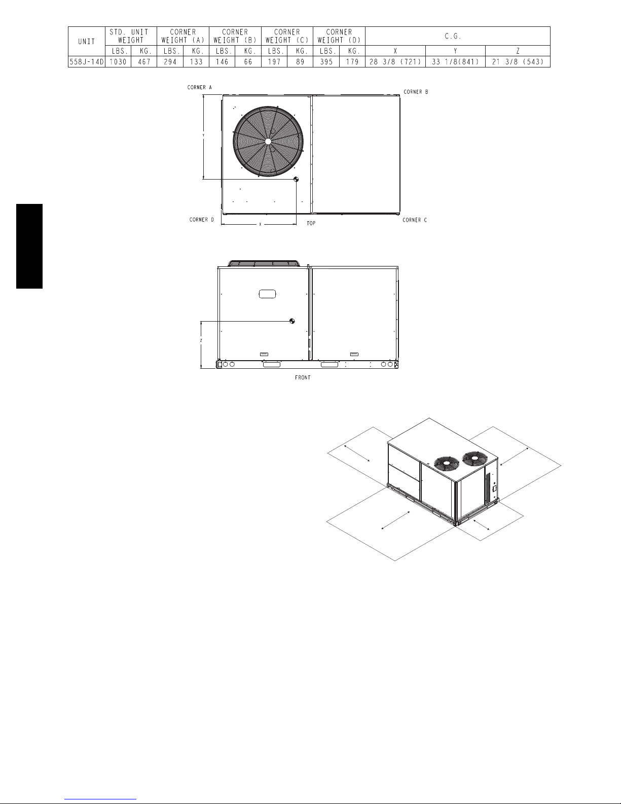
Fig. 2 -- Unit Dimensional Drawing – 14 Size Unit
Horizontal Connections / Economizer
C08611
5
558J***D
Jobsite Survey
Fig. 2 -- Unit Dimensional Drawing – 14 Size Unit (cont.)
INSTALLATION
18” (457)
C08606
1
Complete the following checks before installation.
1. Consult local building codes and the NEC (National
Electrical Code) ANSI/NFPA 70 for special installation requirements.
2. Determine unit location (from project plans) or select
unit location.
3. Check for possible overhead obstructions which may
interfere with unit lifting or rigging.
Step 1 — Plan for Unit Location
Select a location for the unit and its support system (curb
or other) that provides for the minimum clearances
required for safety. This includes the clearance to
combustible surfaces, unit performance and service access
below, around and above unit as specified in unit
drawings. See Fig. 3.
NOTE: Consider also the effect of adjacent units.
Do not install unit in an indoor location. Do not locate air
inlets near exhaust vents or other sources of contaminated
air.
Although unit is weatherproof, avoid locations that permit
water from higher level runoff and overhangs to fall onto
the unit.
42" (1067)
42" (1067)
1
Required bottom condensate drain connection.
Otherwise, 36” (914mm) for condensate connection.
18" (457)
C07459
Fig. 3 -- Service Clearance Dimensional Drawing
Unit may be installed directly on wood flooring or on
Class A, B, or C roof--covering material when roof curb is
used.
Select a unit mounting system that provides adequate
height to allow installation of condensate trap per
requirements.RefertoStep9—InstallExternal
Condensate Trap and Line – for required trap dimensions.
Roof mount —
Check building codes for weight distribution
requirements. Unit operating weight is shown in Table 1.
6

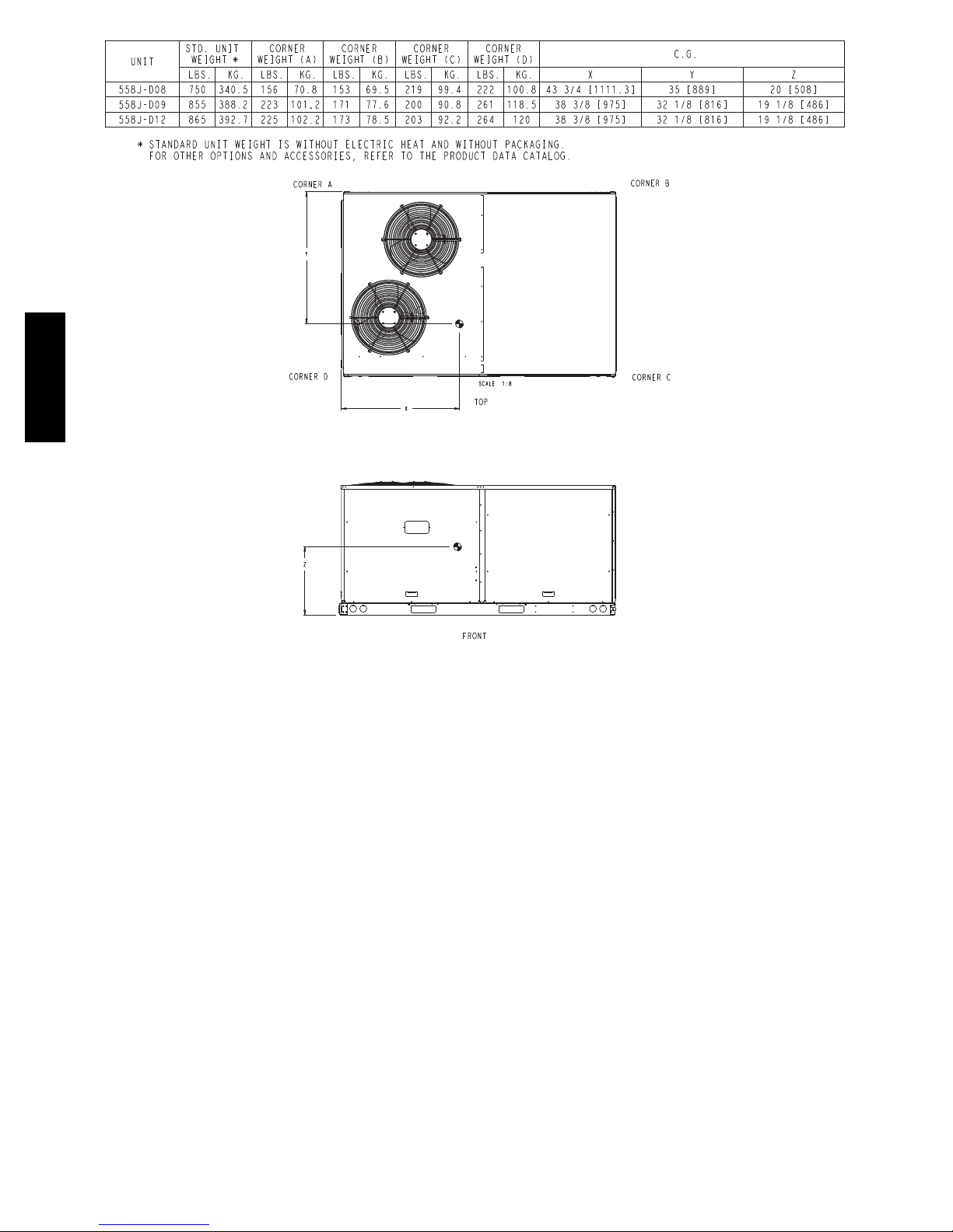
Table 1 – Operating Weights
558J***D UNITS LB (KG)
Component 08D 09D 12D 14D
Base Unit 750 (340.5) 855 (388.2) 865 (385) 1030 (467)
Economizer
Vertical 80 (36) 80 (36) 80 (36) 80 (36)
Horizontal 105 (48) 105 (48) 105 (48) 105 (48)
Perfect Humidity™ System 70 (32) 70 (32) 75 (34) —
Powered Outlet 32 (15) 32 (15) 32 (15) 32 (15)
Curb
14--- in/356 mm 133 (60) 133 (60) 133 (60) 133 (60)
24--- in/610 mm 174 (79) 174 (79) 174 (79) 174 (79)
Step 2 — Plan for Sequence of Unit Installation
The support method used for this unit will dictate different
sequences for the steps of unit installation. For example,
on curb--mounted units, some accessories must be
installed on the unit before the unit is placed on the curb.
Review the following for recommended sequences for
installation steps.
Curb--mounted installation —
Install curb
Install field--fabricated ductwork inside curb
Install accessory thru--base service connection package
(affects curb and unit) (refer to accessory installation
instructions for details)
Prepare bottom condensate drain connection to suit
planned condensate line routing (refer to Step 9 for
details)
Rig and place unit
Install outdoor air hood
Install condensate line trap and piping
Make electrical connections
Install other accessories
Pad--mounted installation —
Prepare pad and unit supports
Check and tighten the bottom condensate drain
connection plug
Rig and place unit
Convert unit to side duct connection arrangement
Install field--fabricated ductwork at unit duct openings
Install outdoor air hood
Install condensate line trap and piping
Make electrical connections
Install other accessories
Frame--mounted installation —
Frame--mounted applications generally follow the
sequence for a curb installation. Adapt as required to
suit specific installation plan.
Step 3 — Inspect unit
Inspect unit for transportation damage. File any claim
with transportation agency.
Confirm before installation of unit that voltage, amperage
and circuit protection requirements listed on unit data
plate agree with power supply provided.
Step 4 — Provide Unit Support
Roof Curb Mount —
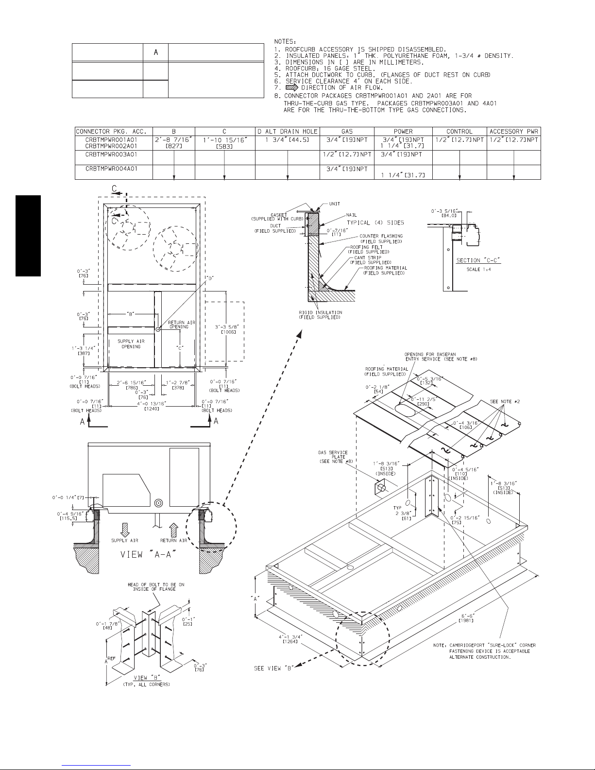
Accessory roof curb details and dimensions are shown in
Fig. 4. Assemble and install accessory roof curb in
accordance with instructions shipped with the curb.
NOTE: The gasketing of the unit to the roof curb is
critical for a watertight seal. Install gasket supplied with
the roof curb as shown in Fig. 4. Improperly applied
gasket can also result in air leaks and poor unit
performance.
Curb should be level. This is necessary for unit drain to
function properly. Unit leveling tolerances are show in
Fig. 5. Refer to Accessory Roof Curb Installation
Instructions for additional information as required.
Install insulation, cant strips, roofing felt, and counter
flashing as shown. Ductwork must be attached to curb and
not to the unit. The accessory thru--the--base power
package must be installed before the unit is set on the roof
curb.
If electric and control wiring is to be routed through the
basepan, attach the accessory thru--the--base service
connections to the basepan in accordance with the
accessory installation instructions.
Slab Mount (Horizontal Units Only) —
Provide a level concrete slab that extends a minimum of 6
in. (150 mm) beyond unit cabinet. Install a gravel apron in
front of condenser coil air inlet to prevent grass and
foliage from obstructing airflow.
NOTE: Horizontal units may be installed on a roof curb
if required.
Alternate Unit Support (In Lieu of Curb or Slab
Mount) —
A non--combustible sleeper rail can be used in the unit
curb support area. If sleeper rails cannot be used, support
the long sides of the unit with a minimum of 3 equally
spaced 4--in. x 4--in. (102 mm x 102 mm) pads on each
side.
558J***D
7
558J*08 -
14D
ROOFCURB
UNIT SIZE
ACCESSORY
CRRFCURB003A01
CRRFCURB004A01
1’ - 2”
(356)
2’ - 0”
(610)
UNIT SIZE
558J*08 -
14D
558J***D
C08504
Fig. 4 -- Roof Curb Details
8

MAXIMUM ALLOWABLE
DIFFERENCE IN. (MM)
A-B
0.5” (13)
1.0” (25)
Fig. 5 -- Unit Leveling Tolerances
Step 5 — Field Fabricate Ductwork
B-C
A-C
1.0” (25)
C06110
should be ducted through the roof deck to comply with
applicable fire codes.
For units with accessory electric heaters: Horizontal
applications require a minimum clearance to combustibl8
surfaces of 1--in (25 mm) from duct for first 12--in (305 mm)
away from unit. Vertical applications do not require a
minimum clearance.
Minimum clearance is not required around ductwork.
Step 6 — Rig and Place Unit
Keep unit upright and do not drop. Spreader bars are not
required if top crating is left on unit. Rollers may be used
to move unit across a roof. Level by using unit frame as a
reference. See Table 1 and Fig. 6 for additional information.
Cabinet return-air static pressure (a negative condition)
shall not exceed 0.35 in. wg (87 Pa) with economizer or
0.45 in. wg (112 Pa) without economizer.
For vertical ducted applications, secure all ducts to roof curb
and building structure. Do not connect ductwork to unit.
Insulate and weatherproof all external ductwork, joints,
and roof openings with counter flashing and mastic in
accordance with applicable codes.
Ducts passing through unconditioned spaces must be
insulated and covered with a vapor barrier.
If a plenum return is used on a vertical unit, the return
Lifting holes are provided in base rails as shown in Fig. 6.
Refer to rigging instructions on unit.
!
CAUTION
UNIT DAMAGE HAZARD
Failure to follow this caution may result in
equipment damage.
All panels must be in place when rigging. Unit is not
designed for handling by fork truck.
Before setting the unit onto the curb, recheck gasketing on
curb.
558J***D
UNIT
558J*08D 1410 641 88.0 2235 41.0 1040 41.5 1055
558J*09D 1525 693 88.0 2235 40.5 1030 49.5 1255
558J*12D 1565 711 88.0 2235 40.0 1015 49.5 1255
558J*14D 1720 782 88.0 2235 28.5 725 53.0 1345
NOTES:
1. Dimensions in ( ) are in millimeters.
2. Hook rigging shackles through holes in base rail, as shown in detail “A.” Holes in base rails are centered around the
unit center of gravity. Use wooden top to prevent rigging straps from damaging unit.
MAX WEIGHT
LB KG IN MM IN MM IN MM
C06005
DIMENSIONS
A B C
Fig. 6 -- Rigging Details
9
PositioningonCurb—
Position unit on roof curb so that the following clearances
are maintained:
1
/4in. (6.4 mm) clearance between the
roof curb and the base rail inside the front and back, 0.0
in. clearance between the roof curb and the base rail
inside on the duct end of the unit. This will result in the
distance between the roof curb and the base rail inside on
the condenser end of the unit being approximately equal
to Fig. 4, section C--C.
Although unit is weatherproof, guard against water from
higher level runoff and overhangs.
After unit is in position, remove rigging skids and
shipping materials.
Step 7 — Convert to Horizontal and Connect
Ductwork (when required)
Unit is shipped in the vertical duct configuration. Unit
without factory--installed economizer or return air smoke
558J***D
detector option may be field--converted to horizontal
ducted configuration. To convert to horizontal
configuration, remove screws from side duct opening
covers and remove covers. Using the same screws, install
covers on vertical duct openings with the insulation--side
down. Seals around duct openings must be tight. See
Fig. 7.
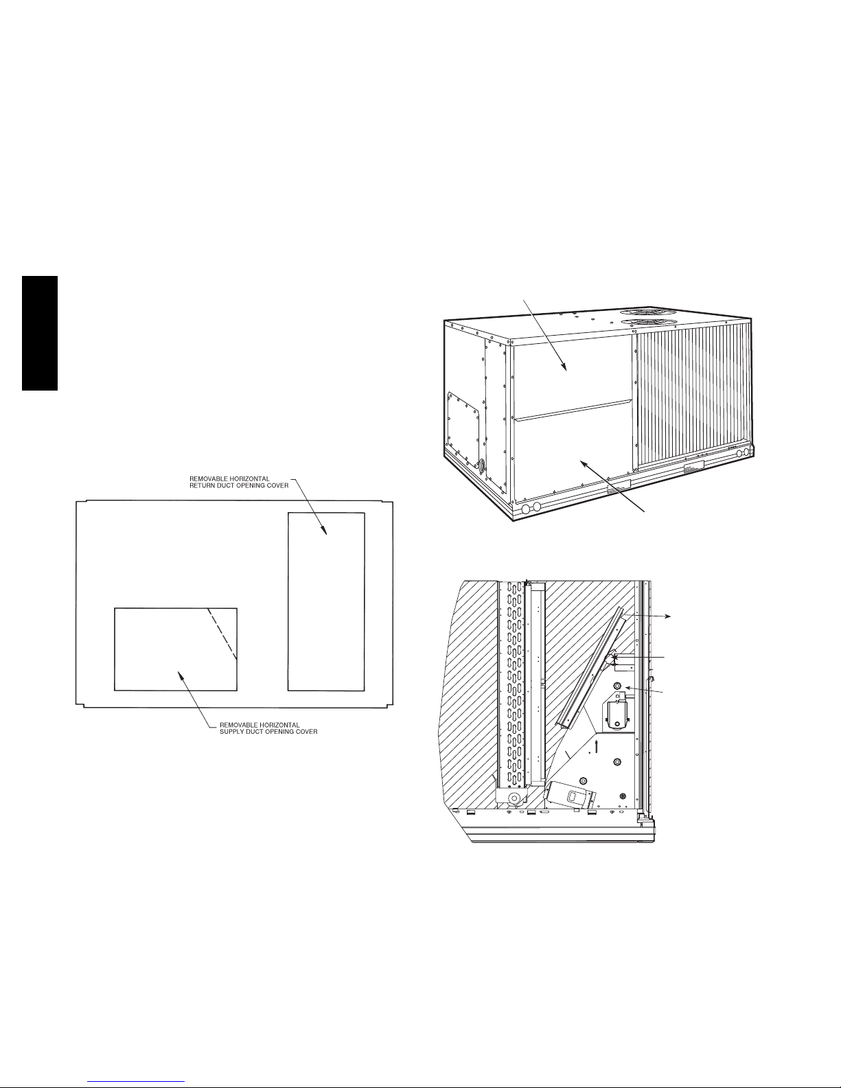
Step 8 — Install Outside Air Hood
Economizer Hood Removal and Setup -- Factory
Option
1. The hood is shipped in knock--down form and
located in the return air compartment. It is attached
to the economizer using two plastic tie--wraps.
2. To gain access to the hood, remove the filter access
panel. (See Fig. 8.)
3. Locate and cut the (2) plastic tie--wraps, being
careful to not damage any wiring. (See Fig. 9.)
4. Carefully lift the hood assembly through the filter
access opening and assemble per the steps outlined
in Economizer Hood and Two–Position Hood on
page 12.
FILTER ACCESS PANEL
C06108
Fig. 7 -- Horizontal Conversion Panels
Field--supplied flanges should be attached to horizontal
duct openings and all ductwork should be secured to the
flanges. Insulate and weatherproof all external ductwork,
joints, and roof or building openings with counter flashing
and mastic in accordance with applicable codes.
Do not cover or obscure visibility to the unit’s informative
data plate when insulating horizontal ductwork.
INDOOR COIL ACCESS PANEL
C06023
Fig. 8 -- Typical Access Panel Locations
Remove Hood Parts
Cut Plastic Ties
(2) Places
Economizer
C08633
Fig. 9 -- Economizer Wiring
10
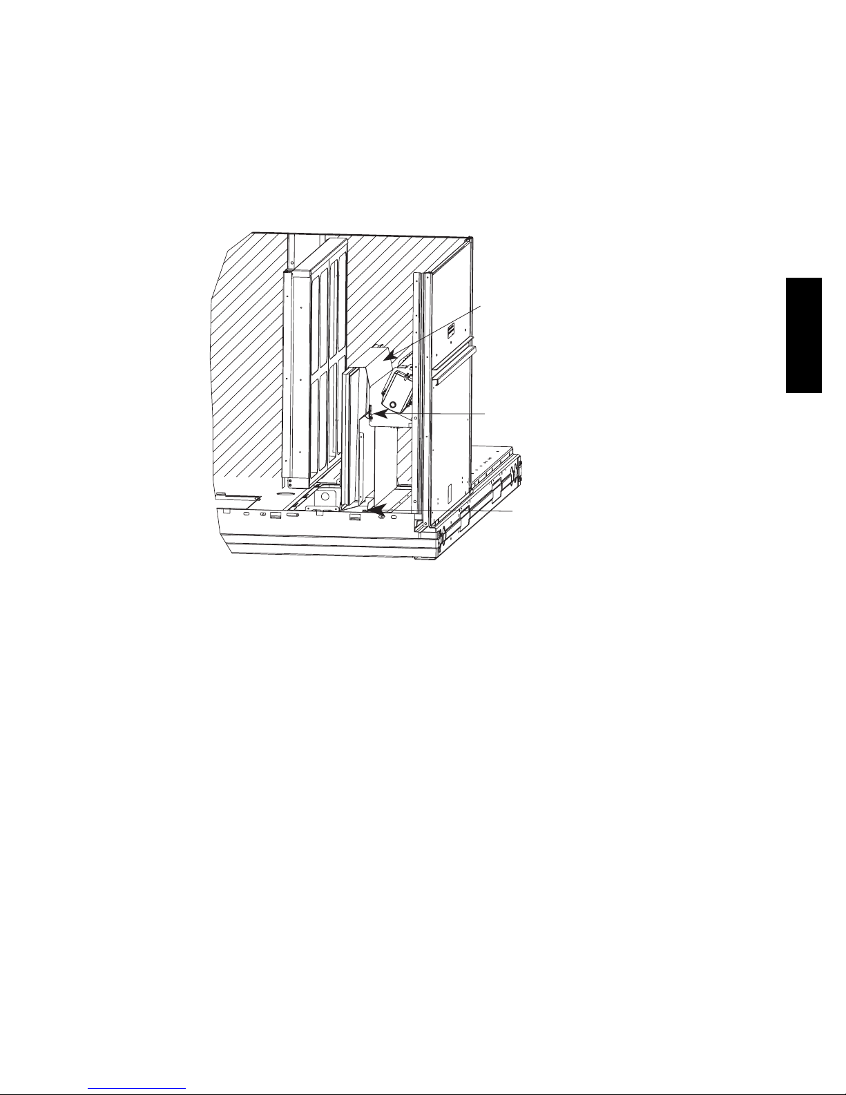
Two Position Damper Hood Removal and Setup -Factory Option
1. The hood is shipped in knock--down form and
assembled to a metal support tray using plastic
stretch wrap. Located in the return air
compartment, the assembly’s metal tray is attached
to the basepan and also attached to the damper
using two plastic tie--wraps.
2. To gain access to the hood, remove the filter access
panel. (See Fig. 8.)
3. Locate the (2) screws holding the metal tray to the
basepan and remove. Locate and cut the (2) plastic
tie--wraps securing the assembly to the damper. (See
Fig. 10.) Be careful to not damage any wiring or cut
tie--wraps securing any wiring.
4. Carefully lift the hood assembly (with metal tray)
through the filter access opening and assemble per
the steps outlined in Economizer Hood and
Two–Position Hood on page 12.
Hood Parts
558J***D
Plastic Tie Wrap
Qty (2)
Fig. 10 -- Damper Assembly
Screws for Metal Tray
Qty (2)
C08639
11
Economizer Hood and Two--Position Hood —
NOTE: If the power exhaust accessory is to be installed
on the unit, the hood shipped with the unit will not be
used and must be discarded. Save the aluminum filter for
use in the power exhaust hood assembly.
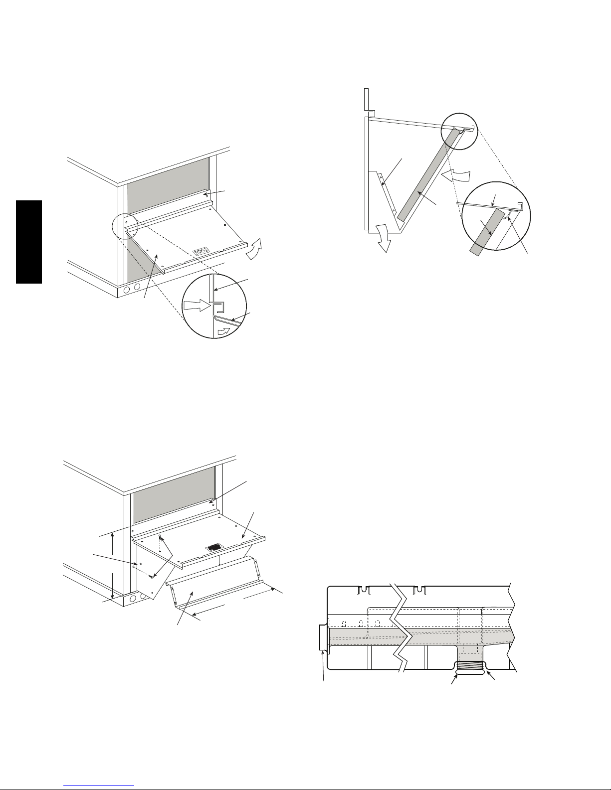
1. The indoor coil access panel will be used as the top of
the hood. Remove the screws along the sides and bottom of the indoor coil access panel. See Fig. 11.
5. Open the filter clips which are located underneath the
hood top. Insert the aluminum filter into the bottom
filter rack (hood divider). Push the filter into position
past the open filter clips. Close the filter clips to lock
the filter into place. See Fig. 13.
DIVIDER
OUTSIDE
AIR
558J***D
CAULK
INDOOR
COIL
ACCESS
PANEL
HERE
Fig. 11 -- Indoor Coil Access Panel Relocation
2. Swing out indoor coil access panel and insert the
hood sides under the panel (hood top). Use the screws
provided to attach the hood sides to the hood top. Use
screws provided to attach the hood sides to the unit.
See Fig. 12.
LEFT
HOOD
SIDE
19 1/16”
B
(483mm)
SCREW
TOP
PANEL
TOP
PANEL
INDOOR
COIL
ACCESS
PANEL
TOP
PANEL
INDOOR COIL
ACCESS PANEL
C06025
HOOD
CLEANABLE
BAROMETRIC
RELIEF
ALUMINUM
FILTER
FILTER
FILTER
CLIP
C08634
Fig. 13 -- Economizer Filter Installation
6. Caulk the ends of the joint between the unit top panel
and the hood top.
7. Replace the filter access panel.
Step 9 — Install External Condensate Trap and
Line
The unit has one3/4-in. condensate drain connection on
the end of the condensate pan and an alternate connection
on the bottom. See Fig. 14. Unit airflow configuration
does not determine which drain connection to use. Either
drain connection can be used with vertical or horizontal
applications.
When using the standard side drain connection, ensure the
red plug in the alternate bottom connection is tight. Do
this before setting the unit in place. The red drain pan can
be tightened with a
To use the alternate bottom drain connection, remove the
red drain plug from the bottom connection (use a1/2-- i n .
square socket drive extension) and install it in the side
drain connection.
1
/2--in. square socket drive extension.
HOOD DIVIDER
Fig. 12 -- Economizer Hood Construction
3. Remove the shipping tape holding the economizer barometric relief damper in place.
4. Insert the hood divider between the hood sides. See
Fig. 12 and 13. Secure hood divider with 2 screws on
each hood side. The hood divider is also used as the
bottom filter rack for the aluminum filter.
33 3/8”
(848mm)
C06026
CONDENSATE PAN (SIDE VIEW)
STANDARD
SIDE DRAIN
DRAIN
PLUG
(FACTORY-INSTALLED)
Fig. 14 -- Condensate Drain Pan (Side View)
12
ALTERNATE
BOTTOM DRAIN
C08021
 Loading...