

Page 1
wiring diagrams
A
A
C
C
C
C
C
G
SINGLE PACKAGE ROOFTOP
ELECTRIC COOLING
UNITS
Cancels: New WD 558F.36.1
DIAGRAM INDEX
UNIT LABEL DIAGRAM
Unit 558F Voltage-Phase-Hertz Type Label Diagram Figure No.
208/230-1-60 Schematic/Component Arrangement 50DK508524 1
036,048
060
072
090-150
208/230-3-60 Schematic/Component Arrangement 50DK508526 2
460-3-60 Schematic/Component Arrangement 50DK508529 3
575-3-60 Schematic/Component Arrangement 50DK508531 4
208/230-1-60 Schematic/Component Arrangement 50DK508525 5
208/230-3-60 Schematic/Component Arrangement 50DK508527 6
460-3-60 Schematic/Component Arrangement 50DK508530 7
575-3-60 Schematic/Component Arrangement 50DK508532 8
208/230-3-60, 460-3-60 Schematic/Component Arrangement 50DK508528 9
575-3-60 Schematic/Component Arrangement 50DK508533 10
208/230-3-60, 460-3-60 Schematic/Component Arrangement 50DK508793 11
575-3-60 Schematic/Component Arrangement 50DK508794 12
3 to 121/2 Tons
558F
036-150
11/15/00
ACCESSORY WIRING
Description Unit Size Fig. No.
Motormaster® I Control 036-150 13
Motormaster II Control
Time Guard® II Device 036-150 16
Solid-State Enthalpy Control 036-150 17
Differential Enthalpy Control 036-150 18
EconoMi$er 036-072 19
EconoMi$er Sensor Wiring 036-150 20
Power Exhaust 036-072 21
036-072 14
090-150 15
LEGEND
HA — Adjustable Heat Anticipator
WG — American Wire Gage
— Contactor, Compressor
AP. — Capacitor
B—Circuit Breaker
C—Cooling Compensator
OMP — Compressor Motor
D—Diode
EC — Enthalpy Control
ECON — Economizer
EPS — Emergency Power Supply
EQUIP — Equipment
ER — Economizer Relay
FPT — Freeze-Up Protection Thermostat
FU — Fuse
ND — Ground
HC — Heater Contactor (Strip Heat)
HPS — High-Pressure Switch
IFC — Indoor-Fan Contactor
IFM — Indoor-Fan Motor
IFMOVL— Indoor-Fan Motor Overload
(Nine-Volt Battery)
IFR — Indoor-Fan Relay
LPS — Low-Pressure Switch
LSM — Limit Switch (Manual Reset)
MTR — Motor
OAT — Outdoor-Air Thermostat
OFC — Outdoor-Fan Contactor
OFM — Outdoor-Fan Motor
OLR — Overload Relay
P—Plug
PL — Plug Assembly
QT — Quadruple Terminal
R—Relay
SAT — Supply-Air Thermostat
SEN — Sensor
ST — Start Thermistor
SW1 — Switch Fully Open
SW2 — Switch Fully Closed
SW3 — Switch Minimum Vent Position
SW4 — Switch Maximum Vent Position
TB — Terminal Block
TC — Thermostat, Cooling
TDR — Time-Delay Relay
TH — Thermostat, Heating
TRAN — Transformer
Field Splice
Marked Wire
Terminal (Marked)
Terminal (Unmarked)
Terminal Block
Splice
Splice (Marked)
Factory Wiring
Field Control Wiring
Field Power Wiring
Accessory or Optional Wiring
To indicate common potential only.
Not to represent wiring.
Page 2
NOTES FOR FIG. 1, 2, 5, 6, 9
1. If any of the original wire furnished must be replaced, it must be
replaced with Type 90 C wire or its equivalent.
2. Three-phase motors are protected under primary single-phasing
conditions.
3. Thermostat:
HH07AT170, 172, 174, and P272-2783
Subbase:
HH93AZ176, 178, and P272-1882, 1883
NOTES FOR FIG. 3, 4, 7, 8, 10
1. If any of the original wire furnished must be replaced, it must be
replaced with Type 90 C wire or its equivalent.
2. Three-phase motors are protected under primary single-phasing
conditions.
3. Thermostat:
HH07AT170, 172, 174, and P272-2783
Subbase:
HH93AZ176, 178, and P272-1882, 1883
NOTES FOR FIG. 11
1. If any of the original wire furnished must be replaced, it must be
replaced with Type 90 C wire or its equivalent.
2. Three-phase motors are protected under primary single-phasing
conditions.
3. Thermostat:
HH07AT170, 172, 174, and P272-2783
Subbase:
HH93AZ176, 178, and P272-1882, 1883
4. Set heat anticipator at 1 amp.
5. Use copper conductors only.
6. Use copper, copper-clad aluminum or aluminum conductors.
4. Set heat anticipator at 1 amp.
5. Use copper conductors only.
6. Use copper, copper-clad aluminum or aluminum conductors.
7. For 208/230-3-60 v units: TRAN is wired for 230-v unit. If unit is to be
run with 208-v power supply, disconnect BLK wire from 230-v tap
(RED) and connect to 208-v tap (BLU). Insulate end of 230-v tap.
8.
CIRCUIT
BREAKER
CB 24 V
CB1 150 460-3-60
VOLTS MFG. PT. NO.
Potter & Brumfield
Heinemann Airpax
MUST
TRIP
AMPS
3.2W2BX-1024-3.2
8.5CF3-Z228-4 219-3-2600-486
NOTES FOR FIG. 12
1. If any of the original wire furnished must be replaced, it must be
replaced with Type 90 C wire or its equivalent.
2. Three-phase motors are protected under primary single-phasing
conditions.
3. Thermostat:
HH07AT170, 172, 174, and P272-2783
Subbase:
HH93AZ176, 178, and P272-1882, 1883
4. Set heat anticipator at 1 amp.
5. Use copper conductors only.
6. Use copper, copper-clad aluminum or aluminum conductors.
7.
CIRCUIT
BREAKER
CB 24 V
CB1 150 460-3-60
VOLTS MFG. PT. NO.
Potter & Brumfield
Heinemann Airpax
MUST
TRIP
AMPS
3.2W2BX-1024-3.2
8.5CF3-Z228-4 219-3-2600-486
—2—
Page 3
—3—
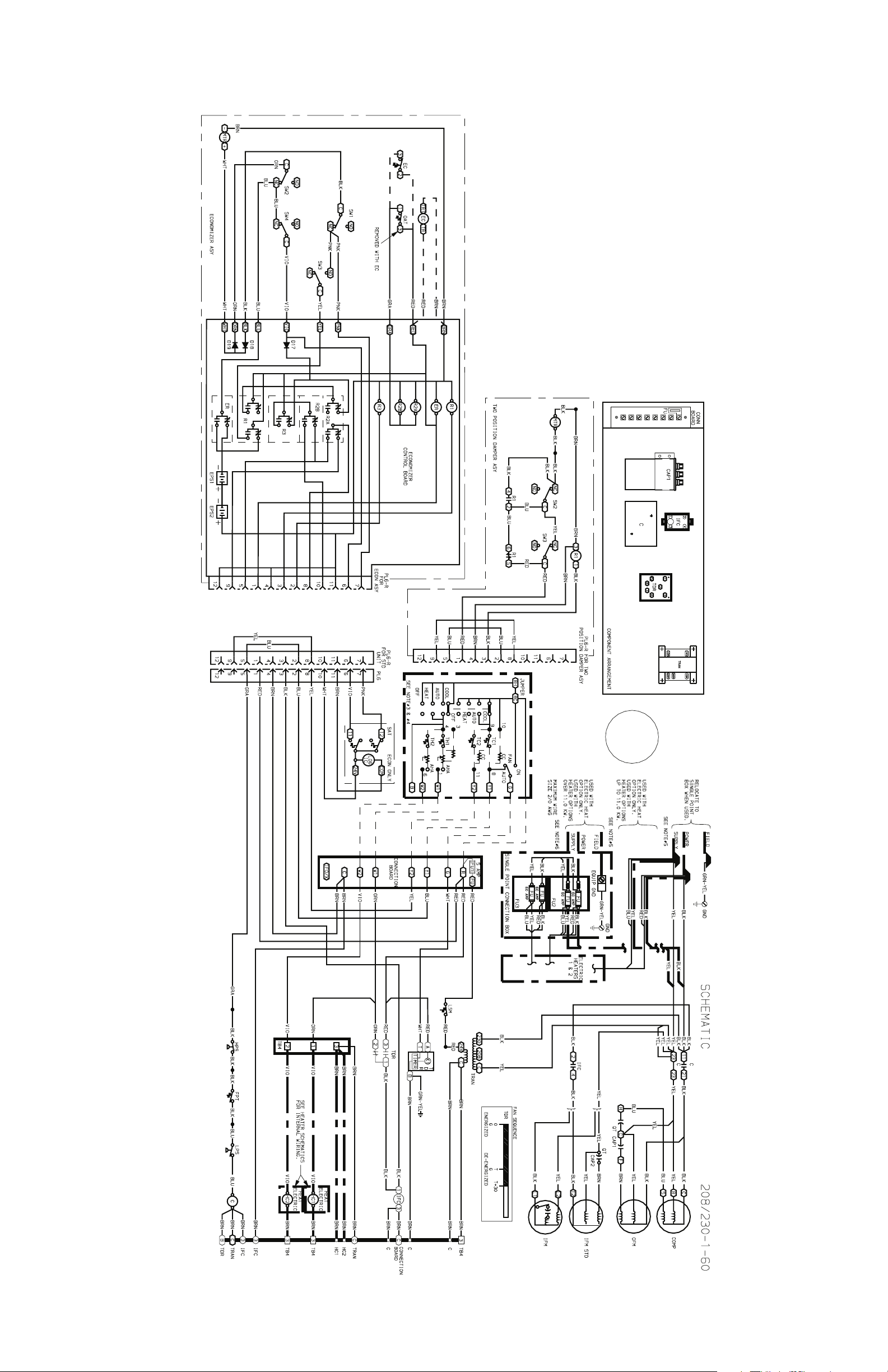
Fig. 1 — Schematic/Component Arrangement; 558F036,048; 208/230-1-60
Page 4
—4—
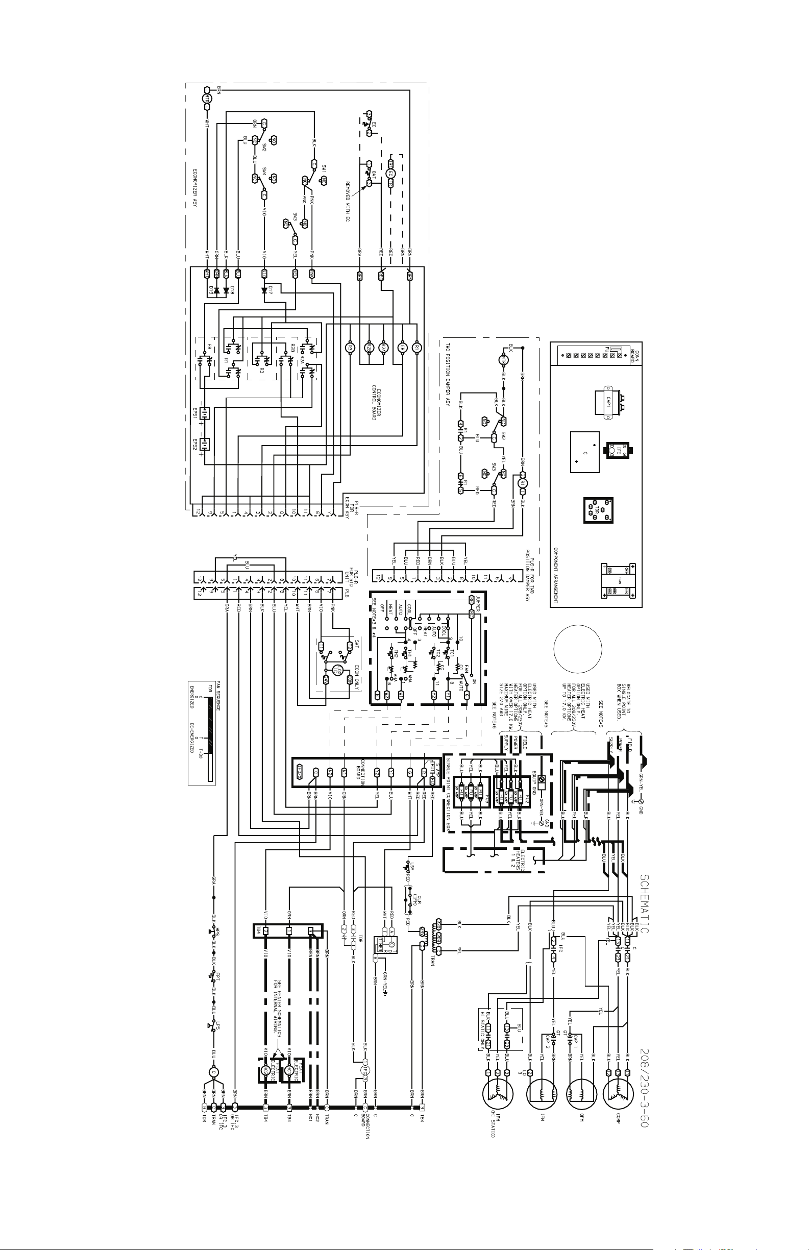
Fig. 2 — Schematic/Component Arrangement; 558F036,048; 208/230-3-60
Page 5
—5—
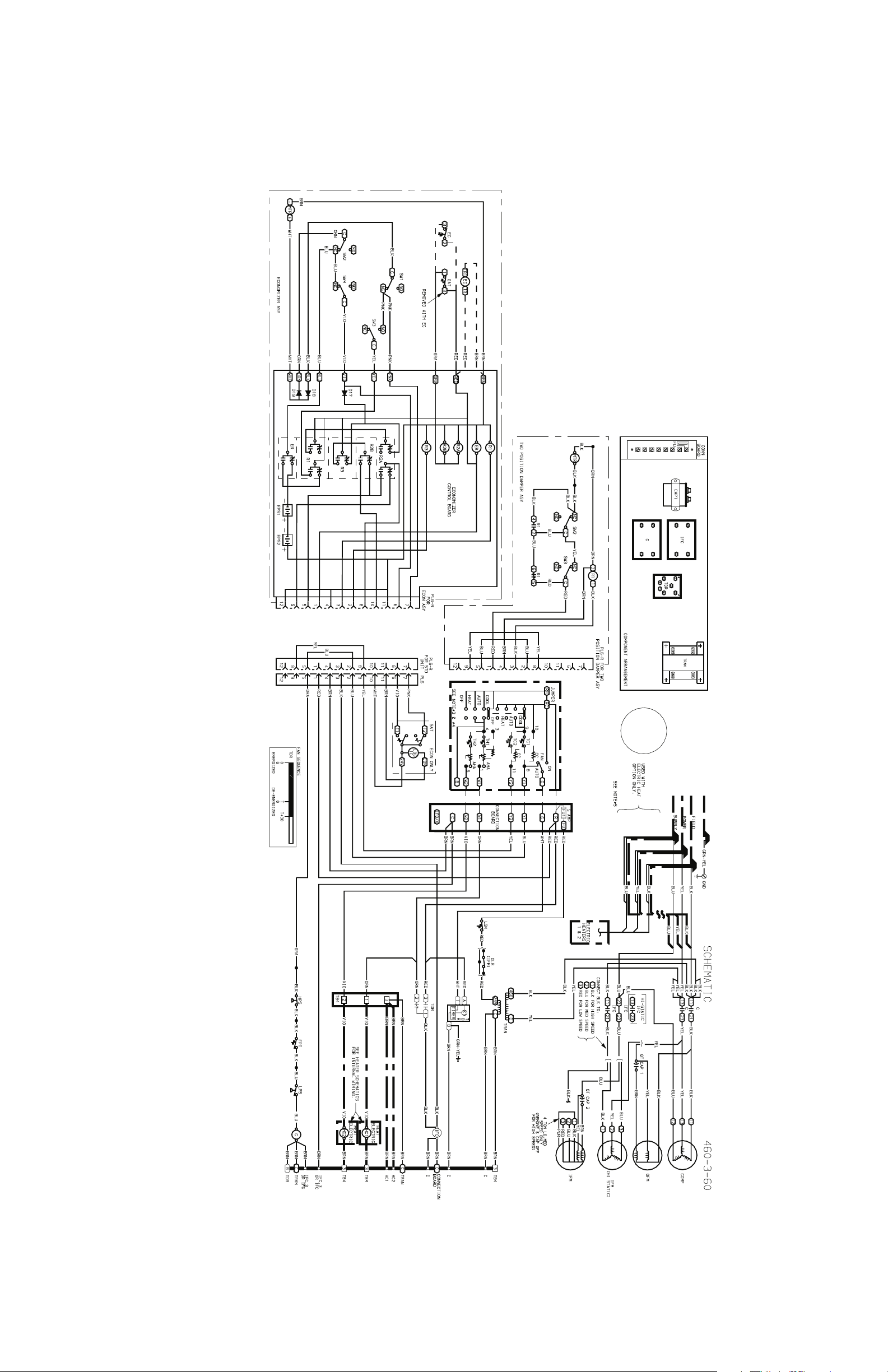
Fig. 3 — Schematic/Component Arrangement; 558F036,048; 460-3-60
Page 6
—6—
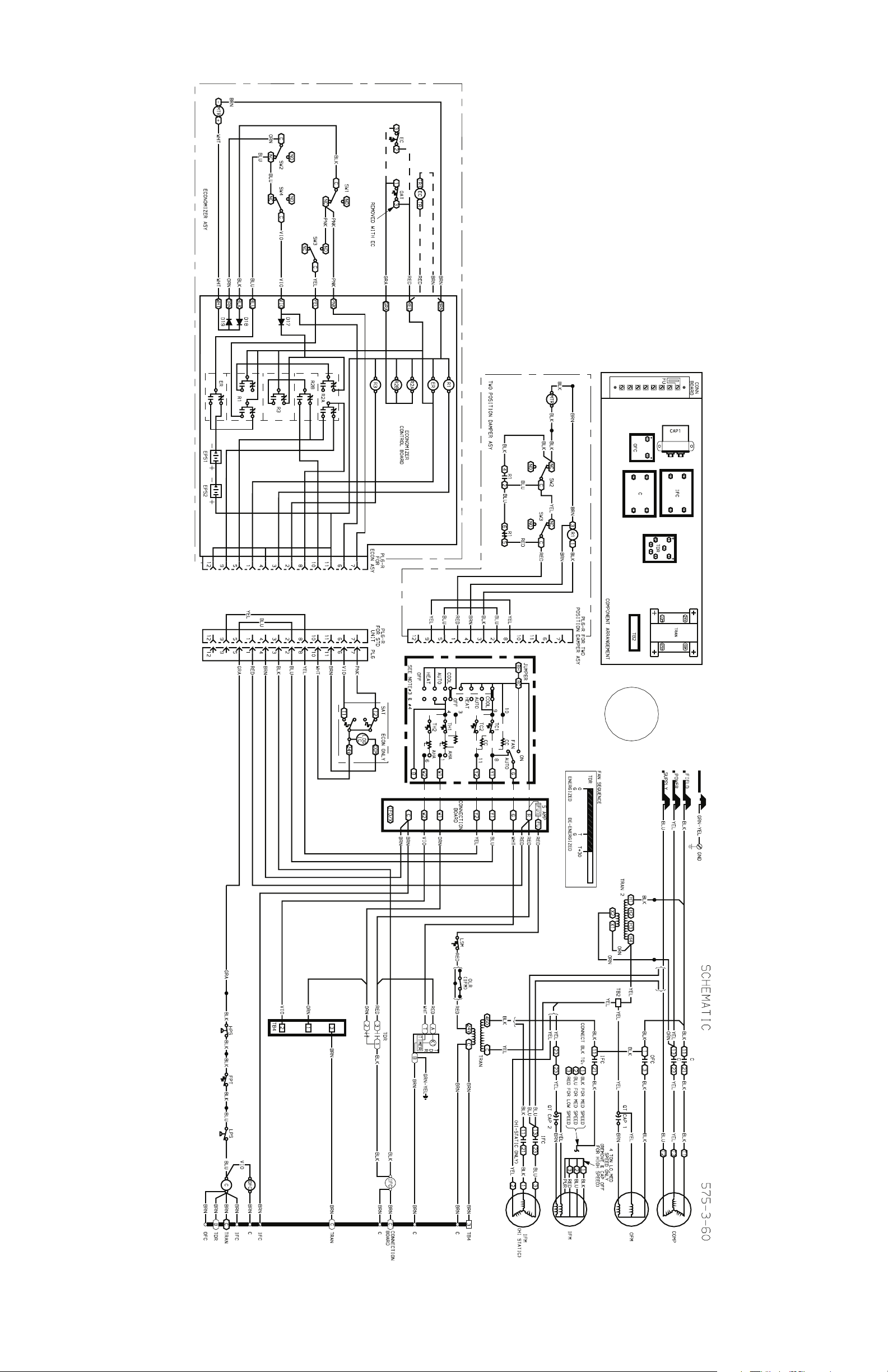
Fig. 4 — Schematic/Component Arrangement; 558F036,048; 575-3-60
Page 7

—7—
Fig. 5 — Schematic/Component Arrangement; 558F060; 208/230-1-60
Page 8

—8—
Fig. 6 — Schematic/Component Arrangement; 558F060; 208/230-3-60
Page 9

—9—
Fig. 7 — Schematic/Component Arrangement; 558F060; 460-3-60
Page 10

—10—
Fig. 8 — Schematic/Component Arrangement; 558F060; 575-3-60
Page 11

—11—
Fig. 9 — Schematic/Component Arrangement; 558F072; 208/230-3-60 and 460-3-60
Page 12

—12—
Fig. 10 — Schematic/Component Arrangement; 558F072; 575-3-60
Page 13

—13—
Fig. 11 — Schematic/Component Arrangement; 558F090-150; 208/230-3-60 and 460-3-60
Page 14

—14—
Fig. 12 — Schematic/Component Arrangement; 558F090-150; 575-3-60
Page 15

LEGEND
C — Contactor
558F036-072
558F090-150
Fig. 13 — Motormaster® I Wiring Details
LEGEND
C—Contactor
OFC — Outdoor-Fan Contactor
TRAN — Transformer
NOTE: Motormaster II transformer is wired for 460-v supply; it must be rewired for 208/230-v application.
Be sure to insulate unused tap. Refer to color code.
Fig. 14 — Motormaster II Wiring Schematic; 558F036-072
—15—
Page 16

LEGEND
C—Contactor
OFC — Outdoor-Fan Contactor
TRAN — Transformer
*The Motormaster II head pressure controller is equipped with an alternate operating mode. When
this mode is selected, the controller shifts the fan cycle sequence to effectively raise the average
condensing temperature approximately 20 F higher than the standard operating mode. In this
alternate mode, the outdoor fan begins cycling at higher outdoor ambient temperatures. This
mode should only be used if the evaporator coil shows signs of frosting at low outdoor ambient
temperatures.
To select the alternate operating mode, move the jumper wire on the Motormaster II control board
from reset T1 to reset T2.
NOTE: Motormaster® II transformer is wired for 460-v supply; it must be rewired for 208/230-v
application. Be sure to insulate unused tap. Refer to color code.
Fig. 15 — Motormaster II Wiring Schematic; 558F090-150
—16—
Page 17

TIME GUARD I I DEVICE
BRN
BRN
LEGEND
C — Contactor
CLO — Compressor Lockout
CR — Control Relay
T1
T3
T2
2
1
CLO
3
COMPRESSOR
SAFETIES
HIGH EFFICIENCY 3 TO 121/2 TON ROOFTOP UNITS
TIME GUARD I I DEVICE
T3
T2
OR
CR
C
T1
STANDARD EFFICIENCY 3 TO 121/2 TON ROOFTOP UNITS
Fig. 16 — Time Guard® II Device; 558F036-150
BRN
OR
CR
C
24 VAC SUPPLY FROM
ECONOMIZER CONTROL
}
TR1
TR
B
A
C
SO +
D
+
SR
3
2
1
LED
NOTE: Switches shown in high enthalpy state. Terminals 2 and 3
close on enthalpy decrease.
SECTION (RED TO TR,
BRN TO TR1)
TO SENSOR MOUNTED
}
ON BACK OF CONTROL
620 ohm
JUMPER
GRAY WIRE FROM
ECONOMIZER HARNESS
RED WIRE FROM
ECONOMIZER SWITCH 3
(NORMALLY CLOSED)
Fig. 17 — Wiring Connections for Solid-State
Enthalpy Control (HH57AC077)
24 VAC SUPPLY FROM
ECONOMIZER CONTROL
SECTION (RED TO TR,
BRN TO TR1)
TO SENSOR MOUNTED
ON BACK OF CONTROL
S
(HH57AC078
SENSOR)
+
GRAY WIRE FROM
ECONOMIZER HARNESS
RED WIRE FROM
ECONOMIZER SWITCH 3
(NORMALLY CLOSED)
A
B
LED
C
D
SO
SR
TR TR1
2
+
+
3
1
NOTES:
1. Remove factory-installed jumper across SR and + before connecting wires from HH57AC078 sensor.
2. Switches shown in high outdoor-air enthalpy state. Terminals 2
and 3 close on low outdoor air enthalpy relative to indoor air
enthalpy.
Fig. 18 — Wiring Connections for Differential
Enthalpy Control (HH57AC077 and HH57AC078)
—17—
Page 18

LEGEND
OAT — Outdoor-Air Thermostat
Fig. 19 — EconoMi$er Wiring
ECONOMI$ER
CONTROLLER
OAT
COM
OAH
-15 V
RAT
COM
RAH
+15 V
(+)
CO
2
CO
COM
2
DAT
COM
REM POT
COM
LED
COM
Fig. 20 — EconoMi$er Sensor Wiring; 558F036-150
BROWN
VIOLET
WHITE
RED
BROWN
VIOLET
WHITE
RED
SUPPLY AIR
TEMPERATURE SENSOR
PINK
VIOLET
TEMP
TEMP
—18—
TEMP
TEMP
COM
OUT
PWR
TEMP
TEMP
COM
OUT
PWR
CO
SENSOR
2
24
V+
COM VAC
OUTDOOR
AIR
SENSOR
RETURN
AIR
SENSOR
Page 19

TO FUSED
DISCONNECT
RED
H1
(575 VAC)
HT01AH859
X4
HANDY BOX
X2
X3
SECONDARY
230VAC
2 x 4 IN.
GRAY
H2
X1
GREEN GND
OR
BLACK L1
BLUE L2
RED YELH1BLU
(460 VAC)
HT01AH850
X4
COMPRESSOR 1
CONTACTOR
11 21
13
CONNECTOR
L1
1
1
L2
22
GND
33
44
230 VAC
1 PHASE
H3
H2
X3
X2
SECONDARY
230VAC
230VAC
23
4-PIN
PLUG
GREEN
GRAY
H4
X1
BLACK
BLUE
FIELD SUPPLIED
WIRING
BROWN
C1
GREEN/
YELLOW
BROWN
C1
GREEN/
YELLOW
FAN 1
FAN 2
BLACK
BLACK
LT. BLUE
BLACK
BLUE
BLACK
LT. BLUE
BLACK
3
2
1
3
2
1
6
5
4
6
5
4
BLUE
B
9
8
7
9
8
7
R1
24 VAC
A
B
R2
24 VAC
A
3-PIN
CONNECTOR
PLUG
ORANGE
YELLOW
BROWN
1
2
3
Fig. 21 — Wiring Diagram for Power Exhaust System
—19—
Page 20

Copyright 2000 Bryant Heating & Cooling Systems CATALOG NO. 5355-810
 Loading...