

Page 1

Installation Instructions
479
Sizes 180 & 240
Series D
ALL WEATHER HEATING and COOLING UNIT
Figure 1—Model 479,
Cancels: 39479D6
brqant
39479D8
9/20/71
I
A70680
Important - Read before Installing
1. Check all local or other applicable codes for infor
mation concerning proximity to property lines, height
above roof, obstructions, etc.
2. Be sure the power supply available (voltage,
frequency and phase) corresponds to that specified on
the unit.
3. Check the electrical service provided by the utility
for the building to be sure that the service capacity is
sufficient to handle the load imposed by this unit.
4. Refer to the regulations of the serving gas supplier
and the local building, heating, plumbing or other
codes in effect in the area in which installation is to
be made.
5. Refer to the dimensionah drawing on page 2 for
electrical, gas, duct and drain connections prior to set
ting the unit in place.
GENERAL
The Bryant Model 479 is an all weather heating and
cooling unit designed for outdoor installation only. It
can be installed at ground level or on a rooftop. The
479 is factory assembled, pre-wired and charged with
the primary refrigerant. Installation consists of the
following:
Locating the Unit
I.
Installing Vent Caps
II.
III. Duct Connections
IV.
Gas Connections
V. Electrical Connections
VI. Chilled Water System
VII. Start-Up and Adjustments
VIII. Furnace Operation
IX, Cooling Operation
X.
Maintenance
Read the entire Installation Instructions before star
ting installation.
I. LOCATE AND MOUNT THE UNIT
The condenser air discharges upward; therefore,
avoid locations where obstructions will deflect the hot
condenser discharge air back into the condenser inlet
air supply. In all cases, the condenser should be at
least 2 feet from any wall or obstruction and outside
of the plumb line from any overhang.
Use caution to prevent damage when moving the unit.
Use an adequate rope or cable sling and keep the unit
in an upright position at all times during rigging and
moving operations.
CAUTION: Protect the top and sides so that the
rigging sling will not damage the unit.
Page 2

22|^
.THERMOMETER WELL (4)
15
Í16
SIZE
180
240
A B
175 68
195 88
C
39-1/8 16-15/16
39-13/16
Approximate Shipping Weights
180-479.
240-479.
...
..........
...
..................
...................
...............
....
4900 lbs.
5700 lbs,
D
21-1/32
fil
lio
V M.RT GAS
CONNECTION
28á
f4-
-76-^
f
/3;
ERT. DRAIN CONNECTION
18-^
Figure 2—Dimensional Drawing
HEATING RATINGS and CAPACITIES 180/240-479
Input 1st stage
Output 1st Stage
Input 1st and 2nd Stage
Output 1st and 2nd Stage
Approved Temp Rise
Model 180-479
Model 240-479
-B-
®16
66^
TABLE I
Btuh
Btuh
Btuh
Btuh 337,000
°F 45 - 75
°F 20 - 50
225,000
168,000
450,000
TABLE II
COOLING RATINGS and CAPACITIES
MODEL 180-479 240-479
Capacity (Total Cooling) Btuh
Air Flow
External Static Pressure
Entering Air Temperature
Entering Water Temperature
Gas Input (Total)
Electrical Input (Total)
Refrigerant Type
Amount per Chiller Lbs.
Total Solution per Chiller Lbs. 55 79
CFM
In. wg. 0.3 0.4
°F
°F
Btuh 450,000 600,000
KW 5.0
180,000
6,000 8,000
80/67 80/67
45 45
R717
18
240,000
6.0
R717
26
-2-
Page 3
Mounting Bases
The mounting base should comply with local codes
and be made of noncombustible material. The recom
mended types of mounting bases for all installations
are:
a. Precase concrete lintels. Use three lintels run the
depth of the unit; one under the right end, one under
the left end, and one at the center of the unit.
b. Steel beams. Use three I-beams run the depth of
the unit; one under each end and one at the center.
c. Concrete Slab. A minimum thickness of four inches
is required.
Rooftop Installation
When installing the 479 on a roof or other com
bustible material, use noncombustible supports and
allow a 6 inch clearance beneath the unit’s subbase
for proper air circulation. Be sure the roof construc
tion will support the weight of the equipment. Locate
the unit above a load-bearing wall whenever possible.
Condensate Drain
The 479 is furnished with a 3/4 inch FPT drain con
nection. If the installation requires draining the con
densate away from the roof of the building, connect
tubing, pipe, hose or trough and pitch downward one
inch for every ten feet of horizontal run.
Ground Level Installation
The 479 should be placed on a concrete slab at least 4
inches thick. Level the unit on the slab and be sure
there is adequate drainage away from its base.
Clearances
The minimum clearances are 6 inches from the duct
side and 24 inches from all other sides.
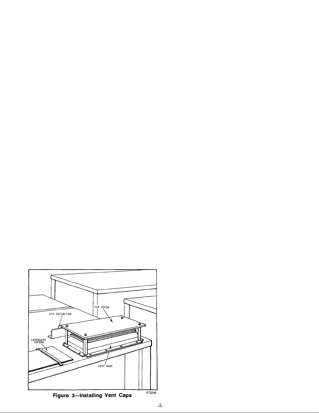
II. INSTALLING VENT CAPS
The vent cap assemblies are packaged and shipped in
the heating section coil compartment. Install the vent
cap assemblies as follows. See Figure 3.
1. Remove the cover on each of the vents on the roof
of the unit.
2. Use the FAJ5606B screws supplied with the assem
blies to fasten the base section of the vent cap assem
bly.
3. Remove the three self-tapping screws in the top
cover, located approximately 7 inches behind each
vent cap. Attach one of the air deflectors in this
location for each vent cap, using the screws removed.
III. DUCT CONNECTIONS
Before attaching the ducting to the unit, remove the
sheet metal panel that is used to protect the outlet
and return openings. The ductwork may be screwed or
bolted to the unit flange with suitable gaskets to in
sure a weathertight seal. Be sure the sheet metal
overlaps the flange on the unit.
CAUTION: Take care not to puncture the evaporator
coil when drilling the duct flange.
All duct work external of the structure must be
properly insulated and water-proofed.
All openings in the structure must be properly flashed
and vibration isolated in accordance with local codes
and good building practices. Supply and return duct
work should be provided with an approved vibration
eliminator. The vibration eliminator must be located
within the structure.
IV. GAS CONNECTIONS
The gas supply pipe for the Model 479 should be a
direct line from the gas meter or propane supply tank.
The gas supply pipe should terminate at the unit with
a tee.
The size of the gas pipe used depends upon the length
of run and allowable pressure loss established by the
utility. Never use pipe smaller than the gas connection
to the unit manifold.
The following are pertinent recommendations:
1. Avoid low spots in long runs of pipe. It is best to
grade all pipe 1/4 inch in every 15 feet to prevent
traps. All horizontal runs should grade up to risers.
2. A drip leg must be provided at any point in the line
of pipe where condensate may collect. Such drip leg or
drip legs shall be installed in locations readily ac
cessible to permit cleaning or emptying. The drip legs
should not be located where they are subject to
freezing. See Figure 4. Check local codes for size and
capacity of drip legs.
3. Three manual shutoff valves should be installed;
one valve between the gas supply pipe and heating
section, and one between each chiller and the gas sup
ply pipe.
4. A ground joint union should be installed between
the individual gas controls manifold and each manual
shutoff valve.
Page 4

DRIP LEG
WITHIN'STRUCTURE
Figure 4—Drip Leg Location
5. The joint compound (pipe dope) used must be
resistant to the action of propane gas.
6. Support all piping with appropriate hangers. Use a
minimum of one hanger every ten feet.
7. After all gas connections are made, check for
leakage using soap and water solution, or leak-check
unit in accordance with local utility regulations.
WARNING: NEVER USE A MATCH OR OPEN
FLAME FOR LEAK TESTING.
Purging Gas Lines
After making all gas connections and checking for
leaks, it is now necessary to purge the supply lines to
eliminate trapped air.
WARNING: NEVER PURGE GAS LINES INTO
THE COMBUSTION CHAMBERS OF THE FUR
NACE OR CHILLERS.
1. With the furnace manual gas valve and pilot
shutoff valve closed, disconnect the pilot supply tube
at the pilot shutoff valve on the furnace.
2. Open the manual shutoff valve; then open the pilot
shutoff valve and allow the supply line to purge until
the odor of gas is detected. Immediately upon detec
ting a gas odor, turn off the gas and reconnect the
pilot supply tube. Allow at least five minutes to elapse
before lighting pilot.
3. Purge the gas line to each chiller in the same man
ner as described for the furnace.
V. ELECTRICAL CONNECTIONS
The Model 479 requires a 3 wire, 230 volt, 60 cycle, 3
phase power supply. Check the unit rating plate to
make sure the power supply meets all the electrical
specifications. Electrical connections must be made in
accordance with the National Electrical Code and the
electrical code of the local area.
The field high voltage connections are made to the
disconnect box located between the two chillers at the
right end of the unit.
The field low voltage wiring consists of running seven
wires from the thermostat subbase to the low voltage
terminal block in the furnace. See Figure 5 for low
voltage field wiring.
Thermostat P/N 34427D55
and
Subhase P/N 34427D59
-4-
Page 5

VI. CHILLED WATER SYSTEM
The cooling section of Model 180-479 is comprised of
two 90,000 BTUH chillers and a 180,000 BTUH
cooling coil which is divided into two separate 90,000
BTUH sections (top and bottom). The bottom section
of the chilled water coil is supplied chilled water by
one chiller (1st stage cooling) while the top section of
the chilled water coil is supplied chilled water by the
other chiller (2nd stage cooling). The chilled water
circuit of each chiller is independent of the other;
therefore, each chiller must be charged with water
before the cooling section can be operated.
The design of Model 240-479 is basically the same as
that of Model 180-479 except the 240-479 utilizes two
120,000 BTUH chillers and a 240,000 BTUH cooling
coil which is divided into two separate 120,000 BTUH
sections. Each chiller of the Model 240-479 must also
be charged with water since the chilled water circuit
of each chiller is independent of the other.
CAUTION: The water seals will be damaged if the
pumps are operated without water in the system.
Freezing conditions will not damage the pumps;
however, do not operate the pumps when the chillers
or chilled water lines are frozen.
Charging the System with Water
Charge the chilled water system with water as
follows:
1. Turn off manual gas valves to both chillers and
turn off electrical power at disconnect switch.
2. Remove access panel from both of the chillers at'
the chiller tank end. Remove chilled water tank lids.
3. Fill both chiller tanks with water having less than
100 ppm chlorides until distributor pans are covered,
or add 12.2 gallons to each chiller of Model 180-479
or 13.6 gallons to each chiller of Model 240-479.
NOTE: If the local tap water has more than 100 ppm
chlorides, charge the chilled water system with
distilled or deionized water. Check the local water
company and/or county agricultural agent for analysis
of tap water being used in your area.
CAUTION: Never use home soft water, water sof
tening additives, water cleaning compounds, coloring
additives, acidizing materials, stop leak additives, or
other commercial water additives in the chilled water
system.
WARNING: To prevent personal injury, disconnect
condenser fan motor lead in the control box of each
chiller at this time.
4. Replace both chiller tank lids, then start water
pumps.
If water of either chiller does not circulate when the
pumps are started, air may be trapped in the system.
Most chillers are equipped with a Gorman-Rupp
water pump (plastic). On these chillers, it is necessary
to disconnect the chilled water line at the chiller tank
to bleed the air. Operate water pumps until water ap
pears at the disconnected water line, then reconnect
water line to chiller tank.
If the chiller with the trapped air is equipped with a
Wayne water pump (metal), it is not necessary to
disconnect the water line to bleed the trapped air.
Bleed the air from the pump through the 1/4-inch slot
ted head valve located on top of the pump discharge.
See Figure 6. Open valve with a screwdriver. Close
valve when a steady stream of water appears.
5. Leak test the chilled water system.
6. Remove operating level drain plug (located on side
of tank) from both chilled water tanks and continue
to operate pumps until water stops flowing from drain
openings.
NOTE: With the pumps running, the water level is
correct for each chiller when water stops flowing from
its drain opening.
7. Replace operating level drain plugs, then turn off
pumps.
8. Refer to “Freezing Weather Protection” on page
6. If freeze protection is required, decide on which
type of antifreeze to use.
The procedure for adding Ucar-17 is given in Step 9.
The procedure for adding methanol antifreeze is given
in Step 10. If antifreeze is not required, disregard
Steps 9 and 10.
9. Adding Ucar-17 Antifreeze - Refer to Table III.
Drain out amount of water from each chiller tank,
equal to amount of antifreeze to be added. Add
required amount of Ucar-17 to each chiller tank.
Recheck operating water level and correct. Do not use
any chilled water additive when using Ucar-17 in the
recommended concentration. Omit Steps 10 and 11.
10. Adding Methanol Antifreeze - Refer to Table III.
Drain out amount of water from each chiller, equal to
amount of antifreeze to be added. Add required
amount of methanol antifreeze. Add the contents of
the chilled water additive package as described in
Step 11.
-5-
Page 6

11. Remove chiller tank lids, and add contents of
chilled water package (one package to each chilled
water tank is sufficient).
12. Replace both chiller tank lids and reconnect con
denser fan motor leads in the chiller control boxes.
13. Turn on water pumps. Pumps should operate a
minimum of 10 minutes to dissolve all chilled water
additive when chilled water additive is used.
14. Replace access panels and tirrn on manual gas
valves to both chillers. Cooling section is now ready to
operate.
Corrosion Protection
The metallic components of the chilled water system
must be protected from corrosion by the addition of
an inhibitor to the chilled water circuit of each chiller.
Two packages of chilled water additive are furnishèd
with the unit. The contents of one package of Chilled
Water Additive P/N 62875D1 must be added to the
chilled water circuit of each chiller when water only
or when water and methanol antifreeze are used in
the chilled water system.
Do not add any chilled water additive to the system
when Ucar-17 is used for freeze protection. Ucar-17
contains sufficient inhibitor when used in the recom
mended concentrations as shown in Table III.
Freezing Weather Protection
Freeze protection is only required when the chilled
water coil is subjected to freezing temperatures or
when the unit is to operate under freezing conditions.
The cooling section is equipped with galvanized
chillers. Ucar-17 is the only permanent (glycol-base)
antifreeze approved for use in the chilled water
system. When Ucar-17 is used for freeze protection,
the minimum concentration must be 33% by volume.
Table III gives the types of antifreeze, percent of an
tifreeze concentration, and amount of antifreeze to
use in each chiller of the 180 and 240-479 at various
outdoor temperatures.
APPROVED ANTIFREEZE TYPES
VII. START-UP AND ADJUSTMENTS
Important: Before starting the heating or cooling sec
tion, make certain all electrical connections have been
made and the gas piping has been connected, purged
and leak tested.
CAUTION; Recheck all factory and field connections,
making sure they are tight.
Pilot Adjustment
Remove necessary access panels from furnace and
chillers.
Light pilots according to instructions on furnace and
chillers.
For Natural Gas. Flame should be of sufficient length
to provide good impingement on the monometal of the
Bryant pilot. The flame should extend upward bet
ween the carryover ports of the two adjacent burners.
For Propane Gas. Flame should surround tip of the
thermocouple element of the pilot and extend down
ward to include 3/8” to 1/2” of the thermocouple. The
flame must not come in contact with any other part of
the thermocuple or its lead wire. The flame lies under
the carryover ports of the burners and merges with the
carryover flames.
The pilot flame can be adjusted if it does not have the
appearance described above. The pilot adjusting
screw for natural and propane units (chillers and fur
nace) is located under a screw cap in the handle of the
manual pilot shut off valve. Adjust as follows;
1. Remove the screw cap to expose the adjusting
screw, then turn pilot flame to full on position.
2. Turn the adjusting screw until the flame has the
desired appearance.
TABLE III
Lowest Outdoor
Temperature (°F)
20
15
10
5
0
-5
'10
-15
-20
-25
-30
^Chilled water Additive (Borax and Chromate) P/N 62875D1 must also be used. Refer
to “Corrosion Protection” on page 6.
**No chilled water additive required. Refer to “Corrosion Protection” on page 6.
Percent of Concentration
^Methanol
20 33 2-1/2 4-1/4
20 33 2-1/2 4-1/4
22
26
29 33
32 36
34 39 4-1/4 4-3/4
36 42
38 45
43 47
44 49
**Ucar-17 Methanol
33 2-3/4
33 3-1/4 4-1/4
-6-
180-479 (Each Chiiier) 240-479 (Each Chiller)
3-3/4 4-1/4
4
4-1/2 5-1/4
4-3/4
5-1/4
5-1/2
Amount Required (Galions)
Ucar-17
4-1/4 3-1/4
4-1/2
5-1/2
5-3/4
6
Methanol Ucar-17
2-3/4 4-1/2
2-3/4 4-1/2
3-3/4
4-1/2 5
4-3/4 5-1/4
5-1/4 6-1/4
4-1/2
4-1/2
4
5
6
6 6-3/4
4-1/2
5-3/4
6-1/2
Page 7

Adjusting Gas Input
Gas input of the furnace and each chiller must be
checked and adjusted if necessary to agree with that
shown on the rating plates. The burners are equipped
with fixed orifices.
CAUTION: The chillers may be run for short periods
with the panels removed. Prolonged operation with
panels removed should be avoided.
Natural gas units are equipped with adjustable gas
pressure regulators. Propane gas units are not equip
ped with a pressure regulator.
One of the following two methods may be used to
check natural gas input on both the furnace and
chillers.
A. Measuring Gas Flow at Meter
All gas appliances must be turned off except the bur
ners on the manifold being checked when measuring
the gas flow at the meter to adjust the gas input.
Proceed as follows:
1. Determine the number of seconds required for the
gas meter test dial to complete one revolution.
2. Divide 3600 by the number of seconds in Step 1.
3. Multiply the result in Step 2 by the number of
cubic feet of gas flow per hour.
4. Multiply the result of Step 3 by the Btu heating
value of the gas (consult local utility for value). This
is the total measured Btu/hr input.
Compare this value with the one shown on the rating
plate.
Example: Suppose the size of the test dial is 5 cu. ft.;
it takes 40 seconds for the dial to complete one
revolution; heating value of the gas is 1050 Btu/cu. ft.
Proceed as follows:
40 seconds to complete one revolution
3600 divided 40 equals 90
90 X 5 - 450 cu. ft. per hour of gas flow
450 X 1050 - 472,5000 Btuh input
Only minor changes should have to be made at the
pressure regulator to bring it within the rated input of
the unit. If the manifold pressure must be changed
more than 0.3” w.c. to obtain the rated input, the
orifices should be changed accordingly.
B. Using Water Manometer
Proceed as follows when using a water manometer to
measure the manifold pressure when adjusting the gas
input:
1. Connect a water manometer to the 1/8” pressure
tap on the manifold or gas valve.
2. With the burners fired, set the correct manifold
pressure as shown in Table IV. Check with the gas
utility for the Btu valve and specific gravity of gas in
the area.
TABLE IV—MANIFOLD PRESSURE
(Inches W.C.)
Specific Gravity
0.59 0.61 0.63 0.65 0.67
900 3.9” 4.0”
950 3.5” 3.6” 3.7”
1000 3.1”
1025 3.0”
1050 2.8” 2.9” 3.0” 3.1”
1100 2.6”
Adjusting Pressure Regulator
3.2” 3.3”
3.1”
2.7” 2.8”
4.1”
3.2” 3.3” 3.4”
4.2” 4.3”
3.8” 3.9”
3.4” 3.5”
3.2”
2.9” 3.0”
If the measured and rated input are not ap
proximately the same, the gas pressure regulator may
be adjusted as follows:.
To increase input. Remove regulator sealing cap
and turn gas pressure regulator adjusting screw
clockwise.
To decrease input. Remove regulator sealing cap and
turn gas pressure adjusting screw counterclockwise.
Checking Propane Gas Input
The burner orifices are sized for rated input with a
manifold pressure of 11.0” w.c. for propane gas. Con
nect a manometer of the 1/8” pressure tap on the
chiller manifold gas valve. With the burners fired, ad
just regulator at the supply tank to provide a pressure
of 11.0” w.c. Check manifold pressure of each chiller.
Cheek the furnace manifold pressure to see that it is
also 11.0 inches w.c.
Burner Adjustment
To adjust the primary air to each burner, partially
close the air shutter until there is a slight yellow tip at
the top of each ñame, then open the air shutter until
the yellow tip just disappears. This should be done af
ter the burners have been operating at full input for 5
minutes.
VIII. FURNACE OPERATION
In order to check the furnace for proper performance,
the following sequence of control operation is given.
CAUTION: The pilot valve and main burner manual
valve must be closed for at least five minutes before
starting the furnace.
1. Set the thermostat system switch to “heat”, set the
fan switch to “auto” and set the thermostat below
room temperature.
2. Turn on electricah power to the unit.
3. Open pilot gas valve. Gas will flow to the pressure
switch and to the pilot. The electrical contacts in the
pressure switch close, energizing the reignition coil
which ignites the pilot gas. (Natural gas only; pilots
on propane unit must be lighted manually per instruc
tion on rating plate.)
The pilot flame causes the monometal contacts in the
Bryant 733 pilot to “Break” the re-ignition coil circuit
-7-
Page 8

and “make” the circuit to, but not through, the first
stage gas valve. On propane units, with themocouple
energized, the pilot relay switch action makes the cir
cuit to gas valve.
4. Set the thermostat above room temperature. This
completes the circuit and energizes the gas valve.
5. Gas flows through the gas valve to the burners via
bypass where it ignites. If the conditioned space tem
perature continues to drop, the second stage of the
thermostat closes and opens the second gas valve
bringing the unit to full input.
With the furnace operating, make the following
checks:
The automatic pilot should turn the main gas off if
the pilot flame goes out.
Check this while the furnace is operating by shutting
off the pilot gas. The main burners should shutdown.
Allow the furnace to cool and the blowers to stop,
then check the upper limit switch.
Limit Control
The furnace is equipped with a lower and upper limit
control. When the lower limit opens, the first stage gas
valve is de-energized, shutting off the gas. The upper
limit control has a dual function; its primary action
is to shut off the first stage gas valve if the unit
overheats; as the gas valve is shut off, the fan delay
relay is energized, starting the blower. The upper
limit is a single pole double throw switch.
The recommended method for checking the limit con
trols is to gradually block off the return air after the
furnace has been operating for a period of at least five
minutes. As soon as the limit has proven safe, the
return air openings should be unblocked to allow nor
mal air circulation through the unit. Whether or not
the limit is functioning properly, and will “fail-safe”
in case of motor failure or overheating of the unit can
be determined using this method.
Fan Relay
The unit is equipped with a fan delay relay switch
located in the control box. When the observer faces
the control, the adjustment lever is moved upward to
lengthen the off cycle. When the off cycle is
lengthened, the on cycle is shortened automatically.
Reverse the process to shorten the off cycle.
Airflow and Temperature Rise
The temperature rise is the difference between the
temperature of the air in the return duct and that in
the discharge duct near the furnace. This temperature
rise, measured after equilibrium has been attained
(approximately five minutes), should be within the
range of 45°F to 75°F for Model 180-479 and 20°F to
50°F for Model 240-479.
An adjustable sheave on the blower motor pulley is
used to adjust the blower speed as follows:
CAUTION: Turn off electric power to unit before
removing or replacing blower belt. Proceed as follows:
r
1. Loosen the motor from the base and slide the
motor toward the blower housing. Remove the belt
from the blower.
2. Loosen the set screw in the movable flange of the
sheave. Screw the movable flange toward the fixed
flange to increase the blower speed, away from the
fixed flange to reduce the blower speed. Tighten the
set screw on one of the two flat surfaces on the pulley
hub.
Important: Increasing the blower speed will impose a
greater load on the blower motor. Do not exceed the
rated current draw of the motor.
3. Replace the belt and adjust for proper tension. The
belt should have approximately 1” sag under normal
finger pressure.
4. Check motor pulley and blower pulley for proper
alignment.
IX. COOLING OPERATION
Perform the following steps to check the cooling sec
tion for proper operation.
WARNING: The main manual gas valve for
both chillers must be closed for at least 5 minutes
before operating the cooling sections.
1. Be sure the manual gas valves for both chillers are
in the OFF position. Light pilots as described on In
struction Plate.
2. With the thermostat subbase switch levers on
COOL and AUTO, turn on both manual gas valves.
Set thermostat at its lowest setting. Make certain both
chillers are operating. To check for correct operation
of the electrical circuit; observe operation of gas valve
and solution pump of each chiller, all condenser fan
motors and the blower. Increase the setting of the
thermostat gradually until one chiller shuts off. Set
thermostat above room temperature and observe that
the other chiller shuts off.
3. Set thermostat subbase fan switch to ON and check
blower operation. The blower should run continually
with the thermostat set above or below room tem
perature.
4. To place the system in operation, replace all panels
and set thermostat at the desired temperature.
SEQUENCE OF OPERATION
(Cooling Section)
Both the 180-479 and 240-479 are equipped with two
stage cooling. Chiller No. 1 operates on the initial call
for cooling (single stage cooling). When additional
cooling is required, Chiller No. 2 is also activated
(two-stage cooling).
Refer in Figures 7 and 8. When the thermostat system
switch is in the COOL position and the fan switch is in
the AUTO position, the first stage cooling bulb in the
thermostat will close the circuit between terminals Y1
and R, and between terminals Yl and G when the
thermostat calls for cooling.
Closing the circuit between terminals Yl and G
energizes the blower relay (2A1) and closes its nor
-8-
Page 9

mally open contacts. This causes current to flow
through the contactor (2M) winding and energizes the
contactor. The energized contactor starts the blower
motor (3E).
Closing the circuit between terminals Y1 and R com
pletes the control circuit for Chiller No. 1 and turns
this chiller on for single stage cooling. Chiller No. 2 is
inactive and will not operate until the temperature in
the conditioned space rises and calls for additional
cooling.
If the cooling load of the conditioned space is too
large for Chiller No. 1 to provide sufficient cooling,
the thermostat’s second stage cooling bulb will close
the circuit between Y2 and R.
Closing the circuit between Y2 and R, places the con
trol relay (2A2) across the secondary of Chiller No. 1
transformer (lAl). The energized control relay (2A2)
completes the control circuit of Chiller No. 2 and
turns this chiller on (two stage operation).
When the thermostat is satisfied, the thermostat’s
second bulb will break the circuit between terminals
R and Y2. This action de-energizes the control relay
(2A2) which opens the control circuit of Chiller No. 2
and turns off Chiller No. 2. Chiller No. 2 will remain
idle until additional cooling is required.
HIGH TEMPERATURE CUTOFF
(Model 180-479)
Refer to Figure 7. Each chiller of Model 180-479 is
equipped with a high temperature limit switch (7H1
on Chiller No. 1 and 7H3 on Chiller No. 2) located on
the front of the generator, plus a circuit breaker (2Jl
on Chiller No. 1 and 2J2 on Chiller No. 2). The circuit
breaker for each chiller is located in the chiller con
trol box.
If the generator of either chiller becomes overheated,
its associated limit switch (7H1 or 7H3) will open,
providing a current path through heater element of
the circuit breaker (2Jl or 2J2) of the respective
chiller. The current flow through the heater element
of the circuit breaker will cause its normally closed
contacts to open and break the 24-volt circuit to the
magnetic gas valve (5B1 or 5B2). The de-energized
gas valve will turn off the gas supply to the burners of
the overheated generator. The remaining normally
operating chiller will continue to operate.
The circuit breaker must be reset manually by
pushing the red reset button that protrudes through
the rear of the chiller control box.
A secondary high temperature limit switch (7H2 on
Chiller No. 1 and 7H4 on Chiller No. 2) is connected
in series with the gas valve (5B1 on Chiller No. 1 and
5B2 on Chiller No. 2) to insure closing of the gas valve
in the event of a high temperature failure and the
limit switch (7H1 on Chiller No. 1 and 7H3 on Chiller
No. 2) does not open.
The secondary limit switch is located on the generator
header and must be reset manually.
HIGH TEMPERATURE CUTOFF
(Model 240-479)
Refer to Figure 8. Each chiller of the 240-479 is
equipped with two high temperature limit switches
(7H1 & 7H2 on Chiller No. 1, and 7H5 & 7H6 on
Chiller No. 2). A high temperature limit switch is
located on the front of each generator of each chiller.
If either generator of Chiller No. 1 becomes
overheated, the associated high temperature limit
switch (7H1 or 7H2) will open, causing the circuit
breaker (2J1) to go into lockout position. The open
contacts of the circuit breaker de-energizes the gas
valve and shuts off the gas supply to the burners of
both Chiller No. 1 generators.
The circuit breaker (2Jl).for Chiller No. 1 is located
in the Chiller No. 1 control box and must be reset
manually.
Two secondary high temperature limit switches (7H3
and 7H4-one on each generator header of Chiller No.
1) are connected in series with the Chiller No. 1 gas
valve (5B1). If a generator overheats and its
associated high temperature limit switch (7Hl or
7H2) does not open, the secondary high temperature
limit switch (7H3 or 7H4) on the header of this
generator will open and break the circuit to the gas
valve, de-energizing the gas valve and shutting off
the gas supply to the burners .of both Chiller No. 1
generators.
The high temperature cutoff circuit of Chiller No. 2
functions the same as the high temperature cutoff cir
cuit of Chiller No. 1. The high temperature cutoff cir
cuit of Chiller No. 2 is comprised of high temperature
limit switches 7H5 and 7H6, circuit breaker 2J2,
secondary high temperature limit switches 7H7 and
7H8.
If a high temperature failure should occur and disable
Chiller No. 1, Chiller No. 2 will continue to operate
and provide single stage cooling; likewise. Chiller No.
1 will provide single stage cooling if a high tem
perature failure should disable Chiller No. 2.
AMBISTAT PART LOAD CONTROL
(Models 180-479 and 240-479)
Refer to Figures 7 and 8. Each chiller is equipped
with an ambistat part load control (7L1 on Chiller
No. 1 and 7L2 on Chiller No. 2). The circuit consists
of a temperature sensitive switch (located in the
chiller control box) and a capillary tube. One end of
the capillary tube is connected to the switch and the
other end is inserted in the chilled water supply line.
The switch contacts open when the chilled water tem
perature drops below 40°F. and breaks the circuit to
the gas valve, shutting off the gas supply to the
burners.
The chiller power relay remains energized and the
condenser fan motors, solution pump and water pump
will continue to run.
Page 10

The ambistat switch contacts will close again when
the chilled water supply temperature rises to 42°F.
The energized gas valve turns the gas on again.
X. MAINTENANCE
Cleaning the Heating Unit.
1. Be sure that the main line disconnect switch is in
the OFF position.
TAG SWITCH WITH A SUITABLE WARNING
LABEL.
2. Remove the front access panel.
3. Turn off the manual gas valve and the pilot valve.
4. Disconnect the pilot and escapement tubing.
5. Remove the burners.
6. Remove the flue baffle retainer and the flue baf
fles.
7. Clean the flue passages with a suitable brush.
8. Reassemble the furnace by reversing the above
procedure, making sure all seals are reinstalled
properly.
9. Check belt conditions and proper tension of belt
(approximately 1/2 inch deflection).
10. Filters in the 180-479 are of the disposable type
and should be inspected periodically and replaced
when dirty with filters of the same type and size.
Filters in the 240-479 are permanent type filters and
should be cleaned periodically. Make sure the arrows
on the edge of the filter point in the direction of the
airflow.
Lubrication
Some blower motors are equipped with permanent
lubricated bearings and require no further
lubrication.
Blower motors that require lubrication are equipped
with oil cups. Oil motor bearings with SAE 10-20 non
detergent oil each heating and cooling season.
NOTE: BLOWER BEARINGS ARE OF THE PER
MANENT LUBRICATED TYPE AND DO NOT
REQUIRE ANY FURTHER OILING.
Cleaning the Condenser Coil
The condenser coil fin surfaces should be inspected
from time to time and cleaned as necessary. Cleaning
may be accomplished by washing the fins with low
pressure water from a garden hose. Detergent may be
used, prior to rinsing, when oil or grease has coated
the fin surfaces. Care must be taken to be sure that
the soft aluminum fins are not bent.
WARNING: Disconnect the electric power before
cleaning the cooling coil.
Summer Chiller Operation
It may be necessary to drain, flush and refill the
chilled water system of each chiller with tap water if
antifreeze was used for winter protection. A high an
tifreeze concentration will result in a reduction of the
cooling capacity of the unit.
Be sure to add one package of Chilled Water Additive
P/N 62875D1 to the chiller tank of each chiller of
Model 180-479 or the Model 240-479 when water only
is used in the chilled water system for summer
operation.
-10-
Page 11

9E 1IB2
LEGEND
1A1 & 1 A2-Transformer (Cooling)
1 B-Transformer (Heating)
2A1-Blower Relay, SPST, (Cooling)
2A2-Control Relay, SPST
2D1 & 2D2-Power Relay, DPST, (Cooling)
2G-Heating Relay
2J1 & 2J2-Relay Circuit Breaker Lockout
2M-Blower Contactor, TPST
3A1 & 3A3-Solution Pump Motor
3A2 & 3A4-Water Pump Motor
3C1 Thru 3C4-Fan Motor, PSC
3E-Blower Motor
5B1 & 5B2-Gas Valve (Cooling)
5B3-Gas Valve (1st Stage) (Heating)
5B4-Gas Valve (2nd Stage) (Heating)
6B1 Thru 6B4-Reignition Pilot
Figure 7—Model 180-479 Wiring Diagram
7A1 & 7A2-Pressure Switch, SPST
7H1, 3, & 5-Limit Switch (High Temp Cent.)
7H2, & 4-Limit Switch (Sec. High Temp.
Manual Reset), SPST
7K-Limit Switch, Upper, SPOT
7L1 & 7L2-Ambistat (Part Load Control),
SPST
7P1 Thru 7P3-Pressure Switch,
SPST
9E-Disconnect Switch
11A1 Thru 11A3-Resistor
11B1 & 11B2-30 Amp. Fuse
11B3-50 Amp Fuse
4E1 Thru 4E4-Capacitor
Pilot Gas,
Page 12

LEGEND
A70216
1A1 & 1A2-Transformer (Cooling)
1B-Transformer (Heating)
2A1-Blower Relay, SPST, (Cooling)
2A2-Control Relay, SPST
2D1 & 2D2-Power Relay, DPST, (Cooling)
2G-Heating Relay
2J1 & 2J2-Relay Circuit Breaker Lockout
2M-Starter, Blower TPST
3A1 & 3A3-Solution Pump Motor
3A2 & 3A4-Water Pump Motor
3C1 Thru 3C6-Fan Motor, PSC
3E-Blower Motor
5B1 & 5B2-Gas Valve (Cooling)
5B3-Gas Valve (1st Stage) (Heating)
5B4-Gas Valve (2nd Stage) (Heating)
6B1 Thru 6B6-Reignition Pilot
7A1 & 7A2-Pressure Switch, SPST
Figure 8—Model 240-479 Wiring Diagram
7H1, 2, 5, 6, & 9-Limit Switch SPST (Temp
Cont.)
7H3, 4, 7 & 8-Limit Switch (Sec. Temp Cont.
Manuai Reset), SPST
7K-Limit Switch, Upper, SPOT
7L1 & 7L2-Ambistat (Part Load Control),
SPST
7P1 Thru 7P3-Pressure Switch, Pilot Gas,
SPST
8C1 Thru 8C3-Starter Overload (Manual
Reset)
9E-Disconnect Switch
11A1 Thru 11A3-Resistor
11B1 & 11B2-45 Amp. Fuse
11B3-70 Amp. Fuse
4E1 Thru 4E6-Capacitor
Page 13

479
Sizes 180 & 240
Installation Instructions
Series E
I
ATTACH TO INSTALLATION INSTRUCTIONS 39479D8
Use attached 39479D8 Installation Instructions (with changes indicated below) to in
stall sizes 180 and 240 of Model 479, Series E, units.
Models 180- and 240-479 Series E units differ from Series D units as described below.
1. GAS INPUT to the cooling section of Model 180-479 was Increased from 450,000 Btuh
to 492,000 Etuh C.246,000 Btuh input each chiller). The generator burner orifices
were changed from #39 drill size to #36 drill size on the natural gas unit. The
burner orifices on the propane unit were changed from #53 drill size to #52 drill
size.
39479D12
4/1/72
2. GAS INPUT to the cooling section of Model 240-479 was increased from 600,000 Btuh
to 640,000 Btuh C320,000 Btuh input each chiller). The generator burner orifices
were changed from #41 drill size to #39 drill size'on the natural gas unit. The
burner orifices on the propane unit were changed from #54 drill size to #53 drill
size.
3.
AUTOMATIC PILOT REIGNITION is used on both natural and propane units in both the
heating and cooling sections on both Models 180- and 240-479. The wiring diagrams
on pages 11 and 12 apply to both natural and propane gas units.
4.
FUSE SIZE was changed on Model 180-479.
30 amp fuses.
NOTE: Hydraulic Pump Heater Kit P/N 65134D01 (2 required) must be field installed on
each chiller if the cooling section is to be operated at outdoor temperatures below
40°F. Adding the heater kits permits operation of the cooling section at outdoor temp
eratures down to -30°F. Antifreeze must also be added for protection at the lowest
outdoor temperature.
The 180-479 now uses one 60 amp and two
'L E
DON
\ /1““^!
 Loading...