

p
ALL WEATHER
HEATING & COOLING UNIT
0 478
§ Size 90
PDS 478.90.1 10/11/68
__ ..i
SPECIFICATIONS
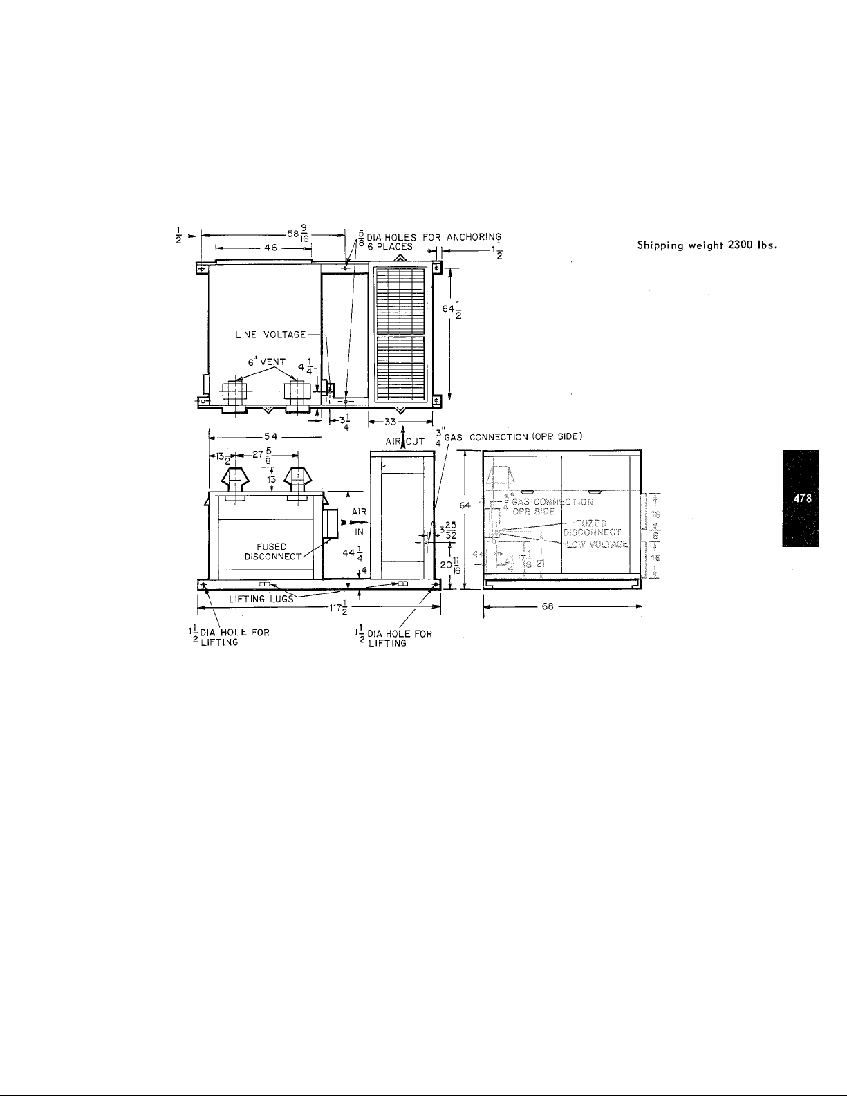
This equipment is a gas heating and gas cooling all-weather unit designed for roof-top or ground
level installations.
It makes use of an air-cooled Bryant 90-452 gas-fired water chiller combined with a Bryant
300-378 heating unit conveniently mounted on an integral base for easy installation. 'Tie unit is
rated at 90,000 Btuh cooling and 300,000 Btuh heating input. 'The heating can be modulated to
100,000 Btuh input for natural gas by using a modulating gas control kit, Part No. 60119CO2. The
gas-fired chiller is standard with automatic fuel modulation to save gas under low load conditions.
Installation does not interfere with other building trades. No inside floor space and no special
vents are required. Just set the unit on slab or adequate roof support and connect duct, gas supply
and electric supply. 'The Bryant absorption cycle is already charged and ready for operation.
The weatherproof cabinet is made from heavy gauge zinc-coated steel; the chiller finish is baked-
on enamel, and the conditioned-air section is lined with fiberglass to insulate and assure quiet
operation.
Removable panels allow easy access to all components and controls for both heating and cooling.
Automatic pilot reignition eliminates the need for seirvice calls due to pilot outage; a stainless
chromized steel heat exchanger promises long life .
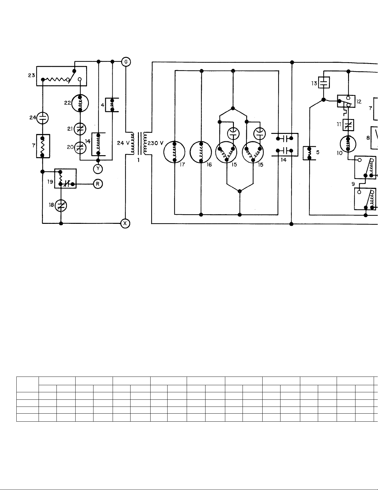
1 . Transformer
2. Blower motor
3 . Combustion air blower motor
4 . Fan relay cooling
5 . Delay relay heating
6 . Combustion air fan relay
10. Gas valve
11. Limit switch adj.
12 . Limit switch non-adj.
13 . Combustion air pressure switch 22
14 . Power relay (cooling) 23
15 . Condenser fan motor 24
7 . Resistor 16. Chilled water pump
8. Pilot gas pressure switch 17. Solution pump
9 . Pilot auto reignition 18. High temp cut-out (cooling)
AIR DELIVERY AT INDICATED EXTERNAL S.P. WITH WET COIL
CFM
2500
3000
3500
4000 835
Shaded portions of the table are beyond the standard drive range or motor horsepower. Standard drive range 540-870 RPM.
0
RPM BMP RPM
500
650
740
.464
.650
.900
1.20
0.1 " 0.2"
BHP RPM BHP RPM BHP
620
700
790 .966 825
890
.500
695
750 .798 800
.734
1.30 920 1.38 960
.560
1.05
0.3"
RPM BHP
725 .665 775
840 .932 870
.866
870
1.10
1.45
900 1.20 940
990
0.4" 0.5" 0.6" 0.7"
RPM BHP
.732
1.55 1025
805 .798
1.00
1.30 980
1.70 1060 1.80
RPM
BHP
860
.865 900 .932
910 1.10
1.33 1005 1.43
RPM BHP
1.20 1000
955
- -
19
20
; 21
RPM
940
1050
0.8"
-
High t
Part 1(
High p
Gas Vc
Auto p
Pilot g
BHP
1.00
1.25
1.50
-

COOLING CAPACITY
Capacity Total
Air Flow
External S.P.
Entering Water Temp
Entering Air (C.W. Coil) °F
Water Flow
Outdoor Ambient
BTUH
CFM
In. wg.
°F
GPM
°F 95
HEATING CAPACITY
Input BTUH
Output BTUH
Approved Temp Rise °F
CFM at 75°F Rise
* May be modulated to 100,000 Input.
*300,000 - 200,000
225,000 - 150,000
20 - 75
2780 at 225,000 Output
1850 at 150,000 Output
ELECTRICAL CONNECTIONS
Power Supply
Branch Circuit Wire Size Minimum
Branch Circuit Fuses (2) 35 A Cart. Fusetron
208/230-60-1
8 AWG
90,000
3,000
.5
45
80/67
18.5
19. High temp lock-out manual reset (cooling)
20 . Part load control
21 . High pressure switch (cooling)
22 . Gas valve (cooling)
23 . Auto pilot reignition
24. Pilot gas pressure switch
\ WET COIL
3
2
0.8"
RPM BHP RPM BHP RPM BHP RPM
940 1.00
1000
1.25
1050
1.50
- - -
0.9"
1.10 1000
975
1040
1.35
1100 1.50
- -
1 0" 1
1.20
1.40
1075
1130 1.80
- - -
1040
1105
1 "
BHP
1.25 1075
1.50 1140
- - - -
1.2"
RPM BHP
1.30
1.60
- -
GAS CONTROL INFORMATION
Burners - Heating Unit Steel Slotted Port
Number
Orifice - Natural »41 (300,000)
Orifice - Propane
Orifice - Natural »47 (200,000)
Orifice - Propane
Burners - Chiller Aluminum Dipped Steel
Number 8
Orifice - Natural
Orifice - Propane
Valve - Heating Unit Bryant 3/4" A639B
Valve - Chiller
Limit Heating (2)
Limit Chiller (2)
Ignition - Heating Unit
Ignition - Chiller
Fan Control - Heating Delay Relay
Fan Control - Cooling
Pilot - Heating
Pilot - Chiller
Gas Connection - Heating 3/4 NPT
Gas Connection - Chiller
Heat Exchanger - Heating
12
»55 (300,000)
»57 (200,000)
»39
»53
Bryant 3/4" A639B
Automatic Reset
(1) Auto Reset (1) Manual
Automatic
Automatic
S.P.S.T. Relay
Bryant 2 - H
Bryant 733
3/4 NPT
Stainless Chromized Steel

COMPONENT INFORMATION
Chilled Water Coil
Area
Height X Width
Tube OD
Rows
Fins
Pattern
Circuits
Blower Wheels No.
Diameter x Width Inches 12-5/8 X 12-5/8
Blower Motor (Std)
Speed
Frame 56
Rotation ccw
Voltage (Std) 208-230-60-1
Full Load Amps
Locked Rotor Amps 35
Blower Motor Pulley
Blower Pulley Inches
Belt Length x Width Inches
Filters
Sq. Ft. 7.92
Inches
Inches
HP & SF
RPM 3450
Inches
30 X 38
1/2
3
12/In. Flat Fan Diameter
1.25 X 1.08 Stag.
9
2
1 X 1.25 Frame
6.7
PD 2.9 - 1.9
PD 12 Full Load Amps
51 X 1/2
(4) 25 X 20 X 1
DETAILED COOLING CAPACITIES
AIR ENTERING
C.W. COIL
85
CHILLER
Capacity
CFM
EWB
Btuh X 1000
Total Sensible Total Sensible
93.5 48.1
89.5 57.8
65.9 79.3 65.1
93.6 50.2
2,500
71
67
63 81.5
71
3,000 67 92.5 62.5
63
71
3,500
67
63 87.5
71
4,000 67
63
85.5 72.3
93.7
52.5 92.2
93.0 66.2 91.0
77.9
93.8
55.3
93.4 69.6
89.5 83.4
Chilled Fan Motor
Voltage (Std)
Speed
Full Load Amps
Locked Rotor Amps
Chilled Water Pump
HP & Service Factor
Voltage
Speed
Full Load Amps
Locked Rotor Amps
Solution Pump Motor
HP & Service Factor
Voltage
Speed RPM
Frame
Locked Rotor Amps
Pump Pulley Diameter
Motor Pulley Diameter
Belt Length x Width
RPM
Inches
RPM
Inches
Inches
ENTERING AIR TEMPERATURE ° F
95
Capacity
Btuh X 1000
Total
92.0
88.0
92.1
90.0
83.7 71.6
47.5 87.0
57.2 83.5
49.9
61.6 85.7 59.9
79.5 70.0
52.2
65.4 86.0
85.7 77.1
92.3
91.5 69.1
54.4 87.3
86.5 67.4
87.5 82.5
(2) 1/2 HP
208/230-60-1
1075
3.6
10.5
(2) 22.12
1/3 - 1.75
208/230-60-1
3450
48
3.6
23.0
3/4 - 1.25
208/230-60-1
1725
55
5.4
29.5
7.84
2.3
36.42 X 3/16
105
Capacity
Btuh X 1000
Sensible
45.6
55.6
75.0
63.2
87.1 48.3
87.2
50.7
63.9
81.3
75.6
53.1
82.5
80.8
Notes:
1. Sensible heat capacities shown are based on 80 F entering air at the evaporator.
2. Direct interpolation is permissible. Do not extrapolate.
3. To interpolate:
(a) below 80 F DB, subtract 800 Btuh per 1000 cfm
for each degree below 80 F from the listed sensible capacity.
(b) above 80 F DB, add 800 Btuh per 1000 cfm
for each degree above 80 F from the listed sensible capacity.
4. Formula:
LDB = EDB -
Lh - Eh -
Sensible Heat Capacity (Btuh)
1.08 X cfm
Total Capacity (Btuh)
4.5 X cfm
where h = Enthalpy (Btu/lb)
 Loading...