

Page 1
Installation Instructions
452W
SIZE 90
Series E
GAS-FIRED AIR CONDITIONER
Important—Read before Installing
1. Check all local or other applicable codes for in
formation concerning proximity to property lines,
height above roof, obstructions, etc.
2. Be sure the power supply available (voltage,
frequency, and phase) corresponds to that
specified on the unit rating plate.
3. Check the electrical service provided by the
utility for the building to be sure that the service
capacity is sufficient to handle the load imposed
by this unit.
4. Refer to the regulations of the serving gas sup
plier and the local building, heating, plumbing,
or other codes in effect in the area in which in
stallation is to be made.
5. Refer to the dimensional drawing on page 2 for
location of electrical, gas, and chilled-water con
nections prior to setting the unit in place.
C^els: 39452D70
FIL
OP
DO NOl
REMOV
bri|ant
39452D80
2/15/73
I
GENERAL
Model 90-452W is a gas-fired air-cooled absorption
unit designed to satisfy the cooling needs of com
mercial and industrial buildings. This absorption unit
supplies chilled water for cooling with Bryant’s indoor
and outdoor coil assemblies.
Multiple Chillers and Cooling Coils
When it is planned to connect two or more chillers or
coils, additional piping and electrical information is
required and should be obtained from your Bryant
Distributor. When making multiple chiller in
stallations, it is recommended that only Models 452
and 452W be interconnected. Interconnection of sizes
60, 90, and 120 is permissible, but the use of other
model chillers with Models 452 and 452W in a
multiple system should be avoided.
Operation at Atmospheric Pressure
The chilled-water tank on this unit is vented to the
atmosphere; consequently, the chilled-water circuit
operates at atmospheric pressure. Therefore, con
ventional piping practices for a closed, pressurized
system do not apply for this unit.
NOTE: When the water chiller is piped to a boiler as
described below, the indoor coil operates at or near
atmospheric pressure when used for cooling; the in
door coil may be pressurized when it is used with the
boiler for heating.
Figure 1 - Model 90-452W Gas Air Conditioner
When this chiller is piped with a boiler to form a com
bination heating and cooling system, provisions must
be made for a positive shutoff between the chiller tank
and the boiler.
When the boiler is in operation, the^ chiller tank must
be bypassed. A sediment strainer must be installed at
the chiller tank inlet when a common pipe connects
the chiller tank and boiler.
When the chiller is in operation the boiler, of course,
should be bypassed.
Installation
Installation of the Model 90-452W, Series E Gas
Chiller unit consists of the following steps:
I. Locating and Mounting the Unit
II. Connecting Chilled-Water Lines
III. Making Electrical Connections
IV. Making Gas Connections
V. Chilled-Water System
VI. Checking the Unit Operation
VII. Adjusting Gas Input
VIII. Balancing the System
Each of the above steps is discussed in detail in this
instruction. Read the entire instruction before starting
the installation.
Page 2
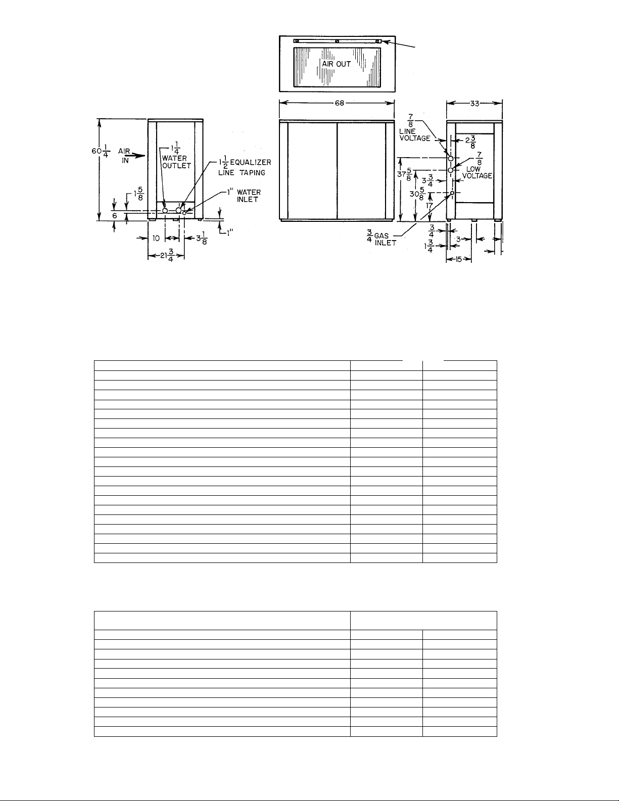
AIR OUT
Figure 2 - Dimensionai Drawing
RATiNGS AND PERFORMANCE
MODEL
Unit Rating Plate (Voltage-Hertz-Phase)
Cooling Capacity
Gas Input
Condenser Air Delivery
Chilled-Water Flow Rate (Nominal)
Max Head at Nominal Water Flow Ft Water
Electrical Input KW 2.5
Fan Motor (2) HP & SF
Voltage Hertz-Phase
Capacitor (370 Volts)
Hydraulic Pump Motor
Voltage-Hertz-Phase
Alternate Hydraulic Pump Motor HP & SF
Voltage-Hertz-Phase
Chilled-Water Pump HP & SF
Voltage-Hertz-Phase
Refrigerant
Amount
Total Solution
Bryant Sound Rating
Approximate Shipping Weight
Btuh
Btuh
CFM
GPM 18.75
mfd 10 7.5
HP & SF
Type
Lbs 18
Lbs
SRN
Lbs
200-60-1 230-60-1
90,000 90,000
246,000 246,000
10,000 10,000
37 37
1/2 & 1.0 1/2 & 1.0
200/230-60-1 200/230-60-1
1 & 1.25
200-60-1
1 & 1.25
200-60-1
1/3 & 1.35
200-230-60-1 200-230-60-1
R717
55
22
1317
COIL CLEANING
ACCESS PANEL
90-452W
Series E
1-1/2 & 1.25
208/230-60-1
1/3 & 1.35
4
-5
18.75
2.5
1 & 1.25
230-60-1
R717
18
55
22
1317
CONNECTIONS
MODEL
Unit Rating Plate (Voltage-Hertz-Phase)
**Maximum Line Length
Control Circuit Volts 24 24
External Power Available VA
Gas Supply Connection Size
Chilled-Water Supply (NPT)
Chilled-Water Return (NPT) Inches 1 FPT
Equalizer Line (NPT)
*If other than 75 °C copper conductor is used, determine size from unit ampacity and the National Electric Code.
Voltage drop of wire selected must be less than 2% of unit rated voltage.
**Length shown is for one way along the wire path from unit to service panel.
Unit Ampacity for Electrical Conductor Sizing Amps
*Min Branch Circuit Wire Size
Recommended Fuse Size
AWG No.
Amps 35 35
Ft
Inches 3/4 NPT 3/4 NPT
Inches
Inches 1-1/2FPT 1-1/2FPT
200-60-1
1-1/4FPT
90-452W
Series E
230-60-1
19.25 26.2
12 10
71 115
5 5
1-1/4FPT
1 FPT
— 2.
Page 3

REFRIGERANT RESTRICTORS HIGH-PRESSURE
(CHILLER INLET) LIMIT SWITCH RECTIFIER
SECONDARY
HI-TEMP
LIMIT
SWITCH
AMBISTAT
PILOT
PRESSURE
SWITCH
REGULATOR
MANUAL
SHUT-OFF
VALVE
GAS VALVE
MAINTENANCE
LABEL
GENERATOR PILOT HI-TEMP LIMIT SWITCH
Figure 3 - Unit Front View With Access Panels Removed
VALVE C
S' .
IL
■
' V"
CHILLEDWATER
TANK
VALVE E
---------
PUMP
DISCHARGE ------TANK
PUMP
HEATER
A72597
VALVE A
■ VALVE D
■
Figure 4 - Unit Left-Side View With
Access Panel Removed
— 3
HYDRAULIC SOLUTION
PUMP PUMPS
MOTOR
Figure 5 - Unit Right-Side View With
Access Panel Removed
Page 4

I. LOCATING AND MOUNTING UNIT
The absorption unit is approved for outdoor in
stallation only and may be located at ground level or
on the roof. Consult local or other applicable codes for
information concerning proximity to property lines,
height above roof, obstructions, etc.
3. Leave sufficient clearance (6 inches minimum)
between unit base and roof for proper air cir
culation when installing unit on a roof. Use
precast concrete lintels or concrete blocks as
described in paragraph 2, or use steel beams.
Check local codes. Refer to NBFU code for In
stallation of Heat Producing Appliances.
A. Mounting Base
1. USE NONCOMBUSTIBLE MATERIALS.
2. Suggested types of mounting base for ground in
stallation ;
a. Precast concrete lintels. Use three lintels the
depth of unit, one each under right and left
end of unit, and one at center of unit.
b. Concrete blocks. Use one block at each corner
of unit plus blocks under the two long sides
midway between the corner blocks.
c. Concrete slab. Minimum thickness 4 inches.
II. CONNECTING CHILLED-WATER LINES
B. Clearances
1. Absorption unit should have a minimum clear
ance of 2 feet on all sides from any adjacent
obstruction.
2. Avoid locating the unit where hot condenser air
can impinge on nearby obstructions and mix with
the inlet air supply. The condenser air discharges
upward. The unit should be located outside of
the plumb line from any overhang when the
distance from the overhang to the top of the unit
is less than 7 feet.
Refer to “Multiple Chillers and Cooling Coils,” page 1; “Operation at Atmospheric Pressure,” page 1; and
“Chilled-Water System”, page 7, before making any chilled-water connections.
1
TABLE I
^Allowable Distance Between Coil & Chiller
Nominal
Pipe Size
(Inches)
1 30
1-1/4
1-1/2
NOTE; Values shown in Table I are for one direction only. The total length of pipe from chiller to coil and return would be double the values given.
The above table applies to single unit installations only.
A. Materials
NOTE: Black iron pipe must not be used for chilled-
water piping.
1. Piping
a. Polyethylene Plastic Pipe - use medium den
sity flexible pipe whose wall thickness
approximates Schedule 40 pipe (Commercial
Standard CS 255-63). Pipe must be virgin
plastic. Do not use pipe manufactured from
reclaimed plastic.
b. Copper—satisfactory substitute.
Polyethylene
Pipe
(Feet)
205
490
1. Multiply table values by two to obtain total
length of pipe from chiller to coil and return.
2. Length is measured along pipe path and
therefore includes vertical distance between
water coil and chiller.
3. Lengths shown in Table I are based on using a
total of eight galvanized wellhead elbows in en
tire water line (chiller to coil and return).
Lengths are predicated on use of a Bryant
matching water coil. For greater distances, use
larger pipe or add a pump. Consult your
Bryant Distributor for additional information.
Copper
Pipe
(Feet)
51
165
388
Galvanized
Pipe
(Feet)
54
220
492
c. Galvanized—satisfactory substitute.
2. Fittings
a. Galvanized—use when possible.
b. Brass—satisfactory substitute.
c. Nylon—satisfactory substitute.
B. Pipe Length and Diameter
Table I shows maximxom length of pipe of different
diameters that can be used between the pump
discharge and the coil inlet and still maintain
minimum allowable (design) water flow rate.
C. Insulation
1. Insulate supply and return lines separately.
2. Material should be of good quality and be
covered with a good vapor barrier. Armaflex or
equivalent is recommended.
Wall thickness; 1/2 inch.
D. Height of Coil above Absorption Unit
Practical coil elevation is limited only by the at
mospheric pressure supported hydraulic head.
— 4
Page 5

E. Water Coil Connections
1. If cooling coil is used in connection with heating
unit, and heating unit is not approved for in
stallation downstream from cooling coil, install
cooling coil in parallel with, or downstream of,
heating unit. This will avoid condensation in
heating unit. If coil and heating unit are in
stalled in parallel, dampers or other means used
to control flow of air should be adequate to
prevent chilled air from entering heating unit,
and if manually operated, shall be equipped with
means to prevent operating of either unit unless
dampers are in full heat or cool positions.
2. If coil is located in warm air stream, do not con
nect polyethylene pipe directly to coil. Connect
minimum of 24 inches of copper or galvanized
pipe to both coil inlet and outlet. Then connect
plastic pipe to these nipples.
3. Precautions must be taken to provide for water
expansion on installations where outside piping
is subject to freezing temperatures and coil is in a
heated air stream. The connecting polyethylene
plastic pipe acts as an expansion vessel if there is
enough footage of this pipe in heated space
(space not subject to freezing temperatures).
Table II shows minimum lengths (total inlet and
outlet) of plastic piping of various diameters
required to provide adequate expansion volume.
If total plastic chilled-water line footage in heated
space is not as long as minimum value shown in Table
II, tee off additional length of polyethylene pipe to
either side of coil to meet required footage. Cap open
end of added polyethylene pipe.
Low-voltage (24-V) wires from thermostat con
trol enter directly into control box through
knockout in panel on right side. Low-voltage
wires are connected at terminal block. See Figure
6 for location of control box components.
6. Figm-e 9 is a line-to-line wiring diagram of unit.
7. Disconnect chilled-water pump electrical leads
at power relay in control box before energizing
unit when ready to check field wiring. Do not
operate pump dry.
TABLE II
Nominal Pipe Size
(Inches)
1 60
1-1/4 35
1-1/2
III. MAKING ELECTRICAL CONNECTIONS
Length of Plastic Pipe
(Feet)
25
1. Make all electrical connections in accordance
with the National Electrical Code and any local
ordinances or codes that might apply.
2. The unit must be electrically grounded in ac
cordance with the National Electrical Code,
ANSI Cl dated 1968 when installed.
3. Provide separate power supply for air con
ditioner.
4. Provide fused disconnect switch within sight of,
and not more than 50 feet from, absorption unit.
Use 35-amp standard fuse or 25-amp fusetron.
5. Unit ■ is shipped from the factory completely
wired. Connection of the power supply to power
relay is made directly into control box through
knockout in corner panel on right side of unit.
Figure 6 - Control Box Components
IV. MAKING GAS CONNECTIONS
Consult local gas company before making any gas
connections. In case of conflict with this instruction,
local requirements should be followed. This appliance
is not suitable for use with conventional venting
systems.
Refer to the American National Standard for In
stallation of Gas Appliances and Gas Piping Z21.30
dated 1964, in the absence of local building codes.
Before selecting the size and type of pipe that is to be
used for installing the absorption unit, be sure to
check with local gas company for the necessary in
formation. The size of the gas pipe to be. used between
meter and unit will depend upon the length of run
and the allowable pressure loss established by the
utility.
The gas connection to the unit is made to the 3/4-inch
shutoff valve at the control manifold. The supply pipe
enters the unit through an opening in the corner panel
— 5
Page 6

DRIP LEG
WITHIN STRUCTURE
A70676
Figure 7 - Drip Leg Location
on the right side. Install a drip leg trap in the gas sup
ply riser leading to the unit.
The following are pertinent recommendations:
1. Avoid low spots in long runs of horizontal pipe. It
is best to grade all pipe 1/4 inch for every 15 feet
to prevent traps. All horizontal runs should grade
downward to risers. Use risers to connect to unit
and to meter.
2. Install drip leg in riser leading to unit. Drip leg
will serve as trap for dirt and condensate. Install
drip legs where condensate will not freeze. See
Figure 7 for drip leg location.
3. Install wrench-type shutoff valve in gas supply
line within sight of, and convenient to, unit.
4. Place ground joint union close to unit between
gas controls manifold and wrench-type shutoff
valve.
5. Support all piping with appropriate hangers.
Maximum distance between hangers should be
10 feet.
6. Joint compound (pipe dope) which is resistant to
action of liquefied petroleum gases should be ap
plied sparingly and only to male threads of
joints.
7. After all gas pipe connections are made, purge
lines and check for leakage. Turn off power sup
ply to unit when purging lines to prevent glow
coil in reignition pilot from being energized. Use
a soap-and-water solution for leak-checking.
WARNING: Never use maiclies. candles, or other
.sources ol' ignition to check for gas leakage.
Pilot
Both natural gas and propane gas units are equipped
with an automatic reignition pilot. The pilot will light
automatically when supplied with gas and is elec
trically energized.
Light the pilot using the procedure outlined on the
lighting instruction plate attached to the generator.
However, when lighting the pilot for the first time,
perform the following additional steps:
1. If supply line was not purged prior to connecting
unit, it will be full of air. Because venting air
through small pilot port is a lengthy process, it is
recommended that pilot supply line be discon
nected at pilot shutoff valve and supply line be
allowed to purge until odor of gas is detected.
WARNING: Never purge gas lines inii) the com
bustion chamber.
Immediately upon detection of gas odor, recon
nect pilot supply tube. Allow 5 minutes to elapse
and light pilot in accordance with instructions on
lighting plate.
2. Pilot flame should be soft blue in color and of
sufficient length to provide good impingement on
unimetal of Bryant pilot. Flame should, extend
upward between carryover ports of two adjacent
burners.
3. If pilot flame does not have appearance
described above, adjust it by means of manual
pilot shutoff valve.
a. The valve is equipped with an adjustable
screw. Turn handle to full open position, and
— 6
Page 7

remove screw cap to expose adjustable screw.
Turn adjusting screw until flame has desired
appearance,
b. Replace screw cap.
V. CHILLED-WATER SYSTEM
CAUTION: Do nol run the pump dry. Freezing con
ditions will not damage the pump; however, do mu at
tempt to operate the pump when i-hiller or chilledwater lines are h'ozen.
Corrosion Protection
The components of the chilled-water circuit must be
protected from corrosion by the addition of an
inhibitor to the chilled-water system. Chilled-Water
Additive P/N 62875D1 must be added when water
only, or when water and methanol antifreeze, are used
in the chilled-water system.
The package of Chilled-Water Additive P/N 62875D1
supplied with the unit is sufficient for systems con
taining up to 15 gallons. For systems larger than 15
gallons, add one package for each additional 15gallon capacity or fraction thereof. To estimate the
capacity of the chilled-water system, refer to Table
III.
TABLE III
Water Capacity in Gallons
90-452W Chiller
Bryant 18,000-Btuh Coil 0.6
Bryant 36,000-Btuh Coil
Bryant 48,000-Btuh Coil
Bryant 90,000-Btuh Coil 2.5
1 ft of 1-inch pipe 0.05
1 ft of 1-1/4-inch pipe 0.08
1 ft of 1-1/2-inch pipe 0.11
CAUTION: l)i> Ilf' .tdil ; n> ■ hillid-« ;iu i :nltliii\i
9.7
1.0
1.25
when Ucar-17 is used for freeze proieetion. Ucar-I7
contains adequate inhibitor when used in the recom
mended concentration as shown in Tables IV and \'.
Freezing Weather Protection
Freeze protection is normally required only on those
systems that
(a) Use hard piping (copper and galvanized)
(b) Use polyethylene tubing without sufficient
length of tubing in conditioned space.
TABLE IV
^Minimum
Concentration
Antifreeze
Methanol 20
Ucar-17
*For protection at various outdoor ambients, refer to Table V.
NOTE 1—^Ucar-17 is the only approved type of permanent (glycolbase) antifreeze recommended for freeze protection of Model 90452W Chiller.
(Percent of Voiume)
33
Type
Chilled-
Water Additive
Borax & Chromate
(P/N 62875D1)
None^
(See Note 1)
TABLE V
Lowest Winter
Outdoor
Temperature (°F)
20
15
10 33
5
0
-5
-10
-15 42
-20 45
-25 47
-30
Percent of Antifreeze
Concentration (% of Vol.)
Ucar-17 Methanol
33 20
33
33
33
36
39
49
20
22
26
29
32
34
36
38
43
44
(c) Must be operated dtiring winter as well as
summer.
(d) Have cooling coil located in unheated area
where freezing could occur, such as rooftop
unit.
Table IV lists the minimum amount of concentration,
and the type of chilled-water additive to use when
required.
Adjusting Chilled-Water Level
1. Turn off gas at main manual shutoff valve and
turn off electrical power at disconnect switch.
WARNING: To prevent bodily iiijnry. di.sconnecr con-
dejKser fans motor leads in the connol box.
2. Remove left-side access panel, then remove hand
hole cover located on top of chiller tank. See
Figure 8.
3. Disconnect water line at chiller inlet. (When in
stalling chilled-water lines, it is advisable to
leave this connection open until lines have been
flushed.)
4. Fill tank with tap water until distributor pan at
top is covered with water. A garden hose is useful
for this operation.
5. Turn on electrical power to unit and start pump.
Continue to supply water to tank and operate
pump until all foreign matter has been flushed
from lines, then remove garden hose.
6. Turn off pump. Reconnect water line at chiller
inlet.
7. Add water to tank until tank is approximately
half full. Replace hand hole cover.
8. Start pump and check for leaks.
9. Adjust operating water level with piunp running.
This is accomplished by removing drain plug.
Operating water level is properly adjusted when
water ceases to flow from drain opening. Replace
drain plug and turn off pump.
10. Refer to section on “Freezing Weather Protec
tion” on page 7. If freeze protection is not
required, omit Steps 11 and 12, and proceed with
Step 13. If freeze protection is required, decide on
— 7 —
Page 8

type antifreeze to use. Step ll.gives procedure for
adding Ucar-17 antifreeze. Step 12 covers
procedure for adding methanol antifreeze.
11. Adding Ucar-17 - Calculate capacity of chilledwater circuit by using information given in Table
III. Refer to Table V and determine amount of
antifreeze required. Drain out amount of water
equal to amount of antifreeze to be added. Add
antifreeze, then check operating level and correct.
Omit Steps 12, 13, and 14.
NOTE: Do not use any chilled-water additive when
Ucar -17 is used in the recommended concentration.
12. Adding methanol antifreeze - Calculate capacity
of the chilled-water circuit by using information
given in Table III. Refer to Table V and deter
mine amount of antifreeze required. Drain out
amount of water equal to amount of antifreeze to
be added. Add antifreeze, then check operating
level and correct.
NOTE: Methanol antifreeze does not contain an
inhibitor; therefore, add the required amount of
Chilled-Water Additive P/N 62875D1 as described in
Step 13.
13. Remove hand hole cover and add contents of
Chilled-Water Additive Package P/N 62875D1 to
chiller tank. Package supplied is sufficient for
systems up to 15 gallons. For systems larger than
15-gallon capacity, add one package for each ad
ditional 15 gallons or fraction thereof.
14. Replace hand hole cover. Turn on pump. Pump
should operate a minimum of 10 minutes to
dissolve all chilled-water additive.
15. Turn off electrical power at disconnect switch.
Reconnect condenser fans motor leads in control
box. Turn on power at disconnect switch.
16. Replace access panel. Chiller is now ready for
operation.
VI. CHECKING THE UNIT OPERATION
1. Be sure manual gas valve is off. Light pilots as
described on Instruction Plate.
2. Turn on manual gas valve with thermostat sub
base switch levers on “cool” and “auto.” Set ther
mostat below room temperature. To check
correct operation of electrical circuit, observe
operation of gas valve, condenser fan motors,
hydraulic pump, and indoor fan. Set thermostat
above room temperature and observe that unit
shuts off properly.
3. Check indoor fan operation by setting thermostat
subbase fan switch lever to “on.” Indoor fan
should operate continually with thermostat set
above or below room temperature.
4. To place system in operation, open main manual
gas valve, replace all panels, and set thermostat
at desired temperature.
Control Circuit Description
Refer to Figiire 9. Note that 24 volts (transformer
secondary voltage) is applied to chiller terminals R
and F whenever power is supplied to unit. When ther
mostat calls for cooling, chiller terminal R is con
nected to chiller terminal Y through thermostat.
Automatic Pilot Reignition
The automatic pilot reignition circuit consists of the
1-ohm resistor (llAl), pilot pressure switch (7P), and
the pilot and ignition coil assembly (6B). The pilot
pressure switch (7P) contacts close when gas is turned
on to the unit and current flows from chiller terminal
R, through the 1-ohm resistor (llAl), pilot pressure
switch (7P), the glow coil of the pilot assembly (6B)
via the pilot’s normally closed contacts to chiller ter
minal F, and lights the pilot.
Approximately one minute after the pilot is ignited,
heat from pilot will cause normally open contacts of
the pilot to close and the normally closed contacts to
open.
If the pilot should go out, the normally open pilot
contacts (which were closed when the pilot was
ignited) will reopen, deenergizing the power relay
(2D) and the magnetic gas valve (5B). This will cause
all motors (3A1, 3A2, 3Cl & 3C2) to stop and the gas
valve to close. The normally closed pilot contacts
(which were opened by heat from the pilot) will close
and complete the current path to reignite the pilot.
Figure 8 - Chiller Tank
Cooling Operation
Two current paths are provided from chiller terminal
Y to chiller terminal F when the thermostat calls for
cooling and the pilots are ignited as described above.
Current flows from chiller terminal Y, through the
power relay winding (2D) and through the closed con
tacts of the pilot (6B) to chiller terminal F. The
energized power relay winding (2D) causes the power
relay contacts (2D) to close and starts the two fan
motors (3Cl & 3C2), the hydraulic pump motor (3A1),
and the water pump motor (3A2).
Page 9

Tapped Primary Transformer
IB
Pump Heater Relay (SPST-NC)
2B
Power Relay (DPST)
2D
Circuit Breaker
2J
(Lockout Relay)
Motor (Hydraulic Pump)
3A1
3A2 - Motor (Water Pump)
3C1 - Motor (Fan) (PSC)
3C2 - Motor (Fan) (PSC)
5B - Gas Valve (Magnetic)
6B - Pilot (Reignition)
7A - High-Pressure Limit Switch
(Auto. Reset) (SPST)
7H1 - Limit Switch (High-Temp
Cont) (SPST)
7H2 - Limit Switch (Sec, High-Temp.
Manual Reset) (SPST)
If any of the original wire, as supplied, must be
replaced, use the same or equivalent wire.
Figure 9 - Model 90-452W Wiring Diagram
7L - Ambistat (Part Load Control)
(SPST)
7P - Pressure Switch (Pilot Gas) (SPST)
11A1 - Resistor
11A2 - Pump Heater
Current also flows from chiller terminal Y, through
the high-temperature limit switch (7H1), the closed
contacts of the circuit breaker (2J), part load control
(7L), high-pressme switch (7A), secondary high-
temperature limit switch (7H2), the gas valve coil
(5B), and to chiller terminal F. The energized gas
valve coil opens the gas valve and supplies gas to the
generator burners.
Part Load Control
The part load control (7L) circuit is an automatic
recycling type of temperature sensitive switch. Con
nected to the switch is a long capillary tube that is in
serted in the chilled-water supply line. The part load
control switch contacts open when the chilled-water
supply temperature drops below 40±1°F. The
opening of the part load control switch contacts
deenergizes the gas valve and shuts off the gas supply
to the burners. The power relay (2D) remains
energized and the fan motors (3Cl & 3C2) hydraulic
prnnp motor (3A1), and the water pump motor (3A2)
will continue to run.
The part load control switch contacts will close again
when the chilled-water temperature rises to 42 ± 1 °F.
The magnetic gas valve will be reenergized and turn
the gas on again.
High-Temperature Cutoff
The high-temperature cutoff circuit includes a hightemperature limit switch (7H1), located in the front of
the generator, plus a circuit breaker (2J) that is
located in the control box.
If the generator becomes overheated, the hightemperature limit switch (7H1) will open, providing a
current path through the heater element of the circuit
breaker (2J). This current flow through the heater
causes the normally closed contacts of the circuit
breaker to open, removing the 24-volts potential from
the magnetic gas valve. The deenergized gas valve will
turn off the gas supply to the burners.
The control box cover must be removed to reset the
circuit breaker. Pressing the red “reset” button resets
the circuit breaker.
A secondary high-temperature limit switch (7H2) is
connected in the Y leg of the control circuit to insure
the closing of the gas valve in the event the generator
overheats and the high-temperatme limit switch
(7H1) does not open. The secondary high-temperature
limit switch is located on the generator header and
must be reset manually.
Hydraulic Pump Heater
Model 90-452W is equipped with a hydraulic pump
— 9
Page 10

TABLE VI—Manifold Pressure
(Inches W.C.)
Specific Gravity
0.59 0.61 0.63
0)
900
3'
03
950
>
1000 3.1” 3.2”
OQ
1025 3.0” 3.1”
1050 2.8” 2.9”
1100 2.6” 2.7”
For manifold pressures exceeding 3.0 inches ±¡.3 inches, consult
your Bryant Distributor.
3.9”
3.5”
4.0”
3.6”
4.1”
3.7”
3.3” 3.4” 3.5”
3.2”
3.0”
2.8”
0.65
4.2”
3.8”
3.3”
3.1” 3.2”
2.9”
0.67
4.3”
3.9”
3.4”
3.0”
heater circuit that permits operation of the unit at
outdoor ambient temperatures down to -30°F. The
pump heater circuit consists of a hydraulic pump
heater (11A2) and a pump heater relay (2B).
The pump heater is connected in series with the nor
mally closed contacts of the pump heater relay.
Current flows through the heater only when there is
no demand for cooling hy the thermostat. When the
thermostat calls for cooling, the pump heater relay
winding is energized and opens the normally closed
contacts of the pump heater relay and removes the
power supply voltage from the pump heater.
VII. ADJUSTING GAS INPUT
The gas input must be checked and adjusted if
necessary to agree with that shown on the rating plate
of the unit (246,000 Btuh). The burners are equipped
with fixed orifices drilled as follows; Natural gas No.
36 drill; Propane gas No. 52 drill.
The natm-al gas units are equipped with adjustable
gas pressure regulators set at factory for 3.0-inches
w.c. manifold pressure. The propane gas units are not
equipped with a pressure regulator.
Check natural gas units by one of the following
methods:
1. Measxrre gas at meter. Be sure all other gas ap
pliances are turned off. Increase or decrease in
put to burners by adjustment of gas pressure
regulator.
2. Set manifold pressure according to Table VI for
Btu value and specific gravity of gas to be sup
plied to unit. Connect manometer to 1/8-inch
pressure tap on manifold and, with unit in
operation, set correct pressure by adjustment of
gas pressure regulator.
Example: Natrual Gas
1025 Btu
0.63 Specific Gravity
1. From Table VI, manifold pressure is 3.2 inches
w.c.
2. With manometer connected to manifold, set
pressure at 3.2 inches by adjusting gas pressure
regulator.
Check propane gas units as follows:
The burner orifices are sized for rated input with a
manifold pressure of 11.0 inches w.c. Connect
manometer to 1/8-inch pressure tap on unit manifold
and adjust regulator at supply tank to provide a
manifold pressure of 11.0 inches w.c.
CAUTION: The unit may be run for short periods
with the panel removed. Proloiif;ed operatioti with
panels removed sliould not he attempted.
VIII. BALANCING THE SYSTEM
After the unit is operating and the input has been
measured and adjusted to agree with the rating plate
requirements, balance the system.
Any approved method of checking the a:irflow over the
water coil may be utilized. Reference is made to the
Bryant Service Manual on Gas Air Conditioning for a
review of standard methods. Do not purge non
condensibles or check solution level.
— 10
Page 11

NOTE 1: Field wire from terminal “F” at chiller unit must extend through hole at furnace terminal “F” and connect to cooling relay as
shown. If cooling relay is factory-installed, remove lead from terminal “X.” Strip end, and connect as shown.
NOTE 2: This wiring procedure will not allow manual fan operation if chiller unit power is turned off.
Figure 10 - Connecting 90-452W Chiller to Models 190- or 220-394, Series E, F, or G Furnace
THERMOSTAT
P/N 34427D54
THERMOSTAT
SUBBASE
P/N 34427D59
LV I
___J__J___
r
T“1
MODEL 379
CONTROL BOX
1
------
1
MODEL 90-452
TERMINAL BLOCK
-------------
FIELD LOW-VOLTAGE WIRING
Figure 11 - Connecting 90-452W Chiller to Model 90W-379 Furnace
— 11 —
Page 12

FIELD LOW-VOLTAGE
WIRING.
-----------------------
^^E^LD_HIGH-VOLTAGE
MODEL 884
THERMOSTAT
AND SUBBASE
P/N 34427D031
V
Figure 12 - Connecting 90-452W Chiller to Models 90-412 or 90-415 Fan Coil Unit
12
 Loading...