

Page 1

nstallation Instructions
451
SERIES A
■
GAS-FIRED AIR CONDITIONER
Installation of the Model 451 Gas Air Conditioning
Absorption unit consists of the following steps:
I. Locate and mount absorption unit.
II. Connect chilled water lines.
III. Electrical connections.
IV. Gas connections.
V. Charge system with water.
VI. Check-out and Operation.
VII. Adjust gas input.
VIII. Balance system.
IX. Purge Non-Condensibles.
Each of the above steps is discussed in detail in
this irtstructiofl. Read entire instruction before
starting installation.
Position unit and remove wooden shipping crate
base as shown in Figure 1.
1. Saw wood stringers as shown.
FMijJTTJjyMl
39451D1
I
2. Remove unit access panels and remove 3 shiping bolts from crate base.
3. Tilt one end of unit and remove half-section of
crate base; then reiiiove remaining section while
tilting the other end.
I. LOCATE AND MOUNT ABSORPTION UNIT
The absorption unit may be located at ground lével
or on the roof. Consult local codes for information
concerning proximity to property lines, height
above roof, obstructions, etc.
A. MOUNTING BASE
1. Use non-combustible materials.
2. Base should be large enough that unit will not
overhang.
3. A poured concrete slab, minimum 4" thick, is
recommended for ground installation.
4. On roof installations leave süfficieíit clearance
between unit base and roof top for proper air circu-
, lation.
5. A unit supported on concrete blocks will require
a block at each corner plus a fifth block under the
front, midway betweèn the front corner blocks.
B. CLEARANCES
See Figures 2 and 3 for typical locations.
1. Absorption unit should have a minimum clear
ance of 2 feet on all sides from any adjacent ob
struction.
2. Avoid locating the unit where hot condenser
discharge air can impinge on nearby obstructions
and mix with the inlet air supply. The condenser
air discharges upward at a small angle toward the
front of the unit. With the condenser facing the
wall the unit can be located at, or outside of the
plumb line from any over-hang.
EH 451
Cancels: New
Effective 2/1/64,
Page 2
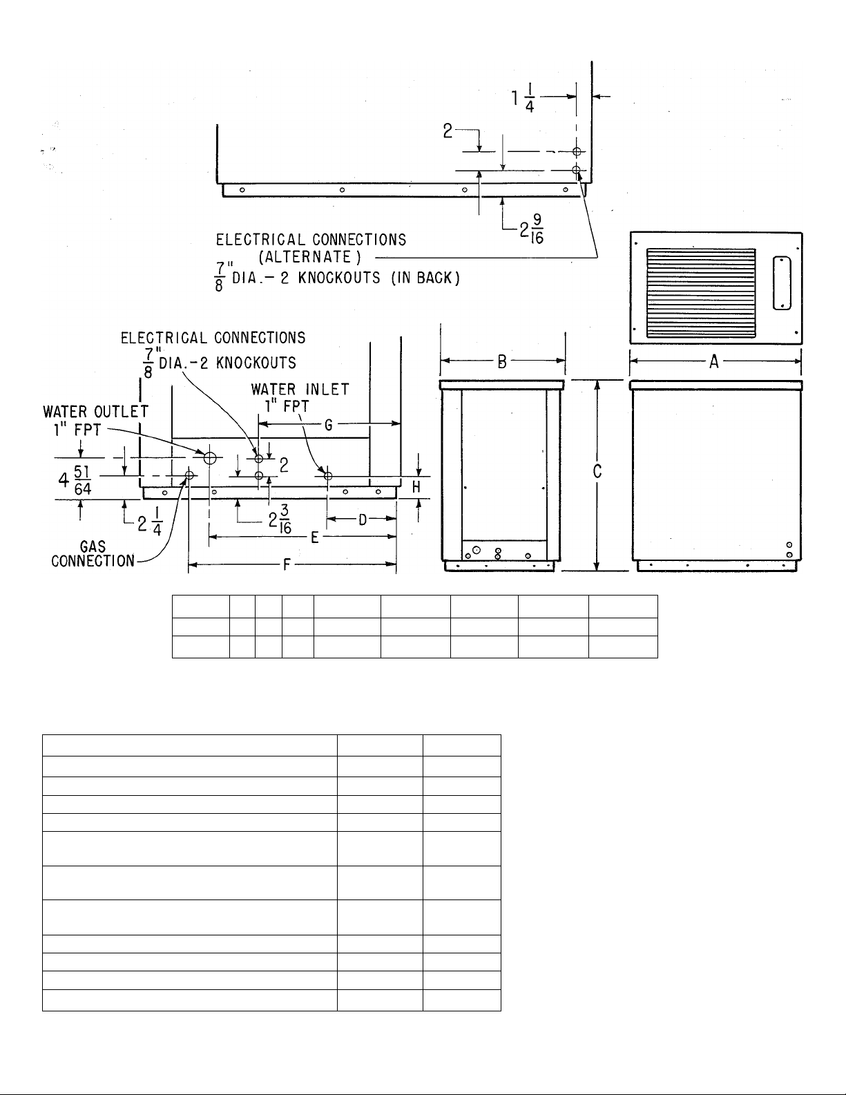
Model A
36-451
46 31 52
54-451 55
B
C
38 59
D
E
9-1/16 23-9/64
11-1/16 28-3/4
F
G
26-1/8 17-5/16
32-7/16
22
H
3-7/64
3-39/64
Cooling Capacity
Heat Input
Condenser Air Delivery
Water Flow (Min. Required)
Max. Frictional Loss Handled
by Chiller Pump
Max., Elevation of Coil
above Chiller Ft
Pump and Fan Drive
115V, 60 Cy., 1 Phase
Minimum Wire Size *
Refrigerant Type
Refrigerant Amount
Approximate Shipping Wt. Lb
EH 451
36-451
Btuh
Btuh
Cfm
Gpm
Ft Head 23 20
35,000 53,000
110,000 165,000
4,500 6,700
7.5 11
22
HP
AWG
1/3
14 *
54-451
22
1/2
12 *
717 717
Lb
18
750
- 2
31
1,125
^Satisfactory where distance, measured along
wire path, between unit and connection into
main panel does not exceed 100 ft. Where
distances are longer, wire sizes should be
increased accordingly.
Page 3

TABLE
Nominal
Pipe Size
Inches
3/4
1
1-1/4
* Note: Values shown in above table are for one direction only. The total length of pipe from chiller to coil
and return would be double the above table values. The above table applies to single unit installations only.
Figure 1
Polyethy ene Pipe Copper Pipe
Size 36
40'
150'
530'
Size 54
—
45' 140' 40'
145'
Allowable Distance* between Coil and Chiller
Size 36
35'
Size 54
—
360' 100'
SLEEPING
□
AVOID
OPEN
WINDOWS
QUARTERS
LIVING
AREA
Galvanized Pipe
Size 36
25'
90'
370'
AVOID
'ells"
□
GARAGE
Size 54
—
30 '
90'
□
GOOD
LOCATION
II. CONNECT CHILLED WATER LINES
A. MATERIALS
Refer to section on “Cold Weather Protection” at
the end of this instruction.
1. Piping
Figure 3
b. Copper - satisfactory substitute.
c. Galvanized - satisfactory substitute.
2. Fittings
a. Nylon - use when possible.
b. Brass - satisfactory substitute.
c. Galvanized - satisfactory substitute.
B. PIPE LENGTH AND DIAMETER
Table I shows maximum length of pipe of different
diameters that can be used between the pump dis
charge and the coil inlet and still maintain mini
mum allowable (design) water flow rate.
1. Multiply table values by two to obtain the total
length of pipe from chiller to coil ond return.
2. Length is measured along the pipe path and
therefore includes vertical distance between the
water coil and the chiller.
a. Polyethylene Plastic Pipe - use medium density
flexible pipe whose wall thickness approximates
Schedule 40 pipe (Commercial Standard CS 197-60).
Pipe must be virgin plastic. Do not use pipe manu
factured from re-claimed plastic.
- 3 -
3. Lengths shown in Table I are based on using a
total of eight elbows in the entire water line
(chiller to coil and return). Lengths are predicated
on the use of a Bryant matching water coil. For
greater distances use larger pipe or add a pump.
EH 451
Page 4

CLARIFICATION
On page 4 of this Instruction under Section III Electric Connections,
item 3 should read;
3. Provide a fused disconnect switch within sight of and
not more than 50 feet from the absorption unit.
FIL
C
Page 5

CORRECTION
Paragraph 6 on page 4 under Electric Connections should read as follows:
6. Disconnect pump electrical lead at terminal 7 in control box before energizing
unit when ready to check field wiring. Do not operate the pump dry.
Figure 6 on page 8 is NOT correct. Use the wiring diagram below instead of that on page
FOR EH 451
o
<
□
I
E
o
Ui
O
O)
c
Page 6

C. INSULATION
Ill, ELECTRIC CONNECTIONS
1. Insulate supply and return lines separately.
2. Material should be of good quality and be
covered with a good vapor barrier. Armaflex or
equivalent is recommended.
Wall thickness:
1/2" wall thickness - south of 40 ° N. latitude
3/8" wall thickness - north of 40° N. latitude
D. HEIGHT OF COIL
ABOVE ABSORPTION UNIT
Maximum vertical distance from chiller outlet to
top of coil is 22 feet for both sizes. For greater
heights, a greater pumping head is required. In
creasing the pipe size will not help.
E. WATER COIL CONNECTIONS
1. If coil is located in warm air stream, do not
connect polyethylene pipe directly to coil. Connect
a minimum of 24 inches copper or galvanized pipe
to both the coil inlet and outlet. Then connect the
plastic pipe to these nipples.
2. On installations where the outside piping
freezes and the coil is in a heated air stream, pre
cautions must be taken to provide for water expan
sion. The connecting polyethylene plastic pipe
acts as an expansion vessel if there is enough foot
age of this pipe in the heated space (space not
subject to freezing). The following table shows
the minimum lengths (total inlet and outlet) of
plastic piping of various diameters that are re
quired for both sizes of coils to provide adequate
expansion volume.
1. Make all electric connections in accordance
with the National Electrical Code and any local
ordinances or codes that might apply.
2. Provide a separate power supply for the air
conditioner.
3. Provide a fused disconnect switch within easy
reach of the absorption unit.
Size 36 - use 30 amp. Standard fuse or 15 amp.
fusetron.
Size 54 - use 35 amp. standard fuse or 20 amp.
fusetron.
4. The absorption unit is shipped fully wired from
the factory. Connection of 115V power and low
voltage connection to the thermostat control are
required in the field. Before proceeding, inspect
factory wiring for loose connections which may
have resulted during shipment.
5. Figure 6 is the Wiring Diagram. Do not fasten
power leads to hot tubing since wire insulation
could be damaged and a short circuit could result.
6. Disconnect pump electrical leads at terminals
6 and 7 in control box before energizing unit when
ready to check field wiring. Do not operate the
pump dry.
IV. GAS CONNECTIONS
Consult local gas company before making any gas
connections. In case of conflict with this instruc
tion, local requirements should be followed.
Nominal Pipe Size
Inches
%
1
Vk
Length of Plastic Pipe
in Feet
Size 36 Size 54
24
15
56
35
8.5 20
6.5
14.5
If the total plastic chilled water line footage in
the heated space is not as long as the minimum
values shown in the table, tee a vertical pipe of
sufficient volume into either of the coil connec
tions to provide for expansion, or the line should
be drained.
EH 451
Before selecting the size and type of pipe that is
to be used for installing the absorption unit, be
sure to check with local gas company for the
necessary information. The size of the gas pipe
to be used will depend upon the length of run and
the allowable pressure loss established by the
utility.
The gas connection to the unit is made at the com
bination regulator-shut-off. On the size 36 use a
V2" X 3" nipple and then a elbow. The supply
pipe enters the knockout on the other end of the
unit and will then be lined Up for final connection
if the nipple and elbow are used as described. On
the size 54 use aVi" x 2 "nipple and then a^/i" x
reducing ell and 3/4 inch pipe.
- 4 -
Page 7

A wrench-type shut-off valve should be installed
in the gas line within sight of, and convenient to,
the 451. Provide a ground joint union upstream of
the combination regular shut-off, and preferably
outside the unit.
Install a drip leg trap in the gas supply riser lead
ing to the unit. After gas pipe connections have
been made, purge the lines and check for leakage.
Use a soap and water solution or other such mater
ial.
Never use matches, candles, flame or other source
of ignition to check leakage.
PILOT
Light the pilot using the procedure outlined on the
Lighting Instruction Plate attached to generator.
The pilot flame should be soft blue in color. The
flame should be of sufficient length to provide good
impingment on the unimetal element of the Bryant
pilot. Flame should extend upward between the
carry-over ports of the two adjacent burners.
If the pilot flame does not have the appearance
described above, it may be adjusted by means of
the manual pilot shut-off valve which is equipped
with an adjustable screw. Turn the handle to the
full-open position and remove the screw cap on the
valve handle, thus exposing the adjustable screw.
Turn adjusting screw until flame has the desired
appearance. Replace screw cap.
V. CHARGING THE SYSTEM WITH WATER
Caution: Do not run the pump dry. Freezing condL
tions will not damage the pump; however, do not
attempt to operate the pump when chiller or chilled
water lines are frozen.
1. Turn off main manual gas shut-off valve.
2. Remove the filler cap from water chiller tank.
3. Disconnect line at chiller inlet. (When install
ing the chilled water lines, it is advisable to leave
this connection open until lines have been flushed).
4. Fill the tank with tap water by inserting a
garden hose into the filler tube about 12 inches
and running water into the chiller until it gushes
out around the hose. See Figure 4.
5. Start pump. Allow pump to operate until all
foreign matter has been flushed from the pipes.
Continue to supply water to the tank during this
cleaning period.
Note: If water does not circulate when the pump
is started, air may be trapped in the pump. Bleed
the air from pump through the 1/8" slotted head
bleed valve located on top of the pump discharge.
Open valve with screw driver. Close valve when
the trapped air is removed and water appears.
6. Turn off pump and hose. Make pipe connection
to chiller inlet.
7. Turn on hose and fill tank until water gushes
out around hose. Remove hose and replace filler
cap.
8. Start pump and while water is circulating, check
for leaks throughout the chilled water system.
9. Stop pump and remove filler cap. Insert one end
of a piece of water hose into the tank at least 12".
Insert a clean plastic or metal funnel in the other
end of the hose.
10. Start pump and pour carton of borax into funnel.
Flush borax into chiller with water from water
hose used for filling until tank over-flows. Remove
hose and replace filler cap. The package of borax
supplied is sufficient for chilled water systems
containing up to 20 gallons of water. For systems
- 5-
EH 451
Page 8

larger than 20 gallon capacity, add one-half (1/2)
package for each additional 10 gallon capacity or
fraction thereof. (Consult Bryant distributor for
estimating chilled water circuit capacities.)
11. The system is now ready to operate.
Note: The condenser fan belt is factory set and
is self-adjusting. No field adjustment is necessary.
VI. CHECK OUT AND OPERATION
1. Be sure main manual gas valve is off. Light
pilot as described on instruction plate.
2. Set thermostat to “cool”; set thermostat fan
switch to “auto”; set thermostat below room
temperature.
3. Turn on main electric switch to unit.
4. Check indoor fan operation by turning thermo
stat fan switch to “on” for continuous fan opera
tion. Move thermostat above room temperature and
observe that the indoor fan remains on.
5. To place the system in operation, open the main
manual gas valve, replace all panels, and set the
thermostat at the desired temperature.
To measure gas input, proceed as follows:
1. Adjust primary air if necessary.
2. Measure the gas input at the meter. Be sure all
other gas appliances are turned off. Input at the
burners may be increased or decreased slightly
by adjustment of the regulator in the burner supply
line.
Caution: Prolonged operation of the unit should
not be attempted with the panel off. The unit
may be run for short periods with the panel re
moved.
VIII. BALANCE THE SYSTEM
After the unit is in operation and the input has
been measured and adjusted to agree with the
rating plate requirements, balance the system.
Any approved method of checking the air flow over
the water coil may be utilized. Reference is made
to the Bryant Service Manual on Gas Air Condi
tioners for a review of standard methods.
High Temperature Cut-Off
The high temperature circuit includes a high tem
perature control located on the front of the gen
erator plus a high temperature relay (lockout
relay) located in the control box. If the generator
becomes overheated the contacts in the high temp
control open, causing the high temp relay to go
into lockout position. The gas valve closes, the
fans and pump stop, and they will not recycle until
the lockout relay is reset. To reset lockout relay
turn electric power off and then back on. Be sure
to locate and correct cause of high temp cut-out.
VII. ADJUST GAS INPUT
Gas input should agree with that shown on the
rating plate of the unit. The burners are equipped
with fixed orifices intended to give the correct
gas input with a manifold pressure of 3" w.c.,
using 1030 BTU natural gas of 0.63 S.G. Before
lighting burners, inspect to be sure that they have
not become dislodged or cocked during shipment
and installation.
IX. PURGE NON-CONDENSIBLES
Purging is accomplished through valve A on inlet
tank and Valve D on purge pot.
Operate unit for a minimum of 15 minutes. While
still operating, proceed as follows:
1. Attach adapter and purge line to Valve A.
2. Run purge line to bucket of water.
3. Remove cap and open valve A about 1/8 to 1/4
turn.
4. If non-condensibles are present, bubbles will
rise to the surface of the water in the bucket.
5. Leave Valve A open as long as bubbles rise
to the surface of the water. When non-condensibles
are removed the bubbles will cease as ammonia
will be absorbed into the water.
6. Close Valve A.
7. Open Valve D about 1/8 turn. Usually there
will be some solution trapped in the valve body,
and this solution will be released as soon as the
valve is opened.
EH 451 - 6
Page 9

8. If non-condensibles are present they will follow
the initial surge of solution. When solution re
appears in quantity, the non-condensibles trapped
in the purge pot have been released.
HA RD FI TT IM G-M AX .2 .
AD AP TER
9. Close Valve D.
The installation should now be complete.
FREEZING WEATHER PROTECTION
1. GAS AIR CONDITIONER
The Gas Air Conditioner has built-in freeze pro
tection sufficient to protect the chiller and pump
plus a small amount of external hard (non-plastic)
pipe as shown in Figure 5.
2. CHILLED WATER PIPES
If hard pipe is used (instead of plastic) for the
chilled water lines, be sure that adequate steps
are taken to prevent these pipes from bursting
when they are subjected to freezing temperatures.
3. BRYANT COIL
If the Bryant coil used with the absorption unit is
subject to freezing it must be protected. Consult
Bryant distributor for recommended procedure to
follow.
PL AS TIC P IP E
AD AP TER
HA RD FI TT IN G-M AX .2 ;
HA RD NI PP LE MA X. L ENG TH 4 "
PL AN VI EW
Figure 5
4. OPERATION AT FREEZING TEMPERATURES
If the air conditioning system is required to operate
under freezing conditions, consult your Bryant
Distributor for special procedures to follow.
-7
EH 451
Page 10

m
cn
PILOT iWITCH
Figure 6 - Unit Wiring Diagram - All Gases
POWER SUPPLY
5826301
i
1 i
115 VOLTS
Page 11

..„.„y
д
СП
Page 12

w
K
■t^
cn
0
o
o
o
Y G R
0
o
¿
MODEL 451
TERMINAL BLOCK
o
FAN
REMOTE
MOTOR
FAN RELAY
1
o
c)
FAN
K
) OJ
LIMIT
cj) c
)
-o o
RELAY
o
TH
TY PI CAL S EL F G EN ER ATI NG F URN AC E CON TR OL
115V
-------
PILOT
Q
P P
r
Page 13

TYPICAL
FURNACE WITH MULTI-SPEED TAPPED BLOWER
11 -
EH 451
 Loading...