

Page 1
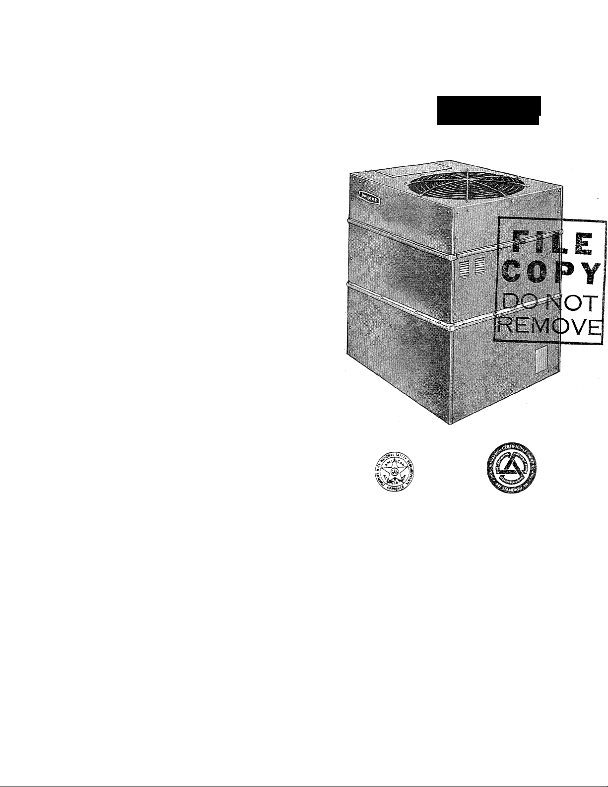
Installation Instructions
450D
Installation of the Model 450D Gas Air Conditioning
Absorption unit consists of the following steps:
I. Locate and mount absorption unit.
II. Connect chilled water lines.
III. Electrical connections.
IV. Gas connections.
V. Charge system with water.
VI. Check-out and Operation.
VII. Adjust gas input.
VIII. Balance system.
IX. Purge Non-Condensibles.
Each of the above steps is discussed in detail in this
instruction. Read entire instruction before starting in
stallation.
bPi|ont
I
ft
EPN 39450D1
Remove four shipping bolts holding absorption unit to
crate base before placing unit on permanent mounting
slab.
NOTE: Unit is shipped with condenser fan guard in
verted. Remove, place with convex side up and fasten.
I. LOCATE AND MOUNT^ABSORPTION UNIT
The absorption unit may be located at ground level'or
on the roof. Consult local codes for information con
cerning proximity to property lines, height above roof,
obstructions, etc.
A, MOUNTING BASE '
1. Use non-combustible materials.
2. Base should be large enough that unit will not
overhang.
3. Poured concrete slab, minimum 4” thick, recom
mended for ground installation. On roof installa
tions a metal plate is satisfactory. Leave 4” to
8” clearance between roof top and metal plate.
4. Mounting base should not obstruct drain holes
in base angle of unit. Drainage required to dis
pose of rain, melting snow, etc.
Certified in accordance cvith
A. G. A. APPROVED
B. CLEARANCES
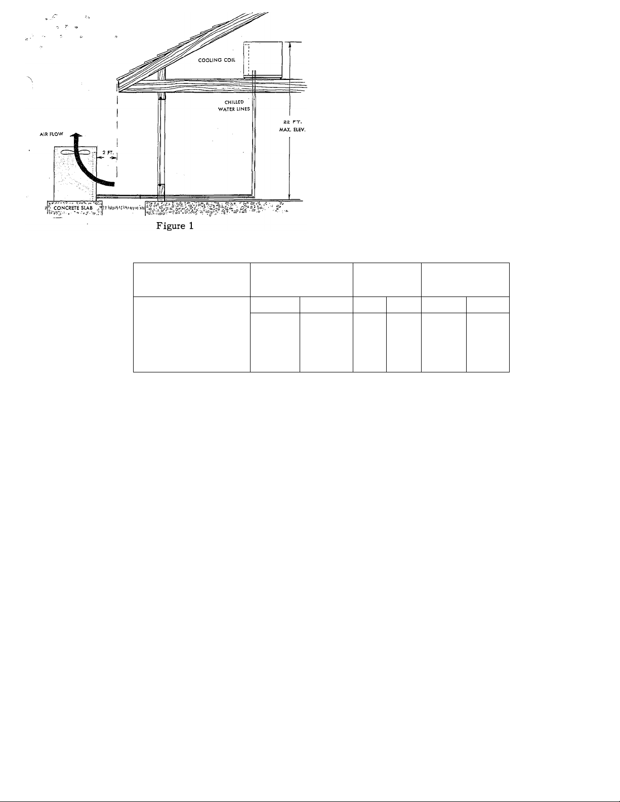
See Figures 1 and 2 for typical locations.
1. Absorption unit should have a minimum clearance
of 2 feet on all sides from any adjacent obstruc
tion.
2. Avoid overhead obstruction. Place unit at least
2 feet from plumb line of any overhang.
3. Avoid locating the unit where hot condenser dis
charge air can impinge on nearby obstruction and
mix with the cooler inlet air. This is particularly
important when two units are placed side by side.
A.R.I. standard 2d0—58.
CERTIFICATION APPLIES
ONLY WHEN USED WITH
PROPER COMPONENTS AS
SPECIFIED BY MANUFAC
TURER.
EH 450-2
CANCELS: EH 450-1
EFFECTIVE 12/1/63
Page 2
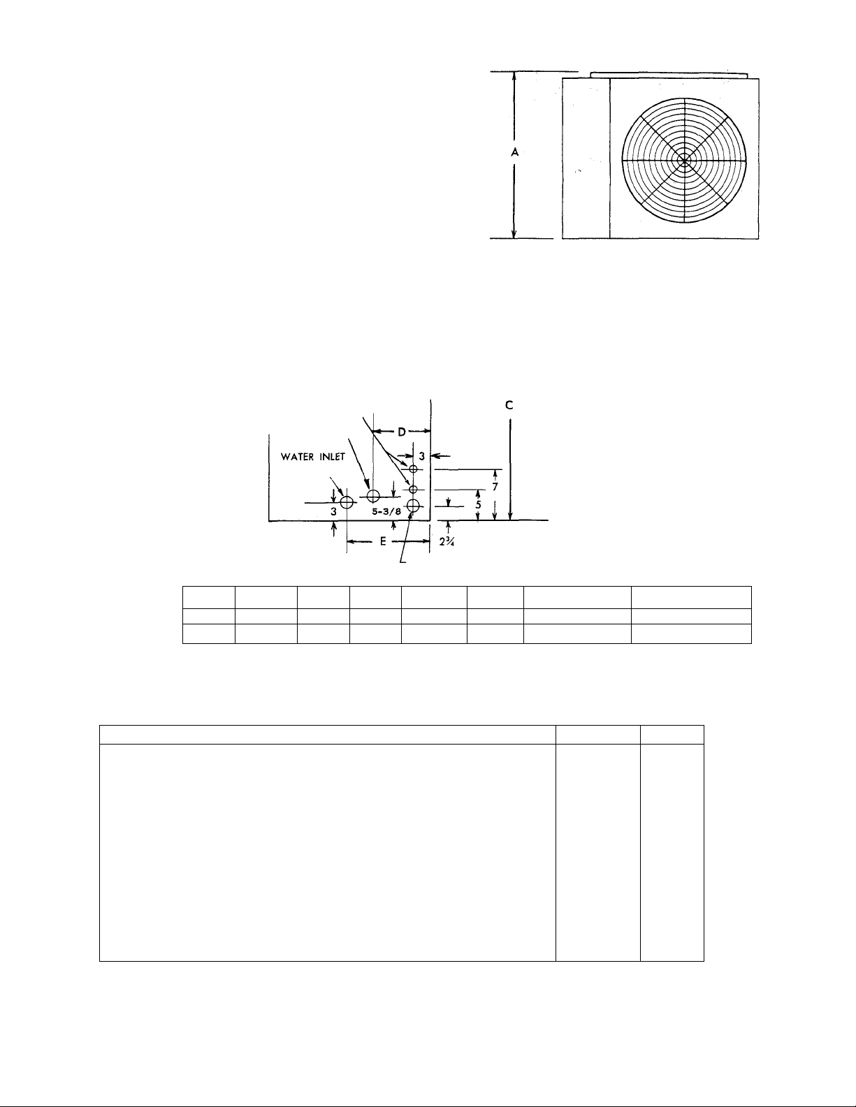
DIMENSIONS
RATINGS AND CAPACITIES
ELECTRICAL CONNECTION
WATER outlet'
O
GAS CONNECTION
SIZE
DIMENSIONS
MODEL
Cooling Capacity
Heat Input
Gas Connection Size
Condenser Air Delivery
Water Flow (Min. Required)
Max. Frictional Loss Handled by Chiller Pump
Max. Elevation of Coil Above Chiller
Condenser Fan Motor
115V, 60 Cy., 1 Phase
Pump
115V, 60 Cy., 1 Phase
Minimum Wire Size*
Refrigerant Type 717
Approximate Shipping Weight
*NOTE: Satisfactory where distance, measured along wire path, between unit and connection into main
panel does not exceed 100 ft. Where distances are longer, wire sizes should be increased ac
cordingly.
36
54 46-3/8
A
40-3/8 48 53
B
56
C D
60
5-5/16 15-1/2
7-1/16 18-3/8
Amount
E WATER INLET
1
1-1/4
36-450 D 54-450 D
BTUH 34,000 52,000
BTUH
INCHES
CFM
GPM 7.5
FT HEAD
FT 22 22
HP
HP
AWG 14 12
LB
LB
120,000
WATER OUTLET
1/2
4,500
23
1/3
1/8
24 42
1044 1544
1
1
180,000
3/4
6,700
11
20
1/2
1/8
717
EH 450
-2-
Page 3
SLEEPING
AVOID
OPEN
WINDOWS
QTRS.
TABLE I . DISTANCE BETWEEN COIL AND CHILLER
LIVING
AREA
AVOID OVERHANG
Figure 2
□
AVOID
“ELLS"
GARAGE
7 PREVWUNG
WIND
GOOD
LOCATION
NOMINAL PIPE SIZE POLYETHYLENE
3/4
1
1-1/4
M/2
NOTES Values shown are for one direction only. Multiply by two to obtain the total length
of pipe from chiller to coil and return.
* Pipe lengths exceeding 75 feet may require additional chilled water additive. (See Section V,
this instruction.
II. CONNECT CHILLED WATER LINES
A. MATERIALS
Refer to section on “Cold Weather Protection” at the
end of this instruction.
1. Piping
a. Polyethylene Plastic Pipe - use medium density
flexible pipe whose wall thickness approximates
Schedule 40 pipe (Commercial Standard CS 197-
60). Pipe must be virgin plastic. Do not use
pipe manufactured from re-claimed plastic.
b. Copper - satisfactory substitute.
c. Galvanized - satisfactory substitute.
2. Fittings
a. Nylon - use when possible.
b. Brass - satisfactory substitute.
c. Galvanized - satisfactory substitute.
Feet
36 54
40
—
150 ^ 45
530 ^
145 *
1585 ^ 310 *
B. PIPE LENGTH AND DIAMETER
Table I shows maximum length of pipe of different
diameters that can be used between the pump dis
charge and the coil inlet and still maintain minimum
allowable (design) water flow rate.
1. Multiply table values by two to obtain the total
2. Length is measured along the pipe path and
3. Lengths shown in Table I are based on using a
COPPER
36
35
140 ^
360 ^
815a^
Feet
54 36 . 54
—
40
100^
205^
GALVANIZED
Feet
25
90 ^
—
30
370 ^ 90 ^
770 ^ 190 ^
length of pipe from chiller to coil and return.
therefore includes vertical distance between the
water coil and the chiller.
total of eight elbows in the entire water line
(chiller to coil and return). Lengths are predi
cated on the use of a Bryant matching water coil.
For greater distances use larger pipe or add a
pump.
EH 450
- 3 -
Page 4

II. CHILLED WATER LINES (cont’d.)
C. INSULATION
1. Insulate supply and return lines separately.
2. Material should be of good quality and be covered
with a good vapor barrier. Armaflex or equivalent
is recommended.
Wall thickness:
1/2” - south of 40° N. latitude
3/8” - north of 40° N. latitude
D. HEIGHT OF COIL ABOVE ABSORPTION UNIT
Maximum vertical distance from chiller outlet to top
of coil is 22 ft. for both sizes. For greater heights,
a greater pumping head is required. Increasing the
pipe size will not help.
E. WATER COIL CONNECTIONS
1. If coil is located in warm air stream, do not con
nect polyethylene pipe directly to coil. Connect
a minimum of 24” copper or galvanized pipe to
both the coil inlet and outlet. Then connect the
plastic pipe to these nipples.
2. On installations where the outside piping freezes.
and the coil is in a heated air stream, precau
tions must be taken to provide for water expan
sion. The connecting polyethylene plastic pipe
acts as an expansion vessel if there is enough
footage of this pipe in the heated space (space
not subject to freezing). The following table
shows the minimum lengths (total inlet and out
let) of plastic piping of various diameters that
are required for both sizes of coils to provide
adequate expansion volume.
Length of Plastic Pipe
Nominal Pipe Size
3/4
1
1-1/4
1-1/2
Unit Size
36
54
24 56
15
8.5
35
20
6.5 14.5
If the total plastic chilled water line footage in
the heated space is not as long as the minimum
values shown in the table, tee a vertical pipe of
sufficient volume into either of the coil connec
tions to provide for expansion, or the line should
be drained.
F. LEAK CHECK
Water should be added to the chiller, pump operated,
and each joint checked for leakage. Do not add the
chemical additive (shipped in container stored in
chiller tank) to the water until after leak check is
complete. It is convenient to check for leakage
when charging the system with water. See Section V.
III. ELECTRIC CONNECTIONS
(»• J
1. Make all electric connections in accordance with the
National Electrical Code and any local ordinances
or codes that might apply.
2. Provide a separate power supply for the air condi
tioner.
3. Provide a fused disconnect switch within easy reach
of the absorption unit.
Size 36 -use 30 amp. standard fuse or 15 amp. fusetron. Size 54-use 35 amp. standard fuse or 20 amp.
fusetron.
4. The absorption unit is shipped fully wired from the
factory. Connection of 115V power and low voltage
connection to the thermostat control are required in
the field. Before proceeding, inspect factory wiring
for loose connections which may have resulted
during shipment.
5. Figures 3 and 4 are wiring diagrams.
IV. GAS CONNECTIONS
Consult local gas company before making any gas con
nections. In case of conflict with this instruction,
local requirements should be followed.
Before selecting the size and type of pipe that is to be
used for installing the absorption unit, be sure to check
with local gas company for the necessary information.
The size of the gas pipe to be used will depend upon
the length of run and the allowable .pressure loss
established by the utility.
A wrench-type shut-off valve should be installed in the
gas line within sight of, and convenient to, the 45OD.
Provide a ground joint union inside the unit case and
upstream of the main gas supply regulator.
Install a drip leg trap in the gas supply riser leading
to the unit.
After gas pipe connections have been made, purge the
lines and check for leakage. Use a soap and water solu
tion or other such material. Never use matches, candles,
flame or other source of ignition to check leakage.
PILOT
The pilot assembly is equipped with a fixed orifice
designed to give correct input at 3” w.c. gas pressure.
The pilot supply line is equipped with a regulator and
factory adjustment of this regulator should be satis
factory in all cases. The manual shut-off valve for the
pilot gas supply is incorporated in this regulator.
To light pilot:
1. Shut off main electric power and remove lower
front panel from unit.
2. Be sure manual shut-off valve to the burners is
closed. Also close the manual shut-off valve to
the pilot.
3. Wait five minutes.
4. Open manual shut-off valve to pilot, and light
pilot with taper through the pilot hole on front of
generator.
EH 450
-4-
Page 5

m
X
o
Figure 3 - Wiring Diagram - City Gases
Page 6

m
X
41».
Cn
O
Figure 4 - Wiring Diagram - LP Gases
Page 7

REMOTE
FAN RELAY
FAN
MOTOR
115V
PILOT
EH 450
FAN
K
) (>
LIMIT
c5 C
)
RELAY
0 0 6 6
X Y G R
MODEL 450
TERMINAL BLOCK
o o o o
TYPICAL SELF GENERATING FURNAGE CONTROL
Wiring Diagram Showing Thermostat and Model 450 Terminal Block with Typical Furnace Installation.
- 6a -
—^
TH
^
___
n
P P
Page 8

TYPICAL
FURNACE WITH MULTI-SPEED TAPPED BLOWER
Wiring Diagram
EH 450
6b-
Page 9

?. CHAliGING THE SYSTEM WITH WATER VI. CHECK-OUT AND OPERATION
Caution: Do not ran the pump dry. Freezing conditions
will not damage the pump, but do not attempt to operate
pump when chiller or chilled water lines are frozen.
1. Remove belt from condenser fan.
2. Turn off main manual gas shut-off valve.
3. Remove top cover from water chiller tank. Remove
container of chilled water additive stored in tank.
4. Fill tank with tap water until distribution pan at top
is covered with water. A garden hose is useful for this
operation.
5. Disconnect line at chiller inlet. (When installing the
chilled water lines, it is advisable to leave this con
nection open until lines have been flushed). Start pump.
Allow pump to operate until all foreign matter has been
flushed from the pipes. It is recommended that the gar
den hose be used to supply water continuously to the
tank during this cleaning period.
6. Turn off pump. Make pipe connection to chiller inlet.
7. Refill the chiller tank with tap water and remove
garden hose.
8. Start pump and, while water is circulating, check for
leaks throughout the chilled water system.
9. Adjust the water level in the chiller while the pump
is still running. This is accomplished by removing the
water level pipe cap as shown in Figure 5. When water
ceases to drain, the level is properly adjusted. Replace
the drain cap. Turn off the pump. (If no water flows
when the drain cap is removed, refill the tank and repeat
the draining operation to adjust the water level).
1. Be sure the condenser fan guard has been installed
properly.
2. Be sure main manual gas valve is off. Light pilot as
described on instruction plate.
3. Set thermostat to “Cool”; set thermostat fan switch
to “Auto”; and set thermostat below room temperature.
4. Turn on main electric switch to unit.
5. Observe condenser fan operation; adjust belt tension
if necessary.
6. Check indoor fan operation by turning thermostat fan
switch to “on” for continuous fan operation. Move
thermostat above room temperature and observe that the
indoor fan remains on.
7. To place the system in operation, open the main
manual gas valve, replace the front panel (all panels),
and set the thermostat at the desired temperature.
High Temperature Cut-Out. The high temperature circuit
includes a high temperature control located on right
side of generator plus a high temperature relay (lockout
relay) located in control box. If the generator becomes
overheated the contacts in the high temp control open,
causing the high temp relay to go into lockout position.
The gas valve closes, the fans and pump stop, and
they will not recycle until the lockout relay is reset.
To reset lockout relay turn electric power off and then
back on. Be sure to locate and correct cause for high
temp cut-out.
10. Add chilled water additive (packed in chiller tank).
The package supplied is sufficient for chilled water
systems containing up to 20 gallons of water. For
systems larger than 20 gallon capacity, add one-half
(1/2) package for each additional 10 gallon capacity or
fraction thereof. (Consult Bryant distributor for estimat
ing chilled water circuit capacities).
11. Replace the lid on the chiller tank.
12. Replace the condenser fan belt. Adjust tension.
13. The system is now ready to operate.
OPERATING LEVEL
DRAIN
VII. ADJUST GAS INPUT
Gas input should agree with that shown on the rating
plate of the unit. The burners are equipped with fixed
orifices intended to give the correct gas input with a
manifold pressure of 2.6" w.c., using 1030 BTU natural
gas of 0.63 S. G. Before lighting burners, inspect to be
sure that they have not become dislodged or cocked
during shipment and installation.
To measure gas input, proceed as follows:
1. Adjust primary air if necessary.
2. Measure the- gas input at the meter. Be sure all
other gas appliances are turned off. Input at the
burner's may be increased or decreased slightly
by adjustment of the regulator in the burner
supply line.
Caution: Prolonged operation of the unit should not be
attempted with the front panel off. The unit may be ran
for short periods with the panel removed.
- 7 -
Page 10

VIII. BALANCE THE SYSTEM
After the unit is in operation and the input has been
measured and adjusted to agree with the rating plate
requirements, balance the system.
Any approved method of checking the air flow over the
water coil may be utilized. Reference is made to the
Bryant Service Manual on Gas Air Conditioners for a
review of standard methods.
IX. PURGE NON-CONDENSIBLES
Purging is accomplished through Valve “A” as shown
in Figure 6, and at Valve “D” at the purge pot.
Operate unit for a minimum of 15 minutes. While still
operating, proceed as follows:
1. Open Valve "D” at purge pot about 1/8 turn. Solu
tion trapped in valve body will appear as soon as valve
opens. If non-condensibles are present they will follow
this surge of solution. When solution re-appears in
quantity the non-condensibles trapped in the purge pot
will have been released. Close Valve “D”.
2. Attach purge line to Valve “A” as shown in Figure 6
and place free end of purge line in bucket of water.
3. Open Valve “A” about 1/8 to 1/4 turn. If non
condensibles are present, bubbles will rise to the
surface of the water in the bucket.
4. Leave Valve “A” open until the bubbles cease and
ammonia starts to escape through the purge line.
Presence of ammonia will be clearly indicated by a
sharp, crackling sound (the sound of absorption). Close
Valve “A”.
The installation should now be complete.
HARD FITTII^G-MAX.2,
ADAPTER
PLASTIC PIPE
ADAPTER
HARD FITTING-MAX.2;
HARD NIPPLE MAX. LENGTH 4"
PLAN VIEW
Figure 7
Figure 6
FREEZING WEATHER PROTECTION
1. GAS AIR CONDITIONER
The Gas Air Conditioner has built-in freeze protec
tion sufficient to protect the chiller and pump plus a
small amount of external hard (non-plastic) pipe as
shown in Figure 7.
2. CHILLED WATER PIPES
If hard pipe is used (instead of plastic) for the chil
led water lines, be sure that adequate steps are taken
to prevent these pipes from bursting when they are
subjected to freezing temperatures.
Consult Bryant Distributor.
3. BRYANT COIL
If the Bryant coil used with the absorption unit is
subject to freezing it must be protected. Consult
Bryant distributor for recommended procedure to
follow.
4. OPERATION AT FREEZING TEMPERATURES
If the air conditioning system is required to operate
under freezing conditions, consult your Bryant Dis
tributor for special procedures to follow.
EH 450
- 8-
 Loading...