

Page 1
i nsta I lation i nstructions
COUNTERFLOW GAS-FIRED
FORCED-AIR FURNACE
Before installing the fiimace, refer to "Procedure for GasFired Furnaces” (packaged with the equipment) for informa
tion concerning combustion, venting, piping, and other stan
dard installation practices. Further reference is made to the
ciurrent edition of the American National Standard Z223.1
National Fuel Gas Code.
Each furnace is shipped from the factory completely assem
bled with multispeed direct-drive blower and wired ready for
counterflow indoor heating installation only. All sizes
feature a printed-circuit board control center with easy-toread, low-voltage terminal strip to ensure proper connec
tions.
The efficiency rating of the furnace is a product thermal
efficiency rating determined under continuous operating
conditions independent of any installed system.
CAUTION: Do not install furnace in a corrosive or contami
nated atmosphere. Make sure all combustion and circulating
air requirements listed in "Procedure for Gas-Fired Fur
naces” are adhered to, in addition to, all local codes and
ordinances.
The design of the counterflow gas-fired furnace is A.G.A. cer
tified for installation on combustible flooring (with optional
floor base), in alcoves, basements, closets, or utility rooms.
This furnace line is
mobile home, recreation vehicle, or outdoors.
TABLE i-CLEARANCES (In Inches)
Sizes
Sides—Single-Wall Vent
Type-B Double-Wall Vent
Back
Top of Plenum
Vent Connector—Single-Wall
Front—Combustion Air
Service
INTRODUCTION
not A.G.A. certified for installation in a
050 075 thru 150
1
0
1
1
0 0
1 1
Type-B Double-Wall
6 6
1
6 6
1
30 30
Cancels: 40396DP5-A
and 40396DP6-A
I ! '
I" r,
----- ! .- i
40396DP7-A
1/15/80
Ipip Í
A78593
Figure 1—Model 396G036075 With Optional
Vent Damper Installed
Installation comprises the following:
I. Inspection
II. Location, Ventilation, and Air for Combustion
III. Gas Piping
IV. Venting
All of the above steps are covered in general by the like-num
bered sections of the "Procedure for Gas-Fired Furnaces”
booklet packaged with the furnace; therefore, these Installa
tion Instructions will contain only supplementary informa
tion applicable to installing the furnace.
In addition, the following sections deal specifically with in
stallation of the 396G:
V. Supply-Air Plenum Installation
VI. Electrical
VII. Sequence of Operation
VIII. Filter
IX. Startup and Adjustment
X. Care and Maintenance
For accessory installation details, refer to applicable in
stallation literature.
RDP Company, Division of Carrier Corp.
V. SUPPLY-AIR PLENUM INSTALLATION
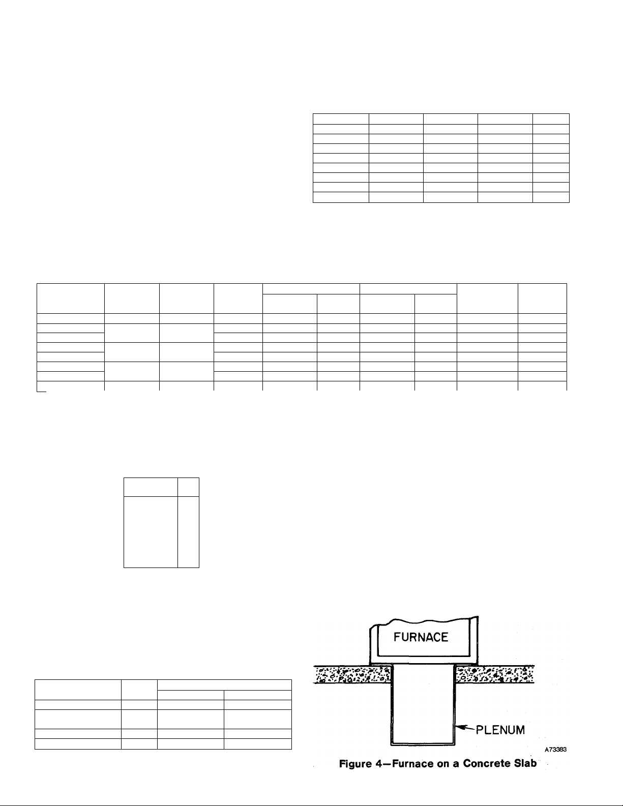
A. Installation on a concrete slab
1. See Figure 2 for dimensions and location of supply-air
opening in furnace bottom.
2. Construct hole in floor per dimensions in Figure 3 eind
Table IV.
3. Place plenum and furnace as shown in Figure 4.
B. Installation on a combustible floor
1. Read Installation Instructions packaged with combusti
ble floor base.
2. Cut and frame hole in floor per dimensions in Table I of
Installation Instructions packaged with combustible floor
base. If this requires cutting of a floor joist, tie ends of cut
joist into adjacent joists so that proper floor support will be
maintained.
3. Assemble and install combustible floor base per instruc
tions packaged with base.
4. When completed, combustible floor base, plenum, and
furnace (or coil casing when used) should be installed as
shown in Figure 6.
Page 2
г/
TABLE ll-DIMENSIONS (in Inches)
1Л
ir
ф
пг
.Q..
Г'
KNOCKOUT
ДиХ GAS
INLET
A78595
Size
024050 14-3/16
000075
036075
000100 .
. 048100
000125
048125
060150
Figure 2—Dimensional Drawing
TABLE lil-RATINGS AND PERFORMANCE*
Size
024050 50,000 40,000 45-75 0.50 620
000075
036075 45-75 0.50 925
000100 100,000 80,000
048100
000125 125,000 100,000 70-100 0.20
048125
060150 150,000 120,000 55-85 0.50 1850
Input
Btuh
75,000 60,000 70-100 0.12 700
Bonnet
Capacity
Btuh
Temp
Rise
Range
70-100
60-90 0.50 990
60-90 0.50 1235
Heating Cooling
Ext Static
Pressure
0.20 870
Ft3/Min
1090
*The above ratings are certified for altitudes to 2000 ft. For elevations above 2000 ft, reduce ratings 4% for each 1000 ft above sea level.
A
IT-1/2
. 17-1/2
17-1/217-1/2
21
21 19-3/8
24-1/2
Ext Static
Pressure Ft3/Min
0.5
—
0.5 1255 1/3-SP
— —
0.5 1630
—
0.5 1620
0.5
D
12-9/16
15-7/8
15-7/8
15-7/8
15-7/8
19-3/8
22-13/16
800
— 1/10-SP 146
— 1/5-SP 185
2075
E Vent
12-11/16
16- 4
16
16 5
16
19-1/2
19-1/2
23 6
Motor
HP&
Type
1/3-SP 127
1/5-SP 161
1/2-PSC
1/2-PSC
1/2-PSC 225
Approx
Ship.
Weight
155
168
186
4
4
5
5
5
HOLE IN
FLOOR
3
Figure 3 — Floor Opening for
Concrete Siab
TABLE IV —OPENING DIMENSIONS
Furnace
Size
024050 13-1/8 19-5/8
000075, 036075,
000100, & 048100
000125 & 048125 19-7/8 19-5/8 20-15/16
060150
These dimensions apply when a Model 518A Evaporator Coil casing
is to be installed.
A В
16-7/16
23-7/16 19-5/8
Heat-Only Heat/Cool*
19-5/8
20-15/16
20-15/16
20-15/16
VI. ELECTRICAL CONNECTIONS
A. Line-Voltage Wiring
IMPORTANT: Before proceeding with the electrical connec
tions, make certain that voltage, frequency, and phase cor
respond to that specified on the unit rating plate. Also, check
to be sure that the service provided by the utility is sufficient
to handle the additional load imposed by this equipment. Re
fer to the unit rating plate for equipment electrical require
ments.
CAUTION: Do not connect aluminum wire between discon
nect switch and furnace.
See Figure 8 for wiring diagram showing the proper field
high- and low-voltage wiring. Make all electrical connec
tions in accordance with the National Electrical Code and
any local codes or ordinances that might apply.
-2-
Page 3
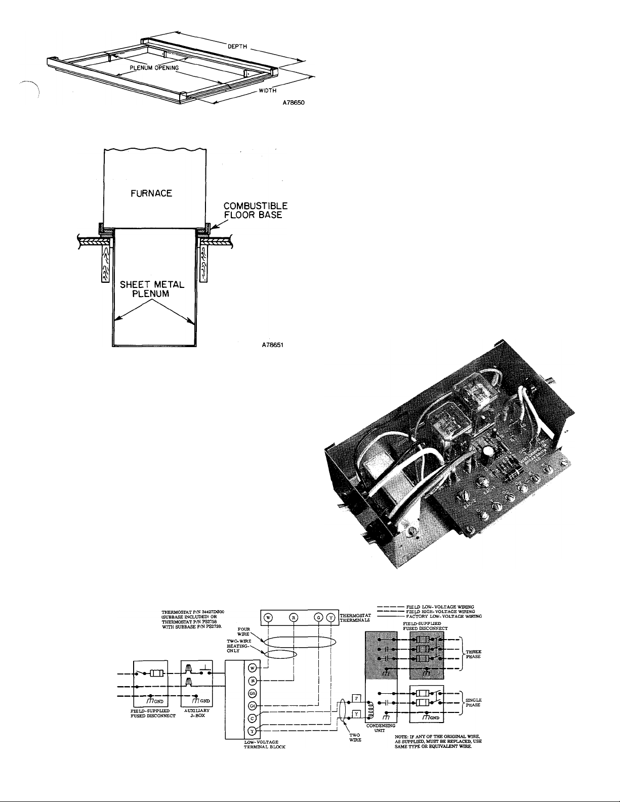
Figure 5—Combustible Floor Base
Set the thermostat heat anticipator at 0.5 for a furnace with a
BDP Model 646A Gas Valve; 0.6 for a furnace with an Essex
Model 242 Gas Valve; 0.2 when a Model 997A Vent Damper is
installed — no matter which of these gas valves is used. If
additional controls are connected in the thermostat circuit,
their amp draw must be added to this setting. A failure to
make this setting will result in improper operation of the
system.
For accurate reading, check the amp draw at the ther
mostat with an ammeter. A failure to make this setting
will result in improper operation of the system.
The room thermostat should be located where it will be in
the natural circulation path of room air. Avoid locations
where the thermostat would be exposed to cold-air infiltra
tion, drafts from windows, doors, or other openings leading
to the outside, or exposure to air currents from warm- or
cold-air registers; or to exposure where the natural circula
tion of the air is cut off—such as behind doors, above or
below mantels, shelves, etc.
The thermostat should not be exposed to heat from nearby
fireplaces, radios, televisions, lamps, or rays from the sun.
Nor should the thermostat be mounted on a wall containing
pipes or warm-air ducts, or a flue or vent that could affect its
operation and prevent it from properly controlling the room
temperature. Any hole in the plaster or panel through which
the wires pass from the thermostat should be adequately
sealed with suitable material to prevent drafts from affect
ing the thermostat.
Figure 6—Furnace, Plenum, and
Base Installed on a Combustible Floor
Use a separate fused branch electrical circuit for this furnace.
A disconnecting means must be located within sight of, and
readily accessible to, the furnace. In some areas, the imit door
switch may qualify as the disconnecting means.
WARNING: The furnace must be electrically grounded in
accordance with local codes, the National Electric Code, and
ANSI C1-1978. Do not use gas piping as an electrical ground.
If line-voltage wiring to the unit is encased in a nonmetallic
sheath, connect the incoming ground wire to the grounding
wire inside the furnace J-box. If metallic conduit is used, it
will serve as the ground.
B. Low-Voltage Wiring
Make field low-voltage connections at the low-voltage ter
minal strip. See Figure 8.
NOTE; Use AWG No. 18 “color-coded” copper thermostat
wire for lengths up to 100 ft. Above 100 ft, use AWG No. 16
wire.
A79077
Figure 7—Printed-Circuit Control Center
Figure 8—Heating and Cooling Application Wiring Diagram
-3-
A78461
Page 4

é. Blower Control Center
Each furnace features a printed-circuit control center. This
will aid the installer and serviceman when installing and
servicing the unit. See Figure 7. A low-voltage terminal
board is marked for easy connection of field wiring.
VII. SEQUENCE OF OPERATION
NOTE: The wiring diagram shown in Figure 9 covers heat
ing-only and Figures 10 and 11 cover heating/cooling.
A. Heating
Gas and electrical supplies must be turned on at the furnace.
NOTE: When power is applied to heat relay coil 2A in the
control circuit, the normally closed contacts in the blower
circuit will open.
1: BDP 646 and Robeiishaw 7000 BKER Gas Valves
(IID Models)
When the thermostat “calls for hëàt,” thé control Circuit is
clpsèd between terminals R and W- JPowef from transformer
1À through fusible link liC and limit switches 7Hi/7H2
energizes the pilot valve portion of automatic gaS valve 5F
and pilot igniter 6F. The pilot valve opens, perinitting gas
flow to the pilot burner wheré it is ignited.
The pilot valve portion of automatic gas valve 5F is a
solenoid consisting of a “pick” and a “hold” coil. Both the
“pick” and the “hold” coils must be energized to open the
valve, but only the “hold” coil must be energized to këep it
open.
Figure 9—Line-to-Line Wiring Diagram for Sizes
050 thru 150 (match-lit pilot) Natural Gas & LPG 050 thru 150 IID LPG
LEGEND
ÍA^TranSfdFrñer 1l5/24
2A-Relay-Heat (SPST-N.G.)
2F-Relay-Cooi (DPDT)
3D-Blower Motor
4A-Run Capacitor
5E-GaS Valve
....................................
5F-Gas, Valye (Two-Circuit)
6C1-Printed-Circuit Board
6C2-Pilot igniter and Flame Sensing
6C3-Lockout Timer Module
6F-Pilot Igniter
6H-Safety Pilot (Flame Sensing)
7H1-Limit Switch (SPST-N.C.)
7H2-Auxiliary Limit Switch (SPST-N.C.;
Manual Reset
9A-Summer/Winter Switch
9G-Blower Door Switch (SPST-N.C.)
IIA-Resistor
11C-Fusible Link
Figure 10—Line-to-Llne Wiring Diagram for Sizes
050 thru 150 IID Natural Gas
Page 5

Whén thè pilot flame is established, pilot 6ÌÌ switches iiè
contacts in approximately 40 to 60 secohcis, energizing thè
main valve portion of gas valve 5F and deenergizing pilot
igniter 6F and the “pick” coil portion of the pilot solenoid in
gas valve 5F.
The main valve poirtibii of gas valve 5F is heat motor operated;
therefore, after approximately 10 seconds, (Robertshaw Valve
opens instantly), this portion of the valve opens, permitting
gas flow to the main burners where the gas in ignited by pilot
6H.
2. BDP 647 and Essex 242 iSas Valves
(Match-Lit Models)
The furnace pilot must bè lit. to energize the thermal
magnet circuit of gas valve 5E; thus permitting gas flow tb
thè remaining portion of the valve.
tABlE V — PILOT GAS GONSUMPTlÓ^J
.
........
Pilot
ËDP 733B
Penri
Penn
Gas BtüH
......
Nat
Nat
Prop.
........
875
1250 3.5
690 10.5
..........
In; wc
5;0
Wheii thé thermostat “calls for heat;” the control circuit is
closed bet\veeh terminals R and W, Power froni transformer
ÍÁ through fusible link Í1C and limit sw;itches 7H1/7H2
energizes gas valve 5É, causing the valve tb Open ând per
mitting gas flow to thé main burners, wherè it is ignited bÿ
the pilot. Some furnaces af e equipped with a step opening gab
valve. When the burners first i^ite, the flame will be low and
soft. In approximately 15 seconds the valve will fully open and
the burner uamé will be normal size.
3. Essex 242 Gas Valve (HD Models) LPG
When the thermostat "calls for heat,” the control circuit is
closed betwëèü terminals R ând W. Power from transfofniër
l ihrotigh Rigibiê lüik íiC, limit switches 7HÍ & 7ÍÍÍ, âhd
through lockout tifhëf ínbdüle 6CÍ3, ëhergièës pilot igniter 8CÍ2
and the pilot valve part of gas valve 5F, causing the valve to
Open and to ignite the pilot. When the pilot flame is estab
lished, thë pilot Sensing probe energizes the main gas valve,
permitting gas flow, to thè main burners. The pilot electrode
continues sparking for approximately 5 to 10 seconds after the
pilot flame has beeii established.
If the pilot flamè iS not proven withiii approximately 30
seconds; lockout module 6G3 opens, deenèrgizing gaS valve 5F
and stopping thé gas flo\v to thë pilot; The. lockout module
remains Open until it is manually reset bÿ interrupting thé
low-voltagé or high-voltage circuit for approximately 30
Seconds.
3. Blower Circuit
With power through thé solid-state time-delay circuit on
printed-circuit board 6C1 and heat relay 2A; blower motor
3
d is energized on heating speed approximately 75 seconds
after gas valve 5E has been energized (or the pilot flame haS
been proven in the case of BDP 646 Gas Valve 5F).
4; Limit Control
If the furnace overheats for any reason, limit control 7H1
switches; breaking the circuit to automatic gas valve 5E or
5F. The gas valve closes immediately, stopping gas flow to
the main burners and the pilot. In addition; blower motor 3D
continues to operate because heat relay 2A is deenergized to
cool down the furnace.
Manual reset auxiliary limit switch 7H2 is located on the
top right-hand corner df the furnace. In the event of blower
motor failure, this switch breaks the electrical circuit to the
gas valve, stopping gas flow to the main burners; The switch
must be manually reset after the blower motor has been rè^
placed.
Fusible link iiC is provided in the transformer ÌA secondary
Circuit as protection from overheating Conditions in the
vestibule area of the fumacè. Should this condition exist,
the fuse opens and deenergizes gas valve 5E or 5F and heat
relay 2A, stopping the gas flow to the burners and starting
blower motor 3D.
When the therrhostat is satisfied, the circuit between R and
W is broken, deenergizing automatic gas valve 5E or 5F,
pilot 6H (when used), and the solid-state time-delay circuit
on printed-circuit board 6C1. The gas flow stops immediately
to the pilot and rtiain burners with the BDP 646 or Robertshaw
7000 BKER Gas Valves, and to the main burners only with the
BDP 647 and Essex 242 Gas Valves. After approximately 105
seconds, heat relay 2A is energized and blower motor 3D stops.
Somé furnaces are equipped with a step opening gas valve.
When the burners first ignite, the flame will be low and soft.
In approximately Ì5 seconds, the valve will fully open and the
burner flame will be nOrmâl size.
B. Vent Damper (when used)
When the thermostat “calls for heat,” the control circuit is
closed between terminals R and W. Power from transformer
lA energizes the damper motor relay coil, causing the nor
mally closed relay contacts to open, deenergizing the
damper motor and causing the spring-loaded damper to
open. When thé automatic vent damper is open, the circuit is
completed to automatic gas valve 5E or 5F. The sequence
from this point on is the same as that for heating.
When the thermostat is satisfied, the circuit between R and
W is broken, deenegizing the damper motor relay, and caus
ing the relay contacts to close. The daiiiper motor starts and
closes the damper.
C. Cooling (cooling models only)
When the thermostat “calls for cooling,” power from trans
former lA energizes thé condensing Unit cOntâctbr, Cooling
relay coil 2F, Closiiig its contacts and èhêrgizing blower mo
tor 3Î3 Oh its cooling Speed, it continues tO operate until thé
thermostat is satisfied.
When the thermostat is satisfied, the circuit to terminal Gc
is broken, deenergizing cooling relay coil 2F which, in turn,
opens its contacts, stopping blower motor 3D.
Vili. FILTER ARRANGEMENT
The two factory-supplied filters are shipped in the blower
compartment. After the return-air duct has been connected
to the fiurnace, install the filters in a V-formation inside the
return air plenum. See Figure 12.
WARNING: Never operate unit without a filter or v/ith filter
access door removed.
RETURN-AIR
PLENUM
Figure 12—Position of Filters
INSTALLATION
POSITION
(DF FILTERS
Page 6

IX. STARTUP AND ADJUSTMENT
In addition to the following information, refer to "Procedures
for Gas-Fired Furnaces” packaged with the unit.
NOTE: There is a switch located in the blower compartment
that breaks the electrical power supply when the blower ac
cess door is removed. Be sure blower access door is properly
installed.
CAUTION: This furnace is equipped with a fusible link in
the vestibule area that will melt if an overheating condition
caused by an inadequate combustion air supply or improper
venting practices develops.
Do not jumper this fuse. Correct
the condition and replace the fuse with an identical part.
A. Adjustment of Blower Speed
WARNING: Disconnect the electrical power before chang
ing the speed tap.
To change motor speed taps, remove the motor tap lead (see
Table VI) and relocate it on the desired terminal on the
plug-in terminal block/speed selector located on the blower.
CAUTION: When adjusting the blower speed, make certain
that the temperature rise across the heat exchanger does
not exceed that specified on the rating plate.
TABLE VI-SPEED SELECTOR
Speed
Tap No.
Common C
Hi
Med-Hi
1
2
Med-Low 3
Low
4
B. Automatic Gas Control Valve
These units are equipped with an automatic gas control
valve. If not already checked when lighting the main
burner, check the proper operation of this valve by moving
the room thermostat pointer above and below room tempera
ture and observing that the main burners light on “call for
heat” and go off when the pointer is moved below room
termperature setting.
NOTE: For ease of adjusting the pilot flame, disconnect one
power lead at main gas valve. For Model 646 Gas Valve, dis
connect terminal No. 1 and for match-lit models, disconnect
either lead. This will prevent main burner ignition and allow
time to adjust the pilot. Reconnect the power lead after
adjustment.
X. CARE AND MAINTENANCE
CAUTION: Because of possible damage to the equipment or
personal injury, maintenance should be performed by
qualified persons only.
WARNING: Never store anything on, or in contact with, the
furnace, such as:
1. Spray or aerosol cans, rags, brooms, dust mops, vacuum
cleaners, or other cleaning tools.
2. Soap powders, bleaches, waxes or other cleaning com
pounds, plastic or plastic containers, gasoline, kerosene,
cigarette lighter fluid, dry cleaning fluids, or other
volatile fluids.
3. Paint thinners and other painting compounds, paper
bags or other paper products.
For continuing high performance, and to minimize possible
equipment failure, it is essential that periodic maintenance
MANUAL ON/OFF
PILOT TUBE CONN
REGULATOR
ADJUSTMENT
Figure 13—Redundant Automatic Gas Control
Valve-BDP Model 646
XL ON/OFF
__
regulator
PILOT
ADJUSTMEN' ^
ADJUSTMENT
THERMOCOUPLE
CONN
PILOT TUBE CONN
REGULATOR
ADJUSTMENT
A77243
Figure 15 — Redundant Automatic Gas Control
Valve — BDP Model 647
THERMOCOUPLE
CONNECTION
(WHEN USED)
PILOT
ADJUSTM'^’“'^ ■“'*
■ V
MANUAL
ON/OFF
REGULATOR
ADJUSTMENT
Figure 14—Redundant Automatic Gas Control
Value —Robertshaw Model 7000 BKER
-6-
f PILOT TUBE
CONN
A78487
Figure 16 — Redundant Automatic Gas Control
Valve — Essex Model 242
Page 7

be performed on this equipment. Consult your local Dealer
as to the proper frequency of maintenance and the
availability of a maintenance contract.
The ability to properly perform maintenance on this equip
ment requires certain mechanical skills and tools. If you do
not possess these, contact your Dealer for maintenance.
WARNING: Turn oiT ga.s and electrical supplies to unit
before performing any maintenance or service on unit. Fol
low relighting instructions on plate attached to furnace.
The minimum maintenance that should be performed on
this equipment is as follows:
1. Check and clean or replace air filter each month or as re
quired.
2. Check blower motor and wheel for cleanliness and
lubrication each heating and cooling season. Clean and
lubricate as necessary.
3. Check electrical connections for tightness and controls
for proper operation each heating season. Service as nec
essary.
WARNING: As with any mechanical equipment, personal
injury can result from sharp metal edges, etc.; therefore, be
careful when removing parts.
A. Air Filter
Each furnace accommodates two filters which are installed
above the furnace in the return-air plenum.
To clean or replace the filters, proceed as follows:
1. Disconnect electrical power before removing access
panel.
2. Remove upper access panel.
3. Reach up behind top plate, tilt filters toward center of
return-air plenum, remove filters, and replace or clean
as needed.
4. Some furnaces are equipped with permanent, washable
filters.
a. Clean with tap water.
b. Rinse and let dry.
c. No oiling or coating of filters is required.
d. Reinstall filters with cross-hatch binding facing
blower.
B. Blower Motor and Wheel
Clean and lubricate as follows:
1. Remove upper access panel.
2. Loosen screw in vent pipe enclosure front and remove
vent enclosure front by sliding forward (toward front of
unit).
3. Disconnect vent pipe at first joint above unit and swing
■ 3
vent pipe assembly to the side, supported by suitable
means (block of wood, etc.).
4. Slide vent pipe upward through the rectangular' open
ing in top plate and remove vent pipe from furnace. .
5. Remove four screws in vent pipe enclosure back and re
move enclosure back by tilting top toward blower, and
sliding bottom toward front of furnace.
6. Disconnect electrical leads from right side of Molex
speed selector. Note location of wire¿ for reassembly.
7. Remove screws holding blower assembly against blower
deck and slide blower assembly out of furnace.
8. Squeeze side tabs of Molex speed selector and pull it
from blower housing.
9. Units with motor capacitor, loosen screw in strap hold
ing capacitor to blower housing and slide capacitor from
under strap.
10. Mark blower wheel, motor, and motor support in rela
tion to blower housing before disassembly, to insure
proper reassembly.
11. Loosen setscrew holding blower wheel onto motor shaft.
12. Remove bolts holding motor mount to blower housing
and slide motor and mount out of housing. Some motors
have a ground wire attached to blower housing; discon
nect it also.
13. Lubricate motor.
a. Remove dust caps or plugs from oil ports located at
each end of motor.
b. Use good grade of SAE 20 nondetergent motor oil
and put one teaspoon, 5cc, 3/16 oz., or 16 to 25 drops
in each oil port.
c. Allow time for total quantity of oil to be absorbed by
each bearing.
d. After oiling motor, be sure to wipe excess oil from
motor housing.
e? Replace dust caps or plugs on oil ports.
14. Remove blower wheel from housing.
a. Mark blower wheel orientation and cutoff location to
insure proper reassembly.
b. Remove screws holding cutoff plate and remove
cutoff plate from housing.
c. Lift blower wheel from housing through opening.
15. Clean blower wheel and motor by using vacuum with
soft brush attachment. Care must be exercised not to
disturb balance weights (clips) on blower wheel vanes.
Also do not drop or bend wheel, as balance will be
affected.
16. Reassemble blower by reversing procedures 14a thru
14c. Be sure wheel is positioned for proper rotation.
17. Reassemble motor and blower by reversing procedures 8
thru 12. If motor has ground wire, be sure it is connected
as before.
18. Reinstall blower assembly in furnace.
19. Reinstall vent enclosure back.
20. Reinstall vent pipe through opening in top plate, secure
to drafthood and connect remainder of vent pipe as
sembly.
21. Reinstall vent enclosure front, and secure with screw.
22. Reinstall access panel.
Figure 17—Dual Blower With Left-Hand
Housing and Wheel Removed.
A77007
C. Cleaning Heat Exchanger
If it becomes necessary to clean the heat exchanger because
of carbon deposits, soot, etc., proceed as follows:
1. Turn off gas and electrical supply to furnace.
2. Remove front access doors.
3. Remove vent pipe enclosure front and flue pipe.
-7-
Page 8

4. Remove draft diverter. Screws are located inside draft
diverter opening.
5. Remove flue baffles from flue outlets of heat exchanger.
6. Remove secondary air shield and burners. To remove
pilot burner, disconnect pilot supply tube (and ther
mocouple on 100% shut-off models) at gas valve.
7. Clean flue ways with brush and or vacuum. Check heat
exchanger for leaks and cracks. Replace if necessary.
8. Replace flue baffles. Be sure all screws are in place and
tight.
9. Replace draft diverter and vent connector. Be sure
screws are replaced and tight.
10. Replace burners and secondary air shield.
11. Turn on gas and electricity. Check for gas leaks.
WARNING: N«-vi>r u.«i' a rn.ilch or other of)«'n flame Ifi check
for gas leaks. Use a soap-and-water solution.
D. Pilot
Check the pilot and clean if necessary at the beginning of
each heating season. The pilot flame should be high enough
for proper impingement of the safety element and to light
the burners. Remove the accumulation of soot and carbon
from the thermocouple safety element or sensing probe.
E. Electrical Controls and Wiring
NOTE: There may be more than one electrical supply to
unit.
With power disconnected to unit, check all electrical connec
tions for tightness. Tighten all screws on electrical connec
tions. If any smoky or burned connections are noticed, dis
assemble the connection, clean all parts and stripped wire,
and reassemble properly and securely. Electrical controls
are difficult to check without proper instrumentation; there
fore, reconnect electrical power to unit and observe unit
through one complete operating cycle. If there are any dis
crepancies in the operating cycle, contact your Dealer and
request service.
^_L
16
Penn Model J996
Figure 18 — Position of Electrode to Pilot
SYMPTOM
Pilot will not light.
Burners will not ignite.
Blower operates continuously.
Inadequate heating
Aldehyde odors, (CO),
sooting flame-
floating flame
TABLE VII-TROUBLE ANALYSIS CHART
WARNING: Turn off gas and power supply to unit before servicing
(unless specific test requires gas and electric supplies).
CAUSE
No spark at electrode
Spark shorting out to main burner
No gas at pilot burner
No 115-volt power to furnace
No 24-volt power to control circuit
Miswired or loose connections
No gas at main burners
Dirty pilot—yellow flame
Thermostat fan switch
in ON position
Fusible link blown
Dirty filter causing
limit operation
Defective heat relay
Furnace undersized for application
Gas input to furnace too low
Limit switch cycles main burners
Manual reset limit switch contacts open
Thermostat anticipator set too low
Incomplete combustionpoor flame characteristics
Readjust, if necessary, so that
gap between electrode tip and pilot burner is as shown in Figure 18.
Clean dirt or moisture accumulation from electrode ceramic with cloth.
Cracked ceramic—replace pilot electrode assy.
Check for loose or broken wiring at and between spark generator and
electrode. Replace wire or tighten connection as necessary.
Check fuse or cl rcuit breaker for 115-volt supply to furnace.
Check blower access panel for proper installation.
Check 24-volt input to spark generator. If you read 24 volts and above
steps have been completed, replace spark generator assy.
Readjust electrode as specified.
Clean pilot orifice.
Check voltage to terminals 3 and 5 or TR and TH of gas valve.
Check for proper opening of pilot valve, broken wires, or loose
connections. If no deficiency is found, replace valve assy.
Connect to power supply. Check fuse, wiring, or circuit breaker.
Replace transformer.
Check all wiring and all wirenut connections.
Check voltage to terminals 1 and 2 or TR and TH of gas valve.
Check for proper opening of main gas valve, broken wires, or loose
connections. If no deficiency is found, replace gas valve assy.
Clean pilot orifice.
Move thermostat fan switch to AUTO position.
Correct combustion air and venting practice—replace fuse link
with identical part.
Clean dirty airfilter-reinstall.
Replace printed-circuit board.
Replace with proper size furnace.
Check gas pressure at manifold. Clock gas meter for input. If too low,
increase manifold pressure or install correct orifices.
Clean dirty air filter—reinstall.
Increase blower speed.
Open registers—ductwork restricted.
Blower motor failure—replace motor.
Check thermostat circuit amps and set anticipator accordingly.
Adjust air shutter on burners to provide soft, blue, flame. Check all
screws around flue outlets and burner compartment. Tighten.
See “Section II, Location & Air for Combustion & Ventilation” (Std
Procedures for Gas-Fired Furnaces).
Replace cracked heat exchanger.
Reduce input and check orifices—furnace overfired.
Check vent for restriction.
REMEDY
-8-
 Loading...