

Page 1
S E P / 0 9 / 2 0 0 8 / T U E 0 3 : 3 2
UTC TECH PUB
Bryant
AìrCondìtioning
Company
F A X N o , 3 1 7 2 4 0 5 6 6 2
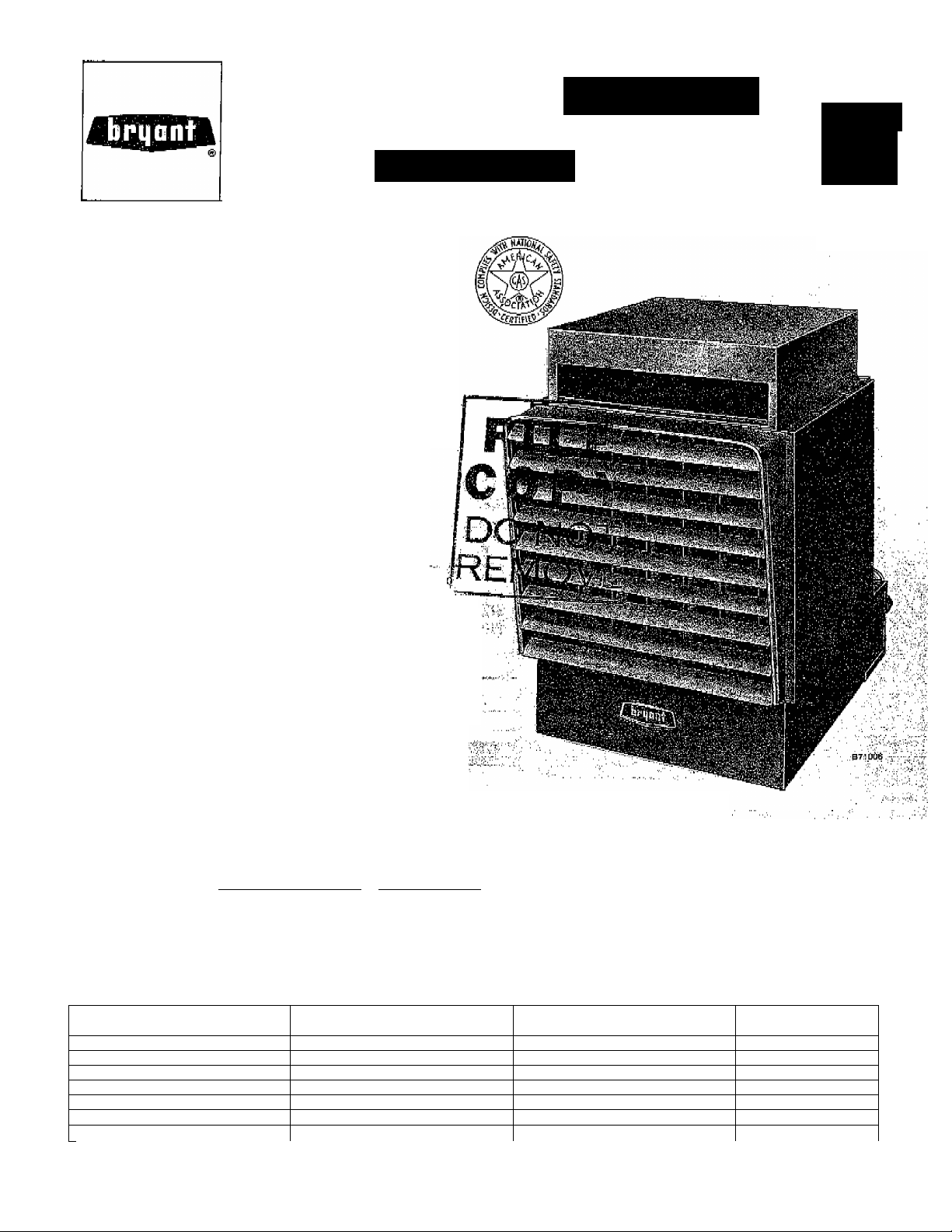
UNIT HEATERS
iiistructiòris
342S
: Series A
■Sizes 30
thru 400
Cancels; 39342D1
Before proceeding to install Models 342 and 342S Unit
Heaters, refer to Bryant form Ho, 39003D1 “Froeaduree for
Gas Appliances” (packaged with the equipment) for in
formation concerning combustion, venting, piping, and
other standard installation practices. The current edition of
the American National Standard “Installation of Gas Ap
pliances and Gas piping”, Z21.30, takes precedence over all
other reference publications pertinent to this -installation
instruction. Both models arc shipped factory-assembled,
Installation comprises the following;
* I. Inspection
* IL Location and Suspension
* III, piping '
lY, .
*** V. Venting
VL Startup'arid Adjustment
VII, Service 0;and„
=<To perform; .these -sepi^iops for installation steps-), jrefer t.
the ■;apprOpriath;''settiQhs^ Pr^atit' farm No.' 3&003D1
(packaged '■ With'ixfhis^ ^ .;.■■■ ■, ■ ^ '■ ■■ -
.' SPECIAL airplane aMANQAR AND : ; 1
. (5ARAGE APPLICATION PRECAUTIONS •
NOTE.:
cr aft ; Hangars, ” ahd^^HjFr'A ■; :NpT,;i':8g 2 ' Standard. .for
Gar ages; ” - . ''""uO.., .I.; 7 '■'.'li,'Ui'' 'A ■ '[,■ A ■', 1.,
1, A clearance of 10 feeti.;tb.Th^;'battom;;.o
'ifHe;:to,p,;h'f.J/a^'/wing-nr'Vfus^ /hr,:,¡aircraft likely^-tp'fee;''.'o
7 ■ .''hoiisedah:,;,'-the' .h angar 'must ;be' ■ in aint'ained " >.■ ;'i■■ ,i X 'i
■2. A'^mmimumyclearanqe':''.oi/$;%et';::^^^^ .the
bottom" ,'o.f ^thd '.'healtei:' ■ih./'hthef. .isepf ion^ .'pio^the ■.■;aircritft,
hangar, such '¿S' ofhe'es' ''an'd '¿hops' Vliich ■'''bb'fh muni cate .with areas used for servicing or storage, must be
maintained.
A-The heater;imn-Si .also be gg'lQcated. th;at it is.protected.'._____
from damage'by aircraft or other objects such as cranes 5, A service clearance of 18 inches at the rear and 12 ihor movable scaffoldings. In addition, it must be located ches from any obstruction at the bottom of the heatdr
"to be accessible for servicing and adjustment. must be maintained, " '
..........
Figure 1
4, A clearance of 6 inches from combustible maiterial
must be maintained from the top and the sidep of thd
...........
heater. ■;.'/:
39342D.PT3
11/1V4
i ' 7 ; COMPONENT ; •.
.Bryant Auto Pilot ...'..e ,
■Bryant'Gas 'Valve:!'■. ;■., ,'. ■ „"
Gas Pressure .Begulator"! /
. Transformer.: '.„..X;-...
,d0D%'5hutpff..j,'.;'j.:>.,-:
/7
■v.-.'. Therrlno.co(jple FMot
Pilot.Belay„:or Pilo,t3tat„ .
""’All ithree bphonB,'.'.ay&ilable',.-on- 342 '8438 .■a're..-availablB .'with '1).3 .propane and 'D5 natural '.gaa only. ^ ■/■.■■'■'i,
■H=A'-643;Bryàn!f Gas ,’Valv.e wjthÙntsBral gae pressure rsgulatpr .is used ;on -IÌ4.'Hiid D5 ibf sizes 30 thru IBO; A-641 Gas Valve wimoUt regulator
Used on-D2 for all 'sizes. -A-64l with separate gas ‘pressute Tegulator 'is'used on D4 and D5 for sises 175 'thru 40G. ■ ■ '
..:.7 "''7...'. .02.7,.'^
. .■ ir-!:'' ,7" ".' ;
'■ ... ...,..„7;T2.::. ix;: ; ■,:
.........
.............,,/■,
. . .,7'7:..'X'.7.: ... .. ,
.............. v
■
..........
TABLE l-^GDNTROL OPTIONS^
'PROPANE ;qA.s„,, .;■ ;
.7. .!7;'.7'7
........
, ,r,;.
.....
:'X
......
...
'¡..xx-',,.;. .'7. '■■
7.'v;,...
...........
■ ,":'7. ■ ■ -7 ,7
NATURAL
■' ,'X' " ' " ■'
" X'.^
■X
04 '
natural i
D5
.'. "X ■ "'.„T
■ . X ■ .
' X ■ . :
: 'X .
■ ,X ■' ..'7:
■X". ^ ',■;.'
Page 2
S E P / 0 9 / 2 0 0 8 / T U E 0 3 : 3 2
UTC TECH PUB
F A X N o , 3 1 7 2 4 0 5 6 6 2
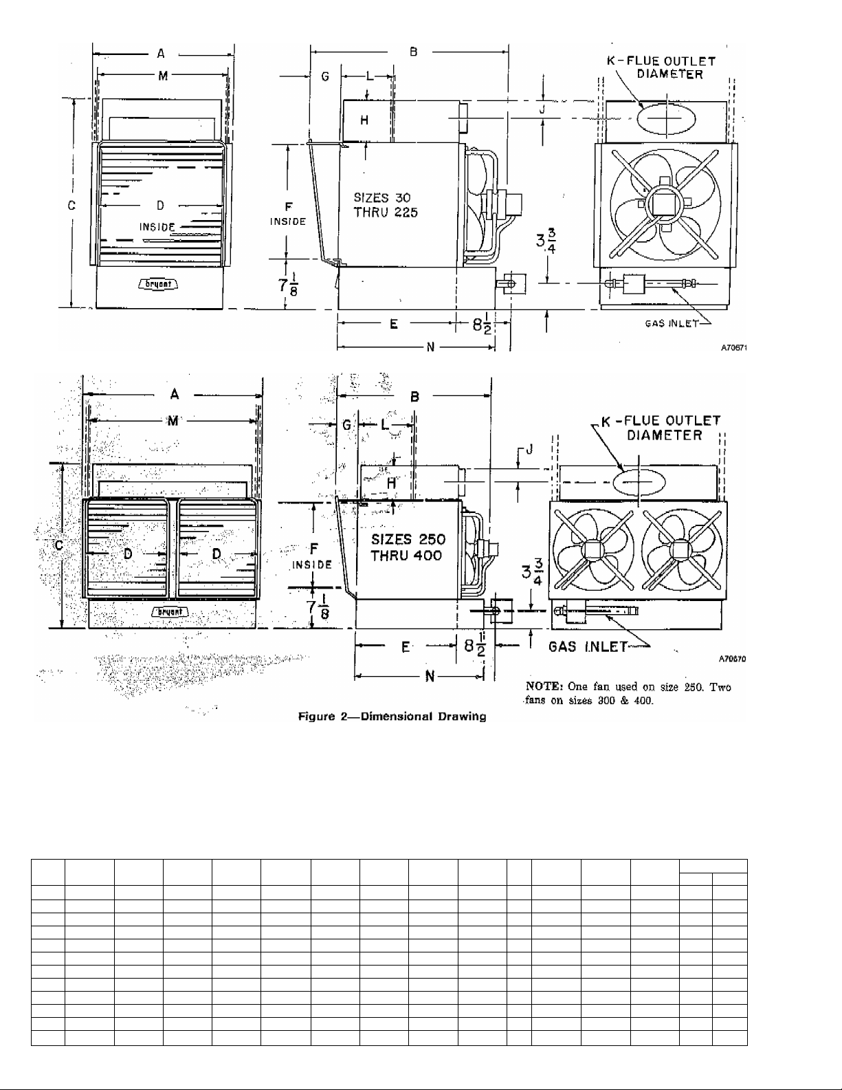
-T-A0U-E-|l=DlMENSl0NS-|N-|NeHES-
.. ,A, 0
3Q 11-.1/2 ■■
50 16-3/4 25-7/8
75 15-5/8 31-1/16... 30-1/0 ■
100 18»5/8 31-1/16 30-1/8 '
125 21-5/8 31-1/16., 31-5/8 ■■
150 24-5/8 31-1/16 31-5/8 '
175 21-5/8 37-1/4 34-5/8 20-3/16
200 24-5/8 ■ 37-1/4 ■ 34-5/8 ■ 23-3/16 23-7/0 21-W16
'225 27-5/8 37-1/4 34-6/8 26-3/16 '23-7/0 21-9/1.6
250 33-5/8 37-1/4 34-5/8 14-3/16 23-7/8 21-9/16
300
39-5/8 36-1/2 36-5/8 17-^3/16 23-7/8 ' 21-9/16
400 51-5/8 38 38 23-3/16
C
23-5/8 '
23-5/a 15-5/16 15 12-1/16 3-3/4 4-5/16; 2-1/8 4
D ■" -
10-1/1B . 15 ■ ■ ■ 12-1/16 ■ ■3-3/4 4-5/16 , 1:-,7/B 3
■14-3/16 1S-7/B 18-S/16 4-1/2 4-5/16 2-1/8
“17-3716 16-7/8 ■, 18-a/ie' 4-1/2 ’ 4-15/16 ■ 2-1/8 5
WsM'
23-3/16.-, 18-7/0 ■ i8-g/i6 4-1/2 5-13/16 2-7/8 7
1B-7/8' lB-¥/l6 ■4-1-/2 5-13/16: 2-11/16
23-7/8 21-9/16 4-15/16 5-13/16“
23-7/8
■ -
21-9/16 5-7/16
4-15/16
4-15/16 ■
4-15/16
4-15/16
-2-
' ' '■ J K
'2-7/8
5-13/16 , 2-7/0 0
5-13/16" '2-7/0 8 14-1/4 26-1/8 ' 30.31/32 1/2 .
5-13/16 T-T/a 8 Fr4-i/4 32-1/8 30-31/32 3/4 ■
7-13/16
9-5/16 TsTs 10 14-1/4 50-1/8 30-31/32 3/4
Tt70
...
10-1/8
'10-170““
5 12-1/8 14-1/8 25-31/82.
12-1/8 ■ ■17-1/8 25-31/32 1/2
6 ■12-1/8 20-1/8 , 25.31/32.'
12-1/8 23-1/8
7 14-1/4 20-1/8
14-1/4'
9 14-1/4 38-i/8 30-31/32 3/4 sTT'
___
10
15-1/4
23-1/8 , 30-31/32 1/2 1/2
M,
___N___
22-3/32
22^3/32
25-31/32 ;
30-31/3^
JiBi PXPRi
1/2 1/2
1/2
1/2
1/2
1/2
1/2
Inlet
1/2
1/2
1/2
1/2
1/2
■1/2
■1/2
3/4
3/4
Page 3

S E P / 0 9 / 2 0 0 8 / T U E 0 3 : 3 3
UTC TECH PUB
F A X N o , 3 1 7 2 4 0 5 6 6 2
TABLE III—RATINGS AND SPECIFICATIONS—MODEL 342
Equivalent
Sq Ft of
"’Ratings Btuh
Slzo
Input
30 30,OGO 24,000 100 Ô0 36Û 5S5 16 13 1500 i/iM
50 50, Odd 40,boo 1Й7 60 600 5Ô5 30 28 25 22 iSOO 1/40
76 75,000 60,000 250 70 900 615 36 33 30 28 1500 1/30
100 100,000
125 125,000
150
150,000 .120,000
175
175,0(i0 140,000 5?3
200
200,000 160,000 667
225
225,000 180,000 750 60
250
250,000 200,000 833 60 3000
300 300,000 240,000 1000 60 3600 900 75 73 70 68 65 63 60 58 55 53 50 1050 (2) 1/10 378
400 400,000 320,000 1334 60 480Ô 1000 90 88 85 83 80 78 75 73 70 68 65 1025 (2) j/5 560
^The above ratings are approved for altitudes to. 2000 ft. For elevations above 2000 ft, reduce ratings 4% for each 1000 ft above sea level.
=i=’i=Effective throw aa shown is the horizontal distance in feet that the heated airstream travels from the outlet of the unit heater with louvers
positioned for maximum throw with air reaching the floor, Spread or width of the air pattern is approximately 20% of the'maximum throw.
For additional spread, use vertical louvers, Above data are test results,
Output
50,000
100,000
Steam
Radiation
Temp
333 60 1200 675 45 43 40
417 60 1500 720 55 53 50 ' " 48 ■45 43 40 38 1050 1/10
500 60 1800 750 60 58 55 53 50 48 45 43 40 1050 1/10
Total
Air
Delivery
Rise
’‘F
60 21Ú0 850 65
60 2400 865 70
2700 860
CFM
Velocity
ft/mln
B50 05
Effective Throw Mounting Haight
Distance from Floor to Top of Hoator
8'
10' 12' 14'
38
63 60 58
60 65 63
70
68 65 63
63 60 58 55 53 50 43 45 1025
til
Fan
16' 18' 20' 22' 24' 2B' 28'
35 33 30 1050 1/15
55 53 50 48 45 , 1050
60 58 55 53 50 1050 1/5
60 58
55 53 50
FIFM
1050
Nominal
Motar
HP
1/5
1/5
1/5
Approx
Shipping
Weight
65 "
84
117
139
164
^ 180
212
235
258
317
Specific Location and Suspension Precautions
For general location and suspension information, refer to
Section II of Bryant form No, 33008Dl. b addition, the
following precautions should bs observed when selecting a
; mounting site,
1. Direct heated airstream toward area having greatest
heat loss.
2. For multiple installations, locate heaters so that each
will warm a specific area. Arrange so that the overall
air pattern results in a continuous circular flow of
warm air throughout the space,
3. Do not locate the heater in areas where combustion air
is limited,
4. If located in spaces equipped with exhaust fans,
provide sufficient makeup air.
5. Two l/2"inch pipe tappings are provided in the top
casing for use in suspending the heater. Use pipe
unions to join the unit heater to the ceiling hangar,
6. Do not lift the heater by the motor mount, manifold, or
louvers. Use a rope sling whenever this is possible.
IV. WIRING.
Make all electrical connections in accordance with the
National Electric Code and any_locaI codes .that may apply.
The unit must be grounded electrically in accordance with
the National Electric Code and local codes governing such
installations. A permanent and uninterrupted or unbroken
,.,ground,.is.es3enti al-to-minimi®ing.peEso naLin,j m,y_iLan-eiec=_
trical fault should occur.
If aluminum conductors are to be used, the wire size selec
ted must have a Current capacity not less than that of the
copper wire specified and must not create a voltage drop be
tween the service panel and the unit in excess of 2% of the
unit rated voltage. As a minimum, aluminum wire must be
treated to prevent oxidation.
With electric power turned off, recheck all electrical con
nections (both factory and field) for tightness. Be sure to
check power supply connections, especially if aluminum
conductors are used.
The unit heater is completely wired at the factory and is
ready for connections to a 116/60/1 power source. See
wiring diagram.
The heat anticipator on the thermostat should be set at 0.8
amps.
VI. STARTUP AND ADJUSTMENT
NOTE; Remove burner hold-down shipping bracket.
1. Start unit using procedure outlined on lighting instruc™
tion plate attached to heater.
2, Adjust pilot flame. Adjusting screw under screw cap on
pilot valve is used for this purpose,
For D4 controls, flame should be long enough for good
impingement on metal element of Bryant automatic
pilot. For D5 and D2 controls, flame should surround
thermocouple element of pilot and extend downward
to include 3/S to 1/2 inch of thermocouple. Flame
should never come in contact with any part of thermo
couple lead wire.
To adjust pilot flame on units equipped with Model AG43 valve, adjustment screw is located in pilot outlet
portion of valve body. Remove capscrew, make
..... .nsoe.gsai'y. .adjustment, and replace capscrew,...
...................
"^3-r“6heck"input. "Input-s'hduld"be checked'-at metev'to-rH'S'ka"“
sure that it corresponds with input shown on rating
plate attached to unit. See Bryant form No, 39003D1
for method.
4. Final Checkout. Move thermostat setting above and
below room temperature several times, pausing be-
—^tween..,each^-“on—-and—off-’-c-yclfc...to-njake-8ut.e-.that-
main burners ignite properly.
Attach low-voltage test light to electrical leads of
gaa valve. With thermostat set above room tem
perature, close manual pilot valve. If light goes out
when pilot cools, pilot is functioning properly. Test
light should go out within 45 seconds after pilot gas
supply is turned off.
Check Operation of temperature limit control. Do this
by allowing burners to operate while fan is not running
to see that limit switch opens.
— 3 —
Page 4

S E P / 0 9 / 2 0 0 8 / T D E 0 3 : 3 3 P M
UTC TECH PUB
P A X N o , 3 1 7 2 4 0 5 6 6 2
Check all connections in gas piping for leaks. Use soap-
and-water solution.
VIL SERVICE AND MAINTENANCE
1. Pilot Orifice - is located in bottom fitting of pilot and is
K readily accessible for inspection and cleaning.
3. Main Burner Orifices - Orifice is readily unscrewed
from manifold after burner is removed,
3. Removing Main Burners - Lift rear of burner and push
it away from manifold enough to disengage orifice spud
from mixer shield. Then pull down and out of heater.
End of burner away from manifold seats in slotted
burner support. It is necessary to lift burner out of this
slot before attempting to push burner back. See Figure
12.
NOTE: Disconnect the pilot tubing and wires to remove the
burner that holds the pilot. However, it is not necessary to
remove the pilot itself from the burner.
SIZES 30 THRU 150 UNIT HEATER WIRING DIAGRAMS
4. Cleaning - Heat exchanger tubes should be inspected
at regular intervals and cleaned when necessary.
a. Shut off gas and electricity. Heater should be cool.
b. Loosen two knurled-head screws to release rear
access door. Door will hang down freely.
c. Disconnect pilot tube and wireg.
d. Remove main burners and pilot.
e. Use stiff brush to scrub heat exchanger tubes.
Remove all loose scale and any soot that may have
collected.
f. Replace burners and pilot. Reconnect pilot tube
and wires.
g. Unit is now ready for relighting.
5. Oiling - Oil fan motor (s) yearly, or more often, with
enough drops of SAE No. 20 nondetergent oil to
overflow oil cup; or every 2 years, or more often, with
Anderol L-465* obtainable in tubes from your dealer.
(Bryant P/N 7O291D01). See FTB143.
*Lehigh Chemical Company
Figure 3^With 733 Pilot ihstaííed
Transformer 6B Pilot with Auto.
1A
Pan Relay—N.O, Ignition Coil
SG
ЗА Fan Motor
3A1 Fan Motor
Fan Motor
3A2
3C Fan Motor
Automatic Gas Valve
5A
0A Pilot Switch—No.O. If wires are replaced, use 18 AWG
(None on Propane) 150“
:: : 4—УУ1Ш FIIQÍ installed
LEGEND
7K Temp Limit Control—
SPOT—N.C.
7P Pressure Switch^—
SPST—N.O.
11A Resistor
C., 3/64-inch thick insulation.
— 4 -
Page 5

S E P / 0 9 / 2 0 0 8 / T U E 0 3 : 3 3 P M
UTC TECH PUB
SIZES 175 THRU 250 UNIT HEATER WIRING DIAGRAMS
F A X N o , 3 1 7 2 4 0 5 6 6 2
Figure 5—With 733 Pilot Installed
SIZE 300 UNIT HEATER WIRING DIAGRAMS
Figure 6—With 732 Pilot Installed
1A Tran3fùi‘rYier
2G Fan Relay—N,0.
3A. Fan Motor
Fan Motor
3A2
Fan Motor
3C
Automatic Gas Valve
5A
Pilot Switch—N.O.
6A
(None on Propane)
LEGEND
^ 5 -
6B Pilot with Auto.
Ignition Coil
7K Temp Limit Control—
SPOT—N,C,
Pressure Switch —
7P
S PST—N.O,
IIA Resistor
If wires are replaced, use 18 AWG
C„ 3/64-inch thick insulation.
150^
Page 6

S E P / 0 9 / 2 0 0 8 / T U E 0 3 : 3 4
Figure 9—With 733 Pilot Installed Figure 10—With 732 Pilot Installed
UTC TECH PUB
SIZE 400 UNIT HEATER WIRING DIAGRAMS
LEGEND
1A Transformer
2G Fan Relay—^N.0,
3C1 Fan Motor
F$n Motor SPST^N.;0,
3CS
5A Automatic Gas Valve
Pilot Switch—N.O.
6A
{Nons on Propane)
6B Pilot with Auto.,
Ignition Coil
7K
7P
11A Resistor
1S0°
F A X N o , 3 1 7 2 4 0 5 6 6 2
Tamp Limit Control—
SPOT—N.C.
Pressure Switch—
If wires are replaced, use 19 AWG
C,, 3/64-inch thick insulation.
6-
 Loading...