

Bryant 340MAV J Series Service And Maintenance Procedures Manual
service and
340MAV
maintenance procedures
4–WAY MULTIPOISE
FIXED-CAPACITY DIRECT-VENT
CONDENSING GAS FURNACE
A93040
NOTE: Read the entire instruction manual before starting the
installation.
This symbol → indicates a change since the last issue.
WARNING: ELECTRICAL SHOCK, FIRE,
OR EXPLOSION HAZARD
Failure to follow safety warnings exactly could result in
dangerous operation, serious injury, death, or property
damage.
Improper servicing could result in dangerous operation,
serious injury, death, or property damage.
- Before servicing, disconnect all electrical power to
furnace.
- When servicing controls, label all wires prior to disconnecting. Reconnect wires correctly.
- Verify proper operation after servicing.
WARNING: ELECTRICAL SHOCK, FIRE OR
EXPLOSION HAZARD
Failure to follow this warning could result in possible
damage to this equipment, serious personal injury, or
death.
The ability to properly perform maintenance on this
equipment requires certain expertise, mechanical skills,
tools, and equipment. If you do not possess these, do not
attempt to perform any maintenance on this equipment
other than those procedures recommended in the User’s
Manual.
Series J
Cancels: SP05-61 SP05-66
8-04
WARNING: FIRE OR EXPLOSION HAZARD
Failure to follow this warning could cause corrosion of
heat exchanger, fire, personal injury, or death.
Never store anything on, near, or in contact with the
furnace, such as:
1. Spray or aerosol cans, rags, brooms, dust mops,
vacuum cleaners, or other cleaning tools.
2. Soap powders, bleaches, waxes or other cleaning
compounds, plastic or plastic containers, gasoline,
kerosene, cigarette lighter fluid, dry cleaning fluids, or
other volatile fluids.
3. Paint thinners and other painting compounds, paper
bags, or other paper products.
TABLE OF CONTENTS
SAFETY CONSIDERATIONS.....................................................1
GENERAL......................................................................................2
ELECTROSTATIC DISCHARGE (ESD) PRECAUTIONS........2
CARE AND MAINTENANCE.....................................................3
Cleaning and/or Replacing Air Filter.......................................3
Blower Motor and Wheel Maintenance...................................4
Cleaning Burners ......................................................................4
Cleaning Heat Exchangers........................................................5
Primary Heat Exchanger........................................................5
Secondary Heat Exchanger....................................................6
Flushing Collector Box and Drainage System ........................6
Servicing Hot Surface Igniter...................................................8
Electrical Controls and Wiring.................................................8
Checking Heat Tape Operation (If Applicable) ......................9
Winterizing................................................................................9
WIRING DIAGRAM.....................................................................9
TROUBLESHOOTING ...............................................................10
Status Codes............................................................................10
Component Test......................................................................11
SAFETY CONSIDERATIONS
Recognize safety information. This is the safety-alert symbol
When you see this symbol on the furnace and in instructions or
manuals, be alert to the potential for personal injury.
Understand the signal words DANGER, WARNING, CAUTION,
and NOTE. These words are used with the safety-alert symbol.
DANGER identifies the most serious hazards which will result in
severe personal injury or death. WARNING signifies hazards
which could result in personal injury or death. CAUTION is used
to identify unsafe practices which may result in minor personal
injury or product and property damage. NOTE is used to highlight
suggestions which will result in enhanced installation, reliability,
or operation.
Installing and servicing heating equipmentcan be hazardous due to
gas and electrical components. Only trained and qualified
service agency personnel should install, repair, or service
.
—1—
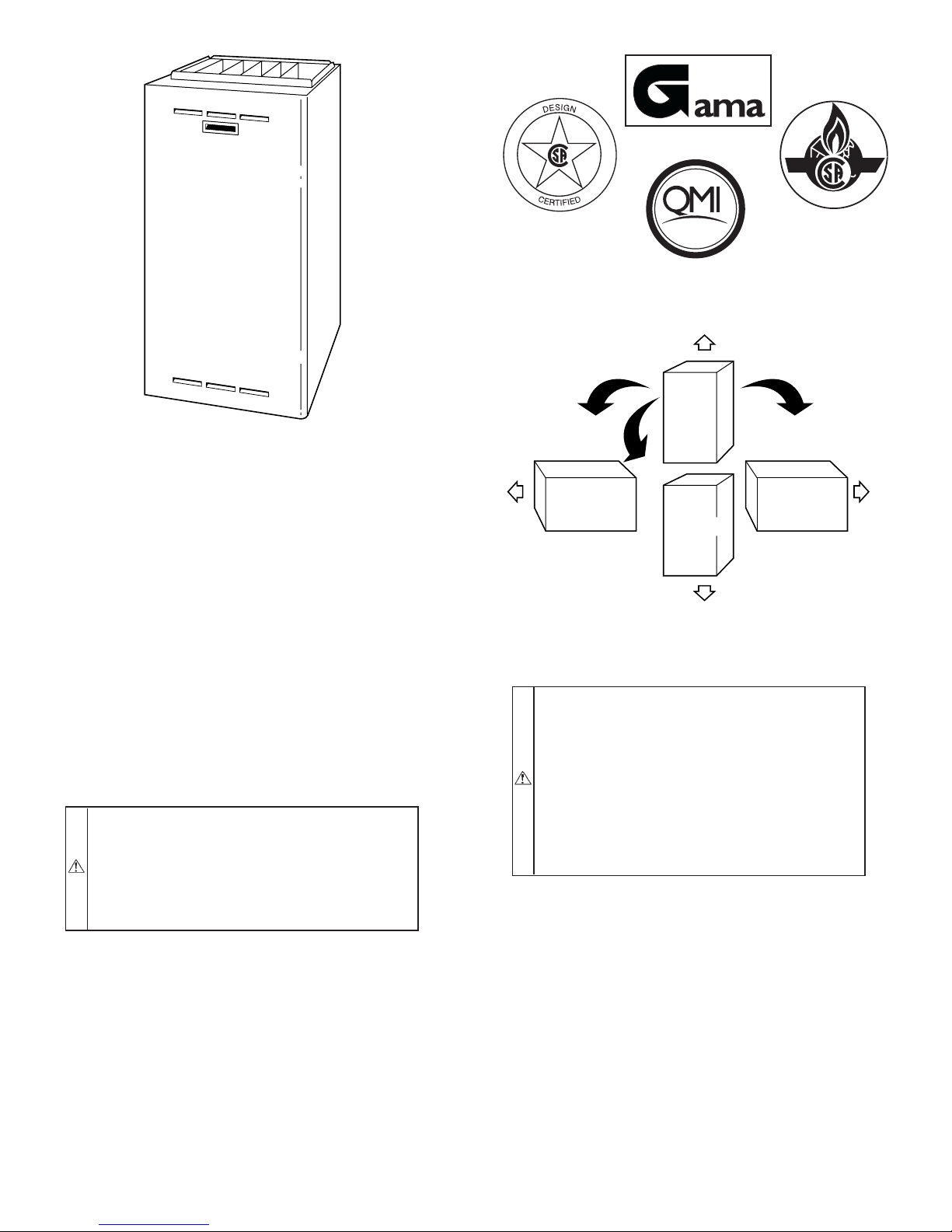
Fig. 1—Multipoise Furnace in Upflow Orientation
heating equipment. Untrained personnel can perform basic
maintenance functions described in User’s Information
Manual such as cleaning and replacing air filters. All other
operations must be performed by trained and qualified service
agency personnel. When working on heating equipment, observe
precautions in the literature, on tags, and on labels attached to or
shipped with the unit and other safety precautions that may apply.
Follow all safety codes including the National Fuel Gas Code
(NFGC) NFPA 54-2002/ANSI Z223.1-2002 in the USA; National
Standard of Canada, Natural Gas and Propane Installation Code
CSA B149.1-00 (NSCNGPIC) in Canada; and the Installation
Standards, Warm Air Heating and Air Conditioning Systems
(NFPA 90B) ANSI/NFPA 90B. Wear safety glasses and work
gloves. Have a fire extinguisher available during start-up and
adjustment procedures and service calls.
→
CAUTION: ELECTRICAL SHOCK AND UNIT
DAMAGE HAZARD
Failure to follow this caution may result in minor
personal injury or damage to furnace.
Label all wires prior to disconnection when servicing
controls. Wiring errors can cause improper and dangerous
operation.
GENERAL
These instructions are written as if the furnace is installed in an
upflow application. An upflow furnace application is where the
blower is located below the combustion and controls section of the
furnace, and conditioned air is discharged upward. Since this
furnace can be installed in any of the 4 positions shown in Fig. 2,
you may need to revise your orientation to component location
accordingly.
A98187
EFFICIENCY
RATING
CERTIFIED
ISO 9001:2000
REGISTERED
AIRFLOW
UPFLOW
HORIZONTAL
RIGHT
AIRFLOW
HORIZONTAL
LEFT
DOWNFLOW
AIRFLOW
Fig. 2—Multipoise Orientations
ELECTROSTATIC DISCHARGE (ESD) PRECAUTIONS
→
CAUTION: UNIT DAMAGE HAZARD
Failure to follow this caution may damage furnace
components.
Electrostatic discharge can affect electronic components.
Take precautions during furnace installation and servicing to protect the furnace electronic control. Precautions
will prevent electrostatic discharges from personnel and
hand tools which are held during the procedure. These
precautions will help to avoid exposing the control to
electrostatic discharge by putting the furnace, the control,
and the person at the same electrostatic potential.
1. Disconnect all power to the furnace. DO NOT TOUCH
THE CONTROL OR ANY WIRE CONNECTED TO THE
CONTROL PRIOR TO DISCHARGING YOUR BODY’S
ELECTROSTATIC CHARGE TO GROUND.
2. Firmly touch a clean, unpainted, metal surface of the
furnace chassis which is close to the control. Tools held in
a person’s hand during grounding will be satisfactorily
discharged.
3. After touching the chassis, you may proceed to service the
control or connecting wires as long as you do nothing that
recharges your body with staticelectricity (for example; DO
NOT move or shuffle your feet, DO NOT touch ungrounded objects, etc.).
4. If you touch ungrounded objects (recharge your body with
static electricity), firmly touch furnace again before touching control or wires.
CERTIFIED
AIRFLOW
A93041
—2—
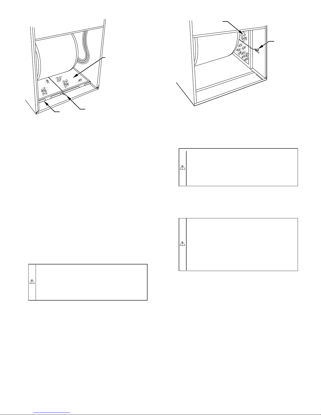
WASHABLE
FILTER
WASHABLE
FILTER
FILTER
RETAINER
FILTER
SUPPORT
Fig. 3—Bottom Filter Arrangement
FILTER
RETAINER
A93046
5. Use this procedure for installed and uninstalled (ungrounded) furnaces.
6. Before removing a new control from its container, discharge your body’s electrostatic charge to ground to protect
the control from damage. If the control is to be installed in
a furnace, follow items 1 through 5 before bringing the
control or yourself into contact with the furnace. Put all
used AND new controls into containers before touching
ungrounded objects.
7. An ESD service kit (available from commercial sources)
may also be used to prevent ESD damage.
CARE AND MAINTENANCE
For continuing high performance and to minimize possible furnace
failure, it is essential that maintenance be performed annually on
this equipment. Consult your local dealer about proper maintenance and maintenance contract availability.
WARNING: ELECTRICAL SHOCK HAZARD
Failure to follow this warning could result in personal
injury or death.
Turn off the gas and electrical supplies to the unit before
performing any maintenance or service. Follow the operating instructions on the label attached to the furnace.
The minimum maintenance that should be performed on this
equipment is as follows:
1. Check and clean or replace air filter each month as needed.
2. Check blower motor and wheel for cleanliness annually.
3. Check electrical connections for tightness and controls for
proper operation each heating season. Service as necessary.
4. Check for proper condensate drainage. Clean as necessary.
5. Check for blockages in combustion-air and vent pipes
annually.
6. Check burners for cleanliness annually.
Fig. 4—Filter Installed for Side Inlet
A93045
CAUTION: CUT HAZARD
Failure to follow this caution may result in personal
injury.
Be careful of sharp metal edges, etc. Use care and wear
protective clothing safety glasses, and gloves when removing parts.
I. CLEANING AND/OR REPLACING AIR FILTER
The air filter arrangement may vary depending on the application
or orientation.
WARNING: FIRE, CARBON MONOXIDE AND
POISONING HAZARD
Failure to follow this warning could result in a fire,
personal injury, or death.
Never operate unit without a filter or with the blower
access panel removed. Operating a unit without a filter or
with the blower accessdoor removed could cause damage
to the furnace blower motor. Dust and lint on internal
parts of furnace can cause a loss of efficiency
NOTE: If the filterhas cross-mesh binding, the binding must face
the blower. If the filter has an air direction arrow, the arrow must
point toward the blower.
To clean or replace the filters, proceed as follows:
1. Turn off electrical supply to furnace.
2. Remove main furnace door and blower access panel.
3. Release filter retainer wire. (See Fig. 3 or 4.)
4. Slide filter out of furnace.
5. Furnaces are equipped with permanent, washable filter(s).
Clean filter by spraying cold tap water through filter in
opposite direction of airflow.
6. Rinse filter and let dry. Oiling or coating of filter is not
recommended.
7. Slide filter into furnace.
8. Recapture filter retainer wire.
9. Replace blower access panel and main furnace door.
10. Turn on electrical supply to furnace.
—3—
II. BLOWER MOTOR AND WHEEL MAINTENANCE
To ensure long life, economy, and high efficiency, clean accumulated dirt and grease from blower wheel and motor annually.
The inducer and blower motors are pre-lubricated and require no
additional lubrication. These motors can be identified by the
absence of oil ports on each end of the motor.
The following items should be performed by a qualified service
technician.
Clean blower motor and wheel as follows:
1. Turn off electrical supply to furnace.
2. Remove main furnace door and blower access panel.
3. Disconnect blower motor wires from furnace control board.
Field thermostat connections may need to be disconnected
depending on their length and routing.
4. Remove control box mounting screws, and position control
box, transformer, and door switch assembly to right side of
furnace casing.
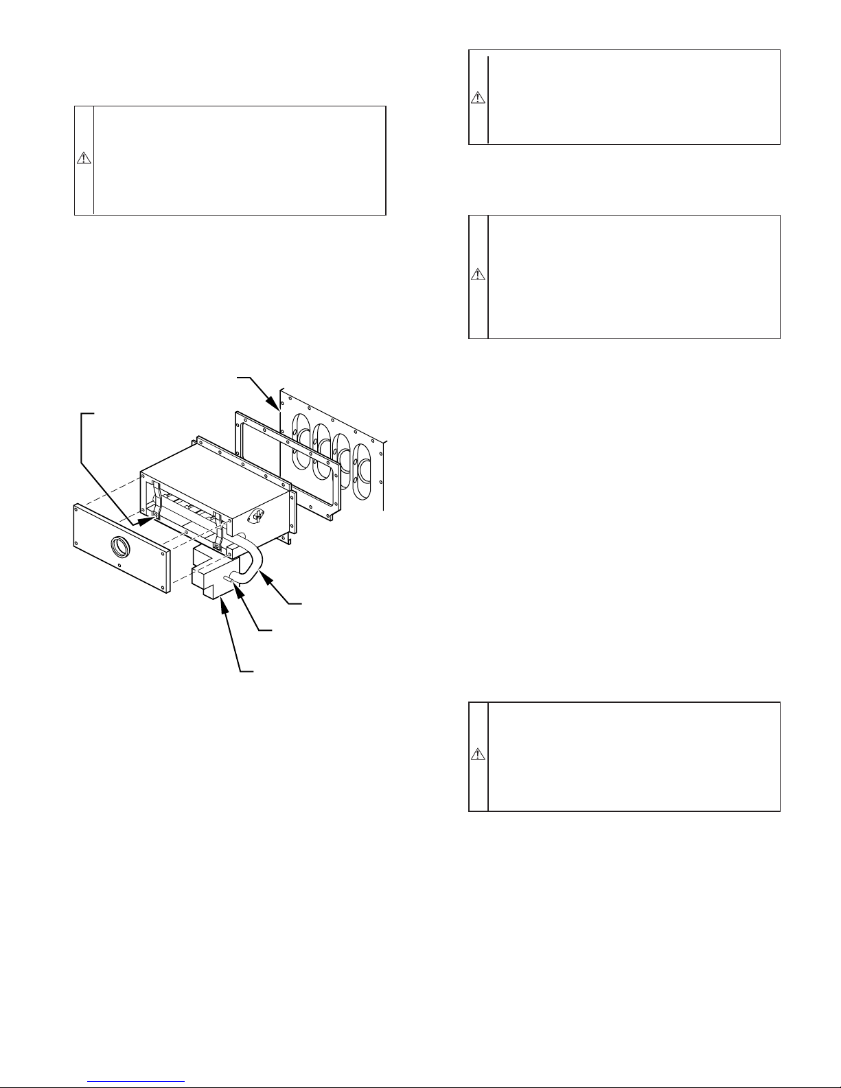
5. If condensate trap is located in left- or right-hand side of
furnace casing, proceed to item 6, otherwise remove trap
and tubing as described below. (See top left of Fig. 8.)
a. Disconnect field drain connection from condensate trap.
b. Disconnect drain and relief port tubes from condensate
trap.
c. Remove condensate trap from blower shelf.
6. Remove screws securing blower assembly to blower shelf
and slide blower assembly out of furnace.
7. Clean blower wheel and motor by using a vacuum with soft
brush attachment. Be careful not to disturb balance weights
(clips) on blower wheel vanes. Do not bend wheel or blades
as balance will be affected.
8. If greasy residue is present on blower wheel, remove wheel
from the blower housing and wash it with an appropriate
degreaser. To remove wheel:
a. Mark blower wheel location on shaft before disassembly
to ensure proper reassembly.
b. Loosen setscrew holding blower wheel on motor shaft.
NOTE: Mark blower mounting arms and blower housing so each
arm is positioned at the same hole location during reassembly.
c. Mark blower wheel orientation and cutoff plate location
to ensure proper reassembly.
d. Remove screws securing cutoff plate and remove cutoff
plate from housing.
e. Remove bolts holding motor mounts to blower housing
and slide motor and mounts out of housing. Disconnect
capacitor and ground wire attached to blower housing
before removing motor. Motor mounts need not be
removed from motor.
f. Remove blower wheel from housing.
→
CAUTION: UNIT DAMAGE HAZARD
Failure to follow this caution may result in noise or
furnace component failure.
The blower wheel should not be dropped or bent as
balance will be affected.
g. Clean wheel per instructions on degreaser cleaner. Do
not get degreaser cleaner in motor.
9. Reassemble motor and blower wheel by reversing items 8b
through 8f. Ensure wheel is positioned for proper rotation.
Be sure to reattach ground wire. Tighten setscrew to 140 to
160 in.-lb torque.
10. Reinstall blower assembly in furnace.
11. Reinstall control box, transformer, and door switch assembly on blower shelf.
12. Reinstall condensate trap and tubing if previously removed.
a. Reinstall condensate trap in hole in blower shelf.
b. Connect condensate trap drain tubes. See Fig. 8or tubing
diagram on main furnace door for proper tube location.
NOTE: Ensure tubes are not kinked or pinched, as this will affect
operation.
(1.) Connect 1 tube (blue or blue and white striped)
from collector box.
(2.) Connect 1 tube (violet or unmarked) from inducer
housing.
(3.) Connect 1 tube (relief port, green or pink) from
collector box.
c. Connect field drain to condensate trap.
13. Reconnect wires.
Refer to furnace wiring diagram, and connect thermostat leads if
previously disconnected. (See Fig. 16.)
NOTE: Refer to Table 1 for motor speed lead reconnection if
leads were not identified before disconnection.
CAUTION: UNIT DAMAGE HAZARD
Failure to adjust the heating speed may shorten heat
exchanger life.
Heating speed selection MUST be adjusted to provide
proper temperature rise as specified on the rating plate.
COLOR SPEED
Black High Cool
Yellow (When Present) Medium High Spare
Blue Medium Low Heat
Red Low Spare
White Common Com
FACTORY
ATTACHED TO
WARNING: ELECTRICAL SHOCK HAZARD
Failure to follow this warning could result in personal
injury or death.
Blower access door switch opens 115-v power to furnace
control. No component operation canoccur. Caution must
be taken when manually closing this switch for service
purposes.
14. Turn on electrical supply. Manually close blower access
door switch. Use a piece of tape to hold switch closed.
Check for proper rotation and speed changes by performing
a component self-test as shown at the bottom of SERVICE
label. (See Fig. 17.)
15. If furnace is operating properly, remove tape to release
blower access door switch, replace blower access door, and
replace main furnace door.
III. CLEANING BURNERS
The following items should be performed by a qualified service
technician. If the burners develop an accumulation of light dirt or
dust, they may be cleaned by using the following procedure:
1. Turn off gas and electrical supplies to furnace.
2. Remove main furnace door.
—4—
3. Remove burner box cover.
4. Using backup wrench, disconnect gas supply pipe from
furnace gas control valve.
→
CAUTION: ELECTRICAL SHOCK AND UNIT
DAMAGE HAZARD
Failure to follow this caution may result in minor
personal injury or damage to furnace.
Label all wires prior to disconnection when servicing
controls. Wiring errors can cause improper and dangerous
operation.
5. Remove wires from gas valve. Note location for reassembly.
6. Remove burner box pressure tube from gas valve regulator
fitting.
7. Remove screws that secure manifold to burner box. (See
Fig. 5.)
NOTE: Do not remove burner box from cell panel.
CELL
PANEL
MANIFOLD
MOUNTING
SCREW
MANIFOLD
GAS VALVE
REGULATOR
FITTING
GAS VALVE
Fig. 5—Burner Box Assembly
8. Remove manifold, orifices, and gas valve as one assembly.
9. Remove screws attaching burner assembly in burner box.
10. Remove burner assembly from burner box.
NOTE: All burners are attached to burner bracket and can be
removed as 1 assembly.
11. Clean burners with soft brush and vacuum.
12. Reinstall manifold, orifice, and gas valve assembly in
burner box. Ensure manifold seal grommet is installed
properly and burners fit over orifices.
13. Reconnect wires to gas valve. Refer to furnace wiring
diagram for proper wire location.
14. Reinstall burner box pressure tube to gas valve regulator
fitting.
15. Reinstall gas supply pipe to furnace gas control valve using
backup wrench on gas valve to prevent rotation and
improper orientation.
NOTE: Use propane gas resistant pipe dope to prevent gas leaks.
DO NOT use Teflon tape.
A96304
WARNING: FIRE, EXPLOSION, UNIT DAMAGE
HAZARD
Failure to follow this warning could result in property
damage, personal injury, or death.
Gas valve switch MUST be facing forward or tilted
upward.
16. Replace burner box cover.
17. Turn on gas and electrical supplies to furnace.
WARNING: FIRE OR EXPLOSION HAZARD
Failure to follow the safety warnings exactly could result
in serious injury, death, or property damage.
Never test for gas leaks with an open flame. Use a
commercially available soap solution made specifically
for the detection of leaks to check all connections. A fire
or explosion may result causing property damage, personal injury, or loss of life.
18. Check for gas leaks.
19. Replace main furnace door.
IV. CLEANING HEAT EXCHANGERS
The following items should be performed by a qualified service
technician.
A. Primary Heat Exchangers
If the heat exchangers get an accumulation of light dirt or dust on
the inside, they may be cleaned by the following procedure:
NOTE: If the heat exchangers get a heavy accumulation of soot
and carbon, both the primary and secondary heat exchangers
should be replaced rather than trying to clean them thoroughly due
to their intricate design. A build-up of soot and carbon indicates
that a problem exists which needs to be corrected, such as
improper adjustment of manifold pressure, insufficient or poor
quality combustion air, improper vent termination, incorrect size
or damaged manifold orifice(s), improper gas, or a restricted heat
exchanger (primary or secondary). Action must be taken to correct
the problem.
1. Turn off gas and electrical supplies to furnace.
2. Remove main furnace door.
→
CAUTION: ELECTRICAL SHOCK AND UNIT
DAMAGE HAZARD
Failure to follow this caution may result in minor
personal injury or damage to furnace.
Label all wires prior to disconnection when servicing
controls. Wiring errors can cause improper and dangerous
operation.
3. Disconnect wires or connectors to flame rollout switch, gas
valve, igniter, and flame sensor.
4. Disconnect combustion-air intake pipe from intake housing.
5. Remove the pressure switch tube from intake housing.
6. Remove screws attaching intake housing to burner box, and
rotate intake housing away from burner box for removal.
7. Using backup wrench, disconnect gas supply pipe from gas
valve.
8. Disconnect pressure tubing from gas valve.
9. Remove 2 screws attaching top filler panel and rotate
upwards to gain access to screws attaching burner box to
cell panel.
—5—
 Loading...