

Page 1
4-WAY MULTIPOISE
FIXED-CAPACITY
CONDENSING GAS FURNACE
combustion. The extracted heat lowers the temperature of the
combustion products to a point (typically below 115°F) that any
of the approved types of pipe can also be used for venting
combustion products outside the structure. The combustion-air
and vent pipes can terminate through a side wall or through the
roof when using 1 of our approved vent termination kits.
Flow-Through Secondary Heat Exchangers —Each cell is
laminated with our patented Everlastic
greater resistance to corrosion. This breakthrough in heating
technology helps extend the life of the furnace for years of
dependable performance. The heat exchanger is positioned in
the furnace to extract additional heat from the combustion
products regardless of furnace orientation.
Perfect Light™ Igniter —Bryant’s unique SiN igniter is not only
physically robust but it is also electrically robust. It is capable of
running at line voltage and does not require complex voltage
regulators as do other brands. This unique feature further
enhances the reliability of 340AAV gas furnace and continues
Bryant’s tradition of technology leadership and innovation in
providing a reliable and durable product.
340AAV
Sizes 040 thru 140
TM
polypropylene for
A05086
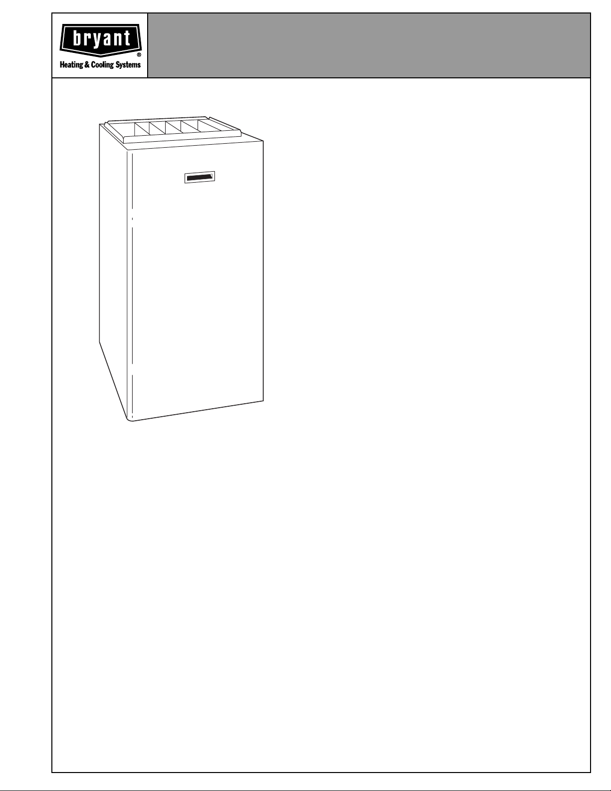
The model 340AAV Multipoise Condensing Furnace is specifically designed to meet the needs of the new construction
market. This high-efficiency furnace utilizes a unique 4-way
multipoise design and compact size to fit where other furnaces will not. The model 340AAV can be installed in any of 4
positions including horizontally in attics or crawlspaces, freeing space formerly used as a utility or furnace room. Except
for the 140 size, all sizes of the model 340AAV can be
installed in a manufactured (mobile) home when the optional
kit is used. With the exception of the 180 size, all sizes can be
installed with 2-pipe or 1-pipe venting. The 140 size can be
insalled only as a 2-pipe system. Sidewall or through-the-roof
venting options and the use of PVC pipe eliminate the need
for dedicated chimneys or chaseways to facilitate furnace
venting. Time-saving installation features yield a very cost
effective way to provide new home buyers with a high-efficiency and high-quality home comfort system.
FEATURES
3-Pass Primary Heat Exchangers —This design accelerates
heat transfer and extracts heat that conventional heat exchangers waste up the flue. The primary heat exchanger is made of
aluminized steel for corrosion resistance.
Combustion Air and Ventilation —The 340AAV advanced
design allows Schedule 40PVC, PVC-DWV, SDR-21 PVC,
SDR-26 PVC (not approved in Canada), ABS-DWV, or ABSF628 Schedule 40 pipe to bring outdoor air into the furnace for
Warranty —Limited Lifetime Warranty on the heat exchangers
for the lifetime of original owner in single family residence; 20
years in other residential and commercial applications. 5 year
Limited Warranty on entire unit.
Control Center —The printed-circuit board and all internal wir-
ing are factory installed. Convenient terminals permit quickconnection of a thermostat and air conditioning control circuits.
Connections for a humidifier and air cleaner are also provided.
4-Way Multipoise Design —Allows a model 340AAV to be
installed in an upflow, downflow, or horizontal orientation.
The model 340AAV is available in 12 heat/airflow combinations,
and when combined with the 4-way design, allows for 48 different
applications. Factory configured for upflow application, this furnace
can easily be made ready for downflow or horizontal installations.
Direct or Non-direct Venting —The 340AAV can be installed
as a 1 pipe/Non-Direct vent or 2 pipe/Direct vent furnace
except the 140 size which can be installed as 2-pipe only. This
provides added flexibility to meet diverse installation needs.
Insulated Casing —Foil-faced insulation in the heat exchanger
section cuts heat loss. The casing also has the required openings for left- or right-side connection of gas, electric, drain, and
vent connections.
Certifications —The 340AAV units are CSA (A.G.A./C.G.A.)
design certified for use with natural and propane gases, as well
as GAMA efficiency rating certified. The furnace is factoryshipped for use with natural gas. A CSA (A.G.A./C.G.A.) listed
gas conversion kit is required to convert furnace for use with
propane gas. The model 340AAV meets California Air Quality
Management District emission requirements. Except for the
140 size unit, all 340AAV models can be installed in a manufactured (mobile) home when the optional kit is used, and in
elevations up to 10,000 ft (140 size unit limitation of 7,000 ft).
Quality Registration —The 340AAV is engineered and manu-
factured under an ISO 9001 registered quality system.
Catalog No. PDS 340A.40.1
Page 2
"
8
⁄
"
16
"
16
⁄
13
⁄
5
"
8
⁄
5
7
39
1"
"
"
16
⁄
16
⁄
7
11
"
16
⁄
5
19"
"
22
4
⁄
1
"
16
⁄
26
15
"
2
⁄
26
1
OUTLET
2-IN. COMBUSTION-
AIR CONN
1
⁄2-IN. DIA
GAS CONN
7
⁄8-IN. DIA
POWER CONN
1
⁄2-IN. DIA
THERMOSTAT ENTRY
28
"
16
⁄
9
TYP
1
(DOWNFLOW &
OR ALTERNATE
TRAP LOCATION
"
16
/
13
A
D
"
16
/
13
OUTLET
AIRFLOW
HORIZONTAL RIGHT)
CONDENSATE DRAIN
-IN. DIA GAS CONN
2
⁄
1
"
4
⁄
1
TYP
33
"
8
⁄
5
TYP
32
"
16
⁄
13
30
2-IN. VENT CONN
"
2
⁄
30
11
"
16
⁄
11
22
SIDE INLET
1
" TYP
4
⁄
22
"
16
⁄
3
24
BOTTOM INLET
"
4
⁄
1
18
HANGING
(UPFLOW)
CONDENSAT E
DRAIN LOCATION
FOR HORIZONTAL
DIMPLE LOCATORS
"
16
/
11
-in. rectangle.
-in. rectangle.
/ 2
/ 4
1
1
x 19
x 23
x 12-in. rectangle.
/ 2
/ 2
1
1
/ 2
1
INLET
11
E
"
16
/
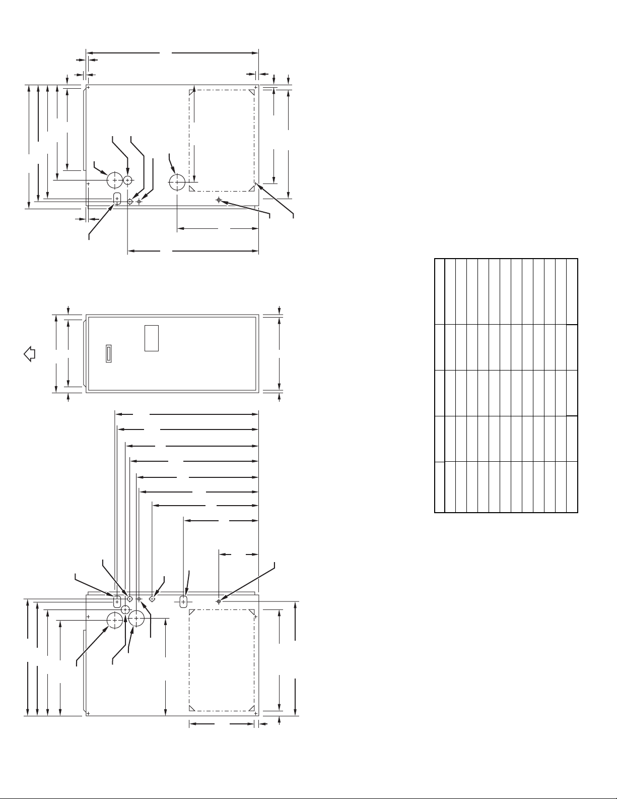
DIMENSIONS (In.)
"
16
⁄
TYP
29
"
8
⁄
5
27
"
16
⁄
9
TYP
"
27
2
⁄
1
24
"
16
⁄
5
17
see flex duct manufacturerís recommendations for equivalent diameters.
a.For 800 CFM–16-in. round or 14
2. Minimum return-air opening at furnace:
b. For 1200 CFM–20-in. round or 14
c. For 1600 CFM–22-in. round or 14
d. For airflow requirements above 1800 CFM, see Air Delivery table in Product Data
literature for specific use of single side inlets. The use of both side inlets, a
combination of 1 side and the bottom, or the bottom only will ensure adequate
return air openings for airflow requirements above 1800 CFM at 0.5” W.C. ESP.
024040 17-1/2 15-7/8 16 165
036040 17-1/2 15-7/8 16 166
024060 17-1/2 15-7/8 16 172
UNIT SIZE A D E SHIP. WEIGHT (Lb)
036060 17-1/2 15-7/8 16 174
048060 17-1/2 15-7/8 16 174
036080 17-1/2 15-7/8 16 188
048080 17-1/2 15-7/8 16 194
060080 21 19-3/8 19-1/2 206
048100 21 19-3/8 19-1/2 219
060100 21 19-3/8 19-1/2 221
060120 24-1/2 22-7/8 23 250
060140 24-1/2 22-7/8 23 250
A05070
"
16
(ALTERNATE
UPFLOW)
⁄
7
9
SIDE INLET
"
2
⁄
1
TYP
14
TYP
"
4
⁄
1
1
CONDENSAT E
DRAIN LOCATION
" TYP
4
⁄
1
23
SIDE INLET
1"
(UPFLOW)
" TYP
16
⁄
15
NOTES: 1. Minimum return-air openings at furnace, based on metal duct. If flex duct is used,
26
⁄8-IN. DIA
7
POWER CONN
CONDENSAT E
DRAIN TRAP
CONDENSATE DRAIN
TRAP LOCATION
(DOWNFLOW &
HORIZONTAL LEFT)
"
16
⁄
"
15
4
⁄
1
"
26
2
⁄
1
26
"
16
⁄
24
5
22
⁄2-IN. DIA
2-IN. COMBUSTION-
AIR CONN
1
GAS CONN
2-IN. VENT CONN
⁄8-IN. DIA
7
ACCESSORY
ENTRY
"
16
⁄
11
22
⁄2-IN. DIA THERMOSTAT
1
LOCATION
POWER ENTRY
—2—
Page 3
CLEARANCE TO COMBUSTIBLES
This forced air furnace is equipped for use with natural gas at altitudes 0 - 10,000 ft (0 - 3,050m), except 140 si ze Furnaces are only approved for altitudes 0 - 7,000 ft. (0 - 2,135m).
INSTALLATION
An accessory kit, supplied by the manuf acturer, shall be used to convert to propane gas use or may be required for some natural gas appli cations.
This furnace i s for i ndoor inst allati on in a buildi ng constr ucted on si te. Thi s furnace may be i nstalled in a manuf actured (mob ile) home when stated on rating plate and using factory
authorized kit.
This furnace may be ins talled on combustibl e flooring i n alcove or closet at minimum clearanc e from combust ible material .
This appliance requires a special venting system. Refer t o the install ation i nstructions for parts l ist and method of instal lation. This f urnace is for use wi th schedul e-40 PVC, PVC-DWV,
CPVC, or ABS-DWV pipe, and must not be vented in common wit h other gas-fired appli ances. Construction through which vent/ air i ntake pipes may be installed is maximum 24 inches
(600 mm), minimum 3/4 inches (19 mm) thickness (including roofing materials).
Cette fournaise à air pulsé est équipée pour utilisation avec gaz naturel et altitudes comprises entre 0 - 3,050m
(0-10,000 pi), excepté queles fournaises de 140 taille sont pour altitudes comprises entre 0 - 2,135m (0 - 7,000 pi).
Utiliser une trousse de conversion, f ournie par le fabr icant, pour pas ser au gaz propane ou pour ce rtaines installat ions au gaz naturel.
Cette fournaise à air pulsé est pour installation à l´intérieur dans un bâti ment construit sur place. Cette fournaise à air pulsé peut êt re inst allée dans une maison préfabriquée
(maison mobile) si prescrit par la plaque signalétique et si l´on utilise une trousse specifiée par le fabricant.
Cette fournaise peut être installée sur un plancher combustible dans un enfoncement ou un placard en observant les dégagements minimums avec les matériaux combustibles.
Cet appareil nécessite un système d´évacuation spécial. La méthode d´installation et la liste des pièces nécessaires figurent dans les instructions d´installation.Cette fournaise doit
s´utiliser avec la tuyauterie des nomenclatures 40 PVC, PVC-DWV, CPVC, ou ABS-DWV et elle ne peut pas être ventilée conjointm ent avec d´autres appareils à gaz. Épaisseur de la
constr uction au travers de laque lle il est poss ible de fair e passer l es tuyaux d´aération (admi ssion/évacuat ion): 24 po (600 mm) maximum, 3/4 po (19 mm) mi ni mum (y compri s la toit ure).
For upflow and downflow applications, furnace must be installed level, or pitched within 1/2"
of level. For a horizontal application, the furnace must be pitched minimum 1/4" to
maximum of 1/2" forward for proper drainage. See Installation Manual for IMPORTANT unit
support details on horizontal applications.
Pour des applications de flux ascendant et descendant, la fournaise doit être installée de
niveau ou inclinée à pas plus de 1/2" du niveau. Pour une application horizontale, la
fournaise doit être inclinée entre minimum 1/4" et maximum 1/2" du niveau pour le drainage
approprié. En cas d'installation en position horizontale, consulter les renseignements
IMPORTANTS sur le support dans le manuel d'installation.
MINIMUM INCHES CLEARANCE TO COMBUSTIBLE CONSTRUCTION
ALL POSITIONS:
Minimum front clearance for service 30 inches (762mm).
*
†
†
140 size furnaces require 1 inch back clearance to combustible materi als.
R
DOWNFLOW POSITIONS:
For installation on combustible floors only when installed on special base No. KGASB0201ALL, Coil
†
Assembly, Part No. CD5 or CK5, or Coil Casing, Part No. KCAKC.
HORIZONTAL POSITIONS:
Line contact is permissi bl e only between lines formed by int ersections of top and t wo sides of furnace
jacket, and building joists, studs, or framing.
Clearance shown is for air inlet and air outlet ends.
§
120 and 140 size furnaces require 1 inch bottom clearance to combustible materials.
Ø
DÉGAGEMENT MINIMUM EN POUCES AVEC ÉLÉMENTS DE CONSTRUCTION COMBUSTIBLES
POUR TOUS LES POSITIONS:
Dégagement avant minimum de 762mm (30 po) pour l´entretien.
*
Pour les fournaises de 140 taille, 1 po (25mm) dégagement des matériaux combustibles est requis
†
†
au-arriere.
POUR LA POSITION COURANT DESCENDANT:
Pour l´instal lation sur le plancher combustible seulement quand on utilise la base spéciale, pièce
†
n° KGASB0201ALL, l´ensemble serpentin, pièce n° CD5 ou CK5, ou le carter de serpentin, pièce
n° KCAKC.
POUR LA POSITION HORIZONTALE:
Le contact n´est permis qúentre les lignes formées par les intersections du dessus et des deuxcôtés de la
chemise de la fournaise, et des solives, des montants ou de la charpente du bátiment.
La distance indiquée concerne l´extrémité du tuyau d´arrivée d´air et l´extrémité du tuyau de sortie d´air.
§
Pour les fournaises de 120 et 140 taille, 1 po (25mm) dégagement des matériaux combustibles est requis
Ø
au-dessous.
324999-201 REV. D (LIT TOP)
LEVEL (0")
TO
1/2" MAX
UPFLOW OR
DOWNFLOW
MIN 1/4"
TO
1/2" MAX
FRONT
This furnace is approved for UPFLOW, DOWNFLOW and
HORIZONTAL i nstall ations.
Cette fournaise est approuvée pour l´installation HORIZONTALE
et la ci rculati on d´air VERS LE HAUT et VERS LE BAS.
Clearance arrows
do not change with
furnace orientat ion.
†
†
0"
B
A
A
C
R
K
R
I
E
R
I
S
O
C
0"
§
Clearance in inches
Dégagement (po).
FRONT
1"
TOP/PLENUM
E
E
D
S
E
T
F
BOTTOM
0"
†
HORIZONTAL
Les fléches de dégagement
ne change pas avec
l´orientation de la
générateur d´air chaud.
I
DESSUS/ CHAMBRE D´AI
N
R
U
R
U
O
F
F
F
A
V
DESSOUS
Ø
S
O
E
C
C
E
A
S
I
A
N
T
N
O
T
R
N
A
V
A
S
E
L
È
N
R
T
O
N
T
A
N
T
3"
Vent clearance to
combustibles 0".
0 (po) Dégagement
d´évent avec combustibles.
D
R
§
0"
E
S
E
T
R
V
I
C
E
E
T
I
E
*
N
30
MIN
As an ENERGY STAR
SM
Partner, Bryant
Heating & Cooling Systems has
determined that this product meets the
ENERGY STAR guidelines for energy
efficiency.
ama
MEETS DOE RESIDENTIAL
CONSERVATION SERVICES
PROGRAM STANDARDS.
Before purchasing this appliance,
read important energy cost and
efficiency information available from
your retailer.
—3—
A02148
CERTIFIED
ISO 9001:2000
REGISTERED
®
REGISTERED QUALITY SYSTEM
These products are engineered and
manufactured under an ISO 9001
registered quality system.
Page 4
Controls—Thermostats and Zoning
Non-Programmable Thermostat Selection
TSTATBBNAC01-C
TSTATBBNHP01-C
TSTATBBN2S01-C
TSTATBBBAC01-B
TSTATBBPRH01-B**
* Model HP and 2S thermostat must be field converted to air conditioner operation.
**Thermidistat Control is versatile and can be configured for multiple use and staging, it must be configured for each specific application.
TSTATBBPAC01-B
TSTATBBPHP01-B*
TSTATBBP2S01-B*
TSTATBBSAC01
TSTATBBPDF01-B**
TSTATBBPRH01-B***
* Model HP and 2S thermostat must be field converted to air conditioner operation.
**Dual Fuel thermostat is used with furnace and heat pump application
***Thermidistat Control can be configured for multiple use and staging, it must be configured for each specific application.
For use with 1-spd. Air Conditioner - deg. F/C, Auto Changeover
For use with 1-spd. Air Conditioner - deg. F/C, Auto Changeover
For use with 2-spd. Air Conditioner - deg. F/C, Auto Changeover
For use with 1-spd. Air Conditioner - deg. F/C
For multi-use / stage configurations - deg. F/C, Auto Changeover/Temperature and Humidity Control
Programmable Thermostat Selection
For use with 1-spd. Air Conditioner - deg. F/C, Auto Changeover, 7-Day Programmable
For use with 1-spd. Air Conditioner - deg. F/C, Auto Changeover, 7-Day Programmable
For use with 2-spd. Air Conditioner - deg. F/C, Auto Changeover, 7-Day Programmable
For use with 1-spd. Air Conditioner - deg. F/C, 5-2 Day Programmable
For use with multi-stage applications - deg. F/C, Auto Changeover, 7-Day Programmable
For multi-use / stage configurations - deg. F/C, Auto Changeover, 7-Day Programmable/Temperature and Humidity Control
ZONEBB3Z(AC/HP)01
ZONEBB2KIT01-B
ZONEBB4KIT01-B
ZONEBB8KIT01-B
Zoning Control Selection
Zone Perfect Two-Zone kit
Zone Perfect Plus 2-Zone kit/Temperature and Humidity Control
Zone Perfect Plus 4-Zone kit/Temperature and Humidity Control
Zone Perfect Plus 8-Zone kit/Temperature and Humidity Control
—4—
Page 5
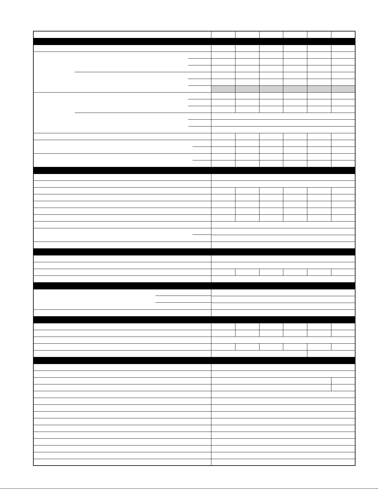
SPECIFICATIONS
UNIT SIZE 024040 036040 024060 036060 048060 036080
RATINGS AND PERFORMANCE
Input Btuh* 40,000 40,000 60,000 60,000 60,000 80,000
Output Capacity
BTUH* (ICS)
(Shaded capacities
are specified on rating plate)
AFUE%
Nonweatherized ICS
Certified Temperature Rise Range °F 30—60 15—45 45—75 30—60 20—50 40—70
Certified External Static Pressure Heating 0.10 0.10 0.12 0.12 0.12 0.15
Airflow CFM‡ Heating 850 1125 885 1065 1320 1190
ELECTRICAL
Unit Volts—Hertz—Phase 115—60—1
Operating Voltage Range Min—Max** 104—127
Maximum Unit Amps 10.0 14.1 10.2 14.8 14.6 14.3
Unit Ampacity†† 13.4 18.4 13.5 19.3 19.1 18.8
Minimum Wire Size 14 12 14 12 12 12
Maximum Wire Length (Ft)‡‡ 28 31 27 30 30 30
Maximum Fuse Size or Ckt Bkr Amps (Time-Delay Type Recommended) 20 15 20 20 20 20
Transformer (24v) 40va
External Control Heating 12va
Power Available Cooling 21va
Air Conditioning Blower Relay Standard
CONTROLS
Limit Control SPST
Heating Blower Control (Off Delay) Factory-Set at 135 Sec
Burners (Monoport) 445566
Gas Connection Size 1/2-in. NPT
GAS CONTROLS
Gas Valve (Redundant) Manufacturer White-Rodgers
Ignition Device Hot Surface
BLOWER DATA
Direct-Drive Motor HP (Permanent Split Capacitor) 1/2 3/4 1/2 3/4 3/4 3/4
Motor Full Load Amps 7.9 11.1 7.9 11.1 11.1 11.1
RPM (Nominal)—Speeds 1075—4
Blower Wheel Diameter x Width (In.) 11 x 8 11 x 10 11 x 8 11 x 10 11 x 10 11 x 10
Filter Size (In.)—Permanent Washable (1) 20 x 25 x 1 (2)16 x 25 x 1
FACTORY-AUTHORIZED AND LISTED, DEALER-INSTALLED OPTIONS
Gas Conversion Kit—Natural-to-Propane KGANP4001ALL
Gas Conversion Kit—Propane-to-Natural KGAPN3301ALL
Twinning Kit KGATW0601HSI
Manufactured (Mobile) Home Kit KGAMH0102KIT
Downflow Base*** KGASB0201ALL
Vent Termination Kit (Bracket Only for 2 Pipes) 2-in.—KGAVT0101BRA 3-in.—KGAVT0201BRA
Concentric Vent Termination Kit (Single Exit) 2-in.—KGAVT0501CVT 3-in.—KGAVT0601CVT
Condensate Freeze Protection Kit KGAHT0101CFP
Condensate Neutralizer Kit (Obtained Thru RCD) P908-0001
Side Filter Rack (Without Filter)—Upflow ONLY KGAFR0206ALL
Electronic/Mechanical Air Cleaner Model EACA, EZXCAB, or FILCAB
Humidifier Model HUM
Heat/Energy Recovery Ventilator Model HRV
UV Lights Model UVL
Door Gasket Kit KGBAC0110DGK
See notes on page 7.
Direct Vent (2-Pipe) Upflow
Downflow
Horizontal
Non-Direct Vent (1-Pipe) Upflow
Downflow
Horizontal
Direct Vent (2-Pipe) Upflow
Downflow
Horizontal
Non-Direct Vent (1-Pipe) Upflow
Downflow
Horizontal
Cooling 0.50 0.50 0.50 0.50 0.50 0.50
Cooling 895 1215 900 1200 1545 1245
Min Inlet Pressure (In. wc) 4.5 (Natural Gas)
Max Inlet Pressure (In. wc) 13.6 (Natural Gas)
—5—
37,000 37,000 56,000 56,000 56,000 74,000
37,000 37,000 56,000 56,000 56,000 74,000
37,000 37,000 56,000 56,000 56,000 74,000
37,000 37,000 56,000 56,000 56,000 74,000
37,000 37,000 56,000 56,000 56,000 74,000
37,000 37,000 56,000 56,000 56,000 74,000
92.3 92.3 92.3 92.3 92.3 92.3
91.2 91.2 91.2 91.2 91.2 91.2
92.1 92.1 92.1 92.1 92.1 92.1
92.1
91
91
N/A
N/A
Page 6

SPECIFICATIONS
UNIT SIZE 048080 060080 048100 060100 060120 060140
RATINGS AND PERFORMANCE
Input Btuh*
Output Capacity
BTUH* (ICS)
(Shaded capacities
are specified on rating plate)
AFUE%
Nonweatherized ICS
Certified Temperature Rise Range °F 30—60 15—45 45—75 30—60 20—50 40—70
Certified External Static Pressure Heating 0.10 0.10 0.12 0.12 0.12 0.15
Airflow CFM‡ Heating 850 1125 885 1065 1320 1190
ELECTRICAL
Unit Volts—Hertz—Phase 115—60—1
Operating Voltage Range Min—Max** 104—127
Maximum Unit Amps 6.1 7.3 6.1 7.1 9.5 7.6
Unit Ampacity†† 8.4 10.0 8.4 9.8 12.8 10.4
Minimum Wire Size 14 14 14 14 14 14
Maximum Wire Length (Ft)‡‡ 44 37 44 38 29 36
Maximum Fuse Size or Ckt Bkr Amps
(Time-Delay Type Recommended) 15 15 15 15 15 15
Transformer (24v) 40va
External Control Heating 12va
Power Available Cooling 21va
Air Conditioning Blower Relay Standard
CONTROLS
Limit Control SPST
Heating Blower Control (Off Delay) Factory-Set at 135 Sec
Burners (Monoport) 223334
Gas Connection Size 1/2-in. NPT
GAS CONTROLS
Gas Valve (Redundant) Manufacturer White-Rodgers
Ignition Device Hot Surface
BLOWER DATA
Direct-Drive Motor HP (Permanent Split Capacitor) 1/5 1/3 1/5 1/3 1/2 1/3
Motor Full Load Amps 4.9 5.8 4.9 5.8 7.9 5.8
RPM (Nominal)—Speeds 1075—3 1075—4 1075—3 1075—4
Blower Wheel Diameter x Width (In.) 10 x 6 10 x 7 10 x 6 10 x 7 11 x 8 10 x 7
Filter Size (In.)—Permanent Washable (1) 16 x 25 x 1
FACTORY-AUTHORIZED AND LISTED, DEALER-INSTALLED OPTIONS
Gas Conversion Kit—Natural-to-Propane KGANP4001ALL
Gas Conversion Kit—Propane-to-Natural KGAPN3301ALL
Twinning Kit N/A
Manufactured (Mobile) Home Kit KGAMH0101KIT
Downflow Base*** KGASB0201ALL
Vent Termination Kit (Bracket Only for 2 Pipes) 2-in.—KGAVT0101BRA 3-in.—KGAVT0201BRA
Concentric Vent Termination Kit (Single Exit) 2-in.—KGAVT0501CVT 3-in.—KGAVT0601CVT
Condensate Freeze Protection Kit KGAHT0101CFP
Condensate Neutralizer Kit (Obtained Thru RCD) P908-0001
Side Filter Rack (Without Filter)—Upflow ONLY KGAFR0206ALL
Electronic/Mechanical Air Cleaner Model EACB, EZXCAB, or FILCAB
Humidifier Model HUM
Heat/Energy Recovery Ventilator Model HRV
UV Lights Model UVL
Door Gasket Kit KGBAC0110DGK
Direct Vent (2-Pipe) Upflow
Downflow
Horizontal
Non-Direct Vent (1-Pipe) Upflow
Downflow
Horizontal
Direct Vent (2-Pipe) Upflow
Downflow
Horizontal
Non-Direct Vent (1-Pipe) Upflow
Downflow
Horizontal
Cooling 0.50 0.50 0.50 0.50 0.50 0.50
Cooling 895 1215 900 1200 1545 1245
Min Inlet Pressure (In. wc) 4.5 (Natural Gas)
Max Inlet Pressure (In. wc) 13.6 (Natural Gas)
See notes on page 7.
80,000 80,000 100,000 100,000 120,000 140,000
74,000 74,000 93,000 93,000 112,000 127,000
74,000 74,000 93,000 93,000 112,000 127,000
74,000 74,000 93,000 93,000 112,000 127,000
74,000 74,000 93,000 93,000 112,000 NA
74,000 74,000 93,000 93,000 112,000 NA
74,000 74,000 93,000 93,000 112,000 NA
92.3 92.3 92.3 92.3 92.3 92.3
91.2 91.2 91.2 91.2 91.2 91.2
92.1 92.1 92.1 92.1 92.1 92
92.1 NA
91 NA
91 NA
KGATW0601HSI
N/A
—6—
Page 7

* Gas input ratings are certified for elevations to 2000 ft. For elevations above 2000 ft, reduce ratings 2% for each 1000 ft above sea level. In Canada, derate the unit
5% from 2000 to 4500 ft above sea level.
† Capacity and AFUE in accordance with U.S. Government DOE test procedures.
‡ Airflow shown is for bottom only return-air supply. Air delivery above 1800 CFM may require that both sides, a combination of 1 side and bottom, or bottom only of the
furnace be used for return air, see Air Delivery table. Where 2 sets of data are listed, the first set is for bottom only return-air supply. The second set is for both sides,
or 1 side and bottom return-air supply. A filter is required for each return-air supply.
** Permissible voltage limits for proper furnace operation.
†† Unit ampacity = 125% of largest component’s full load amps plus 100% of all other potential operating components (EAC, humidifier, etc.).
‡‡ Length shown is measured 1 way along wire path between unit and service panel for maximum 2% voltage drop.
*** Required for installation on combustible floors when no coil box is used, or when any coil box other than a Bryant CD5, CK5, or KCAKC cased coil is used.
N/A—Not applicable
ICS—Isolated Combustion System
—7—
Page 8

COMBUSTION-AIR AND VENT PIPING Direct-Vent/2-Pipe (All Sizes) and
Non-Direct Vent/1-Pipe (Sizes 040 Through 120 Only) Applications
ALTITUDE (FT)
0 to 2000
ALTITUDE (FT)
2001 to 3000
ALTITUDE (FT)
3001 to 4000
See notesat end of table
UNIT SIZE
(BTUH)
40,000
60,000
80,000
100,000
120,000
140,000
UNIT SIZE
(BTUH)
40,000
60,000
80,000
100,000
120,000
140,000
UNIT SIZE
(BTUH)
40,000
60,000
80,000
100,000
120,000
140,000
MAXIMUM ALLOWABLE PIPE LENGTH (FT)
DIRECT VENT (2-PIPE) ONLY
TERMINATION
TYPE
2 Pipe or 2-in
Concentric
2 Pipe or 2-in
Concentric
2 Pipe or 2-in
Concentric
2 Pipe or 3-in
Concentric
2 Pipe or 3-in.
Concentric
2 Pipe or 3-in.
Concentric
DIRECT VENT (2-PIPE) ONLY
TERMINATION
TYPE
2 Pipe or 2-in
Concentric
2 Pipe or 2-in
Concentric
2 Pipe or 2-in
Concentric
2 Pipe or 3-in
Concentric
2 Pipe or 3-in.
Concentric
2 Pipe or 3-in.
Concentric
DIRECT VENT (2-PIPE) ONLY
TERMINATION
TYPE
2 Pipe or 2-in
Concentric
2 Pipe or 2-in
Concentric
2 Pipe or 2-in
Concentric
2 Pipe or 3-in
Concentric
2 Pipe or 3-in.
Concentric
4† no disk 4†nodisk4†nodisk 707070707070
2 Pipe or 3-in.
Concentric
PIPE DIA
(IN.)*
1 1 5 NANANANANA
1-1/2 1-1/2 70 70 65 60 60 55
2 2 70 70 70 70 70 70
1-1/2 1-1/2 20 15 10 5 NA NA
2 2 70 70 70 70 70 70
1-1/2 1-1/2 10 NA NA NA NA NA
22555035 30 3020
2-1/2 2-1/2 70 70 70 70 70 70
2 2 5 NANANANANA
2-1/2 2-1/2 40 30202010NA
3370 70 70 70 70 70
2-1/2 one disk 2-1/2 10 NA NA NA NA NA
3†NA454035 302520
3†nodisk 3† 707070707070
2-1/2 one disk NA 5 NA NA NA NA NA
3†onediskNA4035 30252015
3†nodiskNA60565248 44 40
4† no disk NA 707070707070
PIPE DIA
(IN.)*
1-1/2 1-1/2 67 62 57 52 52 47
2 2 70 70 70 70 70 70
1-1/2 1-1/2 17 12 7 NA NA NA
2 2 70 67 66 61 61 61
22494430252515
2-1/2 2-1/2 70 70 70 70 70 70
2-1/2 2-1/2 352616 16 6 NA
3370 70 70 70 66 61
3 NA 14 9 NA NA NA NA
NA 3†63 62 62 61 61 61
3†nodiskNA707063 56 50 43
4† no disk4†nodisk 707070707070
3† one diskNA2015105NANA
3†nodiskNA39 35 312723 19
4† no disk NA 707070707070
PIPE DIA
(IN)*
1-1/2 1-1/2 64 59 54 49 48 43
2 2 70 70 70 70 70 70
1-1/2 1-1/2 16 11 6 NA NA NA
2268 63 62 57 57 56
2 2 46 41 28 23 22 13
2-1/2 2-1/2 70 70 70 70 70 70
2-1/2 2-1/2 33 24 15 14 5 NA
3370 70 70 66 61 56
3†nodiskNA6558 51 44 38 31
NA 3†595958 57 57 56
3† one disk NA 11 6 NA NA NA NA
3†nodiskNA302622 18 14 10
4† no disk NA 707070707070
NON-DIRECT VENT
(1-PIPE) ONLY
PIPE DIA
(IN.)*
NON-DIRECT VENT
(1-PIPE) ONLY
PIPE DIA
(IN.)*
NON-DIRECT VENT
(1-PIPE) ONLY
PIPE DIA
(IN.)*
NUMBER OF 90° ELBOWS
1234 56
NUMBER OF 90° ELBOWS
1234 56
NUMBER OF 90° ELBOWS
1234 56
—8—
Page 9

COMBUSTION-AIR AND VENT PIPING Direct-Vent/2-Pipe (All Sizes) and
ALTITUDE (FT)
4001 to 5000‡
ALTITUDE (FT)
5001 to 6000‡
ALTITUDE (FT)
6001 to 7000‡
See notesat end of table
Non-Direct Vent/1-Pipe (Sizes 040 Through 120 Only) Applications
MAXIMUM ALLOWABLE PIPE LENGTH (FT) (CONTINUED)
UNIT SIZE
(BTUH)
40,000
60,000
80,000
100,000
120,000
140,000
UNIT SIZE
(BTUH)
40,000
60,000
80,000
100,000
120,000
140,000
UNIT SIZE
(BTUH)
40,000
60,000
80,000
100,000
120,000
140,000
DIRECT VENT (2-PIPE) ONLY
TERMINATION
TYPE
2 Pipe or 2-in
Concentric
2 Pipe or 2-in
Concentric
2 Pipe or 2-in
Concentric
2 Pipe or 3-in
Concentric
2 Pipe or 3-in.
Concentric
2 Pipe or 3-in.
Concentric
DIRECT VENT (2-PIPE) ONLY
TERMINATION
TYPE
2 Pipe or 2-in
Concentric
2 Pipe or 2-in
Concentric
2 Pipe or 2-in
Concentric
2 Pipe or 3-in
Concentric
2 Pipe or 3-in.
Concentric
2 Pipe or 3-in.
Concentric
DIRECT VENT (2-PIPE) ONLY
TERMINATION
TYPE
2 Pipe or 2-in
Concentric
2 Pipe or 2-in
Concentric
2 Pipe or 2-in
Concentric
2 Pipe or 3-in
Concentric
2 Pipe or 3-in.
Concentric
2 Pipe or 3-in.
Concentric
PIPE DIA
(IN.)*
1-1/2 1-1/2 60 55 50 45 44 39
2 2 70 70 70 70 70 70
1-1/2 1-1/2 15 10 5 NA NA NA
2 2 64 59 58 53 52 52
22443926 21 2011
2-1/2 2-1/2 70 70 70 70 70 70
2-1/2 2-1/2 312213 12 NA NA
3370 70 67 62 57 52
3†nodiskNA53 46 40 33 26 20
NA 3†56555453 52 52
4† no disk 4†nodisk 707070707070
3†nodiskNA211713 95NA
4† no disk NA 696459544944
PIPE DIA
(IN.)*
1-1/2 1-1/2 57 52 47 42 40 35
2 2 70 70 70 70 70 70
1-1/2 1-1/2 14 9 NA NA NA NA
2 2 60 55 54 49 48 47
22413623 18 17 8
2-1/2 2-1/2 70 70 70 70 70 70
2-1/2 2-1/2 29 21 12 11 NA NA
3370 67 62 57 52 47
3†nodiskNA423529 2215 9
NA 3†53 52 50 49 48 47
4† no disk4†nodisk 707070707070
3†nodiskNA128 NA NA NA NA
4† no diskNA4237 32272217
PIPE DIA
(IN)*
1-1/2 1-1/2 53 48 4
2 2 70 70 68 67 66 64
1-1/2 1-1/2 138NA NA NA NA
2 2 57 52 50 45 44 43
2238 33 21 16 15 6
2-1/2 2-1/2 70 70 68 67 66 64
2-1/2 2-1/2 27 19 10 9 NA NA
3368 63 58 53 48 43
3†nodiskNA312418 11 NA NA
NA 3†4948 47 45 44 43
4† no disk4†nodisk 707070706762
4† no diskNA17127NANANA
NON-DIRECT VENT
(1-PIPE) ONLY
PIPE DIA
(IN.)*
NON-DIRECT VENT
(1-PIPE) ONLY
PIPE DIA
(IN.)*
NON-DIRECT VENT
(1-PIPE) ONLY
PIPE DIA
(IN)*
NUMBER OF 90° ELBOWS
123456
NUMBER OF 90° ELBOWS
123456
NUMBER OF 90° ELBOWS
123456
33837 32
—9—
Page 10

COMBUSTION-AIR AND VENT PIPING Direct-Vent/2-Pipe (All Sizes) and
Non-Direct Vent/1-Pipe (Sizes 040 Through 120 Only) Applications
MAXIMUM ALLOWABLE PIPE LENGTH (FT) (CONTINUED)
ALTITUDE (FT)
7001 to 8000‡
ALTITUDE (FT)
8001 to 9000‡
ALTITUDE (FT)
9001 to 10,000‡
*Disk usage-Unless otherwise specified, use perforated disk assembly (factory-supplied in loosepartsbag). If one diskisstated, separate 2 halves of perforated disk
assembly and use shouldered diskhalf. When using shouldered diskhalf, install screen side toward inlet box.
†Wide radius elbow.
‡Vent sizing for Ca
NA-Not Allowed; pressure switch will not make.
NOTES:
1. Do not use pipe size greater thanthose specified in table or incomplete combustion, flame disturbance, or flame senselockoutmay occur.
2. Size both the combustion-air and vent pipe independently, then usethel
3.Assume two 45° elbows equal one 90° elbow. Wide radius elbowsare desirable and may berequired in some cases.
4. Elbowsand pipe sections within the furnace casing and at the vent termination should not be included in vent length or elbow count.
5. The minimum pipe length is 5ftforall applications.
6. Use 3-in. diameter vent termination kit for in
UNIT SIZE
(BTUH)
40,000
60,000
80,000
100,000
120,000
140,000 NA
UNIT SIZE
(BTUH)
40,000
60,000
80,000
100,000
120,000
140,000 NA
UNIT SIZE
(BTUH)
40,000
60,000
80,000
100,000
120,000
140,000 NA
nadianinstallations over 4500 ft (1370 m) above sea level are subject to acceptance bythelocal authorities having jurisdiction.
DIRECT VENT (2-PIPE) ONLY
TERMINATION
TYPE
2 Pipe or 2-in
Concentric
2 Pipe or 2-in
Concentric
2 Pipe or 2-in
Concentric
2 Pipe or 3-in
Concentric
2 Pipe or 3-in.
Concentric
DIRECT VENT (2-PIPE) ONLY
TERMINATION
TYPE
2 Pipe or 2-in
Concentric
2 Pipe or 2-in
Concentric
2 Pipe or 2-in
Concentric
2 Pipe or 3-in
Concentric
2 Pipe or 3-in.
Concentric
DIRECT VENT (2-PIPE) ONLY
TERMINATION
TYPE
2 Pipe or 2-in
Concentric
2 Pipe or 2-in
Concentric
2 Pipe or 2-in
Concentric
2 Pipe or 3-in
Concentric
2 Pipe or 3-in.
Concentric
stallations requiring 4-in diameter pipe.
PIPE DIA
(IN.)*
1-1/2 1-1/2 49 44 39 34 33 28
2 2 66 65 63 62 60 59
1-1/2 1-1/2 12 7 NA NA NA NA
2253 48 46 41 40 38
2236 31191412NA
2-1/2 2-1/2 66 65 63 62 60 59
2-1/2 2-1/2 25 17 8 7NANA
3363 58 53 48 4338
3†nodiskNA2013 7NANANA
NA 3†464443 41 40 38
4† no disk4†nodisk615651464136
PIPE DIA
(IN.)*
1-1/2 1-1/2 46 41 36 312924
2 2 62 60 58 56 55 53
1-1/2 1-1/2 11 6 NA NA NA NA
2 2 49 44 42 37 35 34
2233 28 17 12 10 NA
2-1/2 2-1/2 62 60 58 56 55 53
2-1/2 2-1/2 23 15 7 5 NA NA
3359 54 49 44 39 34
3†nodisk NA 10NANANANANA
NA 3†43 41 39 37 35 34
4† no disk4†nodisk 35 3025201510
PIPE DIA
(IN.)*
1-1/2 1-1/2 42 37 32272520
2 2 57 55 53 51 49 47
2 2 45 40 38 33 3129
223025 14 9 7 NA
2-1/2 2-1/2 57 55 53 51 49 47
2-1/2 2-1/2 21 13 5NANANA
3354 49 44 39 3429
NA 3† 39 37 35 33 3129
4† no disk 4†nodisk 10 5 NA NA NA NA
arger diameter for both pipes.
NON-DIRECT VENT
(1-PIPE) ONLY
PIPE DIA
(IN.)*
NON-DIRECT VENT
(1-PIPE) ONLY
PIPE DIA
(IN.)*
NON-DIRECT VENT
(1-PIPE) ONLY
PIPE DIA
(IN.)*
NUMBER OF 90° ELBOWS
123456
NUMBER OF 90° ELBOWS
123456
NUMBER OF 90° ELBOWS
123456
—10—
Page 11

(
MAXIMUM ALLOWABLE EXPOSED VENT PIPE LENGTH (FT) WITH AND WITHOUT INSULATION
IN WINTER DESIGN TEMPERATURE AMBIENT*
WINTER DESIGN
UNIT SIZE
TEMPERATURE
°F)
20 1-1/2 51 70
024040
036040
0 1-1/2 28 70
–20 1-1/2 16 70
024060
036060
048060
036080
048080
060080
20 2 65 70
0 2 35 70
–20 2 20 70
20 2-1/2 70 70
0 2-1/2 47 70
–20 2-1/2 28 70
20 3 70 70
048100
060100
0 3 50 70
–20 3 28 70
20 4 70 70
060120
0 4 48 70
–20 4 23 70
20 4 70 70
060140
0 4 57 70
–20 4 30 70
* Pipe length (ft) specified for maximum vent pipe lengths located in unconditioned spaces. Vent pipes located in unconditioned space cannot exceed the
total allowable pipe length as specified in Maximum Allowable Pipe Length table.
† Insulation thickness based on R value of 3.5 per in.
MAX PIPE
DIAMETER
(IN.)
WITHOUT
INSULATION
WITH 3/8-IN. OR
THICKER INSULATION†
BLOWER SHELF
CONDENSATE
TRAP (INSIDE)
ALTERNATE DRAIN
TUBE LOCATION
CONDENSATE TRAP
DRAIN TUBE LOCATION
UPFLOW APPLICATIONS
CONDENSATE TRAP
FURNACE
DOOR
FIELD
DRAIN
CONN
SIDE VIEW FRONT VIEW END VIEW FRONT VIEW
DOWNFLOW AND ALTERNATE
EXTERNAL UPFLOW APPLICATIONS
SLOT FOR SCREW
HORIZONTAL
APPLICATION
(OPTIONAL)
1
1
2
3
4
3
1
4
WIRE TIE
GUIDES
(WHEN USED)
FRONT VIEW SIDE VIEW
CONDENSATE
TRAP
1
26
4
7
FURNACE
1
7
8
8
2
SIDE
1
1
1
4
FURNACE
DOOR
7
4
8
2
1
⁄4 OD
COLLECTOR BOX TO
TRAP RELIEF PORT
1
⁄2 OD
INDUCER HOUSING
DRAIN CONNECTION
5
⁄8 OD
COLLECTOR BOX
DRAIN CONNECTION
SCREW HOLE FOR
UPFLOW OR DOWNFLOW APPLICATIONS
(OPTIONAL)
1
⁄2-IN. PVC OR CPVC
FIELD
DRAIN
CONN
4
26
HORIZONTAL
APPLICATIONS
3
5
4
1
4
4
3
FURNACE
SIDE
3
5
4
A93026
4
—11—
Page 12

ACCESSORIES
CONCENTRIC VENT FOR DIRECT VENT (2-PIPE) APPLICATION
(ALL MODEL SIZES)
B IN. DIA PVC
VENT/EXHAUST
F
E
21
SIDE FILTER RACK*
3
1
⁄8″
1 1⁄4″ (TYP)
1 1⁄4″
TABS
25 1⁄8″
⁄2″
2 3⁄8″
3
⁄4″
13/16
1
/2
1
B IN. DIA PVC
INTAKE/COMBUSTION AIR
C IN. DIA
D
A
DIMENSIONS (In.)
PART NO. A* B C D† E F
KGAVT0501CVT 33-3/8 2 3-1/2 16-5/8 6-1/4 5-3/4
KGAVT0601CVT 38-7/8 3 4-1/2 21-1/8 7-3/8 6-1/2
* Dimension A will change accordingly as dimension D is lengthened or shortened.
† Dimension D may be lengthened to 60 in. maximum. Dimension D may also be shortened by
cutting the pipes provided in the kit to 12 in. minimum.
NOTE: See furnace Installation Instructions when venting multiple
furnaces near each other.
LENGTH OF STRAIGHT
PIPE PORTION OF COMBUSTION
AIR INLET PIPE ASSEMBLY (IN.)
CASING WIDTH A
17-1/2
24-1/2
8-1/2 ± 1/2
10-1/2 ± 1/2
12 ± 1/2
17 1⁄8″
23 1⁄8″
OPENING
14 1⁄
2
OPENING
16
″
A80199
1
⁄8″
* Accepts one 16 x 25 x 1 in. filter.
Combination-Air Pipe for Non-Direct Vent (1-Pipe)
Application (Sizes 040 Through 120 Only)
FIELD-SUPPLIED
2-IN. DIAMETER
PVC 90° ELBOW
COMBUSTION-AIR DISC
(FACTORY-SUPPLIED IN
LOOSE PARTS BAG)
FIELD-SUPPLIED
2-IN. DIAMETER
PVC PIPE
A
A96211
A96211
ACCESSORY DOWNFLOW SUBBASE
A88207
4
3
2
1
A
LOCATING
TAB
LOCATING
TAB
B
D
FACTORY-SUPPLIED
1
2
3
4
FIELD-INSTALLED
INSULATION
Disassembled Assembled
FURNACE
CASING
WIDTH FURNACE IN DOWNFLOW APPLICATION
17-1/2
21
24-1/2
Furnace with or without Cased Coil
Assembly or Coil Box
Furnace with or without Cased Coil
Assembly or Coil Box
Furnace with or without Cased Coil
Assembly or Coil Box
* The plenum should be constructed 1/4 in. smaller in width and depth than the plenum dimensions shown above.
PLENUM OPENING* FLOOR OPENING HOLE NO.
15-1/8 19 16-3/4 20-3/8 3
18-5/8 19 20-1/4 20-3/8 2
22-1/8 19 23-3/4 20-3/8 1
—12—
1 1/
″ TYP
4
PLENUM
OPENING
C
FOR WIDTH
ADJUSTMENTABCD
Page 13

AIR DELIVERY—CFM (With Filter)*
UNIT SIZE
024040
036040
024060
036060
048060
036080
048080
060080
048100
060100
060120
060140
* A filter is required for each return-air supply.
• For horizontal and downflow applications, use “1 side or bottom” or “bottom only” as airflow reference.
RETURN-AIR
SUPPLY SPEED
1 side
or
bottom
1 side
or
bottom
1 side
or
bottom
1 side
or
bottom
1 side
or
bottom
1 side
or
bottom
1 side
or
bottom
1 side
or
bottom
both sides or
1 side and
bottom
1 side
or
bottom
1 side
or
bottom
both sides or
1 side and
bottom
bottom
only
both sides or
1 side and
bottom
1 side only
bottom
only
both sides or
1 side and
bottom
1 side only
Med-Low
Med-High
Med-Low
Med-Low
Med-High
Med-Low
Med-High
Med-Low
Med-High
Med-Low
Med-High
Med-Low
Med-High
Med-Low
Med-High
Med-High
Med-Low
Med-High
Med-Low
Med-High
Med-High
Med-Low
Med-High
Med-High
Med-High
Med-Low
Med-High
Med-High
High
Low
High
Low
High
Low
High
Low
High
Low
High
Low
High
Low
High
Low
High
High
Low
High
Low
High
High
Low
High
High
High
Low
High
High
0.1 0.2
1075
850
740
1470
1315
1125
930
1100
890
745
1430
1270
1070
915
1700
1500
1325
1205
1535
1395
1200
1040
1750
1495
1310
1135
2200
2100
1815
1560
2360
1965
1740
1500
1340
1195
2250
2020
1725
1490
2360
1960
2350
2100
1770
1545
2435
2040
2255
1985
2285
2020
1675
1460
2310
1975
2140
1930
1040
825
700
1415
1280
1110
925
1065
865
710
1375
1260
1055
895
1695
1465
1295
1170
1470
1350
1175
1020
1685
1455
1260
1105
2175
2025
1760
1555
2280
1925
1705
1470
1315
1175
2175
1950
1690
1480
2315
1940
2250
2015
1720
1520
2360
2000
2190
1930
2210
1970
1650
1445
2255
1945
2080
1850
EXTERNAL STATIC PRESSURE (In. wc)
0.3
995
780
650
1400
1235
1085
910
1005
810
670
1325
1215
1045
885
1640
1435
1265
1145
1405
1300
1125
990
1635
1405
1225
1075
2085
1945
1720
1515
2210
1870
1660
1445
1300
1165
2090
1900
1660
1460
2265
1930
2160
1955
1675
1465
2285
1950
2115
1890
2140
1920
1620
1430
2185
1900
2025
1800
0.4
945
740
620
1285
1180
1045
850
945
765
625
1275
1160
1015
865
1580
1385
1230
1110
1330
1225
1065
960
1575
1355
1170
1040
2025
1865
1670
1460
2130
1830
1615
1410
1270
1130
2020
1840
1630
1440
2200
1900
2070
1875
1620
1415
2220
1905
2045
1840
2065
1870
1590
1400
2120
1860
1945
1740
0.5
895
685
565
1215
1115
990
830
900
705
565
1200
1105
975
840
1545
1355
1190
1080
1245
1155
1030
910
1525
1305
1125
995
1925
1785
1620
1435
2035
1760
1570
1375
1235
1100
1930
1790
1575
1380
2130
1850
2000
1810
1575
1365
2130
1835
1965
1780
1990
1805
1560
1370
2045
1835
1875
1725
0.6
840
635
515
1120
1035
915
770
805
620
505
1135
1035
920
800
1450
1300
1150
1035
1160
1080
970
860
1445
1250
1095
995
1820
1700
1550
1390
1960
1710
1500
1330
1200
1070
1855
1710
1520
1340
2055
1800
1885
1710
1515
1325
2050
1790
1890
1720
1910
1730
1510
1320
1965
1775
1795
1660
0.7 0.8
760
560
455
995
930
830
705
730
540
425
1040
950
850
720
1380
1250
1105
990
1065
985
890
785
1380
1185
1040
910
1735
1620
1480
1340
1875
1670
1425
1280
1140
1030
1760
1640
1460
1295
1965
1740
1790
1650
1450
1265
1965
1725
1800
1645
1830
1660
1450
1275
1880
1720
1725
1580
670
480
385
890
825
740
635
610
475
360
935
850
750
650
1310
1185
1050
950
935
880
780
680
1310
1120
980
860
1635
1540
1405
1270
1790
1575
1355
1210
1095
975
1670
1545
1370
1230
1890
1660
1635
1540
1365
1185
1875
1650
1710
1560
1745
1590
1390
1230
1800
1640
1625
1495
—13—
Page 14

OUTDOOR UNIT
COMBUSTION
AIR INLET
(NON-DIRECT
1-PIPE APPLICATION)
COMBUSTION AIR PIPE
(DIRECT VENT/2-PIPE APPLICATION)
A/C COIL
ELECTRONIC
AIR CLEANER
VENT PIPE
HUMIDIFIER
GAS-FIRED
WATER HEATER
AIRFLOW
ELECTRONIC
AIR CLEANER
COMBUSTION AIR
INLET (NON-DIRECT
VENT/ 1-PIPE APPLICATION
HUMIDIFIER
FRONT OF
FURNACE
A05064
VENT
COMBUSTION
AIR (DIRECT VENT/
2 PIPE APPLICATION
OUTDOOR
UNIT
A/C COIL
FRONT OF
AIRFLOW
FURNACE
A05065
—14—
Page 15

COMBUSTION-AIR INLET
(NON-DIRECT VENT/1-PIPE APPLICATION)
ELECTRONIC
AIR CLEANER
FRONT OF FURNACE
AIRFLOW
VENT PIPE
FURNACE
CONDENSATE
DRAIN
REFRIGERATION
COMBUSTION–AIR PIPE
DIRECT VENT/2-PIPE APPLICATION)
AIR CONDITIONING
COIL
PIPING
A05066
COMBUSTION - AIR INLET
(NON-DIRECT VENT/
1-PIPE APPLICATION)
REFRIGERATION
PIPING
AIR CONDITIONING
COIL
AIRFLOW
FURNACE CONDENSATE
DRAIN
FRONT OF
FURNACE
COMBUSTION– AIR PIPE
(DIRECT VENT/2-PIPE
APPLICATION)
VENT
PIPE
ELECTRONIC
AIR CLEANER
A05067
—15—
Page 16

SPECIFICATIONS SUBJECT TO CHANGE WITHOUT NOTICE
UNIT MUST BE INSTALLED IN ACCORDANCE
WITH INSTALLATION INSTRUCTIONS
Cancels: PDS 340M.40.12
© 2005 Bryant Heating & Cooling Systems, 7310 W. Morris St., Indianapolis, IN 46231 PRINTED IN U.S.A. Catalog No. PDS340A.40.1 09-05
—16—
 Loading...