

Bryant 333B-AV-036060-AA-JA Troubleshooting Manual

troubleshooting guide
DELUXE 2-STAGE GAS-FIRED
INDUCED-COMBUSTION FURNACES
WITH PSC OR ICM BLOWER MOTORS
Cancels: New SM04-3
8-95
INDEX
PAGE
Instructions .....................................................................................1
General........................................................................................1-3
Furnace Model Nomenclature........................................................2
Example..........................................................................................3
Sequence of Operation................................................................3-6
Adaptive Heating Mode—Single-Stage Thermostat
with 2-Stage Heating........................................................3-4
Non-Adaptive Heating Mode—Two-Stage Thermostat
with 2-Stage Heating...........................................................4
Cooling Mode........................................................................4-5
Continuous Blower Mode.........................................................5
Heat Pump Mode...................................................................5-6
Defrost.......................................................................................6
Component Test........................................................................6
Service Information Label .............................................................7
Start Here........................................................................................8
Rapid Flashing LED ......................................................................9
Improper Cooling Airflow........................................................9-11
High-Heat Temperature Rise Too Low.......................................11
Status Code 11—No Previous Code ...........................................12
Status Code 12—Blower On After Power Up............................12
Status Code 13—Limit (LS) or Flame Rollout (FRS) Switch
Lockout.......................................................13-14
Status Code 14—Ignition Lockout..............................................14
Status Code 21—Gas Heating Lockout.................................14-15
Status Code 22—Abnormal Flame-Proving Signal....................15
Status Code 23—Low-Heat Pressure Switch Did Not Open.....15
Status Code 24—Secondary Voltage Fuse Is Open..............16-17
Status Code 31—High-Heat Pressure Switch or Relay Did
Not Close or Reopened..............................18-19
Status Code 32—Low-Heat Pressure, Draft Safeguard, or
Auxiliary Limit (Downflow Only) Switch
Did Not Close or Reopened......................20-22
Status Code 33—Limit (LS) or Flame Rollout (FRS) Switch
Is Open.......................................................22-24
Status Code 34—Ignition-Proving Fault................................24-25
Status Code 43—Low-Heat Pressure, Draft Safeguard, or
Auxiliary Limit Switch Open While
High-Heat Pressure Switch Is Closed.......26-27
Status Code 45—Replace Control...............................................27
Cleanup and Start-Up Instructions ..............................................28
APPENDIX A—Board Layout and Wiring Schematics.......29-31
APPENDIX B—ICM Blower Motor Description and
Operation.....................................................32-35
APPENDIX C—Pressure Check Diagram..................................36
APPENDIX D—Quick Reference Troubleshooting Guide........37
APPENDIX E—Static Pressure Reading Location
Diagrams......................................................38-39
APPENDIX F—Thermostat Staging Algorithm....................40-41
APPENDIX G—Quick Reference Information ..........................42
APPENDIX H—Twinning .....................................................43-45
INSTRUCTIONS
This guide uses your expertise and observations to lead you to the
trouble spot as efficiently as possible. This is only intended as a
guide and should not be used blindly. Your experience and
expertise are of high value when troubleshooting this unit. Do not
disregard all of your instincts.
The 2-stage furnace control was designed with diagnostic capabilities built in. A RED LED is used to flash a status code which
will lead you to 1 of the sections as listed in the Index.
You should ALWAYS begin in the START HERE section (see
Index for page number) which will guide you to the appropriate
section where a minimal number of steps will be used to correct
the problem. If you are very experienced at how this furnace
operates, you can use the Quick Reference Troubleshooting Guide
in Appendix D to isolate the problem. Once in a section, read the
ACTION. An ACTION may have a number in the GO TO column.
Do whatever the ACTION says, then proceed to the step indicated
in the GO TO column.
If the ACTION is a question (a question will have a number in the
YES or NO column), answer it YES or NO. If the answer is YES,
go to the step indicated in the YES column. If the answer is NO,
go to the step indicated in the NO column.
Let’s try our guide out using the EXAMPLE table on page 3, and
see how it works. Suppose that the problem is a defective low-heat
pressure switch (forexample the contacts will not open). This is an
internal problem and cannot simply be seen. We go to the START
HERE section to Step 1.
GENERAL
The furnace must havea 115-vacpower supplyproperly connected
and grounded. Correct polarity must be maintained to enable gas
heating operation.
The gas service pressure must not exceed 0.5 psig (14-in.wc), and
be no less than 0.16 psig (4.5-in.wc).
Thermostat wire connections to furnace at R and W/W1 are the
minimum required for gas heating operation. W2 must be connected for 2-stage heating thermostats. Y/Y2 and G are required to
be connected to furnace for cooling and heat pumps. G is required
for continuous fan. C
stats. These connections must be made at 24-vac terminal block on
furnace control. (See Appendix A.) O is required for heat pumps
for ICM blower motors only. Y1 is required for 2-stage cooling
and 2-stage heat pumps for ICM blower motors only. The O and
Y1 connections must be made to ICM furnaces’ orange and blue
leads flagged "O" and "Y1", respectively.
These furnaces can be installed with either a single-stage heating
or a 2-stage heating thermostat.
For single-stage thermostats, connect thermostat R to W/W1 at
furnace control terminal block. For single-stage thermostats, the
control determines (based on lengths of previous heating on and
off cycles) when to operate in low- and high-gas heat for optimum
comfort. (See Appendix F.) Setup switch-2 (SW-2) must be in
factory-shipped OFF position.
OM-24V is required for some clock thermo-
—1—

JA—Aluminized Heat Exchanger
Variation
Series
A—USA Unit
Brand Name
040—40,000
060—60,000
065—65,000
1000 of Heating Btu Input
080—80,000
085—85,000
100—100,000
105—105,000
120—120,000
125—125,000
024—800 CFM
036—1200 CFM
Nominal Cooling CFM @ 0.5 Total ESP
042—1400 CFM
048—1600 CFM
060—2000 CFM
V—Nat. Gas, HSI
Variation
80% EFFICIENT NON-CONDENSING FURNACE MODELS AND NOMENCLATURE
333B A V 036 060 A A JA
300 Numbers—Gas Furnace
Model Number Description
400 Numbers—Gas Furnace
Models Gas Control / Ignition
2-Stage, Variable-Speed ICM
333BAV—80% Efficient, Upflow and Horizontal,
2-Stage, PSC Motor
330AAV—80% Efficient, Upflow,
2-Stage, PSC Motor
331AAV—80% Efficient, Downflow and Horizontal,
Low NOx, California Units (JAV)
x
2-Stage, PSC Motor, Low NO
330JAV—80% Efficient, Upflow and Horizontal,
x
2-Stage, Variable-Speed, ICM, Low NO
333JAV—80% Efficient, Upflow and Horizontal,
A—110v-125v, Single Phase, 60Hz
Electrical Supply
x
PSC Motor, Low NO
331JAV—80% Efficient, Downflow, 2-Stage,
—2—
EXAMPLE
START HERE SECTION
STEP ACTION YES NO GO TO
Step 1 tells us to remove control door first and NOT TO REMOVE THE
1.
2.
4.
5.
6. Step 6 tells us to go to Status Code 23 section. — — INDEX
BLOWER DOOR because it will erase status codes stored in memory. It then
asks the question, "Is RED LED status light on?" If low-heat pressure switch
was defective, a low-heat pressure switch did not open, and a status code
would be flashing, so the answer is YES. We go to Step 2.
Step 2 asks the question, "Is RED LED status light blinking rapidly without a
pause?" If low-heat pressure switch was defective, a low-heat pressure switch
did not open, and a status code would be flashing, so the answer is NO. We go
to Step 4.
Step 4 asks the question, "Is RED LED status light blinking ON/OFF slowly with
a combination of short and long flashes?" If low-heat pressure switch was defective, a low-heat pressure switch did not open, and a status code would be
flashing, so the answer is YES. We go to Step 5.
Step 5 tells us to determine the status code. The status code is a 2 digit number with the first digit determined by the number of short flashes and the second digit by the number of long flashes. So we count the short and long flashes
and see that status code 23 is flashing and go to Step 6.
219 —
34 —
57 —
—— 6
If a 2-stage heating thermostat is to be used, move SW-2 to ON
position at end of furnace installation. This overrides the built-in
control process for selecting high and low fire and allows the
2-stage thermostat to select gas heating modes. W2 from thermostat must be connected to W2 on control terminal block.
CAUTION: This furnace is equipped with a manual
reset limit switch in the gas control area. The switch will
open and shut off power to the gas valve, if a flame
rollout or overheating condition occurs in the gas control
area. DO NOT bypass the switch. Correct inadequate
combustion-air supply, component failure, or restricted
flue gas passageway before resetting the switch.
Before operating furnace, check each manual reset switch for
continuity. If necessary, press and release the button to reset the
switch.
SEQUENCE OF OPERATION
Using schematic diagrams in Appendix A, follow the sequence of
operation through the different modes. Read and follow diagram
very carefully.
NOTE: Permanent-split-capacitor (PSC) motors and G.E. Integrated Control Motors (ICM) operate differently. PSC motors are
basically fixed-multiple-speed motors, that is they operate within
small ranges of speed. The ranges, usually 4, can be selected by
connecting to different 115-vac motor wires. The speed ranges are
small, about 100 RPM wide, and are dependent on the motor’s
synchronous speed (1200 for most furnaces). The characteristics of
PSC motors limit selections to fixed speeds between about 700 and
1100 RPM. The ICMmotor speeds are infinitely variable from 300
to 1400 RPM and are dynamically controlled to precisely control
airflow CFM. The start and stop characteristics of PSC and ICM
motors differ in that PSC motors ramp up to speed rapidly and
coast to a stop slowly. ICM motors ramp up to speed at a
controlled rate to reduce start-up noise perception (4 to 11 sec,
depending on target operating CFM). ICM ramp-down time is the
same as ramp-up time. ICM ramp-up and ramp-down times are
additive to blower on and off delays, respectively. The PSC motor
is energized with 115 vac only when operating. The ICM is
energized with 115 vac whenever power is available at furnace
control, but operates only when 24-vac motor control input(s) are
ON. Other motor differences will be included in the following
information.
NOTE: If a power interruption occurs during a "call for heat"
(W/W1 or W/W1-and-W2) and if thermostat is still calling for gas
heating, the control starts a 90-sec blower-only ON period 2 sec
after power is restored. The red LED will flash status code 12
during the 90-sec period, after which LED will be on continuously
as long as no faults are detected. PSC motors operate at low-gasheat or high-gas-heat CFM, respectively. ICM motors operate at
low-gas-heat CFM in both cases. After the 90-sec period, furnace
responds to thermostat normally.
Blower door must be installed for power to be conducted through
blower door interlock switch ILK to furnace control CPU, transformer TRAN, inducer motor IDM, blower motor BLWM, hot
surface ignitor HSI, and gas valve GV.
I. ADAPTIVE HEATING MODE—SINGLE-STAGE
THERMOSTAT WITH 2-STAGE HEATING
NOTE: With high-heat-only switch SW-1 in OFF position, low-
heat-only switch SW-2 selects either low-heat-only operation
mode when on (see section II below), or adaptive heating mode
when off in response to a call for heat. (See Appendix F.) When
high-heat-only switch SW-1 is in ON position, it always initiates
high-gas-heat operation when R-W/W1 circuitis closed,regardless
of setting of low-heat-only switch SW-2.
These furnaces can operate as a 2-stage furnace with a single-stage
thermostat because furnace control CPU includes a programmed
adaptive sequence of controlled operation, which selects low-gasheat or high-gas-heat operation. This selection is based upon the
stored history of the lengths of previous gas heating on/off periods
of the single-stage thermostat.
The furnace starts up in either low- or high-gas heat. If furnace
starts up in low-gas heat, thecontrol CPU determines low-gas-heat
on time (from 0to 16minutes) whichis permittedbefore switching
to high-gas heat.
If power is interrupted, stored history is erased. When this
happens, the control CPU selects low-gas heat for 16 minutes and
then switches to high-gas heat, as long as thermostat continues to
call for heat. Subsequent selection is based on stored history of
thermostat cycle times.
When wall thermostat "calls for heat," R-W/W1 circuit closes. The
furnace control performs a self-check, verifies low-heat and
high-heat pressure switches’ contacts LPS and HPS are open, and
starts inducer motor IDM in low speed or high speed as appropriate.
1. Inducer prepurge period—As inducer motor IDM comes up
to low speed or high speed, low-heat (and high-heat)
pressure switch contacts LPS (and HPS) close to begin a
15-sec prepurge period.
2. Ignitor warm-up—At the end of prepurge period, the hot
surface ignitor HSI is energized for a 17-sec ignitor
warm-up period.
—3—

3. Trial-for-ignition sequence—When ignitor warm-up period
is completed, main gas valve relay contacts MGVR-1 and
-2 (and high-heat pressure switch relay HPSR) close to
energize low-heat gas valve solenoid(s) GV and humidifier
terminal HUM. The gas valve opens, and 24-vac power is
supplied for a field-installed humidifier at terminals HUM
OM-24V. The low-heat (and high-heat) gas valve
and C
solenoid(s) GV permit(s) gas flow to burners where it is
ignited. After 5 sec, ignitor HSI is de-energized, and a 2-sec
flame-proving period begins. If high-heat pressure switch
HPS fails to close on a call for high-gas heat and low-heat
pressure switch LPS closes, furnace operates at low-heat
gas flow rate until high-heat pressure switch closes.
4. Flame-proving—When burner flame is proved at flameproving sensor electrode FSE, the control CPU begins
blower on delay period and continues to hold gas valve GV
open. If burner flame is not proved within 2 sec, the control
CPU closes gas valve GV, and the control CPU repeats
ignition sequence for up to 3 more trials-for-ignition before
going to ignition lockout. LOCKOUT IS RESET AUTOMATICALLY after 3 hr, or by momentarily interrupting
115-vac power to furnace, or by interrupting 24-vac power
at SEC1 or SEC2 to control CPU (not at W/W1, G, R, etc.).
Opening thermostat R-W circuit will not reset an ignition
lockout. If flame is proved when flame should not be
present, the control CPU locks out of gas heating mode and
operates inducer motor IDM on high speed until flame is no
longer proved.
5. Blower on delay—If burner flame is proven, 45 sec after
gas valve GV is opened, blower motor BLWM is energized
at appropriate heating airflow, low-gas-heat or high-gasheat CFM. Simultaneously, EAC terminals EAC-1 and
EAC-2 are energized with 115 vac and remain energized as
long as blower motor BLWM is operating.
6. Switching from low- to high-gas heat—If furnace control
CPU switches from low-gas heat to high-gas heat, the
control CPU switches inducer motor IDM speed from low
to high. The high-heat pressure switch relay HPSR closes.
When inducer motor IDM provides sufficient pressure to
close high-heat pressure switch HPS, high-heat gas valve
solenoid GV is energized. Blower motor BLWM switches
to high-gas-heat airflow 5 sec after control CPU switches
from low-gas heat to high-gas heat.
7. Switching from high- to low-gas heat—The control CPU
will not switch from high-gas heat to low-gas heat while
thermostat R-W circuit is closed when a single-stage
thermostat is used.
8. Blower off delay—When thermostat is satisfied, R-W
circuit opens, de-energizing gas valve GV, stopping gas
flow to burners, and de-energizing humidifier terminals
HUM and C
OM-24V. Inducer motorIDM remains energized
for a 5-sec post-purge period. A PSC blower motor BLWM
continues operating at the same airflow for 90, 135, 180, or
225 sec (depending on selection at blower off delay
switches SW-3 and SW-4). An ICM blower motor BLWM
which had been operating at low- or high-gas-heat airflow
operates at low-gas-heat airflow for 90 sec. If selected off
delay period exceeds 90 sec, ICM blower motor BLWM
operates at continuous blower airflow for remainder of off
delay period. The furnace control CPU is factory set for a
135-sec blower off delay.
II. NON-ADAPTIVE HEATING MODE—TWO-STAGE
THERMOSTAT WITH 2-STAGE HEATING
NOTE: The low-heat-only switch SW-2 in ON position selects
low-heat-only operation mode in response to closing thermostat
R-W1 circuit when high-heat-only switch SW-1 is in OFF posi-
tion. Closing thermostat R to W1 and W2 circuits is required for
high-gas-heat operation. When high-heat-only switch SW-1 is in
ON position, it always initiates high-gas-heat operation when
R-W1 circuit is closed, regardless of setting of low-heat-only
switch SW-2 and regardless of whether R-W2 circuit is closed or
open.
The start-up and shutdown functions and delays described in
Section I apply to 2-stage heating mode as well, except for
switching from low- to high-gas heat and vice versa.
1. When wall thermostat "calls for heat," R-W/W1 circuit
closes for low-gas heat or R to W1-and-W2 circuits close
for high-gas heat. The furnace control performs a selfcheck, verifies low-heat and high-heat pressure switches’
contacts LPS and HPS are open, and starts inducer motor
IDM in low speed or high speed as appropriate.
2. Switching from low- to high-gas heat—If thermostat
R-W/W1 circuit for low-gas heat is closed and R-W2 circuit
for high-gas heat closes, the control CPU switches inducer
motor IDM speed from low to high. High-heat pressure
switch relay HPSR closes. When inducer motor IDM
provides sufficient pressure to close high-heat pressure
switch HPS, high-heat gas valve solenoid GV is energized.
Blower motor BLWM switches to high-gas-heat airflow 5
sec after R-W2 circuit closes.
3. Switching from high- to low-gas heat—If thermostat R-W2
circuit for high-gas heat opens and R-W/W1 circuit for
low-gas heat remains closed, the control CPU switches
inducer motor IDM speed from high to low. High-heat
pressure switch relay HPSR opens to de-energize high-heat
gas valve solenoid GV. When inducer motor IDM reduces
pressure sufficiently, high-heat pressure switch HPS opens.
Low-heat gas valve solenoid GV remains energized as long
as low-heat pressure switch LPS remains closed. Blower
motor BLWM switches to low-gas-heat airflow 5 sec after
R-W2 circuit opens.
III. COOLING MODE
1. Single-Speed Cooling Outdoor Unit
a. The thermostat closes R to G-and-Y circuits. The R-Y
circuit starts outdoor unit, and R to G-and-Y/Y2 circuits
operate furnace blower motor BLWM on cooling airflow.
b. EAC terminals EAC-1 and EAC-2 are energized with
115 vac when blower motor BLWM is operating.
c. When thermostat is satisfied, R to G-and-Y circuits
open. The outdoor unit stops, and furnace blower motor
BLWM continues operating at cooling airflow for an
additional 90 sec.
2. Two-Speed Cooling Outdoor Unit
a. The thermostat closes R to G-and-Y1 circuits for low
cooling or closes R to G-and-Y1-and-Y/Y2 circuits for
high cooling. The R to Y1 circuits operate outdoor unit
on low-cooling speed.
PSC—The R-G circuit operates furnace blower motor
BLWM at low-cooling airflow (same airflow as
for low-gas heat and continuous blower).
ICM—The R to G-and-Y1 circuit operates furnace
blower motor BLWM at low-cooling airflow
(65% of single-speed cooling airflow; different
airflow than for low-gas heat).
The R to Y1-and-Y2 circuits operate outdoor unit on
high-cooling airflow, and R to G-and-Y2 (-and-Y1, for
ICM) circuits operate furnace blower motor BLWM at
high-cooling airflow.
—4—

PSC—Two-speed high-cooling airflow is 100% of
single-speed cooling airflow.
ICM—Two-speed high-cooling airflow is 105% of
single-speed cooling airflow.
NOTE: Y1 is found in outdoor unit. The furnace controls blower
motor BLWM airflow by sensing only G (PSC) or G-and-Y1
(ICM) for low-cooling airflow and Y/Y2 (PSC) or G-and-Y1-andY/Y2 (ICM) for high-cooling airflow.
b. EAC terminals EAC-1 and EAC-2 are energized with
115 vac when blower motor BLWM is operating at
either cooling airflow.
c. When thermostat is satisfied, R to G-and-Y1 or
R to G-and-Y1-and-Y/Y2 circuits open. The outdoor
unit stops, and furnace blower continues operating at the
same cooling airflow for an additional 90 sec.
IV. CONTINUOUS BLOWER MODE
1. When R-G circuit is closed by thermostat, blower motor
BLWM operates at:
PSC—Low-gas-heat airflow (identical to low-cooling air-
flow).
ICM—Low, Med, or High (50%, 65%, or 100% of single-
speed cooling airflow; different than low-gas-heat
airflow). Low, Med, and High selection is described
in Set-Up Procedures section of Appendix B.
Terminals EAC-1 and EAC-2 are energizedwith 115 vac as
long as blower motor BLWM is operating.
2. During a "call for heat," blower motor BLWM stops during
ignitor warm-up (17 sec), ignition (7 sec), and blower on
delay (45 sec), allowing furnace heat exchangers to heat up
quickly, after which blower motor BLWM operates at
appropriate gas heating airflow.
3. The blower motor BLWM reverts to continuous blower
airflow after heating cycle is completed.
PSC—In high-gas heat, the furnace control CPU holds
blower motor BLWM at high-gas-heat airflow during selected blower off delay period before reverting
to continuous blower airflow.
ICM—In high-gas heat, the furnace control CPU and ICM
motor control hold blower motorBLWM atlow-gasheat airflow for a 90-sec blower off delay period
(irrespective of selected blower off delay) before
reverting to continuous blower airflow.
4. When thermostat "calls for low-cooling," blower motor
operates as follows:
PSC—The blower motor BLWM continues to operate at
low-cooling (continuous blower) airflow.
ICM—The blower motor BLWM switches to low-cooling
airflow or selected continuous-blower airflow,
whichever is greater. Note that a "HI" selection for
continuous blower airflow WILL provide more than
normal airflow during 2-speed low-cooling.
5. When thermostat is satisfied, blower motor operates as
follows:
PSC—The blower motor BLWM continues to operate at
continuous blower airflow.
ICM—The blower motor BLWM switches to continuous
blower airflow.
6. When thermostat "calls for high-cooling," blower motor
BLWM operates at high-cooling airflow. When thermostat
is satisfied, blower motor BLWM operates an additional 2
sec at high-cooling airflow before reverting back to continuous blower airflow.
7. When R-G circuit is opened, blower motor BLWM continues operating for an additional 90 sec, if no other function
requires blower motor BLWM operation.
V. HEAT PUMP MODE
NOTE: A dual-fuel thermostat or accessory interface kit is
required with single-speedheat pumps. See dual-fuel thermostator
interface kit Installation Instructions for single-speed heat pump
thermostat and interface connections. No interface kit is needed for
2-speed heat pumps. See 2-speed heat pump Installation Instructions to determine whether a standard or dual-fuel heat pump
thermostat is required and for thermostat connections.
1. Single-Speed Heat Pump Cooling
a. The thermostat and interface kit close R to G-and-Y/Y2
(-and-O with an ICM blower motor) circuit(s) to operate
furnace blower motor BLWM at cooling airflow. The
Y/Y2 input to furnace control is necessary to provide
adequate cooling airflow.
b. EAC terminals EAC-1 and EAC-2 are energized with
115 vac when blower motor BLWM is operating.
c. When thermostat is satisfied, furnace blower motor
BLWM continues operating at cooling airflow for an
additional 90 sec.
2. Two-Speed Heat Pump Cooling
a. PSC—The thermostat R-G circuit operates furnace
blower motor BLWM at low-cooling airflow.
ICM—The thermostat R to G-and-Y1-and-O circuits
operate furnace blower motor BLWM at lowcooling airflow.
b. The thermostat R to G-and-Y/Y2 (-and-Y1-and-O with
an ICM blower motor) circuits operate furnace blower
motor BLWM at high-cooling airflow.
PSC—100% of single-speed cooling airflow.
ICM—105% of single-speed cooling airflow.
NOTE: The furnace controls blower airflow by sensing:
(1.) Only G for low-cooling airflow with a PSC blower
motor.
(2.) G, Y1, and O for low-cooling airflow with an ICM
blower motor.
(3.) Y2 (with or without Y1) for single-speed cooling or
2-speed high-cooling airflow with a PSC blower
motor.
(4.) G, Y1, Y/Y2, and O for 2-speed high-cooling
airflow with an ICM blower motor.
c. EAC terminals EAC-1 and EAC-2 are energized with
115 vac when blower motor BLWM is operating at
either cooling airflow.
d. When thermostat is satisfied, furnace blower motor
BLWM continues operating at the same cooling airflow
for an additional 90 sec.
3. Single-Speed Heat Pump Heating
a. The thermostat (and accessory interface kit) R to G-and-
Y/Y2 circuits operate furnace blower motor BLWM at
heat pump heating airflow (identical to cooling airflow
with a PSC blower motor). Heating airflow is same as
cooling airflow for Airflow Selector HP-EFFY selection
and 90% of cooling airflow for HP-CMFT selection.
b. EAC terminals EAC-1 and EAC-2 are energized with
115 vac when blower motor BLWM is operating.
c. When thermostat is satisfied, furnace blower motor
BLWM continues operating at the same heat pump
heating airflow for an additional 90 sec.
—5—

4. Two-Speed Heat Pump Heating
a. The thermostat closes R to Y1-and-G circuit for low-heat
and operates furnace blower motor BLWM at heat pump
low-heating airflow (identical to low-cooling airflow
with PSC and may not be identical to low-cooling
airflow with ICM, depending on selection at Airflow
Selector). Closing R-Y/Y2 circuit to furnace (with Y1
and G for ICM) provides blower motor BLWM heat
pump high-heating airflow.
NOTE: The furnace controls blower motor BLWM
airflow by sensing:
(1.) Only G for heat pump low-heating airflow with a
PSC blower motor.
(2.) G and Y1 for heat pump low-heating airflow with
an ICM blower motor.
(3.) Y/Y2 for heat pump high-heating airflow with a
PSC blower motor.
(4.) G, Y1, and Y/Y2 for heat pump high-heating
airflow (105% of single-speed heating airflow) with
an ICM blower motor.
b. EAC terminals EAC-1 and EAC-2 are energized with
115 vac when blower motor BLWM is operating at
either heating airflow.
c. When thermostat is satisfied, furnace blower motor
BLWM continues operating at the same heating airflow
for an additional 90 sec.
d. Opening only R-Y/Y2 circuit switches blower motor
BLWM to heat pump low-heating airflow.
VI. DEFROST
1. When furnace control R to W/W1-and-Y/Y2 circuits are
closed, furnace control CPU continues blower motor
BLWM operation at heat pump heating airflow until end of
prepurge period, then stops BLWM until end of HSI ignitor
on period (22 sec).
2. When installed with a heat pump, furnace control CPU
automatically holds blower off time to 22 sec during HSI
ignitor on period. After 17 sec of HSI ignitor on period, a
trial-for-ignition sequence occurs as describedabove forgas
heating. After flame is proved and without a blower on
delay, blower motor BLWM then operates at high-gas-heat
airflow during defrost. For both single-speed and 2-speed
heat pumps, defrost mode is in high-gas heat only.
3. When furnace control R-W/W1 circuit is opened, furnace
control CPU begins normal inducer post purge period and
blower motor BLWM continues operating for blower off
delay period. If R-G circuit remains closed, blower motor
BLWM reverts to continuous blower operation.
VII. COMPONENT TEST
The furnace features a component test system to help diagnose a
system problem in the case of a component failure. To initiate
component test procedure, ensure that there are no thermostat
inputs to control and all time delays have expired. Short
TWIN/TEST terminal to ground or C
OM-24V for 1 to 4 sec. (See
Appendix A.)
NOTE: The component test feature will not operate if control is
receiving any thermostat signals or until all time delays have
expired. The ICM blower motor speed ramp-up will slightly delay
blower response times.
The component test sequence is as follows:
1. The furnace control performs a self-check, operates inducer
motor on low speed for 7 sec and on high speed for 7 sec,
then stops.
2. The hot surface ignitor is energized for 15 sec, then
de-energized.
3. The blower motor operates at continuous fan (PSConly—low-gas-heat / heat pump low-heating / low-cooling)
airflow for 7 sec.
4. The blower motor operates at high-gas-heat airflow for 7
sec. The gas valve and humidifier terminal HUM are not
energized for safety reasons.
5. The blower motor operates at single-speed cooling/heat
pump heating airflow (or 2-speed heat pump highheat/high-cooling) for 7 sec, then stops.
NOTE: The EAC terminals are energized when blower is operating.
—6—

WARNING
Service should be performed only by qualified persons.
SERVICE
If status code recall is needed, do not remove power or blower door.
LED CODE STATUS
CONTINUOUS OFF Check for 115V at L1 and L2, and 24V at SEC1 and SEC2.
CONTINUOUS ON Control has 24V power.
RAPID FLASHING Line voltage polarity reversed. If twinned, 24V power
to one furnace may be out of phase with power to other furnace.
EACH OF THE FOLLOWING STATUS CODES IS A TWO-DIGIT NUMBER WITH
THE FIRST DIGIT DETERMINED BY THE NUMBER OF SHORT FLASHES AND
THE SECOND DIGIT BY THE NUMBER OF LONG FLASHES.
11 NO PREVIOUS CODE - Stored status codes are erased when power (115V or
24V) to control is interrupted or 48 hours after each fault is cleared.
12 BLOWER ON AFTER POWER UP - Blower runs for 90 seconds, if unit is
powered up during a call for heat (R-W/W1 closed). Note: 2-sec. ON-delay.
13 LIMIT OR FLAME ROLL-OUT (FRS) SWITCH LOCKOUT - Auto-reset after
three hours. FRS switch requires manual-reset.
Check for: - Refer to #33
14 IGNITION LOCKOUT - Control will auto-reset after three hours. Refer to #34.
21 GAS HEATING LOCKOUT - Control will NOT auto-reset.
Check for: - Mis-wired gas valve - Defective control (valve relay)
22 ABNORMAL FLAME-PROVING SIGNAL - Flame is proved while gas valve is
de-energized. Inducer will run until fault is cleared.
Check for: - Leaky gas valve - Stuck-open gas valve
23 LOW- OR HIGH-HEAT PRESSURE SWITCH DID NOT OPEN
Check for: - Obstructed pressure tubing
- Defective pressure switch (stuck closed)
24 SECONDARY VOLTAGE FUSE IS OPEN
Check for: - Short-circuit in secondary voltage (24V) wiring
31 HIGH-HEAT PRESSURE SWITCH OR RELAY DID NOT CLOSE OR
REOPENED
Check for: -Control relay may be defective - Refer to #32
32 LOW-HEAT PRESSURE, DRAFT SAFEGUARD , OR AUX-LIMIT
(DOWNFLOW ONLY*) SWITCH DID NOT CLOSE OR REOPENED
Check for: - Proper vent sizing (and condensate pitch with side-wall vent)
- Low inducer voltage (115v) * Blower motor and capacitor
- Defective inducer motor - Defective pressure switch
- Excessive wind - Restricted vent
- Inadequate combustion air supply
- Disconnected or obstructed pressure tubing
33 LIMIT OR FLAME ROLL-OUT (FRS) SWITCH IS OPEN - FRS switch
requires manual-reset.
Check for: - Inadequate combustion air supply (FRS switch only)
- Dirty filter or restricted duct system - Loose blower wheel
- Defective switch or connections
- Blower motor or capacitor failure
34 IGNITION-PROVING FAULT - Control will retry three times before lockout #14.
Check for: - Oxide buildup on flame-proving sensor (clean with fine sandpaper).
- Proper flame-proving microamps (0.5 minimum)
- Proper control ground continuity
- Flame-proving sensor must be ungrounded
- Smooth flame carryover and ignition - Manual valve(s) OFF
43 LOW-HEAT PRESSURE, DRAFT SAFEGUARD, OR AUXILIARY LIMIT
SWITCH OPEN WHILE HIGH-HEAT PRESSURE SWITCH IS CLOSED
Check for: - Disconnected or obstructed pressure tubing
- Defective pressure switch (stuck open)
- Refer to #32 and #33
45 REPLACE CONTROL
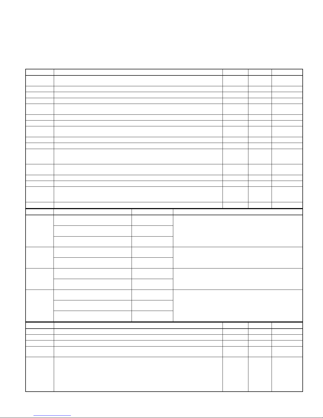
320893-101 REV. A
A94169
Fig. 1—Service Information Label
—7—
START HERE—IF A PROBLEM EXISTS, THE SERVICE TECHNICIAN SHOULD ALWAYS BEGIN TROUBLESHOOTING HERE.
SPECIAL NOTE: ALL VOLTMETERS ARE NOT THE SAME; YOUR VOLTAGE READINGS WILL VARY. THIS APPLIES TO THE
ENTIRE CONTENT OF THIS TROUBLESHOOTING MANUAL. THEY ARE NOT ABSOLUTE VALUES. CORRECT 115-VAC
VOLTAGE, CURRENT, AND POWER MEASUREMENTS CANNOT BE MADE ON ICM FURNACES UNLESS USING A TRUE RMS
METER.
STEP ACTION YES NO GO TO
Remove control door first. DO NOT REMOVE BLOWER DOOR! Removing
1.
2. Is RED LED status light blinking rapidly without a pause? 3 4 —
3. Go to page number indicated in Index for RAPID FLASHING LED. — — INDEX
4.
5.
6. Go to page number indicated in Index for section covering the status code. — — INDEX
7.
8.
9.
10. Does problem appear to be low cooling airflow? 11 12 —
11.
12.
13. Does furnace respond to the call for heat? 14 28 —
14.
15.
16.
17.
18.
19. Make sure power is being supplied to furnace. — — 20
20.
21.
22. Do you have 115 vac across L1 and L2? 24 23 —
23.
24. Do you have 24 vac across SEC-1 and SEC-2? 25 26 —
25. Replace 2-stage furnace control. — — 18
26. Do you have 115 vac across PR1 and PR2? 27 25 —
27.
28. Do you have 24 vac across W/W1 and C
29.
blower door interrupts power (115-vac or 24-vac) and erases previous status
codes stored in memory.
Is RED LED status light on?
Is RED LED status light blinking ON/OFF slowly with a combination of short and
long flashes?
Determine status code. The status code is a 2 digit number with the first digit
determined by the number of short flashes and the second digit by the number
of long flashes.
To retrieve previous codes, no thermostat inputs to control must be present and
all time delays must have expired. Disconnect 1 of the RED main limit wires 1
to 4 sec until RED LED status light goes out, then reconnect it and read status
code. To recover additional codes repeat this procedure. The 2-stage furnace
control is capable of retaining 5 previous status codes.
NOTE: DO NOT leave RED wire disconnected for longer than 4 sec as control
will assume an over-temperature condition exists and will respond with indoor
blower operation.
Was there a previous status code other than code 11?
NOTE: Status codes are erased after 48 hr or whenever power (115-vac or 24vac) is interrupted.
Go to page number indicated in Index for section covering the first previous status code.
Go to page number indicated in Index for section covering IMPROPER COOLING AIRFLOW.
Set thermostat to call for heat and set thermostat fan control to AUTO position if
equipped.
Observe operation of furnace for 20 minutes or until RED LED status light starts
blinking.
Does RED LED status light blink ON/OFF slowly with a combination of short
and long flashes?
Is temperature rise below range specified on rating plate when unit is operating
in high heat?
NOTE: If temperature rise is above range specified on rating plate, refer to
Start-Up and Adjustment section in Installation, Start-Up, and Operating Instructions.
Go to page number indicated in Index for section covering HIGH HEAT TEMPERATURE RISE TOO LOW (COLD BLOW).
Go to page number indicated in Index for CLEANUP AND START-UP INSTRUCTIONS.
Check fuses, breakers, or manual disconnects to be sure they are correctly set.
If not, reset them and go back to Step 1.
Remove blower door and depress door switch. Use a piece of tape to hold
switch closed.
Turn power off. Check continuity of power leads and door switch. If necessary
repair power leads and/or replace door switch.
Replace transformer. If transformer fails again, replace transformer and 2-stage
furnace control.
OM-24V on 2-stage furnace control? 25 29 —
You have a defective thermostat or a break in wiring between thermostat and
furnace. Fix problem.
219 —
57 —
—— 6
—— 8
910 —
— — INDEX
— — INDEX
—— 13
—— 15
516 —
17 18 —
— — INDEX
— — INDEX
—— 21
—— 22
—— 18
—— 18
—— 18
—8—
RAPID FLASHING LED—INDICATES LINE VOLTAGE POLARITY IS REVERSED, OR THE TRANSFORMERS ARE OUT OF
PHASE IN TWINNED UNITS.
STEP ACTION YES NO GO TO
1. Is this furnace twinned with another furnace? 7 2 —
2.
3. Do you have 115 vac across L2 and chassis ground? 4 6 —
4. Line voltage polarity is reversed. Fix problem. — — 5
5.
6. Replace 2-stage furnace control. — — 5
7.
8. Is RED LED status light blinking rapidly in only 1 of the twinned units? 9 16 —
9. Are fuses, breakers, or manual disconnects to problem unit correctly set? 11 10 —
10. Fix problem. —— 5
11. Are Master and Slave Auxiliary Limit switches properly set? 12 10 —
12. Do you have 115 vac across L1 and L2 in problem unit? 13 15 —
13. Do you have 24 vac across SEC-1 and SEC-2 in problem unit? 6 14 —
14. Replace transformer. — — 5
15.
16.
17.
18.
19.
Remove blower door and depress door switch. Use a piece of tape to hold
switch closed.
Go to page number indicated in Index for CLEANUP AND START-UP INSTRUCTIONS.
Remove blower doors and depress door switch in each unit. Use tape to hold
switches closed.
Turn power off to both units. Check continuity of power leads and door switch in
problem unit. If necessary repair power leads and/or replace door switch in
problem unit.
Check furnace circuit breaker location in service panel.
On single-phase (residential) systems, each furnace circuit breaker should be
located directly across from each other in service panel, or each furnace circuit
breaker should be located on the same side of service panel, but must skip 1
space to be connected to the same leg of the 1-phase power supply.
On 3-phase (commercial) systems, each furnace circuit breaker should be located directly across from each other in service panel, or each furnace circuit
breaker should be located on the same side of service panel, but must skip 2
spaces to be connected to the same leg of the 3-phase power supply.
Check 115-vac power lead connections at 2-stage furnace control of each furnace. The BLACK lead goes to L1 and the WHITE lead goes to L2.
Check 115-vac transformer lead connections at 2-stage furnace control of each
furnace. The BLACK lead goes to PR1 and the WHITE lead goes to PR2.
If circuit breaker location and 115-vac wiring is correct, reverse transformer secondary lead connections SEC-1 and SEC-2 in master furnace.
—— 3
— — INDEX
—— 8
—— 5
—— 17
—— 18
—— 19
—— 5
IMPROPER COOLING AIR FLOW—GENERALLY, THIS INDICATES THE Y/Y2 THERMOSTAT LEAD IS NOT CONNECTED TO
Y/Y2 AT FURNACE, OR BLOWER MOTOR HAS FAILED.
STEP ACTION YES NO GO TO
1.
2.
3. Make sure thermostat fan control is in AUTO position if equipped. — — 4
4. Do you have 24 vac across Y/Y2 and C
5.
6. Fix problem. —— 7
7.
8. Does blower motor turn on? Wait several sec to verify. 31 9 —
9. Remove tape from door switch and turn power off at main disconnect. — — 10
10. Does blower wheel rub against blower housing? 6 11 —
11. Does blower wheel turn freely? 12 13 —
12. Is blower wheel firmly mounted on motor shaft? 14 6 —
13.
14.
15.
16. Make sure thermostat fan control is in AUTO position if equipped. — — 17
17. Does furnace have a variable-speed ICM blower motor? 18 24 —
Remove blower door and depress door switch. Use a piece of tape to hold
switch closed.
Set thermostat to call for cooling. If thermostat does not have G connection,
jumper across thermostat terminals R and G.
OM-24V on 2-stage furnace control? 8 5
You have a defective thermostat, or a break in wiring between thermostat and
furnace, or the Y/Y2 thermostat terminal is not wired to thermostat.
Go to page number indicated in Index for CLEANUP AND START-UP INSTRUCTIONS.
Replace blower motor. On variable-speed ICM blower motors, inspect electronics portion of failed motor for water damage. If present, find source of water and
fix. Check A-coil and/or humidifier.
Turn power back on. Depress door switch. Use a piece of tape to hold switch
closed.
Set thermostat to call for cooling. If thermostat does not have G connection,
jumper across thermostat terminals R and G.
—— 2
—— 3
—— 6
— — INDEX
—— 7
—— 15
—— 16
—9—
STEP ACTION YES NO GO TO
18. Do you have 115 vac across BLACK and WHITE power leads at blower motor. 20 19 —
19.
STEP TERMINAL CONNECTIONS* VOLTAGE ACTION
20.
21.
22.
23.
STEP ACTION YES NO GO TO
24. Do you have 115 vac across HI-COOL and high voltage COMMON? 26 25 —
25. Replace 2-stage furnace control. — — 7
26. Remove tape from door switch and turn power off at main disconnect. — — 27
27.
28.
29.
30.
31. Does furnace have a variable-speed ICM blower motor? 34 32 —
32. Do you have 115 vac across HI-COOL and high voltage COMMON? 33 25 —
33.
STEP TERMINAL CONNECTIONS* VOLTAGE ACTION
34.
35.
36.
37.
STEP ACTION YES NO GO TO
38.
39.
40.
You have an open wire or bad terminal on either the BLACK or WHITE wire
between 2-stage furnace control and blower motor, or the power choke (if
equipped) failed. Fix problem.
PL4-1
YELLOW (+)
PL4-2
BLUE (+)
PL4-5
RED (+)
PL7-2
YELLOW (+)
PL7-12
BLUE (+)
PL7-13
RED (+)
PL7-1
YELLOW (+)
PL7-11
GREEN (+)
PL7-14
RED (+)
PL9-14
YELLOW (+)
PL9-15
GREEN (+)
PL9-12
RED (+)
Note location of all blower leads, then disconnect blower motor leads from
2-stage furnace control and capacitor.
Do you have continuity between the following motor leads:
• RED to WHITE
• YELLOW to WHITE
• BROWN to BROWN
• BLUE to WHITE
• BLACK to WHITE
• BROWN to WHITE
Replace capacitor. If problem still exists after replacing capacitor, replace
blower motor.
Replace blower motor. If problem still exists after replacing blower motor, replace capacitor.
• Check blower motor speed selection. Refer to Appendix E to evaluate external
static.
• Check filter(s) and ductwork for restrictions.
• Check outdoor unit for correct suction pressure and verify charge.
PL4-1
YELLOW (+)
PL7-2
YELLOW (+)
PL7-1
YELLOW (+)
PL9-14
YELLOW (+)
Is YELLOW COOL SIZE jumper on EZ-SELECT airflow control set to match
needed tons for cooling or heat pump system? (See Table 1.)
Set YELLOW COOL SIZE jumper on EZ-SELECT airflow control to match
needed tons for cooling or heat pump system? (See Table 1.)
Note position of GREEN CONTINUOUS-FAN CFM jumper on EZ-SELECT airflow control, then disconnect it.
to
to
to
to
to
to
to
to
to
to
to
to
to
to
to
to
PL4-3
BLACK (-)
PL4-3
BLACK (-)
PL4-3
BLACK (-)
PL7-10
BLACK (-)
PL7-10
BLACK (-)
PL7-10
BLACK (-)
PL7-8
BLACK (-)
PL7-8
BLACK (-)
PL7-9
BLACK (-)
PL9-3
BLACK (-)
PL9-3
BLACK (-)
PL9-1
BLACK (-)
PL4-3
BLACK (-)
PL7-10
BLACK (-)
PL7-8
BLACK (-)
PL9-3
BLACK (-)
-5 vdc to -10 vdc
-5 vdc to -13 vdc
24 vac
-5 vdc to -10 vdc
-5 vdc to -13 vdc
24 vac
-5 vdc to -10 vdc
5 vdc to 10 vdc
24 vac
-5 vdc to -10 vdc
5 vdc to 10 vdc
24 vac
-5 vdc to -10 vdc
-5 vdc to -10 vdc
-5 vdc to -10 vdc
-5 vdc to -10 vdc
If voltages are correct, go to Step 21. If not, replace 2-stage
furnace control.
If voltages are correct, go to Step 22. If not, repair or replace
ICM blower harness.
If voltages are correct, go to Step 23. If not, replace EZSELECT airflow control.
If voltages are correct, replace ICM blower motor. If not, repair
or replace ICM blower harness.
If voltages are correct, go to Step 35. If not, replace 2-stage
furnace control.
If voltages are correct, go to Step 36. If not, repair or replace
ICM blower harness.
If voltages are correct, go to Step 37. If not, replace EZSELECT airflow control.
If voltages are correct, go to Step 38. If not, repair or replace
ICM blower harness.
—— 7
—— 28
29 30 —
—— 7
—— 7
—— 7
40 39 —
—— 7
—— 41
—10—
STEP ACTION YES NO GO TO
41. Disconnect Y/Y2 thermostat lead from 2-stage furnace control. — — 42
42.
43.
Does blower motor change speed after Y/Y2 thermostat lead was disconnected
from 2-stage furnace control?
Reconnect GREEN CONTINUOUS-FAN CFM jumper on EZ-SELECT airflow
control to position noted earlier.
45 43 —
—— 44
44. Replace ICM blower motor. — — 7
45.
46.
* (+) and (-) designate Volt Ohm Meter Leads
Reconnect GREEN CONTINUOUS-FAN CFM jumper on EZ-SELECT airflow
control to position noted earlier.
• Check filter(s) and ductwork for restrictions.
• Check outdoor unit for correct suction pressure and verify charge.
—— 46
—— 7
TABLE 1—COOLING AND HEAT PUMP SIZE SELECTIONS
TONS (12,000 BTUH) 1-1/2 2 2-1/2 3 3-1/2 4 5
Upflow/Horizontal
Unit Size
COOL SIZES (YELLOW WIRE)
036060 LO M-LO M-HI HI — — —
048080 — — LO M-LO M-HI HI —
060100 — — — LO M-LO M-HI HI
060120 — — — LO M-LO M-HI HI
NOTE: Confirm CFM/ton selection on EZ-SELECT airflow control.
HIGH-HEAT TEMPERATURE RISE TOO LOW—GENERALLY, THIS INDICATES THE HI SOLENOID IN GAS VALVE GV HAS
FAILED OR FURNACE IS EXTREMELY UNDERFIRED.
STEP ACTION YES NO GO TO
Remove blower door. Make sure thermostat is NOT calling for heat. Note current settings for setup switches SW-1 and SW-2, then set SW-1 and SW-2 to
1.
2. Depress door switch. Use a piece of tape to hold switch closed. — — 3
3. Set thermostat to call for heat or jumper R and W/W1 thermostat terminals. — — 4
4.
5.
6. Is high-heat rate approximately the same as low-heat rate? 7 11 —
7.
8.
9.
10. Replace gas valve. —— 9
11. Is high-heat rate within 2% of that specified on rating plate? 13 12 —
12.
13. Is outdoor condensing unit operating during heating cycle? 16 14 —
14.
15. Check return air ducts in unheated spaces for leaks. — — 9
16. Fix problem. —— 9
OFF position.
On variable-speed units, check VIOLET wire pin connection on EZ-SELECT
airflow control for conformance with PIN marked on lower right of furnace rating
plate. Set RED gas heat temperature rise jumper on MID.
When furnace is running in low heat, clock low-heat gas rate. You have 16 minutes on this first call for heat before unit switches to high heat. On propane installations, check manifold pressure.
When furnace is running in high heat, clock high-heat gas rate. On propane installations, check manifold pressure.
Do you have 24 vac across gas valve terminals HI and C
OM-24V on 2-stage fur-
nace control during high heat?
You have an open wire or bad terminal on BROWN wire from high-heat pres-
sure switch HPS to gas valve GV. Repair it or replace harness.
Go to page number indicated in Index for CLEANUP AND START-UP IN-
STRUCTIONS.
Ensure gas inlet pressure and burner orifice are correct, then adjust gas valve
to proper rate. If it cannot be adjusted to proper rate, replace gas valve.
Check temperature rise and external static pressure with blower door in place.
Temperature rise should be mid-range or higher than midpoint of range stated
on furnace rating plate. External static pressure must not exceed 0.5 in. wc for
PSC and 0.7 in. wc for ICM motors. If return temperature is below 60°F, condensation may form on heat exchangers. If left uncorrected, failure will result.
—— 2
—— 5
—— 6
10 8 —
—— 9
— — INDEX
—— 9
—— 15
—11—
Status Code 11
NO PREVIOUS CODE—STORED STATUS CODES ARE ERASED AFTER 48 HR OR WHENEVER POWER SOURCE (115-VAC
OR 24-VAC) IS INTERRUPTED. RUN SYSTEM THROUGH A HEATING OR COOLING CYCLE TO CHECK SYSTEM.
Status Code 12
BLOWER ON AFTER POWERUP—BLOWER WILLRUN FOR90 SEC WHEN FURNACEPOWER ISINTERRUPTED ANDLATER
RESTORED DURING A CALLFOR HEAT(R-W/W1 CLOSED).IF THISSTATUS CODEREPEATS EVERYCOUPLE OFMINUTES,
IT IS PROBABLY CAUSED BY A DIRECT SHORT IN PRESSURE SWITCH CIRCUITS, GAS VALVEGV, WIRING TO GASVALVE
GV, OR HUMIDIFIER COIL.
STEP ACTION YES NO GO TO
1.
2. Depress door switch. Use piece of tape to hold switch closed. — — 3
3.
4.
5.
6. Do you have less than 90 vac across PR1 and PR2 on 2-stage furnace control? 7 10 —
7.
8. Fix problem. —— 9
9.
10. Disconnect R thermostat lead. — — 11
11.
12. Replace transformer. — — 9
13.
14. Does hot surface ignitor HSI come on during cycle? 15 19 —
15. Disconnect humidifier lead from HUM terminal on 2-stage furnace control. — — 16
16.
17.
18.
19. There is a direct short in YELLOW wire from low-heat pressure switch LPS. — — 8
20. While unit is operating in low heat, jumper R and W2 thermostat terminals. — — 21
21.
22. Disconnect BROWN wire to gas valve GV. — — 23
23. Does furnace still abruptly shut down as described in Step 21? 25 24 —
24. Replace gas valve. —— 9
25.
26.
Remove blower door and disconnect W/W1 thermostat lead from 2-stage furnace control.
Set thermostat to call for heat and set thermostat fan control to AUTO position if
equipped. Reconnect W/W1 thermostat lead to 2-stage furnace control.
Does furnace keep repeating the following cycle?
Induced draft motor IDM runs, induced draft motor IDM stops, blower motor
BLWM runs for 90 sec while RED LED status light flashes status code 12.
Do you have less than 17 vac across R and C
trol?
Make sure wire gage between main fuse box and furnace complies with wire
size specification in Installation, Start-Up, and Operating Instructions.
Go to page number indicated in Index for CLEANUP AND START-UP INSTRUCTIONS.
Do you have less than 19 vac across R and C
trol?
The thermostat and/or thermostat wires are loading down transformer. Replace
thermostat or repair thermostat wires.
Does furnace still alternately cycle induced draft motor IDM and blower motor
BLWM as described in Step 4.
There is a direct short in wiring to humidifier solenoid coil, diode bridge (if
used), or humidifier solenoid coil.
There is a short in gas valve GV or wiring to gas valve GV. Refer to Appendix
G to check gas valve GV.
Does furnace abruptly shut down with no inducer post-purge and then run
blower motor BLWM for 90 sec while RED LED status light flashes status code
12.
There is a direct short to ground in GRAY or BROWN wires connected to highheat pressure switch HPS.
Power to furnace was probably interrupted, or line voltage was too low during a
call for heat. This is normal operation. Go to page number indicated in Index for
CLEANUP AND START-UP INSTRUCTIONS.
OM-24V on 2-stage furnace con-
OM-24V on 2-stage furnace con-
—— 2
—— 4
520 —
614 —
—— 8
— — INDEX
12 13 —
—— 9
18 17 —
—— 8
—— 8
22 26 —
—— 8
— — INDEX
—12—
Status Code 13
LIMIT (LS) OR FLAME ROLLOUT (FRS) SWITCH LOCKOUT—THIS STATUS CODE INDICATES THAT LIMIT SWITCH OPENED
5 TIMES FOR AT LEAST 3 MINUTESEACH TIME DURING 1 THERMOSTAT CYCLE. THE 2-STAGE FURNACE CONTROL WILL
AUTO-RESET IN 3 HR. FLAME ROLLOUT SWITCH FRS REQUIRES MANUAL-RESET.
STEP ACTION YES NO GO TO
1.
2. Depress door switch. Use piece of tape to hold switch closed. — — 3
3. Set thermostat to call for heat or jumper R and W/W1 thermostat terminals. — — 4
4. Does blower motor turn on within 1 minute of ignition? 28 5 —
5.
6. Does blower wheel rub against blower housing? 7 9 —
7. Fix problem. —— 8
8.
9. Does blower wheel turn freely? 10 11 —
10. Is blower wheel firmly mounted on motor shaft? 12 7 —
11.
12.
13. Does furnace have a variable-speed ICM blower motor? 14 21 —
14. Do you have 115 vac across BLACK and WHITE power leads at blower motor. 16 15 —
15.
16. Wait 1 minute after burners ignite before proceeding to step 17. — — 17
STEP TERMINAL CONNECTIONS* VOLTAGE ACTION
17.
18.
19.
20.
STEP ACTION YES NO GO TO
21. Do you have 115 vac across LO-GAS-HEAT and high voltage COMMON? 23 22 —
22. Replace 2-stage furnace control. — — 8
23. Remove tape from door switch and turn power off at main disconnect. — — 24
24.
25.
Remove blower door. Make sure thermostat is NOT calling for heat. This action
resets control.
Remove tape from door switch, turn power off at main disconnect, and remove
jumper across R and W/W1.
Go to page number indicated in Index for CLEANUP AND START-UP INSTRUCTIONS.
Replace blower motor. On variable-speed ICM blower motors, inspect electronics portion of failed motor for water damage. If present, find source of water and
fix. Check A-coil and/or humidifier.
Turn power back on. Depress door switch. Use a piece of tape to hold switch
closed, then jumper R and W/W1 thermostat terminals.
You have an open wire or bad terminal on either the BLACK or WHITE wire
between 2-stage furnace control and blower motor, or the power choke (if
equipped) failed. Fix problem.
HUM
WHITE (+)
PL4-2
BLUE (+)
PL4-5
RED (+)
PL7-12
BLUE (+)
PL7-13
RED (+)
PL7-11
GREEN (+)
PL7-14
RED (+)
PL9-2
WHITE (+)
PL9-15
GREEN (+)
PL9-12
RED (+)
Note location of all blower leads, then disconnect blower motor leads from
2-stage furnace control and capacitor.
Do you have continuity between the following motor leads:
• RED to WHITE
• YELLOW to WHITE
• BROWN to BROWN
• BLUE to WHITE
• BLACK to WHITE
• BROWN to WHITE
to
to
to
to
to
to
to
to
to
to
C
OM-24V
(-)
PL4-3
BLACK (-)
PL4-3
BLACK (-)
PL7-10
BLACK (-)
PL7-10
BLACK (-)
PL7-8
BLACK (-)
PL7-9
BLACK (-)
PL9-3
BLACK (-)
PL9-3
BLACK (-)
PL9-1
BLACK (-)
24 vac
-5 vdc to -13 vdc
24 vac
-5 vdc to -13 vdc
24 vac
5 vdc to 10 vdc
24 vac
24 vac
5 vdc to 10 vdc
24 vac
If voltages are correct, go to Step 18. If not, replace 2-stage
furnace control.
If voltages are correct, go to Step 19. If not, repair or replace
ICM blower harness.
If voltages are correct, go to Step 20. If not, replace EZSELECT airflow control.
If voltages are correct, replace ICM blower motor. If not, repair
or replace ICM blower harness.
—— 2
—— 6
— — INDEX
—— 8
—— 13
—— 8
—— 25
26 27 —
—13—
STEP ACTION YES NO GO TO
26.
27.
28. Does furnace have a variable-speed ICM blower motor? 30 29 —
29.
STEP TERMINAL CONNECTIONS* VOLTAGE ACTION
30.
31.
STEP ACTION YES NO GO TO
32.
33.
34. Replace ICM blower motor. — — 8
* (+) and (-) designate Volt Ohm Meter Leads
Replace capacitor. If problem still exists after replacing capacitor, replace
blower motor.
Replace blower motor. If problem still exists after replacing blower motor, replace capacitor.
Lockout was caused by excessive return-air restriction. Check filter and returnair grilles for blockage. Add more return-air openings if necessary. Use Appendix E to evaluate external static pressure.
HUM
WHITE (+)
PL9-2
WHITE (+)
Make sure blower off delay is set to 135 sec or more, then disconnect W/W1
thermostat lead from 2-stage furnace control.
Does blower motor change speed 90 sec after W/W1 thermostat lead was disconnected from 2-stage furnace control.
to
to
C
OM-24V
(-)
PL9-3
BLACK (-)
24 vac
24 vac
If voltages are correct, go to Step 31. If not, replace 2-stage
furnace control.
If voltages are correct, go to Step 32. If not, repair or replace
ICM blower harness.
—— 8
—— 8
—— 8
—— 33
29 34 —
Status Code 14
IGNITION LOCKOUT—THIS STATUS CODE INDICATES FURNACE FAILED TO IGNITE GAS AND/OR PROVE FLAME IN 4
ATTEMPTS. THE 2-STAGE FURNACE CONTROL WILL AUTO-RESET IN 3 HR. REFER TO STATUS CODE 34.
Status Code 21
GAS HEATING LOCKOUT—THIS STATUS CODE INDICATES MAIN GAS VALVE RELAY MGVR ON 2-STAGE FURNACE
CONTROL IS STUCK CLOSED, OR THERE IS A MISWIRE/SHORT TO GAS VALVE WIRING. THE 2-STAGE FURNACE
CONTROL WILL NOT AUTO-RESET.
STEP ACTION YES NO GO TO
1. Turn power off and set thermostat to OFF position. Then turn power back on. — — 2
2. Does status code 21 flash? 3 6 —
3. There is a miswire or short to gas valve wiring. — — 4
4. Fix problem. —— 5
5.
6. Does a different status code flash? 7 8 —
7. Go to page number indicated in Index for section covering the status code. — — INDEX
8.
9. Jumper R and W/W1 thermostat terminals. — — 10
10. Does status code 21 start flashing when low-heat pressure switch LPS makes? 11 12 —
11. Replace 2-stage furnace control. — — 5
12. Does a different status code flash? 7 13 —
13.
14. Jumper R, W/W1, and W2 thermostat terminals on 2-stage furnace control. — — 15
15.
16. Replace gas valve. —— 5
17. Cycle furnace several times to check for intermittent operation. — — 18
Go to page number indicated in Index for CLEANUP AND START-UP INSTRUCTIONS.
Remove blower door and depress door switch. Use a piece of tape to hold
switch closed.
Disconnect jumper wire across R and W/W1 thermostat terminals and wait until
blower stops.
Does status code 21 start flashing when high-heat pressure switch HPS
makes?
— — INDEX
—— 9
—— 14
16 17 —
—14—
 Loading...