

Page 1
PLUS 80t with Perfect Heat™
DOWNFLOW
California Approved
331JAV
Sizes 060 thru 100
INDUCED-COMBUSTION FURNACE
The Plus 80t Downflow Furnace achieves 80 percent Annual
Fuel Utilization Efficiency (AFUE) rating. The benefits of Perfect
Heat operation in reducing sound and improving comfort put it in
a class well ahead of the competition. The Plus 80t has the kind
of overall performance needed in today’s homes. All models are
GAMA efficiency rating certified and certified for use in California
Air Quality Management Districts.
FEATURES
EFFICIENCY — The Plus 80t Induced-Combustion Gas Fur-
nace provides the efficiency customers want with 80.0% AFUE.
HOT SURFACE IGNITION — No pilot to waste gas with this
field-proven ignition system.
ALUMINIZED HEAT EXCHANGER — The patented 4-pass
heat exchanger is made of aluminized steel and backed by a
20-year Limited Warranty.
INTELLIGENT CONTROL — The Plus 80t has an intelligent
control that monitors the operation of the furnace. This control
also has a component-test feature that enables the servicing
technician to verify operation of the control; the high and low inducer; the hot surface ignitor; and high-, medium-, and lowspeed blower operation. The control features a 3-amp fuse that
protects the transformer and control. We guarantee the reliability
of the control with a 3-year Limited Warranty.
40-IN. HEIGHT — The Plus 80t cabinet height is only 40 in.
This simplifies installation in alcoves, attics, basements (ideal
for short basement), closets, and utility rooms, especially with
a taller high-efficiency cooling coil.
PREPAINTED CABINET — The Plus 80t uses prepainted sheet
metal for the cabinet. This is the same high-quality finish found
on refrigerators and other appliances today. We ensure its durability by using a galvanized steel substrate to provide superior
rust protection.
PATENTED BLOCKED VENT SAFEGUARD — Our induced-
combustion furnace has a patented blocked vent safeguard. The
safeguard switch will stop furnace operation if the vent system
becomes blocked or is not operating properly. An exclusive with
the Plus 80t furnace.
EASY INSTALLATION — The Plus 80t has many features that
make installation easier: left or right gas and electrical connections, heating and cooling blower speed selector, matching coil
sizes, accessory low-voltage connections, and many more.
QUIET OPERATION — A soft mount inducer assembly and 2-
stage slow-opening gas valve reduce sound level. The Perfect
Heat operation capability minimizes furnace and air noise for
total home comfort.
Series C
Form No. PDS 331J.60.4
Page 2
*
1
28
⁄2″
20″
13
⁄16″
7
39
⁄8″
11
⁄16″
INLET
7
⁄8″ DIA
ACCESSORY
3
1
⁄4″ DIA HOLE
GAS ENTRY
OUTLET
19″
ADDITIONAL
NOTE:
LOCATED IN THE TOP PLATE
AND BOTTOM PLATE
NOTES:
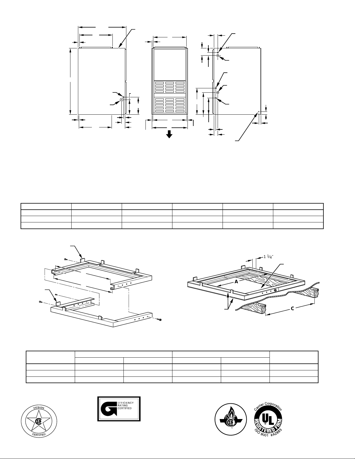
1. Two additional 7⁄8-in. dia holes are located in the top plate.
2. Minimum return-air openings at furnace, based on metal duct. If flex duct is used,
see flex duct manufacturer's recommendations for equivalent diameters.
a. For 800 CFM–16-in. round or 14
b. For 1200 CFM–20-in. round or 141⁄2 x 191⁄2-in. rectangle.
c. For 1600 CFM–22-in. round or 14
d. For airflow requirements above 1800 CFM, must use entire return air opening.
7
⁄8″ DIA K.O. ARE
VENT CONNECTION
13
⁄16″
1
9
⁄8″
1
10
⁄4″
1
1
⁄16″
1
2
⁄8″
1
8
⁄4″
11
⁄16″
AIRFLOW
D
E
A
DIMPLES TO DRILL HOLES
FOR HANGER BOLTS (4 PLACES)
IN HORIZONTAL POSITION
1
⁄2 x 12-in. rectangle.
1
⁄2 x 231⁄4-in. rectangle.
11
16
⁄16″
1
13
4
⁄16″
3
⁄16″
15
2
⁄16″
5
⁄16″
1
10
⁄4″
1
⁄2″ DIA
2″
THERMOSTAT
WIRE ENTRY
7
⁄8″ DIA
ACCESSORY
7
⁄8″ DIA HOLE
POWER ENTRY
1
1
⁄2″ DIA
R.H. GAS ENTRY
7
⁄8″ DIA
ACCESSORY
1
1
⁄16″
1
2
⁄8″
1
″ TYP
5
⁄8″ TYP
DIMENSIONS (In.)
UNIT SIZE A D E VENT CONN (Dia) SHIPPING WEIGHT (Lb)
036060 14-3/16 12-9/16 12-11/16 4 145
048080 17-1/2 15-7/8 16 4 154
060100 21 19-3/8 19-1/2 4 181
A99109
ACCESSORY DOWNFLOW SUBBASE
LOCATING
TAB
B
A
Assembled
LOCATING
TAB
D
Disassembled
4
3
2
1
FACTORY-SUPPLIED
3
4
A88207
1
2
FIELD-INSTALLED
INSULATION
DIMENSIONAL DATA (In.)
PLENUM OPENING *
FURNACE WIDTH
14-3/16 11-13/16 19 13-7/16 20-3/8 4
17-1/2 15-1/8 19 16-3/4 20-3/8 3
21 18-5/8 19 20-1/4 20-3/8 2
The plenum should be constructed 1/4 in. smaller in width and depth than the plenum dimensions shown above.
FRAMED FLOOR HOLE
1 1⁄4″ TYP
WIDTH ADJUSTMENTABCD
PLENUM
OPENING
C
A88206
HOLE NO. FOR
ama
MEETS DOE RESIDENTIAL CONSERVATION
SERVICES PROGRAM STANDARDS.
Before purchasing this appliance, read important
energy cost and efficiency information available
from your retailer.
CERTIFIED
—2—
Page 3

*
**
SPECIFICATIONS
UNIT SIZE 036060 048080 060100
RATINGS AND PERFORMANCE
Gas Input (Btuh) *
Output Capacity (Btuh)† High Stage 51,000 69,000 86,000
Nonweatherized ICS Low Stage 33,000 44,000 55,000
AFUE† Nonweatherized ICS 80.0 80.0 80.0
Certified Temperature Rise High Stage 30—60 30—60 35—65
Range (°F) Low Stage 15—45 15—45 20—50
Certified External Static Pressure Heat/Cool 0.10/0.50 0.15/0.50 0.20/0.50
Airflow CFM Heating High/Low 1195/1030 1355/1170 1735/1500
High Stage 63,000 84,000 105,000
Low Stage 40,500 54,000 67,500
Cooling 1195 1580 1950
ELECTRICAL
Unit Volts— Hertz— Phase 115—60—1
Operating Voltage Range Min—Max 104—127
Maximum Unit Amps 10.5 14.2 17.9
Maximum Wire Length (Measured 1 Way) Ft 35 26 32
Minimum Wire Size 14 12
Maximum Fuse Size 15 20
Transformer (24v) 40va
External Control Heating 19va
Power Available Cooling 35va
Air Conditioning Blower Relay Standard
CONTROLS
Limit Control SPST (Auto-Reset)
Heating Blower Control Solid-State Time Operation
Inducer 2-Speed
Burners (Monoport) 3 4 5
Gas Connection Size 1/2-in. NPT
GAS CONTROLS
2-Stage Redundant Gas Valve White-Rodgers
Min Inlet Pressure (In. wc) 4.5 (Natural Gas)
Max Inlet Pressure (In. wc) 13.6 (Natural Gas)
Ignition Device Hot Surface
BLOWER DATA
Direct-Drive Motor HP (PSC) 1/3 1/2 3/4
Motor Full Load Amps 5.1 7.4 11.0
RPM (Nominal)—Speeds 1075—5
Blower Wheel Diameter x Width (In.) 10 x 6 10 x 8 10 x 6
Filter Size (In.)—Permanent Washable (Supplied) (2) 14 x 20 x 1 (2) 16 x 20 x 1
DEALER-INSTALLED ACCESSORIES
Downflow Subbase **
High-Altitude Pressure Switch Kit‡ KGAH5601PSW
Gas Conversion Kit—Natural-to-Propane KGANP26012SP
Gas Conversion Kit—Propane-to-Natural KGAPN21012SP
Gas input ratings are certified for elevations to 2000 ft. For elevations above 2000 ft, reduce ratings 4% for each 1000 ft above sea level. Refer to National
Fuel Gas Code Table F4. In Canada, derate the unit 10% for elevations 2000 ft to 4500 ft above sea level.
† Capacity in accordance with U.S. Government DOE test procedures.
‡ 5500 ft and higher above sea level.
Required for installation on combustible floors when no coil box is used, or when any coil box other than a Bryant cased coil is used.
ICS—Isolated Combustion System
KGASB0201ALL
CONTROLS—THERMOSTATS AND ZONING
Auto Changeover, °F/°C, 1-Stage Heat/1-Stage cool — TSTATBBNAC01-B
Auto Changeover, °F/°C, 2-Stage Heat/1-Stage Cool — TSTATBBNHP01-B
THERMOSTAT—NON-PROGRAMMABLE
Auto Changeover, 7-Day Programmable, °F/°C, 1-Stage heat/1-Stage cool — TSTATBBPAC01-B
Auto Changeover, 7-Day Programmable, °F/°C, 2-Stage Heat/1-Stage Cool — TSTATBBPHP01-B
THERMOSTAT-PROGRAMMABLE
ZONING—2-ZONE ZONEBB2KIT01, ZONEKIT2ZBDP
ZONING—4-ZONE ZONEBB4KIT01
ZONING—8-ZONE ZONEBB8KIT01
Auto Changeover, °F/°C, 2-Stage Heat/2-Stage cool — TSTATBBN2S01-B
Air Conditioner, 1-Stage Heat/1-Stage Cool, Manual Changeover, °F/°C — TSTATBBBAC01
Heat Pump, 2-Stage Heat/1-Stage Cool. Manual Changeover, °F/°C — TSTATBBBHP01*
2-Stage Heat/2-Stage Cool in AC Mode, 3-Stage Heat/2-Stage Cool in HP Mode
Dual Fuel Thermostat. Includes Outdoor Air Temperature Sensor — TSTATBBPDF01-B*
Thermidistat™ Control — Non-Programmable/Programmable — TSTATBBPRH01-B*
Thermostat with Humidity Control (For use in Dual Fuel, AC, HP, and 2S applications.
in AC Mode, 3-Stage Heat/2-Stage Cool in HP Mode
Auto Changeover, 7-Day Programmable, °F/°C, — TSTATBBP2S01-B
Includes Outdoor Air Temperature Sensor.)
—3—
Page 4

UNIT
SIZE
036060 1/3 PSC
048080 1/2 PSC
060100 3/4 PSC
BLOWER
MOTOR HP SPEED
AIR DELIVERY— CFM (With Filter)
EXTERNAL STATIC PRESSURE (IN. WC)
0.1 0.2 0.3 0.4 0.5 0.6 0.7 0.8
High
Med-High
Med
Med-Low
Low
High
Med-High
Med
Med-Low
Low
High
Med-High
Med
Med-Low
Low
1435
1195
1030
900
705
1855
1595
1355
1170
880
2235
1995
1735
1510
1145
1385
1165
1020
890
700
1765
1570
1345
1170
865
2185
1970
1735
1500
1140
1320
1145
1010
875
690
1710
1530
1305
1140
855
2110
1915
1675
1485
1125
1265
1105
985
855
675
1665
1485
1270
1110
830
2030
1845
1625
1455
1115
1195
1070
955
835
655
1580
1410
1220
1075
805
1950
1765
1565
1400
1100
INSTALLATION
This unit is certified for downflow installation only. See Installation Manual for
important installation instructions.
MINIMUM INCHES CLEARANCE TO COMBUSTIBLE CONSTRUCTION
This forced air furnace is equipped for
use with natural gas at altitudes 0 10,000 ft
(0-3,050m).
An accessory kit, supplied by the
manufacturer, shall be used to convert to
propane gas use or may be required for
some natural gas applications.
This furnace is for indoor installation in
a building constructed on site.
This furnace may be installed on
combustible flooring in alcove or closet at
minimum clearance from combustible
material.
This furnace may be used with a Type
B-1 Vent and may be vented in common
with other gas-fired appliances.
For installation on non-combustible
†
floors only. For installation on
combustible flooring only when
installed on special base, Part No.
KGASB0201ALL, Coil Assembly,
Part No. CD5 or CK5, or Coil
Casing, Part No. KCAKC.
For furnaces wider than 14.25
#
inches (362mm) may be 0 inches.
Ø
18 inches front clearance required
for alcove.
For single wall vent type 6 inches.
##
This furnace is approved for DOWNFLOW installations only.
1"
0"
B
A
C
K
E
D
I
S
TOP / PLENUM
E
C
A
N
R
U
F
T
N
O
R
F
F
R
O
N
T
1" #
1"
BOTTOM
†
Clearance in inches.
Vent Clearance to combustibles:
For Single Wall vents 6 inches (6 po).
For Type B-1 vent type 1 inch (1 po).
##
1145
1015
915
795
625
1570
1355
1170
1025
755
1835
1680
1480
1320
1085
#
1"
E
D
I
S
S
E
R
V
I
C
E
30"
MIN
1080
955
860
755
580
1410
1280
1110
965
720
1700
1545
1370
1230
1045
1000
885
790
690
525
1310
1200
1025
890
655
1540
1415
1265
1130
990
Ø
322567-101 REV. E (LIT)
A97620
SPECIFICATIONS SUBJECT TO CHANGE WITHOUT NOTICE
UNIT MUST BE INSTALLED IN ACCORDANCE
WITH INSTALLATION INSTRUCTIONS
Cancels: PDS 331J.60.3
© 1999 Bryant Heating & Cooling Systems, 7310 W. Morris St. Indpls., IN 46231 PRINTED IN U.S.A. Catalog No. 5233-103 10-99
—4—
 Loading...