

Bryant 315AAV, 315JAV Quick Manual
Variable Speed
4-Way Multipoise
Induced Combustion
Gas Furnace
315AAV/315JAV
Sizes 045 thru 155
Series A
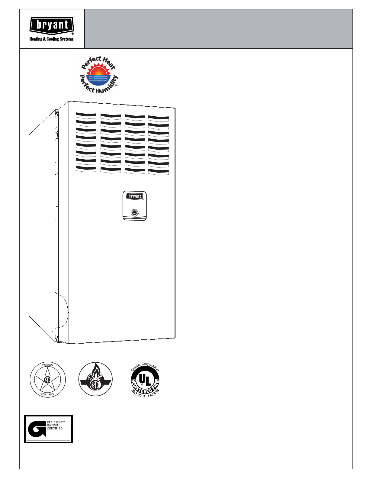
The 315AAV/JAV Variable-Speed 4-Way Multipoise
Gas Furnace offers outstanding comfort and
electrical efficiency in an 80% AFUE furnace. You
get all of the benefits of Perfect Heat
Humidity
TM
: reduced drafts, reduced sound levels,
TM
and Perfect
longer, more gentle cycles, and less temperature
differences between rooms. Also, it improves
indoor air quality, plus provides outstanding
electrical efficiency all year long: Homeowners
can now economically run constant fan to help
eliminate temperature differences throughout the
house and to get better indoor air quality. This
Perfect Humidity furnace also increases comfort in
the summer by wringing out extra humidity. The
315AAV/JAV furnaces are approved for use with
natural or propane gas, and the 315JAV is
approved for use in Low NOx Air Management
Districts.
ama
P
LUS
80
V
E
n
e
r
g
y E
ff
ic
ien
t
Ga
s F
u
r
n
a
ce
A01480
CERTIFIED
REGISTERED
QUALITY SYSTEM
MEETS DOE RESIDENTIAL CONSERVATION
SERVICES PROGRAM STANDARDS.
Before purchasing this appliance, read important
energy cost and efficiency information available
from your retailer.
STANDARD FEATURES
.
Perfect Heat, Perfect Humidity
Two-stage heating
Reduced operating sound through low-stage
operation and sound elimination combustion system
Variable-speed blower motor
Super-low electrical use, up to 80% less than
standard models
Increased SEER ratings for AC and HP systems
Matches CFM to cooling system at all static points
Provides full Perfect Heat/Perfect Humidity benefits
including "Super Dehumidify"
.
Four-position furnace: upflow, horizontal right,
horizontal left, downflow
Thirteen different vent options
.
Shorter in height - only 33
.
Media Filter Cabinet included
.
Microprocessor based "smart" control
center
Adapts heating stages to meet demand
Continuous Fan speed adjustable from thermostat
Adjustable heating air temperature rise
Up to 12 cooling airflow selections with a wide range
of capability
LED diagnostics, non-volatile fault code memory, and
self test feature
.
Patented blocked vent safeguard to ensure
proper furnace venting
.
All models are Chimney Friendly when used
with accessory vent kit
.
Insulated blower compartment
.
Heat pump compatible
.
Hot surface Ignition (HSI)
.
Residential installations eligible for
consumer financing through the Comfort
LIMITED WARRANTY
.
20-year warranty on "Super S
.
5-year parts warranty on all other components
operation
1
/3" tall
TM
" heat exchanger
Form No. PDS 315A.45.2
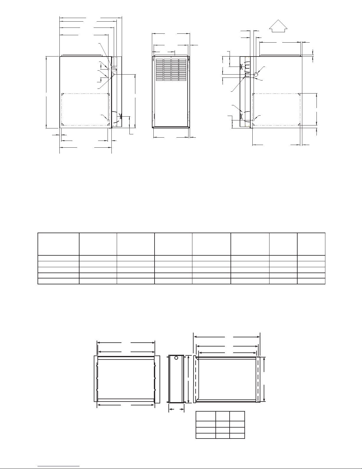
33-5/16"
E
VENT
28-7/8"
26-1/8"
(VENT CONNECTION)
25-1/4"
22-9/16"
JUNCTION BOX
LOCATION
7/8" DIA
ACCESSORY
1/2" DIA THERMOSTAT
WIRE ENTRY
3-15/16"
LEFT HAND GAS
ENTRY
7/8" DIA. ACCESSORY
24-7/8"
A
D
13/16"
F
JUNCTION BOX
LOCATION (TYP)
VENT OUTLET
5 PLACES (TYP)
1-9/16"
2-9/16"
4-13/16"
8-7/16"
1-7/16"
ALTERNATE
3-3/4"
AIRFLOW
19"
OUTLET
1-1/2" DIA.
RIGHT HAND
GAS ENTRY
1/2" DIA. THERMOSTAT
WIRE ENTRY
7/8" DIA. ACCESSORY
13/16"
11/16"
14-7/8"
11/16"
NOTES:
21-5/8"
BOTTOM INLET
24"
(CASING)
1. Two additional
7
/8
5-1/2"
1-11/16"
-in. dia knockouts are located in the top plate.
2. Minimum return-air openings at furnace, based on metal duct. If flex duct is used,
see flex duct manufacturer's recommendations for equivalent diameters.
3. Minimum return-air opening at furnace:
a. For 800 CFM-16-in. round or 14
b. For 1200 CFM-20-in. round or 14 x 19 -in. rectangle.
c. For 1600 CFM-22-in. round or 14 x 22 -in. rectangle.
d. For airflow requirements above 1800 CFM, see Air Delivery table in Product Data literature for specific
use of single side inlets. The use of both side inlets, a combination of 1 side and the bottom, or the
bottom only will ensure adequate return air openings for airflow requirements above 1800 CFM.
315AAV/315JAV
UNIT SIZE
036070
048090
060110
066135
066155
A
(CABINET
WIDTH)
14-3/16 12-9/16 12-11/16 9-5/16 4
17-1/2 15-7/8 16-1/8 11-9/16 4
21 19-3/8 19-1/2 13-5/16
24-1/2 22-7/8 23 15-1/16 4 (note 1)
24-1/2 22-7/8 23 15-1/16 4 (note 1)
D
(SUPPLY
WIDTH)
1) 135 and 155 size furnaces require five-inch
furnace and vent stack.
2) See Installation Instructions for complete
installation requirements.
E
1
/
x 12-in. rectangle.
2
1
1
/
/
2
1
/
2
1
/
2
16
(BOTTOM
RETURN
WIDTH)
11/16"
F
(C.L. TOP &
BOTTOM
VENT OUTLET)
CONNECTION
SIZE
(see notes 1 & 2)
4
vents. Use a 4-5 inch vent adapter between
1-1/4"
22-1/16"
SIDE INLET
SHIPPING
WEIGHT
127
151
162
177
183
1"
MEDIA
CABINET
SIZE
16
16
20
24
24
Centerline Screw Slots
23 "
3
/
22
4"
Furnace Side
1
/
23
8"
5
3
/
4"
-2-
A
Media/
Filter Cabinet
16" 17" 16"
20" 21" 20"
24" 25" 24"
25 "
3
/
23
4"
Opening with Flanges Bent
1
/
22
2"
Opening
Duct Side
A B
B Opening
A02210
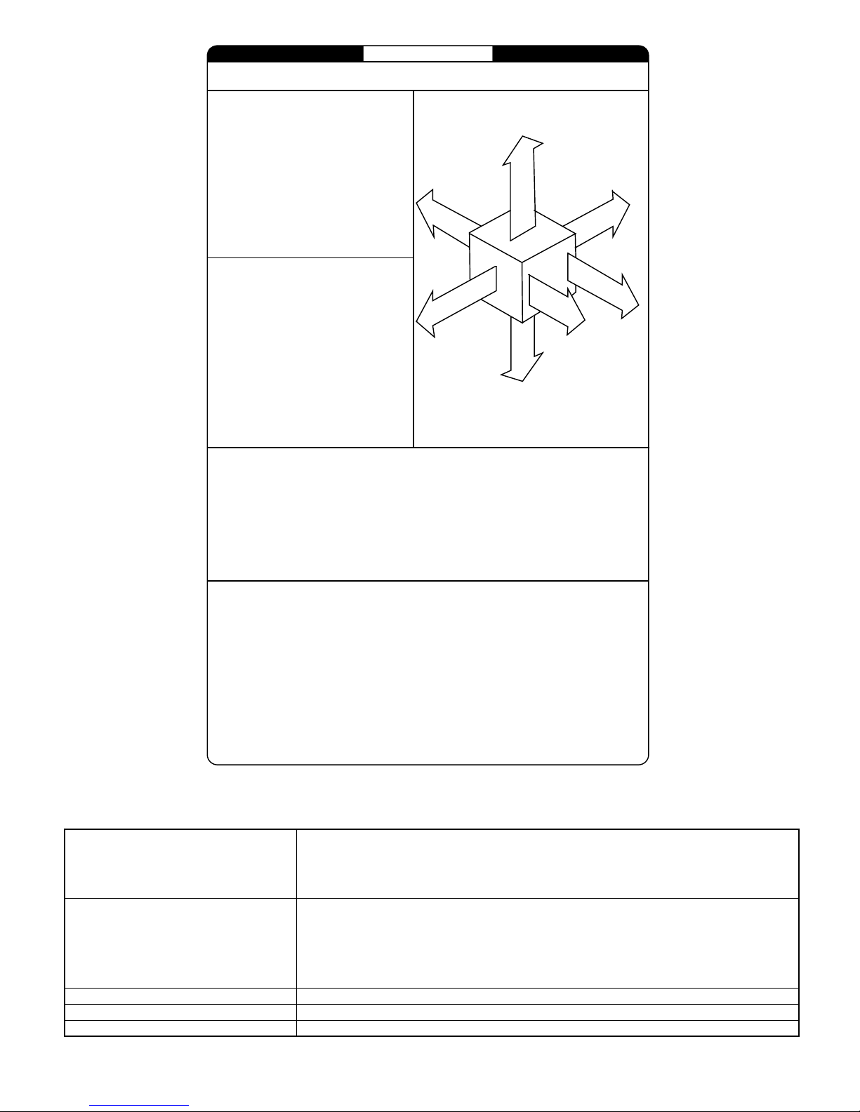
INSTALLATION
MINIMUM INCHES CLEARANCE TO COMBUSTIBLE CONSTRUCTION
DISTANCE MINIMALE EN POUCES AUX CONSTRUCTIONS COMBUSTIBLES
This forced air furnace is equi pped for use with
natural gas at altitudes 0-10,000 ft (0-3,050m).
An accessory kit, supplied by the
manufacturer,shall be used to convert to propane
gas use or may be required for some natural gas
applications.
This furnace i s for indoor installation in a
building constructed on site.
This furnace may be installed on combustible
flooring in alcove or closet at minimum clearance
as indicated by the diagram from combustible
material .
This furnace may be used with a Type B-1 Vent
and may be vented in common with other gasfired appliances.
Cette fournaise à air pulsé est équipée
pour utilisation avec gaz naturel et altitudes
comprises entre 0-3,050m (0-10,000 pi).
Utiliser une trousse de conversion, fournie par
le fabricant, pour passer au gaz propane ou pour
certaines installations au gaz naturel.
Cette fournaise est prévue pour être
installée dans un bâtiment construit sur place.
Cette fournaise peut être installée sur
un plancher combustible dans une alcôve ou
dans un garde-robe en respectant le minimum
d'espace libre des matériaux combustibles, tel
qu'indiqué sur le diagramme..
Cette fournaise peut être util isée avec un
conduit d´évacuation de Type B-1 ou connectée
au conduit commun d´autres appareils à gaz..
This furnace is approved f or UPFLOW, DOWNFLOW, and
HORIZONTAL install ations.
Cette fournaise est approuvée pour l´installation HORIZONTALE
et la circul ation d´air VERS LE HAUT et VERS LE BAS.
1"
Clearance arrows
do not change with
furnace orientation.
0"
B
A
A
C
R
K
R
I
È
R
E
E
D
I
S
É
T
Ô
C
0"
*
Vent Clearance to combustibles:
For Single Wall vents 6 inches (6 po).
For Type B-1 vent type 1 inch (1 po).
Dégagement de l´évent avec combustibles:
Pour conduit d´évacuation à paroi simple 6 po (6 inches).
Pour conduit d´évacuation de Type B-1 1 po (1 inch).
Les fléches de dégagement
ne changent pas avec
l´orientation de la fournaise.
TOP / PLE NUM
DESSUS / CHAMBRE D'AIR
E
C
E
A
S
N
I
A
R
U
N
F
R
U
T
FO
N
O
T
R
N
F
A
V
A
F
R
O
A
N
V
T
A
N
T
3"
MIN
Ø
DESSOUS
"
Clearance in inches
Dégagement (po).
BOTTOM
0
†
E
N
MINIMUM INCHES CLEARANCE TO COMBUSTIBLE CONSTRUCTION
DOWNFLOW POSITIONS:
Installation on non-combustible floors only.
†
For Installation on combustible flooring only when installed on special base, Part No. KGASB0201ALL,
Coil Assembly, Part No. CD5 or CK5, or Coil Casing, Part No. KCAKC.
18 inches front clearance required for alcove.
Ø
Indicates supply or return sides when furnace is in the horizontal position. Line contact only permissible
*
between lines formed by intersections of the Top and two Sides of the furnace jacket, and building joists,
studs or framing.
DÉGAGEMENT MINIMUM EN POUCES AVEC ÉLÉMENTS
DE CONSTRUCTION COMBUSTIBLES
POUR LA POSITION COURANT DESCENDANT:
Pour l ´i nstallation sur pl ancher non combustible seulement.
†
Pour l´installation sur un plancher combustible seulement quand on utilise la base spéciale, pièce
o
n KGASB0201ALL, l´ensemble serpentin, pièce n CD5 ou CK5, ou le carter de serpentin, pièce
o
n KCAKC.
Dans une alcôve, on doit maintenir un dégagement à l´avant de 18 po (450 mm).
Ø
La position indiquée concerne le côté d´entrée ou de retour quand la fournaise est dans la
*
position horizontale.
Le contact n´est permis qu´entre les lignes formées par l es intersections du dessus et des
deux côtés de la chemise de la fournaise et les solives, montant sous cadre de charpente.
o
327590-101 REV. B
0"
E
D
*
I
È
S
T
Ô
C
S
E
R
V
I
T
R
C
E
E
T
I
E
N
30"
MIN
THERMOSTAT- NON-PROGRAMMABLE
THERMOSTAT- PROGRAMMABLE
ZONING- 2-ZONE ZONEBB2KIT01-B, ZONEKIT2ZBDP
ZONING- 4-ZONE ZONEBB4KIT01-B
ZONING- 8-ZONE ZONEBB8KIT01-B
* Do not use in zoning heat pump applications.
CONTROLS-THERMOSTATS AND ZONING
Auto Changeover, oF/oC, 1-Stage Heat/1-Stage Cool - TSTATBBNAC01-B
Auto Changeover, oF/oC, 2-Stage Heat/1-Stage Cool - TSTATBBNHP01-B
Auto Changeover, oF/oC, 2-Stage Heat/2-Stage Cool - TSTATBBN2S01-B
Air Conditioner, 1-Stage Heat/1-Stage Cool, Manual Changeover, oF/oC - TSTATBBBAC01
Heat Pump, 2-Stage Heat/1-Stage Cool, Manual Changeover, oF/oC - TSTATBBBHP01
Auto Changeover, 7-Day Programmable, oF/oC, 1-Stage Heat/1-Stage Cool - TSTATBBPAC01-B
Auto Changeover, 7-Day Programmable, oF/oC, 2-Stage Heat/1-Stage Cool - TSTATBBPHP01-B
Auto Changeover, 7-Day Programmable, oF/oC, 2-Stage Heat/2-Stage Cool - TSTATBBP2S01-B
Dual Fuel Thermostat, includes Outdoor Air Temperature Sensor - TSTATBBPDF01-B
Thermidistat Control - Non-Programmable/Programmable Thermostat - TSTATBBPRH01-B *
with Humidity Control (For use in Dual Fuel, AC, HP, and 2S applications. Includes Outdoor Air
in AC Mode, 3-Stage Heat/2-Stage Cool in HP Mode
in AC Mode, 3-Stage Heat/2-Stage Cool in HP Mode
Temperature Sensor.)
-3-
*
*
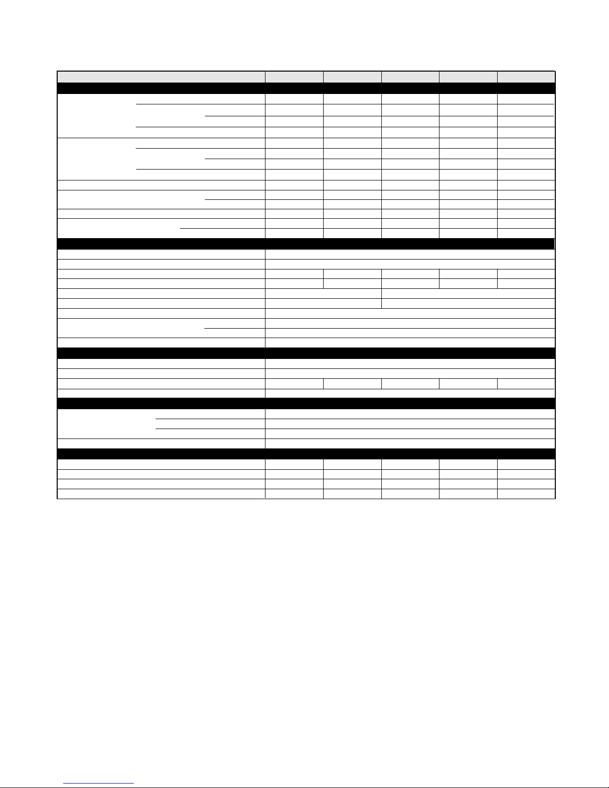
SPECIFICATIONS
UNIT SIZE
RATINGS AND PERFORMANCE
Input Btuh
Nonweatherized ICS
Output Capacity (Btuh)
Nonweatherized ICS
AFUE
Certified Temperature Rise Range oF
Certified External Static Pressure Heat/Cool
Airflow CFM ‡
ELECTRICAL
Unit Volts-Hertz-Phase
Operating Voltage Range Min-Max
Maximum Unit Amps
Maximum Wire Length (Measured 1 Way in Ft)
Minimum Wire Size
Maximum Fuse or Ckt Bkr Size (Amps)**
Transformer (24v)
External Control Heating
Power Available Cooling
Air Conditioning Blower Relay
CONTROLS
Limit Control
Heating Blower Control
Burners (Monoport)
Gas Connection Size
GAS CONTROLS
Gas Valve (Redundant)
Ignition Device
BLOWER DATA
Direct-Drive Motor HP (PSC)
Motor Full Load Amps
RPM (Nominal)-Speeds
Blower Wheel Diameter x Width (In.)
* Gas input ratings are certified for elevations to 2000 ft. For elevations above 2000 ft, reduce ratings 4 percent for each 1000 ft above sea level.
Refer to National Fuel Gas Code Table F4 or furnace Installation Instructions. In Canada, derate the unit 10 percent for elevations 2000 ft to
4500 ft above sea level.
** Time-delay type is recommended.
†
Capacity in accordance with U.S. Government DOE test procedures.
‡
Airflow shown is for bottom only return-air supply in comfort mode (as-shipped). For air delivery above 1800 CFM, see Air Delivery table for
other options. A filter is required for each return-air supply. An airflow reduction of up to 7% may occur when using the factory-specified 4-5/16-
inch wide, high efficiency media filter.
ICS-Isolated Combustion System
N/A-Not Applicable
*
†
315JAV Upflow; all 315AAV
315JAVDownflow/Horizontal
315JAV Upflow; all 315AAV
†
315JAVDownflow/Horizontal
Heating High/Low
Min Inlet Pressure (In. wc)
Max Inlet Pressure (In. wc)
-High
-Low
-High
-Low
-High
-Low
-High
-Low
High
Low
Cooling
036070 048090 060110 066135 066155
66,000
43,500
63,000
43,500
54,000 71,000 89,000 107,000 125,000
35,000
51,000 68,000 85,000 102,000 119,000
35,000
80.0 80.0 80.0 80.0 80.0
30-60 40-70
30-60 30-60 25-55 25-55 30-60
0.12/0.50 0.15/0.50 0.20/0.50 0.20/0.50 0.20/0.50
1060/615 1090/825 1330/1110 1725/1430
1225 1400 2095 2100 2095
9.0 9.6 15.1 14.9 15.0
30 29 29 30 29
3 4 5
1/2 1/2 1 1 1
7.7 7.7 12.8 12.8 12.8
300-1300 300-1300 300-1300 300-1300 300-1300
10 x 6 10 x 8 11 x 10 11 x 11 11x 11
14
15
88,000
58,000
84,000
58,000
47,000
47,000
Solid-State Time Operation
110,000
72,500
105,000
72,500 87,000
59,000
59,000
40-70
115-60-1
104-127
40va
12va
35va
Standard
SPST
1/2-in. NPT
White Rodgers
4.5 (Natural Gas)
13.6 (Natural Gas)
Hot Surface
132,000
87,000
126,000
70,000
70,000
40-70
12
20
6
154,000
101,500
147,000
101,500
82,000
82,000
45-75
1775/1440
7
-4-
 Loading...