

Page 1
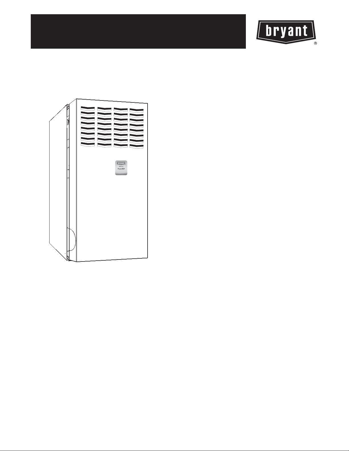
313AAV/JAV Plus 80x
4--WAY MULTIPOISE
INDUCED--COMBUSTION GAS FURNACE
INPUT CAPACITIES: 45,000 THRU 135,000 Btuh
Product Data
STANDARD FEATURES
S ECM blower motor included
S Noise elimination combustion system
S SmartEvapt can lower the humidity level in the home by
nearly 10%
S Four--position furnace: Upflow, Horizontal Right,
Horizontal Left, Downflow
Thirteen different vent options
S Compact design only 33--1/3 in. (847 mm) tall
A08288
THE BRYANT Plus 80x GAS FURNACE
The Plus 80x Deluxe 4--Way Multipoise Gas Furnace offers
outstanding features in an 80% AFUE furnace.
Deluxe features include: an ECM motor which enhances SEER
performance up to 1.5 points*, a third fan relay for discrete
continuous fan speed, the ability to change continuous fan speeds
from the thermostat (Fan on Plust), dehumidify mode, standard
Media Filter Cabinet, fault code storage, and more. The Plus 80x
is very quiet thanks to a new combustion design that eliminates
noise, rather than just muffle or box it in. Applications are easy
with 4--way multipoise design, through--the--furnace downflow
venting, 13 different venting options, and a door designed for easy
service access. An inner blower door is provided for tighter sealing
in sensitive applications. The 313JAV is approved for use in Low
NOx Air Quality Management Districts.
*as compared to the Air Conditioning Heating and Refrigeration
Institute’s standard coil-- only ratings when paired with selected
Bryant evaporator coils.
S High--Efficiency Media Filtration Cabinet included
S Washable filter included
S Microprocessor based “smart” control center
“Fan on Plus
thermostat
Adjustable heating air temperature rise
Dehumidify mode
LED diagnostics, non-- volatile fault code memory, and self--test
feature
On--board fuse for transformer protection
S Patented blocked vent safeguard to ensure proper furnace
venting
S Insulated blower compartment
S HYBRID HEAT® Dual Fuel System compatible
S All models are chimney friendly when used with accessory
vent kit
S Perfect Lightt Igniter
S Residential installations eligible for consumer financing
through the Comfort Credit Program
t
“--Continuous Fan speed adjustable from
1
Page 2
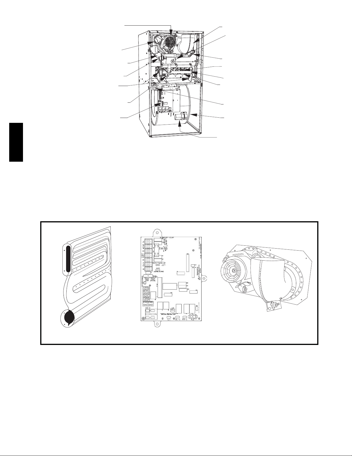
FURNACE COMPONENTS
INDUCER MOTOR
ASSEMBLY
PRESSURE
SWITCH
COLLECTOR
GAS VALVE
MANUAL RESET
LIMIT SWITCHES
FLUE
BOX
VENT ELBOW
MAIN LIMIT SWITCH
(BEHIND GAS VALVE)
DRAFT
SAFEGUARD
SWITCH
FLAME SENSOR
GAS MANIFOLD
GAS BURNER
HOT SURFACE
IGNITER
CONTROL
RATING PLATE
313AAV/JAV
NOT SHOWN
(LOCATED ON
BLOWER DOOR)
BLOWER DOOR
SAFETY SWITCH
BLOWER AND
MOTOR
CAPACITOR/POWER
CHOKE (WHERE USED)
NOTE: The 313AAV/JAV Furnaces are factory shipped for use with natural gas. These furnaces can be field-- converted for propane gas
with a factory--authorized and listed accessory conversion kit.
A02259
58DLA/DLX
A02169
A02169
A08063
A02170
REWOLB RECUDNIDRAOB LORTNOCREGNAHCXE TAEH
2
Page 3
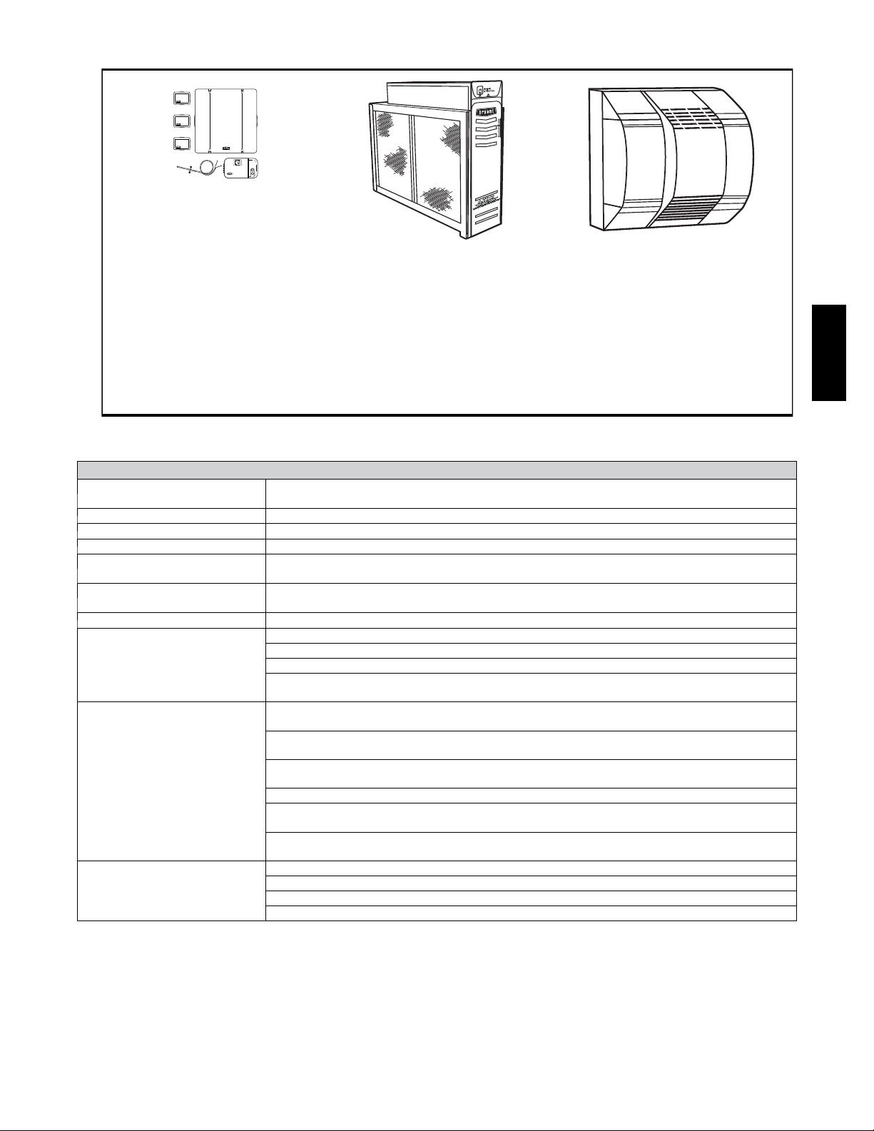
BRYANT ACCESSORIES
A97432
CONTROLS:
THERMOSTATS
AND ZONING
Available in programmable and
non-programmable models,
Bryant thermostats maintain a
constant, comfortable temperature level in the home.
For the ultimate in home comfort,
Bryant’s 2, 4, and 8-zone systems
allow temperature control of individual “zones” of the home. This is
accomplished through a series of
electronic dampers and
remote room sensors.
4-zone system is shown.
The
C04009
MECHANICAL
OR ELECTRONIC
AIR CLEANER
Cleans the air of smoke, dirt, and
many pollens commonly found.
Saves decorating and cleaning
expenses by keeping carpets,
furniture, and drapes cleaner.
Electronic air cleaner is shown.
MODEL HUMCCLFP
A01484
HUMIDIFIER
By adding moisture to winter-dry
air, a Bryant humidifier can often
improve comfort and keep
furniture, rugs, and draperies in
better condition. Moisturizing
household air also helps to retain
normal body heat and provides
comfort at lower temperatures.
313AAV/JAV
A08153
ACCESSORIES
ELECTRONIC AIR CLEANER
(EAC)
Model EACB
AIR PURIFIER Models GAPAAXBB1625, GAPAAXBB2025
MECHANICAL AIR CLEANER Models EZXCAB, FILCAB
HUMIDIFIER Model HUM
HEAT RECOVERY
VENTILATOR
ENERGY RECOVERY
VENTILATOR
Model HRV
Model ERV
UV LIGHTS Model UVL
F o r u s e w i t h 1 --- s p e e d A i r C o n d i t i o n e r --- d e g . F / C , A u t o C h a n g e o v e r --- T 6 --- N A C , T 2 --- N A C
T H E R M O S T A T --N O N --- P R O G R A M M A B L E
F o r u s e w i t h 1 --- s p e e d H e a t P u m p --- d e g . F / C , A u t o C h a n g e o v e r --- T 6 --- N H P, T 2 --- N H P *
F o r u s e w i t h 2 --- s p e e d A i r C o n d i t i o n e r --- d e g . F / C , A u t o C h a n g e o v e r --- T 6 --- N R H *
For use with multi--- use / stage configurations --- deg. F/C, Auto Changeover/Temperature and
H u m i d i t y C o n t r o l --- T 6 --- P R H
{
F o r u s e w i t h 1 --- s p e e d A i r C o n d i t i o n e r --- d e g . F / C , A u t o C h a n g e o v e r, 7 --- D a y P r o g r a m m a b l e --T 6 --- P A C
F o r u s e w i t h 1 --- s p e e d H e a t P u m p --- d e g . F / C , A u t o C h a n g e o v e r, 7 --- D a y P r o g r a m m a b l e --T6--- PHP*
T H E R M O S T A T --PROGRAMMABLE
F o r u s e w i t h 2 --- s p e e d A i r C o n d i t i o n e r --- d e g . F / C , A u t o C h a n g e o v e r, 7 --- D a y P r o g r a m m a b l e --T 6 --- P R H *
F o r u s e w i t h 1 --- s p e e d A i r C o n d i t i o n e r --- d e g . F / C , 5 --- 2 D a y P r o g r a m m a b l e --- T 6 --- P A C
F o r u s e w i t h m u l t i --- s t a g e a p p l i c a t i o n s --- d e g . F / C , A u t o C h a n g e o v e r , 7 --- D a y P r o g r a m m a b l e ---
T 2 --- P H P
}
F o r m u l t i --- u s e / s t a g e c o n f i g u r a t i o n s --- d e g . F / C , A u t o C h a n g e o v e r , 7 --- D a y P r o g r a m m a b l e /
Temperature and Humidity Control --- T6 ---PRH
{
Zone Perfect 3 --- Zone kit --- ZONEBB3ZAC01, ZONEBB3ZHP01
ZONING CONTROL
2 --- Z o n e P e r f e c t P l u s k i t / Te m p e r a t u r e a n d H u m i d i t y C o n t r o l --- Z O N E B B 2 K I T 0 1 --- B
4 --- Z o n e P e r f e c t P l u s k i t / Te m p e r a t u r e a n d H u m i d i t y C o n t r o l --- Z O N E B B 4 K I T 0 1 --- B
8 --- Z o n e P e r f e c t P l u s k i t / Te m p e r a t u r e a n d H u m i d i t y C o n t r o l --- Z O N E B B 8 K I T 0 1 --- B
*Model HP and 2S thermostat must be field converted to air conditioner operation.
{Thermidistatt Control can be configured for multiple use and staging. It must be configured for each specific application.
}Dual Fuel thermostat is used with furnace and heat pump application.
3
Page 4
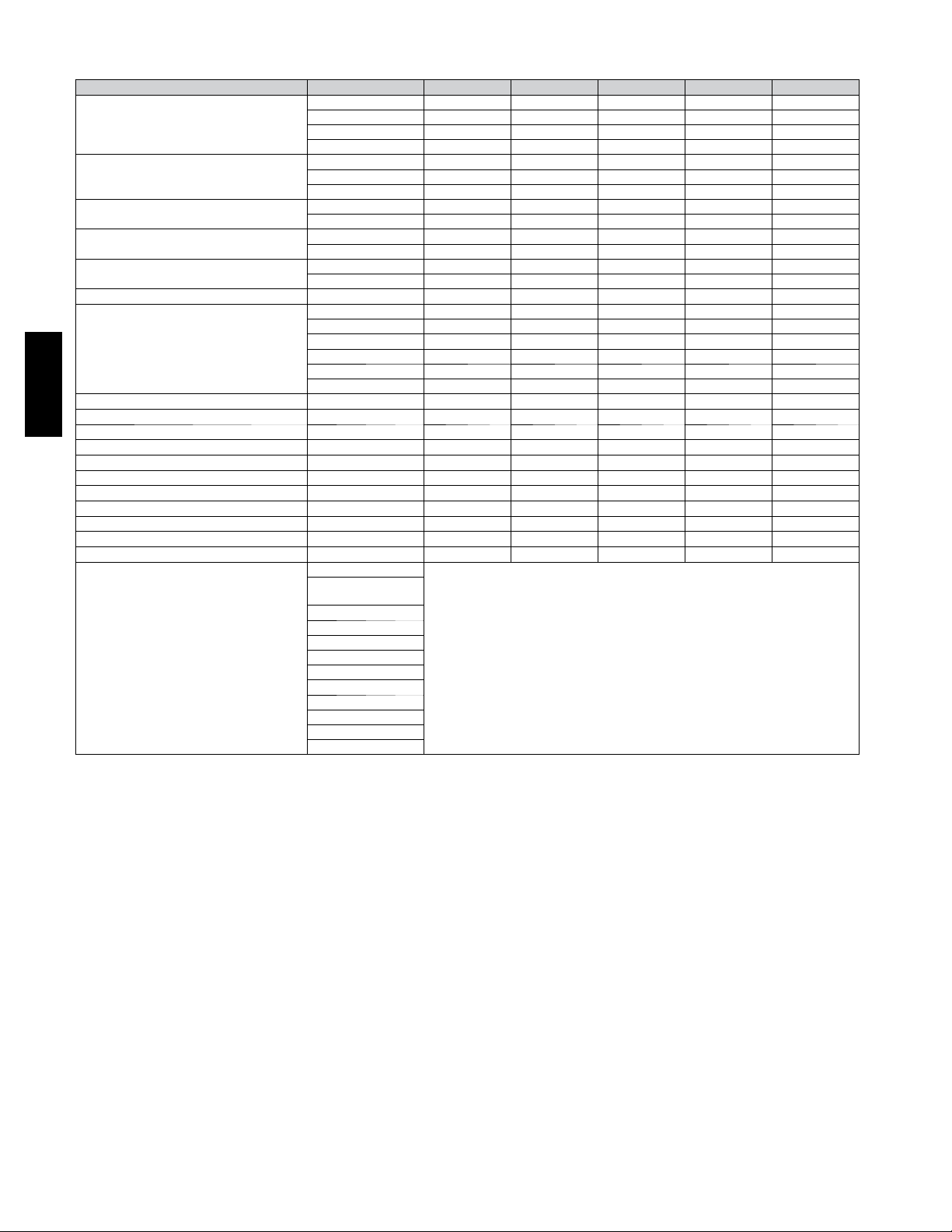
BRYANT ACCESSORIES
DESCRIPTION 313AAV/JAV PAR T NO. 024045 048070 048090 060110 060135
Cartridge Media Filter
EZ Flex Media Filter with End Caps
Replacement EZ Flex Filter Media
External Bottom Return
Filter Rack
External Side Return Filter Rack KGAFR0801SRE X X X X X
Unframed Filter 3/4--- in. (19 mm)
Flue Extension KGAFE0112UPH X X X X X
Combustible Floor Base KGASB0201ALL X X X X X
313AAV/JAV
Downflow Vent Guard KGAVG0101DFG X X X X X
Vent Extension Kit KGAVE0101DNH X X X X X
Chimney Adapter Kit KGACA02014FC X X X X
Chimney Adapter Kit KGACA02015FC X
N a t u r a l --- t o --- P r o p a n e C o n v e r s i o n K i t * KGANP4601ALL X X X X X
P r o p a n e --- t o --- N a t u r a l C o n v e r s i o n K i t * KGAPN3901ALL X X X X X
Label Kit KGALB0101KIT X X X X X
Air Leakage Kit (Qty 10) KGBAC0110DG K X X X X X
Air Leakage Kit (Qty 10) KGBAC0110DG K X X X X X
Gas Orifice Kit (Qty 50)
*Factory ---authorized and field --- installed. Gas conversion kits are CS A (AGA/CGA) recognized.
{Suitable f or Side Return Filter Rack (KGAFR0801SRE)
X --- A c c e s s o r y
S --- S t a n d a r d
FILBBCAR0016 X X
FILBBCAR0020 X X
FILBBCAR0024 X
EXPXXUNV0016 X X
EXPXXUNV0020 X X
EXPXXUNV0024 X
EXPXXFIL0016 X X
EXPXXFIL0020 X X
EXPXXFIL0024 X
KGAFR0401B14 X
KGAFR0501B17 X
KGAFR0601B21 X X
KGAFR0701B24 X
KGAWF1301UFR { S S
KGAWF1401UFR S S
KGAWF1501UFR S
KGAWF1306UFR { X X
KGAWF1406UFR X X
KGAWF1506UFR X
KGAHA0150N42
KGAHA0250N43
(factory supplied)
KGAHA0350N44
KGAHA0450N45
KGAHA0550N46
KGAHA1550N47
KGAHA1650N48
KGAHA0650P54
KGAHA0750P55
KGAHA0850P56
KGAHA5750125
KGAHA5750130
See Installation Instructions for model, altitude, and heat value usages.
4
Page 5

PHYSICAL DATA
UNIT SIZE 024045 048070 048090 060110 060135
OUTPUT CAPACITY
BTUH
( N o n --- w e a t h e r i z e d I C S )
INPUT BTUH
AFUE% N o n --- w e a t h e r i z e d I C S 80.0 80.0 80.0 80.0 80.0
SHIPPING WEIGHT LB. (KG) 104 (47) 126 (57) 140 (64) 152 (69) 163 (74)
CERTIFIED TEMP RISE RANGE ˚_F(_C)
CERTIFIED EXT STATIC
PRESSURE (IN. WC)
AIRFLOW CFM
LIMIT CONTROL SPST
HEATING BLOWER CONTROL Solid--- State Time Operation
BURNERS (Monoport) 2 3 4 5 6
GAS CONNECTION SIZE 1 / 2 --- i n . N P T
GAS VALVE(Redundant) Manufacturer W h i t e --- R o d g e r s
Minimum Inlet Pressure (in. wc) 4.5 (Natural Gas)
Maximum Inlet Pressure (in. wc) 13.6 (Natural Gas)
IGNITION DEVICE Hot Surface
*Gas input ratings are certified for elevations to 2000 ft. (610 M)*. In U S A, For elevations above 2000 ft. (610 M), reduce ra tings 4 percent for each 1000 ft. (305
M) above sea level. In Canada, derate the unit 10 percent for elevations 2000 to 4500 ft. (610 --- 1372 M) above sea l e vel. Refer to National Fuel Gas Code
NFPA 54/ANSI Z223.1---2006 Table F.1 (d) or furnace Installation Instructions.
{Capacity in accordance with U.S. Government DOE test procedures.
}Airflow shown is f o r bottom only return ---air supply. For air delivery above 1800 CFM, see Air Delivery Table for other options. A filter is required foreach
return---air supply. An airflow reduction of up to 7 percent may occur when using a Bryant 4 ---5/16 in. (110 mm) high efficiency media filter.
ICS - -- Isolated Combustion System
313JAV Upflow; all 313AAV 36,000 53,000 72,000 90,000 107,000
313JAV Downflow/Horizontal 34,000 51,000 69,000 86,000 102,000
313JAV Upflow; all 313AAV 44,000 66,000 88,000 110,000 132,000
313JAV Downflow/Horizontal 42,000 63,000 84,000 105,000 126,000
30--- 60
( 1 7 --- 3 3 )
Heating 0.10 0.12 0.15 0.20 0.20
Cooling 0.50 0.50 0.50 0.50 0.50
Heating 735 1230 1345 1890 1865
Cooling 1035 1460 1665 2040 2070
25--- 55
( 1 4 --- 3 1 )
35--- 65
( 1 9 --- 3 6 )
30--- 60
( 1 7 --- 3 3 )
40--- 70
( 2 2 --- 3 9 )
313AAV/JAV
BLOWER PERFORMANCE DATA
UNIT SIZE 024045 048070 048090 060110 060135
DIRECT---DRIVE MOTOR Hp (ECM --- 5 Speed) 1/2 3/4 3/4 1 1
MOTOR FULL LOAD AMPS 6.8 8.4 8.4 10.9 10.9
R P M ( N o m i n a l ) --- S P E E D S 1050--- 5 1050 --- 5 1050 --- 5 1050 -- -5 1050 --- 5
BLOWER WHEEL DIAMETER x WIDTHS --- IN (MM)
10 x 6
(254 x 152)
11 x 8
(279 x 203)
10X10
(254 x 254)
11 x 11
(279 x 279)
11 x 11
(279 x 279)
5
Page 6

SEE NOTES: 1,2,4,7,8,9
UPFLOW
A02058
SEE NOTES: 1,2,3,4,7,8,9
UPFLOW DOWNFLOW
A02059
SEE NOTES: 1,2,4,5,7,8,9
A02061
313AAV/JAV
SEE NOTES:1,2,3,4,5,7,8,9
DOWNFLOW
SEE NOTES: 1,2,3,4,7,8,9
DOWNFLOW
A02063A02060
SEE NOTES: 1,2,4,5,6,7,8,9
DOWNFLOW
Ven t i n g N ot e s
1. For common vent, vent connector sizing and vent material: United States, latest edition of the National Fuel Gas Code (NFGC),
NFPA54/ANSI Z223.1. In Canada, latest edition of the National Standards of Canada, Natural Gas and Propane Installation Code
(NSCNGPIC), CSA B149.1.
2. Immediately increase to 5--in. (127 mm) vent connector outside furnace casing when 5-- in. (127 mm) vent connector required, refer to
Note 1.
3. Side outlet vent for upflow and downflow installations must use Type B vent immediately after exiting the furnace, except when
KGAVG0101DFG is used in downflow position.
4. Type B vent where required, refer to Note 1.
5. 4--in. (102 mm) single wall vent must be used inside furnace casing and the KGAVG0101DFG Downflow Vent Guard Kit.
6. Accessory Downflow Vent Guard Kit, KGAVG0101DFG required in downflow installations with bottom vent configuration.
7. Chimney Adapter Kit required for exterior masonry chimney applications. Refer to Chimney Adapter Kit, KGACA02014FC and
KGACA02015FC for sizing and complete application details.
8. Secure vent connector to furnace elbow with (2) corrosion-- resistant sheet metal screws, space approximately 180_ apart.
9. Secure all other single wall vent connector joints with (3) corrosion--resistant screws spaced approximately 120_ apart. Secure Type B
vent connectors per vent connector manufacturer’s recommendations.
A02062
6
Page 7

SEE NOTES: 1,2,4,5,7,8,9
HORIZONTAL RIGHT
SEE NOTES: 1,2,4,5,7,8,9
A02068 A02070
HORIZONTAL RIGHT
SEE NOTES: 1,2,4,7,8,9
HORIZONTAL RIGHT
A02069
313AAV/JAV
SEE NOTES: 1,2,4,7,8,9
HORIZONTAL LEFT
A02064
SEE NOTES: 1,2,4,5,7,8,9
HORIZONTAL LEFT HORIZONTAL LEFT
A02066
SEE NOTES: 1,2,4,5,7,8,9
HORIZONTAL LEFT
SEE NOTES: 1,2,4,5,7,8,9
7
A02065
A02067
Page 8

AIR DELIVERY -- CFM (WITH FILTER)*
UNIT SIZE
024045
048070
048090
060110
313AAV/JAV
060135
*A filter is requ ired for each return ---air inlet. Airflow perfor mance included 3/4 --- in. (19 mm) washable filter media such as contained in factory ---authorized accessory filter rack. To determine airflow performance without this filter, assume an additional 0.1 in. wc available external static pressure.
--- --- Indicates unstable operating conditions.
RETURN--- AIR
SUPPLY
Bottom or
Side(s)
Bottom or
Side(s)
Bottom or
Side(s)
Bottom or
Side(s)
Bottom or
Side(s)
SPEED
5 1185 1145 1115 1075 1035 980 905 820 720 580
4 920 880 835 800 755 720 680 645 605 540
3 735 685 625 585 530 490 435 395 345 295
2 820 765 725 670 630 580 545 490 455 405
1 650 595 535 490 430 390 330 280 235 --- --5 1625 1585 1535 1495 1460 1415 1365 1295 1220 1125
4 1405 1360 1320 1280 1240 1195 1155 1115 1070 1030
3 1240 1200 1155 1110 1065 1020 975 935 895 850
2 1190 1140 1095 1050 1000 955 915 870 830 790
1 1035 985 930 885 835 785 745 695 650 600
5 1845 1800 1755 1710 1665 1595 1500 1400 1275 1105
4 1590 1545 1500 1455 1410 1365 1315 1270 1180 1000
3 1365 1320 1270 1215 1170 1125 1070 1025 955 900
2 1225 1160 1110 1060 1010 950 895 830 770 710
1 1100 1030 960 875 805 730 645 570 505 425
5 2255 2205 2150 2100 2040 1985 1920 1835 1735 1615
4 1600 1525 1465 1400 1335 1275 1210 1150 1080 1015
3 1945 1890 1830 1770 1715 1655 1600 1545 1480 1430
2 1420 1340 1280 1200 1140 1065 1005 925 865 790
1 1280 1205 1140 1055 990 910 840 760 695 630
5 2295 2240 2185 2125 2070 2005 1925 1805 1670 1545
4 1725 1660 1605 1545 1460 1395 1340 1285 1230 1170
3 1910 1865 1800 1745 1685 1610 1545 1485 1435 1380
2 1630 1575 1510 1435 1365 1300 1245 1185 1130 1065
1 1430 1355 1285 1200 1125 1075 1015 945 855 800
0.1 0.2 0.3 0.4 0.5 0.6 0.7 0.8 0.9 1
EXTERNAL STATIC PRESSURE (in. wc)
ELECTRICAL DATA
313AAV/
JAV UNIT
SIZE
024045 1 1 5 --- 60 --- 1 127 104 8.1 34 (10) 15 14
048070 1 1 5 --- 60 --- 1 127 104 9.5 29 (9) 15 14
048090 1 1 5 --- 60 --- 1 127 104 10.3 27 (8) 15 14
060110 1 1 5 --- 60 --- 1 127 104 13.1 34 (10) 20 12
060135 1 1 5 --- 60 --- 1 127 104 13.1 34 (10) 20 12
* Permissible limits of the voltage range at which the u nit operates satisfactorily.
{ T ime ---delay type is recommended.
}Length shown is as measured 1 way along wire path between unit and service panel for maximum 2 percent voltage drop.
V O L T S ---
H E R T Z ---
PHASE
OPERATING VOLTAGE
RANGE
*
Maximum Minimum
MAXIMUM
UNIT AMPS
MAXIMUM WIRE
LENGTH FT (M)
MAXIMUM FUSE
OR CKT BKR
}
AMPS
MINIMUM
{
WIRE GAGE
8
Page 9

DIMENSIONS
(
(664mm)
26-1/8"
(FLUE COLLAR)
5-15/16"
(22mm)
7/8" DI A
(135mm)
33-5/16"
(846mm)
1/2" (13 mm) DIA.
THERMOSTAT WIRE ENTRY
ACCESSORY
(733mm)
28-7/8"
(641mm)
25-1/4"
22-9/16"
(573mm)
JUNCTION BOX
LOCATION
3-15/16" (84mm)
LEFT HAND GAS
ENTRY
7/8" (22mm) DIA.
ACCESSORY
24-7/8"
(632mm)
F
A
D
13/16"
(21mm)
4-13/16"
(122mm)
8-9/16"
(217mm)
ALTERNA T E
JUNCTION BOX
LOCATIONS (TYP)
VENT OUTLE T
5 PLACES (TYP)
(140mm)
5-1/2"
2-7/16"
(62mm)
1-5/16"
(33mm)
1-1/8"
(29mm)
AIRFLOW
19"
(483mm)
OUTLE T
1/2" DIA. K.O.THERMOSTAT
WIRE ENTRY
7/8" DIA. K.O. WIRE ENTRY
(22mm)
(22mm)
(13mm)
1-3/4" DIA.RIGHT HAND
GAS ENTRY
7/8" DIA. ACCESSORY
(44mm)
13/16"
(21mm)
11/16"
(17mm)
14-7/8"
(378mm)
7-3/4"
(197mm)
9-5/8"
(244mm)
11-1/2"
(292mm)
11/16"
(17mm)
(549mm)
21-5/8"
BOTTOM INLE T
24"
CASING
610mm)
1-11/16"
(43mm)
5-1/2"
(140mm)
E
11/16"
(17mm)
3-3/4"
(95mm)
1-1/2"
(560mm)
22-1/16"
SIDE INLE T
(38mm)
(25mm)
1. Two additional 7/8--in. (22 mm) dia. knockouts are located in the top plate.
2. Minimu m retur n --air openings at furnace, based on metal duct. If flex duct is used, see flex duct manufacturer’s recommendations for equivalent diameters.
3. Minimum retur n --air opening at furnace.
a. For 800 CFM--16--in. (406 mm) round or 14--1/2 x 12 --in. (368 x 305 mm) rectangle.
b. For 1200 CFM--20--in. (508 mm) round or 14--1/2 x 19 --1/3 in. (368 x 491 mm)rectangle.
c. For 1600 CFM--22--in. (559 mm) round or 14--1/2 x 22 --1/16--in. (368 x 560 mm) rectangle.
d. For airflow requirements above 1800 CFM, see Air Delivery table in Product Data literature for specific use of single side inlets. The use of both side inlets, a
combination of 1 side and the bottom, or the bottom of single side inlets. The use of both side inlets, a combination of one side and the bottom, or the bottom only
will ensure adequate return air openings for airflow requirements above 1800 CFM.
313AAV/JAV
UNIT SIZE
A
CABINET
WIDTH
IN (MM)
D
SUPPLY WIDTH
IN (MM)
E
BOTTOM
RETURN WIDTH
IN (MM)
F
TOP VENT
OUTLET
IN (MM)
VENT
CONNECTION
SIZE
(see Notes 1 & 2)
024045 14--- 3/16 (360) 12--- 9/16 (319) 12 --- 11/16 (322) 9--- 5/16 (237) 4 16 (406)
048070 17--- 1/2 (445) 15--- 7/8 (403) 16--- 1/8 (410) 11 --- 9/16 (294) 4 16 (406)
048090 21 (533) 19--- 3/8 (492) 19--- 1/2 (495) 13 --- 5/16 (338) 4 20 (508)
060110 21 (533) 19--- 3/8 (492) 19--- 1/2 (495) 13 --- 5/16 (338) 4 20 (508)
060135 24--- 1/2 (622) 22--- 7/8 (581) 23 (584) 15--- 1/16 (383) 4(Note1) 24 (610)
1. 135 size furnaces require 5 ---in. (127 mm) vents. Use a 4---5 in. (102 --- 127 mm) vent adaptor between furnace and vent stack.
2. See installation instructions for complete installation requirements.
1-1/4"
(32mm)
1"
MEDIA CABINET
SIZE
IN (MM)
313AAV/JAV
A04037
9
Page 10

313AAV/JAV
A08471
ISO 9001:2000
r
o
p
C
o
r
r
e
a
I
S
G
E
N
D
C
E
D
E
R
®
I
T
F
I
EFFICIENCY
RATING
CERTIFIED
CERTIFIED
r
r
a
C
R
E
G
I
S
I
S
O
i
REGISTERED
9
REGISTERED QUALITY SYSTEM
5
/
23
8
"
(600mm)
3
/
8
23
"
(600mm)
t
i
o
n
M
¨
R
I
F
T
E
D
R
E
3
8
8
0
2
0
A
1
#
MEETS DOE RESIDENTIAL CONSERVATION
SERVICES PROGRAM STANDARDS.
Before purchasing this appliance, read important
energy cost and efficiency information available
from your retailer.
5
/
8
"
25
(651mm)
1
(651mm)
/
2
24
"
With Flanges Bent Out
1
(587mm)
/
8
"
23
Opening
Furnace Side
3
/
23
4
Centerline Screw Slots
"
(603mm)
3
/
5
4
"
(146mm)
A
B
10
Media/
Filter Cabinet
(406mm)
16"/
(508mm)
20"/
(610mm)
24"/
Duct Side
ABC
1
/
17"/ 16
(432mm)
21"/ 20
(533mm)
25"/ 24
(635mm)
(413mm)
(514mm)
(616mm)
15"/
4"/
(381mm)
1
/
19"/
4"/
(483mm)
1
/
23"/
4"/
(584mm)
with Flanges Bent In
C Opening
A00444
Page 11

TYPICAL WIRING SCHEMATIC
NOTE 2
FIVE WIRE
THREE-WIRE
HEATING-ONLY
BLOWER DOOR SWITCH
BLK
WHT
GND
115-V FIELD-
SUPPLIED
DISCONNECT
BLK
WHT
GND
AUXILIARY
J-BOX
FURNACE
W
C
R
O
N
T
G
R
O
COM
L
Y/Y2
24-V
TERMINAL
BLOCK
FIELD 24-V WIRING
FIELD 115-, 208/230-, 460-V WIRING
FACTORY 24-V WIRING
FACTORY 115-V WIRING
WCR GY
THERMOSTAT
TERMINALS
FIELD-SUPPLIED
DISCONNECT
208/230- OR
460-V
THREE
PHASE
208/230-V
SINGLE
PHASE
NOTE 1
CONDENSING
GND
UNIT
TWO
WIRE
NOTES: Connect Y-terminal in furnace as shown for proper blower operation.
1.
2.
Some thermostats require a "C" terminal connection as shown.
3.
If any of the original wire, as supplied, must be replaced, use
same type or equivalent wire.
313AAV/JAV
A99440
TYPICAL INSTALLATION
CONDENSING
UNIT
AIRFLOW
ELECTRONIC
AIR CLEANER
HUMIDIFIER
GAS-FIRED
WATER HEATER
A08177
11
Page 12

GUIDE SPECIFICATIONS
Gas Furnace
313AAV/JAV
GENERAL
System Description
Furnish a _________________ fixed capacity gas-- fired furnace
for use with natural gas or propane (factory authorized conversion
kit required for propane); furnish cold air return plenum; furnish
external medial cabinet for use with accessory media filter or
standard filter.
Quality Assurance
Unit will be designed, tested and constructed to the current ANSI Z
21.47/CSA 2.3 design standard for gas-- fired central furnaces.
Unit will be 3rd party certified by CSA to the current ANSI Z
21.47/CSA 2.3 design standard for gas-- fired central furnaces.
Unit will carry the CSA Blue Star® and Blue Flame® labels.
Unit efficiency testing will be performed per the current DOE test
procedure as listed in the Federal Register.
Unit will be certified for capacity and efficiency and listed in the
latest GAMA Consumer’s Directory of Certified Efficiency
313AAV/JAV
Ratings.
Unit will carry the current Federal Trade Commission Energy
Guide efficiency label.
Delivery, Storage and Handling
Unit shall be shipped as single package only and is stored and
handled per unit manufacturer’s recommendations.
Warranty (for inclusion by specifying engineer)
U.S. and Canada only. Warranty certificate available upon request.
PRODUCTS
Equipment
Components shall include: slow--opening gas valve to reduce
ignition noise, regulate gas flow, with electric switch gas shut--off;
flame proving sensor, hot surface igniter, pressure switch assembly;
flame rollout switch, blower and inducer assembly, 40va
transformer; low--voltage (heating) (heating/ cooling) thermostat.
Blower Wheel and Blower Motor
Galvanized blower wheel shall be centrifugal type, statically and
dynamically balanced. Blower motor of ECM type shall be
permanently lubricated with sealed bearings, of _______hp, and
shall be multiple--speed direct drive. Blower motor shall be soft
mounted to the blower scroll to reduce vibration transmission.
Filters
Furnace may have reusable--type filters. Filter shall be _______ in
(x) _______in. (mm).An accessory high efficiency Media Filter is
available as an option. _______________ Media Filter.
Casing
Casing shall be of .030 in. (.76 mm) thickness minimum,
pre--painted galvanized steel.
Inducer Motor
Inducer motor shall be soft mounted to reduce vibration
transmission.
Draft Safeguard Switch
Draft Safeguard Switch (blocked vent safeguard) shall be factory
installed to reduce the possibility of vent gas infiltration due to a
blocked or restricted vent pipe.
Heat Exchangers
Heat exchangers shall be a 4--Pass 20 gage aluminized steel of
fold--and--crimp sectional design when applied operating under
negative pressure.
Controls
Control shall include a micro--processor based integrated electronic
control board with at least 11 service troubleshooting codes
displayed via diagnostic flashing LED light on the control, a
self--test feature that checks all major functions of the furnace
within one minute, and a replaceable automotive--type circuit
protection fuse. Multiple operational settings available including,
separate blower speeds for heating, cooling and continuous fan.
Continuous fan speed may be adjusted from the thermostat.
Features will also include temporary reduced airflow in the cooling
mode for improved dehumidification when a Thermidistatt
Control is selected as the thermostat.
Operating Characteristics
Heating Capacity shall be ________ Btuh input; ________ Btuh
output capacity.
Fuel Gas Efficiency shall be 80% AFUE.
Air delivery shall be ___________ CFM minimum at 0.50 in. wc
external static pressure.
Dimensions shall be: depth __________ in.; width _________ in;
height_________in. (mm) (casing only). Height shall
be_________in. (mm) with A/C coil and _____________in. (mm)
overall with plenum.
Electrical Requirements
Electrical supply shall be 115 volts, 60 Hz, single--phase (nominal).
Minimum wire size shall be_________AWG; maximum fuse size
or circuit breaker shall be __________Amps.
Special Features
Refer to section of the product data sheet identifying accessories
and descriptions for specific features and available enhancements.
Bryant Heating & Cooling Systems D 7310 W. Morris St. D Indianapolis, IN 46231 Printed in U.S.A. Edition Date: 3/09
Manufacturer reserves the right to discontinue, or change at any time, specifications or designs without notice and without incurring obligations.
12
Catalog No. PDS313AAV--- 0 4
Replaces: PDS313AAV---03
 Loading...