

Bryant 140, 140E, 312AAV, 312JAV Installation, Start-up, Operating And Service And Maintenance Instructions
312AAV/JAV
2--STAGE DELUXE, INDUCED COMBUSTION
4--WAY MULTIPOISE GAS FURNACE
Installation, Start--up, Operating and
Service and Maintenance Instructions
Series 140/E
SAFETY CONSIDERATIONS 2........................
INTRODUCTION 3..................................
CODES AND STANDARDS 5..........................
Safety 5...........................................
General Installation 5................................
Combustion and Ventilation Air 5......................
Duct Systems 5.....................................
Acoustical Lining and Fibrous Glass Duct 5...............
Gas Piping and Gas Pipe Pressure Testing 5...............
Electrical Connections 5..............................
Venting 5.........................................
ELECTROSTATIC DISCHARGE (ESD) PRECAUTIONS
PROCEDURE 5.....................................
LOCATION 6.......................................
AIR FOR COMBUSTION AND VENTILATION 7.........
INSTALLATION 10..................................
UPFLOW INSTALLATION 10......................
DOWNFLOW INSTALLATION 11...................
HORIZONTAL INSTALLATION 11..................
FILTER ARRANGEMENT 15.......................
AIR DUCTS 15...................................
GAS PIPING 17..................................
ELECTRICAL CONNECTIONS 21..................
VENTING 26....................................
START--UP, ADJUSTMENT, AND SAFETY CHECK 33.....
General 33........................................
Start--Up Procedures 34..............................
Adjustments 34.....................................
Check Safety Controls 39.............................
Checklist 39.......................................
SERVICE AND MAINTENANCE PROCEDURES 44.....
Introduction 44...................................
Care and Maintenance 45...........................
Sequenceof Operation 49...........................
Wiring Diagrams 52...............................
Troubleshooting 52................................
Accessory List 55.................................
PARTS REPLACEMENT INFORMATION GUIDE 56.....
I
G
S
E
N
D
C
E
E
R
I
T
F
I
Use of the AHRI Certified TM Mark indicates a
manufacturer’s participation in the program. For
verification of certification for individual products,
go to www.ahridirectory.org.
ISO 9001:2000
D
REGISTERED
Always Ask For
NOTE: Read the entire instruction manual before starting the
installation.
Portions of the text and tables are reprinted from NFPA 54/ANSI
Z223.1--2009E, with permission of National Fire Protection
Association, Quincy, MA 02269 and American Gas Association,
Washington DC 20001. This reprinted material is not the
complete and official position of the NFPA or ANSI on the
referenced subject, which is represented only by the standard in
its entirety.
A
B
[736.9]
29
Ø7/8
[22.2]
ACCESSORY
5 15/16
[150.7]
28.39
[721.2]
Ø7/8
[22.2]
ACCESSORY
14 7/8
[337.3]
(BOTH SIDES)
Ø7/8
[22.2]
ACCESSORY
Ø7/8
[22.2]
ACCESSORY
Ø1 3/4
[44.5]
GAS ENTRY
Ø1/2
[12.7]
THERMOSTAT WIRE ENTRY
22 1/16
[560]
SIDE INLET
(BOTH SIDES)
11 7/16
[290.7]
9 11/16
[245.4]
[197.8]
7 13/16
Ø7/8
[22.2]
J.BOX PROVISION
Ø7/8
[22.2]
JUNCTION BOX
LOCATION
Ø1 3/4
[44.5]
GAS ENTRY
1 15/16
[49.2]
1
[25.4]
1 1/4
[31.8]
29 9/16
[750.7]
1 15/16
[49.2]
5 5/8
[143.3]
5 7/16
[138.5]
6 13/16
[172.3]
Ø1/2
[12.7]
THERMOSTAT WIRE ENTRY
19
[481.7]
OUTLET
D
21.6
[549.5]
BOTTOM INLET
C
33 1/4
[843.9]
9 9/16
[243.3]
3/4
[19.1]
5 7/8
[148.5]
3 7/16
[86.8]
9 7/8
[250.7]
27 3/4
[704.7]
2 5/16
[59]
FRONT OF CASING
TOP OF CASING
4 13/16
[122.2]
27 3/4
[704.7]
5 7/8
[148.5]
8 5/8
[219]
5 1/2
[140.3]
8 7/16
[213.5]
FRONT OF CASING
TOP OF CASING
6.1
[155.7]
2 1/16
[51.6]
5.1
5.1
[130.5]
1.7
[43.5]
Ø7/8
[22.2]
ACCESSORY (2)
AIR FLOW
AIR FLOW
BOTTOM RETURN
WIDTH
AIR FLOW
KNOCK OUTS FOR
VENTING(5
PLACES)
[130.5]
2 1/16
[51.6]
1.7
[43.5]
Ø7/8
[22.2]
ACCESSORY (2)
FRONT OF CASING
8 5/8
[219]
6 13/16
FRONT OF CASING
1 15/16
[49.2]
5 15/16
[150.7]
5 1/2
[140.3]
8 7/16
[213.5]
9 7/8
[250.7]
27 3/4
[704.7]
33 1/4
[843.9]
312AAV
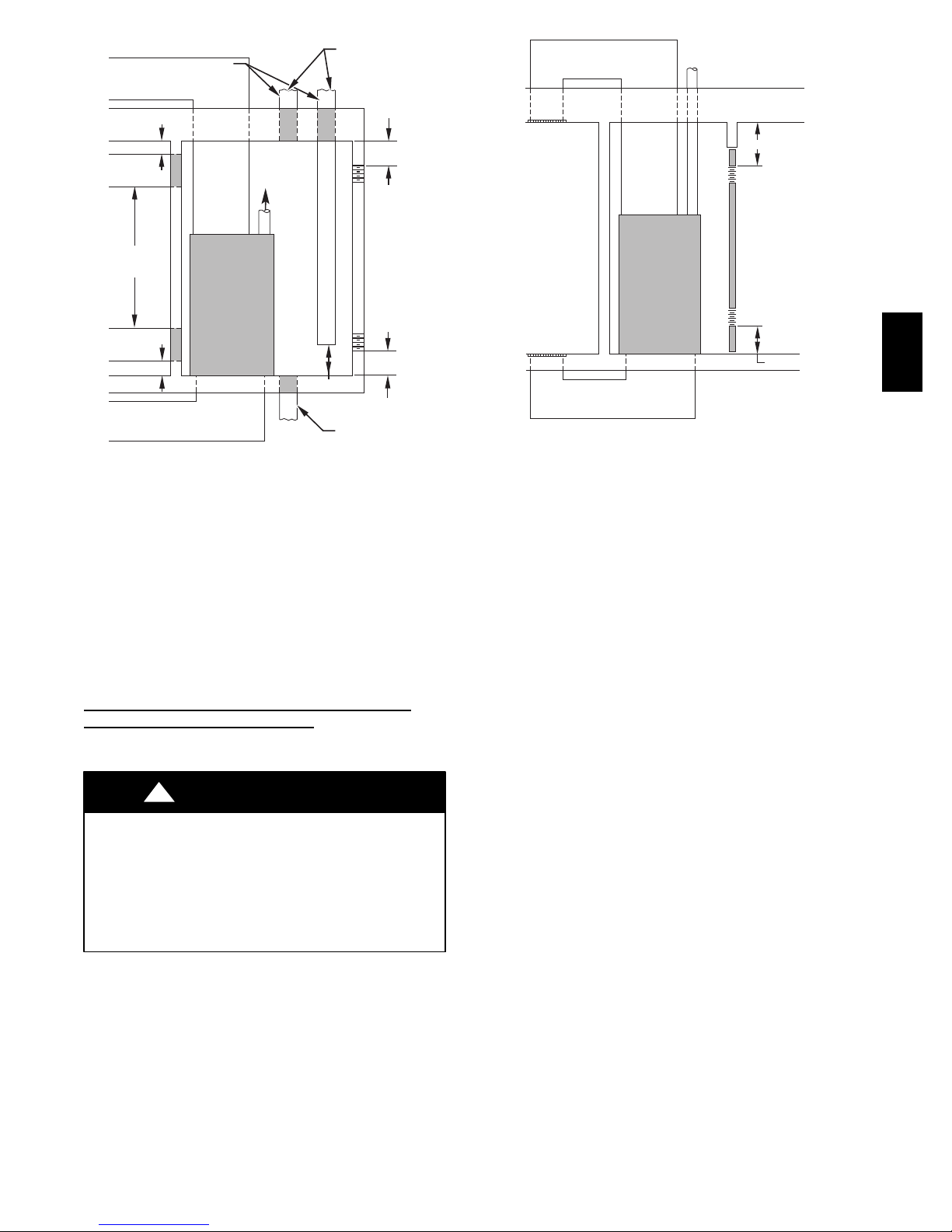
NOTES:
1. Two additional 7/8 --- in. (22 mm) diameter holes are located in the top plate.
2. Minimum return ---air openings at furnace, based on metal duct. If flex duct is used, see flex duct manufacturer’s recommendations for equivalent diameters.
AIR FLOW
ACCESSORY
THERMOSTAT WIRE ENTRY
ACCESSORY
21.6
[549.5]
BOTTOM INLET
28.39
[721.2]
29
[736.9]
Ø7/8
[22.2]
Ø7/8
[22.2]
Ø1/2
[12.7]
6.1
[155.7]
3 7/16
[86.8]
5 7/8
[148.5]
2 5/16
[59]
TOP OF CASING
Ø7/8
[22.2]
JUNCTION BOX
LOCATION
Ø1 3/4
[44.5]
GAS ENTRY
AIR FLOW
A
BOTTOM RETURN
WIDTH
TOP OF CASING
3/4
[19.1]
29 9/16
[750.7]
27 3/4
[704.7]
KNOCK OUTS FOR
VENTING(5
PLACES)
[148.5]
5 7/16
[138.5]
4 13/16
[122.2]
9 9/16
[243.3]
J.BOX PROVISION
ACCESSORY
5 7/8
[172.3]
[143.3]
1 15/16
[49.2]
Ø7/8
[22.2]
Ø7/8
[22.2]
5 5/8
AIR FLOW
19
[481.7]
OUTLET
Ø1/2
[12.7]
THERMOSTAT WIRE ENTRY
Ø1 3/4
[44.5]
GAS ENTRY
Ø7/8
[22.2]
ACCESSORY
22 1/16
[560]
SIDE INLET
(BOTH SIDES)
a. For 800 CFM---16 ---in. (406 mm) round or 14 1/2 x 12---in. (368 x 305 mm) rectangle.
b. For 1200 CFM---20 ---in. (508 mm) round or 14 1/ 2 x 19 1/2 ---in. (368 x 495 mm) rectangle.
c. For 1600 CFM---22 ---in. (559 mm) round or 14 1/ 2 x 22 1/16 ---in. (368 x 560mm) rectangle.
d. For airfl ow requirements above 1800 C FM, see Air Delivery table in Product Data literature for specific use of single side inlets. The use of both sideinlets,
a combination of 1 side and the bottom, or the bottom only will ensure adequate return air openings f o r airflow requirements above 1800 CFM.
7 13/16
[197.8]
14 7/8
[337.3]
(BOTH SIDES)
[25.4]
9 11/16
[245.4]
1 1/4
[31.8]
A10290
11 7/16
[290.7]
A
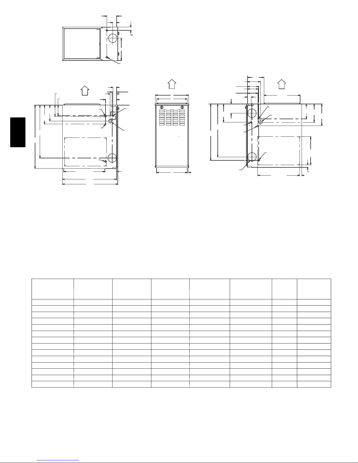
FURNACE SIZE
045 ---08/024045 14--- 3/16 (360) 12---9/16 (319) 9--- 5/16 (237) 12---11/16 (322) 4 (102) 104 (47) 16 (406)
045 ---12/036045 14--- 3/16 (360) 12---9/16 (319) 9--- 5/16 (237) 12---11/16 (322) 4 (102) 107 (49) 16 (406)
070 ---08/024070 14--- 3/16 (360) 12---9/16 (319) 9--- 5/16 (237) 12---11/16 (322) 4 (102) 111 (50) 16 (406)
070 ---12/036070 14--- 3/16 (360) 12---9/16 (319) 9--- 5/16 (237) 12---11/16 (322) 4 (102) 115 (52) 16 (406)
070 ---16/048070 17---1/2 (445) 15--- 7/8 (403) 11--- 9/16 (294) 16 (406) 4 (102) 126 (57) 16 (406)
090 ---14/042090 17---1/2 (445) 15--- 7/8 (403) 11--- 9/16 (294) 16 (406) 4 (102) 127 (58) 16 (406)
090 ---16/048090 21 (533) 19 --- 3/8 (492) 13--- 5/16 (338) 19--- 1/2 (495) 4 (102) 140 (64) 20 (508)
090 ---20/060090 21 (533) 19 --- 3/8 (492) 13--- 5/16 (338) 19--- 1/2 (495) 4 (102) 146 (66) 20 (508)
CABINET
WIDTH
OUTLET WIDTH
110 ---12/036110 17---1/2 (445) 15--- 7/8 (403) 11--- 9/16 (294) 16 (406) 4 (102) 135 (61) 16 (406)
110 ---16/048110 21 (533) 19 --- 3/8 (492) 13--- 5/16 (338) 19--- 1/2 (495) 4 (102) 146 (66) 20 (508)
110 ---22/066110 21 (533) 19 --- 3/8 (492) 13--- 5/16 (338) 19--- 1/2 (495) 4 (102) 152 (69) 20 (508)
135 ---16/048135 21 (533) 19 --- 3/8 (492) 13--- 5/16 (338) 19--- 1/2 (495) 4 (102){ 149 (68) 20 (508)
135 ---22/066135 24---1/2 (622) 22--- 7/8 (581) 15--- 1/16 (383) 23 (584) 4 (102){ 163 (74) 24 (610)
155 ---20/060155 24---1/2 (622) 22--- 7/8 (581) 15--- 1/16 (383) 23 (584) 4 (102){ 170 (77) 24 (610)
*135 and 155 size furnaces require a 5 or 6---in. (127 or 152 mm) vent. Use a vent adapter between furnace and vent stack. See Installation Instructions for
complete installation requirements.
Fig. 1 -- Dimensional Drawing
Table 1 – Dimensions -- In. (mm)
B
C
TOP &
BOTTOM FLUE
COLLAR
INLET WIDTH
2
D
BOTTOM
VENT
CONNECTION
SIZE
SHIP WT
LB (KG)
ACCESSORY
FILTER MEDIA
CABINET
SAFETY CONSIDERATIONS
!
WARNING
FIRE, EXPLOSION, ELECTRICAL SHOCK, AND
CARBON MONOXIDE POISONING HAZARD
Failure to follow this warning could result in dangerous
operation, serious injury, death, or property damage.
Improper installation, adjustment, alteration, service,
maintenance, or use could cause carbon monoxide
poisoning, explosion, fire, electrical shock, or other
conditions which may cause personal injury or property
damage. Consult a qualified service agency, local gas
supplier, or your distributor or branch for information or
assistance. The qualified service agency must use only
factory--authorized and listed kits or accessories when
modifying this product.
!
FURNACE RELIABILITY HAZARD
Improper installation or misapplication of furnace may
require excessive servicing or cause premature component
failure.
Application of this furnace should be indoors with special
attention given to vent sizing and material, gas input rate,
air temperature rise, unit leveling, and unit sizing.
!
CUT HAZARD
Failure to follow this caution may result in personal injury.
Sheet metal parts may have sharp edges or burrs. Use care
and wear appropriate protective clothing, safety glasses and
gloves when handling parts, and servicing furnaces.
Improper installation, adjustment, alteration, service,
maintenance, or use can cause explosion, fire, electrical shock, or
other conditions which may cause death, personal injury, or
property damage. Consult a qualified installer, service agency, or
your distributor or branch for information or assistance. The
qualified installer or agency must use factory--authorized kits or
accessories when modifying this product. Refer to the individual
instructions packaged with the kits or accessories when installing.
Follow all safety codes. Wear safety glasses, protective clothing,
and work gloves. Have a fire extinguisher available. Read these
instructions thoroughly and follow all warnings or cautions
include in literature and attached to the unit. Consult local
building codes, the current editions of the National Fuel Gas
Code (NFGC) NFPA 54/ANSI Z223.1 and the National
Electrical Code (NEC) NFPA 70.
Recognize safety information. This is the safety--alert symbol
When you see this symbol on the unit and in instructions or
manuals, be alert to the potential for personal injury.
Understand the signal words DANGER, WARNING,and
CAUTION. These words are used with the safety--alert symbol.
DANGER identifies the most serious hazards which will result in
severe personal injury or death. WARNING signifies hazards
which could result in personal injury or death. CAUTION is
used to identify unsafe practices which may result in minor
personal injury or product and property damage. NOTE is used
to highlight suggestions which will result in enhanced
installation, reliability, or operation.
CAUTION
CAUTION
.
product and property damage. NOTE is used to highlight
suggestions which will result in enhanced installation, reliability,
or operation.
1. Use only with type of gas approved for this furnace. Refer
to the furnace rating plate.
2. Install this furnace only in a location and position as specified in the “Location” section of these instructions.
3. Provide adequate combustion and ventilation air to the
furnace space as specified in “Air for Combustion and
Ventilation” section.
4. Combustion products must be discharged outdoors. Connect this furnace to an approved vent system only, as specified in the “Venting” section of these instructions.
5. Never test for gas leaks with an open flame. Use a commercially available soap solution made specifically for the
detection of leaks to check all connections, as specified in
the “Gas Piping” section.
6. Always install furnace to operate within the furnace’s intended temperature--rise range with a duct system which
has an external static pressure within the allowable range,
as specified in the “Start--Up, Adjustments, and Safety
Check” section. See furnace rating plate.
7. When a furnace is installed so that supply ducts carry air
circulated by the furnace to areas outside the space containing the furnace, the return air shall also be handled by
duct(s) sealed to the furnace casing and terminating outside the space containing the furnace. See “Air Ducts” section.
8. A gas--fired furnace for installation in a residential garage
must be installed as specified in the warning box in the
“Location” section.
9. The furnace may be used for construction heat provided
that the furnace installation and operation complies with
the first CAUTION in the LOCATION section of these instructions.
10. These Multipoise Gas--Fired Furnaces are CSA (formerly
A.G.A. and C.G.A.) design--certified for use with natural
and propane gases (see furnace rating plate) and for installation in alcoves, attics, basements, closets, utility rooms,
crawlspaces, and garages. The furnace is factory--shipped
for use with natural gas. A CSA (A.G.A. and C.G.A.) listed accessory gas conversion kit is required to convert furnace for use with propane gas.
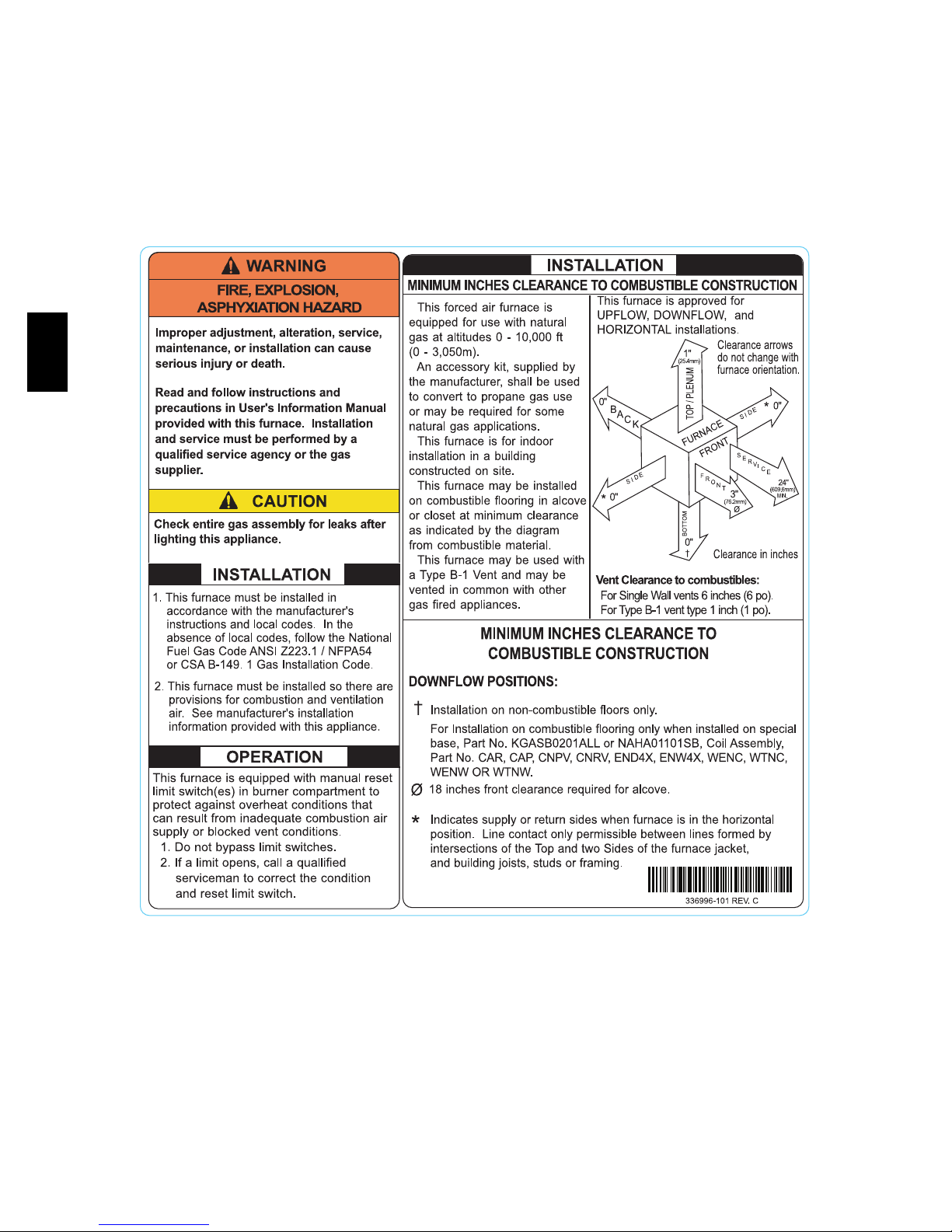
11. See Fig. 2 for required clearances to combustible construction.
12. Maintain a 1--in. (25 mm) clearance from combustible materials to supply air ductwork for a distance of 36 inches
(914 mm) horizontally from the furnace. See NFPA 90B
or local code for further requirements.
13. These furnaces SHALL NOT be installed directly on carpeting, tile, or any other combustible material other than
wood flooring. In downflow installations, factory accessory floor base MUST be used when installed on combustible materials and wood flooring. Special base is not required when this furnace is installed on manufacturer’s
Coil Assembly Part No. CAR, CAP, CNRV, CNPV or
when Coil Box Part No. KCAKC is used. See Fig. 2 for
clearance to combustible construction information.
INTRODUCTION
The Series 140/E 4--way multipoise Category I fan--assisted
furnace is CSA (formerly A.G.A. and C.G.A.) design--certified. A
Category I fan--assisted furnace is an appliance equipped with an
integral mechanical means to either draw or force products of
combustion through the combustion chamber and/or heat
exchanger. The furnace is factory--shipped for use with natural
312AAV
3
gas. This furnace is not approved for installation in mobile
homes, recreational vehicles, or outdoors.
These furnaces shall not be installed directly on carpeting, tile, or
any other combustible material other than wood flooring. For
downflow installations, a factory accessory floor base must be
used when installed on combustible materials and wood flooring.
This special base is not required when this furnace is installed on
the manufacturer’s coil assembly, or when the manufacturer’s coil
box is used. See Fig. 2 for clearance to combustible material
information.
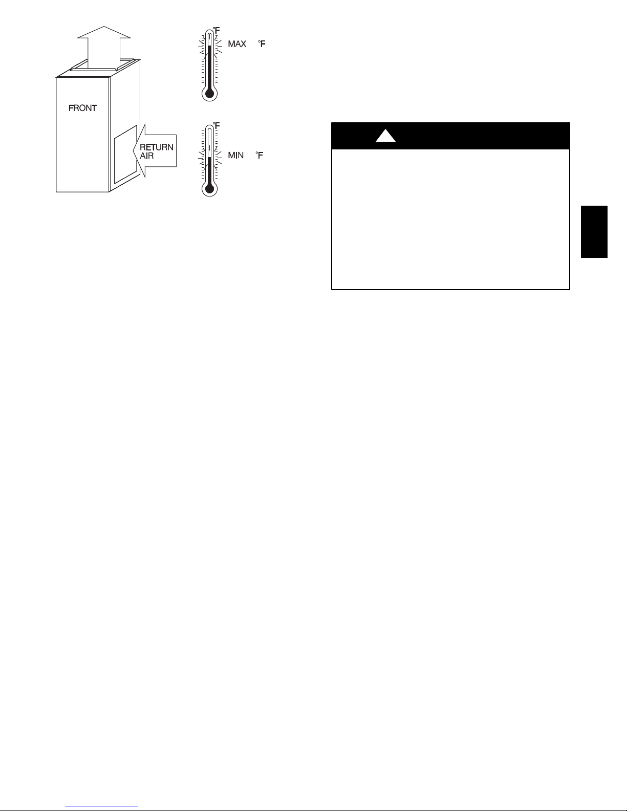
This furnace is designed for minimum continuous return--air
temperature of 60_F(16_C) db or intermittent operation down to
312AAV
55_F(13_C) db such as when used with a night setback
thermostat. Return--air temperature must not exceed 80_F(27_C)
db. Failure to follow these return--air temperature limits may
affect reliability of heat exchangers, motors, and controls. (See
Fig. 3.)
For accessory installation details, refer to the applicable
instruction literature.
NOTE: Remove all shipping brackets and materials before
operating the furnace.
A10269
Fig. 2 -- Clearances to Combustibles
4
80 / 27 C
60
/ 16 C
A06745
Fig. 3 -- Return Air Temperature
CODES AND STANDARDS
Follow all national and local codes and standards in addition
to these instructions. The installation must comply with
regulations of the serving gas supplier, local building, heating,
plumbing, and other codes. In absence of local codes, the
installation must comply with the national codes listed below and
all authorities having jurisdiction.
In the United States, follow all codes and standards for the
following:
Step 1 — Safety
National Fuel Gas Code (NFGC) NFPA 54--2009/ANSI
Z223.1--2009 and the Installation Standards, Warm Air Heating
and Air Conditioning Systems ANSI/NFPA 90B
Step 2 — General Installation
Current edition of the NFGC and the NFPA 90B. For copies,
contact the National Fire Protection Association Inc.,
Batterymarch Park, Quincy, MA 02269; (www.NFPA.org) or for
only the NFGC, contact the American Gas Association, 400 N.
Capitol Street, N.W., Washington DC 20001 (www.AGA.org.)
Step 3 — Combustion and Ventilation Air
Section 9.3 of the NFGC, NFPA 54/ ANSI Z223.1--2009 Air for
Combustion and Ventilation
Step 4 — Duct Systems
Air Conditioning Contractors Association (ACCA) Manual D,
Sheet Metal and Air Conditioning Contractors National
Association (SMACNA), or American Society of Heating,
Refrigeration, and Air Conditioning Engineers (ASHRAE) 2001
Fundamentals Handbook Chapter 34 or 2000 HVAC Systems
and Equipment Handbook Chapters 9 and 16.
Step 5 — Acoustical Lining and Fibrous Glass Duct
Current edition of SMACNA and NFPA 90B as tested by UL
Standard 181 for Class I Rigid Air Ducts
Step 6 — Gas Piping and Gas Pipe Pressure Testing
NFPA 54 / ANSI Z223.1--2009; chapters 5, 6, 7, and 8 and
National Plumbing Codes
Step 7 — Electrical Connections
National Electrical Code (NEC) ANSI/NFPA 70--2008
Step 8 — Venting
NFGC; NFPA 54 / ANSI Z223.1--2009 chapters 12 and 13
ELECTROSTATIC DISCHARGE (ESD)
PRECAUTIONS PROCEDURE
!
CAUTION
FURNACE RELIABILITY HAZARD
Improper installation or service of furnace may cause
premature furnace component failure.
Electrostatic discharge can affect electronic components.
Follow the Electrostatic Discharge Precautions Procedure
listed below during furnace installation and servicing to
protect the furnace electronic control. Precautions will
prevent electrostatic discharges from personnel and hand
tools which are held during the procedure. These
precautions will help to avoid exposing the control to
electrostatic discharge by putting the furnace, the control,
and the person at the same electrostatic potential.
1. Disconnect all power to the furnace. Multiple disconnects
may be required. DO NOT TOUCH THE CONTROL OR
ANY WIRE CONNECTED TO THE CONTROL PRIOR
TO DISCHARGING YOUR BODY’S
ELECTROSTATIC CHARGE TO GROUND.
2. Firmly touch the clean, unpainted, metal surface of the furnace chassis which is close to the control. Tools held in a
person’s hand during grounding will be satisfactorily discharged.
3. After touching the chassis, you may proceed to service the
control or connecting wires as long as you do nothing to
recharge your body with static electricity (for example;
DO NOT move or shuffle your feet, do not touch ungrounded objects, etc.).
4. If you touch ungrounded objects (and recharge your body
with static electricity), firmly touch a clean, unpainted
metal surface of the furnace again before touching control
or wires.
5. Use this procedure for installed and uninstalled (ungrounded) furnaces.
6. Before removing a new control from its container, discharge your body’s electrostatic charge to ground to protect the control from damage. If the control is to be installed in a furnace, follow items 1 through 4 before
bringing the control or yourself in contact with the furnace. Put all used and new controls into containers before
touching ungrounded objects.
7. An ESD service kit (available from commercial sources)
mayalsobeusedtopreventESDdamage.
312AAV
5
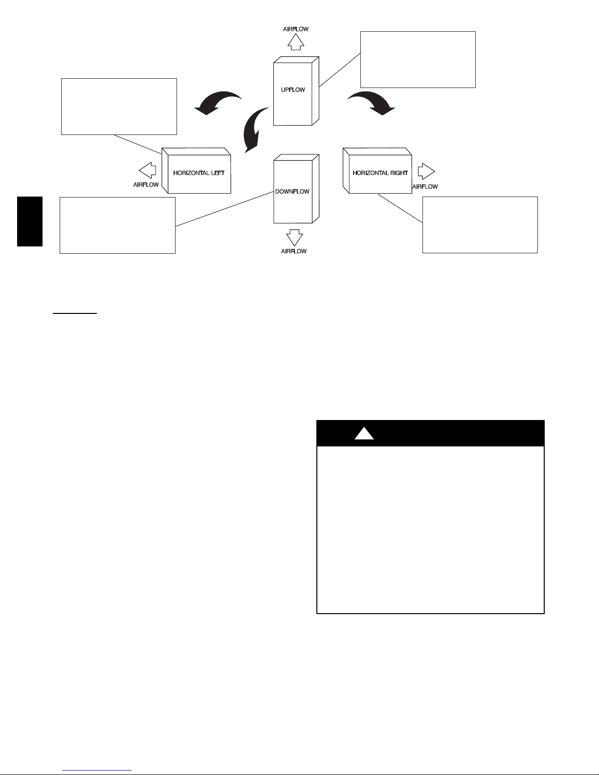
THE BLOWER IS LOCATED
TO THE RIGHT OF THE
BURNER SECTION, AND
AIR CONDITIONED AIR IS
DISCHARGED TO THE LEFT.
THE BLOWER IS
LOCATED BELOW THE
BURNER SECTION, AND
CONDITIONED AIR IS
DISCHARGED UPWARD.
THE BLOWER IS
LOCATED ABOVE THE
BURNER SECTION, AND
312AAV
CONDITIONED AIR IS
DISCHARGED DOWNWARD
LOCATION
GENERAL
This multipoise furnace is shipped in packaged configuration.
Some assembly and modifications are required when used in any
of the four applications shown in Fig. 4.
NOTE: For high--altitude installations, the high--altitude
conversion kit MUST be installed at or above 5500 ft. (1676 M)
above sea level. Obtain high--altitude conversion kit from your
area authorized distributor.
This furnace must:
S be installed so the electrical components are protected from
water.
S not beinstalled directly onany combustible material other than
wood flooring for upflow applications. Downflow installations
require use of a factory--approved floor base or coil assembly
when installed on combustible materials or wood flooring (refer
to SAFETY CONSIDERATIONS).
S be located close to the chimney or vent and attached to an air
distribution system. Refer to Air Ducts section.
S be provided ample space for servicing and cleaning. Always
comply with minimum fire protection clearances shown on the
furnace clearance to combustible construction label.
The following types of furnace installations may require
OUTDOOR AIR for combustion due to chemical exposures:
S Commercial buildings
S Buildings with indoor pools
S Laundry rooms
S Hobby or craft rooms, and
S Chemical storage areas
If air is exposed to the following substances, it should not be used
for combustion air, and outdoor air may be required for
combustion:
S Permanent wave solutions
S Chlorinated waxes and cleaners
S Chlorine based swimming pool chemicals
Fig. 4 -- Multipoise Orientations
S Water softening chemicals
S De--icing salts or chemicals
S Carbon tetrachloride
S Halogen type refrigerants
S Cleaning solvents (such as perchloroethylene)
S Printing inks, paint removers, varnishes, etc.
S Hydrochloric acid
S Cements and glues
S Antistatic fabric softeners for clothes dryers
S Masonry acid washing materials
CARBON MONOXIDE POISONING AND UNIT
DAMAGE HAZARD
Failure to follow this warning could result in personal
injury or death, and furnace damage.
Corrosive or contaminated air may cause failure of parts
containing flue gas, which could leak into the living space.
Air for combustion must not be contaminated by halogen
compounds, which include fluoride, chloride, bromide, and
iodide. These elements can corrode heat exchangers and
shorten furnace life. Air contaminants are found in aerosol
sprays, detergents, bleaches, cleaning solvents, salts, air
fresheners, and other household products. Do not install
furnace in a corrosive or contaminated atmosphere. Make
sure all combustion and circulating air requirements are met,
in addition to all local codes and ordinances.
All fuel--burning equipment must be supplied with air for fuel
combustion. Sufficient air must be provided to avoid negative
pressure in the equipment room or space. A positive seal must be
made between the furnace cabinet and the return--air duct to
prevent pulling air from the burner area and from draft safeguard
opening.
!
WARNING
THE BLOWER IS
LOCATED TO THE LEFT
OF THE BURNER SECTION,
AND CONDITIONED AIR IS
DISCHARGED TO THE RIGHT.
A02097
6
!
WARNING
!
CAUTION
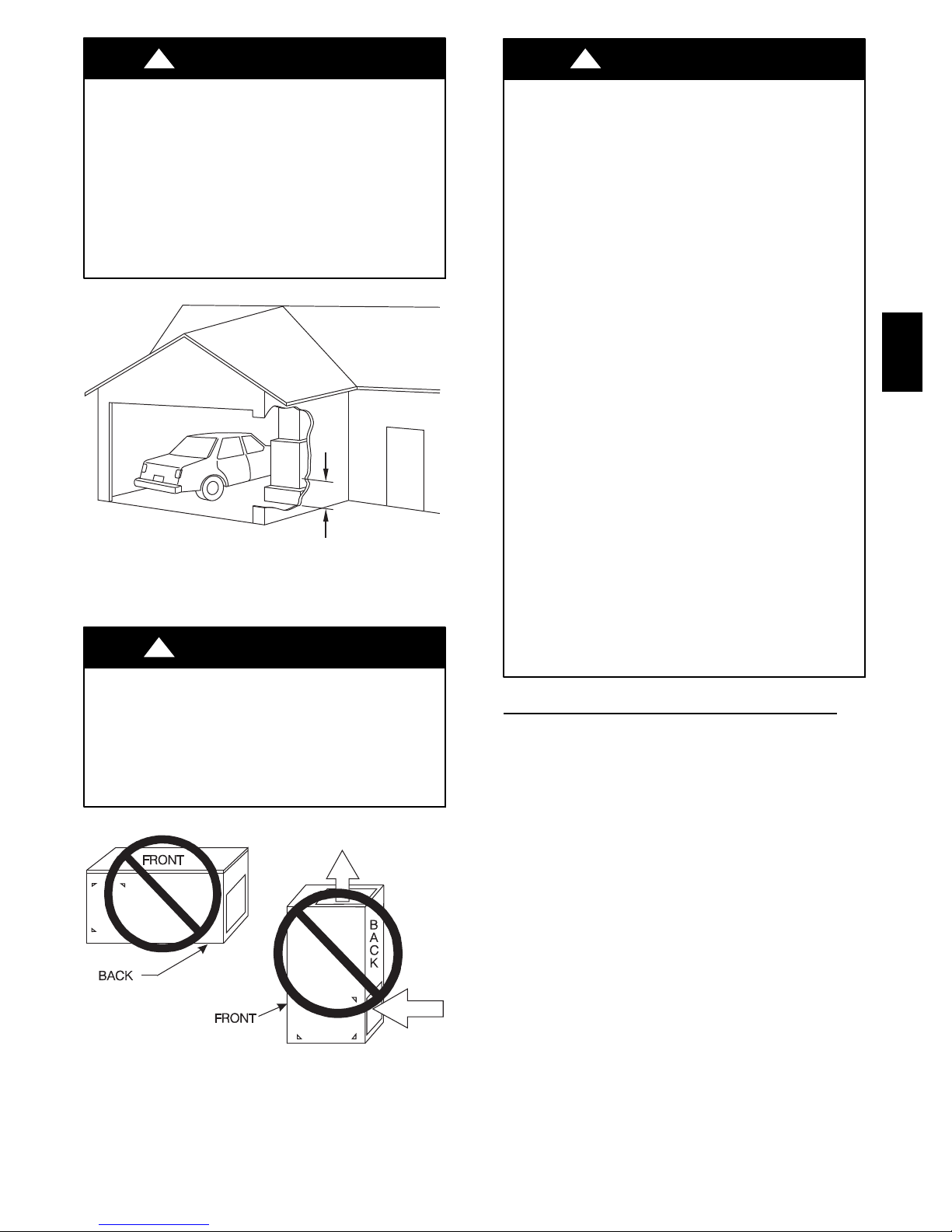
FIRE, INJURY OR DEATH HAZARD
Failure to follow this warning could result in personal
injury, death, and/or property damage.
When the furnace is installed in a residential garage, the
burners and ignition sources must be located at least 18
inches (457 mm) above the floor. The furnace must be
located or protected to avoid damage by vehicles. When the
furnace is installed in a public garage, airplane hangar, or
other building having a hazardous atmosphere, the furnace
must be installed in accordance with the NFGC. (See Fig.
5.)
18-IN. (457.2 mm)
MINIMUM TO BURNERS
A93044
Fig. 5 -- Installation in a Garage
!
WARNING
FIRE HAZARD
Failure to follow this warning could result in personal
injury, death and/or property damage.
Do not install the furnace on its back or hang furnace with
control compartment facing downward. Safety control
operation will be adversely affected. Never connect
return--air ducts to the back of the furnace. (See Fig. 6.)
PROPERTY DAMAGE HAZARD
Improper use or installation of this furnace may cause
premature component failure. This gas furnace may be used
for construction heat provided that:
--The furnace is permanently installed with all electrical
wiring, piping, venting and ducting installed according to
these installation instructions. A return air duct is provided,
sealed to the furnace casing, and terminated outside the
space containing the furnace. This prevents a negative
pressure condition as created by the circulating air blower,
causing a flame roll--out and/or drawing combustion
products into the structure.
--The furnace is controlled by a thermostat. It may not be
”hot wired” to provide heat continuously to the structure
without thermostatic control.
--Clean outside air is provided for combustion. This is to
minimize the corrosive effects of adhesives, sealers and
other construction materials. It also prevents the
entrainment of drywall dust into combustion air, which can
cause fouling and plugging of furnace components.
--The temperature of the return air to the furnace is
maintained between 55_F(13_C) and 80_F(27_C), with
no evening setback or shutdown. The use of the furnace
while the structure is under construction is deemed to be
intermittent operation per our installation instructions.
--The air temperature rise is within the rated rise range on
the furnace rating plate, and the gas input rate has been set
to the nameplate value.
--The filters used to clean the circulating air during the
construction process must be either changed or thoroughly
cleaned prior to occupancy.
--The furnace, ductwork and filters are cleaned as necessary
to remove drywall dust and construction debris from all
HVAC system components after construction is completed.
--Verify proper furnace operating conditions including
ignition, gas input rate, air temperature rise, and venting
according to these installation instructions.
LOCATION RELATIVE TO COOLING EQUIPMENT
The cooling coil must be installed parallel with, or on the
downstream side of the unit to avoid condensation in the heat
exchangers. When installed parallel with the furnace, dampers or
other flow control must prevent chilled air from entering the
furnace. If the dampers are manually operated, they must be
equipped with means to prevent operation of either unit unless
the damper is in the full--heat or full--cool position.
312AAV
Fig. 6 -- Prohibit Installation on Back
AIR FOR COMBUSTION AND
VENTILATION
Provisions for adequate combustion, ventilation, and dilution air
must be provided in accordance with:
U.S. installations: Section 9.3 of the NFPA 54 /A ANSI
Z223.1--2009, Air for Combustion and Ventilation, and
applicable provisions of the local building codes.
A02054
7
!
CAUTION
FURNACE CORROSION HAZARD
Failure to follow this caution may result in furnace damage.
Air for combustion must not be contaminated by halogen
compounds, which include fluoride, chloride, bromide, and
iodide. These elements can corrode heat exchangers and
shorten furnace life. Air contaminants are found in aerosol
sprays, detergents, bleaches, cleaning solvents, salts, air
fresheners, and other household products.
!
WARNING
CARBON MONOXIDE POISONING HAZARD
Failure to follow this warning could result in personal
injury or death.
The operation of exhaust fans, kitchen ventilation fans,
312AAV
clothes dryers, attic exhaust fans or fireplaces could create a
NEGATIVE PRESSURE CONDITION at the furnace.
Make--up air MUST be provided for the ventilation devices,
in addition to that required by the furnace. Refer to Carbon
Monoxide Poisoning Hazard warning in venting section of
these instructions to determine if an adequate amount of
make--up air is available.
The requirements for combustion and ventilation air depend upon
whether or not the furnace is located in a space having a volume
of at least 50 cubic feet per 1,000 Btuh input rating for all gas
appliances installed in the space.
S Spaces having less than 50 cubic feet per 1,000 Btuh require the
Outdoor Combustion Air Method.
S Spaces having at least 50 cubic feet per 1,000 Btuh may use the
Indoor Combustion Air, Standard orKnown Air Infiltration
Method.
Outdoor Combustion Air
Method
1. Provide the space with sufficient air for proper combustion, ventilation, and dilution of flue gases using permanent horizontal or vertical duct(s) or opening(s) directly
communicating with the outdoors or spaces that freely
communicate with the outdoors.
2. Fig. 7 illustrates how to provide TWO OUTDOOR
OPENINGS, one inlet and one outlet combustion and
ventilation air opening, to the outdoors.
e. One opening MUST commence within 12 in. (300 mm)
of the ceiling and the second opening MUST commence
within 12 in. (300 mm) of the floor.
f. Size openings and ducts per Fig. 7 and Table 2.
2
g. TWOHORIZONTALDUCTS require1 --in
per 2,000 Btuh (1,100 mm
2
/kW) of combined input for
of freearea
all gas appliances in the space per Fig.7 and Table 2.
h. TWO OPENINGS OR VERTICAL DUCTS require 1
2
of free area per 4,000Btuh (550mm2/kW) for com-
-- i n
bined input of all gas appliances in the space per Fig. 7
and Table 2.
3. ONE OUTDOOR OPENING requires:
a. One square inch of free area per 3,000 Btuh (734
2
/kW)for combined input of all gas appliancesin the
mm
space per Table 2 and
b. Not less than the sum of the areas of all vent connectors
in the space.
Table 2 – Minimum Free Area Required for Each Combustion Air opening of Duct to Outdoors
FURNACE
INPUT
(BTUH)
44,000 22 (14194) 6 (152) 14.7 (9484) 5 (127) 11 (7096) 4 (102)
66,000 33 (21290) 7 (178) 22 (14193) 6 (152) 16.5 (10645) 5 (127)
88,000 44 (28387) 8 (203) 29.3 (18903) 7 (178) 22 (14193) 6 (152)
110,000 55 (35484) 9 (229) 36.7 (23677) 7 (178) 27.5 (17742) 6 (152)
132,000 66 (42580) 10 (254) 44 (28387) 8 (203) 33 (21290) 7 (178)
154,000 77 (49677) 10 (254) 51.3 (33096) 9 (229) 38.5 (24839) 8 (203)
TWO HORIZONTAL DUC TS SINGLE DUCT OR OPENING TWO OPENINGS OR VERTICAL DUCTS
(1 SQ. IN./2,000 BTUH) (1,100 SQ. MM/KW) (1 SQ. IN./3,000 BTUH) (734 SQ. MM/KW) (1 SQ. IN./4,000 BTUH) (550 SQ. MM/KW)
Free Area of Opening
and Duct
Sq. In. (Sq. mm)
Round Duct
Dia.
In. (mm)
Free Area of Opening
and Duct
Sq. In. (Sq. mm)
Round Duct
Dia.
In. (mm)
Free Area of Opening
and Duct
Sq. In. (Sq. mm)
Round Duct
Dia.
In. (mm)
EXAMPLES: Determining Free Area
FURNACE WATER HEATER TOTAL INPUT
110,000 + 30,000 = (140,000 divided by 4,000) = 35.0 Sq. In. for each two Vertical Ducts or Openings
66,000 + 40,000 = (106,000 divided by 3,000) = 35.3 Sq. In. for a Single Duct or Opening
88,000
+ 30,000 = (118,000 divided by 2,000) = 59.0 Sq. In. for each of two Horizontal Ducts
8
1 SQ IN.
E
12 ″ MAX
(305mm)
1 SQ IN.
PER 4000
BTUH*
PER 4000
BTUH*
F
1 SQ IN .
BTUH*
1 SQ IN .
BTUH*
G
12 ″
MAX
PER
4000
OUTDOORS
PER
4000
12 ″
MAX
DUCTS
TO
O UTDOORS
(305mm)
12 ″ MAX
1 SQ IN.
PER 2000
BTUH*
DUCT S
TO
OUTDOORS
1 SQ IN.
PER 2000
BTUH*
(305mm)
12 ″ MAX
CIRCULA TING AIR DUCT S
*Minimum dimensions of 3 ---in. (76 mm).
Note: Use any of the following combinations of openings:
A&BC&DD&EF&G
B
AIR DUCTS
C IRCULA TING
A
OF COMB USTION AIR
CLEARANCE IN FRONT
D
VENT
THR OUGH
R OOF
(76mm)
AT LEAST 3 IN .
OPENINGS SHALL BE
C
DUCT
TO
OUTDOORS
Fig. 7 -- Air for Combustion, Ventilation, and Dilution for
Outdoors
(305mm)
(305mm)
A03174
CIRCULATING AIR
DUCTS
INTERIOR
HEATED
SPACE
CIRCULATING AIR DUCTS
* Minimum opening size is 100 sq in. (64516 sq. mm) with minimum
dimensions of 3 in. (76 mm)
†Minimumof3in.(76mm)whentype-B1ventisused.
VENT THROUGH ROOF
12" MAX
1 SQ IN.
PER 1000
BTUH* IN DOOR
OR WALL
UNCONFINED
SPACE
(152mm)
6" MIN
(FRONT)
1 SQ IN.
PER 1000
BTUH* IN DOOR
OPENINGS SHALL BE AT LEAST 3 IN.
OR WALL
CLEARANCE IN FRONT OF COMBUSTION AIR
12" MA X
(305mm)
Ü
(305mm)
A03175
Fig. 8 -- Air for Combustion, Ventilation, and Dilution from
Indoors
312AAV
The opening shall commence within 12 in. (300 mm) of the
ceiling. Appliances in the space shall have clearances of at least 1
in. (25 mm) from the sides and back and 6 in. (150 mm) from the
front. The opening shall directly communicate with the outdoors
or shall communicate through a vertical or horizontal duct to the
outdoors or spaces (crawl or attic) that freely communicate with
the outdoors.
Indoor Combustion Air
Known--Air--Infiltration Rate
E NFPA & AGA Standard and
Methods
Indoor air is permitted for combustion, ventilation, and dilution,
if the Standard or Known--Air--Infiltration Method is used.
!
WARNING
CARBON MONOXIDE POISONING HAZARD
Failure to follow this warning could result in death and/or
personal injury.
Many homes require air to be supplied from outdoors for
furnace combustion, ventilation, and dilution of flue gases.
The furnace combustion air supply must be provided in
accordance with this instruction manual.
The Standard Method:
1. The space has no less volume than 50 cubic feet per 1,000
Btuh of the maximum input ratings for all gas appliances
installed in the space and
2. The air infiltration rate is not known to be less than 0.40
air changes per hour (ACH).
The Known Air Infiltration Rate Method shall be used, if the
infiltration rate is known to be:
1. Less than 0.40 ACH and
2. Equal to or greater than 0.10 ACH
Infiltration rates greater than 0.60 ACH shall not be used. The
minimum required volume ofthe space varies with the number of
ACH and shall be determined per Table 3 or Equations 1 and 2.
Determine the minimum required volume for each appliance in
the space and add the volumes together to get the total minimum
required volume for the space.
9
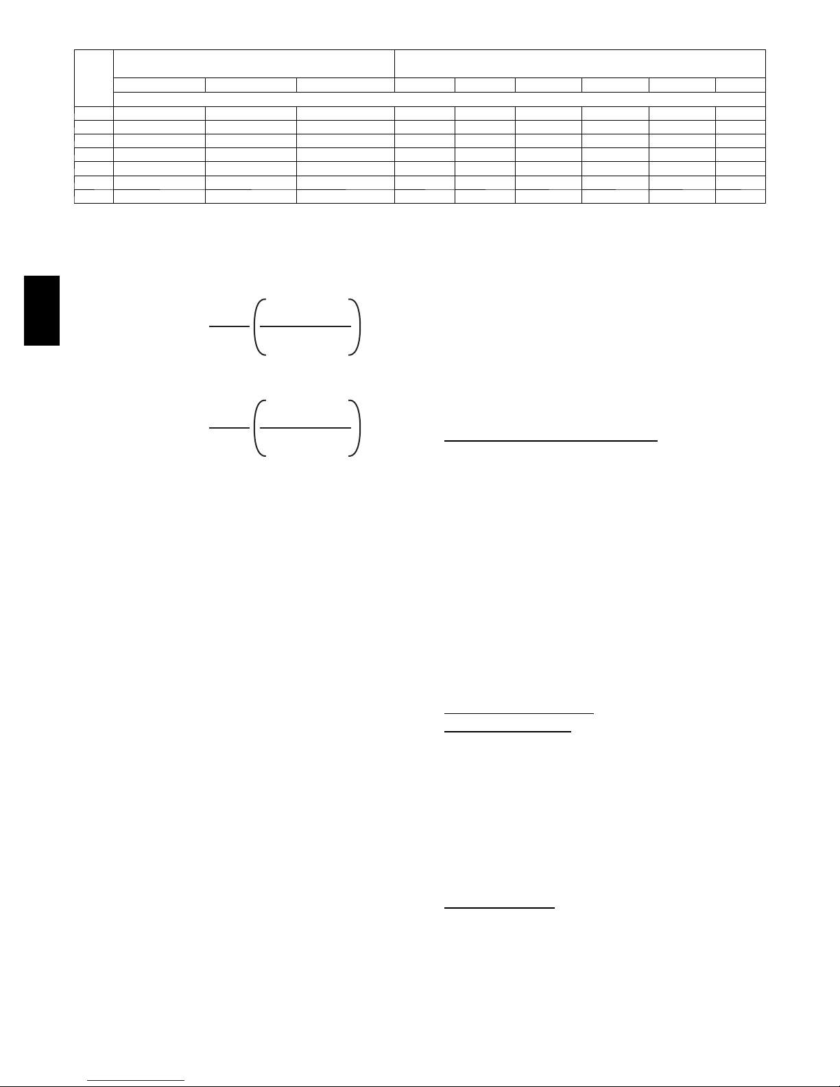
Table 3 – Minimum Space Volumes for 100% Combustion, Ventilation, and Dilution from Indoors
OTHER THAN FAN---ASSISTED TOTAL
ACH
0.60 1,050 1,400 1,750 1,100 1,650 2,200 2,750 3,300 3,850
0.50 1,260 1,680 2,100 1,320 1,980 2,640 3,300 3,960 4,620
0.40 1,575 2,100 2,625 1,650 2,475 3,300 4,125 4,950 5,775
0.30 2,100 2,800 3,500 2,200 3,300 4,400 5,500 6,600 7,700
0.20 3,150 4,200 5,250 3,300 4,950 6,600 8,250 9,900 11,550
0.10 6,300 8,400 10,500 6,600 9,900 13,200 16,500 19,800 23,100
0.00 NP NP NP NP NP NP NP NP NP
NP = Not Permitted
Table 3--Minimum Space Volumes were determined by using
the following equations from the National Fuel Gas Code ANSI
Z223.1--2009/NFPA 54--2009, 9.3.2.2:
1. For other than fan--assisted appliances, such as a draft
hood--equipped water heater:
312AAV
Volume
2. For fan--assisted appliances such as this furnace:
Volume
If:
= combined input of all other than fan--assisted
I
other
= combined input of all fan--assisted appliances in
I
fan
ACH = air changes per hour (ACH shall not exceed 0.60.)
The following requirements apply to the Standard Method and
to the Known Air Infiltration Rate Method.
1. Adjoining rooms can be considered part of a space if:
a. There are no closeable doors between rooms.
b. Combining spaces on same floor level. Each opening
shall have free area of at least 1 in.
mm
in the space, but not less than 100 in.
opening shall commence within 12 in. (300 mm) of the
ceiling and the second opening shall commence within
12 in. (300 mm) of the floor. The minimum dimension
of air openings shall be at least 3 in. (80 mm). (See Fig.
8.)
c. Combining space on different floor levels. The volumes
of spaces on different floor levels shall be considered as
communicating spaces if connected by oneor morepermanent openings in doors or floors having free area of
at least 2 in.
rating of all gas appliances.
2. An attic or crawlspace may be considered a space that
freely communicates with the outdoors provided there are
adequate permanent ventilation openings directly to outdoors having free area of at least 1--in.2/4,000 Btuh of
total input rating for all gas appliances in the space.
3. In spaces that use the Indoor Combustion Air Method, in-
filtration should be adequate to provide air for combustion, permanent ventilation and dilution of flue gases.
(1,000s BTUH GAS INPUT RATE)
30 40 50 44 66 88 110 132 154
SpaceVolume(ft.3)
3
21ft
=
Other
Fan
appliances in Btuh/hr
Btuh/hr
2
/kW) of the total input rating of all gas appliances
ACH
3
15ft
=
ACH
2
/1,000 Btuh (4,400 mm2/kW) of totalinput
I
other
1000 Btu/hr
I
fan
1000 Btu/hr
2
/1,000 Btuh (2,000
2
(0.06 m2). One
A04002
Combination of Indoor and Outdoor
1. Indoor openings shall comply with the Indoor Combus-
A04003
2. Outdoor openings shall be located as required in the Out-
3. Outdoor openings shall be sized as follows:
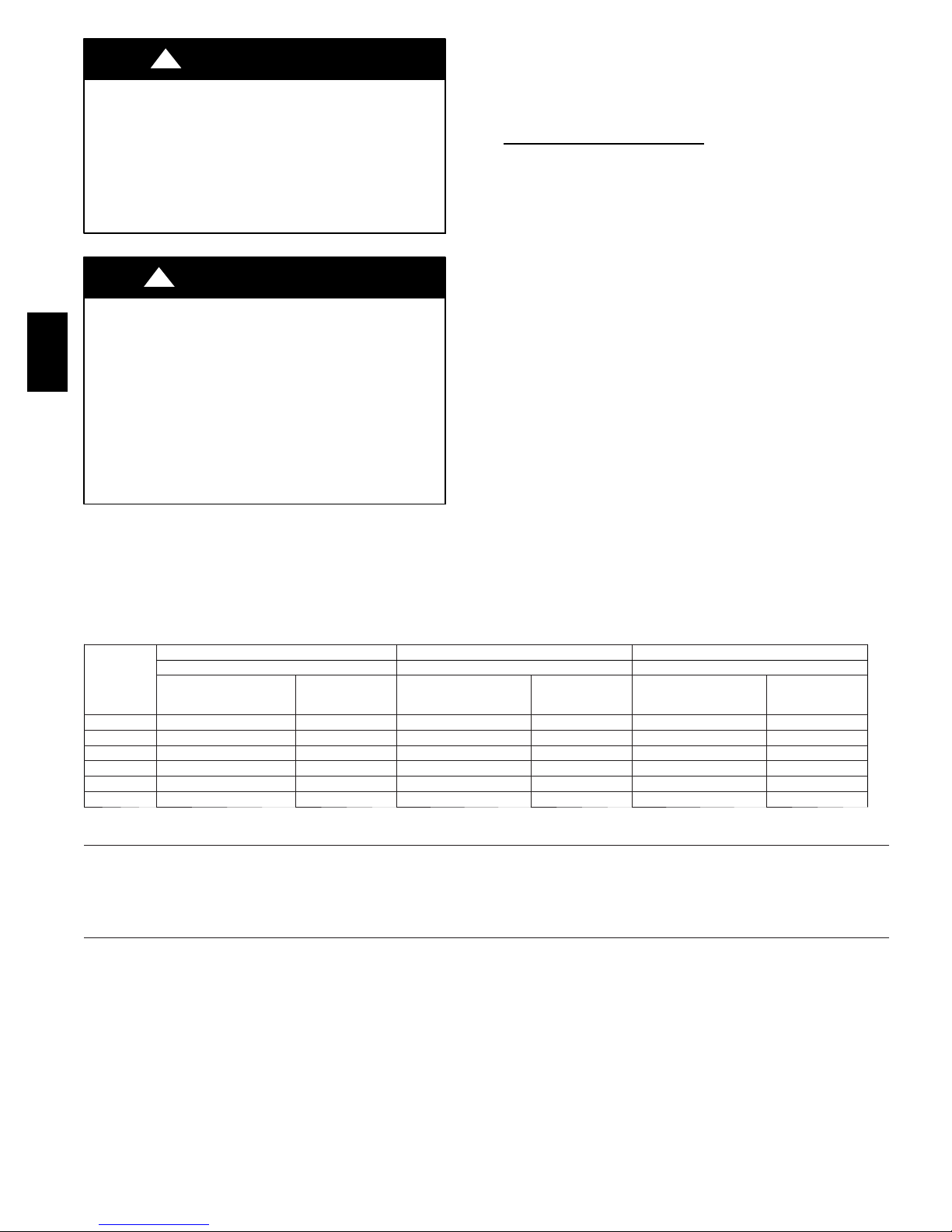
UPFLOW INSTALLATION
Bottom Return Air
These furnaces are shipped with bottom closure panel installed in
bottom return--air opening. Remove and discard this panel when
bottom return air is used. To remove bottom closure panel,
perform the following:
1. Tilt or raise furnace and remove 2 screws holding bottom
2. Rotate bottom filler panel downward to release holding
3. Remove bottom closure panel.
4. Reinstall bottom filler panel and screws.
Side Return Air
These furnaces are shipped with bottom closure panel installed in
bottom return--air opening. This panel MUST be in place when
only side return air is used.
FAN---ASSISTED TOTAL
(1,000s BTUH GAS INPUT RATE)
However, in buildings with unusually tight construction,
additional air MUST be provided using the methods described in the Outdoor Combustion Air Method section.
Unusually tight construction is defined as Construction
with:
a. Walls and ceilings exposed to the outdoors have a con-
tinuous, sealed vapor barrier. Openings are gasketed or
sealed and
b. Doors and openable windows are weatherstripped and
c. Other openings are caulked or sealed. These include
joints around window and door frames, between sole
plates and floors, between wall--ceiling joints, between
wall panels, at penetrations for plumbing, electrical and
gas lines, etc.
Air
tion Air Method below and,
door Combustion Air Method mentioned previously and,
a. Calculate the Ratio of all Indoor Space volume divided
by required volume for IndoorCombustion Air Meth-
od below.
b. Outdoor opening size reduction Factor is 1 minus the
Ratio in a. above.
c. Minimum size of Outdoor openings shall be the size re-
quiredinOutdoorCombustionAirMethodabovemul-
tiplied by reduction Factor in b. above. The minimum
dimension ofair openings shall be not lessthan 3 in. (80
mm).
INSTALLATION
Inlet
filler panel. (See Fig. 9.)
tabs.
Inlet
10
NOTE: Side return--air openings can be used in UPFLOW and
most HORIZONTAL configurations. Do not use side return--air
openings in DOWNFLOW configuration.
Bottom
Closure Panel
Bottom Filler Panel
A10273
Fig. 9 -- Removing Bottom Closure Panel
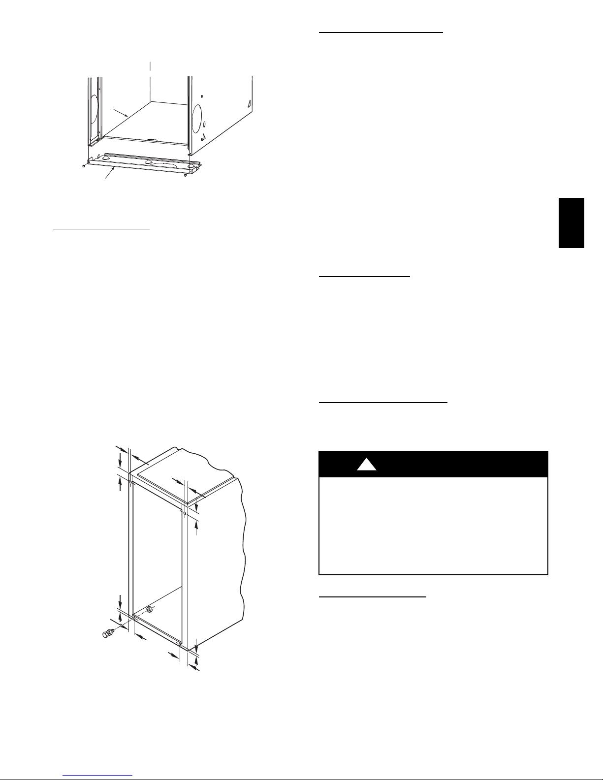
Leveling Legs (If Desir
ed)
In upflow position with side return inlet(s), leveling legs may be
used. (See Fig. 10.) Install field--supplied, 5/16 x 1--1/2 in. (8 x
38 mm) (max) corrosion--resistant machine bolts, washers and
nuts.
NOTE: Bottom closure must be used when leveling legs are
used. It may be necessary to remove and reinstall bottom closure
panel to install leveling legs. To remove bottom closure panel, see
item 1 in Bottom Return Air Inlet section in Step 1 above.
To install leveling legs:
1. Position furnace on its back. Locate and drill a hole in
each bottom corner of furnace. (See Fig. 10.)
2. For each leg, install nut on bolt and then install bolt and
nut in hole. (Install flat washer if desired.)
3. Install another nut on other side of furnace base. (Install
flat washer if desired.)
4. Adjust outside nut to provide desired height, and tighten
inside nut to secure arrangement.
5. Reinstall bottom closure panel if removed.
5/
16 ″
(8mm)
(8mm)
5/
16 ″
1 3 / 4 ″
(44mm)
3
1
/ 4 ″
(44mm)
(8mm)
5
/ 16 ″
(8mm)
5/
16 ″
1
(44mm)
3/
4 ″
3/
1
4 ″
A89014
(44mm)
Fig. 10 -- Leveling Legs
DOWNFLOW INSTALLA
TION
NOTE: For downflow applications, this furnace is approved for
use on combustible flooring when any one of the following 3
accessories are used:
S Special Base, KGASB
S Cased Coil Assembly Part No. CNPV, CNRV, CAP, and CAR
S Coil Box Part No. KCAKC
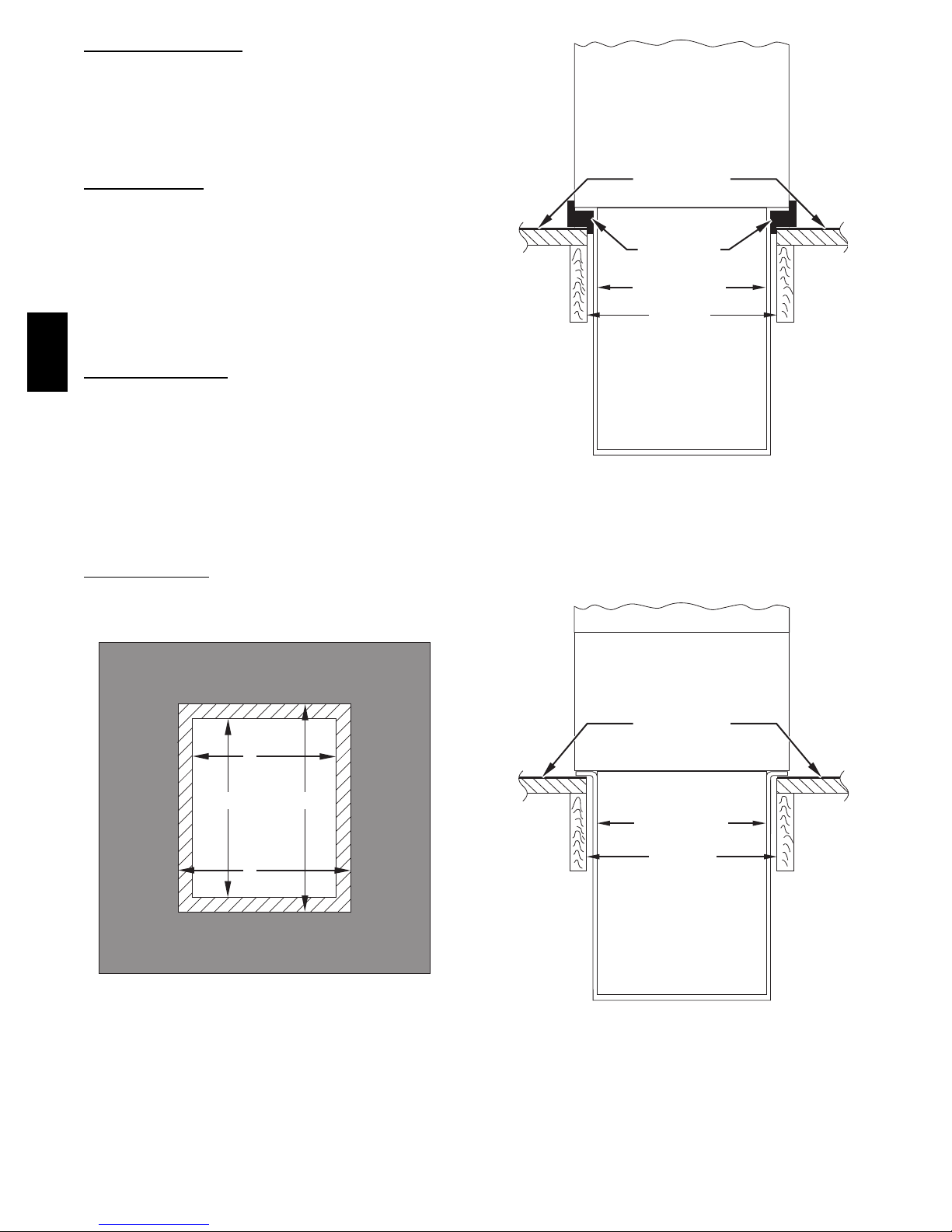
1. Determine application being installed from Table 4.
2. Construct hole in floor per Table 4 and Fig. 11.
3. Construct plenum to dimensions specified in Table 4 and
Fig. 11.
4. If downflow subbase, KGASB is used, install as shown in
Fig. 12. If Coil Assembly Part No. CNPV, CNRV, CAP,
CAR or Coil Box Part No. KCAKC is used, install as
shown in Fig. 13.
NOTE: It is recommended that the perforated supply--air duct
flanges be completely folded over or removed from furnace when
installing the furnace on a factory--supplied cased coil or coil box.
To remove the supply--air duct flange, use wide duct pliers or
hand seamers to bend flange back and forth until it breaks off. Be
careful of sharp edges. (See Fig. 14.)
Bottom Return Air
Inlet
These furnaces are shipped with bottom closure panel installed in
bottom return--air opening. Remove and discard this panel when
bottom return air is used. To remove bottom closure panel,
perform the following:
1. Tilt or raise furnace and remove 2 screws holding bottom
filler panel. (See Fig. 9.)
2. Rotate bottom filler panel downward to release holding
tabs.
3. Remove bottom closure panel.
4. Reinstall bottom filler panel and screws.
HORIZONTAL INSTALLA
TION
The furnace can be installed horizontally in an attic or crawl space
on either the left--hand (LH) or right--hand (RH) side. The furnace
can be hung from floor joists, rafters or trusses or installed on a
non--combustible platform, blocks, bricks or pad.
!
WARNING
FIRE, EXPLOSION, AND CARBON MONOXIDE
POISONING HAZARD
Failure to follow this warning could result in personal
injury, death, or property damage.
Do not install the furnace on its back or hang furnace with
control compartment facing downward. Safety control
operation will be adversely affected. Never connect
return--air ducts to the back of the furnace.
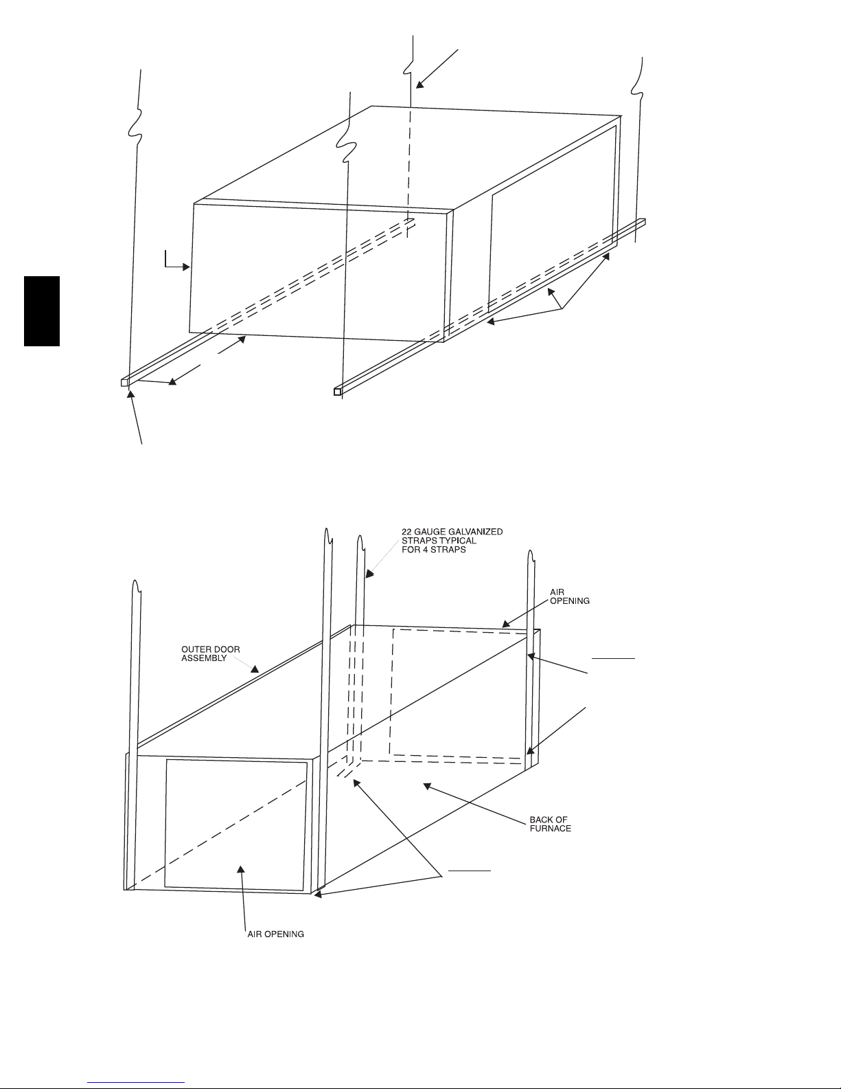
Suspended Furnace Support
The furnace may be supported under each end with threaded rod,
angle iron or metal plumber’s strap as shown. (See Fig. 15 and
16.) Secure angle iron to bottom of furnace as shown.
Heavy--gauge sheet metal straps (plumber’s straps) may be used
to suspend the furnace from each bottom corner. To prevent
screws from pulling out, use 2 #8 x 3/4--in. (19 mm) screw into
the side and 2 #8 x 3/4--in. (19 mm) screw in the bottom of the
furnace casing for each strap. (See Fig. 15 and 16.)
If the screws are attached to ONLY the furnace sides and not the
bottom, the straps must be vertical against the furnace sides and
not pull away from the furnace sides, so that the strap attachment
screws are not in tension (are loaded in shear) for reliable support.
312AAV
11
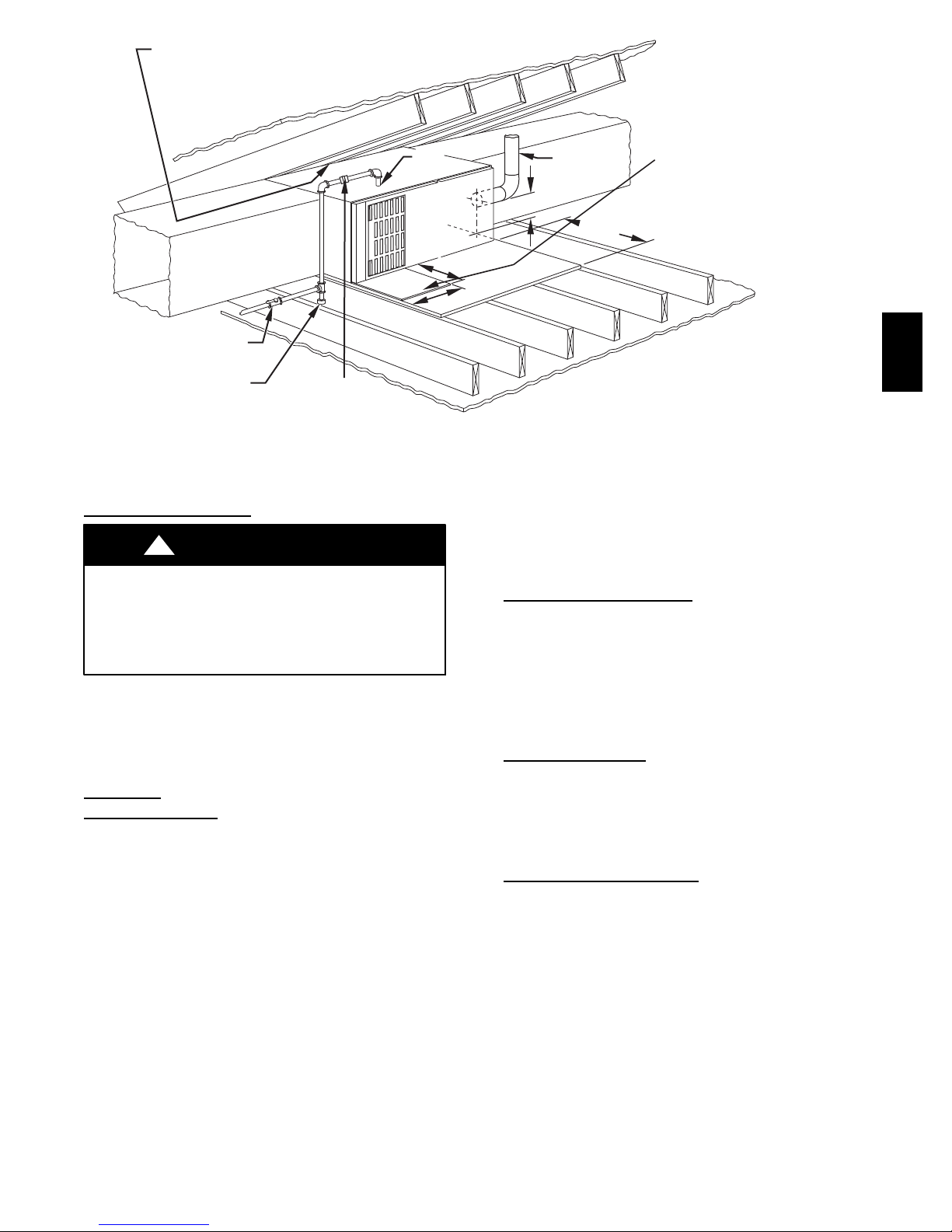
Platform Furnace
Support
Construct working platform at location where all required furnace
clearances are met. (See Fig. 2 and 17.) For furnaces with 1--in.
(25 mm) clearance requirement on side, set furnace on
non--combustible blocks, bricks or angle iron. For crawlspace
installations, if the furnace is not suspended from the floor joists,
the ground underneath furnace must be level and the furnace set
on blocks or bricks.
Roll--Out Pr
otection
Provide a minimum 17--3/4--in. x 22--in. (451 x 559 mm) piece of
sheet metal for flame roll--out protection in front of burner area
for furnaces closer than 12 inches (305 mm) above the
combustible deck or suspended furnaces closer than 12 inches
(305 mm) to joists. The sheet metal MUST extend underneath the
furnace casing by 1 in. (25 mm) with the door removed.
The bottom closure panel on furnaces of widths 17--1/2 in. (445
mm) and larger may be used for flame roll--out protection when
bottom of furnace is used for return air connection. See Fig. 17.
for proper orientation of roll--out shield.
Bottom Return Air
312AAV
Inlet
These furnaces are shipped with bottom closure panel installed in
bottom return--air opening. Remove and discard this panel when
bottom return air is used. To remove bottom closure panel,
perform the following:
1. Tilt or raise furnace and remove 2 screws holding bottom
filler panel. (See Fig. 9.)
2. Rotate bottom filler panel downward to release holding
tabs.
3. Remove bottom closure panel.
4. Reinstall bottom filler panel and screws.
Side Return Air
Inlet
These furnaces are shipped with bottom closure panel installed in
bottom return--air opening. This panel MUST be in place when
side return air inlet(s) are used without a bottom return air inlet.
FURNACE
(OR COIL CASING
WHEN USED)
COMBUSTIBLE
FLOORING
DOWNFLOW
SUBBASE
SHEET METAL
PLENUM
FLOOR
OPENING
Fig. 12 -- Furnace, Plenum, and Subbase installed on a
Combustible Floor
FURNACE
APPROVED
COIL ASSEMBLY
OR
COIL BOX
A96285
A
PLENUM
OPENING
B
OPENING
D
FLOOR
C
Fig. 11 -- Floor and Plenum Opening Dimensions
A96283
COMBUSTIBLE
FLOORING
SHEET METAL
PLENUM
FLOOR
OPENING
A08556
Fig. 13 -- Furnace, Plenum, and Coil Assembly or Coil Box
Installed on a Combustible Floor
12
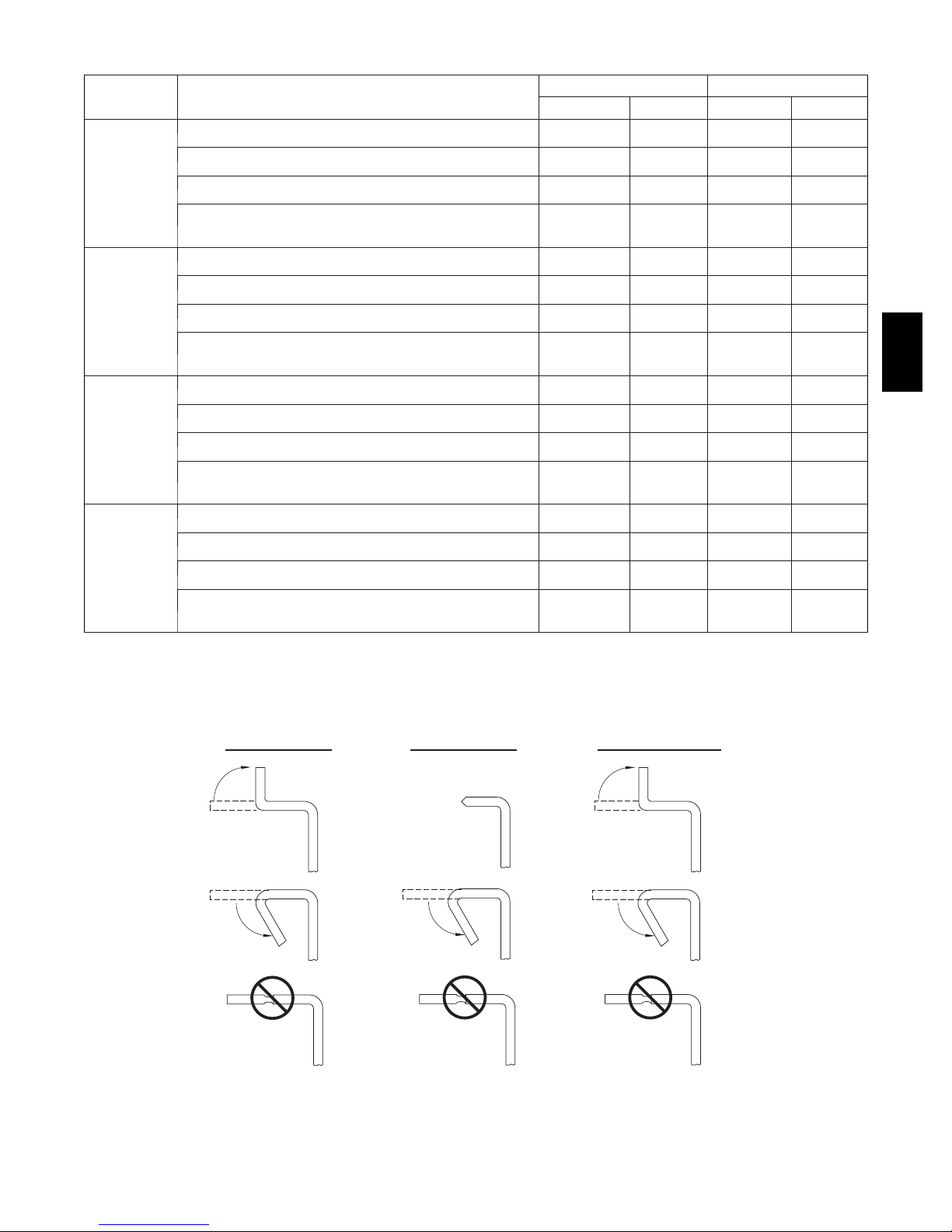
Table 4 – Opening dimensions -- In. (mm)
FURNACE
CASING
WIDTH
14–3/16
(376)
17–1/2
(445)
21
(533)
24--- 1/2
(622)
APPLICATION
Upflow Applications on Combustible or Noncombustible Floor-
ing (KGASB subbase not required)
Downflow Applications on Noncombustible Flooring (KGASB
subbase not required)
Downflow applications on combustible flooring (KGASB sub-
base required)
Downflow Applications on Combustible Flooring with CNPV,
CNRV, CAR, or CAP Coil Assembly or KCAKC coil box
(KGASB subbase not required)
Upflow Applications on Combustible or Noncombustible Floor-
ing (KGASB subbase not required)
Downflow Applications on Noncombustible Flooring (KGASB
subbase not required)
Downflow applications on Combustible flooring (KGASB sub-
base required)
Downflow Applications on Combustible Flooring with CNPV,
CNRV, CAR, or CAP Coil Assembly or KCAKC coil box
(KGASB subbase not required)
PLENUM OPENING FLOOR OPENING
A B C D
12--- 11/16
(322)
12--- 9/16
(319)
11--- 13/16
(284)
12--- 5/16
(319)
16
(406)
15--- 7/8
(403)
15--- 1/8
(384)
15--- 1/2
(394)
19--- 1/2
(495)
19--- 3/8
(492)
18--- 5/8
(473)
19
(483)
23
(584)
22--- 7/8
(581)
22--- 1/8
(562)
22--- 1/2
(572)
21--- 5/8
(549)
19
(483)
19
(483)
19
(483)
21--- 5/8
(549)
19
(483)
19
(483)
19
(483)
21--- 5/8
(549)
19
(483)
19
(483)
19
(483)
21--- 1/8
(537)
19
(483)
19
(483)
19
(483)
13--- 5/16
(338)
13--- 3/16
(335)
13--- 7/16
(341)
13--- 5/16
(338)
16--- 5/8
(422)
16--- 1/2
(419)
16--- 3/4
(425)
16--- 1/2
(419)
20--- 1/8
(511)
20
(508)
20--- 1/4
(514)
20
(508)
23--- 5/8
(600)
23--- 1/2
(597)
23--- 3/4
(603)
23--- 1/2
(597)
22--- 1/4
(565)
19--- 5/8
(498)
20--- 5/8
(600)
20
(508)
22--- 1/4
(565)
19--- 5/8
(498)
20--- 5/8
(600)
20
(508)
22--- 1/4
(565)
19--- 5/8
(498)
20--- 5/8
(600)
20
(508)
22--- 1/4
(565)
19--- 5/8
(498)
20--- 5/8
(600)
20
(508)
312AAV
UPFLOW DOWNFLOW HORIZONTAL
120°
MIN
90°
YES
YES
NO
YES
120°
MIN
YES
Fig. 14 -- Duct Flanges
13
NO
120°
MIN
90°
YES
YES
NO
A02020
1
/
4 " (6mm) THREADED ROD
4 REQ.
OUTER DOOR
A S SEMBLY
SECURE ANGLE
312AAV
8" (203mm)
FOR DOOR REMOVAL
MIN
1” (25mm) SQUARE, 1-1/4”x1-1/4”x1/8” (32x32x3mm)
ANGLE IRON OR UNI-STRUT MAY BE USED
IRON TO BOTTOM
OF FURNACE WITH
3
/4" (19mm) SCREWS
3 #8 x
TYPICAL FOR 2 SUPPORTS
(2) HEX NUTS, (2) WASHERS & (2) LOCK WASHERS
REQ. PER ROD
Fig. 15 -- Horizontal Unit Suspension
METHOD 2
USE (4) #8 x 3/4 (19 mm) SHEET
METAL SCREWS FOR EACH
STRAP. THE STRAPS
SHOULD BE VERTICAL
AGAINST THE FURNACE
SIDES AND NOT PULL AWAY
FROM THE FURNACE
SIDES.
A10130
METHOD 1
FOLD ALL STRAPS UNDER
FURNACE AND SECURE WTH
(4) #8 x 3/4 (19 mm) SHEET METAL SCREWS
(2 SCREWS IN SIDE AND 2 SCREWS
IN BOTTOM).
Fig. 16 -- Horizontal Suspension with Straps
14
A10131
LINE CONT A CT ONL Y PERMISSIBLE BETWEEN
LINES FORMED BY INTERSECTIONS OF
THE T OP AND TW O SIDES OF THE FURNA CE
JA CKET AND BUILDING JOISTS ,
STUDS , OR FRAMING.
EQUIPMENT MANU AL
SHUT -OFF GAS VA LV E
SEDIMENT
TRAP
UNION
SHEET
MET AL
GAS
ENTR Y
17 3 / 4 ″
22
(559mm)
″
(451mm)
6 ″
M IN
TYPE-B
VENT
(152mm)
*
Fig. 17 -- Typical Attic Installation
17 3 / 4 ″
4 3 / 4 ″
1 ″
(25mm)
EXTEND OUT 12 ″
FR OM FA CE OF DOOR
30-IN . (762mm)
MIN WORK AREA
(451mm)
(121mm)
* WHEN USED W ITH
SINGLE W ALL VEN T
CONNECTIONS
OVERALL
UNDER DOOR
UNDER FURNACE
(305mm)
312AAV
A10164
Not all horizontal furnaces are approved for side return air
connections. (See Fig. 20.)
FILTER
ARRANGEMENT
!
WARNING
CARBON MONOXIDE POISONING HAZARD
Failure to follow this warning could result in personal
injury, or death.
Never operate a furnace without a filter or with filter access
door removed.
There are no provisions for an internal filter rack in these
furnaces. A field--supplied, accessory external filter rack is
required.
Refer to the instructions supplied with the external filter rack for
assembly and installation options.
DUCTS
AIR
General Requir
ements
The duct system should be designed and sized according to
accepted national standards such as those published by: Air
Conditioning Contractors Association (ACCA), Sheet Metal and
Air Conditioning Contractors National Association (SMACNA)
or American Society of Heating, Refrigerating and Air
Conditioning Engineers (ASHRAE) or consult The Air Systems
Design Guidelines reference tables available from your local
distributor. The duct system should be sized to handle the
required system design CFM at the design external static pressure.
The furnace airflow rates are provided in Table 5--Air Delivery
CFM (With Filter).
When a furnace is installed so that the supply ducts carry air
circulated by the furnace to areas outside the space containing the
furnace, the return air shall also be handled by duct(s) sealed to
the furnace casing and terminating outside the space containing
the furnace.
Secure ductwork with proper fasteners for type of ductwork used.
Seal supply-- and return--duct connections to furnace with code
approved tape or duct sealer.
NOTE: Flexible connections should be used between ductwork
and furnace to prevent transmission of vibration.
Ductwork passing through unconditioned space should be
insulated to enhance system performance. When air conditioning
is used, a vapor barrier is recommended.
Maintain a 1--in. (25 mm) clearance from combustible materials
to supply air ductwork for a distance of 36 in. (914 mm)
horizontally from the furnace. See NFPA 90B or local code for
further requirements.
Ductwork Acoustical Tr
eatment
NOTE: Metal duct systems that do not have a 90_ elbow and 10
ft. (3 M) of main duct to the first branch take--off may require
internal acoustical lining. As an alternative, fibrous ductwork may
be used if constructed and installed in accordance with the latest
edition of SMACNA construction standard on fibrous glass
ducts. Both acoustical lining and fibrous ductwork shall comply
with NFPA 90B as tested by UL Standard 181 for Class 1 Rigid
air ducts.
Supply Air
Connections
For a furnace not equipped with a cooling coil, the outlet duct
shall be provided with a removable access panel. This opening
shall be accessible when the furnace is installed and shall be of
such a size that the heat exchanger can be viewed for possible
openings using light assistance or a probe can be inserted for
sampling the air stream. The cover attachment shall prevent leaks.
Upflow and Horizontal
Furnaces
Connect supply--air duct to flanges on furnace supply--air outlet.
Bend flange upward to 90_ with wide duct pliers. (See Fig. 14.)
The supply--air duct must be connected to ONLY the furnace
supply--outlet--air duct flanges or air conditioning coil casing
(when used). DO NOT cut main furnace casing side to attach
supply air duct, humidifier, or other accessories. All accessories
MUST be connected to duct external to furnace main casing.
NOTE: For horizontal applications, the top--most flange may be
bent past 90_ to allow the evaporator coil to hang on the flange
temporarily while the remaining attachment and sealing of the
coil are performed.
15

Table 5 – Air Delivery -- CFM (With Filter)*
FURNACE
SIZE
045--- 08 /
024045
045--- 12/
036045
070--- 081 /
024070
070--- 12/
036070
312AAV
070--- 16/
048070
090--- 14/
042090
090--- 16/
048090
090--- 20/
060090
110--- 12/
036110
110--- 16/
048110
110--- 22/
066110
*A filter is r equired for each return --- air inlet. Airflow performance included 3/4 - --in. (19 mm) washable filter media such as contained in factory ---authorized accessory filter rack. To determine airflow performance without this filter, assume an additional 0.1 In. W.C. available external static pressure.
------ Indicates unstable operating conditions.
RETURN---AIR
INLET
Bottom or
Side(s)
Bottom or
Side(s)
Bottom or
Side(s)
Bottom or
Side(s)
Bottom or
Side(s)
Bottom or
Side(s)
Bottom or
Side(s)
Bottom Only
Both Side or 1
Side & Bottom
1Side Only
Bottom or
Side(s)
Bottom or
Side(s)
Bottom Only
Bottom Sides or
1 Side & Bottom
1Side Only
SPEED
High
M e d --- H i g h
M e d --- L o w
Low
High
M e d --- H i g h
Medium
M e d --- L o w
Low
High
M e d --- H i g h
M e d --- L o w
Low
High
M e d --- H i g h
Medium
M e d --- L o w
Low
High
M e d --- H i g h
Medium
M e d --- L o w
Low
High
M e d --- H i g h
M e d --- L o w
Low
High
M e d --- H i g h
M e d --- L o w
Low
High
M e d --- H i g h
Medium
M e d --- L o w
Low
High
M e d --- H i g h
Medium
M e d --- L o w
Low
High
M e d --- H i g h
Medium
M e d --- L o w
Low
High
M e d --- H i g h
M e d --- L o w
Low
High
M e d --- H i g h
Medium
M e d --- L o w
Low
High
M e d --- H i g h
Medium
M e d --- L o w
Low
High
M e d --- H i g h
High
M e d --- H i g h
Medium
M e d --- L o w
Low
0.1 0.2 0.3 0.4 0.5 0.6 0.7 0.8 0.9 1.0
1120
930
820
725
1465
1295
1150
1030
860
1140
915
795
690
1440
1180
1015
885
695
1840
1610
1460
1260
1065
1650
1515
1385
1205
2060
1710
1470
1260
1030
2380
2185
1905
1595
1340
2485
2175
1845
1540
1280
2420
2160
1850
1530
1290
1625
1510
1360
1195
2055
1750
1545
1300
1050
2530
2225
1895
1565
1320
--- ---
2205
2485
2155
1830
1520
1275
1075
890
785
690
1400
1260
1120
1010
835
1105
885
770
665
1400
1165
1020
885
700
1790
1575
1430
1240
1040
1600
1485
1360
1180
2000
1695
1475
1365
1025
2295
2115
1865
1565
1310
2415
2130
1815
1515
1250
2345
2110
1815
1490
1250
1575
1470
1335
1180
1990
1725
1525
1290
1045
2460
2190
1885
1555
1295
--- ---
2175
2430
2135
1830
1505
1260
EXTERNAL STATIC PRESSURE (IN. W.C.)
1020
850
750
655
1325
1210
1085
980
810
1055
855
740
630
1355
1150
1010
880
700
1730
1535
1400
1215
1015
1535
1440
1320
1160
1930
1665
1450
1245
1020
2205
2045
1815
1530
1280
2330
2070
1770
1475
1220
2265
2045
1765
1455
1220
1515
1415
1295
1155
1910
1670
1490
1275
1015
2380
2135
1865
1535
1265
2415
2120
2360
2100
1810
1490
1240
960
805
700
605
1250
1155
1040
945
780
1010
825
700
590
1300
1125
990
865
690
1670
1485
1360
1180
985
1465
1380
1260
1120
1835
1585
1390
1225
990
2105
1960
1740
1485
1225
2230
2000
1720
1435
1190
2165
1960
1710
1420
1190
1445
1355
1250
1115
1815
1605
1445
1235
975
2285
2075
1820
1505
1235
2330
2065
2270
2040
1780
1470
1210
895
750
650
555
1175
1090
985
895
745
955
785
655
550
1240
1085
965
845
670
1605
1435
1315
1145
955
1385
1300
1195
1065
1755
1480
1335
1165
940
2005
1875
1670
1430
1170
2135
1930
1655
1385
115
2070
1885
1635
1375
115
1355
1285
1180
1065
1695
1515
1355
1165
935
2200
1995
1770
1465
1205
2235
1975
2175
1970
1730
1430
1180
815
680
585
495
1085
1015
920
835
700
885
725
600
475
1170
1030
925
815
640
1530
1370
1260
110
915
1285
1220
1120
1005
1620
1390
1230
1090
890
1900
1770
1590
1355
1120
2030
1840
1580
1335
1105
1960
1790
1560
1320
1110
1260
1185
1100
980
1575
1400
1260
1085
880
2085
1910
1700
1410
1160
2125
1900
2070
1885
1665
1385
1135
720
600
505
405
980
930
835
765
635
815
655
510
415
1090
970
875
770
600
1450
1305
1205
1040
875
1175
1115
1025
925
1490
1245
1120
995
810
1775
1655
1490
1275
1040
1920
1740
1500
1270
1035
1850
1695
1480
1250
1040
1165
1070
985
860
1425
1255
1135
1005
815
1970
1805
1610
1350
1105
1995
1790
1950
1790
1595
1330
1090
605
500
400
305
860
830
740
685
555
715
530
420
340
1000
890
800
700
540
1370
1230
1130
985
825
1055
990
915
810
1315
1110
1005
880
720
1650
1535
1390
1160
955
1790
1620
1395
1175
945
1720
1570
1380
1160
950
990
890
810
740
1230
1120
1020
895
715
1835
1695
1520
1265
1035
1860
1685
1825
1680
1505
1250
1025
455
345
235
--- --725
700
620
570
445
545
420
325
245
890
785
700
605
460
1275
1145
1055
915
765
895
830
710
630
1115
955
855
750
615
1510
1400
1245
1055
850
1645
1495
1270
1045
845
1570
1445
1250
1055
835
785
725
670
605
1090
975
880
750
610
1695
1565
1410
1175
950
1735
1580
1685
1560
1395
1165
930
340
195
--- ---
--- --560
545
510
345
260
390
280
--- ---
--- --745
645
560
475
345
1170
1055
965
835
695
645
600
565
510
910
775
690
600
500
1335
1240
1110
920
750
1485
1345
1090
915
745
1420
1305
1110
905
740
595
530
475
410
910
785
750
620
515
1545
1430
1290
1050
870
1605
1460
1535
1420
1275
1055
840
16
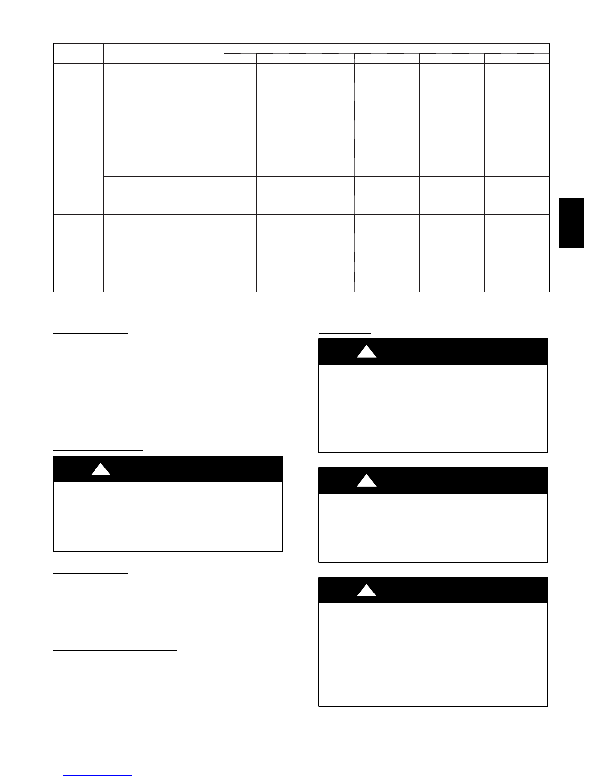
Table 5 -- Air Delivery -- CFM (With Filter)* (Cont.)
FURNACE
SIZE
135--- 16/
048135
135--- 22/
066135
155--- 20/
060155
*A filter is r equired for each return --- air inlet. Airflow performance included 3/4 - --in. (19 mm) washable filter media such as contained in factory ---authorized accessory filter rack. To determine airflow performance without this filter, assume an additional 0.1 In. W.C. available external static pressure.
------ Indicates unstable operating conditions.
RETURN---AIR
INLET
Bottom
or
Side(s)
Bottom
Only
Bottom Sides
or
1 Side & Bottom
1SideOnly
Bottom Only
Both Sides O r 1
Side & Bottom
1SideOnly
SPEED
High
M e d --- H i g h
M e d --- L o w
Low
High
M e d --- H i g h
M e d --- L o w
Low
High
M e d --- H i g h
M e d --- L o w
Low
High
M e d --- H i g h
M e d --- L o w
Low
High
M e d --- H i g h
M e d --- L o w
Low
High
M e d --- H i g h
High
M e d --- H i g h
0.1 0.2 0.3 0.4 0.5 0.6 0.7 0.8 0.9 1.0
2090
1790
1545
1325
2485
2195
1880
1640
--- --2180
1880
1640
2320
2125
1845
1640
2465
2115
1800
1570
--- --2155
--- --2140
2010
1755
1525
1320
2400
2150
1850
1635
--- --2145
1850
1635
2250
2065
1825
1620
2430
2105
1790
1565
--- --2135
--- --2095
Downflow Furnaces
EXTERNAL STATIC PRESSURE (IN. W.C.)
1930
1705
1500
1295
2310
2090
1820
1615
2385
2060
1820
1615
2155
1995
1765
1580
2375
2075
1770
1550
2375
2095
2260
2040
1835
1640
1450
1265
2215
2000
1780
1585
2305
2010
1780
1585
2055
1910
1710
1540
2305
2030
1735
1525
2285
2040
2180
1975
GAS
1710
1550
1380
1210
2110
1920
1715
1530
2195
1945
1715
1530
1970
1815
1650
1485
2230
1980
1695
1495
2200
1975
2085
1890
PIPING
1590
1465
1315
1150
2000
1825
1635
1465
2085
1865
1635
1465
1855
1710
1570
1410
2110
1910
1640
1445
2105
1895
1975
1810
1470
1360
1215
995
1880
1720
1540
1370
1960
1765
1540
1370
1725
1610
1475
1330
2000
1830
1570
1370
1995
1790
1865
1705
1335
1210
1005
865
1725
1565
1415
1255
1825
1660
1415
1255
1600
1490
1370
1220
1865
1725
1465
1270
1870
1685
1740
1595
1025
945
855
745
1535
1405
1290
1150
1670
1515
1290
1150
1450
1340
1240
1080
1725
1590
1345
1175
1730
1550
1605
1480
835
785
670
540
1355
1255
1160
1040
1465
1325
1160
1040
1280
1175
1100
960
1545
1425
1225
1070
1570
1400
1455
1325
Connect supply--air duct to supply--air outlet on furnace. Bend
flange inward past 90_ with wide duct pliers. (See Fig. 14.) The
supply--air duct must be connected to ONLY the furnace
supplyoutlet or air conditioning coil casing (when used). When
installed on combustible material, supply--air duct must be
connected to ONLY the factory--approved accessory subbase, or
a factory approved air conditioning coil casing. DO NOT cut
main furnace casing to attach supply side air duct, humidifier, or
other accessories. All accessories MUST be connected to duct
external to furnace casing.
Return Air
Connections
FIRE OR EXPLOSION HAZARD
Failure to follow this warning could result in personal
injury, death, and/or property damage.
Never purge a gas line into a combustion chamber. Never
test for gas leaks with an open flame. Use a commercially
available soap solution made specifically for the detection
of leaks to check all connections.
!
WARNING
312AAV
!
WARNING
FIRE HAZARD
Failure to follow this warning could cause personal injury,
death and/or property damage.
Never connect return--air ducts to the back of the furnace.
Follow instructions below.
Downflow Furnaces
The return--air duct must be connected to return--air opening
(bottom inlet) as shown in Fig. 1. DO NOT cut into casing sides
(left or right). Side opening is permitted for only upflow and most
horizontal furnaces. Bypass humidifier connections should be
made at ductwork or coil casing sides exterior to furnace. (See
Fig. 19.)
Upflow and Horizontal
Furnaces
The return--air duct must be connected to bottom, sides (left or
right), or a combination of bottom and side(s) of main furnace
casing as shown in Fig. 1. Bypass humidifier may be attached
into unused return air side of the furnace casing. (See Fig. 18 and
20.) Not all horizontal furnaces are approved for side return air
connections. (See Fig. 20.)
!
WARNING
FIRE OR EXPLOSION HAZARD
Failure to follow this warning could result in personal
injury, death, and/or property damage.
Use proper length of pipe to avoid stress on gas control
manifold and a gas leak.
!
WARNING
FIRE OR EXPLOSION HAZARD
Failure to protect gas valve inlet from water and debris
could result in death, personal injury and/or property
damage.
Gas valve inlet and/or inlet pipe must remain capped until
gas supply line is permanently installed to protect the valve
from moisture and debris. Also, install a sediment trap in the
gas supply piping at the inlet to the gas valve.
17
 Loading...