

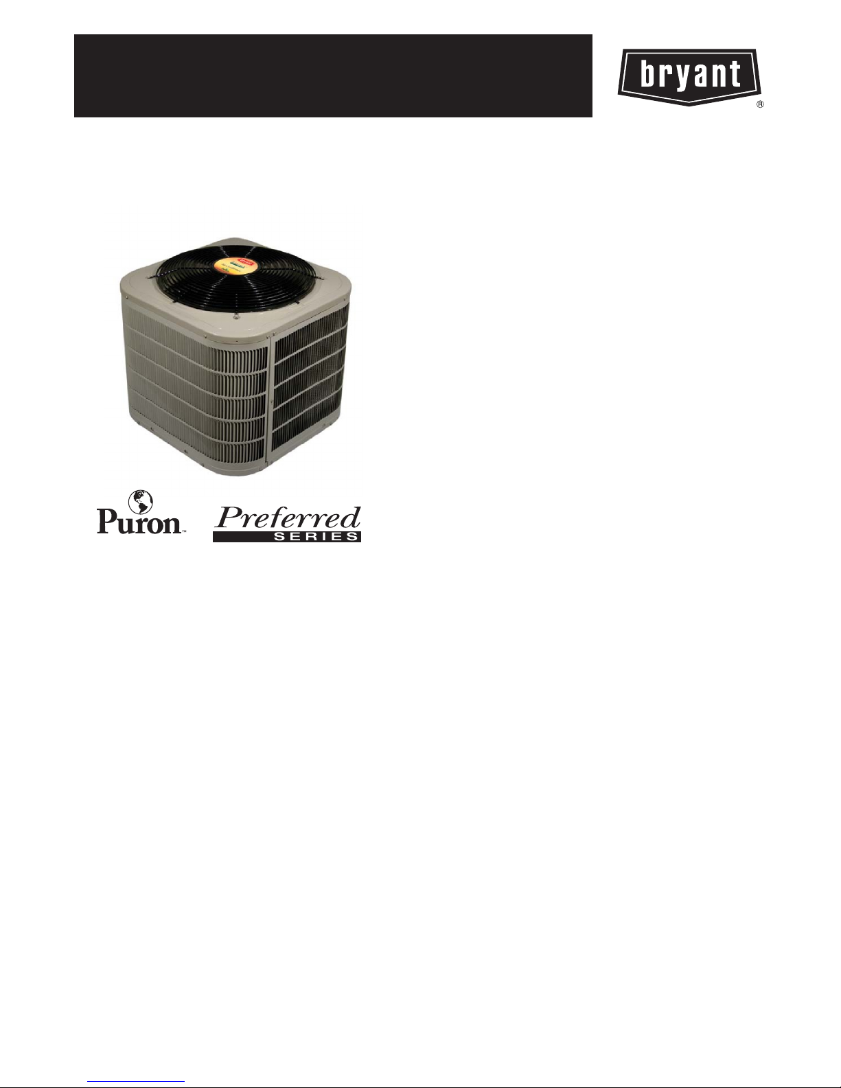
MODEL 126B
PREFERRED SERIES AIR CONDITIONER
WITH PURONREFRIGERANT
1--1/2 TO 5 NOMINAL TONS
Product Data
TM
the environmentally sound refrigerant
Bryant Air Conditioners with Puron r refrigerant provide a
collection of features unmatched by any other family of
equipment. The 126B has been designed utilizing Bryant’s Puron
refrigerant. The environmentally sound refrigerant allows you to
make a responsible decision in the protection of the earth’s ozone
layer.
As an Energy Starr Partner, Bryant Heating & Cooling has
determined that this product meets the Energy Starr guidelines
for energy efficiency. Refer to the combination ratings in the
Product Data for system combinations that meet Energy Starr
guidelines.
NOTE: Ratings contained in this document are subject to
change at any time. Always refer to the AHRI directory
(www.ahridirectory.org) for the most up--to--date ratings
information.
INDUSTRY LEADING
FEATURES / BENEFITS
Efficiency
14 -- 16.5 SEER / 11.5-- 13.5 EER
S
S Microtube Technologyt refrigeration system
S Indoor air quality accessories available
Sound
Sound level as low as 72 dBA
S
S Compressor sound blanket standard
Comfort
System supports Edger Thermidistatt or standard
S
thermostat controls
Reliability
Puronr refrigerant -- environmentally sound, won’t
S
deplete the ozone layer and low lifetime servce cost.
S Scroll compressor
S Internal pressure relief valve
S Internal thermal overload
S Filter drier
S High and low pressure switches
S Balanced refrigeration system for maximum reliability
Durability
DuraGuardt protection package:
S Solid, durable sheet metal construction
S Louvered coil guard
S Baked--on, complete outer coverage, powder paint
Applications
Long--line -- up to 250 feet (76.20 m) total equivalent
S
length, up to 200 feet (60.96 m) condenser above
evaporator, or up to 80 ft. (24.38 m) evaporator above
condenser (See Longline Guide for more information.)
S Low ambient (down to --20_F/--28.9_C)) with
accessory kit
MODEL NUMBER NOMENCLATURE
1 2 3 4 5 6 7 8 9 10111214
NNNAA/NNNNNA/NA/NNA
126B N A036000A
Product
Famil y
1=AC 2=
Tier SEER Major
Legacy
6=16
SEER
B=Puron N=
Series
Voltage Variation s Coolin g Capacity Open Open Open Minor
208---230--- 1
or
A=
Standard
0=
Not
Defined
0=
Not
Defined
0=
Not
Defined
208/230---1
ISO 9001:2000
126B
the environmentally sound refrigerant
Use of the AHRI Certified
TM Mark indicates a
manufacturer’s
participation in the
program For verification
of certification for individual
products, go to
www.ahridirectory.org.
REGISTERED
This product has been desi gned and manufactu red to
meet Energy St ar criteria for energy effi ciency when
matched wit h appropriate coil components. However,
proper refrigerant charge and proper ai r f low ar e cri tical
to achieve rated capacity and effici ency. Installation of
this product should follow all manufacturing refrigerant
charging and air flow instructions. Failure to confirm
proper charge and air flow may reduce energy
efficiency and shorten equipment life.
STANDARD FEATURES
Feature 018 024 030 036 042 048 060
Puron Refrigerant X X X X X X X
Maximum SEER * 16.0 16.0 16.5 16.5 16.0 16.0 16.0
Scroll Compressor X X X X X X X
FieldInstalledFilterDrier X X X X X X X
Fron t Seat ing Service Va lves X X X X X X X
Internal Pressure Relief Valve X X X X X X X
Internal Thermal Overload X X X X X X X
Long Line capability X X X X X X X
Low Ambient capability with Kit X X X X X X X
High Pressure Switch X X X X X X X
Low Pressure Switch X X X X X X X
Compressor Sound Blan ket X X X X X X X
Louvered Coil Guard X X X X X X X
* With approved combinations
X=Standard
Series
A=
Original
Series
UNIT SIZE ---VOLTAGE, SERIES 0018---A 024---A 030 --- A 036 --- A 042---A 048---A 060 ---A
Operating Weight lb (kg) 136 (61.7) 163 (73.9) 167 (75.7) 180 (81.6) 234 (106.1) 248 (112.5) 337 (152.9)
Shipping Weight lb (kg) 163 (73.9) 198 (89.8) 204 (92.5) 219 (99.3) 281 (127.5) 291 (132.0) 372 (188.7)
Compressor Ty p e Scroll
REFRIGERANT Puron (R --- 410A)
Control TXV (Puron Hard Shutoff)
Charge lb (kg) 4.60 (2.09) 6.00 (2.72) 6.81 (3.09) 7.00 (3.18) 8.62 (3.91) 10.50 (4.76) 14.50 (6.58)
COND FAN Propeller Type, Direct Drive
Air Discharge Vertical Vertical
Air Qty (CFM) 1881 2614 2614 3223 3810 4046 4046
Motor HP 1/12 1/10 1/10 1/12 1/5 1/4 1/4
Motor RPM 1100 800 800 800 800 800 800
COND COIL
Face Area (Sq ft) 11.50 15.10 17.20 17.60 25.15 20.10 30.15
Fins per In. 25 25 25 25 25 20 20
Rows 1 1 1 1 1 2 2
Circuits 3 4 4 4 6 7 8
VALVECONNECT.(In.ID)
Vapor 3/4 3/4 3/4 7/8 7/8 7/8 7/8
Liquid 3/8 3/8 3/8 3/8 3/8 3/8 3/8
REFRIGERANT TUBES (In. OD)
Rated Vapor* 3/4 7/8 11/8
Max Liquid Line 3/8 3/8
* Units are rated with 25 ft (7.6 m) of lineset length. See Vapor Line Sizing and Cooling Capacity Loss table when using other sizes and lengths of lineset.
Note: See unit Installation Instruction for proper installation.
{ See Liquid Line Sizing For Cooling Only Systems with Puron Refrigerant tables.
PHYSICAL DATA
2
REFRIGERANT PIPING LENGTH LIMITATIONS
Liquid Line Sizing and Maximum Total Equivalent Lengths
The maximum allowable length of a residential split system depends on the liquid line diameter and vertical separation between indoor and
outdoor units.
See Table below for liquid line sizing and maximum lengths :
Maximum Total Equivalent Length
Outdoor Unit BELOW Indoor Unit
Liquid
Size
18000
AC with
Puron
24000
AC with
Puron
30000
AC with
Puron
36000
AC with
Puron
42000
AC with
Puron
48000
AC with
Puron
60000
AC with
Puron
* Maximum actual length not to exce ed 200 ft (61 m)
{ Total equivalent length accounts for losses due to elbows or fitting. See the Long Line Guideline for details.
--- --- = o u t s i d e a c c e p t a b l e r a n g e
Liquid Line
Connection
3/8
3/8
3/8
3/8
3/8
3/8 3/8 250* 250* 250* 250* 250* 250* 230 160 --- ---
3/8 3/8 250* 250* 250* 225* 190 150 110 --- --- --- ---
Line
Diam.
w/ TXV
1/4 150 150 125 100 100 75 --- --- --- --- --- --5/16 250* 250* 250* 250* 250* 250* 250* 225* 150
3/8 250* 250* 250* 250* 250* 250* 250* 250* 250*
5/16 250* 250* 250* 250* 250* 225* 175 125 100
3/8 250* 250* 250* 250* 250* 250* 250* 250* 250*
1/4 30 --- --- --- --- --- --- --- --- --- --- --- --- --- --- --- --5/16 175 225* 200 175 125 100 75 --- --- --- --3/8 250* 250* 250* 250* 250* 250* 250* 250* 250*
5/16 175 150 150 100 100 100 75 --- --- --- ---
3//8 250* 250* 250* 250* 250* 250* 250* 250* 250*
5/16 125 100 100 75 75 50 --- --- --- --- --- ---
3/8 250* 250* 250* 250* 250* 250* 250* 250* 150
(0--- 1.5)
1/4 75 75 75 50 50 --- --- --- --- --- --- --- ---
AC with Puron Refrigerant Maximum Total Equivalent Length{: Outdoor unit BELOW Indoor
0 --- 5
6 --- 1 0
(1.8--- 3.0)
11--- 20
(3.4--- 6.1)
{
for Cooling Only Systems with Puronr Refrigerant:
Vertical Separation ft (m)
21--- 30
(6.4--- 9.1)
31--- 40
(9.4--- 12.2)
41--- 50
(12.5--- 15.2)
51--- 60
(15.5--- 18.3)
61--- 70
(18.6--- 21.3)
71--- 80
(21.6--- 24.4)
126B
Maximum Total Equivalent Length
Outdoor Unit ABOVE Indoor Unit
Liquid
Size
18000
AC with
Puron
24000
AC with
Puron
30000
AC with
Puron
36000
AC with
Puron
42000
AC with
Puron
48000
AC with
Puron
60000
AC with
Puron
* Maximum actual length not to exceed 200 ft (61 m)
{ Total equivalent length accounts for losses due to elbows or fitting. See the Long Line Guideline for details.
--- --- = o u t s i d e a c c e p t a b l e r a n g e
Liquid Line
Connection
3/8
3/8
3/8
3/8
3/8
3/8 3/8 250* 250* 250* 250* 250* 250* 250* 250*
3/8 3/8 250* 250* 250* 250* 250* 250* 250* 250*
Line
Diam.
w/ TXV
1/4 175 250* 250* 250* 250* 250* 250* 250*
5/16 250* 250* 250* 250* 250* 250* 250* 250*
3/8 250* 250* 250* 250* 250* 250* 250* 250*
1/4 100 125 175 200 225* 250* 250* 250*
5/16 250* 250* 250* 250* 250* 250* 250* 250*
3/8 250* 250* 250* 250* 250* 250* 250* 250*
1/4 30 --- --- --- --- --- --- --- --- --- --- --- --- --- --5/16 250* 250* 250* 250* 250* 250* 250* 250*
3/8 250* 250* 250* 250* 250* 250* 250* 250*
5/16 225* 250* 250* 250* 250* 250* 250* 250*
3/8 250* 250* 250* 250* 250* 250* 250* 250*
5/16 175 200 250* 250* 250* 250* 250* 250*
3/8 250* 250* 250* 250* 250* 250* 250* 250*
AC with Puron Refrigerant Maximum Total Equivalent Length{: Outdoor unit ABOVE Indoor
25
(7.6)
26--- 50
(7.9--- 15.2)
51--- 75
(15.5--- 22.9)
Vertical Separation ft (m)
76--- 100
(23.2--- 30.5)
101--- 125
(30.8--- 38.1)
126--- 150
(38.4--- 45.7)
151--- 175
(46.0--- 53.3)
176--- 200
(53.6--- 61.0)
3
REFRIGERANT CHARGE ADJUSTMENTS
Liquid Line Size Puron Charge oz/ft
3/8
5/16 0.40
1/4 0.27
(Factory charge for lineset = 9 oz)
0.60
Units are factory charged for 15 ft (4.6 m) of 3/8” liquid line. The factory charge for 3/8” lineset 9 oz. When using other length or diameter
liquid lines, charge adjustments are required per the chart above.
Charging
Formula:
[(Lineset oz/ft x total length) – (factory charge for lineset)] = charge adjustment
Example 1: System has 15 ft of line set using existing 1/4“ liquid line. What charge adjustment is required?
Formula: (.27 oz/ft x 15ft) – (9 oz) = (-4.95) oz.
Net result is to remove 4.95 oz of refrigerant from the system
Example 2: System has 45 ft of existing 5/16” liquid line. What is the charge adjustment?
Formula: (.40 oz/ft. x 45ft) – (9 oz.) = 9 oz.
Net result is to add 9 oz of refrigerant to the system
LONG LINE APPLICATIONS
An application is considered Long Line, when the refrigerant level in the system requires the use of accessories to maintain acceptable
126B
refrigerant management for systems reliability. See Accessory Usage Guideline table for required accessories. Defining a system as long line
depends on the liquid line diameter, actual length of the tubing, and vertical separation between the indoor and outdoor units.
For Air Conditioner systems, the chart below shows when an application is considered Long Line.
AC WITH PURONr REFRIGERANT LONG LINE DESCRIPTION ft (m)
Beyond these lengths, long line accessories are required
Liquid Line Size Units On Same Level Outdoor Below Indoor Outdoor Above Indoor
1/4
5/16 120 (36.6) 50 (15.2) 120 (36.6)
3/8 80 (24.4) 35 (10.7) 80 (24.4)
Note: SeeLongLineGuidelinefordetails
No accessories needed within allowed
lengths
No accessories needed within allowed
lengths
175 (53.3)
VAPOR LINE SIZING AND COOLING CAPACITY LOSS
Acceptable vapor line diameters provide adequate oil return to the compressor while avoiding excessive capacity loss. The suction line
diameters shown in the chart below are acceptable for AC systems with Puron refrigerant:
Unit
Nominal
Size (Btuh)
18000
1Stage
AC with
Puron
24000
1Stage
AC with
Puron
30000
1Stage
AC with
Puron
36000
1Stage
AC with
Puron
42000
1Stage
AC with
Puron
48000
1Stage
AC with
Puron
60000
1Stage
AC with
Puron
Applications in this area may be long line and may have height restriction s. See the Residential Piping and Long Line Guideline.
Maximum
Liquid Line
Diameters
(In. OD)
3/8
3/8
3/8
3/8
3/8
3/8
3/8
Vapo r Line
Diameters
(In. OD)
1/2 1 2 3 5 6 7 8 9 11
5/8 0 1 1 1 2 2 2 3 3
3/4 0 0 0 0 1 1 1 1 1
5/8 0 1 2 2 3 3 4 5 5
3/4 0 0 1 1 1 1 1 2 2
7/8 0 0 0 0 0 1 1 1 1
5/8 1 2 3 3 4 5 6 7 8
3/4 0 0 1 1 1 2 2 2 3
7/8 0 0 0 0 1 1 1 1 1
5/8 1 2 4 5 6 8 9 10 12
3/4 0 1 1 2 2 3 3 4 4
7/8 0 0 0 1 1 1 1 2 2
3/4 0 1 2 2 3 4 4 5 6
7/8 0 0 1 1 1 2 2 2 3
11/8 0 0 0 0 0 0 0 0 0
3/4 0 1 2 3 4 5 5 6 7
7/8 0 0 1 1 2 2 2 3 3
11/8 0 0 0 0 0 0 0 1 1
3/4 1 2 4 5 6 7 9 10 11
7/8 0 1 2 2 3 4 4 5 5
11/8 0 0 0 1 1 1 1 1 1
26---50
(7.9--- 15.2)
51---80
(15.5--- 24.4)
81---100
(24.7--- 30.5)
Cooling C apacity Loss (%)
Total Equivalent Line Le ngth ft. (m)
101---125
(30.8--- 38.1)
126---150
(38.4--- 45.7)
151---175
(46.0--- 53.3)
176---200
(53.6--- 61.0)
201---225
(61.3--- 68.6)
226---250
(68.9--- 76.2)
4
ACCESSORY THERMOSTATS
THERMOSTAT / SUBBASE
PKG.
T 6 --- P R H 0 1 --- A Programmable Thermidistat
T 6 --- N R H 0 1 --- A Non --- programmable Thermidistat
T 6 --- P A C 0 1 Preferred Series Programmable AC Stat
T 6 --- N A C 0 1 Preferred Series Non--- programmable AC Stat
T 2 --- P A C 0 1 Legacy Series Programmable AC Stat
T 2 --- N A C 0 1 Legacy Series Non--- programmable AC Stat
T 1 --- P A C 0 1 Legacy RNC Series Programmable AC Stat
T 1 --- N A C 0 1 Legacy RNC Series Non --- programmable AC Stat
TSTATBBSEN01---B Outdoor Air Temperature Sensor
TSTATXXBBP01 Backplate for Builder’s Thermostat
TSTATXXNBP01 Backplate for Non---Programmable Thermostat
TSTATXXPBP01 Backplate for Programmable Thermostat
TSTATXXCNV10 Thermostat Conversion Kit (4 to 5 wires) - -- 10 Pack
DESCRIPTION
ACCESSORIES
KIT NUMBER DESCRIPTION
KAAFT0101AAA FREEZE THERMOSTAT X X X X X X X
KAATD0101TDR TIME DELAY RELAY X X X X X X X
KSALA0301410 LOW AMBIENT PSW X X X X X X X
KSALA0601AAA{ MOTORMASTER 230V X X X X X X X
HC32GE234 MOTOR FAN BALL BEARING X
HC34GE240 MOTOR FAN BALL BEARING X X
HC32GE229 MOTOR FAN BALL BEARING X
HC38GE228 MOTOR FAN BALL BEARING X
HC40GE228 MOTOR FAN BALL BEARING X X
KSAHS1701AAA HARD START (CAP/RELAY) X X X X X X X
KSACY0101AAA CYCLE PROTECTOR X X X X X X X
KSASF0101AAA SUPPORT FEET X X X X X X X
KAACS0201PTC STARTASSISTPTC X X X X X X X
KAALS0201LLS LIQUID LINE SOLENOID X X X X X X X
KAAWS0101AAA WINTER START X X X X X X X
KAACH1701AAA CRANKCASE HTR X X X X
KAACH1601AAA CRANKCASE HTR X S S
KSATX0201PUR TXV PURON HSO X X X
KSATX0301PUR TXV PURON HSO X
KSATX0401PUR TXV PURON HSO X
KSATX0501PUR TXV PURON HSO X X
{ Required accessories include ball bearing fan motor, compressor start assist (CAP / Relay), crankcase heater, evaporator freeze stat, hard shut ---off TXV.
X = Accessory / S --- Standard
0018---A 024- --A 030 --- A 036--- A 042 --- A 048 --- A 060- -- A
Size -- - Voltage & Series
126B
5

ACCESSORY USAGE GUIDELINE
REQUIRED FOR LOW---AMBI-
ACCESSORY
Ball Bearing Fan Motor Yes{ No No
Compressor Start Assist Capacitor and Relay Yes Yes No
Crankcase Heater Yes Ye s No
Evaporator Freeze Thermostat Yes No No
H a r d S h u t --- O f f T X V Yes Yes Yes
Liquid Line Solenoid Valve No No No
Motor MasterControl or
L o w --- a m b i e n t P r e s s ur e S w i t c h
Support Feet Recommended No Recommended
* For tubing line sets between 80 and 200 ft. (24.38 and 60.96 m) and/or 20 ft. (6.09 m) vertical differential, refer to Residential Split---System Longline
Application Guideline.
{ Required for Low--- Ambient Controller (full modulation feature) MotorMasterr Control.
Winter Start Control Yes No No
ENT COOLING APPLICATIONS
(Below 55F/12.8_C)
Yes No No
Accessory Description and Usage (Listed Alphabetically)
1. Ball--Bearing Fan Motor
126B
A fan motor with ball bearings which permits speed reduction
while maintaining bearing lubrication.
Usage Guideline:
Required on all units when MotorMasterr is used.
2. Compressor Start Assist -- Capacitor and Relay
Start capacitor and relay gives a ”hard” boost to compressor
motor at each start up.
Usage Guideline:
Required for reciprocating compressors in the
following applications:
Long line
Low ambient cooling
Hard shut off expansion valve on indoor coil
Liquid line solenoid on indoor coil
Required for single--phase scroll compressors in the
following applications:
Long line
Low ambient cooling
Suggested for all compressors in areas with a history of
low voltage problems.
3. Compressor Start Assist — PTC Type
Solid state electrical device which gives a ”soft” boost to the
compressor at each start--up.
Usage Guideline:
Suggested in installations with marginal power supply.
4. Crankcase Heater
An electric resistance heater which mounts to the base of the
compressor to keep the lubricant warm during off cycles.
Improves compressor lubrication on restart and minimizes the
chance of liquid slugging.
Usage Guideline:
Required in low ambient cooling applications.
Required in long line applications.
Suggested in all commercial applications.
5. Cycle Protector
The cycle protector is designed to prevent compressor short
cycling. This control provides an approximate 5--minute delay
after power to the compressor has been interrupted for any
reason, including power outage, protector control trip, thermostat
jiggling, or normal cycling.
6. Evaporator Freeze Thermostat
An SPST temperature--actuated switch that stops unit operation
when evaporator reaches freeze--up conditions.
7. Low--Ambient Pressure Switch Kit
A long life pressure switch which is mounted to outdoor unit
service valve. It is designed to cycle the outdoor fan motor in
order to maintain head pressure within normal operating limits
(approximately 100 psig to 225 psig). The control will maintain
working head pressure at low--ambient temperatures down to 0_F
(--18_C) when properly installed.
Low--Ambient Controller must be used when cooling operation is
used at outdoor temperatures below 55_F (12.8_C).
8. MotorMasterr Low--Ambient Controller
A fan--speed control device activated by a temperature sensor,
designed to control condenser fan motor speed in response to the
saturated, condensing temperature during operation in cooling
mode only. For outdoor temperatures down to --20_F (--28.9_C),
it maintains condensing temperature at 100_F 10_F (37.8_C
5.5_C).
9. Outdoor Air Temperature Sensor
Designed for use with Bryant Thermostats listed in this
publication. This device enables the thermostat to display the
outdoor temperature. This device also
is required to enable special thermostat features such as auxiliary
heat lock out.
REQUIRED FOR LONG
LINE
APPLICATIONS*
(Over 80 ft./24.38 m)
(Within2miles/3.22km)
Usage Guideline:
Required when low ambient kit has been added.
Usage Guideline:
A Low--Ambient Pressure Switch or MotorMasterr
Usage Guideline:
A MotorMasterr Low Ambient Controller or
Low--Ambient Pressure Switch must be used when
cooling operation is used at outdoor temperatures
below 55_F (12.8_C).
Suggested for all commercial applications.
Usage Guideline:
Suggested for all Bryant thermostats listed in this
publication.
REQUIRED FOR
SEA COAST
APPLICATIONS
6

Accessory Description and Usage (Listed Alphabetically) (Continued)
10. Support Feet
Four stick--on plastic feet that raise the unit 4 in. (101.6 mm)
above the mounting pad. This allows sand, dirt, and other debris
to be flushed from the unit base, minimizing corrosion.
Usage Guideline:
Suggested in the following applications:
Coastal installations.
Windy areas or where debris is normally circulating.
Rooftop installations.
For improved sound ratings.
11. Thermostatic Expansion Valve (TXV)
A modulating flow--control valve which meters refrigerant liquid
flow rate into the evaporator in response to the superheat of the
refrigerant gas leaving the evaporator.
Kit includes valve, adapter tubes, and external equalizer tube.
Hard shut off types are available.
NOTE: When using a hard shut off TXV with single phase
reciprocating compressors, a Compressor Start Assist Capacitor
and Relay is required.
Usage Guideline:
Required to achieve AHRI ratings in certain equipment
combinations. Refer to combination ratings.
Hard shut off TXV or LLS required in air conditioner
long line applications.
Required for use on all zoning systems.
12. Time--Delay Relay
An SPST delay relay which briefly continues operation of indoor
blower motor to provide additional cooling after the compressor
cycles off.
NOTE: Most indoor unit controls include this feature. For those
that do not, use the guideline below.
Usage Guideline:
For improved efficiency ratings for certain
combinations of indoor and outdoor units. Refer to
AHRI Unitary Directory.
13. Winter Start Control
This control is designed to alleviate nuisance opening of the
low--pressure switch by bypassing it for the first 3 minutes of
operation.
126B
7
ELECTRICAL DATA
UNIT SIZE V/PH
018---A
024---A 58.3 13.5 0.70 17.6 14 14 46 (14.0) 43 (13..1) 25
030---A 64.0 12.8 0.70 16.7 14 14 44 (13.4) 41 (12.5) 25
036---A 77.0 14.1 0.50 18.1 12 12 57 (17.4) 54 (16.5) 30
042---A 112.0 17.9 1.20 23.6 10 10 85 (25.9) 81 (24.7) 40
048---A 109.0 19.9 1.20 26.1 10 10 70 (21.3) 67 (20.4) 40
060---A 208/ 230/ 1 ---60 253 197 135.0 21.4 1.20 28.0 8 10 91 (27.7) 56 (17.1) 40
* Permissible limits of the voltage range at which the unit will operate satisfactorily
{ If wire is applied at ambient greater than 30_C, consult table 310--- 16 of the NEC (NFPA 70). The ampacity of non --- metallic--- sheathed cable (NM), trade
name ROMEX, shall be that of 60_C conditions, per the NEC (NFPA 70) Article 336---26. If other than uncoated (no---plated), 60 or 75_C insulation, copper
wire (solid wire for 10 AWG or smaller, stranded wire for larger than 10 AWG) is used, consult applicable tables of the NEC (NFPA 70).
} Length shown is as measured one way along wire path between unit and service panel for voltage drop not to exceed 2%.
* * T i m e --- D el a y fu se .
FLA --- Fu l l L o a d A m p s
LRA --- Lo c k e d R o t o r A m p s
MCA --- Minimu m Circuit Amps
RLA ---RatedLoadAmps
NOTE: Control circuit is 24 --- V on all units and requires external power source. Copper wire must be used from service disconnect to unit.
All motors/compressors contain internal overload protection.
Complies with 2007 requirements of ASHRAE Standards 90.1
208/230/1--- 60 253 197
OPER VOLTS* COMPR FAN
MAX MIN LRA RLA FLA
48.0 9.0 0.50 11.8 14 14 67 (20.4) 64 (19.5) 20
MCA
MIN WIRE
SIZE{
60 C
MIN WIRE
SIZE{
75 C
MAX
LENGTH
ft. (m)}
60 C
126B
MAX
LENGTH
ft. (m)}
75 C
A--WEIGHTED SOUND POWER LEVEL (dBA)
U n i t S i z e ---
Voltage, Series
018---A 73 49.5 58.5 64.5 69.0 63.0 59.5 52.4
024---A 74 54.5 62.0 67.0 71.5 66.0 62.0 53.0
030---A 74 56.0 62.5 66.0 68.5 64.5 61.0 53.5
036---A 72 52.0 61.0 64.0 66.0 61.0 58.5 51.5
042---A 74 56.5 61.5 65.0 66.5 63.5 61.0 56.5
048---A 73 58.0 61.0 65.0 66.0 62.0 58.0 51.0
060---A 74 56.5 62.5 66.5 68.0 63.0 59.5 51.5
NOTE: Tested in accordance with AHRI Standard 270 ---08 (not listed in AHRI).
Standard
Rating (dBA)
125 250 500 1000 2000 4000 8000
TYPICAL OCTAVE BAND SPECTRUM (dBA without tone adjustment)
MAX FUSE**
or CKT BRK
AMPS
CHARGING SUBCOOLING (TXV--TYPE EXPANSION DEVICE)
UNIT SIZE ---VOLTAGE, SERIES REQUIRED SUBCOOLING _F(_C)
018---A 10 (5.6)
024---A 10 (5.6)
030---A 10 (5.6)
036---A 10 (5.6)
042---A 9 (5.0)
048---A 10 (5.6)
060---A 9 (5.0)
8
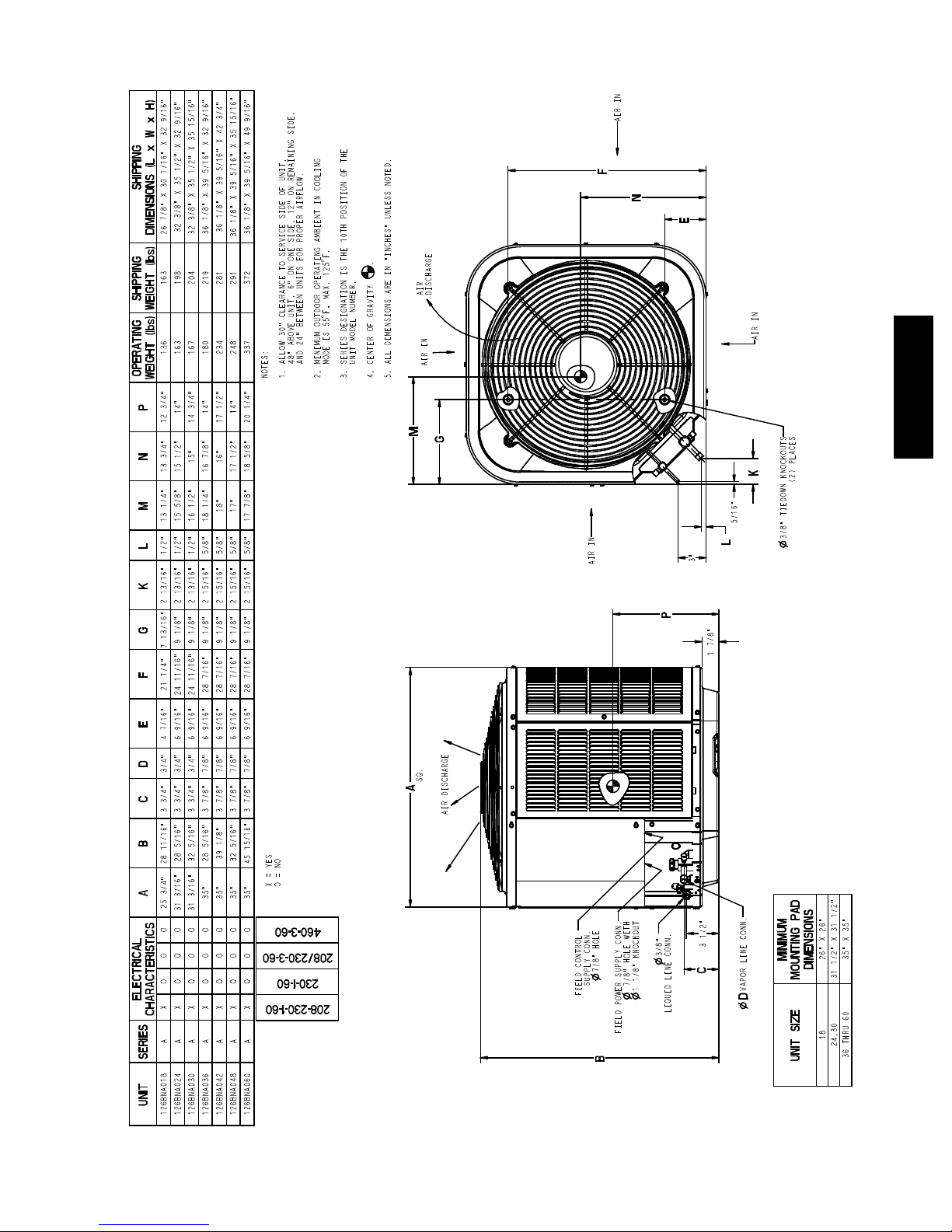
SHIPPING
SHIPPING
OPERATING
AIR IN
F
N
E
AIR
WEIGHT (lbs)
WEIGHT (lbs)
NOTES:
F, MAX. 125
48" ABOVE UN IT, 6" ON ONE SIDE, 12" ON REMAINING SIDE,
AND 24" BETWEEN UNITS FOR PROPER AIRFLOW.
1. ALLOW 3 0" CLEARANCE TO SERVICE SIDE OF UNIT,
MODE IS 55
2. MINIMUM OUTDOOR OPERATING AMBIENT IN COOLING
DISCHARGE
AIR IN
AIR IN
126B
M
G
K
(2) PLACES
5/16"
L
AIR IN
3"
ABCDEFGKLMNP
ELECTRICAL
CHARACTERISTICS
A X O O O 25 3/4" 28 11/16" 3 3/4" 3/4" 4 7/16" 21 1/4" 7 13/16" 2 13/16" 1/2" 13 1/4" 13 3/4" 12 3/4" 136 163
A X O O O 31 3/16" 28 5/16" 3 3/4" 3/4" 6 9/16" 24 11/16" 9 1/8" 2 13/16" 1/2" 15 5/8" 15 1/2" 14" 163 198
A X O O O 31 3/16" 32 5/16" 3 3/4" 3/4" 6 9/16" 24 11/16" 9 1/8" 2 13/16" 1/2" 16 1/2" 15" 14 3/4" 167 204
A X O O O 35" 28 5/16" 3 7/8" 7/8" 6 9/16" 28 7/16" 9 1/8" 2 15/16" 5/8" 18 1/4" 16 7/8" 14" 180 219
A X O O O 35" 39 1/8" 3 7/8" 7/8" 6 9/16" 28 7/16" 9 1/8" 2 15/16" 5/8" 18" 16" 17 1/2" 234 281
A X O O O 35" 32 5/16" 3 7/8" 7/8" 6 9/16" 28 7/16" 9 1/8" 2 15/16" 5/8" 17" 17 1/2" 14" 248 291
A X O O O 35" 45 15/16" 3 7/8" 7/8" 6 9/16" 28 7/16" 9 1/8" 2 15/16" 5/8" 17 7/8" 18 5/8" 20 1/4" 337 372
X = YES
P
17/8"
SQ.
A
AIR DISCHARGE
O=NO
460-3-60
208/230-3-60
230-1-60
208-230-1-60
7/8" HOLE
SUPPLY CONN.
7/8" HOLE WITH
FIELD CONTROL
1 1/8" KNOCKOUT
31/2"
C
D
18 26" X 26"
24,30
B
UNIT SERIES
DIMENSIONS -- ENGLISH
9
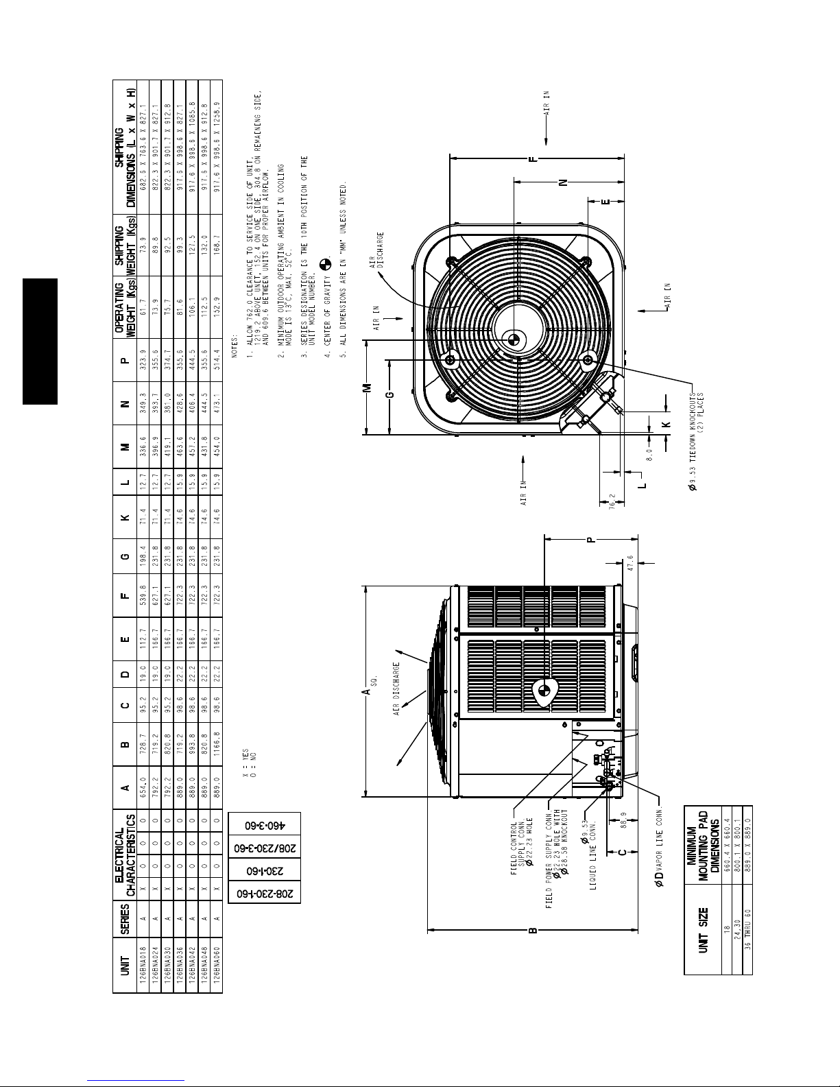
AIR IN
126B
SHIPPING
SHIPPING
OPERATING
F
N
DIMENSIONS (L x W x H)
AIR
WEIGHT (Kgs)
C, MAX. 52
WEIGHT (Kgs)
DISCHARGE
AIR IN
M
G
AIR IN
E
AIR IN
K
(2) PLACES
8.0
L
76.2
9.53 TIEDOWN KNOCKOUTS
P
ABCDEFGKLMNP
ELECTRICAL
CHARACTERISTICS
UNIT SERIES
126BNA018 A X O O O 654.0 728.7 95.2 19.0 112.7 539.8 198.4 71.4 12.7 336.6 349.3 323.9 61.7 73.9 682.6 X 763.6 X 827.1
47.6
SQ.
A
AIR DISCHARGE
X = YES
O=NO
460-3-60
88.9
208/230-3-60
230-1-60
208-230-1-60
22.23 HOLE
SUPPLY CONN.
FIELD CONTROL
28.58 KNOCKOUT
22.23 HOLE WITH
FIELD POWER SUPPLY CONN.
B
126BNA024 A X O O O 792.2 719.2 95.2 19.0 166.7 627.1 231.8 71.4 12.7 396.9 393.7 355.6 73.9 89.8 822.3 X 901.7 X827.1
126BNA030 A X O O O 792.2 820.8 95.2 19.0 166.7 627.1 231.8 71.4 12.7 419.1 381.0 374.7 75.7 92.5 822.3 X 901.7 X912.8
126BNA036 A X O O O 889.0 719.2 98.6 22.2 166.7 722.3 231.8 74.6 15.9 463.6 428.6 355.6 81.6 99.3 917.6 X998.6 X 827.1
126BNA042 A X O O O 889.0 993.8 98.6 22.2 166.7 722.3 231.8 74.6 15.9 457.2 406.4 444.5 106.1 127.5 917.6 X 998.6 X 1085.8
126BNA048 A X O O O 889.0 820.8 98.6 22.2 166.7 722.3 231.8 74.6 15.9 431.8 444.5 355.6 112.5 132.0 917.6 X 998.6 X 912.8
126BNA060 A X O O O 889.0 1166.8 98.6 22.2 166.7 722.3 231.8 74.6 15.9 454.0 473.1 514.4 152.9 168.7 917.6 X 998.6 X 1258.9
C
MINIMUM
D
VAPOR LINE C ONN.
DIMENSIONS
MOUNTING PAD
UNIT SIZE
18 660.4 X 660.4
24,30 800.1 X 800.1
36 THRU 60 889.0 X 889.0
DIMENSIONS -- SI
10
Wall
6”
(152.4)
24”
Wall
Clearances (various examples)
Service
12”
(304.8)
6”
Wall
(152.4 mm)
12”
(304.8)
12”
(304.8)
12”
(304.8)
Wall
24”
(609.6)
24”
(609.6)
24”
(609.6)
Service
Service
Service
126B
24”
(609.6)
24”
(609.6)
CLEARANCES
24”
(609.6)
Service
11
24”
Note: Numbers in ( ) = mm
(609.6)
IMPORTANT: When installing multiple units in an alcove, roof well, or partially enclosed area, ensure there is adequate ventilation to prevent re--circulation of discharge air.

COMBINATION RATINGS
AHRI Ref. No. Model Number Indoor Model Furnace Model Capacity EER SEER
3658191 126BNA018****A †CNPV*1917A**+TDR 18,000 12.0 14.5
3657188 126BNA018****A CAP**1814A** 313*AV024045 18,000 13.0 15.5
3657187 126BNA018****A CAP**1814A** 315(A,J)AV036070 18,000 12.5 15.5
3657189 126BNA018****A CAP**1814A**+TDR 18,000 11.5 13.5
3657192 126BNA018****A CAP**2414A** 313*AV024045 18,000 13.0 16.0
3657190 126BNA018****A CAP**2414A** 315(A,J)AV036070 18,000 13.0 16.0
3657194 126BNA018****A CAP**2414A**+TDR 18,000 11.5 14.0
3657207 126BNA018****A CAP**2417A** 313*AV024045 18,000 13.0 16.0
3657196 126BNA018****A CAP**2417A** 315(A,J)AV036070 18,000 13.0 16.0
3657198 126BNA018****A CAP**2417A** 315(A,J)AV048090 18,000 13.0 16.0
3657200 126BNA018****A CAP**2417A** 353(A,B)AV036060 18,000 13.0 16.0
3657203 126BNA018****A CAP**2417A** 353AAV036040 18,000 13.0 16.0
3657205 126BNA018****A CAP**2417A** 355(A,C)AV042060 18,000 13.0 16.0
3657213 126BNA018****A CAP**2417A** 355BAV042060 18,000 13.0 16.0
3657209 126BNA018****A CAP**2417A** 368RAN036105 18,000 13.0 16.0
3657211 126BNA018****A CAP**2417A** 374RAN036105 18,000 13.0 16.0
3657215 126BNA018****A CAP**2417A**+TDR 18,000 11.5 14.0
3657693 126BNA018****A CNPF*2418A**+TDR 18,000 11.5 14.0
3657722 126BNA018****A CNPH*2417A** 313*AV024045 18,000 13.0 16.0
3657701 126BNA018****A CNPH*2417A** 315(A,J)AV036070 18,000 13.0 16.0
3657703 126BNA018****A CNPH*2417A** 315(A,J)AV048090 18,000 13.0 16.0
3657708 126BNA018****A CNPH*2417A** 353(A,B)AV036060 18,000 13.0 16.0
3657711 126BNA018****A CNPH*2417A** 353AAV036040 18,000 13.0 16.0
126B
3657713 126BNA018****A CNPH*2417A** 355(A,C)AV042060 18,000 13.0 16.0
3657715 126BNA018****A CNPH*2417A** 355(A,C)AV042080 18,000 13.0 16.0
3657720 126BNA018****A CNPH*2417A** 355AAV042040 18,000 13.0 16.0
3657728 126BNA018****A CNPH*2417A** 355BAV042060 18,000 13.0 16.0
3657730 126BNA018****A CNPH*2417A** 355BAV042080 18,000 13.0 16.0
3657724 126BNA018****A CNPH*2417A** 368RAN036105 18,000 13.0 16.0
3657726 126BNA018****A CNPH*2417A** 374RAN036105 18,000 13.0 16.0
3657735 126BNA018****A CNPH*2417A**+TDR 18,000 12.0 14.5
3658173 126BNA018****A CNPV*1814A** 313*AV024045 18,000 13.0 15.5
3658172 126BNA018****A CNPV*1814A** 315(A,J)AV036070 18,000 13.0 15.5
3658174 126BNA018****A CNPV*1814A**+TDR 18,000 11.5 14.0
3658185 126BNA018****A CNPV*1917A** 313*AV024045 18,000 13.0 16.0
3658175 126BNA018****A CNPV*1917A** 315(A,J)AV036070 18,000 13.0 16.0
3658177 126BNA018****A CNPV*1917A** 315(A,J)AV048090 18,000 13.0 16.0
3658179 126BNA018****A CNPV*1917A** 353(A,B)AV036060 18,000 13.0 16.0
3658181 126BNA018****A CNPV*1917A** 353AAV036040 18,000 13.0 16.0
3658183 126BNA018****A CNPV*1917A** 355(A,C)AV042060 18,000 13.0 16.0
3658189 126BNA018****A CNPV*1917A** 355BAV042060 18,000 13.0 16.0
3658187 126BNA018****A CNPV*1917A** 368RAN036105 18,000 13.0 16.0
3658188 126BNA018****A CNPV*1917A** 374RAN036105 18,000 13.0 16.0
3658195 126BNA018****A CNPV*2414A** 313*AV024045 18,000 13.0 16.0
3658193 126BNA018****A CNPV*2414A** 315(A,J)AV036070 18,000 13.0 16.0
3658197 126BNA018****A CNPV*2414A**+TDR 18,000 11.5 14.0
3658210 126BNA018****A CNPV*2417A** 313*AV024045 18,000 13.0 16.0
3658199 126BNA018****A CNPV*2417A** 315(A,J)AV036070 18,000 13.0 16.0
3658201 126BNA018****A CNPV*2417A** 315(A,J)AV048090 18,000 13.0 16.0
3658203 126BNA018****A CNPV*2417A** 353(A,B)AV036060 18,000 13.0 16.0
3658206 126BNA018****A CNPV*2417A** 353AAV036040 18,000 13.0 16.0
3658208 126BNA018****A CNPV*2417A** 355(A,C)AV042060 18,000 13.0 16.0
3658216 126BNA018****A CNPV*2417A** 355BAV042060 18,000 13.0 16.0
3658212 126BNA018****A CNPV*2417A** 368RAN036105 18,000 13.0 16.0
3658214 126BNA018****A CNPV*2417A** 374RAN036105 18,000 13.0 16.0
3658218 126BNA018****A CNPV*2417A**+TDR 18,000 11.5 14.0
3658673 126BNA018****A CSPH*2412A** 313*AV024045 18,000 13.0 16.0
3658662 126BNA018****A CSPH*2412A** 315(A,J)AV036070 18,000 13.0 16.0
3658663 126BNA018****A CSPH*2412A** 315(A,J)AV048090 18,000 13.0 16.0
3658668 126BNA018****A CSPH*2412A** 353(A,B)AV036060 18,000 13.0 16.0
3658669 126BNA018****A CSPH*2412A** 353AAV036040 18,000 13.0 16.0
3658670 126BNA018****A CSPH*2412A** 355(A,C)AV042060 18,000 13.0 16.0
3658671 126BNA018****A CSPH*2412A** 355(A,C)AV042080 18,000 13.0 16.0
3658672 126BNA018****A CSPH*2412A** 355AAV042040 18,000 13.0 16.0
3658678 126BNA018****A CSPH*2412A** 355BAV042060 18,000 13.0 16.0
3658679 126BNA018****A CSPH*2412A** 355BAV042080 18,000 13.0 16.0
3658664 126BNA018****A CSPH*2412A** 359BAV036040 18,000 13.0 15.5
3658666 126BNA018****A CSPH*2412A** 359BAV036060 18,000 13.0 15.5
3658674 126BNA018****A CSPH*2412A** 368RAN036105 18,000 13.0 16.0
3658676 126BNA018****A CSPH*2412A** 374RAN036105 18,000 13.0 16.0
3658680 126BNA018****A CSPH*2412A**+TDR 18,000 12.0 14.0
3659049 126BNA018****A FE4ANF002+UI 18,000 13.0 16.0
3659056 126BNA018****A FF1ENP018 18,000 11.5 14.0
3659057 126BNA018****A FF1ENP019 18,000 12.5 15.5
3659058 126BNA018****A FF1ENP024 18,000 11.5 14.0
3659060 126BNA018****A FF1ENP025 18,000 13.0 16.0
3659083 126BNA018****A FV4BNF002 18,000 13.0 16.0
3658269 126BNA024****A †CNPV*3117A**+TDR 23,600 12.0 14.5
See notes on page 37
12

COMBINATION RATINGS CONTINUED
AHRI Ref. No. Model Number Indoor Model Furnace Model Capacity EER SEER
3657193 126BNA024****A CAP**2414A** 313*AV024045 23,000 12.5 15.5
3657191 126BNA024****A CAP**2414A** 315(A,J)AV036070 22,800 12.5 15.5
3657195 126BNA024****A CAP**2414A**+TDR 23,000 11.5 14.0
3657202 126BNA024****A CAP**2417A** 353(A,B)AV036080 23,200 13.0 16.0
3657208 126BNA024****A CAP**2417A** 313*AV024045 23,000 12.5 15.5
3657197 126BNA024****A CAP**2417A** 315(A,J)AV036070 22,800 12.5 15.5
3657199 126BNA024****A CAP**2417A** 315(A,J)AV048090 22,800 13.0 16.0
3657201 126BNA024****A CAP**2417A** 353(A,B)AV036060 23,400 13.0 16.0
3657204 126BNA024****A CAP**2417A** 353AAV036040 23,400 13.0 16.0
3657206 126BNA024****A CAP**2417A** 355(A,C)AV042060 23,200 13.0 16.0
3657214 126BNA024****A CAP**2417A** 355BAV042060 23,200 13.0 16.0
3657210 126BNA024****A CAP**2417A** 368RAN036105 23,000 13.0 16.0
3657212 126BNA024****A CAP**2417A** 374RAN036105 22,800 13.0 15.5
3657216 126BNA024****A CAP**2417A**+TDR 23,000 11.5 14.0
3657219 126BNA024****A CAP**3014A** 313*AV024045 23,200 12.5 15.5
3657217 126BNA024****A CAP**3014A** 315(A,J)AV036070 22,800 13.0 16.0
3657220 126BNA024****A CAP**3014A**+TDR 23,200 11.5 14.0
3657228 126BNA024****A CAP**3017A** 353(A,B)AV036080 23,400 13.0 16.0
3657235 126BNA024****A CAP**3017A** 313*AV024045 23,200 13.0 16.0
3657222 126BNA024****A CAP**3017A** 315(A,J)AV036070 23,000 13.0 16.0
3657224 126BNA024****A CAP**3017A** 315(A,J)AV048090 23,000 13.0 16.0
3657226 126BNA024****A CAP**3017A** 353(A,B)AV036060 23,600 13.0 16.0
3657231 126BNA024****A CAP**3017A** 353AAV036040 23,600 13.0 16.0
3657233 126BNA024****A CAP**3017A** 355(A,C)AV042060 23,200 13.0 16.0
3657241 126BNA024****A CAP**3017A** 355BAV042060 23,200 13.0 16.0
3657237 126BNA024****A CAP**3017A** 368RAN036105 23,200 13.0 16.0
3657239 126BNA024****A CAP**3017A** 374RAN036105 23,000 13.0 16.0
3657243 126BNA024****A CAP**3017A**+TDR 23,200 11.5 14.0
3657248 126BNA024****A CAP**3614A** 313*AV024045 23,200 13.0 16.0
3657245 126BNA024****A CAP**3614A** 315(A,J)AV036070 23,000 13.0 16.0
3657250 126BNA024****A CAP**3614A**+TDR 23,200 11.5 14.0
3657262 126BNA024****A CAP**3617A** 353(A,B)AV036080 23,600 13.0 16.0
3657273 126BNA024****A CAP**3617A** 313*AV024045 23,400 13.0 16.0
3657253 126BNA024****A CAP**3617A** 315(A,J)AV036070 23,000 13.0 16.0
3657256 126BNA024****A CAP**3617A** 315(A,J)AV048090 23,000 13.0 16.0
3657259 126BNA024****A CAP**3617A** 353(A,B)AV036060 23,800 13.0 16.0
3657267 126BNA024****A CAP**3617A** 353AAV036040 23,600 13.0 16.0
3657270 126BNA024****A CAP**3617A** 355(A,C)AV042060 23,400 13.0 16.0
3657283 126BNA024****A CAP**3617A** 355BAV042060 23,400 13.0 16.0
3657277 126BNA024****A CAP**3617A** 368RAN036105 23,200 13.0 16.0
3657280 126BNA024****A CAP**3617A** 374RAN036105 23,000 13.0 16.0
3657286 126BNA024****A CAP**3617A**+TDR 23,200 11.5 14.0
3657289 126BNA024****A CAP**3619A** 359BAV036040 23,400 12.5 15.5
3657292 126BNA024****A CAP**3619A** 359BAV036060 23,600 12.5 15.5
3657295 126BNA024****A CAP**3619A**+TDR 23,200 11.5 14.0
3657307 126BNA024****A CAP**3621A** 353(A,B)AV036080 23,600 13.0 16.0
3657298 126BNA024****A CAP**3621A** 315(A,J)AV048090 23,000 13.0 16.0
3657301 126BNA024****A CAP**3621A** 315(A,J)AV060110 23,200 13.0 16.0
3657304 126BNA024****A CAP**3621A** 353(A,B)AV036060 23,800 13.0 16.0
3657313 126BNA024****A CAP**3621A** 353AAV036040 23,800 13.0 16.0
3657316 126BNA024****A CAP**3621A** 355(A,C)AV042060 23,400 13.0 16.0
3657319 126BNA024****A CAP**3621A** 355(A,C)AV042080 23,000 13.0 16.0
3657322 126BNA024****A CAP**3621A** 355(A,C)AV060080 22,800 13.0 16.0
3657325 126BNA024****A CAP**3621A** 355(A,C)AV060100 23,000 13.0 16.0
3657341 126BNA024****A CAP**3621A** 355BAV042060 23,400 13.0 16.0
3657344 126BNA024****A CAP**3621A** 355BAV042080 23,000 13.0 16.0
3657347 126BNA024****A CAP**3621A** 355BAV060080 22,800 13.0 16.0
3657350 126BNA024****A CAP**3621A** 355BAV060100 23,000 13.0 16.0
3657333 126BNA024****A CAP**3621A** 368RAN036105 23,400 13.0 16.0
3657337 126BNA024****A CAP**3621A** 374RAN036105 23,000 13.0 16.0
3657353 126BNA024****A CAP**3621A**+TDR 23,200 11.5 14.0
3657694 126BNA024****A CNPF*2418A**+TDR 23,000 11.5 14.0
3657695 126BNA024****A CNPF*3618A**+TDR 23,200 11.5 14.0
3657710 126BNA024****A CNPH*2417A** 353(A,B)AV036080 23,000 13.0 16.0
3657723 126BNA024****A CNPH*2417A** 313*AV024045 23,000 12.5 15.5
3657702 126BNA024****A CNPH*2417A** 315(A,J)AV036070 22,800 12.5 15.5
3657704 126BNA024****A CNPH*2417A** 315(A,J)AV048090 22,800 13.0 16.0
3657705 126BNA024****A CNPH*2417A** 315(A,J)AV060110 22,800 12.5 15.5
3657706 126BNA024****A CNPH*2417A** 315(A,J)AV066135 22,800 12.5 15.5
3657707 126BNA024****A CNPH*2417A** 315(A,J)AV066155 22,800 12.5 15.5
3657709 126BNA024****A CNPH*2417A** 353(A,B)AV036060 23,200 13.0 16.0
3657712 126BNA024****A CNPH*2417A** 353AAV036040 23,200 13.0 16.0
3657714 126BNA024****A CNPH*2417A** 355(A,C)AV042060 23,000 12.5 15.5
3657716 126BNA024****A CNPH*2417A** 355(A,C)AV042080 22,800 12.5 15.5
3657717 126BNA024****A CNPH*2417A** 355(A,C)AV060080 22,600 12.5 15.5
3657718 126BNA024****A CNPH*2417A** 355(A,C)AV060100 22,800 12.5 15.5
3657719 126BNA024****A CNPH*2417A** 355(A,C)AV060120 23,000 13.0 16.0
3657721 126BNA024****A CNPH*2417A** 355AAV042040 22,800 12.5 15.5
3657729 126BNA024****A CNPH*2417A** 355BAV042060 23,000 12.5 15.5
See notes on page 37
126B
13

COMBINATION RATINGS CONTINUED
AHRI Ref. No. Model Number Indoor Model Furnace Model Capacity EER SEER
3657731 126BNA024****A CNPH*2417A** 355BAV042080 22,800 12.5 15.5
3657732 126BNA024****A CNPH*2417A** 355BAV060080 22,600 12.5 15.5
3657733 126BNA024****A CNPH*2417A** 355BAV060100 22,800 12.5 15.5
3657734 126BNA024****A CNPH*2417A** 355BAV060120 23,000 13.0 16.0
3657725 126BNA024****A CNPH*2417A** 368RAN036105 23,000 13.0 16.0
3657727 126BNA024****A CNPH*2417A** 374RAN036105 22,800 12.5 15.5
3657736 126BNA024****A CNPH*2417A**+TDR 23,000 11.5 14.0
3657749 126BNA024****A CNPH*3017A** 353(A,B)AV036080 23,400 13.0 16.0
3657766 126BNA024****A CNPH*3017A** 313*AV024045 23,200 13.0 16.0
3657737 126BNA024****A CNPH*3017A** 315(A,J)AV036070 23,000 13.0 16.0
3657739 126BNA024****A CNPH*3017A** 315(A,J)AV048090 23,000 13.0 16.0
3657741 126BNA024****A CNPH*3017A** 315(A,J)AV060110 23,000 13.0 16.0
3657743 126BNA024****A CNPH*3017A** 315(A,J)AV066135 23,000 13.0 16.0
3657745 126BNA024****A CNPH*3017A** 315(A,J)AV066155 23,000 13.0 16.0
3657747 126BNA024****A CNPH*3017A** 353(A,B)AV036060 23,600 13.0 16.0
3657752 126BNA024****A CNPH*3017A** 353AAV036040 23,600 13.0 16.0
3657754 126BNA024****A CNPH*3017A** 355(A,C)AV042060 23,200 13.0 16.0
3657756 126BNA024****A CNPH*3017A** 355(A,C)AV042080 23,000 13.0 16.0
3657758 126BNA024****A CNPH*3017A** 355(A,C)AV060080 22,800 13.0 16.0
3657760 126BNA024****A CNPH*3017A** 355(A,C)AV060100 23,000 13.0 16.0
3657762 126BNA024****A CNPH*3017A** 355(A,C)AV060120 23,200 13.0 16.0
3657764 126BNA024****A CNPH*3017A** 355AAV042040 23,000 13.0 16.0
3657773 126BNA024****A CNPH*3017A** 355BAV042060 23,200 13.0 16.0
126B
3657775 126BNA024****A CNPH*3017A** 355BAV042080 23,000 13.0 16.0
3657777 126BNA024****A CNPH*3017A** 355BAV060080 22,800 13.0 16.0
3657779 126BNA024****A CNPH*3017A** 355BAV060100 23,000 13.0 16.0
3657781 126BNA024****A CNPH*3017A** 355BAV060120 23,200 13.0 16.0
3657769 126BNA024****A CNPH*3017A** 368RAN036105 23,200 13.0 16.0
3657771 126BNA024****A CNPH*3017A** 374RAN036105 23,000 13.0 16.0
3657783 126BNA024****A CNPH*3017A**+TDR 23,200 11.5 14.0
3657797 126BNA024****A CNPH*3117A** 353(A,B)AV036080 24,000 13.0 16.0
3657814 126BNA024****A CNPH*3117A** 313*AV024045 23,800 13.0 16.0
3657785 126BNA024****A CNPH*3117A** 315(A,J)AV036070 23,400 13.0 16.0
3657787 126BNA024****A CNPH*3117A** 315(A,J)AV048090 23,400 13.0 16.0
3657789 126BNA024****A CNPH*3117A** 315(A,J)AV060110 23,400 13.0 16.0
3657791 126BNA024****A CNPH*3117A** 315(A,J)AV066135 23,400 13.0 16.0
3657793 126BNA024****A CNPH*3117A** 315(A,J)AV066155 23,400 13.0 16.0
3657795 126BNA024****A CNPH*3117A** 353(A,B)AV036060 24,000 13.0 16.0
3657800 126BNA024****A CNPH*3117A** 353AAV036040 24,000 13.0 16.0
3657802 126BNA024****A CNPH*3117A** 355(A,C)AV042060 23,800 13.0 16.0
3657804 126BNA024****A CNPH*3117A** 355(A,C)AV042080 23,400 13.0 16.0
3657806 126BNA024****A CNPH*3117A** 355(A,C)AV060080 23,200 13.0 16.0
3657808 126BNA024****A CNPH*3117A** 355(A,C)AV060100 23,400 13.0 16.0
3657810 126BNA024****A CNPH*3117A** 355(A,C)AV060120 23,600 13.0 16.0
3657812 126BNA024****A CNPH*3117A** 355AAV042040 23,400 13.0 16.0
3657821 126BNA024****A CNPH*3117A** 355BAV042060 23,800 13.0 16.0
3657823 126BNA024****A CNPH*3117A** 355BAV042080 23,400 13.0 16.0
3657825 126BNA024****A CNPH*3117A** 355BAV060080 23,200 13.0 16.0
3657827 126BNA024****A CNPH*3117A** 355BAV060100 23,400 13.0 16.0
3657829 126BNA024****A CNPH*3117A** 355BAV060120 23,600 13.0 16.0
3657817 126BNA024****A CNPH*3117A** 368RAN036105 23,600 13.0 16.0
3657819 126BNA024****A CNPH*3117A** 374RAN036105 23,400 13.0 16.0
3657831 126BNA024****A CNPH*3117A**+TDR 23,600 12.0 14.5
3657851 126BNA024****A CNPH*3617A** 353(A,B)AV036080 23,400 13.0 16.0
3657878 126BNA024****A CNPH*3617A** 313*AV024045 23,200 13.0 16.0
3657833 126BNA024****A CNPH*3617A** 315(A,J)AV036070 23,000 13.0 16.0
3657836 126BNA024****A CNPH*3617A** 315(A,J)AV048090 23,000 13.0 16.0
3657839 126BNA024****A CNPH*3617A** 315(A,J)AV060110 23,000 13.0 16.0
3657842 126BNA024****A CNPH*3617A** 315(A,J)AV066135 23,000 13.0 16.0
3657845 126BNA024****A CNPH*3617A** 315(A,J)AV066155 23,000 13.0 16.0
3657848 126BNA024****A CNPH*3617A** 353(A,B)AV036060 23,600 13.0 16.0
3657857 126BNA024****A CNPH*3617A** 353AAV036040 23,600 13.0 16.0
3657860 126BNA024****A CNPH*3617A** 355(A,C)AV042060 23,200 13.0 16.0
3657863 126BNA024****A CNPH*3617A** 355(A,C)AV042080 23,000 13.0 16.0
3657866 126BNA024****A CNPH*3617A** 355(A,C)AV060080 22,800 13.0 16.0
3657869 126BNA024****A CNPH*3617A** 355(A,C)AV060100 23,000 13.0 16.0
3657872 126BNA024****A CNPH*3617A** 355(A,C)AV060120 23,200 13.0 16.0
3657875 126BNA024****A CNPH*3617A** 355AAV042040 23,000 13.0 16.0
3657893 126BNA024****A CNPH*3617A** 355BAV042060 23,200 13.0 16.0
3657896 126BNA024****A CNPH*3617A** 355BAV042080 23,000 13.0 16.0
3657899 126BNA024****A CNPH*3617A** 355BAV060080 22,800 13.0 16.0
3657902 126BNA024****A CNPH*3617A** 355BAV060100 23,000 13.0 16.0
3657905 126BNA024****A CNPH*3617A** 355BAV060120 23,200 13.0 16.0
3657885 126BNA024****A CNPH*3617A** 368RAN036105 23,200 13.0 16.0
3657889 126BNA024****A CNPH*3617A** 374RAN036105 23,000 13.0 16.0
3657908 126BNA024****A CNPH*3617A**+TDR 23,200 11.5 14.0
3658186 126BNA024****A CNPV*1917A** 313*AV024045 23,200 13.0 16.0
3658176 126BNA024****A CNPV*1917A** 315(A,J)AV036070 23,000 13.0 16.0
3658178 126BNA024****A CNPV*1917A** 315(A,J)AV048090 23,000 13.0 16.0
See notes on page 37
14

COMBINATION RATINGS CONTINUED
AHRI Ref. No. Model Number Indoor Model Furnace Model Capacity EER SEER
3658180 126BNA024****A CNPV*1917A** 353(A,B)AV036060 23,600 13.0 16.0
3658182 126BNA024****A CNPV*1917A** 353AAV036040 23,600 13.0 16.0
3658184 126BNA024****A CNPV*1917A** 355(A,C)AV042060 23,400 13.0 16.0
3658190 126BNA024****A CNPV*1917A** 355BAV042060 23,400 13.0 16.0
3658192 126BNA024****A CNPV*1917A**+TDR 23,200 11.5 14.0
3658196 126BNA024****A CNPV*2414A** 313*AV024045 23,000 12.5 15.5
3658194 126BNA024****A CNPV*2414A** 315(A,J)AV036070 22,800 12.5 15.5
3658198 126BNA024****A CNPV*2414A**+TDR 23,000 11.5 14.0
3658205 126BNA024****A CNPV*2417A** 353(A,B)AV036080 23,000 13.0 16.0
3658211 126BNA024****A CNPV*2417A** 313*AV024045 23,000 12.5 15.5
3658200 126BNA024****A CNPV*2417A** 315(A,J)AV036070 22,800 12.5 15.5
3658202 126BNA024****A CNPV*2417A** 315(A,J)AV048090 22,800 13.0 16.0
3658204 126BNA024****A CNPV*2417A** 353(A,B)AV036060 23,200 13.0 16.0
3658207 126BNA024****A CNPV*2417A** 353AAV036040 23,200 13.0 16.0
3658209 126BNA024****A CNPV*2417A** 355(A,C)AV042060 23,000 12.5 15.5
3658217 126BNA024****A CNPV*2417A** 355BAV042060 23,000 12.5 15.5
3658213 126BNA024****A CNPV*2417A** 368RAN036105 23,000 13.0 16.0
3658215 126BNA024****A CNPV*2417A** 374RAN036105 22,800 12.5 15.5
3658219 126BNA024****A CNPV*2417A**+TDR 23,000 11.5 14.0
3658222 126BNA024****A CNPV*3014A** 313*AV024045 23,200 12.5 15.5
3658220 126BNA024****A CNPV*3014A** 315(A,J)AV036070 23,000 13.0 16.0
3658223 126BNA024****A CNPV*3014A**+TDR 23,200 11.5 14.0
3658231 126BNA024****A CNPV*3017A** 353(A,B)AV036080 23,400 13.0 16.0
3658238 126BNA024****A CNPV*3017A** 313*AV024045 23,200 13.0 16.0
3658225 126BNA024****A CNPV*3017A** 315(A,J)AV036070 23,000 13.0 16.0
3658227 126BNA024****A CNPV*3017A** 315(A,J)AV048090 23,000 13.0 16.0
3658229 126BNA024****A CNPV*3017A** 353(A,B)AV036060 23,600 13.0 16.0
3658234 126BNA024****A CNPV*3017A** 353AAV036040 23,600 13.0 16.0
3658236 126BNA024****A CNPV*3017A** 355(A,C)AV042060 23,200 13.0 16.0
3658244 126BNA024****A CNPV*3017A** 355BAV042060 23,200 13.0 16.0
3658240 126BNA024****A CNPV*3017A** 368RAN036105 23,200 13.0 16.0
3658242 126BNA024****A CNPV*3017A** 374RAN036105 23,000 13.0 16.0
3658246 126BNA024****A CNPV*3017A**+TDR 23,200 11.5 14.0
3658254 126BNA024****A CNPV*3117A** 353(A,B)AV036080 24,000 13.0 16.0
3658261 126BNA024****A CNPV*3117A** 313*AV024045 23,800 13.0 16.0
3658248 126BNA024****A CNPV*3117A** 315(A,J)AV036070 23,400 13.0 16.0
3658250 126BNA024****A CNPV*3117A** 315(A,J)AV048090 23,400 13.0 16.0
3658252 126BNA024****A CNPV*3117A** 353(A,B)AV036060 24,000 13.0 16.0
3658257 126BNA024****A CNPV*3117A** 353AAV036040 24,000 13.0 16.0
3658259 126BNA024****A CNPV*3117A** 355(A,C)AV042060 23,800 13.0 16.0
3658267 126BNA024****A CNPV*3117A** 355BAV042060 23,800 13.0 16.0
3658263 126BNA024****A CNPV*3117A** 368RAN036105 23,600 13.0 16.0
3658265 126BNA024****A CNPV*3117A** 374RAN036105 23,400 13.0 16.0
3658280 126BNA024****A CNPV*3617A** 353(A,B)AV036080 23,400 13.0 16.0
3658291 126BNA024****A CNPV*3617A** 313*AV024045 23,200 13.0 16.0
3658271 126BNA024****A CNPV*3617A** 315(A,J)AV036070 23,000 13.0 16.0
3658274 126BNA024****A CNPV*3617A** 315(A,J)AV048090 23,000 13.0 16.0
3658277 126BNA024****A CNPV*3617A** 353(A,B)AV036060 23,600 13.0 16.0
3658285 126BNA024****A CNPV*3617A** 353AAV036040 23,600 13.0 16.0
3658288 126BNA024****A CNPV*3617A** 355(A,C)AV042060 23,200 13.0 16.0
3658301 126BNA024****A CNPV*3617A** 355BAV042060 23,200 13.0 16.0
3658295 126BNA024****A CNPV*3617A** 368RAN036105 23,200 13.0 16.0
3658298 126BNA024****A CNPV*3617A** 374RAN036105 23,000 13.0 16.0
3658304 126BNA024****A CNPV*3617A**+TDR 23,200 11.5 14.0
3658316 126BNA024****A CNPV*3621A** 353(A,B)AV036080 23,400 13.0 16.0
3658307 126BNA024****A CNPV*3621A** 315(A,J)AV048090 23,000 13.0 16.0
3658310 126BNA024****A CNPV*3621A** 315(A,J)AV060110 23,000 13.0 16.0
3658313 126BNA024****A CNPV*3621A** 353(A,B)AV036060 23,600 13.0 16.0
3658322 126BNA024****A CNPV*3621A** 353AAV036040 23,600 13.0 16.0
3658325 126BNA024****A CNPV*3621A** 355(A,C)AV042060 23,200 13.0 16.0
3658328 126BNA024****A CNPV*3621A** 355(A,C)AV042080 23,000 13.0 16.0
3658331 126BNA024****A CNPV*3621A** 355(A,C)AV060080 22,800 13.0 16.0
3658334 126BNA024****A CNPV*3621A** 355(A,C)AV060100 23,000 13.0 16.0
3658350 126BNA024****A CNPV*3621A** 355BAV042060 23,200 13.0 16.0
3658353 126BNA024****A CNPV*3621A** 355BAV042080 23,000 13.0 16.0
3658356 126BNA024****A CNPV*3621A** 355BAV060080 22,800 13.0 16.0
3658359 126BNA024****A CNPV*3621A** 355BAV060100 23,000 13.0 16.0
3658342 126BNA024****A CNPV*3621A** 368RAN036105 23,200 13.0 16.0
3658346 126BNA024****A CNPV*3621A** 374RAN036105 23,000 13.0 16.0
3658362 126BNA024****A CNPV*3621A**+TDR 23,200 11.5 14.0
3658665 126BNA024****A CSPH*2412A** 359BAV036040 23,200 12.8 15.2
3658667 126BNA024****A CSPH*2412A** 359BAV036060 23,200 12.8 15.2
3658675 126BNA024****A CSPH*2412A** 368RAN036105 23,400 13.0 16.0
3658677 126BNA024****A CSPH*2412A** 374RAN036105 23,000 12.5 15.5
3658681 126BNA024****A CSPH*2412A**+TDR 23,200 11.5 14.0
3658696 126BNA024****A CSPH*3012A** 353(A,B)AV036080 23,400 13.0 16.0
3658713 126BNA024****A CSPH*3012A** 313*AV024045 23,200 13.0 16.0
3658682 126BNA024****A CSPH*3012A** 315(A,J)AV036070 23,000 13.0 16.0
3658684 126BNA024****A CSPH*3012A** 315(A,J)AV048090 23,200 13.0 16.0
See notes on page 37
126B
15

COMBINATION RATINGS CONTINUED
AHRI Ref. No. Model Number Indoor Model Furnace Model Capacity EER SEER
3658686 126BNA024****A CSPH*3012A** 315(A,J)AV060110 23,200 13.0 16.0
3658688 126BNA024****A CSPH*3012A** 315(A,J)AV066135 23,200 13.0 16.0
3658690 126BNA024****A CSPH*3012A** 315(A,J)AV066155 23,200 13.0 16.0
3658694 126BNA024****A CSPH*3012A** 353(A,B)AV036060 23,600 13.0 16.0
3658699 126BNA024****A CSPH*3012A** 353AAV036040 23,600 13.0 16.0
3658701 126BNA024****A CSPH*3012A** 355(A,C)AV042060 23,400 13.0 16.0
3658703 126BNA024****A CSPH*3012A** 355(A,C)AV042080 23,000 13.0 16.0
3658705 126BNA024****A CSPH*3012A** 355(A,C)AV060080 22,800 13.0 16.0
3658707 126BNA024****A CSPH*3012A** 355(A,C)AV060100 23,000 13.0 16.0
3658709 126BNA024****A CSPH*3012A** 355(A,C)AV060120 23,200 13.0 16.0
3658711 126BNA024****A CSPH*3012A** 355AAV042040 23,000 13.0 16.0
3658720 126BNA024****A CSPH*3012A** 355BAV042060 23,400 13.0 16.0
3658722 126BNA024****A CSPH*3012A** 355BAV042080 23,000 13.0 16.0
3658724 126BNA024****A CSPH*3012A** 355BAV060080 22,800 13.0 16.0
3658726 126BNA024****A CSPH*3012A** 355BAV060100 23,000 13.0 16.0
3658728 126BNA024****A CSPH*3012A** 355BAV060120 23,200 13.0 16.0
3658716 126BNA024****A CSPH*3012A** 368RAN036105 23,400 13.0 16.0
3658718 126BNA024****A CSPH*3012A** 374RAN036105 23,000 13.0 16.0
3658730 126BNA024****A CSPH*3012A**+TDR 23,200 11.5 14.0
3658756 126BNA024****A CSPH*3612A** 353(A,B)AV036080 23,800 13.0 16.0
3658783 126BNA024****A CSPH*3612A** 313*AV024045 23,600 13.0 16.0
3658732 126BNA024****A CSPH*3612A** 315(A,J)AV036070 23,400 13.0 16.0
3658735 126BNA024****A CSPH*3612A** 315(A,J)AV048090 23,400 13.0 16.0
126B
3658738 126BNA024****A CSPH*3612A** 315(A,J)AV060110 23,400 13.0 16.0
3658741 126BNA024****A CSPH*3612A** 315(A,J)AV066135 23,400 13.0 16.0
3658744 126BNA024****A CSPH*3612A** 315(A,J)AV066155 23,400 13.0 16.0
3658753 126BNA024****A CSPH*3612A** 353(A,B)AV036060 24,000 13.0 16.0
3658762 126BNA024****A CSPH*3612A** 353AAV036040 24,000 13.0 16.0
3658765 126BNA024****A CSPH*3612A** 355(A,C)AV042060 23,800 13.0 16.0
3658768 126BNA024****A CSPH*3612A** 355(A,C)AV042080 23,400 13.0 16.0
3658771 126BNA024****A CSPH*3612A** 355(A,C)AV060080 23,200 13.0 16.0
3658774 126BNA024****A CSPH*3612A** 355(A,C)AV060100 23,400 13.0 16.0
3658777 126BNA024****A CSPH*3612A** 355(A,C)AV060120 23,600 13.0 16.0
3658780 126BNA024****A CSPH*3612A** 355AAV042040 23,400 13.0 16.0
3658798 126BNA024****A CSPH*3612A** 355BAV042060 23,800 13.0 16.0
3658801 126BNA024****A CSPH*3612A** 355BAV042080 23,400 13.0 16.0
3658804 126BNA024****A CSPH*3612A** 355BAV060080 23,200 13.0 16.0
3658807 126BNA024****A CSPH*3612A** 355BAV060100 23,400 13.0 16.0
3658810 126BNA024****A CSPH*3612A** 355BAV060120 23,600 13.0 16.0
3658790 126BNA024****A CSPH*3612A** 368RAN036105 23,600 13.0 16.0
3658794 126BNA024****A CSPH*3612A** 374RAN036105 23,400 13.0 16.0
3658813 126BNA024****A CSPH*3612A**+TDR 23,600 11.5 14.0
3659038 126BNA024****A FE4AN(B,F)003+UI 23,200 13.0 16.0
3659050 126BNA024****A FE4ANF002+UI 23,200 13.0 16.0
3659059 126BNA024****A FF1ENP024 22,800 11.5 13.5
3659061 126BNA024****A FF1ENP025 23,200 12.5 15.0
3659062 126BNA024****A FF1ENP030 22,800 11.5 13.5
3659064 126BNA024****A FF1ENP031 23,200 12.5 15.0
3659066 126BNA024****A FF1ENP036 23,000 11.0 13.5
3659069 126BNA024****A FF1ENP037 23,400 12.5 15.5
3659072 126BNA024****A FV4BN(B,F)003 23,200 13.0 16.0
3659084 126BNA024****A FV4BNF002 23,200 13.0 16.0
3659087 126BNA024****A FV4CN(B,F)003 23,200 13.0 16.0
3658270 126BNA030****A †CNPV*3117A**+TDR 28,600 12.0 14.5
3657218 126BNA030****A CAP**3014A** 315(A,J)AV036070 27,600 13.0 15.2
3657221 126BNA030****A CAP**3014A**+TDR 28,000 12.0 14.0
3657229 126BNA030****A CAP**3017A** 353(A,B)AV036080 28,000 13.0 16.0
3657230 126BNA030****A CAP**3017A** 353(A,B)AV048080 28,200 13.0 15.5
3657236 126BNA030****A CAP**3017A** 313*AV048070 28,000 12.5 15.0
3657223 126BNA030****A CAP**3017A** 315(A,J)AV036070 27,800 12.5 15.5
3657225 126BNA030****A CAP**3017A** 315(A,J)AV048090 27,800 13.0 16.0
3657227 126BNA030****A CAP**3017A** 353(A,B)AV036060 28,200 13.0 15.5
3657232 126BNA030****A CAP**3017A** 353AAV036040 28,200 13.0 16.0
3657234 126BNA030****A CAP**3017A** 355(A,C)AV042060 28,000 13.0 15.5
3657242 126BNA030****A CAP**3017A** 355BAV042060 28,000 13.0 15.5
3657238 126BNA030****A CAP**3017A** 368RAN036105 27,800 13.0 15.5
3657240 126BNA030****A CAP**3017A** 374RAN036105 27,400 13.0 15.5
3657244 126BNA030****A CAP**3017A**+TDR 28,000 12.0 14.0
3657246 126BNA030****A CAP**3614A** 315(A,J)AV036070 27,800 12.5 15.5
3657251 126BNA030****A CAP**3614A**+TDR 28,000 12.0 14.0
3657263 126BNA030****A CAP**3617A** 353(A,B)AV036080 28,200 13.0 16.0
3657265 126BNA030****A CAP**3617A** 353(A,B)AV048080 28,400 13.0 16.0
3657275 126BNA030****A CAP**3617A** 313*AV048070 28,000 12.5 15.2
3657254 126BNA030****A CAP**3617A** 315(A,J)AV036070 27,800 12.5 15.5
3657257 126BNA030****A CAP**3617A** 315(A,J)AV048090 27,800 13.0 16.0
3657260 126BNA030****A CAP**3617A** 353(A,B)AV036060 28,200 13.0 16.0
3657268 126BNA030****A CAP**3617A** 353AAV036040 28,200 13.0 16.0
3657271 126BNA030****A CAP**3617A** 355(A,C)AV042060 28,000 13.0 16.0
See notes on page 37
16

COMBINATION RATINGS CONTINUED
AHRI Ref. No. Model Number Indoor Model Furnace Model Capacity EER SEER
3657284 126BNA030****A CAP**3617A** 355BAV042060 28,000 13.0 16.0
3657278 126BNA030****A CAP**3617A** 368RAN036105 27,800 13.0 15.5
3657281 126BNA030****A CAP**3617A** 374RAN036105 27,600 13.0 15.5
3657287 126BNA030****A CAP**3617A**+TDR 28,000 12.0 14.0
3657290 126BNA030****A CAP**3619A** 359BAV036040 28,000 12.5 15.0
3657293 126BNA030****A CAP**3619A** 359BAV036060 28,200 12.5 15.2
3657296 126BNA030****A CAP**3619A**+TDR 28,000 11.5 14.0
3657308 126BNA030****A CAP**3621A** 353(A,B)AV036080 28,200 13.0 16.0
3657310 126BNA030****A CAP**3621A** 353(A,B)AV048080 28,400 13.0 16.0
3657328 126BNA030****A CAP**3621A** 313*AV048070 28,000 13.0 15.2
3657330 126BNA030****A CAP**3621A** 313*AV048090 28,200 13.0 16.0
3657299 126BNA030****A CAP**3621A** 315(A,J)AV048090 27,800 13.0 16.0
3657302 126BNA030****A CAP**3621A** 315(A,J)AV060110 27,800 13.0 16.0
3657305 126BNA030****A CAP**3621A** 353(A,B)AV036060 28,200 13.0 16.0
3657314 126BNA030****A CAP**3621A** 353AAV036040 28,200 13.0 16.0
3657317 126BNA030****A CAP**3621A** 355(A,C)AV042060 28,200 13.0 16.0
3657320 126BNA030****A CAP**3621A** 355(A,C)AV042080 27,600 13.0 16.0
3657323 126BNA030****A CAP**3621A** 355(A,C)AV060080 27,800 13.0 16.0
3657326 126BNA030****A CAP**3621A** 355(A,C)AV060100 27,600 13.0 15.5
3657342 126BNA030****A CAP**3621A** 355BAV042060 28,200 13.0 16.0
3657345 126BNA030****A CAP**3621A** 355BAV042080 27,600 13.0 16.0
3657348 126BNA030****A CAP**3621A** 355BAV060080 27,800 13.0 16.0
3657351 126BNA030****A CAP**3621A** 355BAV060100 27,600 13.0 15.5
3657334 126BNA030****A CAP**3621A** 368RAN036105 28,000 13.0 15.5
3657338 126BNA030****A CAP**3621A** 374RAN036105 27,600 13.0 15.5
3657354 126BNA030****A CAP**3621A**+TDR 28,000 12.0 14.0
3657365 126BNA030****A CAP**4221A** 353(A,B)AV036080 28,400 13.0 16.0
3657368 126BNA030****A CAP**4221A** 353(A,B)AV048080 28,600 13.0 16.0
3657388 126BNA030****A CAP**4221A** 313*AV048070 28,200 12.5 15.5
3657391 126BNA030****A CAP**4221A** 313*AV048090 28,400 13.0 16.0
3657356 126BNA030****A CAP**4221A** 315(A,J)AV048090 28,000 13.0 16.0
3657359 126BNA030****A CAP**4221A** 315(A,J)AV060110 28,000 13.0 16.0
3657362 126BNA030****A CAP**4221A** 353(A,B)AV036060 28,600 13.0 16.0
3657373 126BNA030****A CAP**4221A** 353AAV036040 28,400 13.0 16.0
3657376 126BNA030****A CAP**4221A** 355(A,C)AV042060 28,200 13.0 16.0
3657379 126BNA030****A CAP**4221A** 355(A,C)AV042080 28,000 13.0 16.0
3657382 126BNA030****A CAP**4221A** 355(A,C)AV060080 28,000 13.0 16.0
3657385 126BNA030****A CAP**4221A** 355(A,C)AV060100 27,800 13.0 16.0
3657404 126BNA030****A CAP**4221A** 355BAV042060 28,200 13.0 16.0
3657407 126BNA030****A CAP**4221A** 355BAV042080 28,000 13.0 16.0
3657410 126BNA030****A CAP**4221A** 355BAV060080 28,000 13.0 16.0
3657413 126BNA030****A CAP**4221A** 355BAV060100 27,800 13.0 16.0
3657396 126BNA030****A CAP**4221A** 368RAN036105 28,000 13.0 16.0
3657400 126BNA030****A CAP**4221A** 374RAN036105 27,800 13.0 16.0
3657416 126BNA030****A CAP**4221A**+TDR 28,200 11.5 14.0
3657446 126BNA030****A CAP**4224A** 313*AV048090 28,400 13.0 16.0
3657419 126BNA030****A CAP**4224A** 315(A,J)AV060110 28,200 13.0 16.0
3657422 126BNA030****A CAP**4224A** 315(A,J)AV066135 28,200 13.0 16.0
3657425 126BNA030****A CAP**4224A** 315(A,J)AV066155 28,200 13.0 16.0
3657431 126BNA030****A CAP**4224A** 355(A,C)AV042080 28,000 13.0 16.0
3657434 126BNA030****A CAP**4224A** 355(A,C)AV060080 28,000 13.0 16.0
3657437 126BNA030****A CAP**4224A** 355(A,C)AV060100 27,800 13.0 16.0
3657440 126BNA030****A CAP**4224A** 355(A,C)AV060120 28,000 13.0 16.0
3657443 126BNA030****A CAP**4224A** 355AAV042040 28,000 13.0 16.0
3657456 126BNA030****A CAP**4224A** 355BAV042080 28,000 13.0 16.0
3657459 126BNA030****A CAP**4224A** 355BAV060080 28,000 13.0 16.0
3657462 126BNA030****A CAP**4224A** 355BAV060100 27,800 13.0 16.0
3657465 126BNA030****A CAP**4224A** 355BAV060120 28,000 13.0 16.0
3657468 126BNA030****A CAP**4224A**+TDR 28,200 11.5 14.0
3657696 126BNA030****A CNPF*3618A**+TDR 28,000 11.5 13.5
3657750 126BNA030****A CNPH*3017A** 353(A,B)AV036080 28,000 13.0 16.0
3657751 126BNA030****A CNPH*3017A** 353(A,B)AV048080 28,200 13.0 15.5
3657767 126BNA030****A CNPH*3017A** 313*AV048070 28,000 12.5 15.0
3657768 126BNA030****A CNPH*3017A** 313*AV048090 28,000 12.5 15.5
3657738 126BNA030****A CNPH*3017A** 315(A,J)AV036070 27,800 12.5 15.5
3657740 126BNA030****A CNPH*3017A** 315(A,J)AV048090 27,800 13.0 15.5
3657742 126BNA030****A CNPH*3017A** 315(A,J)AV060110 27,800 13.0 15.5
3657744 126BNA030****A CNPH*3017A** 315(A,J)AV066135 27,800 13.0 16.0
3657746 126BNA030****A CNPH*3017A** 315(A,J)AV066155 27,800 13.0 16.0
3657748 126BNA030****A CNPH*3017A** 353(A,B)AV036060 28,200 13.0 15.5
3657753 126BNA030****A CNPH*3017A** 353AAV036040 28,200 13.0 16.0
3657755 126BNA030****A CNPH*3017A** 355(A,C)AV042060 28,000 13.0 15.5
3657757 126BNA030****A CNPH*3017A** 355(A,C)AV042080 27,600 12.5 15.5
3657759 126BNA030****A CNPH*3017A** 355(A,C)AV060080 27,800 12.5 15.5
3657761 126BNA030****A CNPH*3017A** 355(A,C)AV060100 27,600 12.5 15.5
3657763 126BNA030****A CNPH*3017A** 355(A,C)AV060120 27,800 13.0 16.0
3657765 126BNA030****A CNPH*3017A** 355AAV042040 27,800 12.5 15.5
3657774 126BNA030****A CNPH*3017A** 355BAV042060 28,000 13.0 15.5
3657776 126BNA030****A CNPH*3017A** 355BAV042080 27,600 12.5 15.5
See notes on page 37
126B
17

COMBINATION RATINGS CONTINUED
AHRI Ref. No. Model Number Indoor Model Furnace Model Capacity EER SEER
3657778 126BNA030****A CNPH*3017A** 355BAV060080 27,800 12.5 15.5
3657780 126BNA030****A CNPH*3017A** 355BAV060100 27,600 12.5 15.5
3657782 126BNA030****A CNPH*3017A** 355BAV060120 27,800 13.0 16.0
3657770 126BNA030****A CNPH*3017A** 368RAN036105 27,800 13.0 15.5
3657772 126BNA030****A CNPH*3017A** 374RAN036105 27,400 13.0 15.5
3657784 126BNA030****A CNPH*3017A**+TDR 28,000 12.0 14.0
3657798 126BNA030****A CNPH*3117A** 353(A,B)AV036080 28,800 13.0 16.0
3657799 126BNA030****A CNPH*3117A** 353(A,B)AV048080 29,000 13.0 16.0
3657815 126BNA030****A CNPH*3117A** 313*AV048070 28,600 13.0 16.0
3657816 126BNA030****A CNPH*3117A** 313*AV048090 28,600 13.0 16.0
3657786 126BNA030****A CNPH*3117A** 315(A,J)AV036070 28,400 13.0 16.0
3657788 126BNA030****A CNPH*3117A** 315(A,J)AV048090 28,400 13.0 16.0
3657790 126BNA030****A CNPH*3117A** 315(A,J)AV060110 28,400 13.0 16.0
3657792 126BNA030****A CNPH*3117A** 315(A,J)AV066135 28,400 13.0 16.0
3657794 126BNA030****A CNPH*3117A** 315(A,J)AV066155 28,400 13.0 16.0
3657796 126BNA030****A CNPH*3117A** 353(A,B)AV036060 28,800 13.0 16.0
3657801 126BNA030****A CNPH*3117A** 353AAV036040 28,800 13.0 16.0
3657803 126BNA030****A CNPH*3117A** 355(A,C)AV042060 28,600 13.0 16.0
3657805 126BNA030****A CNPH*3117A** 355(A,C)AV042080 28,200 13.0 16.0
3657807 126BNA030****A CNPH*3117A** 355(A,C)AV060080 28,400 13.0 16.0
3657809 126BNA030****A CNPH*3117A** 355(A,C)AV060100 28,200 13.0 16.0
3657811 126BNA030****A CNPH*3117A** 355(A,C)AV060120 28,400 13.0 16.0
3657813 126BNA030****A CNPH*3117A** 355AAV042040 28,400 13.0 16.0
126B
3657822 126BNA030****A CNPH*3117A** 355BAV042060 28,600 13.0 16.0
3657824 126BNA030****A CNPH*3117A** 355BAV042080 28,200 13.0 16.0
3657826 126BNA030****A CNPH*3117A** 355BAV060080 28,400 13.0 16.0
3657828 126BNA030****A CNPH*3117A** 355BAV060100 28,200 13.0 16.0
3657830 126BNA030****A CNPH*3117A** 355BAV060120 28,400 13.0 16.0
3657818 126BNA030****A CNPH*3117A** 368RAN036105 28,400 13.0 16.0
3657820 126BNA030****A CNPH*3117A** 374RAN036105 28,000 13.0 16.0
3657832 126BNA030****A CNPH*3117A**+TDR 28,600 12.0 14.5
3657852 126BNA030****A CNPH*3617A** 353(A,B)AV036080 28,000 13.0 16.0
3657854 126BNA030****A CNPH*3617A** 353(A,B)AV048080 28,200 13.0 15.5
3657880 126BNA030****A CNPH*3617A** 313*AV048070 28,000 12.5 15.0
3657882 126BNA030****A CNPH*3617A** 313*AV048090 28,000 12.5 15.5
3657834 126BNA030****A CNPH*3617A** 315(A,J)AV036070 27,800 12.5 15.5
3657837 126BNA030****A CNPH*3617A** 315(A,J)AV048090 27,800 13.0 15.5
3657840 126BNA030****A CNPH*3617A** 315(A,J)AV060110 27,800 13.0 15.5
3657843 126BNA030****A CNPH*3617A** 315(A,J)AV066135 27,800 13.0 16.0
3657846 126BNA030****A CNPH*3617A** 315(A,J)AV066155 27,800 13.0 16.0
3657849 126BNA030****A CNPH*3617A** 353(A,B)AV036060 28,200 13.0 15.5
3657858 126BNA030****A CNPH*3617A** 353AAV036040 28,200 13.0 16.0
3657861 126BNA030****A CNPH*3617A** 355(A,C)AV042060 28,000 13.0 15.5
3657864 126BNA030****A CNPH*3617A** 355(A,C)AV042080 27,600 12.5 15.5
3657867 126BNA030****A CNPH*3617A** 355(A,C)AV060080 27,800 12.5 15.5
3657870 126BNA030****A CNPH*3617A** 355(A,C)AV060100 27,600 12.5 15.5
3657873 126BNA030****A CNPH*3617A** 355(A,C)AV060120 27,800 13.0 16.0
3657876 126BNA030****A CNPH*3617A** 355AAV042040 27,800 12.5 15.5
3657894 126BNA030****A CNPH*3617A** 355BAV042060 28,000 13.0 15.5
3657897 126BNA030****A CNPH*3617A** 355BAV042080 27,600 12.5 15.5
3657900 126BNA030****A CNPH*3617A** 355BAV060080 27,800 12.5 15.5
3657903 126BNA030****A CNPH*3617A** 355BAV060100 27,600 12.5 15.5
3657906 126BNA030****A CNPH*3617A** 355BAV060120 27,800 13.0 16.0
3657886 126BNA030****A CNPH*3617A** 368RAN036105 27,800 13.0 15.5
3657890 126BNA030****A CNPH*3617A** 374RAN036105 27,400 13.0 15.5
3657909 126BNA030****A CNPH*3617A**+TDR 28,000 12.0 14.0
3657930 126BNA030****A CNPH*4221A** 353(A,B)AV036080 28,400 13.0 16.0
3657933 126BNA030****A CNPH*4221A** 353(A,B)AV048080 28,600 13.0 16.0
3657961 126BNA030****A CNPH*4221A** 313*AV048070 28,200 12.5 15.5
3657964 126BNA030****A CNPH*4221A** 313*AV048090 28,400 13.0 16.0
3657911 126BNA030****A CNPH*4221A** 315(A,J)AV036070 28,000 13.0 15.5
3657914 126BNA030****A CNPH*4221A** 315(A,J)AV048090 28,000 13.0 16.0
3657917 126BNA030****A CNPH*4221A** 315(A,J)AV060110 28,200 13.0 16.0
3657920 126BNA030****A CNPH*4221A** 315(A,J)AV066135 28,200 13.0 16.0
3657923 126BNA030****A CNPH*4221A** 315(A,J)AV066155 28,200 13.0 16.0
3657927 126BNA030****A CNPH*4221A** 353(A,B)AV036060 28,400 13.0 16.0
3657939 126BNA030****A CNPH*4221A** 353AAV036040 28,400 13.0 16.0
3657942 126BNA030****A CNPH*4221A** 355(A,C)AV042060 28,200 13.0 16.0
3657945 126BNA030****A CNPH*4221A** 355(A,C)AV042080 28,000 13.0 15.5
3657948 126BNA030****A CNPH*4221A** 355(A,C)AV060080 28,000 13.0 16.0
3657951 126BNA030****A CNPH*4221A** 355(A,C)AV060100 27,800 13.0 15.5
3657954 126BNA030****A CNPH*4221A** 355(A,C)AV060120 28,200 13.0 16.0
3657957 126BNA030****A CNPH*4221A** 355AAV042040 28,000 13.0 15.5
3657978 126BNA030****A CNPH*4221A** 355BAV042060 28,200 13.0 16.0
3657981 126BNA030****A CNPH*4221A** 355BAV042080 28,000 13.0 15.5
3657984 126BNA030****A CNPH*4221A** 355BAV060080 28,000 13.0 16.0
3657987 126BNA030****A CNPH*4221A** 355BAV060100 27,800 13.0 15.5
3657990 126BNA030****A CNPH*4221A** 355BAV060120 28,200 13.0 16.0
3657970 126BNA030****A CNPH*4221A** 368RAN036105 28,000 13.0 15.5
See notes on page 37
18

COMBINATION RATINGS CONTINUED
AHRI Ref. No. Model Number Indoor Model Furnace Model Capacity EER SEER
3657974 126BNA030****A CNPH*4221A** 374RAN036105 27,800 13.0 15.5
3657993 126BNA030****A CNPH*4221A**+TDR 28,200 11.5 14.0
3658221 126BNA030****A CNPV*3014A** 315(A,J)AV036070 27,800 12.5 15.0
3658224 126BNA030****A CNPV*3014A**+TDR 28,000 12.0 14.0
3658232 126BNA030****A CNPV*3017A** 353(A,B)AV036080 28,000 13.0 16.0
3658233 126BNA030****A CNPV*3017A** 353(A,B)AV048080 28,200 13.0 15.5
3658239 126BNA030****A CNPV*3017A** 313*AV048070 28,000 12.5 15.0
3658226 126BNA030****A CNPV*3017A** 315(A,J)AV036070 27,800 12.5 15.5
3658228 126BNA030****A CNPV*3017A** 315(A,J)AV048090 27,800 13.0 15.5
3658230 126BNA030****A CNPV*3017A** 353(A,B)AV036060 28,200 13.0 15.5
3658235 126BNA030****A CNPV*3017A** 353AAV036040 28,200 13.0 16.0
3658237 126BNA030****A CNPV*3017A** 355(A,C)AV042060 28,000 13.0 15.5
3658245 126BNA030****A CNPV*3017A** 355BAV042060 28,000 13.0 15.5
3658241 126BNA030****A CNPV*3017A** 368RAN036105 27,800 13.0 15.5
3658243 126BNA030****A CNPV*3017A** 374RAN036105 27,400 13.0 15.5
3658247 126BNA030****A CNPV*3017A**+TDR 28,000 12.0 14.0
3658255 126BNA030****A CNPV*3117A** 353(A,B)AV036080 28,800 13.0 16.0
3658256 126BNA030****A CNPV*3117A** 353(A,B)AV048080 29,000 13.0 16.0
3658262 126BNA030****A CNPV*3117A** 313*AV048070 28,600 13.0 16.0
3658249 126BNA030****A CNPV*3117A** 315(A,J)AV036070 28,400 13.0 16.0
3658251 126BNA030****A CNPV*3117A** 315(A,J)AV048090 28,400 13.0 16.0
3658253 126BNA030****A CNPV*3117A** 353(A,B)AV036060 28,800 13.0 16.0
3658258 126BNA030****A CNPV*3117A** 353AAV036040 28,800 13.0 16.0
3658260 126BNA030****A CNPV*3117A** 355(A,C)AV042060 28,600 13.0 16.0
3658268 126BNA030****A CNPV*3117A** 355BAV042060 28,600 13.0 16.0
3658264 126BNA030****A CNPV*3117A** 368RAN036105 28,400 13.0 16.0
3658266 126BNA030****A CNPV*3117A** 374RAN036105 28,000 13.0 16.0
3658281 126BNA030****A CNPV*3617A** 353(A,B)AV036080 28,000 13.0 16.0
3658283 126BNA030****A CNPV*3617A** 353(A,B)AV048080 28,200 13.0 15.5
3658293 126BNA030****A CNPV*3617A** 313*AV048070 28,000 12.5 15.0
3658272 126BNA030****A CNPV*3617A** 315(A,J)AV036070 27,800 12.5 15.5
3658275 126BNA030****A CNPV*3617A** 315(A,J)AV048090 27,800 13.0 15.5
3658278 126BNA030****A CNPV*3617A** 353(A,B)AV036060 28,200 13.0 15.5
3658286 126BNA030****A CNPV*3617A** 353AAV036040 28,200 13.0 16.0
3658289 126BNA030****A CNPV*3617A** 355(A,C)AV042060 28,000 13.0 15.5
3658302 126BNA030****A CNPV*3617A** 355BAV042060 28,000 13.0 15.5
3658296 126BNA030****A CNPV*3617A** 368RAN036105 27,800 13.0 15.5
3658299 126BNA030****A CNPV*3617A** 374RAN036105 27,400 13.0 15.5
3658305 126BNA030****A CNPV*3617A**+TDR 28,000 12.0 14.0
3658317 126BNA030****A CNPV*3621A** 353(A,B)AV036080 28,000 13.0 16.0
3658319 126BNA030****A CNPV*3621A** 353(A,B)AV048080 28,200 13.0 15.5
3658337 126BNA030****A CNPV*3621A** 313*AV048070 28,000 12.5 15.0
3658339 126BNA030****A CNPV*3621A** 313*AV048090 28,000 12.5 15.5
3658308 126BNA030****A CNPV*3621A** 315(A,J)AV048090 27,800 13.0 16.0
3658311 126BNA030****A CNPV*3621A** 315(A,J)AV060110 27,800 13.0 15.5
3658314 126BNA030****A CNPV*3621A** 353(A,B)AV036060 28,200 13.0 15.5
3658323 126BNA030****A CNPV*3621A** 353AAV036040 28,200 13.0 16.0
3658326 126BNA030****A CNPV*3621A** 355(A,C)AV042060 28,000 13.0 15.5
3658329 126BNA030****A CNPV*3621A** 355(A,C)AV042080 27,600 12.5 15.5
3658332 126BNA030****A CNPV*3621A** 355(A,C)AV060080 27,800 12.5 15.5
3658335 126BNA030****A CNPV*3621A** 355(A,C)AV060100 27,600 12.5 15.5
3658351 126BNA030****A CNPV*3621A** 355BAV042060 28,000 13.0 15.5
3658354 126BNA030****A CNPV*3621A** 355BAV042080 27,600 12.5 15.5
3658357 126BNA030****A CNPV*3621A** 355BAV060080 27,800 12.5 15.5
3658360 126BNA030****A CNPV*3621A** 355BAV060100 27,600 12.5 15.5
3658343 126BNA030****A CNPV*3621A** 368RAN036105 27,800 13.0 15.5
3658347 126BNA030****A CNPV*3621A** 374RAN036105 27,400 13.0 15.5
3658363 126BNA030****A CNPV*3621A**+TDR 28,000 12.0 14.0
3658387 126BNA030****A CNPV*4217A** 353(A,B)AV036080 28,600 13.0 16.0
3658390 126BNA030****A CNPV*4217A** 353(A,B)AV048080 28,800 13.0 16.0
3658400 126BNA030****A CNPV*4217A** 313*AV048070 28,400 13.0 15.5
3658378 126BNA030****A CNPV*4217A** 315(A,J)AV036070 28,200 13.0 16.0
3658381 126BNA030****A CNPV*4217A** 315(A,J)AV048090 28,200 13.0 16.0
3658384 126BNA030****A CNPV*4217A** 353(A,B)AV036060 28,600 13.0 16.0
3658393 126BNA030****A CNPV*4217A** 353AAV036040 28,600 13.0 16.0
3658396 126BNA030****A CNPV*4217A** 355(A,C)AV042060 28,400 13.0 16.0
3658407 126BNA030****A CNPV*4217A** 355BAV042060 28,400 13.0 16.0
3658403 126BNA030****A CNPV*4217A** 368RAN036105 28,200 13.0 16.0
3658405 126BNA030****A CNPV*4217A** 374RAN036105 28,000 13.0 16.0
3658410 126BNA030****A CNPV*4217A**+TDR 28,400 11.5 14.0
3658422 126BNA030****A CNPV*4221A** 353(A,B)AV036080 28,400 13.0 16.0
3658425 126BNA030****A CNPV*4221A** 353(A,B)AV048080 28,600 13.0 16.0
3658445 126BNA030****A CNPV*4221A** 313*AV048070 28,200 12.5 15.5
3658448 126BNA030****A CNPV*4221A** 313*AV048090 28,400 13.0 16.0
3658413 126BNA030****A CNPV*4221A** 315(A,J)AV048090 28,000 13.0 16.0
3658416 126BNA030****A CNPV*4221A** 315(A,J)AV060110 28,200 13.0 16.0
3658419 126BNA030****A CNPV*4221A** 353(A,B)AV036060 28,400 13.0 16.0
3658430 126BNA030****A CNPV*4221A** 353AAV036040 28,400 13.0 16.0
3658433 126BNA030****A CNPV*4221A** 355(A,C)AV042060 28,200 13.0 16.0
See notes on page 37
126B
19

COMBINATION RATINGS CONTINUED
AHRI Ref. No. Model Number Indoor Model Furnace Model Capacity EER SEER
3658436 126BNA030****A CNPV*4221A** 355(A,C)AV042080 28,000 13.0 15.5
3658439 126BNA030****A CNPV*4221A** 355(A,C)AV060080 28,000 13.0 16.0
3658442 126BNA030****A CNPV*4221A** 355(A,C)AV060100 27,800 13.0 15.5
3658461 126BNA030****A CNPV*4221A** 355BAV042060 28,200 13.0 16.0
3658464 126BNA030****A CNPV*4221A** 355BAV042080 28,000 13.0 15.5
3658467 126BNA030****A CNPV*4221A** 355BAV060080 28,000 13.0 16.0
3658470 126BNA030****A CNPV*4221A** 355BAV060100 27,800 13.0 15.5
3658453 126BNA030****A CNPV*4221A** 368RAN036105 28,000 13.0 15.5
3658457 126BNA030****A CNPV*4221A** 374RAN036105 27,800 13.0 15.5
3658473 126BNA030****A CNPV*4221A**+TDR 28,200 11.5 14.0
3658697 126BNA030****A CSPH*3012A** 353(A,B)AV036080 28,200 13.0 15.5
3658698 126BNA030****A CSPH*3012A** 353(A,B)AV048080 28,200 13.0 15.5
3658714 126BNA030****A CSPH*3012A** 313*AV048070 28,000 12.5 15.0
3658715 126BNA030****A CSPH*3012A** 313*AV048090 28,000 12.5 15.5
3658683 126BNA030****A CSPH*3012A** 315(A,J)AV036070 27,800 12.5 15.5
3658685 126BNA030****A CSPH*3012A** 315(A,J)AV048090 28,000 13.0 15.5
3658687 126BNA030****A CSPH*3012A** 315(A,J)AV060110 28,000 13.0 15.5
3658689 126BNA030****A CSPH*3012A** 315(A,J)AV066135 28,000 13.0 15.5
3658691 126BNA030****A CSPH*3012A** 315(A,J)AV066155 28,000 13.0 16.0
3658695 126BNA030****A CSPH*3012A** 353(A,B)AV036060 28,200 13.0 15.5
3658700 126BNA030****A CSPH*3012A** 353AAV036040 28,200 13.0 16.0
3658702 126BNA030****A CSPH*3012A** 355(A,C)AV042060 28,000 13.0 15.5
3658704 126BNA030****A CSPH*3012A** 355(A,C)AV042080 27,800 12.5 15.5
126B
3658706 126BNA030****A CSPH*3012A** 355(A,C)AV060080 28,000 12.5 15.5
3658708 126BNA030****A CSPH*3012A** 355(A,C)AV060100 27,600 12.5 15.5
3658710 126BNA030****A CSPH*3012A** 355(A,C)AV060120 28,000 13.0 15.5
3658712 126BNA030****A CSPH*3012A** 355AAV042040 27,800 12.5 15.0
3658721 126BNA030****A CSPH*3012A** 355BAV042060 28,000 13.0 15.5
3658723 126BNA030****A CSPH*3012A** 355BAV042080 27,800 12.5 15.5
3658725 126BNA030****A CSPH*3012A** 355BAV060080 28,000 12.5 15.5
3658727 126BNA030****A CSPH*3012A** 355BAV060100 27,600 12.5 15.5
3658729 126BNA030****A CSPH*3012A** 355BAV060120 28,000 13.0 15.5
3658692 126BNA030****A CSPH*3012A** 359BAV036040 27,800 12.5 14.5
3658693 126BNA030****A CSPH*3012A** 359BAV036060 28,000 12.5 15.0
3658717 126BNA030****A CSPH*3012A** 368RAN036105 28,000 13.0 15.5
3658719 126BNA030****A CSPH*3012A** 374RAN036105 27,600 13.0 15.5
3658731 126BNA030****A CSPH*3012A**+TDR 28,200 11.5 14.0
3658757 126BNA030****A CSPH*3612A** 353(A,B)AV036080 28,600 13.0 16.0
3658759 126BNA030****A CSPH*3612A** 353(A,B)AV048080 28,800 13.0 16.0
3658785 126BNA030****A CSPH*3612A** 313*AV048070 28,600 13.0 15.5
3658787 126BNA030****A CSPH*3612A** 313*AV048090 28,600 13.0 16.0
3658733 126BNA030****A CSPH*3612A** 315(A,J)AV036070 28,200 13.0 16.0
3658736 126BNA030****A CSPH*3612A** 315(A,J)AV048090 28,400 13.0 16.0
3658739 126BNA030****A CSPH*3612A** 315(A,J)AV060110 28,400 13.0 16.0
3658742 126BNA030****A CSPH*3612A** 315(A,J)AV066135 28,400 13.0 16.0
3658745 126BNA030****A CSPH*3612A** 315(A,J)AV066155 28,400 13.0 16.0
3658754 126BNA030****A CSPH*3612A** 353(A,B)AV036060 28,800 13.0 16.0
3658763 126BNA030****A CSPH*3612A** 353AAV036040 28,800 13.0 16.0
3658766 126BNA030****A CSPH*3612A** 355(A,C)AV042060 28,400 13.0 16.0
3658769 126BNA030****A CSPH*3612A** 355(A,C)AV042080 28,200 13.0 16.0
3658772 126BNA030****A CSPH*3612A** 355(A,C)AV060080 28,400 13.0 16.0
3658775 126BNA030****A CSPH*3612A** 355(A,C)AV060100 28,200 13.0 16.0
3658778 126BNA030****A CSPH*3612A** 355(A,C)AV060120 28,400 13.0 16.0
3658781 126BNA030****A CSPH*3612A** 355AAV042040 28,200 13.0 16.0
3658799 126BNA030****A CSPH*3612A** 355BAV042060 28,400 13.0 16.0
3658802 126BNA030****A CSPH*3612A** 355BAV042080 28,200 13.0 16.0
3658805 126BNA030****A CSPH*3612A** 355BAV060080 28,400 13.0 16.0
3658808 126BNA030****A CSPH*3612A** 355BAV060100 28,200 13.0 16.0
3658811 126BNA030****A CSPH*3612A** 355BAV060120 28,400 13.0 16.0
3658747 126BNA030****A CSPH*3612A** 359BAV036040 28,400 12.5 15.0
3658749 126BNA030****A CSPH*3612A** 359BAV036060 28,600 12.5 15.0
3658791 126BNA030****A CSPH*3612A** 368RAN036105 28,400 13.0 16.0
3658795 126BNA030****A CSPH*3612A** 374RAN036105 28,000 13.0 16.0
3658814 126BNA030****A CSPH*3612A**+TDR 28,600 12.0 14.0
3658840 126BNA030****A CSPH*4212A** 353(A,B)AV036080 28,800 13.0 16.0
3658843 126BNA030****A CSPH*4212A** 353(A,B)AV048080 29,000 13.0 16.0
3658871 126BNA030****A CSPH*4212A** 313*AV048070 28,600 13.0 16.0
3658874 126BNA030****A CSPH*4212A** 313*AV048090 28,800 13.0 16.0
3658816 126BNA030****A CSPH*4212A** 315(A,J)AV036070 28,400 13.0 16.0
3658819 126BNA030****A CSPH*4212A** 315(A,J)AV048090 28,400 13.0 16.0
3658822 126BNA030****A CSPH*4212A** 315(A,J)AV060110 28,600 13.0 16.0
3658825 126BNA030****A CSPH*4212A** 315(A,J)AV066135 28,600 13.0 16.0
3658828 126BNA030****A CSPH*4212A** 315(A,J)AV066155 28,600 13.0 16.0
3658837 126BNA030****A CSPH*4212A** 353(A,B)AV036060 29,000 13.0 16.0
3658849 126BNA030****A CSPH*4212A** 353AAV036040 29,000 13.0 16.0
3658852 126BNA030****A CSPH*4212A** 355(A,C)AV042060 28,600 13.0 16.0
3658855 126BNA030****A CSPH*4212A** 355(A,C)AV042080 28,400 13.0 16.0
3658858 126BNA030****A CSPH*4212A** 355(A,C)AV060080 28,400 13.0 16.0
3658861 126BNA030****A CSPH*4212A** 355(A,C)AV060100 28,200 13.0 16.0
See notes on page 37
20

COMBINATION RATINGS CONTINUED
AHRI Ref. No. Model Number Indoor Model Furnace Model Capacity EER SEER
3658864 126BNA030****A CSPH*4212A** 355(A,C)AV060120 28,600 13.0 16.0
3658867 126BNA030****A CSPH*4212A** 355AAV042040 28,400 13.0 16.0
3658888 126BNA030****A CSPH*4212A** 355BAV042060 28,600 13.0 16.0
3658891 126BNA030****A CSPH*4212A** 355BAV042080 28,400 13.0 16.0
3658894 126BNA030****A CSPH*4212A** 355BAV060080 28,400 13.0 16.0
3658897 126BNA030****A CSPH*4212A** 355BAV060100 28,200 13.0 16.0
3658900 126BNA030****A CSPH*4212A** 355BAV060120 28,600 13.0 16.0
3658880 126BNA030****A CSPH*4212A** 368RAN036105 28,600 13.0 16.0
3658884 126BNA030****A CSPH*4212A** 374RAN036105 28,200 13.0 16.0
3658903 126BNA030****A CSPH*4212A**+TDR 28,600 12.0 14.0
3659039 126BNA030****A FE4AN(B,F)003+UI 28,200 13.0 16.0
3659042 126BNA030****A FE4AN(B,F)005+UI 28,800 13.0 16.5
3659051 126BNA030****A FE4ANF002+UI 28,000 13.0 16.0
3659053 126BNA030****A FE5ANB004+UI 29,000 13.0 16.5
3659063 126BNA030****A FF1ENP030 27,600 12.0 14.0
3659065 126BNA030****A FF1ENP031 28,200 12.5 15.0
3659067 126BNA030****A FF1ENP036 28,000 12.0 14.0
3659070 126BNA030****A FF1ENP037 28,200 12.5 15.0
3659073 126BNA030****A FV4BN(B,F)003 28,200 13.0 16.0
3659076 126BNA030****A FV4BN(B,F)005 28,800 13.0 16.0
3659085 126BNA030****A FV4BNF002 28,000 13.0 16.0
3659088 126BNA030****A FV4CN(B,F)003 28,200 13.0 16.0
3658377 126BNA036****A †CNPV*3717A**+TDR 34,400 12.0 14.5
3657249 126BNA036****A CAP**3614A** 313*AV024045 32,600 11.5 14.0
3657247 126BNA036****A CAP**3614A** 315(A,J)AV036070 32,800 12.0 15.0
3657252 126BNA036****A CAP**3614A**+TDR 32,800 11.5 14.0
3657264 126BNA036****A CAP**3617A** 353(A,B)AV036080 33,000 12.5 15.0
3657266 126BNA036****A CAP**3617A** 353(A,B)AV048080 33,200 12.5 15.0
3657274 126BNA036****A CAP**3617A** 313*AV024045 32,800 12.0 14.5
3657276 126BNA036****A CAP**3617A** 313*AV048070 33,000 12.0 15.0
3657255 126BNA036****A CAP**3617A** 315(A,J)AV036070 32,800 12.0 15.0
3657258 126BNA036****A CAP**3617A** 315(A,J)AV048090 33,000 12.5 15.5
3657261 126BNA036****A CAP**3617A** 353(A,B)AV036060 33,200 12.5 15.0
3657269 126BNA036****A CAP**3617A** 353AAV036040 33,200 12.5 15.5
3657272 126BNA036****A CAP**3617A** 355(A,C)AV042060 33,000 12.5 15.0
3657285 126BNA036****A CAP**3617A** 355BAV042060 33,000 12.5 15.0
3657279 126BNA036****A CAP**3617A** 368RAN036105 33,000 12.0 15.0
3657282 126BNA036****A CAP**3617A** 374RAN036105 32,600 12.0 15.0
3657288 126BNA036****A CAP**3617A**+TDR 33,000 11.5 14.0
3657291 126BNA036****A CAP**3619A** 359BAV036040 32,800 11.5 14.5
3657294 126BNA036****A CAP**3619A** 359BAV036060 33,000 12.0 14.5
3657297 126BNA036****A CAP**3619A**+TDR 33,000 11.5 14.0
3657309 126BNA036****A CAP**3621A** 353(A,B)AV036080 33,200 12.5 15.5
3657311 126BNA036****A CAP**3621A** 353(A,B)AV048080 33,200 12.5 15.0
3657329 126BNA036****A CAP**3621A** 313*AV048070 33,000 12.0 15.0
3657331 126BNA036****A CAP**3621A** 313*AV048090 33,200 12.5 15.5
3657332 126BNA036****A CAP**3621A** 313*AV060110 33,400 12.5 15.5
3657300 126BNA036****A CAP**3621A** 315(A,J)AV048090 33,000 12.5 15.5
3657303 126BNA036****A CAP**3621A** 315(A,J)AV060110 33,000 12.5 15.5
3657306 126BNA036****A CAP**3621A** 353(A,B)AV036060 33,400 12.5 15.5
3657312 126BNA036****A CAP**3621A** 353(A,B)AV060100 33,200 13.0 16.0
3657315 126BNA036****A CAP**3621A** 353AAV036040 33,200 12.5 15.5
3657318 126BNA036****A CAP**3621A** 355(A,C)AV042060 33,000 12.5 15.5
3657321 126BNA036****A CAP**3621A** 355(A,C)AV042080 33,000 12.0 15.0
3657324 126BNA036****A CAP**3621A** 355(A,C)AV060080 32,800 12.5 15.0
3657327 126BNA036****A CAP**3621A** 355(A,C)AV060100 33,000 12.5 15.5
3657343 126BNA036****A CAP**3621A** 355BAV042060 33,000 12.5 15.5
3657346 126BNA036****A CAP**3621A** 355BAV042080 33,000 12.0 15.0
3657349 126BNA036****A CAP**3621A** 355BAV060080 32,800 12.5 15.0
3657352 126BNA036****A CAP**3621A** 355BAV060100 33,000 12.5 15.5
3657335 126BNA036****A CAP**3621A** 368RAN036105 33,000 12.0 15.0
3657336 126BNA036****A CAP**3621A** 368RAN060120 33,000 12.5 15.5
3657339 126BNA036****A CAP**3621A** 374RAN036105 32,800 12.5 15.0
3657340 126BNA036****A CAP**3621A** 374RAN060120 32,800 12.5 15.5
3657355 126BNA036****A CAP**3621A**+TDR 33,000 11.5 14.0
3657366 126BNA036****A CAP**4221A** 353(A,B)AV036080 33,400 12.5 15.5
3657369 126BNA036****A CAP**4221A** 353(A,B)AV048080 33,400 12.5 15.5
3657389 126BNA036****A CAP**4221A** 313*AV048070 33,200 12.0 15.0
3657392 126BNA036****A CAP**4221A** 313*AV048090 33,400 13.0 16.0
3657394 126BNA036****A CAP**4221A** 313*AV060110 33,600 13.0 16.0
3657357 126BNA036****A CAP**4221A** 315(A,J)AV048090 33,200 12.5 15.5
3657360 126BNA036****A CAP**4221A** 315(A,J)AV060110 33,200 12.5 15.5
3657363 126BNA036****A CAP**4221A** 353(A,B)AV036060 33,600 12.5 15.5
3657371 126BNA036****A CAP**4221A** 353(A,B)AV060100 33,400 13.0 16.0
3657374 126BNA036****A CAP**4221A** 353AAV036040 33,400 12.5 15.5
3657377 126BNA036****A CAP**4221A** 355(A,C)AV042060 33,400 12.5 15.5
3657380 126BNA036****A CAP**4221A** 355(A,C)AV042080 33,200 12.5 15.0
3657383 126BNA036****A CAP**4221A** 355(A,C)AV060080 33,200 12.5 15.5
See notes on page 37
126B
21

COMBINATION RATINGS CONTINUED
AHRI Ref. No. Model Number Indoor Model Furnace Model Capacity EER SEER
3657386 126BNA036****A CAP**4221A** 355(A,C)AV060100 33,200 12.5 15.5
3657405 126BNA036****A CAP**4221A** 355BAV042060 33,400 12.5 15.5
3657408 126BNA036****A CAP**4221A** 355BAV042080 33,200 12.5 15.0
3657411 126BNA036****A CAP**4221A** 355BAV060080 33,200 12.5 15.5
3657414 126BNA036****A CAP**4221A** 355BAV060100 33,200 12.5 15.5
3657397 126BNA036****A CAP**4221A** 368RAN036105 33,200 12.5 15.0
3657398 126BNA036****A CAP**4221A** 368RAN060120 33,200 13.0 16.0
3657401 126BNA036****A CAP**4221A** 374RAN036105 33,000 12.5 15.0
3657402 126BNA036****A CAP**4221A** 374RAN060120 33,000 12.5 15.5
3657417 126BNA036****A CAP**4221A**+TDR 33,400 11.5 14.0
3657447 126BNA036****A CAP**4224A** 313*AV048090 33,600 13.0 16.0
3657449 126BNA036****A CAP**4224A** 313*AV060110 33,600 13.0 16.0
3657420 126BNA036****A CAP**4224A** 315(A,J)AV060110 33,200 13.0 15.5
3657423 126BNA036****A CAP**4224A** 315(A,J)AV066135 33,200 13.0 16.0
3657426 126BNA036****A CAP**4224A** 315(A,J)AV066155 33,400 13.0 16.0
3657428 126BNA036****A CAP**4224A** 353(A,B)AV060100 33,400 13.0 16.0
3657432 126BNA036****A CAP**4224A** 355(A,C)AV042080 33,200 12.5 15.0
3657435 126BNA036****A CAP**4224A** 355(A,C)AV060080 33,200 12.5 15.5
3657438 126BNA036****A CAP**4224A** 355(A,C)AV060100 33,200 12.5 15.5
3657441 126BNA036****A CAP**4224A** 355(A,C)AV060120 33,200 13.0 16.0
3657444 126BNA036****A CAP**4224A** 355AAV042040 33,000 12.5 15.0
3657457 126BNA036****A CAP**4224A** 355BAV042080 33,200 12.5 15.0
3657460 126BNA036****A CAP**4224A** 355BAV060080 33,200 12.5 15.5
126B
3657463 126BNA036****A CAP**4224A** 355BAV060100 33,200 12.5 15.5
3657466 126BNA036****A CAP**4224A** 355BAV060120 33,200 13.0 16.0
3657452 126BNA036****A CAP**4224A** 368RAN060120 33,200 13.0 16.0
3657454 126BNA036****A CAP**4224A** 374RAN060120 33,000 12.5 15.5
3657469 126BNA036****A CAP**4224A**+TDR 33,400 11.5 14.0
3657478 126BNA036****A CAP**4817A** 353(A,B)AV036080 34,000 13.0 16.0
3657480 126BNA036****A CAP**4817A** 353(A,B)AV048080 34,200 13.0 16.0
3657487 126BNA036****A CAP**4817A** 313*AV024045 33,800 12.0 14.5
3657488 126BNA036****A CAP**4817A** 313*AV048070 33,800 12.0 15.0
3657471 126BNA036****A CAP**4817A** 315(A,J)AV036070 33,600 12.5 15.5
3657473 126BNA036****A CAP**4817A** 315(A,J)AV048090 33,800 13.0 16.0
3657476 126BNA036****A CAP**4817A** 353(A,B)AV036060 34,200 13.0 16.0
3657483 126BNA036****A CAP**4817A** 353AAV036040 34,000 13.0 16.0
3657485 126BNA036****A CAP**4817A** 355(A,C)AV042060 34,000 13.0 16.0
3657492 126BNA036****A CAP**4817A** 355BAV042060 34,000 13.0 16.0
3657490 126BNA036****A CAP**4817A** 368RAN036105 34,000 12.5 15.5
3657491 126BNA036****A CAP**4817A** 374RAN036105 33,600 12.5 15.5
3657494 126BNA036****A CAP**4817A**+TDR 34,000 11.5 14.0
3657505 126BNA036****A CAP**4821A** 353(A,B)AV036080 33,800 13.0 16.0
3657507 126BNA036****A CAP**4821A** 353(A,B)AV048080 34,000 13.0 15.5
3657525 126BNA036****A CAP**4821A** 313*AV048070 33,600 12.0 15.0
3657527 126BNA036****A CAP**4821A** 313*AV048090 34,000 13.0 16.0
3657530 126BNA036****A CAP**4821A** 313*AV060110 34,000 13.0 16.0
3657497 126BNA036****A CAP**4821A** 315(A,J)AV048090 33,600 13.0 16.0
3657500 126BNA036****A CAP**4821A** 315(A,J)AV060110 33,600 13.0 16.0
3657503 126BNA036****A CAP**4821A** 353(A,B)AV036060 34,000 13.0 16.0
3657510 126BNA036****A CAP**4821A** 353(A,B)AV060100 33,800 13.0 16.0
3657513 126BNA036****A CAP**4821A** 353AAV036040 33,800 13.0 16.0
3657515 126BNA036****A CAP**4821A** 355(A,C)AV042060 33,800 13.0 15.5
3657517 126BNA036****A CAP**4821A** 355(A,C)AV042080 33,600 12.5 15.5
3657519 126BNA036****A CAP**4821A** 355(A,C)AV060080 33,600 12.5 15.5
3657522 126BNA036****A CAP**4821A** 355(A,C)AV060100 33,600 13.0 15.5
3657541 126BNA036****A CAP**4821A** 355BAV042060 33,800 13.0 15.5
3657543 126BNA036****A CAP**4821A** 355BAV042080 33,600 12.5 15.5
3657545 126BNA036****A CAP**4821A** 355BAV060080 33,600 12.5 15.5
3657548 126BNA036****A CAP**4821A** 355BAV060100 33,600 13.0 15.5
3657533 126BNA036****A CAP**4821A** 368RAN036105 33,800 12.5 15.5
3657534 126BNA036****A CAP**4821A** 368RAN060120 33,600 13.0 16.0
3657537 126BNA036****A CAP**4821A** 374RAN036105 33,400 12.5 15.5
3657538 126BNA036****A CAP**4821A** 374RAN060120 33,400 12.5 15.5
3657551 126BNA036****A CAP**4821A**+TDR 33,800 11.5 14.0
3657554 126BNA036****A CAP**4823A** 359BAV036060 33,800 12.0 15.0
3657555 126BNA036****A CAP**4823A** 359BAV060080 34,200 12.5 15.0
3657558 126BNA036****A CAP**4823A**+TDR 33,800 11.5 14.0
3657588 126BNA036****A CAP**4824A** 313*AV048090 34,000 13.0 16.0
3657591 126BNA036****A CAP**4824A** 313*AV060110 34,200 13.0 16.0
3657561 126BNA036****A CAP**4824A** 315(A,J)AV060110 33,600 13.0 16.0
3657564 126BNA036****A CAP**4824A** 315(A,J)AV066135 33,600 13.0 16.0
3657567 126BNA036****A CAP**4824A** 315(A,J)AV066155 33,800 13.0 16.0
3657570 126BNA036****A CAP**4824A** 353(A,B)AV060100 33,800 13.0 16.0
3657575 126BNA036****A CAP**4824A** 355(A,C)AV042080 33,600 12.5 15.5
3657577 126BNA036****A CAP**4824A** 355(A,C)AV060080 33,600 13.0 15.5
3657580 126BNA036****A CAP**4824A** 355(A,C)AV060100 33,800 13.0 16.0
3657583 126BNA036****A CAP**4824A** 355(A,C)AV060120 33,600 13.0 16.0
3657586 126BNA036****A CAP**4824A** 355AAV042040 33,400 12.5 15.5
3657602 126BNA036****A CAP**4824A** 355BAV042080 33,600 12.5 15.5
See notes on page 37
22

COMBINATION RATINGS CONTINUED
AHRI Ref. No. Model Number Indoor Model Furnace Model Capacity EER SEER
3657604 126BNA036****A CAP**4824A** 355BAV060080 33,600 13.0 15.5
3657607 126BNA036****A CAP**4824A** 355BAV060100 33,800 13.0 16.0
3657610 126BNA036****A CAP**4824A** 355BAV060120 33,600 13.0 16.0
3657596 126BNA036****A CAP**4824A** 368RAN060120 33,600 13.0 16.0
3657599 126BNA036****A CAP**4824A** 374RAN060120 33,600 13.0 16.0
3657613 126BNA036****A CAP**4824A**+TDR 33,800 11.5 14.0
3657697 126BNA036****A CNPF*3618A**+TDR 33,000 11.0 13.5
3657698 126BNA036****A CNPF*4818A**+TDR 33,800 11.5 14.0
3657853 126BNA036****A CNPH*3617A** 353(A,B)AV036080 33,000 12.5 15.0
3657855 126BNA036****A CNPH*3617A** 353(A,B)AV048080 33,000 12.0 15.0
3657879 126BNA036****A CNPH*3617A** 313*AV024045 32,800 12.0 14.5
3657881 126BNA036****A CNPH*3617A** 313*AV048070 32,800 12.0 14.5
3657883 126BNA036****A CNPH*3617A** 313*AV048090 33,000 12.5 15.0
3657884 126BNA036****A CNPH*3617A** 313*AV060110 33,000 12.5 15.5
3657835 126BNA036****A CNPH*3617A** 315(A,J)AV036070 32,800 12.0 15.0
3657838 126BNA036****A CNPH*3617A** 315(A,J)AV048090 32,800 12.5 15.0
3657841 126BNA036****A CNPH*3617A** 315(A,J)AV060110 32,800 12.5 15.0
3657844 126BNA036****A CNPH*3617A** 315(A,J)AV066135 32,800 12.5 15.0
3657847 126BNA036****A CNPH*3617A** 315(A,J)AV066155 33,000 12.5 15.5
3657850 126BNA036****A CNPH*3617A** 353(A,B)AV036060 33,000 12.0 15.0
3657856 126BNA036****A CNPH*3617A** 353(A,B)AV060100 32,800 12.5 15.5
3657859 126BNA036****A CNPH*3617A** 353AAV036040 33,000 12.5 15.0
3657862 126BNA036****A CNPH*3617A** 355(A,C)AV042060 33,000 12.0 15.0
3657865 126BNA036****A CNPH*3617A** 355(A,C)AV042080 32,800 12.0 14.5
3657868 126BNA036****A CNPH*3617A** 355(A,C)AV060080 32,800 12.0 15.0
3657871 126BNA036****A CNPH*3617A** 355(A,C)AV060100 33,000 12.0 15.0
3657874 126BNA036****A CNPH*3617A** 355(A,C)AV060120 32,800 12.5 15.0
3657877 126BNA036****A CNPH*3617A** 355AAV042040 32,600 12.0 14.5
3657895 126BNA036****A CNPH*3617A** 355BAV042060 33,000 12.0 15.0
3657898 126BNA036****A CNPH*3617A** 355BAV042080 32,800 12.0 14.5
3657901 126BNA036****A CNPH*3617A** 355BAV060080 32,800 12.0 15.0
3657904 126BNA036****A CNPH*3617A** 355BAV060100 33,000 12.0 15.0
3657907 126BNA036****A CNPH*3617A** 355BAV060120 32,800 12.5 15.0
3657887 126BNA036****A CNPH*3617A** 368RAN036105 33,000 12.0 15.0
3657888 126BNA036****A CNPH*3617A** 368RAN060120 32,800 12.5 15.5
3657891 126BNA036****A CNPH*3617A** 374RAN036105 32,600 12.0 15.0
3657892 126BNA036****A CNPH*3617A** 374RAN060120 32,800 12.0 15.0
3657910 126BNA036****A CNPH*3617A**+TDR 33,000 11.5 14.0
3657931 126BNA036****A CNPH*4221A** 353(A,B)AV036080 33,400 12.5 15.5
3657934 126BNA036****A CNPH*4221A** 353(A,B)AV048080 33,400 12.5 15.5
3657960 126BNA036****A CNPH*4221A** 313*AV024045 33,200 12.0 14.5
3657962 126BNA036****A CNPH*4221A** 313*AV048070 33,200 12.0 15.0
3657965 126BNA036****A CNPH*4221A** 313*AV048090 33,400 12.5 15.5
3657967 126BNA036****A CNPH*4221A** 313*AV060110 33,600 13.0 16.0
3657912 126BNA036****A CNPH*4221A** 315(A,J)AV036070 33,000 12.0 15.0
3657915 126BNA036****A CNPH*4221A** 315(A,J)AV048090 33,200 12.5 15.5
3657918 126BNA036****A CNPH*4221A** 315(A,J)AV060110 33,200 12.5 15.5
3657921 126BNA036****A CNPH*4221A** 315(A,J)AV066135 33,200 12.5 15.5
3657925 126BNA036****A CNPH*4221A** 315(A,J)AV066155 33,400 13.0 16.0
3657928 126BNA036****A CNPH*4221A** 353(A,B)AV036060 33,400 12.5 15.5
3657936 126BNA036****A CNPH*4221A** 353(A,B)AV060100 33,200 13.0 16.0
3657940 126BNA036****A CNPH*4221A** 353AAV036040 33,400 12.5 15.5
3657943 126BNA036****A CNPH*4221A** 355(A,C)AV042060 33,400 12.5 15.0
3657946 126BNA036****A CNPH*4221A** 355(A,C)AV042080 33,200 12.5 15.0
3657949 126BNA036****A CNPH*4221A** 355(A,C)AV060080 33,200 12.5 15.0
3657952 126BNA036****A CNPH*4221A** 355(A,C)AV060100 33,200 12.5 15.5
3657955 126BNA036****A CNPH*4221A** 355(A,C)AV060120 33,200 12.5 15.5
3657958 126BNA036****A CNPH*4221A** 355AAV042040 33,000 12.0 15.0
3657979 126BNA036****A CNPH*4221A** 355BAV042060 33,400 12.5 15.0
3657982 126BNA036****A CNPH*4221A** 355BAV042080 33,200 12.5 15.0
3657985 126BNA036****A CNPH*4221A** 355BAV060080 33,200 12.5 15.0
3657988 126BNA036****A CNPH*4221A** 355BAV060100 33,200 12.5 15.5
3657991 126BNA036****A CNPH*4221A** 355BAV060120 33,200 12.5 15.5
3657971 126BNA036****A CNPH*4221A** 368RAN036105 33,400 12.0 15.0
3657972 126BNA036****A CNPH*4221A** 368RAN060120 33,200 12.5 15.5
3657975 126BNA036****A CNPH*4221A** 374RAN036105 33,000 12.0 15.0
3657976 126BNA036****A CNPH*4221A** 374RAN060120 33,200 12.5 15.5
3657994 126BNA036****A CNPH*4221A**+TDR 33,400 11.5 14.0
3658041 126BNA036****A CNPH*4821A** 353(A,B)AV036080 34,000 13.0 16.0
3658043 126BNA036****A CNPH*4821A** 353(A,B)AV048080 34,200 13.0 16.0
3658068 126BNA036****A CNPH*4821A** 313*AV024045 33,800 12.0 15.0
3658069 126BNA036****A CNPH*4821A** 313*AV048070 33,800 12.5 15.0
3658071 126BNA036****A CNPH*4821A** 313*AV048090 34,000 13.0 16.0
3658074 126BNA036****A CNPH*4821A** 313*AV060110 34,200 13.0 16.0
3658025 126BNA036****A CNPH*4821A** 315(A,J)AV036070 33,600 12.5 15.5
3658027 126BNA036****A CNPH*4821A** 315(A,J)AV048090 33,600 13.0 16.0
3658030 126BNA036****A CNPH*4821A** 315(A,J)AV060110 33,800 13.0 16.0
3658033 126BNA036****A CNPH*4821A** 315(A,J)AV066135 33,800 13.0 16.0
3658036 126BNA036****A CNPH*4821A** 315(A,J)AV066155 33,800 13.0 16.0
See notes on page 37
126B
23

COMBINATION RATINGS CONTINUED
AHRI Ref. No. Model Number Indoor Model Furnace Model Capacity EER SEER
3658039 126BNA036****A CNPH*4821A** 353(A,B)AV036060 34,200 13.0 16.0
3658046 126BNA036****A CNPH*4821A** 353(A,B)AV060100 34,000 13.0 16.0
3658051 126BNA036****A CNPH*4821A** 353AAV036040 34,000 13.0 16.0
3658053 126BNA036****A CNPH*4821A** 355(A,C)AV042060 33,800 13.0 16.0
3658055 126BNA036****A CNPH*4821A** 355(A,C)AV042080 33,800 12.5 15.5
3658057 126BNA036****A CNPH*4821A** 355(A,C)AV060080 33,600 13.0 16.0
3658060 126BNA036****A CNPH*4821A** 355(A,C)AV060100 33,800 13.0 16.0
3658063 126BNA036****A CNPH*4821A** 355(A,C)AV060120 33,800 13.0 16.0
3658066 126BNA036****A CNPH*4821A** 355AAV042040 33,600 12.5 15.5
3658087 126BNA036****A CNPH*4821A** 355BAV042060 33,800 13.0 16.0
3658089 126BNA036****A CNPH*4821A** 355BAV042080 33,800 12.5 15.5
3658091 126BNA036****A CNPH*4821A** 355BAV060080 33,600 13.0 16.0
3658094 126BNA036****A CNPH*4821A** 355BAV060100 33,800 13.0 16.0
3658097 126BNA036****A CNPH*4821A** 355BAV060120 33,800 13.0 16.0
3658079 126BNA036****A CNPH*4821A** 368RAN036105 33,800 12.5 15.5
3658080 126BNA036****A CNPH*4821A** 368RAN060120 33,800 13.0 16.0
3658083 126BNA036****A CNPH*4821A** 374RAN036105 33,400 12.5 15.5
3658084 126BNA036****A CNPH*4821A** 374RAN060120 33,600 13.0 16.0
3658100 126BNA036****A CNPH*4821A**+TDR 34,000 11.5 14.0
3658150 126BNA036****A CNPH*6024A**+TDR 34,200 12.0 14.5
3658282 126BNA036****A CNPV*3617A** 353(A,B)AV036080 33,000 12.0 15.0
3658284 126BNA036****A CNPV*3617A** 353(A,B)AV048080 33,000 12.0 15.0
3658292 126BNA036****A CNPV*3617A** 313*AV024045 32,800 11.5 14.5
126B
3658294 126BNA036****A CNPV*3617A** 313*AV048070 32,800 12.0 14.5
3658273 126BNA036****A CNPV*3617A** 315(A,J)AV036070 32,800 12.0 15.0
3658276 126BNA036****A CNPV*3617A** 315(A,J)AV048090 32,800 12.0 15.0
3658279 126BNA036****A CNPV*3617A** 353(A,B)AV036060 33,000 12.0 15.0
3658287 126BNA036****A CNPV*3617A** 353AAV036040 33,000 12.0 15.0
3658290 126BNA036****A CNPV*3617A** 355(A,C)AV042060 33,000 12.0 15.0
3658303 126BNA036****A CNPV*3617A** 355BAV042060 33,000 12.0 15.0
3658297 126BNA036****A CNPV*3617A** 368RAN036105 33,000 12.0 15.0
3658300 126BNA036****A CNPV*3617A** 374RAN036105 32,600 12.0 15.0
3658306 126BNA036****A CNPV*3617A**+TDR 33,000 11.5 14.0
3658318 126BNA036****A CNPV*3621A** 353(A,B)AV036080 33,000 12.5 15.0
3658320 126BNA036****A CNPV*3621A** 353(A,B)AV048080 33,000 12.0 15.0
3658338 126BNA036****A CNPV*3621A** 313*AV048070 32,800 12.0 14.5
3658340 126BNA036****A CNPV*3621A** 313*AV048090 33,000 12.5 15.5
3658341 126BNA036****A CNPV*3621A** 313*AV060110 33,200 12.5 15.5
3658309 126BNA036****A CNPV*3621A** 315(A,J)AV048090 32,800 12.5 15.0
3658312 126BNA036****A CNPV*3621A** 315(A,J)AV060110 33,000 12.5 15.0
3658315 126BNA036****A CNPV*3621A** 353(A,B)AV036060 33,000 12.0 15.0
3658321 126BNA036****A CNPV*3621A** 353(A,B)AV060100 32,800 12.5 15.5
3658324 126BNA036****A CNPV*3621A** 353AAV036040 33,000 12.5 15.0
3658327 126BNA036****A CNPV*3621A** 355(A,C)AV042060 33,000 12.0 15.0
3658330 126BNA036****A CNPV*3621A** 355(A,C)AV042080 32,800 12.0 15.0
3658333 126BNA036****A CNPV*3621A** 355(A,C)AV060080 32,800 12.0 15.0
3658336 126BNA036****A CNPV*3621A** 355(A,C)AV060100 33,000 12.0 15.0
3658352 126BNA036****A CNPV*3621A** 355BAV042060 33,000 12.0 15.0
3658355 126BNA036****A CNPV*3621A** 355BAV042080 32,800 12.0 15.0
3658358 126BNA036****A CNPV*3621A** 355BAV060080 32,800 12.0 15.0
3658361 126BNA036****A CNPV*3621A** 355BAV060100 33,000 12.0 15.0
3658344 126BNA036****A CNPV*3621A** 368RAN036105 33,000 12.0 15.0
3658345 126BNA036****A CNPV*3621A** 368RAN060120 32,800 12.5 15.5
3658348 126BNA036****A CNPV*3621A** 374RAN036105 32,600 12.0 15.0
3658349 126BNA036****A CNPV*3621A** 374RAN060120 32,800 12.0 15.0
3658364 126BNA036****A CNPV*3621A**+TDR 33,000 11.5 13.5
3658368 126BNA036****A CNPV*3717A** 353(A,B)AV036080 34,200 13.0 16.0
3658369 126BNA036****A CNPV*3717A** 353(A,B)AV048080 34,400 13.0 16.0
3658372 126BNA036****A CNPV*3717A** 313*AV024045 34,000 12.0 15.0
3658373 126BNA036****A CNPV*3717A** 313*AV048070 34,200 12.5 15.5
3658365 126BNA036****A CNPV*3717A** 315(A,J)AV036070 34,000 12.5 15.5
3658366 126BNA036****A CNPV*3717A** 315(A,J)AV048090 34,000 13.0 16.0
3658367 126BNA036****A CNPV*3717A** 353(A,B)AV036060 34,400 13.0 16.0
3658370 126BNA036****A CNPV*3717A** 353AAV036040 34,400 13.0 16.0
3658371 126BNA036****A CNPV*3717A** 355(A,C)AV042060 34,200 13.0 16.0
3658376 126BNA036****A CNPV*3717A** 355BAV042060 34,200 13.0 16.0
3658374 126BNA036****A CNPV*3717A** 368RAN036105 34,200 12.5 15.5
3658375 126BNA036****A CNPV*3717A** 374RAN036105 33,800 12.5 15.5
3658388 126BNA036****A CNPV*4217A** 353(A,B)AV036080 33,600 12.5 15.5
3658391 126BNA036****A CNPV*4217A** 353(A,B)AV048080 33,800 12.5 15.5
3658399 126BNA036****A CNPV*4217A** 313*AV024045 33,400 11.5 14.5
3658401 126BNA036****A CNPV*4217A** 313*AV048070 33,400 12.0 15.0
3658379 126BNA036****A CNPV*4217A** 315(A,J)AV036070 33,400 12.5 15.0
3658382 126BNA036****A CNPV*4217A** 315(A,J)AV048090 33,400 12.5 15.5
3658385 126BNA036****A CNPV*4217A** 353(A,B)AV036060 33,800 12.5 15.5
3658394 126BNA036****A CNPV*4217A** 353AAV036040 33,600 12.5 15.5
3658397 126BNA036****A CNPV*4217A** 355(A,C)AV042060 33,600 12.5 15.5
3658408 126BNA036****A CNPV*4217A** 355BAV042060 33,600 12.5 15.5
3658404 126BNA036****A CNPV*4217A** 368RAN036105 33,600 12.5 15.0
See notes on page 37
24

COMBINATION RATINGS CONTINUED
AHRI Ref. No. Model Number Indoor Model Furnace Model Capacity EER SEER
3658406 126BNA036****A CNPV*4217A** 374RAN036105 33,200 12.5 15.0
3658411 126BNA036****A CNPV*4217A**+TDR 33,800 11.5 14.0
3658423 126BNA036****A CNPV*4221A** 353(A,B)AV036080 33,400 12.5 15.5
3658426 126BNA036****A CNPV*4221A** 353(A,B)AV048080 33,400 12.5 15.5
3658446 126BNA036****A CNPV*4221A** 313*AV048070 33,200 12.0 14.5
3658449 126BNA036****A CNPV*4221A** 313*AV048090 33,400 12.5 15.5
3658451 126BNA036****A CNPV*4221A** 313*AV060110 33,600 13.0 16.0
3658414 126BNA036****A CNPV*4221A** 315(A,J)AV048090 33,200 12.5 15.5
3658417 126BNA036****A CNPV*4221A** 315(A,J)AV060110 33,200 12.5 15.5
3658420 126BNA036****A CNPV*4221A** 353(A,B)AV036060 33,400 12.5 15.5
3658428 126BNA036****A CNPV*4221A** 353(A,B)AV060100 33,200 13.0 16.0
3658431 126BNA036****A CNPV*4221A** 353AAV036040 33,400 12.5 15.5
3658434 126BNA036****A CNPV*4221A** 355(A,C)AV042060 33,400 12.5 15.0
3658437 126BNA036****A CNPV*4221A** 355(A,C)AV042080 33,200 12.0 15.0
3658440 126BNA036****A CNPV*4221A** 355(A,C)AV060080 33,200 12.5 15.0
3658443 126BNA036****A CNPV*4221A** 355(A,C)AV060100 33,200 12.5 15.5
3658462 126BNA036****A CNPV*4221A** 355BAV042060 33,400 12.5 15.0
3658465 126BNA036****A CNPV*4221A** 355BAV042080 33,200 12.0 15.0
3658468 126BNA036****A CNPV*4221A** 355BAV060080 33,200 12.5 15.0
3658471 126BNA036****A CNPV*4221A** 355BAV060100 33,200 12.5 15.5
3658454 126BNA036****A CNPV*4221A** 368RAN036105 33,400 12.0 15.0
3658455 126BNA036****A CNPV*4221A** 368RAN060120 33,200 12.5 15.5
3658458 126BNA036****A CNPV*4221A** 374RAN036105 33,000 12.0 15.0
3658459 126BNA036****A CNPV*4221A** 374RAN060120 33,200 12.5 15.5
3658474 126BNA036****A CNPV*4221A**+TDR 33,400 11.5 14.0
3658504 126BNA036****A CNPV*4821A** 353(A,B)AV036080 34,000 13.0 16.0
3658506 126BNA036****A CNPV*4821A** 353(A,B)AV048080 34,200 13.0 16.0
3658524 126BNA036****A CNPV*4821A** 313*AV048070 33,800 12.5 15.0
3658526 126BNA036****A CNPV*4821A** 313*AV048090 34,000 13.0 16.0
3658529 126BNA036****A CNPV*4821A** 313*AV060110 34,200 13.0 16.0
3658496 126BNA036****A CNPV*4821A** 315(A,J)AV048090 33,600 13.0 16.0
3658499 126BNA036****A CNPV*4821A** 315(A,J)AV060110 33,800 13.0 16.0
3658502 126BNA036****A CNPV*4821A** 353(A,B)AV036060 34,200 13.0 16.0
3658509 126BNA036****A CNPV*4821A** 353(A,B)AV060100 34,000 13.0 16.0
3658512 126BNA036****A CNPV*4821A** 353AAV036040 34,000 13.0 16.0
3658514 126BNA036****A CNPV*4821A** 355(A,C)AV042060 33,800 13.0 16.0
3658516 126BNA036****A CNPV*4821A** 355(A,C)AV042080 33,800 12.5 15.5
3658518 126BNA036****A CNPV*4821A** 355(A,C)AV060080 33,600 13.0 16.0
3658521 126BNA036****A CNPV*4821A** 355(A,C)AV060100 33,800 13.0 16.0
3658540 126BNA036****A CNPV*4821A** 355BAV042060 33,800 13.0 16.0
3658542 126BNA036****A CNPV*4821A** 355BAV042080 33,800 12.5 15.5
3658544 126BNA036****A CNPV*4821A** 355BAV060080 33,600 13.0 16.0
3658547 126BNA036****A CNPV*4821A** 355BAV060100 33,800 13.0 16.0
3658532 126BNA036****A CNPV*4821A** 368RAN036105 33,800 12.5 15.5
3658533 126BNA036****A CNPV*4821A** 368RAN060120 33,800 13.0 16.0
3658536 126BNA036****A CNPV*4821A** 374RAN036105 33,400 12.5 15.5
3658537 126BNA036****A CNPV*4821A** 374RAN060120 33,600 13.0 16.0
3658550 126BNA036****A CNPV*4821A**+TDR 34,000 11.5 14.0
3658580 126BNA036****A CNPV*4824A** 313*AV048090 34,000 13.0 16.0
3658583 126BNA036****A CNPV*4824A** 313*AV060110 34,200 13.0 16.0
3658553 126BNA036****A CNPV*4824A** 315(A,J)AV060110 33,800 13.0 16.0
3658556 126BNA036****A CNPV*4824A** 315(A,J)AV066135 33,800 13.0 16.0
3658559 126BNA036****A CNPV*4824A** 315(A,J)AV066155 33,800 13.0 16.0
3658562 126BNA036****A CNPV*4824A** 353(A,B)AV060100 34,000 13.0 16.0
3658567 126BNA036****A CNPV*4824A** 355(A,C)AV042080 33,800 12.5 15.5
3658569 126BNA036****A CNPV*4824A** 355(A,C)AV060080 33,600 13.0 16.0
3658572 126BNA036****A CNPV*4824A** 355(A,C)AV060100 33,800 13.0 16.0
3658575 126BNA036****A CNPV*4824A** 355(A,C)AV060120 33,800 13.0 16.0
3658578 126BNA036****A CNPV*4824A** 355AAV042040 33,600 12.5 15.5
3658594 126BNA036****A CNPV*4824A** 355BAV042080 33,800 12.5 15.5
3658596 126BNA036****A CNPV*4824A** 355BAV060080 33,600 13.0 16.0
3658599 126BNA036****A CNPV*4824A** 355BAV060100 33,800 13.0 16.0
3658602 126BNA036****A CNPV*4824A** 355BAV060120 33,800 13.0 16.0
3658588 126BNA036****A CNPV*4824A** 368RAN060120 33,800 13.0 16.0
3658591 126BNA036****A CNPV*4824A** 374RAN060120 33,600 13.0 16.0
3658605 126BNA036****A CNPV*4824A**+TDR 34,000 11.5 14.0
3658758 126BNA036****A CSPH*3612A** 353(A,B)AV036080 33,800 13.0 16.0
3658760 126BNA036****A CSPH*3612A** 353(A,B)AV048080 33,800 12.5 15.5
3658784 126BNA036****A CSPH*3612A** 313*AV024045 33,600 12.0 14.5
3658786 126BNA036****A CSPH*3612A** 313*AV048070 33,600 12.0 15.0
3658788 126BNA036****A CSPH*3612A** 313*AV048090 33,800 13.0 16.0
3658789 126BNA036****A CSPH*3612A** 313*AV060110 34,000 13.0 16.0
3658734 126BNA036****A CSPH*3612A** 315(A,J)AV036070 33,400 12.5 15.5
3658737 126BNA036****A CSPH*3612A** 315(A,J)AV048090 33,600 13.0 16.0
3658740 126BNA036****A CSPH*3612A** 315(A,J)AV060110 33,600 13.0 16.0
3658743 126BNA036****A CSPH*3612A** 315(A,J)AV066135 33,600 13.0 16.0
3658746 126BNA036****A CSPH*3612A** 315(A,J)AV066155 33,800 13.0 16.0
3658755 126BNA036****A CSPH*3612A** 353(A,B)AV036060 33,800 12.5 15.5
3658761 126BNA036****A CSPH*3612A** 353(A,B)AV060100 33,800 13.0 16.0
See notes on page 37
126B
25

COMBINATION RATINGS CONTINUED
AHRI Ref. No. Model Number Indoor Model Furnace Model Capacity EER SEER
3658764 126BNA036****A CSPH*3612A** 353AAV036040 33,800 13.0 16.0
3658767 126BNA036****A CSPH*3612A** 355(A,C)AV042060 33,800 12.5 15.5
3658770 126BNA036****A CSPH*3612A** 355(A,C)AV042080 33,600 12.5 15.0
3658773 126BNA036****A CSPH*3612A** 355(A,C)AV060080 33,600 12.5 15.5
3658776 126BNA036****A CSPH*3612A** 355(A,C)AV060100 33,800 12.5 15.5
3658779 126BNA036****A CSPH*3612A** 355(A,C)AV060120 33,600 13.0 16.0
3658782 126BNA036****A CSPH*3612A** 355AAV042040 33,400 12.5 15.0
3658800 126BNA036****A CSPH*3612A** 355BAV042060 33,800 12.5 15.5
3658803 126BNA036****A CSPH*3612A** 355BAV042080 33,600 12.5 15.0
3658806 126BNA036****A CSPH*3612A** 355BAV060080 33,600 12.5 15.5
3658809 126BNA036****A CSPH*3612A** 355BAV060100 33,800 12.5 15.5
3658812 126BNA036****A CSPH*3612A** 355BAV060120 33,600 13.0 16.0
3658748 126BNA036****A CSPH*3612A** 359BAV036040 33,400 12.0 14.5
3658750 126BNA036****A CSPH*3612A** 359BAV036060 33,800 12.0 15.0
3658751 126BNA036****A CSPH*3612A** 359BAV060080 34,200 12.5 15.0
3658752 126BNA036****A CSPH*3612A** 359BAV060100 34,000 12.5 15.5
3658792 126BNA036****A CSPH*3612A** 368RAN036105 33,800 12.5 15.5
3658793 126BNA036****A CSPH*3612A** 368RAN060120 33,600 13.0 16.0
3658796 126BNA036****A CSPH*3612A** 374RAN036105 33,400 12.5 15.5
3658797 126BNA036****A CSPH*3612A** 374RAN060120 33,600 12.5 15.5
3658815 126BNA036****A CSPH*3612A**+TDR 33,800 11.5 14.0
3658841 126BNA036****A CSPH*4212A** 353(A,B)AV036080 34,000 13.0 16.0
3658844 126BNA036****A CSPH*4212A** 353(A,B)AV048080 34,200 13.0 16.0
126B
3658870 126BNA036****A CSPH*4212A** 313*AV024045 33,800 12.0 15.0
3658872 126BNA036****A CSPH*4212A** 313*AV048070 33,800 12.5 15.0
3658875 126BNA036****A CSPH*4212A** 313*AV048090 34,000 13.0 16.0
3658877 126BNA036****A CSPH*4212A** 313*AV060110 34,200 13.0 16.0
3658817 126BNA036****A CSPH*4212A** 315(A,J)AV036070 33,600 12.5 15.5
3658820 126BNA036****A CSPH*4212A** 315(A,J)AV048090 33,800 13.0 16.0
3658823 126BNA036****A CSPH*4212A** 315(A,J)AV060110 33,800 13.0 16.0
3658826 126BNA036****A CSPH*4212A** 315(A,J)AV066135 33,800 13.0 16.0
3658829 126BNA036****A CSPH*4212A** 315(A,J)AV066155 34,000 13.0 16.0
3658838 126BNA036****A CSPH*4212A** 353(A,B)AV036060 34,200 13.0 16.0
3658846 126BNA036****A CSPH*4212A** 353(A,B)AV060100 34,000 13.0 16.0
3658850 126BNA036****A CSPH*4212A** 353AAV036040 34,000 13.0 16.0
3658853 126BNA036****A CSPH*4212A** 355(A,C)AV042060 34,000 13.0 16.0
3658856 126BNA036****A CSPH*4212A** 355(A,C)AV042080 33,800 12.5 15.5
3658859 126BNA036****A CSPH*4212A** 355(A,C)AV060080 33,800 13.0 16.0
3658862 126BNA036****A CSPH*4212A** 355(A,C)AV060100 33,800 13.0 16.0
3658865 126BNA036****A CSPH*4212A** 355(A,C)AV060120 33,800 13.0 16.0
3658868 126BNA036****A CSPH*4212A** 355AAV042040 33,600 12.5 15.5
3658889 126BNA036****A CSPH*4212A** 355BAV042060 34,000 13.0 16.0
3658892 126BNA036****A CSPH*4212A** 355BAV042080 33,800 12.5 15.5
3658895 126BNA036****A CSPH*4212A** 355BAV060080 33,800 13.0 16.0
3658898 126BNA036****A CSPH*4212A** 355BAV060100 33,800 13.0 16.0
3658901 126BNA036****A CSPH*4212A** 355BAV060120 33,800 13.0 16.0
3658831 126BNA036****A CSPH*4212A** 359BAV036040 33,600 12.0 14.5
3658832 126BNA036****A CSPH*4212A** 359BAV036060 34,000 12.0 15.0
3658833 126BNA036****A CSPH*4212A** 359BAV060080 34,400 12.5 15.0
3658835 126BNA036****A CSPH*4212A** 359BAV060100 34,200 13.0 16.0
3658881 126BNA036****A CSPH*4212A** 368RAN036105 34,000 12.5 15.5
3658882 126BNA036****A CSPH*4212A** 368RAN060120 33,800 13.0 16.0
3658885 126BNA036****A CSPH*4212A** 374RAN036105 33,600 12.5 15.5
3658886 126BNA036****A CSPH*4212A** 374RAN060120 33,800 12.5 15.5
3658904 126BNA036****A CSPH*4212A**+TDR 34,000 11.5 14.0
3658926 126BNA036****A CSPH*4812A** 353(A,B)AV036080 34,200 13.0 16.0
3658928 126BNA036****A CSPH*4812A** 353(A,B)AV048080 34,200 13.0 16.0
3658953 126BNA036****A CSPH*4812A** 313*AV024045 34,000 12.0 15.0
3658954 126BNA036****A CSPH*4812A** 313*AV048070 34,000 12.5 15.0
3658956 126BNA036****A CSPH*4812A** 313*AV048090 34,200 13.0 16.0
3658959 126BNA036****A CSPH*4812A** 313*AV060110 34,400 13.0 16.0
3658906 126BNA036****A CSPH*4812A** 315(A,J)AV036070 33,800 12.5 15.5
3658908 126BNA036****A CSPH*4812A** 315(A,J)AV048090 33,800 13.0 16.0
3658911 126BNA036****A CSPH*4812A** 315(A,J)AV060110 34,000 13.0 16.0
3658914 126BNA036****A CSPH*4812A** 315(A,J)AV066135 34,000 13.0 16.0
3658917 126BNA036****A CSPH*4812A** 315(A,J)AV066155 34,000 13.0 16.0
3658924 126BNA036****A CSPH*4812A** 353(A,B)AV036060 34,200 13.0 16.0
3658931 126BNA036****A CSPH*4812A** 353(A,B)AV060100 34,000 13.0 16.0
3658936 126BNA036****A CSPH*4812A** 353AAV036040 34,200 13.0 16.0
3658938 126BNA036****A CSPH*4812A** 355(A,C)AV042060 34,000 13.0 16.0
3658940 126BNA036****A CSPH*4812A** 355(A,C)AV042080 34,000 12.5 15.5
3658942 126BNA036****A CSPH*4812A** 355(A,C)AV060080 33,800 13.0 16.0
3658945 126BNA036****A CSPH*4812A** 355(A,C)AV060100 34,000 13.0 16.0
3658948 126BNA036****A CSPH*4812A** 355(A,C)AV060120 34,000 13.0 16.0
3658951 126BNA036****A CSPH*4812A** 355AAV042040 33,800 12.5 15.5
3658972 126BNA036****A CSPH*4812A** 355BAV042060 34,000 13.0 16.0
3658974 126BNA036****A CSPH*4812A** 355BAV042080 34,000 12.5 15.5
3658976 126BNA036****A CSPH*4812A** 355BAV060080 33,800 13.0 16.0
3658979 126BNA036****A CSPH*4812A** 355BAV060100 34,000 13.0 16.0
See notes on page 37
26

COMBINATION RATINGS CONTINUED
AHRI Ref. No. Model Number Indoor Model Furnace Model Capacity EER SEER
3658982 126BNA036****A CSPH*4812A** 355BAV060120 34,000 13.0 16.0
3658964 126BNA036****A CSPH*4812A** 368RAN036105 34,000 12.5 15.5
3658965 126BNA036****A CSPH*4812A** 368RAN060120 34,000 13.0 16.0
3658968 126BNA036****A CSPH*4812A** 374RAN036105 33,600 12.5 15.5
3658969 126BNA036****A CSPH*4812A** 374RAN060120 33,800 13.0 16.0
3658985 126BNA036****A CSPH*4812A**+TDR 34,200 11.5 14.0
3659040 126BNA036****A FE4AN(B,F)003+UI 33,200 13.0 16.0
3659043 126BNA036****A FE4AN(B,F)005+UI 34,200 13.0 16.0
3659046 126BNA036****A FE4ANB006+UI 34,600 13.5 16.5
3659052 126BNA036****A FE4ANF002+UI 33,000 12.0 15.0
3659054 126BNA036****A FE5ANB004+UI 34,600 13.5 16.5
3659068 126BNA036****A FF1ENP036 33,000 11.0 13.5
3659071 126BNA036****A FF1ENP037 33,200 11.5 14.0
3659074 126BNA036****A FV4BN(B,F)003 33,200 13.0 16.0
3659077 126BNA036****A FV4BN(B,F)005 34,200 13.0 16.0
3659080 126BNA036****A FV4BNB006 34,600 13.5 16.5
3659086 126BNA036****A FV4BNF002 33,000 12.0 15.0
3658495 126BNA042****A †CNPV*4324A**+TDR 41,500 12.0 14.5
3657367 126BNA042****A CAP**4221A** 353(A,B)AV036080 40,000 12.5 15.0
3657370 126BNA042****A CAP**4221A** 353(A,B)AV048080 40,000 12.5 15.0
3657390 126BNA042****A CAP**4221A** 313*AV048070 39,500 12.0 14.5
3657393 126BNA042****A CAP**4221A** 313*AV048090 40,000 13.0 15.2
3657395 126BNA042****A CAP**4221A** 313*AV060110 40,000 13.0 15.5
3657358 126BNA042****A CAP**4221A** 315(A,J)AV048090 39,500 13.0 15.2
3657361 126BNA042****A CAP**4221A** 315(A,J)AV060110 40,000 13.0 15.2
3657364 126BNA042****A CAP**4221A** 353(A,B)AV036060 40,000 12.5 15.0
3657372 126BNA042****A CAP**4221A** 353(A,B)AV060100 40,000 13.0 15.5
3657375 126BNA042****A CAP**4221A** 353AAV036040 40,000 12.5 15.0
3657378 126BNA042****A CAP**4221A** 355(A,C)AV042060 40,000 12.5 15.0
3657381 126BNA042****A CAP**4221A** 355(A,C)AV042080 39,500 12.5 14.5
3657384 126BNA042****A CAP**4221A** 355(A,C)AV060080 39,500 12.5 15.0
3657387 126BNA042****A CAP**4221A** 355(A,C)AV060100 39,500 12.5 15.0
3657406 126BNA042****A CAP**4221A** 355BAV042060 40,000 12.5 15.0
3657409 126BNA042****A CAP**4221A** 355BAV042080 39,500 12.5 14.5
3657412 126BNA042****A CAP**4221A** 355BAV060080 39,500 12.5 15.0
3657415 126BNA042****A CAP**4221A** 355BAV060100 39,500 12.5 15.0
3657399 126BNA042****A CAP**4221A** 368RAN060120 39,500 13.0 15.5
3657403 126BNA042****A CAP**4221A** 374RAN060120 39,500 12.5 15.0
3657418 126BNA042****A CAP**4221A**+TDR 40,000 11.5 14.0
3657448 126BNA042****A CAP**4224A** 313*AV048090 40,000 13.0 15.5
3657450 126BNA042****A CAP**4224A** 313*AV060110 40,000 13.0 15.5
3657451 126BNA042****A CAP**4224A** 313*AV060135 40,000 13.0 15.5
3657421 126BNA042****A CAP**4224A** 315(A,J)AV060110 40,000 13.0 15.5
3657424 126BNA042****A CAP**4224A** 315(A,J)AV066135 40,000 13.0 15.5
3657427 126BNA042****A CAP**4224A** 315(A,J)AV066155 40,000 13.0 16.0
3657429 126BNA042****A CAP**4224A** 353(A,B)AV060100 40,000 13.0 15.5
3657430 126BNA042****A CAP**4224A** 353(A,B)AV060120 40,000 13.0 15.5
3657433 126BNA042****A CAP**4224A** 355(A,C)AV042080 39,500 12.5 15.0
3657436 126BNA042****A CAP**4224A** 355(A,C)AV060080 39,500 12.5 15.0
3657439 126BNA042****A CAP**4224A** 355(A,C)AV060100 39,500 12.5 15.0
3657442 126BNA042****A CAP**4224A** 355(A,C)AV060120 39,500 13.0 15.2
3657445 126BNA042****A CAP**4224A** 355AAV042040 39,500 12.5 15.0
3657458 126BNA042****A CAP**4224A** 355BAV042080 39,500 12.5 15.0
3657461 126BNA042****A CAP**4224A** 355BAV060080 39,500 12.5 15.0
3657464 126BNA042****A CAP**4224A** 355BAV060100 39,500 12.5 15.0
3657467 126BNA042****A CAP**4224A** 355BAV060120 39,500 13.0 15.2
3657453 126BNA042****A CAP**4224A** 368RAN060120 39,500 13.0 15.5
3657455 126BNA042****A CAP**4224A** 374RAN060120 39,500 12.5 15.0
3657470 126BNA042****A CAP**4224A**+TDR 40,000 11.5 14.0
3657479 126BNA042****A CAP**4817A** 353(A,B)AV036080 41,000 13.0 15.5
3657481 126BNA042****A CAP**4817A** 353(A,B)AV048080 40,500 13.0 15.5
3657489 126BNA042****A CAP**4817A** 313*AV048070 40,500 12.0 14.5
3657472 126BNA042****A CAP**4817A** 315(A,J)AV036070 40,500 12.5 15.0
3657474 126BNA042****A CAP**4817A** 315(A,J)AV048090 40,500 13.0 15.5
3657477 126BNA042****A CAP**4817A** 353(A,B)AV036060 41,000 13.0 15.2
3657484 126BNA042****A CAP**4817A** 353AAV036040 41,000 13.0 15.2
3657486 126BNA042****A CAP**4817A** 355(A,C)AV042060 41,000 13.0 15.2
3657493 126BNA042****A CAP**4817A** 355BAV042060 41,000 13.0 15.2
3657495 126BNA042****A CAP**4817A**+TDR 41,000 12.0 14.0
3657506 126BNA042****A CAP**4821A** 353(A,B)AV036080 40,500 12.5 15.2
3657508 126BNA042****A CAP**4821A** 353(A,B)AV048080 40,500 12.5 15.0
3657526 126BNA042****A CAP**4821A** 313*AV048070 40,500 12.0 14.5
3657528 126BNA042****A CAP**4821A** 313*AV048090 40,500 13.0 15.5
3657531 126BNA042****A CAP**4821A** 313*AV060110 40,500 13.0 16.0
3657498 126BNA042****A CAP**4821A** 315(A,J)AV048090 40,500 13.0 15.5
3657501 126BNA042****A CAP**4821A** 315(A,J)AV060110 40,500 13.0 15.5
3657504 126BNA042****A CAP**4821A** 353(A,B)AV036060 40,500 12.5 15.0
3657511 126BNA042****A CAP**4821A** 353(A,B)AV060100 40,500 13.0 15.5
See notes on page 37
126B
27

COMBINATION RATINGS CONTINUED
AHRI Ref. No. Model Number Indoor Model Furnace Model Capacity EER SEER
3657514 126BNA042****A CAP**4821A** 353AAV036040 40,500 12.5 15.2
3657516 126BNA042****A CAP**4821A** 355(A,C)AV042060 40,500 12.5 15.0
3657518 126BNA042****A CAP**4821A** 355(A,C)AV042080 40,000 12.5 15.0
3657520 126BNA042****A CAP**4821A** 355(A,C)AV060080 40,500 12.5 15.0
3657523 126BNA042****A CAP**4821A** 355(A,C)AV060100 40,000 12.5 15.0
3657542 126BNA042****A CAP**4821A** 355BAV042060 40,500 12.5 15.0
3657544 126BNA042****A CAP**4821A** 355BAV042080 40,000 12.5 15.0
3657546 126BNA042****A CAP**4821A** 355BAV060080 40,500 12.5 15.0
3657549 126BNA042****A CAP**4821A** 355BAV060100 40,000 12.5 15.0
3657535 126BNA042****A CAP**4821A** 368RAN060120 40,000 13.0 15.5
3657539 126BNA042****A CAP**4821A** 374RAN060120 40,000 13.0 15.5
3657552 126BNA042****A CAP**4821A**+TDR 40,500 12.0 14.0
3657556 126BNA042****A CAP**4823A** 359BAV060080 40,500 12.5 15.0
3657559 126BNA042****A CAP**4823A**+TDR 40,500 12.0 14.0
3657589 126BNA042****A CAP**4824A** 313*AV048090 40,500 13.0 15.5
3657592 126BNA042****A CAP**4824A** 313*AV060110 40,500 13.0 16.0
3657594 126BNA042****A CAP**4824A** 313*AV060135 40,500 13.0 15.5
3657562 126BNA042****A CAP**4824A** 315(A,J)AV060110 40,500 13.0 15.5
3657565 126BNA042****A CAP**4824A** 315(A,J)AV066135 40,500 13.0 16.0
3657568 126BNA042****A CAP**4824A** 315(A,J)AV066155 40,500 13.0 16.0
3657571 126BNA042****A CAP**4824A** 353(A,B)AV060100 40,500 13.0 16.0
3657573 126BNA042****A CAP**4824A** 353(A,B)AV060120 41,000 13.0 16.0
3657576 126BNA042****A CAP**4824A** 355(A,C)AV042080 40,000 12.5 15.0
126B
3657578 126BNA042****A CAP**4824A** 355(A,C)AV060080 40,500 12.5 15.2
3657581 126BNA042****A CAP**4824A** 355(A,C)AV060100 40,000 13.0 15.2
3657584 126BNA042****A CAP**4824A** 355(A,C)AV060120 40,500 13.0 15.5
3657587 126BNA042****A CAP**4824A** 355AAV042040 40,000 12.5 15.0
3657603 126BNA042****A CAP**4824A** 355BAV042080 40,000 12.5 15.0
3657605 126BNA042****A CAP**4824A** 355BAV060080 40,500 12.5 15.2
3657608 126BNA042****A CAP**4824A** 355BAV060100 40,000 13.0 15.2
3657611 126BNA042****A CAP**4824A** 355BAV060120 40,500 13.0 15.5
3657597 126BNA042****A CAP**4824A** 368RAN060120 40,000 13.0 15.5
3657600 126BNA042****A CAP**4824A** 374RAN060120 40,000 13.0 15.5
3657614 126BNA042****A CAP**4824A**+TDR 40,500 12.0 14.0
3657621 126BNA042****A CAP**6021A** 353(A,B)AV036080 41,500 13.0 15.5
3657622 126BNA042****A CAP**6021A** 353(A,B)AV048080 41,000 13.0 15.5
3657633 126BNA042****A CAP**6021A** 313*AV048070 41,000 12.5 15.0
3657634 126BNA042****A CAP**6021A** 313*AV048090 41,000 13.0 16.0
3657636 126BNA042****A CAP**6021A** 313*AV060110 41,500 13.0 16.0
3657616 126BNA042****A CAP**6021A** 315(A,J)AV048090 41,000 13.0 16.0
3657618 126BNA042****A CAP**6021A** 315(A,J)AV060110 41,000 13.0 16.0
3657620 126BNA042****A CAP**6021A** 353(A,B)AV036060 41,500 13.0 15.5
3657624 126BNA042****A CAP**6021A** 353(A,B)AV060100 41,500 13.0 16.0
3657626 126BNA042****A CAP**6021A** 353AAV036040 41,500 13.0 15.5
3657627 126BNA042****A CAP**6021A** 355(A,C)AV042060 41,000 13.0 15.5
3657628 126BNA042****A CAP**6021A** 355(A,C)AV042080 41,000 12.5 15.0
3657629 126BNA042****A CAP**6021A** 355(A,C)AV060080 41,000 13.0 15.5
3657631 126BNA042****A CAP**6021A** 355(A,C)AV060100 40,500 13.0 15.5
3657642 126BNA042****A CAP**6021A** 355BAV042060 41,000 13.0 15.5
3657643 126BNA042****A CAP**6021A** 355BAV042080 41,000 12.5 15.0
3657644 126BNA042****A CAP**6021A** 355BAV060080 41,000 13.0 15.5
3657646 126BNA042****A CAP**6021A** 355BAV060100 40,500 13.0 15.5
3657638 126BNA042****A CAP**6021A** 368RAN060120 41,000 13.0 16.0
3657640 126BNA042****A CAP**6021A** 374RAN060120 40,500 13.0 16.0
3657648 126BNA042****A CAP**6021A**+TDR 41,500 12.0 14.5
3657668 126BNA042****A CAP**6024A** 313*AV048090 41,000 13.0 16.0
3657670 126BNA042****A CAP**6024A** 313*AV060110 41,500 13.0 16.0
3657672 126BNA042****A CAP**6024A** 313*AV060135 41,500 13.0 16.0
3657650 126BNA042****A CAP**6024A** 315(A,J)AV060110 41,000 13.0 16.0
3657652 126BNA042****A CAP**6024A** 315(A,J)AV066135 41,000 13.0 16.0
3657654 126BNA042****A CAP**6024A** 315(A,J)AV066155 41,000 13.0 16.0
3657656 126BNA042****A CAP**6024A** 353(A,B)AV060100 41,500 13.0 16.0
3657658 126BNA042****A CAP**6024A** 353(A,B)AV060120 41,500 13.0 16.0
3657660 126BNA042****A CAP**6024A** 355(A,C)AV042080 41,000 13.0 15.2
3657661 126BNA042****A CAP**6024A** 355(A,C)AV060080 41,000 13.0 15.5
3657663 126BNA042****A CAP**6024A** 355(A,C)AV060100 40,500 13.0 15.5
3657665 126BNA042****A CAP**6024A** 355(A,C)AV060120 41,000 13.0 16.0
3657667 126BNA042****A CAP**6024A** 355AAV042040 40,500 13.0 15.2
3657678 126BNA042****A CAP**6024A** 355BAV042080 41,000 13.0 15.2
3657679 126BNA042****A CAP**6024A** 355BAV060080 41,000 13.0 15.5
3657681 126BNA042****A CAP**6024A** 355BAV060100 40,500 13.0 15.5
3657683 126BNA042****A CAP**6024A** 355BAV060120 41,000 13.0 16.0
3657674 126BNA042****A CAP**6024A** 368RAN060120 41,000 13.0 16.0
3657676 126BNA042****A CAP**6024A** 374RAN060120 40,500 13.0 16.0
3657685 126BNA042****A CAP**6024A**+TDR 41,500 12.0 14.5
3657687 126BNA042****A CAP**6025A** 359BAV060080 41,500 13.0 15.0
3657689 126BNA042****A CAP**6025A** 359BAV060100 41,500 13.0 15.5
3657691 126BNA042****A CAP**6025A**+TDR 41,500 12.0 14.5
3657699 126BNA042****A CNPF*4818A**+TDR 40,500 12.0 14.0
See notes on page 37
28

COMBINATION RATINGS CONTINUED
AHRI Ref. No. Model Number Indoor Model Furnace Model Capacity EER SEER
3657932 126BNA042****A CNPH*4221A** 353(A,B)AV036080 40,000 12.5 15.0
3657935 126BNA042****A CNPH*4221A** 353(A,B)AV048080 40,000 12.5 15.0
3657963 126BNA042****A CNPH*4221A** 313*AV048070 39,500 12.0 14.5
3657966 126BNA042****A CNPH*4221A** 313*AV048090 40,000 12.5 15.0
3657968 126BNA042****A CNPH*4221A** 313*AV060110 40,000 13.0 15.5
3657969 126BNA042****A CNPH*4221A** 313*AV060135 40,000 12.5 15.0
3657913 126BNA042****A CNPH*4221A** 315(A,J)AV036070 39,500 12.5 14.5
3657916 126BNA042****A CNPH*4221A** 315(A,J)AV048090 40,000 12.5 15.0
3657919 126BNA042****A CNPH*4221A** 315(A,J)AV060110 40,000 12.5 15.0
3657922 126BNA042****A CNPH*4221A** 315(A,J)AV066135 40,000 13.0 15.5
3657926 126BNA042****A CNPH*4221A** 315(A,J)AV066155 40,000 13.0 15.5
3657929 126BNA042****A CNPH*4221A** 353(A,B)AV036060 40,000 12.5 15.0
3657937 126BNA042****A CNPH*4221A** 353(A,B)AV060100 40,000 13.0 15.5
3657938 126BNA042****A CNPH*4221A** 353(A,B)AV060120 40,000 13.0 15.5
3657941 126BNA042****A CNPH*4221A** 353AAV036040 40,000 12.5 15.0
3657944 126BNA042****A CNPH*4221A** 355(A,C)AV042060 40,000 12.5 15.0
3657947 126BNA042****A CNPH*4221A** 355(A,C)AV042080 39,500 12.0 14.5
3657950 126BNA042****A CNPH*4221A** 355(A,C)AV060080 39,500 12.5 14.5
3657953 126BNA042****A CNPH*4221A** 355(A,C)AV060100 39,500 12.5 15.0
3657956 126BNA042****A CNPH*4221A** 355(A,C)AV060120 40,000 12.5 15.0
3657959 126BNA042****A CNPH*4221A** 355AAV042040 39,500 12.5 14.5
3657980 126BNA042****A CNPH*4221A** 355BAV042060 40,000 12.5 15.0
3657983 126BNA042****A CNPH*4221A** 355BAV042080 39,500 12.0 14.5
3657986 126BNA042****A CNPH*4221A** 355BAV060080 39,500 12.5 14.5
3657989 126BNA042****A CNPH*4221A** 355BAV060100 39,500 12.5 15.0
3657992 126BNA042****A CNPH*4221A** 355BAV060120 40,000 12.5 15.0
3657973 126BNA042****A CNPH*4221A** 368RAN060120 39,500 12.5 15.0
3657977 126BNA042****A CNPH*4221A** 374RAN060120 39,500 12.5 15.0
3657995 126BNA042****A CNPH*4221A**+TDR 40,000 12.0 14.0
3658002 126BNA042****A CNPH*4321A** 353(A,B)AV036080 41,500 13.0 15.5
3658003 126BNA042****A CNPH*4321A** 353(A,B)AV048080 41,000 13.0 15.5
3658013 126BNA042****A CNPH*4321A** 313*AV048070 41,000 12.5 15.0
3658014 126BNA042****A CNPH*4321A** 313*AV048090 41,000 13.0 16.0
3658015 126BNA042****A CNPH*4321A** 313*AV060110 41,500 13.0 16.0
3658016 126BNA042****A CNPH*4321A** 313*AV060135 41,000 13.0 16.0
3657996 126BNA042****A CNPH*4321A** 315(A,J)AV036070 40,500 12.5 15.0
3657997 126BNA042****A CNPH*4321A** 315(A,J)AV048090 41,000 13.0 16.0
3657998 126BNA042****A CNPH*4321A** 315(A,J)AV060110 41,000 13.0 16.0
3657999 126BNA042****A CNPH*4321A** 315(A,J)AV066135 41,000 13.0 16.0
3658000 126BNA042****A CNPH*4321A** 315(A,J)AV066155 41,000 13.0 16.0
3658001 126BNA042****A CNPH*4321A** 353(A,B)AV036060 41,500 13.0 15.5
3658004 126BNA042****A CNPH*4321A** 353(A,B)AV060100 41,500 13.0 16.0
3658005 126BNA042****A CNPH*4321A** 353(A,B)AV060120 41,500 13.0 16.0
3658006 126BNA042****A CNPH*4321A** 353AAV036040 41,500 13.0 15.5
3658007 126BNA042****A CNPH*4321A** 355(A,C)AV042060 41,000 13.0 15.5
3658008 126BNA042****A CNPH*4321A** 355(A,C)AV042080 41,000 12.5 15.0
3658009 126BNA042****A CNPH*4321A** 355(A,C)AV060080 41,000 13.0 15.5
3658010 126BNA042****A CNPH*4321A** 355(A,C)AV060100 40,500 13.0 15.5
3658011 126BNA042****A CNPH*4321A** 355(A,C)AV060120 41,000 13.0 16.0
3658012 126BNA042****A CNPH*4321A** 355AAV042040 40,500 12.5 15.0
3658019 126BNA042****A CNPH*4321A** 355BAV042060 41,000 13.0 15.5
3658020 126BNA042****A CNPH*4321A** 355BAV042080 41,000 12.5 15.0
3658021 126BNA042****A CNPH*4321A** 355BAV060080 41,000 13.0 15.5
3658022 126BNA042****A CNPH*4321A** 355BAV060100 40,500 13.0 15.5
3658023 126BNA042****A CNPH*4321A** 355BAV060120 41,000 13.0 16.0
3658017 126BNA042****A CNPH*4321A** 368RAN060120 41,000 13.0 16.0
3658018 126BNA042****A CNPH*4321A** 374RAN060120 40,500 13.0 16.0
3658024 126BNA042****A CNPH*4321A**+TDR 41,500 12.0 14.5
3658042 126BNA042****A CNPH*4821A** 353(A,B)AV036080 41,000 13.0 15.5
3658044 126BNA042****A CNPH*4821A** 353(A,B)AV048080 40,500 13.0 15.5
3658070 126BNA042****A CNPH*4821A** 313*AV048070 40,500 12.0 14.5
3658072 126BNA042****A CNPH*4821A** 313*AV048090 40,500 13.0 15.5
3658075 126BNA042****A CNPH*4821A** 313*AV060110 41,000 13.0 16.0
3658077 126BNA042****A CNPH*4821A** 313*AV060135 41,000 13.0 16.0
3658026 126BNA042****A CNPH*4821A** 315(A,J)AV036070 40,500 12.5 15.0
3658028 126BNA042****A CNPH*4821A** 315(A,J)AV048090 40,500 13.0 15.5
3658031 126BNA042****A CNPH*4821A** 315(A,J)AV060110 40,500 13.0 16.0
3658034 126BNA042****A CNPH*4821A** 315(A,J)AV066135 40,500 13.0 16.0
3658037 126BNA042****A CNPH*4821A** 315(A,J)AV066155 40,500 13.0 16.0
3658040 126BNA042****A CNPH*4821A** 353(A,B)AV036060 41,000 12.5 15.0
3658047 126BNA042****A CNPH*4821A** 353(A,B)AV060100 41,000 13.0 16.0
3658049 126BNA042****A CNPH*4821A** 353(A,B)AV060120 41,000 13.0 16.0
3658052 126BNA042****A CNPH*4821A** 353AAV036040 41,000 13.0 15.2
3658054 126BNA042****A CNPH*4821A** 355(A,C)AV042060 40,500 13.0 15.5
3658056 126BNA042****A CNPH*4821A** 355(A,C)AV042080 40,500 12.5 15.0
3658058 126BNA042****A CNPH*4821A** 355(A,C)AV060080 40,500 12.5 15.2
3658061 126BNA042****A CNPH*4821A** 355(A,C)AV060100 40,000 13.0 15.5
3658064 126BNA042****A CNPH*4821A** 355(A,C)AV060120 40,500 13.0 15.5
3658067 126BNA042****A CNPH*4821A** 355AAV042040 40,000 12.5 15.0
See notes on page 37
126B
29

COMBINATION RATINGS CONTINUED
AHRI Ref. No. Model Number Indoor Model Furnace Model Capacity EER SEER
3658088 126BNA042****A CNPH*4821A** 355BAV042060 40,500 13.0 15.5
3658090 126BNA042****A CNPH*4821A** 355BAV042080 40,500 12.5 15.0
3658092 126BNA042****A CNPH*4821A** 355BAV060080 40,500 12.5 15.2
3658095 126BNA042****A CNPH*4821A** 355BAV060100 40,000 13.0 15.5
3658098 126BNA042****A CNPH*4821A** 355BAV060120 40,500 13.0 15.5
3658081 126BNA042****A CNPH*4821A** 368RAN060120 40,500 13.0 16.0
3658085 126BNA042****A CNPH*4821A** 374RAN060120 40,000 13.0 15.5
3658101 126BNA042****A CNPH*4821A**+TDR 41,000 12.0 14.0
3658113 126BNA042****A CNPH*6024A** 353(A,B)AV036080 41,500 13.0 15.5
3658114 126BNA042****A CNPH*6024A** 353(A,B)AV048080 41,000 13.0 15.5
3658130 126BNA042****A CNPH*6024A** 313*AV048070 41,000 12.5 14.5
3658131 126BNA042****A CNPH*6024A** 313*AV048090 41,500 13.0 16.0
3658133 126BNA042****A CNPH*6024A** 313*AV060110 41,500 13.0 16.0
3658135 126BNA042****A CNPH*6024A** 313*AV060135 41,500 13.0 16.0
3658103 126BNA042****A CNPH*6024A** 315(A,J)AV036070 41,000 13.0 15.2
3658104 126BNA042****A CNPH*6024A** 315(A,J)AV048090 41,000 13.0 16.0
3658106 126BNA042****A CNPH*6024A** 315(A,J)AV060110 41,000 13.0 16.0
3658108 126BNA042****A CNPH*6024A** 315(A,J)AV066135 41,000 13.0 16.0
3658110 126BNA042****A CNPH*6024A** 315(A,J)AV066155 41,000 13.0 16.0
3658112 126BNA042****A CNPH*6024A** 353(A,B)AV036060 41,500 13.0 15.5
3658116 126BNA042****A CNPH*6024A** 353(A,B)AV060100 41,500 13.0 16.0
3658118 126BNA042****A CNPH*6024A** 353(A,B)AV060120 41,500 13.0 16.0
3658120 126BNA042****A CNPH*6024A** 353AAV036040 41,500 13.0 15.5
126B
3658121 126BNA042****A CNPH*6024A** 355(A,C)AV042060 41,000 13.0 15.5
3658122 126BNA042****A CNPH*6024A** 355(A,C)AV042080 41,000 13.0 15.5
3658123 126BNA042****A CNPH*6024A** 355(A,C)AV060080 41,000 13.0 15.5
3658125 126BNA042****A CNPH*6024A** 355(A,C)AV060100 40,500 13.0 15.5
3658127 126BNA042****A CNPH*6024A** 355(A,C)AV060120 41,000 13.0 16.0
3658129 126BNA042****A CNPH*6024A** 355AAV042040 40,500 13.0 15.5
3658142 126BNA042****A CNPH*6024A** 355BAV042060 41,000 13.0 15.5
3658143 126BNA042****A CNPH*6024A** 355BAV042080 41,000 13.0 15.5
3658144 126BNA042****A CNPH*6024A** 355BAV060080 41,000 13.0 15.5
3658146 126BNA042****A CNPH*6024A** 355BAV060100 40,500 13.0 15.5
3658148 126BNA042****A CNPH*6024A** 355BAV060120 41,000 13.0 16.0
3658137 126BNA042****A CNPH*6024A** 368RAN060120 41,000 13.0 16.0
3658139 126BNA042****A CNPH*6024A** 374RAN060120 41,000 13.0 16.0
3658141 126BNA042****A CNPH*6024A** 41,500 12.0 14.5
3658151 126BNA042****A CNPH*6024A**+TDR 41,500 12.0 14.0
3658389 126BNA042****A CNPV*4217A** 353(A,B)AV036080 40,500 12.5 15.0
3658392 126BNA042****A CNPV*4217A** 353(A,B)AV048080 40,000 12.5 15.0
3658402 126BNA042****A CNPV*4217A** 313*AV048070 40,000 12.0 14.5
3658380 126BNA042****A CNPV*4217A** 315(A,J)AV036070 40,000 12.5 14.5
3658383 126BNA042****A CNPV*4217A** 315(A,J)AV048090 40,000 12.5 15.2
3658386 126BNA042****A CNPV*4217A** 353(A,B)AV036060 40,500 12.5 15.0
3658395 126BNA042****A CNPV*4217A** 353AAV036040 40,500 12.5 15.0
3658398 126BNA042****A CNPV*4217A** 355(A,C)AV042060 40,500 12.5 15.0
3658409 126BNA042****A CNPV*4217A** 355BAV042060 40,500 12.5 15.0
3658412 126BNA042****A CNPV*4217A**+TDR 40,500 12.0 14.0
3658424 126BNA042****A CNPV*4221A** 353(A,B)AV036080 40,000 12.5 15.0
3658427 126BNA042****A CNPV*4221A** 353(A,B)AV048080 40,000 12.5 15.0
3658447 126BNA042****A CNPV*4221A** 313*AV048070 39,500 12.0 14.5
3658450 126BNA042****A CNPV*4221A** 313*AV048090 40,000 12.5 15.0
3658452 126BNA042****A CNPV*4221A** 313*AV060110 40,000 13.0 15.5
3658415 126BNA042****A CNPV*4221A** 315(A,J)AV048090 40,000 12.5 15.0
3658418 126BNA042****A CNPV*4221A** 315(A,J)AV060110 40,000 12.5 15.0
3658421 126BNA042****A CNPV*4221A** 353(A,B)AV036060 40,000 12.5 15.0
3658429 126BNA042****A CNPV*4221A** 353(A,B)AV060100 40,000 13.0 15.5
3658432 126BNA042****A CNPV*4221A** 353AAV036040 40,000 12.5 15.0
3658435 126BNA042****A CNPV*4221A** 355(A,C)AV042060 40,000 12.5 15.0
3658438 126BNA042****A CNPV*4221A** 355(A,C)AV042080 39,500 12.0 14.5
3658441 126BNA042****A CNPV*4221A** 355(A,C)AV060080 39,500 12.5 14.5
3658444 126BNA042****A CNPV*4221A** 355(A,C)AV060100 39,500 12.5 15.0
3658463 126BNA042****A CNPV*4221A** 355BAV042060 40,000 12.5 15.0
3658466 126BNA042****A CNPV*4221A** 355BAV042080 39,500 12.0 14.5
3658469 126BNA042****A CNPV*4221A** 355BAV060080 39,500 12.5 14.5
3658472 126BNA042****A CNPV*4221A** 355BAV060100 39,500 12.5 15.0
3658456 126BNA042****A CNPV*4221A** 368RAN060120 39,500 12.5 15.0
3658460 126BNA042****A CNPV*4221A** 374RAN060120 39,500 12.5 15.0
3658475 126BNA042****A CNPV*4221A**+TDR 40,000 12.0 14.0
3658486 126BNA042****A CNPV*4324A** 313*AV048090 41,500 13.0 16.0
3658487 126BNA042****A CNPV*4324A** 313*AV060110 41,500 13.0 16.0
3658488 126BNA042****A CNPV*4324A** 313*AV060135 41,500 13.0 16.0
3658476 126BNA042****A CNPV*4324A** 315(A,J)AV060110 41,000 13.0 16.0
3658477 126BNA042****A CNPV*4324A** 315(A,J)AV066135 41,000 13.0 16.0
3658478 126BNA042****A CNPV*4324A** 315(A,J)AV066155 41,000 13.0 16.0
3658479 126BNA042****A CNPV*4324A** 353(A,B)AV060100 41,500 13.0 16.0
3658480 126BNA042****A CNPV*4324A** 353(A,B)AV060120 41,500 13.0 16.0
3658481 126BNA042****A CNPV*4324A** 355(A,C)AV042080 41,000 13.0 15.5
3658482 126BNA042****A CNPV*4324A** 355(A,C)AV060080 41,000 13.0 15.5
See notes on page 37
30

COMBINATION RATINGS CONTINUED
AHRI Ref. No. Model Number Indoor Model Furnace Model Capacity EER SEER
3658483 126BNA042****A CNPV*4324A** 355(A,C)AV060100 40,500 13.0 16.0
3658484 126BNA042****A CNPV*4324A** 355(A,C)AV060120 41,000 13.0 16.0
3658485 126BNA042****A CNPV*4324A** 355AAV042040 40,500 13.0 15.5
3658491 126BNA042****A CNPV*4324A** 355BAV042080 41,000 13.0 15.5
3658492 126BNA042****A CNPV*4324A** 355BAV060080 41,000 13.0 15.5
3658493 126BNA042****A CNPV*4324A** 355BAV060100 40,500 13.0 16.0
3658494 126BNA042****A CNPV*4324A** 355BAV060120 41,000 13.0 16.0
3658489 126BNA042****A CNPV*4324A** 368RAN060120 41,000 13.0 16.0
3658490 126BNA042****A CNPV*4324A** 374RAN060120 41,000 13.0 16.0
3658505 126BNA042****A CNPV*4821A** 353(A,B)AV036080 41,000 13.0 15.5
3658507 126BNA042****A CNPV*4821A** 353(A,B)AV048080 40,500 13.0 15.5
3658525 126BNA042****A CNPV*4821A** 313*AV048070 40,500 12.0 14.5
3658527 126BNA042****A CNPV*4821A** 313*AV048090 40,500 13.0 15.5
3658530 126BNA042****A CNPV*4821A** 313*AV060110 41,000 13.0 16.0
3658497 126BNA042****A CNPV*4821A** 315(A,J)AV048090 40,500 13.0 15.5
3658500 126BNA042****A CNPV*4821A** 315(A,J)AV060110 40,500 13.0 16.0
3658503 126BNA042****A CNPV*4821A** 353(A,B)AV036060 41,000 13.0 15.2
3658510 126BNA042****A CNPV*4821A** 353(A,B)AV060100 41,000 13.0 16.0
3658513 126BNA042****A CNPV*4821A** 353AAV036040 41,000 13.0 15.2
3658515 126BNA042****A CNPV*4821A** 355(A,C)AV042060 40,500 13.0 15.5
3658517 126BNA042****A CNPV*4821A** 355(A,C)AV042080 40,500 12.5 15.0
3658519 126BNA042****A CNPV*4821A** 355(A,C)AV060080 40,500 13.0 15.2
3658522 126BNA042****A CNPV*4821A** 355(A,C)AV060100 40,000 13.0 15.5
3658541 126BNA042****A CNPV*4821A** 355BAV042060 40,500 13.0 15.5
3658543 126BNA042****A CNPV*4821A** 355BAV042080 40,500 12.5 15.0
3658545 126BNA042****A CNPV*4821A** 355BAV060080 40,500 13.0 15.2
3658548 126BNA042****A CNPV*4821A** 355BAV060100 40,000 13.0 15.5
3658534 126BNA042****A CNPV*4821A** 368RAN060120 40,500 13.0 16.0
3658538 126BNA042****A CNPV*4821A** 374RAN060120 40,000 13.0 15.5
3658551 126BNA042****A CNPV*4821A**+TDR 41,000 12.0 14.0
3658581 126BNA042****A CNPV*4824A** 313*AV048090 40,500 13.0 16.0
3658584 126BNA042****A CNPV*4824A** 313*AV060110 41,000 13.0 16.0
3658586 126BNA042****A CNPV*4824A** 313*AV060135 41,000 13.0 16.0
3658554 126BNA042****A CNPV*4824A** 315(A,J)AV060110 40,500 13.0 16.0
3658557 126BNA042****A CNPV*4824A** 315(A,J)AV066135 40,500 13.0 16.0
3658560 126BNA042****A CNPV*4824A** 315(A,J)AV066155 40,500 13.0 16.0
3658563 126BNA042****A CNPV*4824A** 353(A,B)AV060100 41,000 13.0 16.0
3658565 126BNA042****A CNPV*4824A** 353(A,B)AV060120 41,000 13.0 16.0
3658568 126BNA042****A CNPV*4824A** 355(A,C)AV042080 40,500 12.5 15.0
3658570 126BNA042****A CNPV*4824A** 355(A,C)AV060080 40,500 13.0 15.2
3658573 126BNA042****A CNPV*4824A** 355(A,C)AV060100 40,000 13.0 15.5
3658576 126BNA042****A CNPV*4824A** 355(A,C)AV060120 40,500 13.0 15.5
3658579 126BNA042****A CNPV*4824A** 355AAV042040 40,000 12.5 15.0
3658595 126BNA042****A CNPV*4824A** 355BAV042080 40,500 12.5 15.0
3658597 126BNA042****A CNPV*4824A** 355BAV060080 40,500 13.0 15.2
3658600 126BNA042****A CNPV*4824A** 355BAV060100 40,000 13.0 15.5
3658603 126BNA042****A CNPV*4824A** 355BAV060120 40,500 13.0 15.5
3658589 126BNA042****A CNPV*4824A** 368RAN060120 40,500 13.0 16.0
3658592 126BNA042****A CNPV*4824A** 374RAN060120 40,000 13.0 15.5
3658606 126BNA042****A CNPV*4824A**+TDR 41,000 12.0 14.0
3658626 126BNA042****A CNPV*6024A** 313*AV048090 41,500 13.0 16.0
3658628 126BNA042****A CNPV*6024A** 313*AV060110 41,500 13.0 16.0
3658630 126BNA042****A CNPV*6024A** 313*AV060135 41,500 13.0 16.0
3658608 126BNA042****A CNPV*6024A** 315(A,J)AV060110 41,000 13.0 16.0
3658610 126BNA042****A CNPV*6024A** 315(A,J)AV066135 41,000 13.0 16.0
3658612 126BNA042****A CNPV*6024A** 315(A,J)AV066155 41,000 13.0 16.0
3658614 126BNA042****A CNPV*6024A** 353(A,B)AV060100 41,500 13.0 16.0
3658616 126BNA042****A CNPV*6024A** 353(A,B)AV060120 41,500 13.0 16.0
3658618 126BNA042****A CNPV*6024A** 355(A,C)AV042080 41,000 13.0 15.5
3658619 126BNA042****A CNPV*6024A** 355(A,C)AV060080 41,000 13.0 15.5
3658621 126BNA042****A CNPV*6024A** 355(A,C)AV060100 40,500 13.0 15.5
3658623 126BNA042****A CNPV*6024A** 355(A,C)AV060120 41,000 13.0 16.0
3658625 126BNA042****A CNPV*6024A** 355AAV042040 40,500 13.0 15.5
3658636 126BNA042****A CNPV*6024A** 355BAV042080 41,000 13.0 15.5
3658637 126BNA042****A CNPV*6024A** 355BAV060080 41,000 13.0 15.5
3658639 126BNA042****A CNPV*6024A** 355BAV060100 40,500 13.0 15.5
3658641 126BNA042****A CNPV*6024A** 355BAV060120 41,000 13.0 16.0
3658632 126BNA042****A CNPV*6024A** 368RAN060120 41,000 13.0 16.0
3658634 126BNA042****A CNPV*6024A** 374RAN060120 41,000 13.0 16.0
3658643 126BNA042****A CNPV*6024A**+TDR 41,500 12.0 14.0
3658842 126BNA042****A CSPH*4212A** 353(A,B)AV036080 41,000 13.0 15.5
3658845 126BNA042****A CSPH*4212A** 353(A,B)AV048080 40,500 13.0 15.5
3658873 126BNA042****A CSPH*4212A** 313*AV048070 40,500 12.0 14.5
3658876 126BNA042****A CSPH*4212A** 313*AV048090 40,500 13.0 15.5
3658878 126BNA042****A CSPH*4212A** 313*AV060110 41,000 13.0 16.0
3658879 126BNA042****A CSPH*4212A** 313*AV060135 40,500 13.0 15.5
3658818 126BNA042****A CSPH*4212A** 315(A,J)AV036070 40,500 12.5 15.0
3658821 126BNA042****A CSPH*4212A** 315(A,J)AV048090 40,500 13.0 15.5
3658824 126BNA042****A CSPH*4212A** 315(A,J)AV060110 40,500 13.0 15.5
See notes on page 37
126B
31

COMBINATION RATINGS CONTINUED
AHRI Ref. No. Model Number Indoor Model Furnace Model Capacity EER SEER
3658827 126BNA042****A CSPH*4212A** 315(A,J)AV066135 40,500 13.0 16.0
3658830 126BNA042****A CSPH*4212A** 315(A,J)AV066155 40,500 13.0 16.0
3658839 126BNA042****A CSPH*4212A** 353(A,B)AV036060 41,000 12.5 15.0
3658847 126BNA042****A CSPH*4212A** 353(A,B)AV060100 41,000 13.0 16.0
3658848 126BNA042****A CSPH*4212A** 353(A,B)AV060120 41,000 13.0 16.0
3658851 126BNA042****A CSPH*4212A** 353AAV036040 41,000 13.0 15.2
3658854 126BNA042****A CSPH*4212A** 355(A,C)AV042060 41,000 13.0 15.2
3658857 126BNA042****A CSPH*4212A** 355(A,C)AV042080 40,500 12.5 15.0
3658860 126BNA042****A CSPH*4212A** 355(A,C)AV060080 40,500 12.5 15.0
3658863 126BNA042****A CSPH*4212A** 355(A,C)AV060100 40,500 13.0 15.2
3658866 126BNA042****A CSPH*4212A** 355(A,C)AV060120 40,500 13.0 15.5
3658869 126BNA042****A CSPH*4212A** 355AAV042040 40,500 12.5 15.0
3658890 126BNA042****A CSPH*4212A** 355BAV042060 41,000 13.0 15.2
3658893 126BNA042****A CSPH*4212A** 355BAV042080 40,500 12.5 15.0
3658896 126BNA042****A CSPH*4212A** 355BAV060080 40,500 12.5 15.0
3658899 126BNA042****A CSPH*4212A** 355BAV060100 40,500 13.0 15.2
3658902 126BNA042****A CSPH*4212A** 355BAV060120 40,500 13.0 15.5
3658834 126BNA042****A CSPH*4212A** 359BAV060080 41,000 12.5 15.0
3658836 126BNA042****A CSPH*4212A** 359BAV060100 41,000 13.0 15.5
3658883 126BNA042****A CSPH*4212A** 368RAN060120 40,500 13.0 15.5
3658887 126BNA042****A CSPH*4212A** 374RAN060120 40,500 13.0 15.5
3658905 126BNA042****A CSPH*4212A**+TDR 41,000 12.0 14.0
3658927 126BNA042****A CSPH*4812A** 353(A,B)AV036080 41,000 13.0 15.5
126B
3658929 126BNA042****A CSPH*4812A** 353(A,B)AV048080 41,000 13.0 15.5
3658955 126BNA042****A CSPH*4812A** 313*AV048070 40,500 12.5 14.5
3658957 126BNA042****A CSPH*4812A** 313*AV048090 41,000 13.0 16.0
3658960 126BNA042****A CSPH*4812A** 313*AV060110 41,000 13.0 16.0
3658962 126BNA042****A CSPH*4812A** 313*AV060135 41,000 13.0 16.0
3658907 126BNA042****A CSPH*4812A** 315(A,J)AV036070 40,500 12.5 15.0
3658909 126BNA042****A CSPH*4812A** 315(A,J)AV048090 40,500 13.0 15.5
3658912 126BNA042****A CSPH*4812A** 315(A,J)AV060110 41,000 13.0 15.5
3658915 126BNA042****A CSPH*4812A** 315(A,J)AV066135 41,000 13.0 16.0
3658918 126BNA042****A CSPH*4812A** 315(A,J)AV066155 41,000 13.0 16.0
3658925 126BNA042****A CSPH*4812A** 353(A,B)AV036060 41,000 13.0 15.2
3658932 126BNA042****A CSPH*4812A** 353(A,B)AV060100 41,000 13.0 16.0
3658934 126BNA042****A CSPH*4812A** 353(A,B)AV060120 41,000 13.0 16.0
3658937 126BNA042****A CSPH*4812A** 353AAV036040 41,000 13.0 15.5
3658939 126BNA042****A CSPH*4812A** 355(A,C)AV042060 41,000 13.0 15.2
3658941 126BNA042****A CSPH*4812A** 355(A,C)AV042080 40,500 12.5 15.0
3658943 126BNA042****A CSPH*4812A** 355(A,C)AV060080 40,500 12.5 15.0
3658946 126BNA042****A CSPH*4812A** 355(A,C)AV060100 40,500 13.0 15.2
3658949 126BNA042****A CSPH*4812A** 355(A,C)AV060120 40,500 13.0 15.5
3658952 126BNA042****A CSPH*4812A** 355AAV042040 40,500 12.5 15.0
3658973 126BNA042****A CSPH*4812A** 355BAV042060 41,000 13.0 15.2
3658975 126BNA042****A CSPH*4812A** 355BAV042080 40,500 12.5 15.0
3658977 126BNA042****A CSPH*4812A** 355BAV060080 40,500 12.5 15.0
3658980 126BNA042****A CSPH*4812A** 355BAV060100 40,500 13.0 15.2
3658983 126BNA042****A CSPH*4812A** 355BAV060120 40,500 13.0 15.5
3658920 126BNA042****A CSPH*4812A** 359BAV060080 41,000 12.5 15.0
3658922 126BNA042****A CSPH*4812A** 359BAV060100 41,000 13.0 15.5
3658966 126BNA042****A CSPH*4812A** 368RAN060120 40,500 13.0 16.0
3658970 126BNA042****A CSPH*4812A** 374RAN060120 40,500 13.0 15.5
3658986 126BNA042****A CSPH*4812A**+TDR 41,000 12.0 14.0
3659000 126BNA042****A CSPH*6012A** 353(A,B)AV036080 41,500 13.0 16.0
3659001 126BNA042****A CSPH*6012A** 353(A,B)AV048080 41,500 13.0 16.0
3659017 126BNA042****A CSPH*6012A** 313*AV048070 41,500 12.5 15.0
3659018 126BNA042****A CSPH*6012A** 313*AV048090 41,500 13.0 16.0
3659020 126BNA042****A CSPH*6012A** 313*AV060110 41,500 13.0 16.0
3659022 126BNA042****A CSPH*6012A** 313*AV060135 41,500 13.0 16.0
3658988 126BNA042****A CSPH*6012A** 315(A,J)AV036070 41,000 13.0 15.5
3658989 126BNA042****A CSPH*6012A** 315(A,J)AV048090 41,000 13.0 16.0
3658991 126BNA042****A CSPH*6012A** 315(A,J)AV060110 41,500 13.0 16.0
3658993 126BNA042****A CSPH*6012A** 315(A,J)AV066135 41,500 13.0 16.0
3658995 126BNA042****A CSPH*6012A** 315(A,J)AV066155 41,500 13.0 16.0
3658999 126BNA042****A CSPH*6012A** 353(A,B)AV036060 41,500 13.0 15.5
3659003 126BNA042****A CSPH*6012A** 353(A,B)AV060100 41,500 13.0 16.0
3659005 126BNA042****A CSPH*6012A** 353(A,B)AV060120 41,500 13.0 16.0
3659007 126BNA042****A CSPH*6012A** 353AAV036040 41,500 13.0 15.5
3659008 126BNA042****A CSPH*6012A** 355(A,C)AV042060 41,500 13.0 16.0
3659009 126BNA042****A CSPH*6012A** 355(A,C)AV042080 41,000 13.0 15.5
3659010 126BNA042****A CSPH*6012A** 355(A,C)AV060080 41,000 13.0 15.5
3659012 126BNA042****A CSPH*6012A** 355(A,C)AV060100 41,000 13.0 15.5
3659014 126BNA042****A CSPH*6012A** 355(A,C)AV060120 41,000 13.0 16.0
3659016 126BNA042****A CSPH*6012A** 355AAV042040 41,000 13.0 15.5
3659028 126BNA042****A CSPH*6012A** 355BAV042060 41,500 13.0 16.0
3659029 126BNA042****A CSPH*6012A** 355BAV042080 41,000 13.0 15.5
3659030 126BNA042****A CSPH*6012A** 355BAV060080 41,000 13.0 15.5
3659032 126BNA042****A CSPH*6012A** 355BAV060100 41,000 13.0 15.5
3659034 126BNA042****A CSPH*6012A** 355BAV060120 41,000 13.0 16.0
See notes on page 37
32

COMBINATION RATINGS CONTINUED
AHRI Ref. No. Model Number Indoor Model Furnace Model Capacity EER SEER
3659024 126BNA042****A CSPH*6012A** 368RAN060120 41,000 13.0 16.0
3659026 126BNA042****A CSPH*6012A** 374RAN060120 41,000 13.0 16.0
3659036 126BNA042****A CSPH*6012A**+TDR 41,500 12.0 14.5
3659041 126BNA042****A FE4AN(B,F)003+UI 40,000 13.0 15.5
3659044 126BNA042****A FE4AN(B,F)005+UI 41,000 13.0 16.0
3659047 126BNA042****A FE4ANB006+UI 41,500 13.0 16.0
3659055 126BNA042****A FE5ANB004+UI 41,500 13.0 16.0
3659075 126BNA042****A FV4BN(B,F)003 40,000 13.0 15.5
3659078 126BNA042****A FV4BN(B,F)005 41,000 13.0 16.0
3659081 126BNA042****A FV4BNB006 41,500 13.0 16.0
3658661 126BNA048****A †CNPV*6124A**+TDR 46,500 12.5 14.5
3657482 126BNA048****A CAP**4817A** 353(A,B)AV048080 45,000 12.5 14.5
3657475 126BNA048****A CAP**4817A** 315(A,J)AV048090 44,500 12.5 14.5
3657496 126BNA048****A CAP**4817A**+TDR 44,500 12.0 14.0
3657509 126BNA048****A CAP**4821A** 353(A,B)AV048080 44,500 12.5 14.5
3657529 126BNA048****A CAP**4821A** 313*AV048090 44,500 12.5 14.5
3657532 126BNA048****A CAP**4821A** 313*AV060110 44,500 13.0 15.0
3657499 126BNA048****A CAP**4821A** 315(A,J)AV048090 44,000 12.5 14.5
3657502 126BNA048****A CAP**4821A** 315(A,J)AV060110 44,500 12.5 14.5
3657512 126BNA048****A CAP**4821A** 353(A,B)AV060100 44,500 12.5 14.5
3657521 126BNA048****A CAP**4821A** 355(A,C)AV060080 44,000 12.5 14.5
3657524 126BNA048****A CAP**4821A** 355(A,C)AV060100 44,500 12.5 14.0
3657547 126BNA048****A CAP**4821A** 355BAV060080 44,000 12.5 14.5
3657550 126BNA048****A CAP**4821A** 355BAV060100 44,500 12.5 14.0
3657536 126BNA048****A CAP**4821A** 368RAN060120 44,000 12.5 14.5
3657540 126BNA048****A CAP**4821A** 374RAN060120 44,000 12.0 14.5
3657553 126BNA048****A CAP**4821A**+TDR 45,000 12.0 14.0
3657557 126BNA048****A CAP**4823A** 359BAV060080 44,500 12.5 14.0
3657560 126BNA048****A CAP**4823A**+TDR 45,000 12.0 14.0
3657590 126BNA048****A CAP**4824A** 313*AV048090 44,500 12.5 14.5
3657593 126BNA048****A CAP**4824A** 313*AV060110 44,500 13.0 15.2
3657595 126BNA048****A CAP**4824A** 313*AV060135 44,500 12.5 15.0
3657563 126BNA048****A CAP**4824A** 315(A,J)AV060110 44,500 12.5 14.5
3657566 126BNA048****A CAP**4824A** 315(A,J)AV066135 44,500 13.0 15.0
3657569 126BNA048****A CAP**4824A** 315(A,J)AV066155 44,500 13.0 15.2
3657572 126BNA048****A CAP**4824A** 353(A,B)AV060100 44,500 13.0 15.0
3657574 126BNA048****A CAP**4824A** 353(A,B)AV060120 45,000 13.0 15.2
3657579 126BNA048****A CAP**4824A** 355(A,C)AV060080 44,000 12.5 14.5
3657582 126BNA048****A CAP**4824A** 355(A,C)AV060100 44,500 12.5 14.5
3657585 126BNA048****A CAP**4824A** 355(A,C)AV060120 44,500 12.5 14.5
3657606 126BNA048****A CAP**4824A** 355BAV060080 44,000 12.5 14.5
3657609 126BNA048****A CAP**4824A** 355BAV060100 44,500 12.5 14.5
3657612 126BNA048****A CAP**4824A** 355BAV060120 44,500 12.5 14.5
3657598 126BNA048****A CAP**4824A** 368RAN060120 44,000 12.5 15.0
3657601 126BNA048****A CAP**4824A** 374RAN060120 44,000 12.5 14.5
3657615 126BNA048****A CAP**4824A**+TDR 45,000 12.0 14.0
3657623 126BNA048****A CAP**6021A** 353(A,B)AV048080 45,500 12.5 14.5
3657635 126BNA048****A CAP**6021A** 313*AV048090 45,500 13.0 15.2
3657637 126BNA048****A CAP**6021A** 313*AV060110 45,500 13.0 15.5
3657617 126BNA048****A CAP**6021A** 315(A,J)AV048090 45,000 13.0 15.0
3657619 126BNA048****A CAP**6021A** 315(A,J)AV060110 45,000 13.0 15.2
3657625 126BNA048****A CAP**6021A** 353(A,B)AV060100 45,500 13.0 15.5
3657630 126BNA048****A CAP**6021A** 355(A,C)AV060080 45,000 12.5 14.5
3657632 126BNA048****A CAP**6021A** 355(A,C)AV060100 45,000 12.5 14.5
3657645 126BNA048****A CAP**6021A** 355BAV060080 45,000 12.5 14.5
3657647 126BNA048****A CAP**6021A** 355BAV060100 45,000 12.5 14.5
3657639 126BNA048****A CAP**6021A** 368RAN060120 45,000 13.0 15.0
3657641 126BNA048****A CAP**6021A** 374RAN060120 45,000 12.5 15.0
3657649 126BNA048****A CAP**6021A**+TDR 45,500 12.5 14.0
3657669 126BNA048****A CAP**6024A** 313*AV048090 45,500 13.0 15.2
3657671 126BNA048****A CAP**6024A** 313*AV060110 45,500 13.0 15.5
3657673 126BNA048****A CAP**6024A** 313*AV060135 45,500 13.0 15.0
3657651 126BNA048****A CAP**6024A** 315(A,J)AV060110 45,000 13.0 15.0
3657653 126BNA048****A CAP**6024A** 315(A,J)AV066135 45,500 13.0 15.5
3657655 126BNA048****A CAP**6024A** 315(A,J)AV066155 45,500 13.0 15.5
3657657 126BNA048****A CAP**6024A** 353(A,B)AV060100 45,500 13.0 15.5
3657659 126BNA048****A CAP**6024A** 353(A,B)AV060120 45,500 13.0 15.5
3657662 126BNA048****A CAP**6024A** 355(A,C)AV060080 45,000 12.5 14.5
3657664 126BNA048****A CAP**6024A** 355(A,C)AV060100 45,000 12.5 14.5
3657666 126BNA048****A CAP**6024A** 355(A,C)AV060120 45,000 13.0 15.2
3657680 126BNA048****A CAP**6024A** 355BAV060080 45,000 12.5 14.5
3657682 126BNA048****A CAP**6024A** 355BAV060100 45,000 12.5 14.5
3657684 126BNA048****A CAP**6024A** 355BAV060120 45,000 13.0 15.2
3657675 126BNA048****A CAP**6024A** 368RAN060120 45,000 13.0 15.5
3657677 126BNA048****A CAP**6024A** 374RAN060120 45,000 12.5 15.0
3657686 126BNA048****A CAP**6024A**+TDR 45,500 12.5 14.0
3657688 126BNA048****A CAP**6025A** 359BAV060080 45,500 12.5 14.5
3657690 126BNA048****A CAP**6025A** 359BAV060100 45,500 13.0 15.0
See notes on page 37
126B
33

COMBINATION RATINGS CONTINUED
AHRI Ref. No. Model Number Indoor Model Furnace Model Capacity EER SEER
3657692 126BNA048****A CAP**6025A**+TDR 45,500 12.5 14.0
3657700 126BNA048****A CNPF*4818A**+TDR 44,000 12.0 13.5
3658045 126BNA048****A CNPH*4821A** 353(A,B)AV048080 44,500 12.5 14.5
3658073 126BNA048****A CNPH*4821A** 313*AV048090 44,500 12.5 14.5
3658076 126BNA048****A CNPH*4821A** 313*AV060110 44,500 13.0 15.2
3658078 126BNA048****A CNPH*4821A** 313*AV060135 44,500 13.0 15.2
3658029 126BNA048****A CNPH*4821A** 315(A,J)AV048090 44,500 12.5 14.5
3658032 126BNA048****A CNPH*4821A** 315(A,J)AV060110 44,500 12.5 14.5
3658035 126BNA048****A CNPH*4821A** 315(A,J)AV066135 44,500 13.0 15.2
3658038 126BNA048****A CNPH*4821A** 315(A,J)AV066155 44,500 13.0 15.2
3658048 126BNA048****A CNPH*4821A** 353(A,B)AV060100 45,000 13.0 15.2
3658050 126BNA048****A CNPH*4821A** 353(A,B)AV060120 45,000 13.0 15.2
3658059 126BNA048****A CNPH*4821A** 355(A,C)AV060080 44,000 12.5 14.5
3658062 126BNA048****A CNPH*4821A** 355(A,C)AV060100 44,500 12.5 14.5
3658065 126BNA048****A CNPH*4821A** 355(A,C)AV060120 44,500 12.5 14.5
3658093 126BNA048****A CNPH*4821A** 355BAV060080 44,000 12.5 14.5
3658096 126BNA048****A CNPH*4821A** 355BAV060100 44,500 12.5 14.5
3658099 126BNA048****A CNPH*4821A** 355BAV060120 44,500 12.5 14.5
3658082 126BNA048****A CNPH*4821A** 368RAN060120 44,500 12.5 15.0
3658086 126BNA048****A CNPH*4821A** 374RAN060120 44,000 12.5 14.5
3658102 126BNA048****A CNPH*4821A**+TDR 45,000 12.0 14.0
3658115 126BNA048****A CNPH*6024A** 353(A,B)AV048080 45,500 12.5 14.5
3658132 126BNA048****A CNPH*6024A** 313*AV048090 45,500 13.0 15.2
126B
3658134 126BNA048****A CNPH*6024A** 313*AV060110 45,500 13.0 15.5
3658136 126BNA048****A CNPH*6024A** 313*AV060135 45,500 13.0 15.5
3658105 126BNA048****A CNPH*6024A** 315(A,J)AV048090 45,000 13.0 15.2
3658107 126BNA048****A CNPH*6024A** 315(A,J)AV060110 45,000 13.0 15.2
3658109 126BNA048****A CNPH*6024A** 315(A,J)AV066135 45,500 13.0 15.5
3658111 126BNA048****A CNPH*6024A** 315(A,J)AV066155 45,500 13.0 16.0
3658117 126BNA048****A CNPH*6024A** 353(A,B)AV060100 45,500 13.0 15.5
3658119 126BNA048****A CNPH*6024A** 353(A,B)AV060120 45,500 13.0 15.5
3658124 126BNA048****A CNPH*6024A** 355(A,C)AV060080 45,000 13.0 15.0
3658126 126BNA048****A CNPH*6024A** 355(A,C)AV060100 45,000 12.5 14.5
3658128 126BNA048****A CNPH*6024A** 355(A,C)AV060120 45,000 13.0 15.2
3658145 126BNA048****A CNPH*6024A** 355BAV060080 45,000 13.0 15.0
3658147 126BNA048****A CNPH*6024A** 355BAV060100 45,000 12.5 14.5
3658149 126BNA048****A CNPH*6024A** 355BAV060120 45,000 13.0 15.2
3658138 126BNA048****A CNPH*6024A** 368RAN060120 45,000 13.0 15.5
3658140 126BNA048****A CNPH*6024A** 374RAN060120 45,000 12.5 15.0
3658152 126BNA048****A CNPH*6024A**+TDR 45,500 12.5 14.0
3658157 126BNA048****A CNPH*6124A** 353(A,B)AV048080 45,500 13.0 15.0
3658163 126BNA048****A CNPH*6124A** 313*AV048090 45,500 13.0 15.0
3658164 126BNA048****A CNPH*6124A** 313*AV060110 45,500 13.0 15.5
3658165 126BNA048****A CNPH*6124A** 313*AV060135 45,500 13.0 15.0
3658153 126BNA048****A CNPH*6124A** 315(A,J)AV048090 45,500 13.0 15.0
3658154 126BNA048****A CNPH*6124A** 315(A,J)AV060110 45,500 13.0 15.0
3658155 126BNA048****A CNPH*6124A** 315(A,J)AV066135 45,500 13.0 15.5
3658156 126BNA048****A CNPH*6124A** 315(A,J)AV066155 45,500 13.0 15.5
3658158 126BNA048****A CNPH*6124A** 353(A,B)AV060100 45,500 13.0 15.5
3658159 126BNA048****A CNPH*6124A** 353(A,B)AV060120 46,000 13.0 15.5
3658160 126BNA048****A CNPH*6124A** 355(A,C)AV060080 45,000 12.5 15.0
3658161 126BNA048****A CNPH*6124A** 355(A,C)AV060100 45,500 12.5 14.5
3658162 126BNA048****A CNPH*6124A** 355(A,C)AV060120 45,500 13.0 15.0
3658168 126BNA048****A CNPH*6124A** 355BAV060080 45,000 12.5 15.0
3658169 126BNA048****A CNPH*6124A** 355BAV060100 45,500 12.5 14.5
3658170 126BNA048****A CNPH*6124A** 355BAV060120 45,500 13.0 15.0
3658166 126BNA048****A CNPH*6124A** 368RAN060120 45,000 13.0 15.5
3658167 126BNA048****A CNPH*6124A** 374RAN060120 45,000 12.5 15.0
3658171 126BNA048****A CNPH*6124A**+TDR 46,000 12.5 14.5
3658508 126BNA048****A CNPV*4821A** 353(A,B)AV048080 44,500 12.5 14.5
3658528 126BNA048****A CNPV*4821A** 313*AV048090 44,500 12.5 14.5
3658531 126BNA048****A CNPV*4821A** 313*AV060110 44,500 13.0 15.0
3658498 126BNA048****A CNPV*4821A** 315(A,J)AV048090 44,500 12.5 14.5
3658501 126BNA048****A CNPV*4821A** 315(A,J)AV060110 44,500 12.5 14.5
3658511 126BNA048****A CNPV*4821A** 353(A,B)AV060100 45,000 13.0 15.2
3658520 126BNA048****A CNPV*4821A** 355(A,C)AV060080 44,000 12.5 14.5
3658523 126BNA048****A CNPV*4821A** 355(A,C)AV060100 44,500 12.5 14.5
3658546 126BNA048****A CNPV*4821A** 355BAV060080 44,000 12.5 14.5
3658549 126BNA048****A CNPV*4821A** 355BAV060100 44,500 12.5 14.5
3658535 126BNA048****A CNPV*4821A** 368RAN060120 44,500 12.5 15.0
3658539 126BNA048****A CNPV*4821A** 374RAN060120 44,000 12.5 14.5
3658552 126BNA048****A CNPV*4821A**+TDR 45,000 12.0 14.0
3658582 126BNA048****A CNPV*4824A** 313*AV048090 44,500 12.5 14.5
3658585 126BNA048****A CNPV*4824A** 313*AV060110 44,500 13.0 15.2
3658587 126BNA048****A CNPV*4824A** 313*AV060135 44,500 13.0 15.2
3658555 126BNA048****A CNPV*4824A** 315(A,J)AV060110 44,500 12.5 14.5
3658558 126BNA048****A CNPV*4824A** 315(A,J)AV066135 44,500 13.0 15.2
3658561 126BNA048****A CNPV*4824A** 315(A,J)AV066155 44,500 13.0 15.2
3658564 126BNA048****A CNPV*4824A** 353(A,B)AV060100 45,000 13.0 15.2
See notes on page 37
34

COMBINATION RATINGS CONTINUED
AHRI Ref. No. Model Number Indoor Model Furnace Model Capacity EER SEER
3658566 126BNA048****A CNPV*4824A** 353(A,B)AV060120 45,000 13.0 15.2
3658571 126BNA048****A CNPV*4824A** 355(A,C)AV060080 44,000 12.5 14.5
3658574 126BNA048****A CNPV*4824A** 355(A,C)AV060100 44,500 12.5 14.5
3658577 126BNA048****A CNPV*4824A** 355(A,C)AV060120 44,500 12.5 14.5
3658598 126BNA048****A CNPV*4824A** 355BAV060080 44,000 12.5 14.5
3658601 126BNA048****A CNPV*4824A** 355BAV060100 44,500 12.5 14.5
3658604 126BNA048****A CNPV*4824A** 355BAV060120 44,500 12.5 14.5
3658590 126BNA048****A CNPV*4824A** 368RAN060120 44,500 12.5 15.0
3658593 126BNA048****A CNPV*4824A** 374RAN060120 44,000 12.5 14.5
3658607 126BNA048****A CNPV*4824A**+TDR 45,000 12.0 14.0
3658627 126BNA048****A CNPV*6024A** 313*AV048090 45,500 13.0 15.2
3658629 126BNA048****A CNPV*6024A** 313*AV060110 45,500 13.0 15.5
3658631 126BNA048****A CNPV*6024A** 313*AV060135 45,500 13.0 15.5
3658609 126BNA048****A CNPV*6024A** 315(A,J)AV060110 45,000 13.0 15.2
3658611 126BNA048****A CNPV*6024A** 315(A,J)AV066135 45,500 13.0 15.5
3658613 126BNA048****A CNPV*6024A** 315(A,J)AV066155 45,500 13.0 16.0
3658615 126BNA048****A CNPV*6024A** 353(A,B)AV060100 45,500 13.0 15.5
3658617 126BNA048****A CNPV*6024A** 353(A,B)AV060120 45,500 13.0 15.5
3658620 126BNA048****A CNPV*6024A** 355(A,C)AV060080 45,000 13.0 15.0
3658622 126BNA048****A CNPV*6024A** 355(A,C)AV060100 45,000 12.5 14.5
3658624 126BNA048****A CNPV*6024A** 355(A,C)AV060120 45,000 13.0 15.2
3658638 126BNA048****A CNPV*6024A** 355BAV060080 45,000 13.0 15.0
3658640 126BNA048****A CNPV*6024A** 355BAV060100 45,000 12.5 14.5
3658642 126BNA048****A CNPV*6024A** 355BAV060120 45,000 13.0 15.2
3658633 126BNA048****A CNPV*6024A** 368RAN060120 45,000 13.0 15.5
3658635 126BNA048****A CNPV*6024A** 374RAN060120 45,000 12.5 15.0
3658644 126BNA048****A CNPV*6024A**+TDR 45,500 12.5 14.0
3658653 126BNA048****A CNPV*6124A** 313*AV048090 46,000 13.0 15.5
3658654 126BNA048****A CNPV*6124A** 313*AV060110 46,000 13.0 16.0
3658655 126BNA048****A CNPV*6124A** 313*AV060135 46,000 13.0 16.0
3658645 126BNA048****A CNPV*6124A** 315(A,J)AV060110 46,000 13.0 15.5
3658646 126BNA048****A CNPV*6124A** 315(A,J)AV066135 46,000 13.0 16.0
3658647 126BNA048****A CNPV*6124A** 315(A,J)AV066155 46,000 13.0 16.0
3658648 126BNA048****A CNPV*6124A** 353(A,B)AV060100 46,000 13.0 16.0
3658649 126BNA048****A CNPV*6124A** 353(A,B)AV060120 46,500 13.0 16.0
3658650 126BNA048****A CNPV*6124A** 355(A,C)AV060080 45,500 13.0 15.2
3658651 126BNA048****A CNPV*6124A** 355(A,C)AV060100 46,000 13.0 15.2
3658652 126BNA048****A CNPV*6124A** 355(A,C)AV060120 45,500 13.0 15.5
3658658 126BNA048****A CNPV*6124A** 355BAV060080 45,500 13.0 15.2
3658659 126BNA048****A CNPV*6124A** 355BAV060100 46,000 13.0 15.2
3658660 126BNA048****A CNPV*6124A** 355BAV060120 45,500 13.0 15.5
3658656 126BNA048****A CNPV*6124A** 368RAN060120 45,500 13.0 16.0
3658657 126BNA048****A CNPV*6124A** 374RAN060120 45,500 13.0 15.5
3658930 126BNA048****A CSPH*4812A** 353(A,B)AV048080 45,000 12.5 14.5
3658958 126BNA048****A CSPH*4812A** 313*AV048090 45,000 13.0 15.0
3658961 126BNA048****A CSPH*4812A** 313*AV060110 45,000 13.0 15.0
3658963 126BNA048****A CSPH*4812A** 313*AV060135 45,000 13.0 15.0
3658910 126BNA048****A CSPH*4812A** 315(A,J)AV048090 45,000 12.5 14.5
3658913 126BNA048****A CSPH*4812A** 315(A,J)AV060110 45,000 12.5 14.5
3658916 126BNA048****A CSPH*4812A** 315(A,J)AV066135 45,000 13.0 15.0
3658919 126BNA048****A CSPH*4812A** 315(A,J)AV066155 45,000 13.0 15.0
3658933 126BNA048****A CSPH*4812A** 353(A,B)AV060100 45,000 13.0 15.0
3658935 126BNA048****A CSPH*4812A** 353(A,B)AV060120 45,000 13.0 15.0
3658944 126BNA048****A CSPH*4812A** 355(A,C)AV060080 44,500 12.5 14.5
3658947 126BNA048****A CSPH*4812A** 355(A,C)AV060100 45,000 12.5 14.5
3658950 126BNA048****A CSPH*4812A** 355(A,C)AV060120 45,000 12.5 14.5
3658978 126BNA048****A CSPH*4812A** 355BAV060080 44,500 12.5 14.5
3658981 126BNA048****A CSPH*4812A** 355BAV060100 45,000 12.5 14.5
3658984 126BNA048****A CSPH*4812A** 355BAV060120 45,000 12.5 14.5
3658921 126BNA048****A CSPH*4812A** 359BAV060080 45,000 12.5 14.5
3658923 126BNA048****A CSPH*4812A** 359BAV060100 45,000 12.5 14.5
3658967 126BNA048****A CSPH*4812A** 368RAN060120 44,500 12.5 15.0
3658971 126BNA048****A CSPH*4812A** 374RAN060120 44,500 12.5 14.5
3658987 126BNA048****A CSPH*4812A**+TDR 45,500 12.0 14.0
3659002 126BNA048****A CSPH*6012A** 353(A,B)AV048080 45,500 13.0 15.0
3659019 126BNA048****A CSPH*6012A** 313*AV048090 45,500 13.0 15.0
3659021 126BNA048****A CSPH*6012A** 313*AV060110 46,000 13.0 16.0
3659023 126BNA048****A CSPH*6012A** 313*AV060135 46,000 13.0 15.5
3658990 126BNA048****A CSPH*6012A** 315(A,J)AV048090 45,500 13.0 15.0
3658992 126BNA048****A CSPH*6012A** 315(A,J)AV060110 45,500 13.0 15.5
3658994 126BNA048****A CSPH*6012A** 315(A,J)AV066135 45,500 13.0 15.5
3658996 126BNA048****A CSPH*6012A** 315(A,J)AV066155 45,500 13.0 16.0
3659004 126BNA048****A CSPH*6012A** 353(A,B)AV060100 46,000 13.0 15.5
3659006 126BNA048****A CSPH*6012A** 353(A,B)AV060120 46,000 13.0 16.0
3659011 126BNA048****A CSPH*6012A** 355(A,C)AV060080 45,000 13.0 15.0
3659013 126BNA048****A CSPH*6012A** 355(A,C)AV060100 45,500 13.0 15.0
3659015 126BNA048****A CSPH*6012A** 355(A,C)AV060120 45,500 13.0 15.0
3659031 126BNA048****A CSPH*6012A** 355BAV060080 45,000 13.0 15.0
3659033 126BNA048****A CSPH*6012A** 355BAV060100 45,500 13.0 15.0
See notes on page 37
126B
35

COMBINATION RATINGS CONTINUED
AHRI Ref. No. Model Number Indoor Model Furnace Model Capacity EER SEER
3659035 126BNA048****A CSPH*6012A** 355BAV060120 45,500 13.0 15.0
3658997 126BNA048****A CSPH*6012A** 359BAV060080 46,000 13.0 14.5
3658998 126BNA048****A CSPH*6012A** 359BAV060100 45,500 13.0 15.0
3659025 126BNA048****A CSPH*6012A** 368RAN060120 45,000 13.0 15.5
3659027 126BNA048****A CSPH*6012A** 374RAN060120 45,000 13.0 15.0
3659037 126BNA048****A CSPH*6012A**+TDR 46,000 12.5 14.5
3659045 126BNA048****A FE4AN(B,F)005+UI 45,500 13.0 15.5
3659048 126BNA048****A FE4ANB006+UI 46,000 13.0 16.0
3659079 126BNA048****A FV4BN(B,F)005 45,500 13.0 15.5
3659082 126BNA048****A FV4BNB006 46,000 13.0 16.0
3680426 126BNA060****A †CNPV*6124A**+TDR 55,000 12.5 14.5
3680429 126BNA060****A CAP**6021A** 313*AV060110 53,500 13.0 15.5
3680428 126BNA060****A CAP**6021A** 315(A,J)AV060110 53,500 12.5 15.0
3680430 126BNA060****A CAP**6021A** 353(A,B)AV060100 53,500 13.0 15.2
3680427 126BNA060****A CAP**6021A**+TDR 53,500 12.5 14.5
3680483 126BNA060****A CAP**6024A** 313*AV060110 53,500 13.0 15.5
3680434 126BNA060****A CAP**6024A** 313*AV060135 53,500 13.0 15.2
3680482 126BNA060****A CAP**6024A** 315(A,J)AV060110 53,500 13.0 15.2
3680432 126BNA060****A CAP**6024A** 315(A,J)AV066135 53,500 13.0 15.5
3680433 126BNA060****A CAP**6024A** 315(A,J)AV066155 54,000 13.0 15.5
126B
3680484 126BNA060****A CAP**6024A** 353(A,B)AV060100 53,500 13.0 15.2
3680435 126BNA060****A CAP**6024A** 353(A,B)AV060120 53,500 13.0 15.5
3680485 126BNA060****A CAP**6024A** 368RAN060120 53,500 12.5 15.0
3680431 126BNA060****A CAP**6024A**+TDR 54,500 12.5 14.5
3680436 126BNA060****A CAP**6025A**+TDR 54,500 12.5 14.5
3680451 126BNA060****A CNPH*6024A** 313*AV060110 54,000 13.0 15.5
3680452 126BNA060****A CNPH*6024A** 313*AV060135 53,500 13.0 15.2
3680448 126BNA060****A CNPH*6024A** 315(A,J)AV060110 53,500 13.0 15.2
3680449 126BNA060****A CNPH*6024A** 315(A,J)AV066135 53,500 13.0 15.5
3680450 126BNA060****A CNPH*6024A** 315(A,J)AV066155 54,000 13.0 15.5
3680453 126BNA060****A CNPH*6024A** 353(A,B)AV048080 53,000 12.5 15.0
3680454 126BNA060****A CNPH*6024A** 353(A,B)AV060100 53,500 13.0 15.2
3680455 126BNA060****A CNPH*6024A** 353(A,B)AV060120 53,500 13.0 15.5
3680494 126BNA060****A CNPH*6024A** 368RAN060120 53,500 12.5 15.0
3680447 126BNA060****A CNPH*6024A**+TDR 54,500 12.5 14.5
3680460 126BNA060****A CNPH*6124A** 313*AV060110 54,000 13.0 15.5
3680461 126BNA060****A CNPH*6124A** 313*AV060135 53,500 13.0 15.2
3680457 126BNA060****A CNPH*6124A** 315(A,J)AV060110 54,000 13.0 15.2
3680458 126BNA060****A CNPH*6124A** 315(A,J)AV066135 54,000 13.0 15.5
3680459 126BNA060****A CNPH*6124A** 315(A,J)AV066155 54,000 13.0 15.5
3680462 126BNA060****A CNPH*6124A** 353(A,B)AV060100 53,500 13.0 15.2
3680463 126BNA060****A CNPH*6124A** 353(A,B)AV060120 54,000 13.0 15.5
3680456 126BNA060****A CNPH*6124A**+TDR 54,000 12.5 14.5
3680492 126BNA060****A CNPV*6024A** 313*AV060110 54,000 13.0 15.5
3680440 126BNA060****A CNPV*6024A** 313*AV060135 53,500 13.0 15.2
3680491 126BNA060****A CNPV*6024A** 315(A,J)AV060110 53,500 12.5 15.2
3680438 126BNA060****A CNPV*6024A** 315(A,J)AV066135 53,500 13.0 15.5
3680439 126BNA060****A CNPV*6024A** 315(A,J)AV066155 54,000 13.0 15.5
3680441 126BNA060****A CNPV*6024A** 353(A,B)AV060120 53,500 13.0 15.5
3680493 126BNA060****A CNPV*6024A** 368RAN060120 53,500 12.5 15.0
3680437 126BNA060****A CNPV*6024A**+TDR 54,500 12.5 14.5
3680487 126BNA060****A CNPV*6124A** 313*AV060110 54,500 13.0 15.5
3680445 126BNA060****A CNPV*6124A** 313*AV060135 54,500 13.0 15.5
3680486 126BNA060****A CNPV*6124A** 315(A,J)AV060110 54,500 13.0 15.2
3680443 126BNA060****A CNPV*6124A** 315(A,J)AV066135 54,500 13.0 16.0
3680444 126BNA060****A CNPV*6124A** 315(A,J)AV066155 54,500 13.0 16.0
3680488 126BNA060****A CNPV*6124A** 353(A,B)AV060100 54,000 13.0 15.5
3680446 126BNA060****A CNPV*6124A** 353(A,B)AV060120 54,500 13.0 16.0
3680442 126BNA060****A CNPV*6124A** 355(A,C)AV060120 54,000 13.0 15.2
3680495 126BNA060****A CNPV*6124A** 355BAV060120 54,000 13.0 15.2
3680489 126BNA060****A CNPV*6124A** 368RAN060120 54,500 13.0 15.2
3680469 126BNA060****A CSPH*6012A** 313*AV060110 54,000 13.0 15.5
3680470 126BNA060****A CSPH*6012A** 313*AV060135 54,000 13.0 15.5
3680466 126BNA060****A CSPH*6012A** 315(A,J)AV060110 54,000 13.0 15.2
3680467 126BNA060****A CSPH*6012A** 315(A,J)AV066135 54,000 13.0 15.5
3680468 126BNA060****A CSPH*6012A** 315(A,J)AV066155 54,000 13.0 16.0
3680471 126BNA060****A CSPH*6012A** 353(A,B)AV048080 53,500 13.0 15.2
3680472 126BNA060****A CSPH*6012A** 353(A,B)AV060100 54,000 13.0 15.5
3680473 126BNA060****A CSPH*6012A** 353(A,B)AV060120 54,000 13.0 16.0
3680465 126BNA060****A CSPH*6012A** 355(A,C)AV060120 53,500 13.0 15.2
3680496 126BNA060****A CSPH*6012A** 355BAV060120 53,500 13.0 15.2
3680490 126BNA060****A CSPH*6012A** 368RAN060120 54,000 13.0 15.2
See notes on page 37
36

COMBINATION RATINGS CONTINUED
AHRI Ref. No. Model Number Indoor Model Furnace Model Capacity EER SEER
3680464 126BNA060****A CSPH*6012A**+TDR 54,500 12.5 14.5
3680474 126BNA060****A FB4CNF060+TXV 54,000 12.5 14.5
3680477 126BNA060****A FE4ANB006+UI 54,500 13.5 16.0
3680478 126BNA060****A FV4BNB006 54,500 13.5 16.0
3680479 126BNA060****A FV4CNB006 54,500 13.5 16.0
3680481 126BNA060****A FX4CN(B,F)060 55,000 13.0 15.5
3680476 126BNA060****A FX4DN(B,F)061 55,000 13.0 15.5
3680480 126BNA060****A FY4ANB060 54,500 12.0 13.5
3680475 126BNA060****A FY5BNB060 54,000 12.0 13.5
{ Tested combination
EER — Energy Efficiency Ratio
SEER — Seasonal Energy Efficiency Ratio
TDR — Time --- Delay Relay. In most cases, only 1 method should be used to achieve TDR function. Using more than 1 method in a system may cause degradation in performance.
TXV — Thermostatic Expansion Valve
UI — User Interface
NOTES:
1. Ratings are net values reflecting the effects of circulating fan motor heat. Supplemental electric heat is not included.
2. Tested outdoor/indoor combinations have been tested in accordance with DOE test procedures for central air conditioners. Ratings for other combinations are determined under DOE
3. Determine actual CFM values obtainable for your system by referring to fan performance data in fan coil or furnace coil literature.
4. Do not apply with capillary tube coils as performance and reliability are affected.
Use either the accessory Time--- Delay Relay KAATD0101TDR or a furnace equipped with TDR. Most Bryant furnaces are equipped with TDR.
computer simulation procedures.
126B
37

126B
Total
Capacity MBtuh
Total
Capacity MBtuh
Total
KW**
System
KW**
System
KW**
System
Capacity MBtuh
Total
KW**
System
CONDENSER ENTERING AIR TEMPERATURES ° F (°C)
Capacity MBtuh
126BNA018****A Outdoor Section With CNPV*1917A** Indoor Section
Total
KW**
System
CAPACITY POWER FURNACE MODEL
MODEL
COOLING INDOOR
CNPV*1917A** 1.00 0.92 315(A,J)AV048090
CNPH*2417A** 1.00 0.92 315(A,J)AV048090
CNPV*2417A** 1.00 0.92 315(A,J)AV048090
CSPH*2412A** 1.00 0.92 315(A,J)AV048090
CSPH*2412A** 1.00 0.92 359BAV036040
CSPH*2412A** 1.00 0.92 359BAV036060
CAP**2417A** 1.00 0.92 353AV036040
CNPV*1917A** 1.00 0.92 353AV036040
CNPH*2417A** 1.00 0.92 353AV036040
CAP**2417A** 1.00 0.92 353(A,B)AV036060
CNPV*2417A** 1.00 0.92 353AV036040
CSPH*2412A** 1.00 0.92 353AV036040
CNPV*1917A** 1.00 0.92 353(A,B)AV036060
CNPH*2417A** 1.00 0.92 353(A,B)AV036060
CNPV*2417A** 1.00 0.92 353(A,B)AV036060
CSPH*2412A** 1.00 0.92 353(A,B)AV036060
CAP**2417A** 1.00 0.92 355(A ,C)AV042060
CNPH*2417A** 1.00 0.92 355(A,C)AV042060
CNPV*1917A** 1.00 0.92 355(A,C)AV042060
CNPV*2417A** 1.00 0.92 355(A,C)AV042060
CSPH*2412A** 1.00 0.92 355(A,C)AV042060
CNPH*2417A** 1.00 0.92 355(A,C)AV042080
CSPH*2412A** 1.00 0.92 355(A,C)AV042080
CNPH*2417A** 1.00 0.92 355AAV042040
CAP**1814A** 1.00 0.92 313*AV024045
CSPH*2412A** 1.00 0.92 355AAV042040
CAP**2414A** 1.00 0.92 313*AV024045
CAP**2417A** 1.00 0.92 313*AV024045
CNPV*1814A** 1.00 0.92 313*AV024045
CNPH*2417A** 1.00 0.92 313*AV024045
CNPV*1917A** 1.00 0.92 313*AV024045
CNPV*2414A** 1.00 0.92 313*AV024045
CNPV*2417A** 1.00 0.92 313*AV024045
CSPH*2412A** 1.00 0.92 313*AV024045
See notes on pg. 51
Capacity MBtuh
Total
KW**
System
75 (23.9) 85 (29.4) 95 (35) 105 (40.6) 115 (46.1) 125 (51.7)
Capacity MBtuh
Total Sens‡ Total Sens‡ Total Sens‡ Total Sens‡ Total Sens‡ Total Sens‡
EWB
°F(°C)
72 (22.2) 21.52 10.39 1.18 20.55 10.05 1.32 19.48 9.68 1.48 18.35 9.29 1.65 17.15 8.88 1.84 15.88 8.46 2.06
67 (19.4) 19.59 12.69 1.18 18.66 12.32 1.32 17.68 11.95 1.47 16.64 11.56 1.64 15.54 11.14 1.83 14.37 10.72 2.05
62 (16.7) 17.80 14.92 1.18 16.97 14.56 1.31 16.08 14.18 1.47 15.17 13.78 1.63 14.30 14.30 1.82 13.42 13.42 2.04
57 (13.9) 17.19 17.19 1.18 16.54 16.54 1.31 15.84 15.84 1.46 15.09 15.09 1.63 14.27 14.27 1.82 13.40 13.40 2.04
72 (22.2) 21.94 10.93 1.21 20.92 10.58 1.35 19.82 10.21 1.51 18.63 9.81 1.68 17.39 9.40 1.87 16.07 8.97 2.09
67 (19.4) 19.99 13.55 1.20 19.03 13.19 1.35 18.00 12.80 1.50 16.92 12.40 1.67 15.78 11.98 1.86 14.57 11.54 2.08
62 (16.7) 18.25 16.11 1.20 17.39 15.72 1.34 16.55 16.55 1.49 15.74 15.74 1.66 14.87 14.87 1.85 13.93 13.93 2.07
63 (17.2)†† 18.14 12.20 1.18 17.28 11.84 1.32 16.37 11.47 1.47 15.40 11.07 1.63 14.37 10.66 1.82 13.27 10.22 2.04
EVAPORATOR AIR
DETAILED COOLING CAPACITIES#
CFM
525
63 (17.2)†† 18.55 13.02 1.20 17.64 12.65 1.34 16.68 12.26 1.49 15.68 11.86 1.66 14.60 11.44 1.85 13.47 10.99 2.07
600
57 (13.9) 17.99 17.99 1.20 17.28 17.28 1.34 16.53 16.53 1.49 15.72 15.72 1.66 14.85 14.85 1.85 13.91 13.91 2.07
CAPACITY POWER FURNACE MODEL
72 (22.2) 22.24 11.45 1.23 21.19 11.09 1.38 20.06 10.72 1.54 18.83 10.32 1.71 17.55 9.90 1.90 16.20 9.47 2.12
67 (19.4) 20.29 14.38 1.23 19.30 14.01 1.37 18.24 13.62 1.53 17.13 13.22 1.70 15.95 12.79 1.89 14.72 12.34 2.10
62 (16.7) 18.68 18.68 1.23 17.93 17.93 1.37 17.12 17.12 1.52 16.26 16.26 1.69 15.33 15.33 1.88 14.35 14.35 2.10
57 (13.9) 18.66 18.66 1.23 17.90 17.90 1.37 17.09 17.09 1.52 16.24 16.24 1.69 15.31 15.31 1.88 14.33 14.33 2.10
63 (17.2)†† 18.85 13.79 1.23 17.91 13.42 1.37 16.92 13.03 1.52 15.88 12.61 1.69 14.78 12.18 1.88 13.63 11.73 2.10
675
MODEL
COOLING INDOOR
FF1ENP018 1.00 1.04
FF1ENP019 1.00 0.96
FF1ENP024 1.00 1.04
FF1ENP025 1.00 0.92
FE4ANF002 1.00 0.92
FB4CNF018 1.00 0.92
CAP**1814A** 1.00 1.04
CAP**2414A** 1.00 1.04
CAP**2417A** 1.00 1.04
CNPF*2418A** 1.00 1.04
CNPV*1814A** 1.00 1.04
CNPV*2414A** 1.00 1.04
*CNPV*1917A** 1.00 1.00
CNPH*2417A** 1.00 1.00
FB4CNF024 1.00 0.92
CNPV*2417A** 1.00 1.04
CSPH*2412A** 1.00 1.00
FV4BNF002 1.00 0.92
FV4CNF002 1.00 0.92
FX4CNF018 1.00 0.92
FY4ANF018 1.00 1.04
FY4ANF024 1.00 1.04
FY5BNF018 1.00 1.00
FX4CNF024 1.00 0.92
FX4DNF019 1.00 0.92
FX4DNF025 1.00 0.92
FY5BNF024 1.00 1.00
CAP**1814A** 1.00 0.96 315(A,J)AV036070
CAP**2414A** 1.00 0.92 315(A,J)AV036070
CAP**2417A** 1.00 0.92 315(A,J)AV036070
CNPH*2417A** 1.00 0.92 315(A,J)AV036070
CNPV*1814A** 1.00 0.92 315(A,J)AV036070
CNPV*1917A** 1.00 0.92 315(A,J)AV036070
CNPV*2414A** 1.00 0.92 315(A,J)AV036070
CNPV*2417A** 1.00 0.92 315(A,J)AV036070
CAP**2417A** 1.00 0.92 315(A,J)AV048090
CSPH*2412A** 1.00 0.92 315(A,J)AV036070
38

Total
Capacity MBtuh
Total
KW**
System
KW**
System
CAPACITY POWER FURNACE MODEL
Capacity MBtuh
MODEL
COOLING INDOOR
CNPH*3117A** 0.99 0.92 315(A,J)AV048090
CNPH*3617A** 0.97 0.90 315(A,J)AV048090
CNPV*1917A** 0.97 0.90 315(A,J)AV048090
CNPV*2417A** 0.97 0.89 315(A,J)AV048090
CNPV*3017A** 0.97 0.90 315(A,J)AV048090
CNPV*3117A** 0.99 0.92 315(A,J)AV048090
CNPV*3617A** 0.97 0.90 315(A,J)AV048090
CNPV*3621A** 0.97 0.90 315(A,J)AV048090
CSPH*3012A** 0.98 0.91 315(A,J)AV048090
CSPH*3612A** 0.99 0.92 315(A,J)AV048090
CAP**3621A** 0.98 0.91 315(A,J)AV060110
CNPH*2417A** 0.97 0.93 315(A,J)AV060110
CNPH*3017A** 0.97 0.90 315(A,J)AV060110
CNPH*3117A** 0.99 0.92 315(A,J)AV060110
CNPV*3621A** 0.97 0.90 315(A,J)AV060110
CNPH*3617A** 0.97 0.90 315(A,J)AV060110
CSPH*3012A** 0.98 0.91 315(A,J)AV060110
CSPH*3612A** 0.99 0.92 315(A,J)AV060110
CNPH*2417A** 0.97 0.93 315(A,J)AV066135
CNPH*3017A** 0.97 0.90 315(A,J)AV066135
CNPH*3117A** 0.99 0.92 315(A,J)AV066135
CNPH*3617A** 0.97 0.90 315(A,J)AV066135
CSPH*3012A** 0.98 0.91 315(A,J)AV066135
CSPH*3612A** 0.99 0.92 315(A,J)AV066135
CNPH*2417A** 0.97 0.93 315(A,J)AV066155
CNPH*3017A** 0.97 0.90 315(A,J)AV066155
CNPH*3117A** 0.99 0.92 315(A,J)AV066155
CNPH*3617A** 0.97 0.90 315(A,J)AV066155
CSPH*3012A** 0.98 0.91 315(A,J)AV066155
CSPH*3612A** 0.99 0.92 315(A,J)AV066155
CAP**3619A** 0.99 0.95 359BAV036040
CSPH*2412A** 0.98 0.92 359BAV036040
CAP**3619A** 1.00 0.96 359BAV036060
CSPH*2412A** 0.98 0.92 359BAV036060
CAP**2417A** 0.99 0.92 353AV036040
CAP**3017A** 1.00 0.92 353AV036040
CAP**3617A** 1.00 0.92 353AV036040
126B
Total
KW**
System
Capacity MBtuh
Total
KW**
System
CONDENSER ENTERING AIR TEMPERATURES ° F (°C)
Capacity MBtuh
126BNA024****A Outdoor Section With CNPV*3117A** Indoor Section
Total
KW**
System
CAPACITY POWER FURNACE MODEL
MODEL
COOLING INDOOR
FY4ANF024 0.97 1.01
FY4ANF030 0.97 0.97
FY4ANF036 0.97 1.06
FY5BNF024 0.98 0.98
FV4CNF002 0.98 0.91
FX4CNF024 0.98 0.94
FX4CNF030 0.99 0.92
FV4CN(B,F)003 0.98 0.91
FX4CN(B,F)036 0.98 0.98
FX4DNF025 0.99 0.92
FX4DN(B,F)031 1.00 0.96
FY5BNF030 0.99 0.99
CAP**2414A** 0.97 0.93 315(A,J)AV036070
CAP**2417A** 0.97 0.93 315(A,J)AV036070
CAP**3014A** 0.97 0.89 315(A,J)AV036070
CAP**3017A** 0.97 0.90 315(A,J)AV036070
CAP**3614A** 0.97 0.90 315(A,J)AV036070
CAP**3617A** 0.97 0.90 315(A,J)AV036070
CNPH*2417A** 0.97 0.93 315(A,J)AV036070
CNPH*3017A** 0.97 0.90 315(A,J)AV036070
CNPH*3117A** 0.99 0.92 315(A,J)AV036070
CNPH*3617A** 0.97 0.90 315(A,J)AV036070
CNPV*1917A** 0.97 0.90 315(A,J)AV036070
CNPV*2414A** 0.97 0.93 315(A,J)AV036070
CNPV*2417A** 0.97 0.93 315(A,J)AV036070
CNPV*3014A** 0.97 0.90 315(A,J)AV036070
CNPV*3017A** 0.97 0.90 315(A,J)AV036070
CNPV*3117A** 0.99 0.92 315(A,J)AV036070
CNPV*3617A** 0.97 0.90 315(A,J)AV036070
CSPH*3012A** 0.97 0.90 315(A,J)AV036070
CAP**2417A** 0.97 0.89 315(A,J)AV048090
CSPH*3612A** 0.99 0.92 315(A,J)AV036070
CAP**3017A** 0.97 0.90 315(A,J)AV048090
CAP**3617A** 0.97 0.90 315(A,J)AV048090
CAP**3621A** 0.97 0.90 315(A,J)AV048090
CNPH*2417A** 0.97 0.89 315(A,J)AV048090
CNPH*3017A** 0.97 0.90 315(A,J)AV048090
Capacity MBtuh
Total
KW**
System
75 (23.9) 85 (29.4) 95 (35) 105 (40.6) 115 (46.1) 125 (51.7)
Capacity MBtuh
Total Sens‡ Total Sens‡ Total Sens‡ Total Sens‡ Total Sens‡ Total Sens‡
EWB
°F(°C)
72 (22.2) 28.21 13.70 1.55 26.92 13.25 1.74 25.54 12.78 1.94 24.09 12.29 2.16 22.56 11.77 2.41 20.94 11.24 2.68
67 (19.4) 25.63 16.78 1.55 24.44 16.32 1.73 23.19 15.85 1.93 21.87 15.36 2.15 20.47 14.84 2.39 18.98 14.29 2.67
62 (16.7) 23.32 19.80 1.55 22.25 19.34 1.73 21.14 18.86 1.92 20.00 19.96 2.14 18.95 18.95 2.38 17.82 17.82 2.67
57 (13.9) 22.68 22.68 1.55 21.84 21.84 1.73 20.93 20.93 1.92 19.96 19.96 2.14 18.92 18.92 2.38 17.79 17.79 2.67
72 (22.2) 28.72 14.43 1.58 27.38 13.97 1.77 25.95 13.49 1.98 24.44 12.99 2.20 22.85 12.47 2.44 21.17 11.93 2.72
67 (19.4) 26.16 17.95 1.58 24.91 17.49 1.77 23.60 17.00 1.97 22.22 16.49 2.19 20.76 15.96 2.43 19.23 15.41 2.71
62 (16.7) 23.91 21.38 1.58 22.85 22.74 1.77 21.85 21.85 1.96 20.81 20.81 2.18 19.69 19.69 2.42 18.49 18.49 2.71
63 (17.2)†† 24.23 17.22 1.58 23.08 16.75 1.77 21.86 16.27 1.96 20.58 15.76 2.18 19.21 15.22 2.42 17.78 14.66 2.70
800
57 (13.9) 23.70 23.70 1.58 22.79 22.79 1.76 21.82 21.82 1.96 20.78 20.78 2.18 19.66 19.66 2.43 18.46 18.46 2.71
DETAILED COOLING CAPACITIES# (CONT.)
EVAPORATOR AIR
63 (17.2)†† 23.72 16.13 1.55 22.62 15.67 1.73 21.46 15.20 1.92 20.22 14.70 2.14 18.91 14.18 2.38 17.52 13.62 2.67
CFM
700
CAPACITY POWER FURNACE MODEL
72 (22.2) 29.09 15.12 1.62 27.72 14.67 1.81 26.23 14.18 2.02 24.68 13.67 2.24 23.05 13.15 2.48 21.32 12.60 2.76
67 (19.4) 26.54 19.08 1.62 25.25 18.60 1.81 23.90 18.11 2.01 22.48 17.59 2.22 20.98 17.05 2.47 19.42 16.48 2.75
62 (16.7) 24.60 24.60 1.62 23.62 23.62 1.80 22.58 22.58 2.00 21.48 21.48 2.22 20.29 20.29 2.47 19.02 19.02 2.75
57 (13.9) 24.56 24.56 1.62 23.59 23.59 1.80 22.55 22.55 2.00 21.45 21.45 2.22 20.27 20.27 2.47 18.99 18.99 2.75
63 (17.2)†† 24.61 18.27 1.62 23.42 17.79 1.80 22.16 17.30 2.00 20.84 16.78 2.22 19.45 16.23 2.46 17.98 15.65 2.74
900
MODEL
COOLING INDOOR
CAP**2414A** 0.97 1.02
CAP**2417A** 0.97 1.02
CAP**3014A** 0.98 1.03
CAP**3017A** 0.98 1.03
CAP**3614A** 0.98 1.03
CAP**3617A** 0.98 1.03
CAP**3619A** 0.98 1.03
CAP**3621A** 0.98 1.03
CNPF*2418A** 0.97 1.02
CNPF*3618A** 0.98 1.03
*CNPV*3117A** 1.00 1.00
CNPH*2417A** 0.97 1.02
CNPV*1917A** 0.98 1.03
CNPV*2414A** 0.97 1.02
CNPV*2417A** 0.97 1.02
CNPV*3014A** 0.98 1.03
CNPV*3017A** 0.98 1.03
CNPV*3617A** 0.98 1.03
CNPH*3017A** 0.98 1.03
CNPH*3117A** 1.00 1.00
CNPH*3617A** 0.98 1.03
CNPV*3621A** 0.98 1.03
FB4CNF024 0.97 0.97
CSPH*2412A** 0.98 1.03
CSPH*3012A** 0.98 1.03
CSPH*3612A** 1.00 1.04
FF1ENP024 0.97 1.01
FF1ENP025 0.98 0.94
FF1ENP030 0.97 1.01
FF1ENP031 0.98 0.94
FF1ENP036 0.97 1.06
FF1ENP037 0.99 0.95
FE4ANF002 0.98 0.91
FB4CNF030 0.99 0.92
FE4AN(B,F)003 0.98 0.91
FV4BNF002 0.98 0.91
FV4BN(B,F)003 0.98 0.91
39

126B
126BNA024****A Outdoor Section With CNPV*3117A** Indoor Section
COOLING INDOOR
CAPACITY POWER FURNACE MODEL
MODEL
CSPH*3612A** 1.01 0.93 355(A,C)AV042060
CAP**3621A** 0.97 0.90 355(A ,C)AV042080
CNPH*2417A** 0.97 0.93 355(A,C)AV042080
CNPH*3017A** 0.97 0.90 355(A,C)AV042080
CNPH*3117A** 0.99 0.92 355(A,C)AV042080
CNPV*3621A** 0.97 0.90 355(A,C)AV042080
CNPH*3617A** 0.97 0.90 355(A,C)AV042080
CSPH*3012A** 0.97 0.90 355(A,C)AV042080
CSPH*3612A** 0.99 0.92 355(A,C)AV042080
CAP**3621A** 0.97 0.89 355(A ,C)AV060080
CNPH*2417A** 0.96 0.92 355(A,C)AV060080
CNPH*3017A** 0.97 0.89 355(A,C)AV060080
CNPH*3117A** 0.98 0.91 355(A,C)AV060080
CNPV*3621A** 0.97 0.89 355(A,C)AV060080
CNPH*3617A** 0.97 0.89 355(A,C)AV060080
CSPH*3012A** 0.97 0.89 355(A,C)AV060080
CSPH*3612A** 0.98 0.91 355(A,C)AV060080
CAP**3621A** 0.97 0.90 355(A ,C)AV060100
CNPH*2417A** 0.97 0.93 355(A,C)AV060100
CNPH*3017A** 0.97 0.90 355(A,C)AV060100
CNPH*3117A** 0.99 0.92 355(A,C)AV060100
CNPV*3621A** 0.97 0.90 355(A,C)AV060100
CNPH*3617A** 0.97 0.90 355(A,C)AV060100
CSPH*3012A** 0.97 0.90 355(A,C)AV060100
CSPH*3612A** 0.99 0.92 355(A,C)AV060100
CNPH*2417A** 0.97 0.90 355(A,C)AV060120
CNPH*3017A** 0.98 0.91 355(A,C)AV060120
CNPH*3117A** 1.00 0.92 355(A,C)AV060120
CNPH*3617A** 0.98 0.91 355(A,C)AV060120
CSPH*3012A** 0.98 0.91 355(A,C)AV060120
CSPH*3612A** 1.00 0.92 355(A,C)AV060120
CNPH*2417A** 0.97 0.93 355AAV042040
CNPH*3017A** 0.97 0.90 355AAV042040
CNPH*3117A** 0.99 0.92 355AAV042040
CNPH*3617A** 0.97 0.90 355AAV042040
CSPH*3012A** 0.97 0.90 355AAV042040
CSPH*3612A** 0.99 0.92 355AAV042040
CAP**2414A** 0.97 0.94 313*AV024045
CAP**2417A** 0.97 0.94 313*AV024045
CAP**3014A** 0.98 0.94 313*AV024045
CAP**3017A** 0.98 0.91 313*AV024045
CAP**3614A** 0.98 0.91 313*AV024045
CAP**3617A** 0.99 0.92 313*AV024045
CNPH*2417A** 0.97 0.94 313*AV024045
CNPH*3017A** 0.98 0.91 313*AV024045
CNPH*3117A** 1.01 0.93 313*AV024045
CNPH*3617A** 0.98 0.91 313*AV024045
CNPV*1917A** 0.98 0.91 313*AV024045
CNPV*2414A** 0.97 0.94 313*AV024045
CNPV*2417A** 0.97 0.94 313*AV024045
CNPV*3014A** 0.98 0.94 313*AV024045
CNPV*3017A** 0.98 0.91 313*AV024045
CNPV*3117A** 1.01 0.93 313*AV024045
CNPV*3617A** 0.98 0.91 313*AV024045
CSPH*3012A** 0.98 0.91 313*AV024045
CSPH*3612A** 1.00 0.92 313*AV024045
See notes on pg. 51
CAPACITY POWER FURNACE MODEL
MODEL
CAP**3621A** 1.01 0.93 353AV036040
COOLING INDOOR
CNPH*2417A** 0.98 0.91 353AV036040
CNPH*3017A** 1.00 0.92 353AV036040
CNPH*3117A** 1.02 0.94 353AV036040
CNPV*1917A** 1.00 0.92 353AV036040
CNPH*3617A** 1.00 0.92 353AV036040
CNPV*2417A** 0.98 0.91 353AV036040
CNPV*3017A** 1.00 0.92 353AV036040
CNPV*3117A** 1.02 0.94 353AV036040
CNPV*3617A** 1.00 0.92 353AV036040
CNPV*3621A** 1.00 0.92 353AV036040
CSPH*3012A** 1.00 0.92 353AV036040
CAP**2417A** 0.99 0.92 353(A,B)AV036060
CSPH*3612A** 1.02 0.94 353AV036040
DETAILED COOLING CAPACITIES# (CONT.)
CAP**3017A** 1.00 0.92 353(A,B)AV036060
CAP**3617A** 1.01 0.93 353(A,B)AV036060
CAP**3621A** 1.01 0.93 353(A,B)AV036060
CNPH*2417A** 0.98 0.91 353(A,B)AV036060
CNPH*3017A** 1.00 0.92 353(A,B)AV036060
CNPH*3117A** 1.02 0.94 353(A,B)AV036060
CNPV*1917A** 1.00 0.92 353(A,B)AV036060
CNPH*3617A** 1.00 0.92 353(A,B)AV036060
CNPV*2417A** 0.98 0.91 353(A,B)AV036060
CNPV*3017A** 1.00 0.92 353(A,B)AV036060
CNPV*3117A** 1.02 0.94 353(A,B)AV036060
CNPV*3617A** 1.00 0.92 353(A,B)AV036060
CNPV*3621A** 1.00 0.92 353(A,B)AV036060
CSPH*3012A** 1.00 0.92 353(A,B)AV036060
40
CAP**2417A** 0.98 0.91 353(A,B)AV036080
CSPH*3612A** 1.02 0.94 353(A,B)AV036060
CAP**3017A** 0.99 0.92 353(A,B)AV036080
CAP**3617A** 1.00 0.92 353(A,B)AV036080
CAP**3621A** 1.00 0.92 353(A,B)AV036080
CNPH*2417A** 0.97 0.90 353(A,B)AV036080
CNPH*3017A** 0.99 0.92 353(A,B)AV036080
CNPH*3117A** 1.02 0.94 353(A,B)AV036080
CNPV*2417A** 0.97 0.90 353(A,B)AV036080
CNPH*3617A** 0.99 0.92 353(A,B)AV036080
CNPV*3017A** 0.99 0.92 353(A,B)AV036080
CNPV*3117A** 1.02 0.94 353(A,B)AV036080
CNPV*3617A** 0.99 0.92 353(A,B)AV036080
CNPV*3621A** 0.99 0.92 353(A,B)AV036080
CSPH*3012A** 0.99 0.92 353(A,B)AV036080
CSPH*3612A** 1.01 0.93 353(A,B)AV036080
CAP**2417A** 0.98 0.91 355(A ,C)AV042060
CAP**3017A** 0.98 0.91 355(A ,C)AV042060
CAP**3617A** 0.99 0.92 355(A ,C)AV042060
CAP**3621A** 0.99 0.92 355(A ,C)AV042060
CNPH*2417A** 0.97 0.94 355(A,C)AV042060
CNPH*3017A** 0.98 0.91 355(A,C)AV042060
CNPH*3117A** 1.01 0.93 355(A,C)AV042060
CNPH*3617A** 0.98 0.91 355(A,C)AV042060
CNPV*1917A** 0.99 0.92 355(A,C)AV042060
CNPV*2417A** 0.97 0.94 355(A,C)AV042060
CNPV*3017A** 0.98 0.91 355(A,C)AV042060
CNPV*3117A** 1.01 0.93 355(A,C)AV042060
CNPV*3617A** 0.98 0.91 355(A,C)AV042060
CNPV*3621A** 0.98 0.91 355(A,C)AV042060
CSPH*3012A** 0.99 0.92 355(A,C)AV042060

Total
Capacity MBtuh
Total
KW**
System
KW**
System
CAPACITY POWER FURNACE MODEL
Capacity MBtuh
MODEL
COOLING INDOOR
CNPV*3117A** 0.99 0.92 315(A,J)AV048090
CNPV*3617A** 0.97 0.90 315(A,J)AV048090
CNPV*3621A** 0.97 0.90 315(A,J)AV048090
CNPV*4217A** 0.99 0.91 315(A,J)AV048090
CNPV*4221A** 0.98 0.90 315(A,J)AV048090
CSPH*3012A** 0.98 0.90 315(A,J)AV048090
CSPH*3612A** 0.99 0.92 315(A,J)AV048090
CSPH*4212A** 0.99 0.92 315(A,J)AV048090
CAP**3621A** 0.97 0.90 315(A,J)AV060110
CAP**4221A** 0.98 0.90 315(A,J)AV060110
CAP**4224A** 0.99 0.91 315(A,J)AV060110
CNPH*3017A** 0.97 0.90 315(A,J)AV060110
CNPH*3117A** 0.99 0.92 315(A,J)AV060110
CNPH*3617A** 0.97 0.90 315(A,J)AV060110
CNPV*3621A** 0.97 0.90 315(A,J)AV060110
CNPH*4221A** 0.99 0.91 315(A,J)AV060110
CNPV*4221A** 0.99 0.91 315(A,J)AV060110
CSPH*3012A** 0.98 0.90 315(A,J)AV060110
CSPH*3612A** 0.99 0.92 315(A,J)AV060110
CSPH*4212A** 1.00 0.92 315(A,J)AV060110
CAP**4224A** 0.99 0.91 315(A,J)AV066135
CNPH*3017A** 0.97 0.90 315(A,J)AV066135
CNPH*3117A** 0.99 0.92 315(A,J)AV066135
CNPH*3617A** 0.97 0.90 315(A,J)AV066135
CSPH*3012A** 0.98 0.90 315(A,J)AV066135
CNPH*4221A** 0.99 0.91 315(A,J)AV066135
CSPH*3612A** 0.99 0.92 315(A,J)AV066135
CSPH*4212A** 1.00 0.92 315(A,J)AV066135
CAP**4224A** 0.99 0.91 315(A,J)AV066155
CNPH*3017A** 0.97 0.90 315(A,J)AV066155
CNPH*3117A** 0.99 0.92 315(A,J)AV066155
CNPH*3617A** 0.97 0.90 315(A,J)AV066155
CSPH*3012A** 0.98 0.90 315(A,J)AV066155
CNPH*4221A** 0.99 0.91 315(A,J)AV066155
CSPH*3612A** 0.99 0.92 315(A,J)AV066155
CSPH*4212A** 1.00 0.92 315(A,J)AV066155
CAP**3619A** 0.98 0.94 359BAV036040
126B
Total
KW**
System
Capacity MBtuh
Total
KW**
System
CONDENSER ENTERING AIR TEMPERATURES ° F (°C)
Capacity MBtuh
126BNA030****A Outdoor Section With CNPV*3117A** Indoor Section
Total
KW**
System
CAPACITY POWER FURNACE MODEL
MODEL
COOLING INDOOR
FY4ANF030 0.97 1.01
FY4ANF036 0.98 1.02
FY4ANF042 0.99 1.03
FY5BNF030 0.99 0.95
FV4CNF002 0.98 0.90
FV4CN(B,F)005 1.01 0.93
FX4CNF030 0.99 0.95
FX4CN(B,F)036 0.99 0.95
FX4CN(B,F)042 0.99 0.99
FX4DN(B,F)031 0.99 0.92
FX4DN(B,F)037 1.01 0.93
FY5BNF036 0.99 0.99
CAP**3014A** 0.97 0.89 315(A,J)AV036070
CAP**3017A** 0.97 0.93 315(A,J)AV036070
CAP**3614A** 0.97 0.93 315(A,J)AV036070
CAP**3617A** 0.97 0.93 315(A,J)AV036070
CNPH*3017A** 0.97 0.93 315(A,J)AV036070
CNPH*3117A** 0.99 0.92 315(A,J)AV036070
CNPH*3617A** 0.97 0.93 315(A,J)AV036070
CNPH*4221A** 0.98 0.90 315(A,J)AV036070
CNPV*3014A** 0.97 0.93 315(A,J)AV036070
CNPV*3017A** 0.97 0.93 315(A,J)AV036070
CNPV*3117A** 0.99 0.92 315(A,J)AV036070
CNPV*3617A** 0.97 0.93 315(A,J)AV036070
CNPV*4217A** 0.99 0.91 315(A,J)AV036070
CSPH*3012A** 0.97 0.93 315(A,J)AV036070
CSPH*3612A** 0.99 0.91 315(A,J)AV036070
CSPH*4212A** 0.99 0.92 315(A,J)AV036070
CAP**3017A** 0.97 0.90 315(A,J)AV048090
CAP**3617A** 0.97 0.90 315(A,J)AV048090
CAP**3621A** 0.97 0.90 315(A,J)AV048090
CAP**4221A** 0.98 0.90 315(A,J)AV048090
CNPH*3017A** 0.97 0.90 315(A,J)AV048090
CNPH*3117A** 0.99 0.92 315(A,J)AV048090
CNPH*3617A** 0.97 0.90 315(A,J)AV048090
CNPH*4221A** 0.98 0.90 315(A,J)AV048090
CNPV*3017A** 0.97 0.90 315(A,J)AV048090
Capacity MBtuh
Total
KW**
System
75 (23.9) 85 (29.4) 95 (35) 105 (40.6) 115 (46.1) 125 (51.7)
Capacity MBtuh
Total Sens‡ Total Sens‡ Total Sens‡ Total Sens‡ Total Sens‡ Total Sens‡
EWB
°F(°C)
72 (22.2) 34.09 17.01 1.91 32.58 16.48 2.11 31.00 15.93 2.33 29.32 15.36 2.59 27.51 14.75 2.88 25.53 14.09 3.22
67 (19.4) 30.99 20.96 1.92 29.61 20.43 2.12 28.16 19.88 2.34 26.61 19.29 2.59 24.93 18.66 2.88 23.10 17.99 3.22
62 (16.7) 28.31 24.86 1.93 27.08 24.31 2.12 25.80 23.72 2.34 24.56 24.56 2.59 23.28 23.28 2.88 21.87 21.87 3.21
57 (13.9) 27.76 27.76 1.93 26.76 26.76 2.12 25.69 25.69 2.34 24.52 24.52 2.59 23.25 23.25 2.88 21.83 21.83 3.21
72 (22.2) 34.67 17.91 1.96 33.09 17.37 2.15 31.45 16.82 2.38 29.71 16.24 2.63 27.83 15.62 2.93 25.79 14.95 3.26
67 (19.4) 31.55 22.41 1.97 30.10 21.86 2.16 28.60 21.30 2.38 27.00 20.71 2.64 25.27 20.07 2.93 23.39 19.37 3.26
62 (16.7) 29.03 28.77 1.97 27.89 27.89 2.16 26.74 26.74 2.39 25.50 25.50 2.64 24.14 24.14 2.93 22.64 22.64 3.26
63 (17.2)†† 29.30 21.50 1.97 27.95 20.95 2.17 26.55 20.38 2.39 25.04 19.78 2.64 23.40 19.12 2.93 21.63 18.42 3.26
1000
57 (13.9) 28.93 28.93 1.97 27.84 27.84 2.16 26.70 26.70 2.39 25.46 25.46 2.64 24.11 24.11 2.93 22.61 22.61 3.26
DETAILED COOLING CAPACITIES# (CONT.)
EVAPORATOR AIR
63 (17.2)†† 28.76 20.15 1.93 27.47 19.62 2.12 26.11 19.06 2.34 24.65 18.46 2.59 23.07 17.83 2.88 21.33 17.13 3.22
CFM
875
CAPACITY POWER FURNACE MODEL
72 (22.2) 35.09 18.77 2.00 33.45 18.22 2.20 31.76 17.66 2.42 29.97 17.07 2.68 28.04 16.45 2.97 25.96 15.78 3.31
67 (19.4) 31.96 23.80 2.01 30.47 23.24 2.21 28.93 22.67 2.43 27.29 22.06 2.68 25.52 21.41 2.97 23.62 20.69 3.31
62 (16.7) 29.93 29.93 2.02 28.78 28.78 2.21 27.57 27.57 2.43 26.26 26.26 2.68 24.83 24.83 2.97 23.26 23.26 3.31
57 (13.9) 29.89 29.89 2.02 28.74 28.74 2.21 27.53 27.53 2.43 26.22 26.22 2.68 24.80 24.80 2.97 23.23 23.23 3.31
63 (17.2)†† 29.70 22.78 2.02 28.32 22.23 2.21 26.87 21.65 2.43 25.32 21.03 2.69 23.66 20.36 2.98 21.87 19.61 3.31
1125
MODEL
COOLING INDOOR
FB4CNF030 0.98 0.94
CAP**3014A** 0.98 0.98
CAP**3017A** 0.98 0.98
CAP**3614A** 0.98 0.98
CAP**3617A** 0.98 0.98
CAP**3619A** 0.98 1.02
CAP**3621A** 0.98 0.98
CAP**4221A** 0.99 1.03
CAP**4224A** 0.99 1.03
CNPF*3618A** 0.98 1.02
*CNPV*3117A** 1.00 1.00
CNPH*3017A** 0.98 0.98
CNPV*3014A** 0.98 0.98
CNPV*3017A** 0.98 0.98
CNPV*3617A** 0.98 0.98
CNPV*3621A** 0.98 0.98
CNPV*4217A** 0.99 1.04
CNPV*4221A** 0.99 1.03
CNPH*3117A** 1.00 1.00
CNPH*3617A** 0.98 0.98
CNPH*4221A** 0.99 1.03
CSPH*3012A** 0.99 1.03
FB4CNF036 0.98 0.94
CSPH*3612A** 1.00 1.00
FE4AN(B,F)003 0.99 0.91
CSPH*4212A** 1.00 1.00
FF1ENP030 0.97 0.97
FF1ENP031 0.99 0.95
FF1ENP036 0.98 0.98
FF1ENP037 0.99 0.95
FE4ANF002 0.98 0.90
FE5ANB004 1.01 0.94
FE4AN(B,F)005 1.01 0.93
FV4BNF002 0.98 0.90
FV4BN(B,F)003 0.99 0.91
FV4BN(B,F)005 1.01 0.93
FV4CN(B,F)003 0.99 0.91
41

CAPACITY POWER FURNACE MODEL
126B
COOLING INDOOR
126BNA030****A Outdoor Section With CNPV*3117A** Indoor Section
COOLING INDOOR
MODEL
CNPH*3117A** 0.99 0.91 355(A,C)AV060100
CAPACITY POWER FURNACE MODEL
MODEL
CAP**4221A** 1.00 0.92 353(A,B)AV048080
CNPH*3617A** 0.97 0.93 355(A,C)AV060100
CNPH*4221A** 0.97 0.90 355(A,C)AV060100
CNPH*3017A** 0.99 0.91 353(A,B)AV048080
CNPH*3117A** 1.01 0.94 353(A,B)AV048080
CNPV*3621A** 0.97 0.93 355(A,C)AV060100
CNPV*4221A** 0.97 0.90 355(A,C)AV060100
CNPH*3617A** 0.99 0.91 353(A,B)AV048080
CNPH*4221A** 1.00 0.92 353(A,B)AV048080
CSPH*3012A** 0.97 0.93 355(A,C)AV060100
CSPH*3612A** 0.99 0.91 355(A,C)AV060100
CNPV*3017A** 0.99 0.91 353(A,B)AV048080
CNPV*3117A** 1.01 0.94 353(A,B)AV048080
CAP**4224A** 0.98 0.90 355(A ,C)AV060120
CSPH*4212A** 0.99 0.91 355(A,C)AV060100
CNPV*3617A** 0.99 0.91 353(A,B)AV048080
CNPV*3621A** 0.99 0.91 353(A,B)AV048080
CNPH*3017A** 0.97 0.90 355(A,C)AV060120
CNPH*3117A** 0.99 0.92 355(A,C)AV060120
CNPV*4217A** 1.01 0.93 353(A,B)AV048080
CNPV*4221A** 1.00 0.92 353(A,B)AV048080
CNPH*3617A** 0.97 0.90 355(A,C)AV060120
CNPH*4221A** 0.99 0.91 355(A,C)AV060120
CSPH*3012A** 0.99 0.91 353(A,B)AV048080
CSPH*3612A** 1.01 0.93 353(A,B)AV048080
CSPH*3012A** 0.98 0.90 355(A,C)AV060120
CSPH*3612A** 0.99 0.92 355(A,C)AV060120
CAP**3017A** 0.98 0.90 355(A ,C)AV042060
CSPH*4212A** 1.01 0.94 353(A,B)AV048080
CAP**4224A** 0.98 0.90 355AAV042040
CSPH*4212A** 1.00 0.92 355(A,C)AV060120
CAP**3617A** 0.98 0.90 355(A ,C)AV042060
CAP**3621A** 0.99 0.91 355(A ,C)AV042060
CNPH*3017A** 0.97 0.93 355AAV042040
CNPH*3117A** 0.99 0.92 355AAV042040
CAP**4221A** 0.99 0.91 355(A ,C)AV042060
CNPH*3017A** 0.98 0.90 355(A,C)AV042060
CNPH*3617A** 0.97 0.93 355AAV042040
CNPH*4221A** 0.98 0.90 355AAV042040
CNPH*3117A** 1.00 0.92 355(A,C)AV042060
CNPH*3617A** 0.98 0.90 355(A,C)AV042060
CSPH*3012A** 0.97 0.93 355AAV042040
CSPH*3612A** 0.99 0.91 355AAV042040
CNPV*3017A** 0.98 0.90 355(A,C)AV042060
CNPH*4221A** 0.99 0.91 355(A,C)AV042060
CAP**3017A** 0.98 0.94 313*AV048070
CSPH*4212A** 0.99 0.92 355AAV042040
CNPV*3117A** 1.00 0.92 355(A,C)AV042060
CNPV*3617A** 0.98 0.90 355(A,C)AV042060
CAP**3617A** 0.98 0.94 313*AV048070
CAP**3621A** 0.98 0.90 313*AV048070
CNPV*3621A** 0.98 0.90 355(A,C)AV042060
CNPV*4217A** 0.99 0.92 355(A,C)AV042060
CAP**4221A** 0.99 0.95 313*AV048070
CNPH*3017A** 0.98 0.94 313*AV048070
CNPV*4221A** 0.99 0.91 355(A,C)AV042060
CSPH*3012A** 0.98 0.90 355(A,C)AV042060
CNPH*3117A** 1.00 0.92 313*AV048070
CNPH*3617A** 0.98 0.94 313*AV048070
CSPH*3612A** 0.99 0.92 355(A,C)AV042060
CSPH*4212A** 1.00 0.92 355(A,C)AV042060
CNPV*3017A** 0.98 0.94 313*AV048070
CNPH*4221A** 0.99 0.95 313*AV048070
CAP**3621A** 0.97 0.89 355(A ,C)AV042080
CAP**4221A** 0.98 0.90 355(A ,C)AV042080
CNPV*3117A** 1.00 0.92 313*AV048070
CNPV*3617A** 0.98 0.94 313*AV048070
CAP**4224A** 0.98 0.90 355(A ,C)AV042080
CNPH*3017A** 0.97 0.93 355(A,C)AV042080
CNPV*3621A** 0.98 0.94 313*AV048070
CNPV*4217A** 0.99 0.92 313*AV048070
CNPH*3117A** 0.99 0.91 355(A,C)AV042080
CNPH*3617A** 0.97 0.93 355(A,C)AV042080
CNPV*4221A** 0.99 0.95 313*AV048070
CSPH*3012A** 0.98 0.94 313*AV048070
CNPV*3621A** 0.97 0.93 355(A,C)AV042080
CNPH*4221A** 0.98 0.90 355(A,C)AV042080
CSPH*3612A** 1.00 0.92 313*AV048070
CSPH*4212A** 1.00 0.92 313*AV048070
CNPV*4221A** 0.98 0.90 355(A,C)AV042080
CSPH*3012A** 0.97 0.93 355(A,C)AV042080
CAP**3621A** 0.99 0.91 313*AV048090
CAP**4221A** 0.99 0.92 313*AV048090
CSPH*3612A** 0.99 0.91 355(A,C)AV042080
CSPH*4212A** 0.99 0.92 355(A,C)AV042080
CAP**4224A** 0.99 0.92 313*AV048090
CNPH*3017A** 0.98 0.94 313*AV048090
CAP**3621A** 0.97 0.90 355(A ,C)AV060080
CAP**4221A** 0.98 0.90 355(A ,C)AV060080
CNPH*3117A** 1.00 0.92 313*AV048090
CNPH*3617A** 0.98 0.94 313*AV048090
CAP**4224A** 0.98 0.90 355(A ,C)AV060080
CNPH*3017A** 0.97 0.93 355(A,C)AV060080
CNPV*3621A** 0.98 0.94 313*AV048090
CNPH*4221A** 0.99 0.92 313*AV048090
CNPH*3117A** 0.99 0.92 355(A,C)AV060080
CNPH*3617A** 0.97 0.93 355(A,C)AV060080
CNPV*4221A** 0.99 0.92 313*AV048090
CSPH*3012A** 0.98 0.94 313*AV048090
CNPV*3621A** 0.97 0.93 355(A,C)AV060080
CNPH*4221A** 0.98 0.90 355(A,C)AV060080
CSPH*3612A** 1.00 0.92 313*AV048090
CSPH*4212A** 1.01 0.93 313*AV048090
CNPV*4221A** 0.98 0.90 355(A,C)AV060080
CSPH*3012A** 0.98 0.94 355(A,C)AV060080
See notes on pg. 51
CSPH*3612A** 0.99 0.92 355(A,C)AV060080
CSPH*4212A** 0.99 0.92 355(A,C)AV060080
CAP**3621A** 0.97 0.89 355(A ,C)AV060100
CAP**4221A** 0.97 0.90 355(A ,C)AV060100
CAP**4224A** 0.97 0.90 355(A ,C)AV060100
CNPH*3017A** 0.97 0.93 355(A,C)AV060100
CAPACITY POWER FURNACE MODEL
MODEL
CAP**3619A** 0.99 0.95 359BAV036060
CAP**3017A** 0.99 0.91 353AV036040
CAP**3617A** 0.99 0.91 353AV036040
CAP**3621A** 0.99 0.91 353AV036040
CSPH*3012A** 0.97 0.93 359BAV036040
COOLING INDOOR
CSPH*3612A** 0.99 0.95 359BAV036040
CSPH*3012A** 0.98 0.94 359BAV036060
CSPH*3612A** 1.00 0.96 359BAV036060
CAP**4221A** 0.99 0.92 353AV036040
CNPH*3017A** 0.99 0.91 353AV036040
CNPH*3117A** 1.01 0.93 353AV036040
CNPH*3617A** 0.99 0.91 353AV036040
CNPV*3017A** 0.99 0.91 353AV036040
CNPH*4221A** 0.99 0.92 353AV036040
DETAILED COOLING CAPACITIES# (CONT.)
CNPV*3117A** 1.01 0.93 353AV036040
CNPV*3617A** 0.99 0.91 353AV036040
CNPV*3621A** 0.99 0.91 353AV036040
CNPV*4217A** 1.00 0.92 353AV036040
CNPV*4221A** 0.99 0.92 353AV036040
CSPH*3012A** 0.99 0.91 353AV036040
CSPH*3612A** 1.01 0.93 353AV036040
CAP**3017A** 0.99 0.91 353(A,B)AV036060
CSPH*4212A** 1.01 0.94 353AV036040
CAP**3617A** 0.99 0.91 353(A,B)AV036060
CAP**3621A** 0.99 0.91 353(A,B)AV036060
CAP**4221A** 1.00 0.92 353(A,B)AV036060
CNPH*3017A** 0.99 0.91 353(A,B)AV036060
CNPH*3117A** 1.01 0.93 353(A,B)AV036060
CNPH*3617A** 0.99 0.91 353(A,B)AV036060
42
CNPV*3017A** 0.99 0.91 353(A,B)AV036060
CNPH*4221A** 0.99 0.92 353(A,B)AV036060
CNPV*3117A** 1.01 0.93 353(A,B)AV036060
CNPV*3617A** 0.99 0.91 353(A,B)AV036060
CNPV*3621A** 0.99 0.91 353(A,B)AV036060
CNPV*4217A** 1.00 0.92 353(A,B)AV036060
CNPV*4221A** 0.99 0.92 353(A,B)AV036060
CSPH*3012A** 0.99 0.91 353(A,B)AV036060
CSPH*3612A** 1.01 0.93 353(A,B)AV036060
CSPH*4212A** 1.01 0.94 353(A,B)AV036060
CAP**3017A** 0.98 0.90 353(A,B)AV036080
CAP**3617A** 0.99 0.91 353(A,B)AV036080
CAP**3621A** 0.99 0.91 353(A,B)AV036080
CAP**4221A** 0.99 0.92 353(A,B)AV036080
CNPH*3017A** 0.98 0.90 353(A,B)AV036080
CNPH*3117A** 1.01 0.93 353(A,B)AV036080
CNPH*3617A** 0.98 0.90 353(A,B)AV036080
CNPH*4221A** 0.99 0.92 353(A,B)AV036080
CNPV*3017A** 0.98 0.90 353(A,B)AV036080
CNPV*3117A** 1.01 0.93 353(A,B)AV036080
CNPV*3617A** 0.98 0.90 353(A,B)AV036080
CNPV*3621A** 0.98 0.90 353(A,B)AV036080
CNPV*4217A** 1.00 0.92 353(A,B)AV036080
CNPV*4221A** 0.99 0.92 353(A,B)AV036080
CSPH*3012A** 0.99 0.91 353(A,B)AV036080
CSPH*3612A** 1.00 0.92 353(A,B)AV036080
CAP**3017A** 0.99 0.91 353(A,B)AV048080
CSPH*4212A** 1.01 0.93 353(A,B)AV036080
CAP**3617A** 0.99 0.92 353(A,B)AV048080
CAP**3621A** 0.99 0.92 353(A,B)AV048080

Total
Capacity MBtuh
Total
KW**
System
KW**
System
CAPACITY POWER FURNACE MODEL
Capacity MBtuh
MODEL
COOLING INDOOR
CNPV*3617A** 0.95 0.95 315(A,J)AV048090
CNPV*3621A** 0.95 0.92 315(A,J)AV048090
CNPV*3717A** 0.99 0.91 315(A,J)AV048090
CNPV*4217A** 0.97 0.93 315(A,J)AV048090
CNPV*4221A** 0.97 0.93 315(A,J)AV048090
CNPV*4821A** 0.98 0.90 315(A,J)AV048090
CSPH*3612A** 0.98 0.90 315(A,J)AV048090
CSPH*4212A** 0.98 0.91 315(A,J)AV048090
CAP**3621A** 0.96 0.92 315(A,J)AV060110
CSPH*4812A** 0.98 0.91 315(A,J)AV048090
CAP**4221A** 0.97 0.93 315(A,J)AV060110
CAP**4224A** 0.97 0.89 315(A,J)AV060110
CAP**4821A** 0.98 0.90 315(A,J)AV060110
CAP**4824A** 0.98 0.90 315(A,J)AV060110
CNPH*3617A** 0.95 0.92 315(A,J)AV060110
CNPH*4221A** 0.97 0.93 315(A,J)AV060110
CNPV*3621A** 0.96 0.92 315(A,J)AV060110
CNPH*4821A** 0.98 0.91 315(A,J)AV060110
CNPV*4221A** 0.97 0.93 315(A,J)AV060110
CNPV*4821A** 0.98 0.91 315(A,J)AV060110
CNPV*4824A** 0.98 0.91 315(A,J)AV060110
CSPH*3612A** 0.98 0.90 315(A,J)AV060110
CSPH*4212A** 0.98 0.91 315(A,J)AV060110
CSPH*4812A** 0.99 0.91 315(A,J)AV060110
CAP**4224A** 0.97 0.89 315(A,J)AV066135
CAP**4824A** 0.98 0.90 315(A,J)AV066135
CNPH*3617A** 0.95 0.92 315(A,J)AV066135
CNPH*4221A** 0.97 0.93 315(A,J)AV066135
CNPV*4824A** 0.98 0.91 315(A,J)AV066135
CNPH*4821A** 0.98 0.91 315(A,J)AV066135
CSPH*3612A** 0.98 0.90 315(A,J)AV066135
CSPH*4212A** 0.98 0.91 315(A,J)AV066135
CAP**4224A** 0.97 0.90 315(A,J)AV066155
CSPH*4812A** 0.99 0.91 315(A,J)AV066135
CAP**4824A** 0.98 0.91 315(A,J)AV066155
CNPH*3617A** 0.96 0.92 315(A,J)AV066155
CNPH*4221A** 0.97 0.90 315(A,J)AV066155
126B
Total
KW**
System
Capacity MBtuh
Total
KW**
System
CONDENSER ENTERING AIR TEMPERATURES ° F (°C)
Capacity MBtuh
126BNA036****A Outdoor Section With CNPV*3717A** Indoor Section
Total
KW**
System
CAPACITY POWER FURNACE MODEL
MODEL
COOLING INDOOR
FY4ANF036 0.96 1.05
FY4ANF042 0.98 1.02
FV4BNF002 0.96 0.96
FV4BNB006 1.01 0.89
FV4CNF002 0.96 0.96
FV4CNB006 1.01 0.89
FV4CN(B,F)003 0.97 0.89
FV4CN(B,F)005 0.99 0.92
FX4CN(B,F)036 0.98 0.98
FX4CN(B,F)042 0.99 0.99
FX4CN(B,F)048 1.00 1.00
FX4DN(B,F)037 0.99 0.92
FX4DN(B,F)043 0.99 0.92
FY4ANF048 0.99 1.04
FY5BNF036 0.97 1.01
FY5BNF042 0.98 0.98
CAP**3614A** 0.95 0.95 315(A,J)AV036070
CAP**3617A** 0.95 0.95 315(A,J)AV036070
FX4DN(B,F)049 1.01 0.93
CAP**4817A** 0.98 0.94 315(A,J)AV036070
CNPH*3617A** 0.95 0.95 315(A,J)AV036070
CNPH*4221A** 0.96 0.96 315(A,J)AV036070
CNPH*4821A** 0.98 0.94 315(A,J)AV036070
CNPV*3617A** 0.95 0.95 315(A,J)AV036070
CNPV*3717A** 0.99 0.95 315(A,J)AV036070
CNPV*4217A** 0.97 0.93 315(A,J)AV036070
CSPH*3612A** 0.97 0.93 315(A,J)AV036070
CSPH*4212A** 0.98 0.94 315(A,J)AV036070
CAP**3617A** 0.96 0.92 315(A,J)AV048090
CSPH*4812A** 0.98 0.94 315(A,J)AV036070
CAP**3621A** 0.96 0.92 315(A,J)AV048090
CAP**4221A** 0.97 0.93 315(A,J)AV048090
CAP**4817A** 0.98 0.91 315(A,J)AV048090
CAP**4821A** 0.98 0.90 315(A,J)AV048090
CNPH*3617A** 0.95 0.92 315(A,J)AV048090
CNPH*4221A** 0.97 0.93 315(A,J)AV048090
CNPH*4821A** 0.98 0.90 315(A,J)AV048090
Capacity MBtuh
Total
KW**
System
75 (23.9) 85 (29.4) 95 (35) 105 (40.6) 115 (46.1) 125 (51.7)
Capacity MBtuh
Total Sens‡ Total Sens‡ Total Sens‡ Total Sens‡ Total Sens‡ Total Sens‡
EWB
°F(°C)
72 (22.2) 41.06 20.32 2.39 39.22 19.68 2.65 37.27 19.01 2.95 35.20 18.31 3.28 33.01 17.57 3.66 30.65 16.79 4.11
67 (19.4) 37.33 25.02 2.37 35.65 24.38 2.63 33.87 23.70 2.93 31.96 22.99 3.26 29.95 22.24 3.65 27.79 21.45 4.09
62 (16.7) 34.09 29.67 2.36 32.58 29.00 2.62 31.00 28.29 2.91 29.47 29.47 3.25 27.95 27.95 3.64 26.29 26.29 4.09
57 (13.9) 33.38 33.38 2.35 32.16 32.16 2.62 30.85 30.85 2.91 29.43 29.43 3.25 27.91 27.91 3.64 26.25 26.25 4.09
72 (22.2) 41.77 21.40 2.45 39.84 20.74 2.72 37.82 20.07 3.01 35.67 19.35 3.35 33.39 18.60 3.73 30.96 17.82 4.17
67 (19.4) 38.02 26.75 2.43 36.25 26.09 2.70 34.40 25.40 2.99 32.44 24.67 3.32 30.35 23.91 3.71 28.13 23.10 4.15
62 (16.7) 34.94 31.96 2.42 33.53 33.53 2.69 32.12 32.12 2.98 30.60 30.60 3.32 28.97 28.97 3.70 27.21 27.21 4.15
63 (17.2)†† 35.31 25.67 2.42 33.66 25.01 2.69 31.93 24.31 2.98 30.09 23.58 3.31 28.13 22.80 3.70 26.05 21.98 4.15
1200
57 (13.9) 34.80 34.80 2.42 33.47 33.47 2.68 32.07 32.07 2.98 30.55 30.55 3.32 28.93 28.93 3.70 27.17 27.17 4.15
DETAILED COOLING CAPACITIES# (CONT.)
EVAPORATOR AIR
63 (17.2)†† 34.65 24.06 2.36 33.08 23.41 2.62 31.40 22.73 2.92 29.62 22.01 3.25 27.73 21.26 3.64 25.71 20.45 4.09
CFM
1050
CAPACITY POWER FURNACE MODEL
72 (22.2) 42.28 22.42 2.52 40.29 21.76 2.78 38.19 21.07 3.08 35.98 20.35 3.41 33.65 19.59 3.79 31.16 18.80 4.23
67 (19.4) 38.51 28.41 2.50 36.70 27.73 2.76 34.80 27.03 3.05 32.78 26.29 3.39 30.65 25.51 3.77 28.39 24.66 4.22
62 (16.7) 36.01 36.01 2.48 34.61 34.61 2.75 33.12 33.12 3.05 31.51 31.51 3.38 29.80 29.80 3.77 27.94 27.94 4.21
57 (13.9) 35.96 35.96 2.48 34.56 34.56 2.75 33.08 33.08 3.04 31.47 31.47 3.38 29.76 29.76 3.77 27.91 27.91 4.21
63 (17.2)†† 35.80 27.21 2.48 34.11 26.53 2.75 32.32 25.82 3.04 30.43 25.07 3.38 28.44 24.28 3.76 26.32 23.41 4.21
1350
MODEL
COOLING INDOOR
FB4CNF036 0.96 0.96
CAP**3614A** 0.95 0.99
CAP**3617A** 0.96 1.00
CAP**3619A** 0.96 1.00
CAP**3621A** 0.96 1.00
CAP**4221A** 0.97 1.01
CAP**4224A** 0.97 1.01
CAP**4817A** 0.99 1.03
CAP**4821A** 0.98 1.03
CAP**4823A** 0.98 1.03
CAP**4824A** 0.98 1.03
CNPF*3618A** 0.96 1.05
CNPF*4818A** 0.98 1.03
*CNPV*3717A** 1.00 1.00
CNPH*3617A** 0.96 1.00
CNPV*3617A** 0.96 1.00
CNPV*3621A** 0.96 1.00
CNPV*4217A** 0.98 1.03
CNPV*4221A** 0.97 1.01
CNPV*4821A** 0.99 1.03
CNPV*4824A** 0.99 1.03
CNPH*4221A** 0.97 1.01
CNPH*4821A** 0.99 1.03
CNPH*6024A** 0.99 0.99
CSPH*3612A** 0.98 1.03
FB4CNF042 0.99 0.95
FE4AN(B,F)003 0.97 0.89
CSPH*4212A** 0.99 1.03
CSPH*4812A** 0.99 1.04
FE4AN(B,F)005 0.99 0.92
FF1ENP036 0.96 1.05
FF1ENP037 0.97 1.01
FE4ANF002 0.96 0.96
FE4ANB006 1.01 0.89
FE5ANB004 1.01 0.89
FV4BN(B,F)003 0.97 0.89
FV4BN(B,F)005 0.99 0.92
43

126B
CAPACITY POWER FURNACE MODEL
MODEL
CAP**4221A** 0.97 0.93 355(A ,C)AV042080
COOLING INDOOR
CAPACITY POWER FURNACE MODEL
CAP**4224A** 0.97 0.93 355(A ,C)AV042080
CAP**4821A** 0.98 0.94 355(A ,C)AV042080
CAP**4824A** 0.98 0.94 355(A ,C)AV042080
CNPH*3617A** 0.95 0.95 355(A,C)AV042080
CNPH*4221A** 0.97 0.93 355(A,C)AV042080
CNPH*4821A** 0.98 0.94 355(A,C)AV042080
CNPV*3621A** 0.95 0.95 355(A,C)AV042080
CNPV*4221A** 0.97 0.97 355(A,C)AV042080
CNPV*4821A** 0.98 0.94 355(A,C)AV042080
CNPV*4824A** 0.98 0.94 355(A,C)AV042080
CSPH*3612A** 0.98 0.94 355(A,C)AV042080
CSPH*4212A** 0.98 0.94 355(A,C)AV042080
CAP**3621A** 0.95 0.92 355(A ,C)AV060080
CSPH*4812A** 0.99 0.95 355(A,C)AV042080
CAP**4221A** 0.97 0.93 355(A ,C)AV060080
CAP**4224A** 0.97 0.93 355(A ,C)AV060080
CAP**4821A** 0.98 0.94 355(A ,C)AV060080
CAP**4824A** 0.98 0.90 355(A ,C)AV060080
CNPH*3617A** 0.95 0.95 355(A,C)AV060080
CNPH*4221A** 0.97 0.93 355(A,C)AV060080
CNPV*3621A** 0.95 0.95 355(A,C)AV060080
CNPH*4821A** 0.98 0.90 355(A,C)AV060080
CNPV*4221A** 0.97 0.93 355(A,C)AV060080
CNPV*4821A** 0.98 0.90 355(A,C)AV060080
CNPV*4824A** 0.98 0.90 355(A,C)AV060080
CSPH*3612A** 0.98 0.94 355(A,C)AV060080
CSPH*4212A** 0.98 0.91 355(A,C)AV060080
CSPH*4812A** 0.98 0.91 355(A,C)AV060080
CAP**3621A** 0.96 0.92 355(A ,C)AV060100
CAP**4221A** 0.97 0.93 355(A ,C)AV060100
CAP**4224A** 0.97 0.93 355(A ,C)AV060100
CAP**4821A** 0.98 0.90 355(A ,C)AV060100
CAP**4824A** 0.98 0.91 355(A ,C)AV060100
CNPH*3617A** 0.96 0.96 355(A,C)AV060100
CNPH*4221A** 0.97 0.93 355(A,C)AV060100
CNPH*4821A** 0.98 0.91 355(A,C)AV060100
CNPV*3621A** 0.96 0.96 355(A,C)AV060100
CNPV*4221A** 0.97 0.93 355(A,C)AV060100
CNPV*4821A** 0.98 0.91 355(A,C)AV060100
CNPV*4824A** 0.98 0.91 355(A,C)AV060100
CSPH*3612A** 0.98 0.94 355(A,C)AV060100
CSPH*4212A** 0.98 0.91 355(A,C)AV060100
CAP**4224A** 0.97 0.89 355(A ,C)AV060120
CSPH*4812A** 0.99 0.91 355(A,C)AV060100
CAP**4824A** 0.98 0.90 355(A ,C)AV060120
CNPH*3617A** 0.95 0.92 355(A,C)AV060120
CNPH*4221A** 0.97 0.93 355(A,C)AV060120
CNPH*4821A** 0.98 0.91 355(A,C)AV060120
CNPV*4824A** 0.98 0.91 355(A,C)AV060120
CSPH*3612A** 0.98 0.90 355(A,C)AV060120
CSPH*4212A** 0.98 0.91 355(A,C)AV060120
CSPH*4812A** 0.99 0.91 355(A,C)AV060120
CAP**4224A** 0.96 0.92 355AAV042040
CAP**4824A** 0.97 0.93 355AAV042040
CNPH*3617A** 0.95 0.95 355AAV042040
CNPH*4221A** 0.96 0.96 355AAV042040
CNPV*4824A** 0.98 0.94 355AAV042040
CNPH*4821A** 0.98 0.94 355AAV042040
DETAILED COOLING CAPACITIES# (CONT.)
126BNA036****A Outdoor Section With CNPV*3717A** Indoor Section
COOLING INDOOR
COOLING INDOOR
MODEL
CNPV*3617A** 0.96 0.96 353(A,B)AV036080
CAPACITY POWER FURNACE MODEL
MODEL
CNPH*4821A** 0.98 0.91 315(A,J)AV066155
CNPV*3621A** 0.96 0.92 353(A,B)AV036080
CNPV*3717A** 0.99 0.92 353(A,B)AV036080
CNPV*4824A** 0.98 0.91 315(A,J)AV066155
CSPH*3612A** 0.98 0.91 315(A,J)AV066155
CNPV*4217A** 0.98 0.94 353(A,B)AV036080
CNPV*4221A** 0.97 0.93 353(A,B)AV036080
CSPH*4212A** 0.99 0.91 315(A,J)AV066155
CSPH*4812A** 0.99 0.91 315(A,J)AV066155
CNPV*4821A** 0.99 0.91 353(A,B)AV036080
CSPH*3612A** 0.98 0.91 353(A,B)AV036080
CAP**3619A** 0.95 0.99 359BAV036040
CSPH*3612A** 0.97 0.97 359BAV036040
CSPH*4212A** 0.99 0.91 353(A,B)AV036080
CSPH*4812A** 0.99 0.92 353(A,B)AV036080
CAP**3619A** 0.96 0.96 359BAV036060
CSPH*4212A** 0.98 0.98 359BAV036040
CAP**3617A** 0.97 0.93 353(A,B)AV048080
CAP**3621A** 0.97 0.93 353(A,B)AV048080
CAP**4823A** 0.98 0.98 359BAV036060
CSPH*3612A** 0.98 0.98 359BAV036060
CAP**4221A** 0.97 0.93 353(A,B)AV048080
CAP**4817A** 0.99 0.92 353(A,B)AV048080
CAP**4823A** 0.99 0.95 359BAV060080
CSPH*4212A** 0.99 0.99 359BAV036060
CAP**4821A** 0.99 0.91 353(A,B)AV048080
CNPH*3617A** 0.96 0.96 353(A,B)AV048080
CSPH*3612A** 0.99 0.95 359BAV060080
CSPH*4212A** 1.00 0.96 359BAV060080
CNPH*4221A** 0.97 0.93 353(A,B)AV048080
CNPH*4821A** 0.99 0.92 353(A,B)AV048080
CSPH*3612A** 0.99 0.95 359BAV060100
CSPH*4212A** 0.99 0.92 359BAV060100
CNPV*3617A** 0.96 0.96 353(A,B)AV048080
CNPV*3621A** 0.96 0.96 353(A,B)AV048080
CAP**3617A** 0.97 0.93 353AV036040
CAP**3621A** 0.97 0.93 353AV036040
CNPV*3717A** 1.00 0.92 353(A,B)AV048080
CNPV*4217A** 0.98 0.94 353(A,B)AV048080
CAP**4221A** 0.97 0.93 353AV036040
CAP**4817A** 0.99 0.91 353AV036040
CNPV*4221A** 0.97 0.93 353(A,B)AV048080
CNPV*4821A** 0.99 0.92 353(A,B)AV048080
CAP**4821A** 0.98 0.91 353AV036040
CNPH*3617A** 0.96 0.92 353AV036040
CSPH*3612A** 0.98 0.94 353(A,B)AV048080
CSPH*4212A** 0.99 0.92 353(A,B)AV048080
CSPH*4812A** 0.99 0.92 353(A,B)AV048080
CNPV*3617A** 0.96 0.96 353AV036040
CNPH*4221A** 0.97 0.93 353AV036040
CNPH*4821A** 0.99 0.91 353AV036040
CAP**3621A** 0.97 0.89 353(A,B)AV060100
CAP**4221A** 0.97 0.90 353(A,B)AV060100
CNPV*3621A** 0.96 0.92 353AV036040
CNPV*3717A** 1.00 0.92 353AV036040
CAP**4224A** 0.97 0.90 353(A,B)AV060100
CAP**4821A** 0.98 0.91 353(A,B)AV060100
CAP**4824A** 0.98 0.91 353(A,B)AV060100
CNPV*4217A** 0.98 0.94 353AV036040
CNPV*4221A** 0.97 0.93 353AV036040
CNPV*4821A** 0.99 0.91 353AV036040
CNPH*3617A** 0.95 0.92 353(A,B)AV060100
CNPH*4221A** 0.97 0.89 353(A,B)AV060100
CNPH*4821A** 0.99 0.91 353(A,B)AV060100
CSPH*3612A** 0.98 0.91 353AV036040
CSPH*4212A** 0.99 0.91 353AV036040
CSPH*4812A** 0.99 0.92 353AV036040
CNPV*3621A** 0.95 0.92 353(A,B)AV060100
CNPV*4221A** 0.97 0.89 353(A,B)AV060100
CAP**3617A** 0.97 0.93 353(A,B)AV036060
CAP**3621A** 0.97 0.93 353(A,B)AV036060
CNPV*4821A** 0.99 0.91 353(A,B)AV060100
CNPV*4824A** 0.99 0.91 353(A,B)AV060100
CAP**4221A** 0.98 0.94 353(A,B)AV036060
CAP**4817A** 0.99 0.92 353(A,B)AV036060
CSPH*3612A** 0.98 0.91 353(A,B)AV060100
CSPH*4212A** 0.99 0.91 353(A,B)AV060100
CAP**4821A** 0.99 0.91 353(A,B)AV036060
CNPH*3617A** 0.96 0.96 353(A,B)AV036060
CAP**3617A** 0.96 0.92 355(A ,C)AV042060
CSPH*4812A** 0.99 0.91 353(A,B)AV060100
CNPH*4221A** 0.97 0.93 353(A,B)AV036060
CNPH*4821A** 0.99 0.92 353(A,B)AV036060
CAP**3621A** 0.96 0.92 355(A ,C)AV042060
CAP**4221A** 0.97 0.93 355(A ,C)AV042060
CNPV*3617A** 0.96 0.96 353(A,B)AV036060
CNPV*3621A** 0.96 0.96 353(A,B)AV036060
CAP**4817A** 0.99 0.91 355(A ,C)AV042060
CAP**4821A** 0.98 0.91 355(A ,C)AV042060
CNPV*3717A** 1.00 0.92 353(A,B)AV036060
CNPV*4217A** 0.98 0.94 353(A,B)AV036060
CNPH*3617A** 0.96 0.96 355(A,C)AV042060
CNPH*4221A** 0.97 0.93 355(A,C)AV042060
CNPV*4221A** 0.97 0.93 353(A,B)AV036060
CNPV*4821A** 0.99 0.92 353(A,B)AV036060
CNPV*3617A** 0.96 0.96 355(A,C)AV042060
CNPH*4821A** 0.98 0.91 355(A,C)AV042060
CSPH*3612A** 0.98 0.94 353(A,B)AV036060
CSPH*4212A** 0.99 0.92 353(A,B)AV036060
CNPV*3621A** 0.96 0.96 355(A,C)AV042060
CNPV*3717A** 0.99 0.92 355(A,C)AV042060
CAP**3617A** 0.96 0.92 353(A,B)AV036080
CSPH*4812A** 0.99 0.92 353(A,B)AV036060
CNPV*4217A** 0.98 0.94 355(A,C)AV042060
CNPV*4221A** 0.97 0.93 355(A,C)AV042060
CAP**3621A** 0.97 0.93 353(A,B)AV036080
CAP**4221A** 0.97 0.93 353(A,B)AV036080
CNPV*4821A** 0.98 0.91 355(A,C)AV042060
CSPH*3612A** 0.98 0.94 355(A,C)AV042060
CAP**4817A** 0.99 0.91 353(A,B)AV036080
CAP**4821A** 0.98 0.91 353(A,B)AV036080
CSPH*4212A** 0.99 0.91 355(A,C)AV042060
CSPH*4812A** 0.99 0.91 355(A,C)AV042060
CNPH*3617A** 0.96 0.92 353(A,B)AV036080
CNPH*4221A** 0.97 0.93 353(A,B)AV036080
CAP**3621A** 0.96 0.96 355(A ,C)AV042080
CNPH*4821A** 0.99 0.91 353(A,B)AV036080
44

126BNA036****A Outdoor Section With CNPV*3717A** Indoor Section
COOLING INDOOR
CAPACITY POWER FURNACE MODEL
MODEL
CNPV*3621A** 0.97 0.93 313*AV060110
CNPV*4221A** 0.98 0.90 313*AV060110
CNPV*4821A** 0.99 0.92 313*AV060110
CNPV*4824A** 0.99 0.92 313*AV060110
CSPH*3612A** 0.99 0.91 313*AV060110
CSPH*4212A** 0.99 0.92 313*AV060110
CSPH*4812A** 1.00 0.92 313*AV060110
126B
See notes on pg. 51
CAPACITY POWER FURNACE MODEL
MODEL
COOLING INDOOR
CSPH*3612A** 0.97 0.93 355AAV042040
CSPH*4212A** 0.98 0.94 355AAV042040
CAP**3614A** 0.95 0.99 313*AV024045
CSPH*4812A** 0.98 0.94 355AAV042040
CAP**3617A** 0.95 0.95 313*AV024045
CAP**4817A** 0.98 0.98 313*AV024045
CNPH*3617A** 0.95 0.95 313*AV024045
CNPH*4221A** 0.97 0.97 313*AV024045
CNPV*3617A** 0.95 0.99 313*AV024045
CNPH*4821A** 0.98 0.98 313*AV024045
CNPV*3717A** 0.99 0.99 313*AV024045
CNPV*4217A** 0.97 1.01 313*AV024045
CSPH*3612A** 0.98 0.98 313*AV024045
CSPH*4212A** 0.98 0.98 313*AV024045
DETAILED COOLING CAPACITIES# (CONT.)
CAP**3617A** 0.96 0.96 313*AV048070
CSPH*4812A** 0.99 0.99 313*AV024045
CAP**3621A** 0.96 0.96 313*AV048070
CAP**4221A** 0.97 0.97 313*AV048070
CAP**4817A** 0.98 0.98 313*AV048070
CAP**4821A** 0.98 0.98 313*AV048070
CNPH*3617A** 0.95 0.95 313*AV048070
CNPH*4221A** 0.97 0.97 313*AV048070
CNPV*3617A** 0.95 0.95 313*AV048070
CNPH*4821A** 0.98 0.94 313*AV048070
CNPV*3621A** 0.95 0.95 313*AV048070
CNPV*3717A** 0.99 0.95 313*AV048070
CNPV*4217A** 0.97 0.97 313*AV048070
CNPV*4221A** 0.97 0.97 313*AV048070
CNPV*4821A** 0.98 0.94 313*AV048070
CSPH*3612A** 0.98 0.98 313*AV048070
45
CSPH*4212A** 0.98 0.94 313*AV048070
CSPH*4812A** 0.99 0.95 313*AV048070
CAP**3621A** 0.97 0.93 313*AV048090
CAP**4221A** 0.97 0.90 313*AV048090
CAP**4224A** 0.98 0.90 313*AV048090
CAP**4821A** 0.99 0.91 313*AV048090
CAP**4824A** 0.99 0.91 313*AV048090
CNPH*3617A** 0.96 0.92 313*AV048090
CNPH*4221A** 0.97 0.93 313*AV048090
CNPH*4821A** 0.99 0.91 313*AV048090
CNPV*3621A** 0.96 0.92 313*AV048090
CNPV*4221A** 0.97 0.93 313*AV048090
CNPV*4821A** 0.99 0.91 313*AV048090
CNPV*4824A** 0.99 0.91 313*AV048090
CSPH*3612A** 0.98 0.91 313*AV048090
CSPH*4212A** 0.99 0.91 313*AV048090
CAP**3621A** 0.97 0.93 313*AV060110
CSPH*4812A** 0.99 0.92 313*AV048090
CAP**4221A** 0.98 0.90 313*AV060110
CAP**4224A** 0.98 0.90 313*AV060110
CAP**4821A** 0.99 0.91 313*AV060110
CAP**4824A** 0.99 0.92 313*AV060110
CNPH*3617A** 0.96 0.92 313*AV060110
CNPH*4221A** 0.98 0.90 313*AV060110
CNPH*4821A** 0.99 0.92 313*AV060110

Total
Capacity MBtuh
Total
KW**
System
KW**
System
CAPACITY POWER FURNACE MODEL
126B
Capacity MBtuh
Total
KW**
System
Capacity MBtuh
Total
KW**
System
CONDENSER ENTERING AIR TEMPERATURES ° F (°C)
Capacity MBtuh
126BNA042****A Outdoor Section With CNPV*4324A** Indoor Section
Total
KW**
System
MODEL
COOLING INDOOR
CAPACITY POWER FURNACE MODEL
MODEL
COOLING INDOOR
CNPH*4221A** 0.96 0.93 315(A,J)AV060110
CNPH*4321A** 0.99 0.91 315(A,J)AV060110
FX4CN(B,F)060 1.00 1.00
FX4DN(B,F)043 0.99 0.95
CNPH*4821A** 0.98 0.90 315(A,J)AV060110
CNPH*6024A** 0.99 0.91 315(A,J)AV060110
FY4ANB060 1.00 1.00
FX4DN(B,F)049 1.01 0.93
CNPV*4221A** 0.96 0.93 315(A,J)AV060110
CNPV*4324A** 0.99 0.91 315(A,J)AV060110
FY4ANF042 0.98 1.02
FY4ANF048 0.99 0.99
CNPV*4821A** 0.98 0.90 315(A,J)AV060110
CNPV*4824A** 0.98 0.90 315(A,J)AV060110
FY5BNF042 0.98 0.94
FY5BNF048 1.00 0.96
CNPV*6024A** 0.99 0.91 315(A,J)AV060110
CSPH*4212A** 0.98 0.90 315(A,J)AV060110
CAP**4817A** 0.98 0.94 315(A,J)AV036070
CNPH*4221A** 0.95 0.91 315(A,J)AV036070
CSPH*4812A** 0.99 0.91 315(A,J)AV060110
CSPH*6012A** 1.00 0.92 315(A,J)AV060110
CNPH*4321A** 0.98 0.94 315(A,J)AV036070
CNPH*4821A** 0.98 0.94 315(A,J)AV036070
CAP**4224A** 0.96 0.89 315(A,J)AV066135
CAP**4824A** 0.98 0.90 315(A,J)AV066135
CNPV*4217A** 0.96 0.93 315(A,J)AV036070
CNPH*6024A** 0.99 0.91 315(A,J)AV036070
CAP**6024A** 0.99 0.91 315(A,J)AV066135
CNPH*4221A** 0.96 0.89 315(A,J)AV066135
CSPH*4212A** 0.98 0.94 315(A,J)AV036070
CSPH*4812A** 0.98 0.94 315(A,J)AV036070
CNPH*4321A** 0.99 0.91 315(A,J)AV066135
CNPH*4821A** 0.98 0.90 315(A,J)AV066135
CAP**4221A** 0.95 0.88 315(A,J)AV048090
CSPH*6012A** 0.99 0.91 315(A,J)AV036070
CNPV*4324A** 0.99 0.91 315(A,J)AV066135
CNPH*6024A** 0.99 0.91 315(A,J)AV066135
CAP**4817A** 0.98 0.90 315(A,J)AV048090
CAP**4821A** 0.98 0.90 315(A,J)AV048090
CNPV*4824A** 0.98 0.90 315(A,J)AV066135
CNPV*6024A** 0.99 0.91 315(A,J)AV066135
CAP**6021A** 0.99 0.91 315(A,J)AV048090
CNPH*4221A** 0.96 0.93 315(A,J)AV048090
CSPH*4212A** 0.98 0.90 315(A,J)AV066135
CSPH*4812A** 0.99 0.91 315(A,J)AV066135
CNPH*4321A** 0.99 0.91 315(A,J)AV048090
CNPH*4821A** 0.98 0.90 315(A,J)AV048090
CAP**4224A** 0.96 0.89 315(A,J)AV066155
CSPH*6012A** 1.00 0.92 315(A,J)AV066135
CNPV*4217A** 0.96 0.93 315(A,J)AV048090
CNPH*6024A** 0.99 0.91 315(A,J)AV048090
CAP**4824A** 0.98 0.90 315(A,J)AV066155
CAP**6024A** 0.99 0.91 315(A,J)AV066155
CNPV*4221A** 0.96 0.93 315(A,J)AV048090
CNPV*4821A** 0.98 0.90 315(A,J)AV048090
CNPH*4221A** 0.96 0.89 315(A,J)AV066155
CNPH*4321A** 0.99 0.91 315(A,J)AV066155
CSPH*4212A** 0.98 0.90 315(A,J)AV048090
CSPH*4812A** 0.98 0.90 315(A,J)AV048090
CNPH*4821A** 0.98 0.90 315(A,J)AV066155
CNPH*6024A** 0.99 0.91 315(A,J)AV066155
CAP**4221A** 0.96 0.89 315(A,J)AV060110
CSPH*6012A** 0.99 0.91 315(A,J)AV048090
CNPV*4324A** 0.99 0.91 315(A,J)AV066155
CNPV*4824A** 0.98 0.90 315(A,J)AV066155
CAP**4224A** 0.96 0.89 315(A,J)AV060110
CAP**4821A** 0.98 0.90 315(A,J)AV060110
CNPV*6024A** 0.99 0.91 315(A,J)AV066155
CSPH*4212A** 0.98 0.90 315(A,J)AV066155
CAP**4824A** 0.98 0.90 315(A,J)AV060110
CAP**6021A** 0.99 0.91 315(A,J)AV060110
CSPH*4812A** 0.99 0.91 315(A,J)AV066155
CAP**6024A** 0.99 0.91 315(A,J)AV060110
Capacity MBtuh
Total
KW**
System
75 (23.9) 85 (29.4) 95 (35) 105 (40.6) 115 (46.1) 125 (51.7)
Capacity MBtuh
Total Sens‡ Total Sens‡ Total Sens‡ Total Sens‡ Total Sens‡ Total Sens‡
EWB
°F(°C)
72 (22.2) 49.58 24.85 2.77 47.31 24.05 3.07 44.88 23.20 3.42 42.30 22.31 3.80 39.58 21.39 4.23 36.71 20.43 4.70
67 (19.4) 45.17 30.63 2.75 43.10 29.82 3.05 40.90 28.98 3.38 38.55 28.08 3.76 36.07 27.15 4.19 33.47 26.18 4.66
62 (16.7) 41.32 36.33 2.74 39.49 35.51 3.03 37.56 34.61 3.36 35.65 35.65 3.74 33.78 33.78 4.17 31.76 31.76 4.64
57 (13.9) 40.45 40.45 2.73 38.96 38.96 3.03 37.34 37.34 3.36 35.60 35.60 3.74 33.73 33.73 4.17 31.72 31.72 4.64
72 (22.2) 50.40 26.14 2.85 48.02 25.31 3.15 45.48 24.45 3.49 42.82 23.55 3.87 39.99 22.61 4.30 37.02 21.63 4.77
67 (19.4) 45.95 32.69 2.82 43.80 31.87 3.12 41.50 31.00 3.46 39.07 30.09 3.84 36.51 29.14 4.26 33.83 28.13 4.74
62 (16.7) 42.31 39.06 2.81 40.55 40.55 3.10 38.82 38.82 3.44 36.94 36.94 3.82 34.93 34.93 4.25 32.78 32.78 4.72
63 (17.2)†† 42.74 31.39 2.81 40.75 30.58 3.10 38.61 29.71 3.44 36.36 28.80 3.82 33.97 27.84 4.24 31.47 26.83 4.71
1400
57 (13.9) 42.10 42.10 2.81 40.50 40.50 3.10 38.76 38.76 3.44 36.89 36.89 3.82 34.89 34.89 4.25 32.74 32.74 4.72
DETAILED COOLING CAPACITIES# (CONT.)
EVAPORATOR AIR
63 (17.2)†† 41.97 29.47 2.74 40.06 28.67 3.03 38.02 27.83 3.36 35.83 26.93 3.74 33.53 26.00 4.17 31.10 25.02 4.64
CFM
1225
CAPACITY POWER FURNACE MODEL
72 (22.2) 50.98 27.35 2.92 48.52 26.51 3.22 45.91 25.64 3.56 43.16 24.73 3.95 40.25 23.78 4.37 37.22 22.79 4.85
67 (19.4) 46.53 34.66 2.90 44.31 33.82 3.19 41.95 32.94 3.53 39.45 32.01 3.91 36.83 31.03 4.34 34.11 29.99 4.81
62 (16.7) 43.52 43.52 2.88 41.82 41.82 3.18 39.96 39.96 3.52 37.98 37.98 3.90 35.86 35.86 4.33 33.58 33.58 4.80
57 (13.9) 43.46 43.46 2.88 41.76 41.76 3.18 39.91 39.91 3.52 37.93 37.93 3.90 35.81 35.81 4.33 33.55 33.55 4.80
63 (17.2)†† 43.31 33.22 2.88 41.25 32.39 3.17 39.06 31.51 3.51 36.74 30.57 3.89 34.30 29.58 4.31 31.77 28.52 4.78
1575
MODEL
COOLING INDOOR
FB4CNF042 0.99 0.95
FB4CNF048 0.99 0.91
CAP**4221A** 0.96 1.01
CAP**4224A** 0.96 1.01
CAP**4817A** 0.99 0.99
CAP**4821A** 0.98 0.98
CAP**4823A** 0.98 0.98
CAP**4824A** 0.98 0.98
CAP**6021A** 1.00 1.00
CAP**6024A** 1.00 1.00
CAP**6025A** 1.00 1.00
CNPF*4818A** 0.98 0.98
*CNPV*4324A** 1.00 1.00
CNPH*4221A** 0.96 0.96
CNPV*4217A** 0.98 0.98
CNPV*4221A** 0.96 0.96
CNPV*4821A** 0.99 0.99
CNPV*4824A** 0.99 0.99
CNPV*6024A** 1.00 1.00
CSPH*4212A** 0.99 0.99
CSPH*4812A** 0.99 0.99
CNPH*4321A** 1.00 1.00
CNPH*4821A** 0.99 0.99
CNPH*6024A** 1.00 1.00
CSPH*6012A** 1.00 1.00
FE4ANB006 1.00 0.92
FE4AN(B,F)003 0.96 0.89
FE4AN(B,F)005 0.99 0.91
FV4BNB006 1.00 0.92
FE5ANB004 1.00 0.92
FV4BN(B,F)003 0.96 0.89
FV4BN(B,F)005 0.99 0.91
FV4CNB006 1.00 0.92
FV4CN(B,F)003 0.96 0.89
FV4CN(B,F)005 0.99 0.91
FX4CN(B,F)042 0.99 0.95
FX4CN(B,F)048 1.00 0.92
46

CAPACITY POWER FURNACE MODEL
COOLING INDOOR
126BNA042****A Outdoor Section With CNPV*4324A** Indoor Section
COOLING INDOOR
MODEL
CNPH*6024A** 0.99 0.91 355(A,C)AV042080
CAPACITY POWER FURNACE MODEL
MODEL
CNPV*4221A** 0.96 0.93 353(A,B)AV048080
CNPV*4221A** 0.95 0.95 355(A,C)AV042080
CNPV*4324A** 0.99 0.91 355(A,C)AV042080
CNPV*4821A** 0.98 0.90 353(A,B)AV048080
CSPH*4212A** 0.98 0.90 353(A,B)AV048080
CNPV*4821A** 0.98 0.94 355(A,C)AV042080
CNPV*4824A** 0.98 0.94 355(A,C)AV042080
CSPH*4812A** 0.99 0.91 353(A,B)AV048080
CSPH*6012A** 1.00 0.92 353(A,B)AV048080
CNPV*6024A** 0.99 0.91 355(A,C)AV042080
CSPH*4212A** 0.98 0.94 355(A,C)AV042080
CAP**4221A** 0.96 0.89 353(A,B)AV060100
CAP**4224A** 0.96 0.89 353(A,B)AV060100
CSPH*4812A** 0.98 0.94 355(A,C)AV042080
CSPH*6012A** 0.99 0.91 355(A,C)AV042080
CAP**4821A** 0.98 0.90 353(A,B)AV060100
CAP**4824A** 0.98 0.90 353(A,B)AV060100
CAP**4221A** 0.95 0.91 355(A ,C)AV060080
CAP**4224A** 0.95 0.91 355(A ,C)AV060080
CAP**6021A** 1.00 0.92 353(A,B)AV060100
CAP**6024A** 1.00 0.92 353(A,B)AV060100
CAP**4821A** 0.98 0.94 355(A ,C)AV060080
CAP**4824A** 0.98 0.94 355(A ,C)AV060080
CNPH*4221A** 0.96 0.89 353(A,B)AV060100
CNPH*4321A** 1.00 0.92 353(A,B)AV060100
CAP**6021A** 0.99 0.91 355(A ,C)AV060080
CAP**6024A** 0.99 0.91 355(A ,C)AV060080
CNPH*4821A** 0.99 0.91 353(A,B)AV060100
CNPH*6024A** 1.00 0.92 353(A,B)AV060100
CNPH*4221A** 0.95 0.91 355(A,C)AV060080
CNPH*4321A** 0.99 0.91 355(A,C)AV060080
CNPV*4221A** 0.96 0.89 353(A,B)AV060100
CNPV*4324A** 1.00 0.92 353(A,B)AV060100
CNPH*4821A** 0.98 0.94 355(A,C)AV060080
CNPH*6024A** 0.99 0.91 355(A,C)AV060080
CNPV*4821A** 0.99 0.91 353(A,B)AV060100
CNPV*4824A** 0.99 0.91 353(A,B)AV060100
CNPV*4221A** 0.95 0.91 355(A,C)AV060080
CNPV*4324A** 0.99 0.91 355(A,C)AV060080
CNPV*6024A** 1.00 0.92 353(A,B)AV060100
CSPH*4212A** 0.99 0.91 353(A,B)AV060100
CNPV*4821A** 0.98 0.90 355(A,C)AV060080
CNPV*4824A** 0.98 0.90 355(A,C)AV060080
CSPH*4812A** 0.99 0.91 353(A,B)AV060100
CSPH*6012A** 1.00 0.92 353(A,B)AV060100
CNPV*6024A** 0.99 0.91 355(A,C)AV060080
CSPH*4212A** 0.98 0.94 355(A,C)AV060080
CAP**4224A** 0.96 0.89 353(A,B)AV060120
CAP**4824A** 0.99 0.91 353(A,B)AV060120
CSPH*4812A** 0.98 0.94 355(A,C)AV060080
CSPH*6012A** 0.99 0.91 355(A,C)AV060080
CAP**6024A** 1.00 0.92 353(A,B)AV060120
CNPH*4221A** 0.96 0.89 353(A,B)AV060120
CAP**4221A** 0.95 0.91 355(A ,C)AV060100
CAP**4224A** 0.95 0.91 355(A ,C)AV060100
CNPH*4321A** 1.00 0.92 353(A,B)AV060120
CNPH*4821A** 0.99 0.91 353(A,B)AV060120
CAP**4821A** 0.96 0.93 355(A ,C)AV060100
CAP**4824A** 0.96 0.89 355(A ,C)AV060100
CNPV*4324A** 1.00 0.92 353(A,B)AV060120
CNPH*6024A** 1.00 0.92 353(A,B)AV060120
CAP**6021A** 0.98 0.90 355(A ,C)AV060100
CAP**6024A** 0.98 0.90 355(A ,C)AV060100
CNPV*4824A** 0.99 0.91 353(A,B)AV060120
CNPV*6024A** 1.00 0.92 353(A,B)AV060120
CNPH*4221A** 0.95 0.91 355(A,C)AV060100
CNPH*4321A** 0.98 0.90 355(A,C)AV060100
CSPH*4212A** 0.99 0.91 353(A,B)AV060120
CSPH*4812A** 0.99 0.91 353(A,B)AV060120
CNPH*4821A** 0.96 0.89 355(A,C)AV060100
CNPH*6024A** 0.98 0.90 355(A,C)AV060100
CAP**4221A** 0.96 0.93 355(A ,C)AV042060
CSPH*6012A** 1.00 0.92 353(A,B)AV060120
CNPV*4221A** 0.95 0.91 355(A,C)AV060100
CNPV*4324A** 0.98 0.90 355(A,C)AV060100
CAP**4817A** 0.99 0.91 355(A ,C)AV042060
CAP**4821A** 0.98 0.94 355(A ,C)AV042060
CNPV*4821A** 0.96 0.89 355(A,C)AV060100
CNPV*4824A** 0.96 0.89 355(A,C)AV060100
CAP**6021A** 0.99 0.91 355(A ,C)AV042060
CNPH*4221A** 0.96 0.93 355(A,C)AV042060
CNPV*6024A** 0.98 0.90 355(A,C)AV060100
CSPH*4212A** 0.98 0.90 355(A,C)AV060100
CNPH*4321A** 0.99 0.91 355(A,C)AV042060
CNPH*4821A** 0.98 0.90 355(A,C)AV042060
CSPH*4812A** 0.98 0.90 355(A,C)AV060100
CSPH*6012A** 0.99 0.91 355(A,C)AV060100
CNPV*4217A** 0.98 0.94 355(A,C)AV042060
CNPH*6024A** 0.99 0.91 355(A,C)AV042060
CAP**4224A** 0.95 0.88 355(A ,C)AV060120
CAP**4824A** 0.98 0.90 355(A ,C)AV060120
CNPV*4221A** 0.96 0.93 355(A,C)AV042060
CNPV*4821A** 0.98 0.90 355(A,C)AV042060
CAP**6024A** 0.99 0.91 355(A ,C)AV060120
CNPH*4221A** 0.96 0.93 355(A,C)AV060120
CSPH*4212A** 0.99 0.91 355(A,C)AV042060
CSPH*4812A** 0.99 0.91 355(A,C)AV042060
CNPH*4321A** 0.99 0.91 355(A,C)AV060120
CNPH*4821A** 0.98 0.90 355(A,C)AV060120
CAP**4221A** 0.95 0.91 355(A ,C)AV042080
CSPH*6012A** 1.00 0.92 355(A,C)AV042060
CNPV*4324A** 0.99 0.91 355(A,C)AV060120
CNPH*6024A** 0.99 0.91 355(A,C)AV060120
CAP**4224A** 0.95 0.91 355(A ,C)AV042080
CAP**4821A** 0.96 0.93 355(A ,C)AV042080
CNPV*4824A** 0.98 0.90 355(A,C)AV060120
CNPV*6024A** 0.99 0.91 355(A,C)AV060120
CAP**4824A** 0.96 0.93 355(A ,C)AV042080
CAP**6021A** 0.99 0.95 355(A ,C)AV042080
CSPH*4212A** 0.98 0.90 355(A,C)AV060120
CSPH*4812A** 0.98 0.90 355(A,C)AV060120
CAP**6024A** 0.99 0.91 355(A ,C)AV042080
CNPH*4221A** 0.95 0.95 355(A,C)AV042080
CAP**4224A** 0.95 0.91 355AAV042040
CSPH*6012A** 0.99 0.91 355(A,C)AV060120
CNPH*4321A** 0.99 0.95 355(A,C)AV042080
CNPH*4821A** 0.98 0.94 355(A,C)AV042080
126B
CAPACITY POWER FURNACE MODEL
MODEL
CAP**4823A** 0.98 0.94 359BAV060080
CAP**6025A** 1.00 0.92 359BAV060080
CAP**6025A** 1.00 0.92 359BAV060100
CAP**4221A** 0.96 0.93 353AV036040
CAP**4817A** 0.99 0.91 353AV036040
CAP**4821A** 0.98 0.94 353AV036040
CSPH*6012A** 1.00 0.92 315(A,J)AV066155
COOLING INDOOR
CSPH*4212A** 0.99 0.95 359BAV060080
CSPH*4812A** 0.99 0.95 359BAV060080
CSPH*4212A** 0.99 0.91 359BAV060100
CSPH*4812A** 0.99 0.91 359BAV060100
CAP**6021A** 1.00 0.92 353AV036040
CNPH*4221A** 0.96 0.93 353AV036040
CNPH*4321A** 1.00 0.92 353AV036040
DETAILED COOLING CAPACITIES# (CONT.)
CNPV*4217A** 0.98 0.94 353AV036040
CNPH*4821A** 0.99 0.91 353AV036040
CNPH*6024A** 1.00 0.92 353AV036040
CNPV*4221A** 0.96 0.93 353AV036040
CNPV*4821A** 0.99 0.91 353AV036040
CSPH*4212A** 0.99 0.91 353AV036040
CSPH*4812A** 0.99 0.91 353AV036040
CAP**4221A** 0.96 0.93 353(A,B)AV036060
CSPH*6012A** 1.00 0.92 353AV036040
CAP**4817A** 0.99 0.91 353(A,B)AV036060
CAP**4821A** 0.98 0.94 353(A,B)AV036060
CAP**6021A** 1.00 0.92 353(A,B)AV036060
CNPH*4221A** 0.96 0.93 353(A,B)AV036060
CNPH*4321A** 1.00 0.92 353(A,B)AV036060
CNPH*4821A** 0.99 0.95 353(A,B)AV036060
47
CNPV*4217A** 0.98 0.94 353(A,B)AV036060
CNPH*6024A** 1.00 0.92 353(A,B)AV036060
CNPV*4221A** 0.96 0.93 353(A,B)AV036060
CNPV*4821A** 0.99 0.91 353(A,B)AV036060
CSPH*4212A** 0.99 0.95 353(A,B)AV036060
CSPH*4812A** 0.99 0.91 353(A,B)AV036060
CAP**4221A** 0.96 0.93 353(A,B)AV036080
CSPH*6012A** 1.00 0.92 353(A,B)AV036060
CAP**4817A** 0.99 0.91 353(A,B)AV036080
CAP**4821A** 0.98 0.94 353(A,B)AV036080
CAP**6021A** 1.00 0.92 353(A,B)AV036080
CNPH*4221A** 0.96 0.93 353(A,B)AV036080
CNPH*4321A** 1.00 0.92 353(A,B)AV036080
CNPH*4821A** 0.99 0.91 353(A,B)AV036080
CNPV*4217A** 0.98 0.94 353(A,B)AV036080
CNPH*6024A** 1.00 0.92 353(A,B)AV036080
CNPV*4221A** 0.96 0.93 353(A,B)AV036080
CNPV*4821A** 0.99 0.91 353(A,B)AV036080
CSPH*4212A** 0.99 0.91 353(A,B)AV036080
CSPH*4812A** 0.99 0.91 353(A,B)AV036080
CAP**4221A** 0.96 0.93 353(A,B)AV048080
CSPH*6012A** 1.00 0.92 353(A,B)AV036080
CAP**4817A** 0.98 0.90 353(A,B)AV048080
CAP**4821A** 0.98 0.94 353(A,B)AV048080
CAP**6021A** 0.99 0.91 353(A,B)AV048080
CNPH*4221A** 0.96 0.93 353(A,B)AV048080
CNPH*4321A** 0.99 0.91 353(A,B)AV048080
CNPH*4821A** 0.98 0.90 353(A,B)AV048080
CNPV*4217A** 0.96 0.93 353(A,B)AV048080
CNPH*6024A** 0.99 0.91 353(A,B)AV048080

126B
126BNA042****A Outdoor Section With CNPV*4324A** Indoor Section
COOLING INDOOR
CAPACITY POWER FURNACE MODEL
MODEL
CSPH*4212A** 0.99 0.91 313*AV060110
CSPH*4812A** 0.99 0.91 313*AV060110
CSPH*6012A** 1.00 0.92 313*AV060110
CAP**4224A** 0.96 0.89 313*AV060135
CAP**4824A** 0.98 0.90 313*AV060135
CAP**6024A** 1.00 0.92 313*AV060135
CNPH*4221A** 0.96 0.93 313*AV060135
CNPH*4321A** 0.99 0.91 313*AV060135
CNPH*4821A** 0.99 0.91 313*AV060135
CNPV*4324A** 1.00 0.92 313*AV060135
CNPH*6024A** 1.00 0.92 313*AV060135
CNPV*4824A** 0.99 0.91 313*AV060135
CNPV*6024A** 1.00 0.92 313*AV060135
CSPH*4212A** 0.98 0.90 313*AV060135
CSPH*4812A** 0.99 0.91 313*AV060135
CSPH*6012A** 1.00 0.92 313*AV060135
See notes on pg. 51
CAPACITY POWER FURNACE MODEL
MODEL
CAP**4824A** 0.96 0.93 355AAV042040
COOLING INDOOR
CAP**6024A** 0.98 0.90 355AAV042040
CNPH*4221A** 0.95 0.91 355AAV042040
CNPH*4321A** 0.98 0.94 355AAV042040
CNPH*4821A** 0.96 0.93 355AAV042040
CNPV*4324A** 0.98 0.90 355AAV042040
CNPH*6024A** 0.98 0.90 355AAV042040
CNPV*4824A** 0.96 0.93 355AAV042040
CNPV*6024A** 0.98 0.90 355AAV042040
CSPH*4212A** 0.98 0.94 355AAV042040
CSPH*4812A** 0.98 0.94 355AAV042040
CAP**4221A** 0.95 0.95 313*AV048070
CSPH*6012A** 0.99 0.91 355AAV042040
CAP**4817A** 0.98 0.98 313*AV048070
DETAILED COOLING CAPACITIES# (CONT.)
CAP**4821A** 0.98 0.98 313*AV048070
CAP**6021A** 0.99 0.95 313*AV048070
CNPH*4221A** 0.95 0.95 313*AV048070
CNPH*4321A** 0.99 0.95 313*AV048070
CNPH*4821A** 0.98 0.98 313*AV048070
CNPH*6024A** 0.99 0.95 313*AV048070
CNPV*4217A** 0.96 0.96 313*AV048070
CNPV*4221A** 0.95 0.95 313*AV048070
CNPV*4821A** 0.98 0.98 313*AV048070
CSPH*4212A** 0.98 0.98 313*AV048070
CSPH*4812A** 0.98 0.94 313*AV048070
CSPH*6012A** 1.00 0.96 313*AV048070
CAP**4221A** 0.96 0.89 313*AV048090
CAP**4224A** 0.96 0.89 313*AV048090
48
CAP**4821A** 0.98 0.90 313*AV048090
CAP**4824A** 0.98 0.90 313*AV048090
CAP**6021A** 0.99 0.91 313*AV048090
CAP**6024A** 0.99 0.91 313*AV048090
CNPH*4221A** 0.96 0.93 313*AV048090
CNPH*4321A** 0.99 0.91 313*AV048090
CNPH*4821A** 0.98 0.90 313*AV048090
CNPH*6024A** 1.00 0.92 313*AV048090
CNPV*4221A** 0.96 0.93 313*AV048090
CNPV*4324A** 1.00 0.92 313*AV048090
CNPV*4821A** 0.98 0.90 313*AV048090
CNPV*4824A** 0.98 0.90 313*AV048090
CNPV*6024A** 1.00 0.92 313*AV048090
CSPH*4212A** 0.98 0.90 313*AV048090
CSPH*4812A** 0.99 0.91 313*AV048090
CSPH*6012A** 1.00 0.92 313*AV048090
CAP**4221A** 0.96 0.89 313*AV060110
CAP**4224A** 0.96 0.89 313*AV060110
CAP**4821A** 0.98 0.90 313*AV060110
CAP**4824A** 0.98 0.90 313*AV060110
CAP**6021A** 1.00 0.92 313*AV060110
CAP**6024A** 1.00 0.92 313*AV060110
CNPH*4221A** 0.96 0.89 313*AV060110
CNPH*4321A** 1.00 0.92 313*AV060110
CNPH*4821A** 0.99 0.91 313*AV060110
CNPH*6024A** 1.00 0.92 313*AV060110
CNPV*4221A** 0.96 0.89 313*AV060110
CNPV*4324A** 1.00 0.92 313*AV060110
CNPV*4821A** 0.99 0.91 313*AV060110
CNPV*4824A** 0.99 0.91 313*AV060110
CNPV*6024A** 1.00 0.92 313*AV060110

Total
Capacity MBtuh
Total
KW**
System
KW**
System
CAPACITY POWER FURNACE MODEL
Capacity MBtuh
MODEL
COOLING INDOOR
CAP**4823A** 0.96 0.96 359BAV060080
CSPH*6012A** 0.98 0.94 315(A,J)AV066155
CAP**6025A** 0.98 0.98 359BAV060080
CSPH*4812A** 0.97 0.97 359BAV060080
CAP**6025A** 0.98 0.94 359BAV060100
CSPH*6012A** 0.99 0.95 359BAV060080
CSPH*4812A** 0.97 0.97 359BAV060100
CSPH*6012A** 0.98 0.94 359BAV060100
CAP**4817A** 0.97 0.97 353(A,B)AV048080
CAP**4821A** 0.96 0.96 353(A,B)AV048080
CAP**6021A** 0.98 0.98 353(A,B)AV048080
CNPH*4821A** 0.96 0.96 353(A,B)AV048080
CNPH*6024A** 0.98 0.98 353(A,B)AV048080
CNPH*6124A** 0.98 0.94 353(A,B)AV048080
CNPV*4821A** 0.96 0.96 353(A,B)AV048080
CSPH*4812A** 0.97 0.97 353(A,B)AV048080
CAP**4821A** 0.96 0.96 353(A,B)AV060100
CSPH*6012A** 0.98 0.94 353(A,B)AV048080
CAP**4824A** 0.96 0.92 353(A,B)AV060100
CAP**6021A** 0.98 0.94 353(A,B)AV060100
CAP**6024A** 0.98 0.94 353(A,B)AV060100
CNPH*4821A** 0.97 0.93 353(A,B)AV060100
CNPH*6024A** 0.98 0.94 353(A,B)AV060100
CNPH*6124A** 0.98 0.94 353(A,B)AV060100
CNPV*4821A** 0.97 0.93 353(A,B)AV060100
CNPV*4824A** 0.97 0.93 353(A,B)AV060100
CNPV*6024A** 0.98 0.94 353(A,B)AV060100
CNPV*6124A** 0.99 0.95 353(A,B)AV060100
CSPH*4812A** 0.97 0.93 353(A,B)AV060100
CSPH*6012A** 0.99 0.95 353(A,B)AV060100
CAP**4824A** 0.97 0.93 353(A,B)AV060120
CAP**6024A** 0.98 0.94 353(A,B)AV060120
CNPH*4821A** 0.97 0.93 353(A,B)AV060120
CNPH*6024A** 0.98 0.94 353(A,B)AV060120
CNPV*4824A** 0.97 0.93 353(A,B)AV060120
CNPH*6124A** 0.99 0.95 353(A,B)AV060120
CNPV*6024A** 0.98 0.94 353(A,B)AV060120
126B
Total
KW**
System
Capacity MBtuh
Total
KW**
System
CONDENSER ENTERING AIR TEMPERATURES ° F (°C)
Capacity MBtuh
126BNA048****A Outdoor Section With CNPV*6124A** Indoor Section
Total
KW**
System
CAPACITY POWER FURNACE MODEL
MODEL
COOLING INDOOR
CNPH*6024A** 0.97 0.93 315(A,J)AV048090
CNPH*6124A** 0.98 0.94 315(A,J)AV048090
CNPV*4821A** 0.96 0.96 315(A,J)AV048090
CSPH*4812A** 0.97 0.97 315(A,J)AV048090
CAP**4821A** 0.96 0.96 315(A,J)AV060110
CSPH*6012A** 0.98 0.94 315(A,J)AV048090
CAP**4824A** 0.96 0.96 315(A,J)AV060110
CAP**6021A** 0.97 0.93 315(A,J)AV060110
CAP**6024A** 0.97 0.93 315(A,J)AV060110
CNPH*4821A** 0.96 0.96 315(A,J)AV060110
CNPH*6024A** 0.97 0.93 315(A,J)AV060110
CNPH*6124A** 0.98 0.94 315(A,J)AV060110
CNPV*4821A** 0.96 0.96 315(A,J)AV060110
CNPV*4824A** 0.96 0.96 315(A,J)AV060110
CNPV*6024A** 0.97 0.93 315(A,J)AV060110
CNPV*6124A** 0.99 0.95 315(A,J)AV060110
CSPH*4812A** 0.97 0.97 315(A,J)AV060110
CSPH*6012A** 0.98 0.94 315(A,J)AV060110
CAP**4824A** 0.96 0.92 315(A,J)AV066135
CAP**6024A** 0.98 0.94 315(A,J)AV066135
CNPH*4821A** 0.96 0.92 315(A,J)AV066135
CNPH*6024A** 0.98 0.94 315(A,J)AV066135
CNPV*4824A** 0.96 0.92 315(A,J)AV066135
CNPH*6124A** 0.98 0.94 315(A,J)AV066135
CNPV*6024A** 0.98 0.94 315(A,J)AV066135
CNPV*6124A** 0.99 0.95 315(A,J)AV066135
CSPH*4812A** 0.97 0.93 315(A,J)AV066135
CSPH*6012A** 0.98 0.94 315(A,J)AV066135
CAP**4824A** 0.96 0.92 315(A,J)AV066155
CAP**6024A** 0.98 0.94 315(A,J)AV066155
CNPH*4821A** 0.96 0.92 315(A,J)AV066155
CNPH*6024A** 0.98 0.94 315(A,J)AV066155
CNPV*4824A** 0.96 0.92 315(A,J)AV066155
CNPH*6124A** 0.98 0.94 315(A,J)AV066155
CNPV*6024A** 0.98 0.94 315(A,J)AV066155
CNPV*6124A** 0.99 0.95 315(A,J)AV066155
CSPH*4812A** 0.97 0.93 315(A,J)AV066155
Capacity MBtuh
Total
KW**
System
75 (23.9) 85 (29.4) 95 (35) 105 (40.6) 115 (46.1) 125 (51.7)
Capacity MBtuh
Total Sens‡ Total Sens‡ Total Sens‡ Total Sens‡ Total Sens‡ Total Sens‡
EWB
°F(°C)
72 (22.2) 56.17 28.26 2.67 53.35 27.27 3.12 50.45 26.26 3.57 47.46 25.24 4.03 44.32 24.18 4.51 41.00 23.07 5.02
67 (19.4) 50.88 34.78 2.84 48.38 33.81 3.25 45.79 32.82 3.66 43.11 31.80 4.09 40.30 30.75 4.55 37.32 29.64 5.04
62 (16.7) 46.38 41.24 2.96 44.21 40.25 3.34 42.02 41.83 3.72 40.01 40.01 4.12 37.89 37.89 4.56 35.59 35.59 5.05
57 (13.9) 45.57 45.57 2.98 43.79 43.79 3.35 41.92 41.92 3.72 39.95 39.95 4.13 37.83 37.83 4.56 35.54 35.54 5.05
72 (22.2) 57.16 29.78 2.70 54.20 28.77 3.16 51.18 27.74 3.62 48.04 26.69 4.09 44.79 25.61 4.58 41.35 24.49 5.10
67 (19.4) 51.83 37.21 2.88 49.20 36.22 3.30 46.50 35.20 3.72 43.71 34.16 4.16 40.79 33.07 4.62 37.73 31.93 5.12
62 (16.7) 47.62 47.39 3.00 45.65 45.65 3.38 43.62 43.62 3.77 41.49 41.49 4.18 39.20 39.20 4.63 36.74 36.74 5.12
63 (17.2)†† 48.01 35.64 2.99 45.60 34.66 3.39 43.14 33.66 3.78 40.57 32.63 4.20 37.89 31.55 4.64 35.07 30.41 5.13
1600
57 (13.9) 47.51 47.51 3.00 45.58 45.58 3.38 43.56 43.56 3.77 41.43 41.43 4.18 39.15 39.15 4.63 36.69 36.69 5.12
DETAILED COOLING CAPACITIES# (CONT.)
EVAPORATOR AIR
63 (17.2)†† 47.10 33.38 2.95 44.81 32.43 3.33 42.44 31.45 3.72 39.99 30.45 4.13 37.39 29.40 4.57 34.65 28.30 5.05
CFM
1400
CAPACITY POWER FURNACE MODEL
72 (22.2) 57.88 31.22 2.74 54.82 30.20 3.21 51.68 29.15 3.68 48.44 28.08 4.15 45.10 26.99 4.64 41.56 25.85 5.17
67 (19.4) 52.53 39.54 2.92 49.82 38.53 3.35 47.03 37.48 3.78 44.15 36.41 4.22 41.17 35.29 4.69 38.05 34.08 5.19
62 (16.7) 49.20 49.20 3.02 47.12 47.12 3.42 44.96 44.96 3.82 42.68 42.68 4.24 40.26 40.26 4.70 37.65 37.65 5.19
57 (13.9) 49.13 49.13 3.03 47.06 47.06 3.42 44.90 44.90 3.82 42.63 42.63 4.24 40.21 40.21 4.70 37.61 37.61 5.19
63 (17.2)†† 48.69 37.80 3.04 46.20 36.80 3.44 43.65 35.77 3.85 41.02 34.70 4.27 38.28 33.58 4.71 35.42 32.36 5.20
1800
MODEL
COOLING INDOOR
FB4CNF048 0.97 0.97
CAP**4817A** 0.96 1.00
CAP**4821A** 0.97 1.01
CAP**4823A** 0.97 1.01
CAP**4824A** 0.97 1.01
CAP**6021A** 0.98 0.98
CAP**6024A** 0.98 0.98
CAP**6025A** 0.98 0.98
*CNPV*6124A** 1.00 1.00
CNPF*4818A** 0.95 0.99
CNPV*4821A** 0.97 1.01
CNPV*4824A** 0.97 1.01
CNPH*4821A** 0.97 1.01
CNPH*6024A** 0.98 0.98
CNPV*6024A** 0.98 0.98
CNPH*6124A** 0.99 0.99
FB4CNF060 0.99 0.95
CSPH*4812A** 0.98 1.02
CSPH*6012A** 0.99 0.99
FV4BNB006 0.99 0.95
FE4ANB006 0.99 0.95
FE4AN(B,F)005 0.98 0.94
FV4CNB006 0.99 0.95
FV4BN(B,F)005 0.98 0.94
FV4CN(B,F)005 0.98 0.94
FX4CN(B,F)048 0.99 0.95
FX4CN(B,F)060 1.00 0.96
FY4ANF048 0.98 1.02
FY5BNF048 0.98 0.98
FY4ANB060 0.99 1.03
FY5BNB060 0.99 1.03
CAP**4817A** 0.96 0.96 315(A,J)AV048090
CAP**4821A** 0.95 0.95 315(A,J)AV048090
FX4DN(B,F)049 0.99 0.95
FX4DN(B,F)061 1.00 0.96
CAP**6021A** 0.97 0.93 315(A,J)AV048090
CNPH*4821A** 0.96 0.96 315(A,J)AV048090
49

126B
126BNA048****A Outdoor Section With CNPV*6124A** Indoor Section
COOLING INDOOR
CAPACITY POWER FURNACE MODEL
MODEL
CNPV*4821A** 0.96 0.92 313*AV060110
CNPV*4824A** 0.96 0.92 313*AV060110
CNPV*6024A** 0.98 0.94 313*AV060110
CNPV*6124A** 0.99 0.95 313*AV060110
CSPH*4812A** 0.97 0.93 313*AV060110
CAP**4824A** 0.96 0.96 313*AV060135
CSPH*6012A** 0.99 0.95 313*AV060110
CAP**6024A** 0.98 0.94 313*AV060135
CNPH*4821A** 0.96 0.92 313*AV060135
CNPH*6024A** 0.98 0.94 313*AV060135
CNPH*6124A** 0.98 0.94 313*AV060135
CNPV*4824A** 0.96 0.92 313*AV060135
CNPV*6024A** 0.98 0.94 313*AV060135
CNPV*6124A** 0.99 0.95 313*AV060135
CSPH*4812A** 0.97 0.93 313*AV060135
CSPH*6012A** 0.99 0.95 313*AV060135
See notes on pg. 51
CAPACITY POWER FURNACE MODEL
MODEL
COOLING INDOOR
CNPV*6124A** 1.00 0.96 353(A,B)AV060120
CSPH*4812A** 0.97 0.93 353(A,B)AV060120
CAP**4821A** 0.95 0.95 355(A ,C)AV060080
CSPH*6012A** 0.99 0.95 353(A,B)AV060120
CAP**4824A** 0.95 0.95 355(A ,C)AV060080
CAP**6021A** 0.97 0.97 355(A ,C)AV060080
CAP**6024A** 0.97 0.97 355(A ,C)AV060080
CNPH*4821A** 0.95 0.95 355(A,C)AV060080
CNPH*6024A** 0.97 0.93 355(A,C)AV060080
CNPH*6124A** 0.97 0.97 355(A,C)AV060080
CNPV*4821A** 0.95 0.95 355(A,C)AV060080
CNPV*4824A** 0.95 0.95 355(A,C)AV060080
CNPV*6024A** 0.97 0.93 355(A,C)AV060080
CNPV*6124A** 0.98 0.94 355(A,C)AV060080
DETAILED COOLING CAPACITIES# (CONT.)
CSPH*4812A** 0.96 0.96 355(A,C)AV060080
CSPH*6012A** 0.97 0.93 355(A,C)AV060080
CAP**4821A** 0.96 0.96 355(A ,C)AV060100
CAP**4824A** 0.96 0.96 355(A ,C)AV060100
CAP**6021A** 0.97 0.97 355(A ,C)AV060100
CAP**6024A** 0.97 0.97 355(A ,C)AV060100
CNPH*4821A** 0.96 0.96 355(A,C)AV060100
CNPH*6024A** 0.97 0.97 355(A,C)AV060100
CNPV*4821A** 0.96 0.96 355(A,C)AV060100
CNPH*6124A** 0.98 0.98 355(A,C)AV060100
CNPV*4824A** 0.96 0.96 355(A,C)AV060100
CNPV*6024A** 0.97 0.97 355(A,C)AV060100
CNPV*6124A** 0.99 0.95 355(A,C)AV060100
CSPH*4812A** 0.97 0.97 355(A,C)AV060100
50
CAP**4824A** 0.96 0.96 355(A ,C)AV060120
CSPH*6012A** 0.98 0.94 355(A,C)AV060100
CAP**6024A** 0.97 0.93 355(A ,C)AV060120
CNPH*4821A** 0.96 0.96 355(A,C)AV060120
CNPH*6024A** 0.97 0.93 355(A,C)AV060120
CNPH*6124A** 0.98 0.94 355(A,C)AV060120
CNPV*4824A** 0.96 0.96 355(A,C)AV060120
CNPV*6024A** 0.97 0.93 355(A,C)AV060120
CNPV*6124A** 0.98 0.94 355(A,C)AV060120
CSPH*4812A** 0.97 0.97 355(A,C)AV060120
CAP**4821A** 0.96 0.96 313*AV048090
CSPH*6012A** 0.98 0.94 355(A,C)AV060120
CAP**4824A** 0.96 0.96 313*AV048090
CAP**6021A** 0.98 0.94 313*AV048090
CAP**6024A** 0.98 0.94 313*AV048090
CNPH*4821A** 0.96 0.96 313*AV048090
CNPH*6024A** 0.98 0.94 313*AV048090
CNPH*6124A** 0.98 0.94 313*AV048090
CNPV*4821A** 0.96 0.96 313*AV048090
CNPV*4824A** 0.96 0.96 313*AV048090
CNPV*6024A** 0.98 0.94 313*AV048090
CNPV*6124A** 0.99 0.95 313*AV048090
CSPH*4812A** 0.97 0.93 313*AV048090
CSPH*6012A** 0.98 0.94 313*AV048090
CAP**4821A** 0.96 0.92 313*AV060110
CAP**4824A** 0.96 0.92 313*AV060110
CAP**6021A** 0.98 0.94 313*AV060110
CAP**6024A** 0.98 0.94 313*AV060110
CNPH*4821A** 0.96 0.92 313*AV060110
CNPH*6024A** 0.98 0.94 313*AV060110
CNPH*6124A** 0.98 0.94 313*AV060110

Total
Capacity MBtuh
Total
KW**
System
KW**
System
CAPACITY POWER FURNACE MODEL
Capacity MBtuh
Total
KW**
System
Capacity MBtuh
Total
KW**
System
CONDENSER ENTERING AIR TEMPERATURES ° F (°C)
Capacity MBtuh
Total
KW**
System
126BNA060****A Outdoor Section With CNPV*6124A**+TDR Indoor Section
MODEL
CSPH*6012A** 0.98 0.94 315(A,J)AV066155
COOLING INDOOR
CAPACITY POWER FURNACE MODEL
MODEL
CNPH*6024A** 0.97 0.94 313*AV060135
COOLING INDOOR
CSPH*6012A** 0.97 0.94 353(A,B)AV048080
CNPH*6024A** 0.96 0.96 353(A,B)AV048080
CNPV*6024A** 0.97 0.94 313*AV060135
CNPH*6124A** 0.97 0.94 313*AV060135
CAP**6021A** 0.97 0.94 353(A,B)AV060100
CAP**6024A** 0.97 0.94 353(A,B)AV060100
CNPV*6124A** 0.99 0.95 313*AV060135
CSPH*6012A** 0.98 0.94 313*AV060135
CNPH*6024A** 0.97 0.94 353(A,B)AV060100
CNPH*6124A** 0.97 0.94 353(A,B)AV060100
CAP**6021A** 0.97 0.97 315(A,J)AV060110
CAP**6024A** 0.97 0.94 315(A,J)AV060110
CNPV*6124A** 0.98 0.94 353(A,B)AV060100
CSPH*6012A** 0.98 0.94 353(A,B)AV060100
CNPH*6024A** 0.97 0.94 315(A,J)AV060110
CNPH*6124A** 0.98 0.94 315(A,J)AV060110
CAP**6024A** 0.97 0.94 353(A,B)AV060120
CNPH*6024A** 0.97 0.94 353(A,B)AV060120
CNPV*6024A** 0.97 0.97 315(A,J)AV060110
CNPV*6124A** 0.99 0.95 315(A,J)AV060110
CNPH*6024A** 0.97 0.94 353(A,B)AV060120
CNPH*6124A** 0.98 0.94 353(A,B)AV060120
CAP**6024A** 0.97 0.94 315(A,J)AV066135
CSPH*6012A** 0.98 0.94 315(A,J)AV060110
CNPV*6024A** 0.97 0.94 353(A,B)AV060120
CNPV*6124A** 0.99 0.95 353(A,B)AV060120
CNPH*6024A** 0.97 0.94 315(A,J)AV066135
CNPH*6124A** 0.98 0.94 315(A,J)AV066135
CNPV*6124A** 0.98 0.94 355(A,C)AV060120
CSPH*6012A** 0.98 0.94 353(A,B)AV060120
CNPV*6024A** 0.97 0.94 315(A,J)AV066135
CNPV*6124A** 0.99 0.95 315(A,J)AV066135
CAP**6024A** 0.97 0.97 368RAN060120
CSPH*6012A** 0.97 0.94 355(A,C)AV060120
CAP**6024A** 0.98 0.94 315(A,J)AV066155
CSPH*6012A** 0.98 0.94 315(A,J)AV066135
CNPV*6024A** 0.97 0.97 368RAN060120
CNPV*6124A** 0.99 0.95 368RAN060120
CNPH*6024A** 0.97 0.97 368RAN060120
CNPV*6024A** 0.98 0.94 315(A,J)AV066155
CNPH*6024A** 0.98 0.94 315(A,J)AV066155
CNPH*6124A** 0.98 0.94 315(A,J)AV066155
CSPH*6012A** 0.98 0.94 368RAN060120
126B
CNPV*6124A** 0.99 0.95 315(A,J)AV066155
Capacity MBtuh
Total
KW**
System
75 (23.9) 85 (29.4) 95 (35) 105 (40.6) 115 (46.1) 125 (51.7)
Capacity MBtuh
Total Sens‡ Total Sens‡ Total Sens‡ Total Sens‡ Total Sens‡ Total Sens‡
EWB
°F(°C)
67 (19.4) 60.16 42.01 3.52 57.34 40.81 3.90 54.33 39.55 4.30 51.12 38.25 4.75 47.67 36.88 5.26 43.93 35.42 5.83
62 (16.7) 55.30 50.14 3.52 52.96 52.74 3.88 50.72 50.72 4.28 48.29 48.29 4.73 45.62 45.62 5.24 42.65 42.65 5.83
57 (13.9) 54.87 54.87 3.51 52.85 52.85 3.88 50.64 50.64 4.28 48.23 48.23 4.73 45.56 45.56 5.24 42.60 42.60 5.83
67 (19.4) 61.07 44.91 3.62 58.11 43.67 3.99 55.00 42.39 4.40 51.67 41.04 4.85 48.13 39.62 5.36 44.32 38.08 5.93
62 (16.7) 57.02 57.02 3.61 54.82 54.82 3.98 52.43 52.43 4.39 49.82 49.82 4.84 46.96 46.96 5.35 43.79 43.79 5.93
57 (13.9) 56.95 56.95 3.61 54.75 54.75 3.98 52.36 52.36 4.39 49.76 49.76 4.84 46.90 46.90 5.35 43.74 43.74 5.93
63 (17.2)†† 56.81 43.05 3.61 54.12 41.83 3.98 51.26 40.56 4.38 48.20 39.22 4.83 44.93 37.80 5.34 41.42 36.25 5.91
EVAPORATOR AIR
63 (17.2)†† 55.92 40.36 3.52 53.34 39.17 3.88 50.59 37.93 4.28 47.64 36.64 4.73 44.45 35.28 5.23 41.00 33.82 5.81
CFM
1750 72 (22.2) 66.03 33.71 3.54 62.86 32.49 3.92 59.49 31.24 4.33 55.92 29.95 4.78 52.09 28.60 5.29 47.94 27.18 5.86
2000 72 (22.2) 66.94 35.49 3.63 63.63 34.26 4.01 60.13 32.98 4.43 56.41 31.66 4.88 52.46 30.30 5.39 48.19 28.86 5.96
DETAILED COOLING CAPACITIES#
CAPACITY POWER FURNACE MODEL
67 (19.4) 61.73 47.68 3.71 58.69 46.41 4.09 55.48 45.08 4.50 52.08 43.68 4.95 48.49 42.18 5.46 44.72 44.52 6.03
62 (16.7) 58.71 58.71 3.71 56.35 56.35 4.08 53.80 53.80 4.49 51.03 51.03 4.94 48.01 48.01 5.45 44.66 44.66 6.03
57 (13.9) 58.64 58.64 3.71 56.29 56.29 4.08 53.74 53.74 4.49 50.98 50.98 4.94 47.96 47.96 5.45 44.62 44.62 6.03
63 (17.2)†† 57.47 45.62 3.71 54.69 44.36 4.08 51.76 43.04 4.48 48.64 41.65 4.93 45.33 40.11 5.43 41.94 41.94 6.01
MODEL
CAP**6021A** 0.97 0.97
CAP**6024A** 0.99 0.99
CAP**6025A** 0.99 0.99
CNPV*6024A** 0.99 0.99
CNPH*6024A** 0.99 0.99
*CNPV*6124A** 1.00 1.00
2250 72 (22.2) 67.58 37.19 3.73 64.15 35.93 4.11 60.53 34.64 4.53 56.72 33.31 4.98 52.67 31.92 5.49 48.30 30.47 6.06
COOLING INDOOR
CNPH*6124A** 0.98 0.98
FV4BNB006 0.99 0.92
FB4CNF060 0.98 0.98
FE4ANB006 0.99 0.92
CSPH*6012A** 0.99 0.99
FY4ANB060 0.99 1.03
FV4CNB006 0.99 0.92
FY5BNB060 0.98 1.02
CAP**6021A** 0.97 0.94 313*AV060110
FX4CN(B,F)060 1.00 0.96
FX4DN(B,F)061 1.00 0.96
CAP**6024A** 0.97 0.94 313*AV060110
CNPH*6024A** 0.98 0.94 313*AV060110
CNPH*6124A** 0.98 0.94 313*AV060110
CNPV*6024A** 0.98 0.94 313*AV060110
CNPV*6124A** 0.99 0.95 313*AV060110
CAP**6024A** 0.97 0.94 313*AV060135
CSPH*6012A** 0.98 0.94 313*AV060110
80_F(27_C), or add 835 Btuh (245 kW) per 1000 CFM (480 L/S) of indoor coil air per degree above 80_F(27_C).
* Tested combination.
{ Total and sensible capacities are net capacities. Blower motor heat has been subtracted.
} Sensible capacities shown are based on 80_F(27_C) entering air at the indoor coil. For sensible capacities at other than 80_F(27_C), deduct 835 Btuh (245 kW) per 1000 CFM (480 L/S) of indoor coil air for each degree below
occur.
# Detailed cooling capacities are based on indoor and outdoor unit at the same elevation per AHRI standard 210/240 --- 2008. If additional tubing length and/or indoor unit is located above outdoor unit, a slight variation in capacity
may
NOTE: When the required data falls between the published data, interpolation may be performed. Extrapolation is not an acceptable practice.
** System kw is total of indoor and outdoor unit kilowatts.
{{ At TVA rating indoor condition (75_F edb/63_F ewb). All other indoor air temperatures are at 80_F edb.
EWB — Entering Wet Bulb
51

CONDENSER ONLY RATINGS
SST
°F(°C)
30
( -- -1.11)
35
(1.67)
40
(4.44)
45
(7.22)
50
(10.0)
55
(12.78)
30
( -- -1.11)
126B
35
(1.67)
40
(4.44)
45
(7.22)
50
(10.0)
55
(12.78)
30
( -- -1.11)
35
(1.67)
40
(4.44)
45
(7.22)
50
(10.0)
55
(12.78)
30
( -- -1.11)
35
(1.67)
40
(4.44)
45
(7.22)
50
(10.0)
55
(12.78)
See notes on page 53
TCG 15.70 14.90 14.10 13.20 12.30 11.30 10.20 9.20
SDT 66.60 76.20 85.80 95.30 104.80 114.30 123.70 133.10
KW 0.75 0.87 0.99 1.12 1.26 1.41 1.60 1.81
TCG 17.50 16.60 15.70 14.70 13.70 12.60 11.50 10.30
SDT 67.80 77.30 86.80 96.30 105.70 115.10 124.40 133.80
KW 0.75 0.87 0.99 1.12 1.26 1.42 1.60 1.81
TCG 19.40 18.40 17.40 16.30 15.20 14.00 12.80 11.50
SDT 69.00 78.50 87.90 97.30 106.60 115.90 125.20 134.50
KW 0.74 0.87 0.99 1.12 1.26 1.42 1.60 1.81
TCG 21.50 20.30 19.20 18.00 16.70 15.50 14.10 12.80
SDT 70.40 79.70 89.00 98.30 107.60 116.90 126.10 135.30
KW 0.74 0.86 0.99 1.13 1.27 1.43 1.61 1.82
TCG 23.60 22.40 21.10 19.70 18.40 17.00 15.60 14.10
SDT 71.60 80.90 90.10 99.40 108.60 117.80 127.00 136.20
KW 0.73 0.86 1.00 1.13 1.28 1.44 1.62 1.82
TCG 25.90 24.50 23.10 21.60 20.10 18.60 17.10 15.50
SDT 73.00 82.10 91.30 100.50 109.70 118.80 128.00 137.10
KW 0.73 0.86 1.00 1.14 1.29 1.45 1.63 1.84
TCG 21.10 20.10 19.00 17.90 16.70 15.40 14.10 12.70
SDT 66.10 75.80 85.30 94.90 104.40 114.00 123.40 132.80
KW 1.00 1.15 1.31 1.47 1.65 1.86 2.09 2.37
TCG 23.40 22.20 21.00 19.80 18.50 17.10 15.60 14.10
SDT 67.20 76.80 86.30 95.80 105.30 114.70 124.10 133.50
KW 0.99 1.15 1.31 1.47 1.66 1.86 2.10 2.37
TCG 25.80 24.60 23.20 21.80 20.40 18.90 17.30 15.70
SDT 68.40 77.90 87.30 96.70 106.10 115.50 124.80 134.10
KW 0.98 1.14 1.31 1.48 1.66 1.87 2.10 2.37
TCG 28.50 27.00 25.50 24.00 22.40 20.80 19.10 17.40
SDT 69.60 79.00 88.30 97.70 107.00 116.30 125.60 134.90
KW 0.97 1.14 1.31 1.48 1.67 1.87 2.11 2.37
TCG 31.20 29.60 28.00 26.30 24.60 22.80 21.00 19.10
SDT 70.80 80.10 89.40 98.70 107.90 117.20 126.40 135.60
KW 0.96 1.14 1.31 1.49 1.67 1.88 2.12 2.38
TCG 34.20 32.40 30.60 28.80 26.90 25.00 23.00 20.90
SDT 72.10 81.30 90.50 99.70 108.90 118.10 127.30 136.40
KW 0.95 1.13 1.31 1.49 1.69 1.90 2.13 2.39
TCG 24.90 23.50 22.20 20.80 19.40 17.90 16.20 14.40
SDT 68.10 77.50 87.00 96.40 105.80 115.10 124.40 133.60
KW 1.27 1.43 1.60 1.78 1.99 2.23 2.50 2.81
TCG 27.50 26.00 24.50 23.10 21.50 19.90 18.10 16.20
SDT 69.40 78.70 88.10 97.40 106.70 116.00 125.30 134.40
KW 1.28 1.44 1.61 1.79 2.00 2.24 2.51 2.82
TCG 30.30 28.60 27.10 25.50 23.80 22.00 20.10 18.10
SDT 70.70 79.90 89.20 98.50 107.70 117.00 126.20 135.30
KW 1.29 1.44 1.61 1.80 2.01 2.25 2.52 2.83
TCG 33.30 31.50 29.80 28.00 26.20 24.30 22.30 20.10
SDT 72.00 81.20 90.40 99.60 108.80 118.00 127.20 136.30
KW 1.29 1.44 1.61 1.80 2.01 2.26 2.53 2.85
TCG 36.50 34.50 32.60 30.70 28.80 26.70 24.50 22.20
SDT 73.50 82.50 91.70 100.80 110.00 119.20 128.20 137.20
KW 1.29 1.44 1.61 1.80 2.02 2.26 2.54 2.86
TCG 39.90 37.80 35.70 33.60 31.50 29.30 26.90 24.40
SDT 75.00 84.00 93.00 102.10 111.20 120.30 129.30 138.20
KW 1.29 1.44 1.61 1.80 2.02 2.27 2.54 2.86
TCG 30.40 28.80 27.20 25.60 23.90 22.10 20.20 18.20
SDT 68.90 78.20 87.50 96.80 106.20 115.50 124.90 134.20
KW 1.49 1.72 1.95 2.21 2.49 2.81 3.20 3.64
TCG 33.50 31.80 30.10 28.30 26.50 24.50 22.50 20.30
SDT 70.10 79.30 88.60 97.90 107.20 116.50 125.80 135.00
KW 1.49 1.73 1.96 2.22 2.50 2.82 3.20 3.65
TCG 37.00 35.10 33.20 31.20 29.20 27.10 24.90 22.60
SDT 71.40 80.60 89.80 99.00 108.20 117.40 126.70 135.90
KW 1.50 1.73 1.97 2.23 2.51 2.84 3.21 3.65
TCG 40.60 38.60 36.50 34.30 32.10 29.80 27.40 24.90
SDT 72.80 81.90 91.00 100.20 109.40 118.50 127.70 136.80
KW 1.51 1.75 1.99 2.24 2.53 2.85 3.23 3.66
TCG 44.50 42.30 40.00 37.70 35.20 32.70 30.10 27.40
SDT 74.40 83.30 92.40 101.50 110.50 119.60 128.70 137.70
KW 1.53 1.76 2.01 2.26 2.55 2.87 3.24 3.67
TCG 48.70 46.20 43.70 41.20 38.50 35.80 33.00 30.00
SDT 76.00 84.90 93.80 102.80 111.80 120.80 129.80 138.70
KW 1.55 1.79 2.03 2.29 2.57 2.90 3.26 3.69
55 (12.78) 65 (18.33) 75 (23.89) 85 (29.44) 95 (35.0) 105 (40.56) 115 (46.11) 125 (51.67)
CONDENSER ENTERING AIR TEMPERATURES ° F (° C)
126BNA018****A
126BNA024****A
126BNA030****A
126BNA036****A
52

CONDENSER ONLY RATINGS CONTINUED
SST
°F(°C)
30
( -- -1.11)
35
(1.67)
40
(4.44)
45
(7.22)
50
(10.0)
55
(12.78)
30
( -- -1.11)
35
(1.67)
40
(4.44)
45
(7.22)
50
(10.0)
55
(12.78)
30
( -- -1.11)
35
(1.67)
40
(4.44)
45
(7.22)
50
(10.0)
55
(12.78)
* AHRI listing applies only to systems shown in Combination Ratings table.
KW --- Outdoor Unit Kilowatts Only.
SDT --- Saturated Temperature Leaving Compressor (° F)
SST --- Saturated Temperature Entering Compressor (° F/° C)
TCG --- Gross Cooling Capacity (1000 Btuh )
TCG 37.90 36.20 34.30 32.30 30.10 27.90 25.50 23.00
SDT 69.80 79.20 88.70 98.10 107.40 116.70 125.90 135.10
KW 1.83 2.03 2.26 2.54 2.86 3.22 3.63 4.09
TCG 41.90 40.00 37.90 35.70 33.30 30.80 28.30 25.60
SDT 71.20 80.60 89.90 99.20 108.40 117.70 126.80 136.00
KW 1.84 2.04 2.28 2.56 2.88 3.24 3.65 4.10
TCG 46.10 44.00 41.70 39.20 36.70 34.00 31.20 28.30
SDT 72.70 81.90 91.20 100.40 109.60 118.70 127.80 136.90
KW 1.85 2.05 2.30 2.58 2.90 3.26 3.67 4.13
TCG 50.70 48.30 45.80 43.10 40.20 37.30 34.30 31.10
SDT 74.20 83.30 92.50 101.60 110.80 119.80 128.90 137.90
KW 1.86 2.07 2.32 2.60 2.92 3.29 3.70 4.15
TCG 55.50 52.90 50.10 47.10 44.00 40.80 37.50 34.10
SDT 75.80 84.80 93.90 103.00 112.00 121.00 130.00 138.90
KW 1.87 2.09 2.34 2.63 2.95 3.32 3.73 4.19
TCG 60.70 57.70 54.60 51.30 47.90 44.40 40.80 37.10
SDT 77.40 86.40 95.40 104.40 113.40 122.30 131.20 140.00
KW 1.89 2.11 2.36 2.66 2.99 3.36 3.77 4.22
TCG 41.30 39.10 36.90 34.70 32.40 30.00 27.50 24.80
SDT 67.80 77.20 86.60 96.00 105.40 114.70 124.00 133.30
KW 2.01 2.31 2.59 2.89 3.19 3.54 3.93 4.38
TCG 45.60 43.20 40.80 38.30 35.80 33.20 30.40 27.60
SDT 69.00 78.30 87.70 97.00 106.30 115.60 124.80 134.10
KW 1.94 2.27 2.58 2.89 3.21 3.56 3.95 4.39
TCG 50.50 47.70 45.00 42.20 39.40 36.60 33.60 30.50
SDT 70.40 79.60 88.80 98.00 107.20 116.50 125.70 134.80
KW 1.84 2.20 2.54 2.87 3.21 3.57 3.97 4.41
TCG 55.70 52.60 49.50 46.50 43.40 40.20 36.90 33.50
SDT 71.80 80.80 90.00 99.10 108.30 117.40 126.60 135.70
KW 1.69 2.09 2.46 2.83 3.19 3.57 3.98 4.43
TCG 61.40 57.90 54.50 51.00 47.60 44.10 40.50 36.70
SDT 73.20 82.20 91.30 100.30 109.40 118.50 127.50 136.50
KW 1.50 1.94 2.36 2.76 3.15 3.55 3.98 4.44
TCG 67.60 63.60 59.80 55.90 52.10 48.20 44.20 40.10
SDT 74.70 83.70 92.60 101.60 110.60 119.60 128.50 137.40
KW 1.26 1.75 2.21 2.65 3.08 3.51 3.97 4.44
TCG 45.10 43.80 42.30 40.50 38.50 36.20 33.50 30.50
SDT 69.00 78.40 87.70 97.10 106.40 115.60 124.80 134.00
KW 2.22 2.52 2.83 3.17 3.56 4.00 4.53 5.15
TCG 50.00 48.40 46.70 44.70 42.50 40.00 37.10 33.80
SDT 70.40 79.70 89.00 98.20 107.40 116.60 125.80 134.90
KW 2.21 2.52 2.85 3.19 3.58 4.03 4.55 5.16
TCG 55.10 53.40 51.40 49.20 46.70 44.00 40.80 37.30
SDT 71.90 81.10 90.20 99.40 108.50 117.60 126.70 135.70
KW 2.21 2.53 2.86 3.21 3.61 4.05 4.57 5.18
TCG 60.70 58.60 56.40 54.00 51.20 48.20 44.80 41.00
SDT 73.50 82.50 91.60 100.70 109.70 118.70 127.70 136.70
KW 2.20 2.53 2.87 3.23 3.63 4.08 4.60 5.20
TCG 66.50 64.20 61.70 59.00 56.00 52.60 48.90 44.70
SDT 75.10 84.00 93.00 102.00 111.00 119.90 128.80 137.60
KW 2.19 2.53 2.89 3.26 3.66 4.11 4.63 5.22
TCG 72.80 70.10 67.30 64.20 60.90 57.20 53.10 48.60
SDT 76.80 85.70 94.50 103.40 112.30 121.10 129.90 138.60
KW 2.18 2.54 2.90 3.28 3.69 4.15 4.66 5.25
55 (12.78) 65 (18.33) 75 (23.89) 85 (29.44) 95 (35.0) 105 (40.56) 115 (46.11) 125 (51.67)
CONDENSER ENTERING AIR TEMPERATURES ° F (° C)
126BNA042****A
126BNA048****A
126BNA060****A
126B
53

GUIDE SPECIFICATIONS
GENERAL
System Description
Outdoor--mounted, air--cooled, split--system air conditioner unit
suitable for ground or rooftop installation. Unit consists of a
hermetic compressor, an air--cooled coil, propeller--type
condenser fan, and a control box. Unit will discharge supply air
upward as shown on contract drawings. Unit will be used in a
refrigeration circuit to match up to a packaged fan coil or coil
unit.
Quality Assurance
— Unit will be rated in accordance with the latest edition
of AHRI Standard 210.
— Unit will be certified for capacity and efficiency, and
listed in the latest AHRI directory.
— Unit construction will comply with latest edition of
ANSI/ ASHRAE and with NEC.
— Unit will be constructed in accordance with UL
standards and will carry the UL label of approval. Unit
126B
Delivery, Storage, and Handling
Warranty (for inclusion by specifying engineer)
will have c--UL--us approval.
— Unit cabinet will be capable of withstanding Federal
Test Method Standard No. 141 (Method 6061) 500--hr
salt spray test.
— Air--cooled condenser coils will be leak tested at 150
psig and pressure tested at 450 psig.
— Unit constructed in ISO9001 approved facility.
— Unit will be shipped as single package only and is
stored and handled per unit manufacturer’s
recommendations.
— U.S. and Canada only.
PRODUCTS
Equipment
Factory assembled, single piece, air--cooled air conditioner unit.
Contained within the unit enclosure is all factory wiring, piping,
controls, compressor, refrigerant charge Puronr (R--410A), and
special features required prior to field start--up.
Cabinet
Unit
— Unit cabinet will be constructed of galvanized steel,
bonderized, and coated with a powder coat paint.
AIR--COOLED, SPLIT--SYSTEM AIR CONDITIONER
1--1/2 TO 5 NOMINAL TONS
Fans
— Condenser fan will be direct--drive propeller type,
discharging air upward.
— Condenser fan motors will be totally enclosed, 1--phase
type with class B insulation and permanently lubricated
bearings. Shafts will be corrosion resistant.
— Fan blades will be statically and dynamically balanced.
— Condenser fan openings will be equipped with coated
steel wire safety guards.
Compressor
— Compressor will be hermetically sealed.
— Compressor will be mounted on rubber vibration
isolators.
Condenser
Refrigeration
Operating Characteristics
Electrical Requirements
Special Features
Coil
— Condenser coil will be air cooled.
— Coil will be constructed of aluminum fins mechanically
bonded to copper tubes which are then cleaned,
dehydrated, and sealed.
Components
— Refrigeration circuit components will include
liquid--line shutoff valve with sweat connections,
vapor--line shutoff valve with sweat connections,
system charge of Puronr (R--410A) refrigerant, and
compressor oil.
— Unit will be equipped with high--pressure switch, low
pressure switch and filter drier for Puron refrigerant.
— The capacity of the unit will meet or exceed _____
Btuh at a suction temperature of _____ _F/_C. The
power consumption at full load will not exceed _____
kW.
— Combination of the unit and the evaporator or fan coil
unit will have a total net cooling capacity of _____
Btuh or greater at conditions of _____ CFM entering
air temperature at the evaporator at _____ _F/_Cwet
bulb and _____ _F/_C dry bulb, and air entering the
unit at _____ _F/_C.
— The system will have a SEER of _____ Btuh/watt or
greater at DOE conditions.
— Nominal unit electrical characteristics will be _____ v,
single phase, 60 hz. The unit will be capable of
satisfactory operation within voltage limits of _____ v
to _____ v.
— Unit electrical power will be single point connection.
— Control circuit will be 24v.
— Refer to section of this literature identifying accessories
and descriptions for specific features and available
enhancements.
126B
54

SYSTEM DESIGN SUMMARY
1. Intended for outdoor installation with free air inlet and outlet. Outdoor fan external static pressure available is less than 0.01--in. wc.
2. Minimum outdoor operating air temperature for cooling mode without low--ambient operation accessory is 55_F (12.8_C).
3. Maximum outdoor operating air temperature is 125_F (51.7_C).
4. For reliable operation, unit should be level in all horizontal planes.
5. For interconnecting refrigerant tube lengths greater than 80 ft (23.4 m) and/or 35 ft (10.7 m) vertical differential, consult Residential
Piping and Longline Guideline and Service Manual available from equipment distributor.
6. If any refrigerant tubing is buried, provide a 6 in. (152.4 mm) vertical rise to the valve connections at the unit. Refrigerant tubing
lengths up to 36 in. (914.4 mm) may be buried without further consideration. Do not bury refrigerant lines longer than 36 in. (914.4
mm).
7. Use only copper wire for electric connection at unit. Aluminum and clad aluminum are not acceptable for the type of connector
provided.
8. Do not apply capillary tube indoor coils to these units.
9. Factory--supplied filter drier must be installed.
126B
55

126B
E 2010 Bryant Heating & Cooling Systems 7310 W. Morris St. Indianapolis, IN 46231 Printed in U.S.A. Edition Date: 01/10
Manufacturer reserves the right to discontinue, or change at any time, specifications or designs without notice and without incurring obligations.
Catalog No. PDS126B--- 01
Replaces: New
56
 Loading...