

Page 1
124A
LEGACYt LINE 14 AIR CONDITIONER
WITH PURONr REFRIGERANT
1--1/2 TO 5 TONS (SIZES 018 TO 060)
PRODUCT DATA
TM
the environmentally sound refrigerant
Bryant Air Conditioners with Puron r refrigerant provide a
collection of features unmatch ed by any other family of
equipment. The 124A has been designed utilizing Bryant’s Puron
refrigerant. The environmentally sound refrigerant allows you to
make a responsible decision in the protection of the earth’s ozone
layer.
As an Energy Star r Partner, Bryant Heating & Cooling has
determined that this product meets the Energy Starr guidelines
for energy ef ficiency . Refer to the combination ratings in the
Product Data for system combinations that meet Energy Starr
guidelines.
NOTE: Ratings contained in this document are subject to
change at any time. Always refer to the AHRI directory
(www.ahridirectory.org) for the most up-- to --date ratings
information.
INDUSTRY LEADING FEATURES / BENEFITS
Efficiency
14 SEER / 11.5 -- 12.0 EER
S
S Microtube Technologyt refrigeration system
S Indoor air quality accessories available
Sound
Sound level as low as 72 dBA
S
S Compressor sound blanket
Comfort
System supports Thermidistatt or standard thermostat
S
controls
Reliability
Puronr refrigerant -- environmentally sound, won’t
S
deplete the ozone layer and low lifetime service cost.
S Front--seating service valves
S Scroll compressor
S Internal pressure relief valve
S Internal thermal overload
S Low pressure switch
S High pressure switch
S Filter drier
S Balanced refrigeration system for maximum reliability
Durability
DuraGuardt protection package:
S Solid, Durable sheet metal construction
S Steel louver coil guard
S Baked--on, complete outer coverage, powder paint
S Color matched ceramic coated screws
Applications
Long-- line -- up to 250 feet (76.2 m) total equivalent
S
length, up to 200 feet (60.96 m) condenser above
evaporator, or up to 80 ft. (24.38 m) evaporator above
condenser (See Longline Guide for more information.)
S Low ambient (down to --20_F/--28.9_C) with accessory
kit
Page 2
MODEL NUMBER NOMENCLATURE
1234 5 678910111214
NNNAA/NNNNNA/NA/NNA
124A N A036000A
Product
Famil y
1=AC 2=
the environmentally sound refrigerant
124A
Tier SEER Major Se-
Legacy
4=14
SEER
ries
A=Puron N=
Voltage Variation s Cooling Capacity Open Open Open Minor
208--- 230---
1or
208/230--- 1
A=
Standard
ISO 9001:2000
REGISTERED
0=Not
Defined0=Not
Defined
This product h as been designed and manuf actured to
meet Ener gy Star® criteria for energy effi ciency when
matched with appropriate coil components. However,
proper r efrigerant c harge and pro per air f low are cr itical
to achieve rated capacity and effici ency. Installation of
this product should follow all manufacturing refrigerant
charging and air flow instructions. Failure to confirm
proper charge and air flow may reduce energy
efficiency and shorten equ ipment life.
0=
Not
Defined
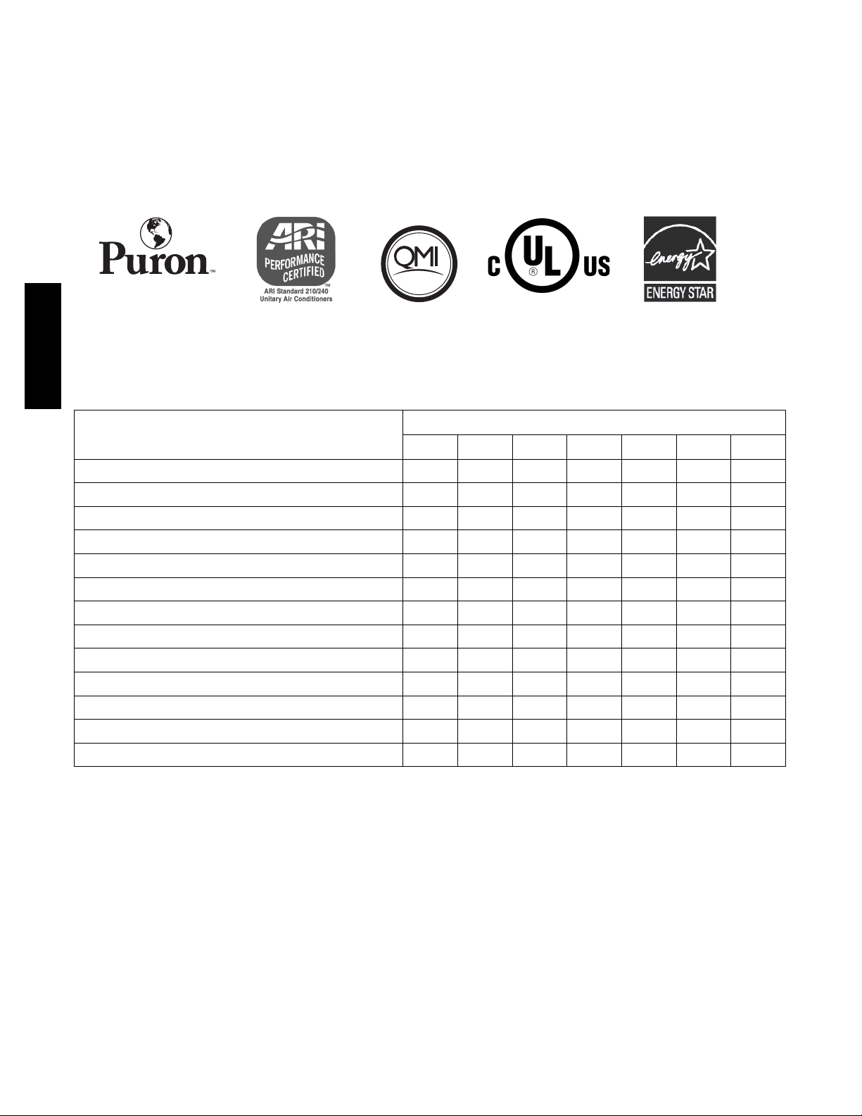
STANDARD FEATURES
FEATURES
018--- C 024--- D 030 ---D 036 ---C 042 ---D 048--- C 060--- C
Puron Refrigerant X X X X X X X
Maximum SEER Rating 15.5 16.0 16.0 16.0 16.0 15.0 14.5
Scroll Compressor X X X X X X X
Louvered Coil Guard X X X X X X X
FieldInstalledFilterDrier X X X X X X X
Front Seating Service Valves X X X X X X X
Internal Pressure Relief Valve X X X X X X X
Internal Thermal Overload X X X X X X X
Long Line capability X X X X X X X
Low Ambient capability with Kit X X X X X X X
Low Pressure (loss of charge) Switch X X X X X X X
High Pressure Switch X X X X X X X
Compressor Sound Blanket X X X X X X X
X=Standard
Unit Size --- Series
Series
A=
Original
Series
2
Page 3
PHYSICAL DATA
UNIT SIZE --- SERIES 018 --- C 024 --- D 030--- D 036---C 042---D 048 --- C 060 --- C
Operating Weight lb (kg) 195 (88.4) 184 (83.5) 177 (80.3) 225 (102.1) 228 (103.4) 270 (122.5) 337 (152.9)
Shipping Weight lb (kg) 223 (101.2) 223 (101.2) 218 (98.9) 259 (117.5) 267 (121.1) 303 (137.4) 372 (168.7)
Compressor Type Scroll
REFRIGERANT Puron® (R---410A)
Control TXV (Puron® Hard Shutoff)
Charge lb (kg) 5.4 (2.45) 5.48 (2.49) 5.8 (2.63) 6.97 (3.16) 9.5 (4.31) 11 (4.99) 13.3 (6.03)
COND FAN Propeller Type, Direct Drive
Air Discharge Vertical
Air Qty (CFM) 2235 3223 3223 3810 3810 3810 4050
Motor HP 1/12 1/12 1/12 1/5 1/5 1/5 1/4
Motor RPM 800 800 800 800 800 800 800
COND COIL
Face Area (Sq ft.) 19.40 17.60 17.60 22.63 17.60 20.12 30.18
Fins per In. 25 25 25 25 20 20 20
Rows 1 1 1 1 2 2 2
Circuits 3 4 4 5 7 7 7
VALVECONNECT.(In.ID)
Vapor 5/8 5/8 3/4 3/4 7/8 7/8 7/8
Liquid 3/8
REFRIGERANT TUBES (In. OD)
Rated Vapor* 5/8 3/4 7/8 1 --- 1 / 8
Liquid 3/8
*Units are rated with 25 ft (7.6 m) of lineset length. See Vapor Line Sizing and Cooling Capacity Loss table when using other sizes and lengths of lineset.
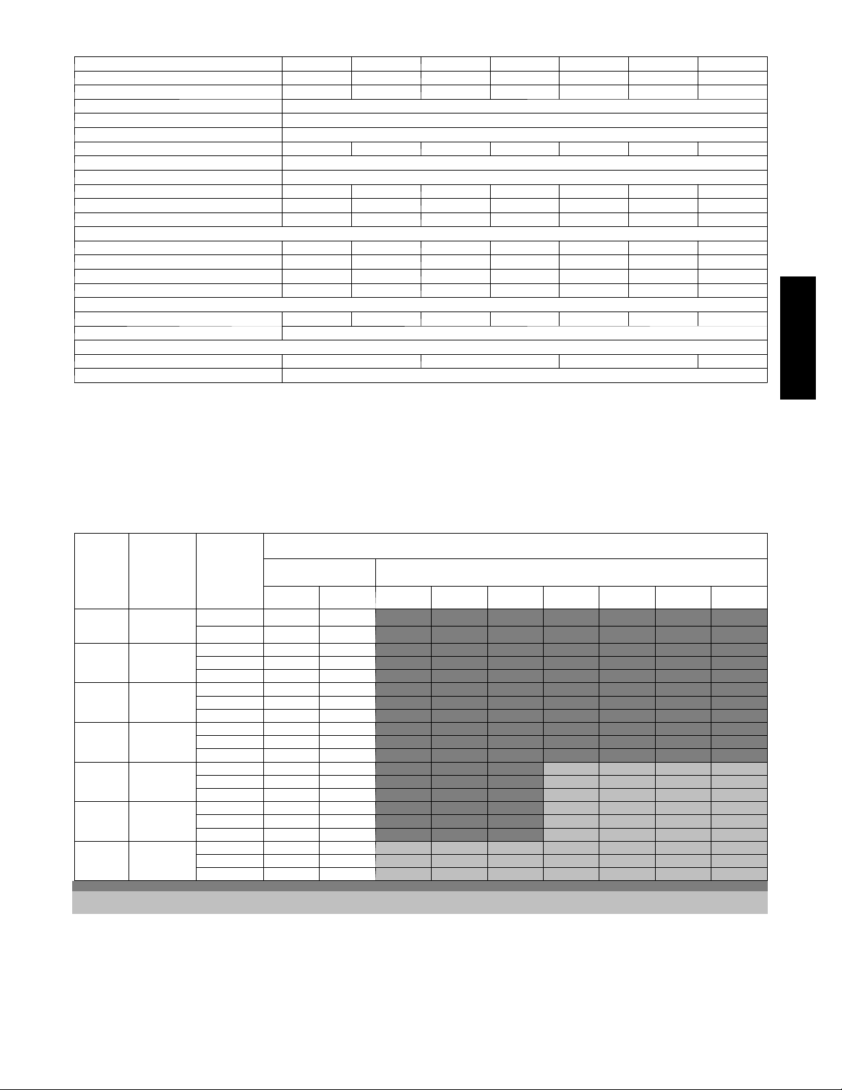
VAPOR LINE SIZING AND COOLING CAPACITY LOSS
LONG LINE APPLICATION: An application is considered
”Long line” when the total equivalent tubing length exceeds 80
ft. (24.38 m) or when there is more than 20 ft. (6.09 m) vertical
separation between indoor and outdoor units. These applications
require additional accessories and system modifications for
reliable system operation. The maximum allowable total
equivalent length is up to 250 ft. (76.2 m). The maximum
Unit
Nominal
Size
(Btuh)
18000
1Stage
Puron AC
24000
1Stage
Puron AC
30000
1Stage
Puron AC
36000
1Stage
Puron AC
42000
1Stage
Puron AC
48000
1Stage
Puron AC
60000
1Stage
Puron AC
Applications in this area are long line. Accessories are required as shown recommended on Long Line Application Guidelines
Applications in this area may have height restrictions that limit allowable total equivalent length, when outdoor unit is below indoor unit See Long Line Application Guidelines
Maximum
Liquid Line
Diameters
(In. OD)
3/8
3/8
3/8
3/8
3/8
3/8
3/8
Vapo r Line
Diameters
(In. OD)
1/2 1 2 3 4 6 7 8 9 10
5/8 0 0 1 1 1 2 2 3 3
5/8 0 1 1 2 3 3 4 4 5
3/4 0 0 0 0 1 1 1 1 1
7/8 0 0 0 0 0 0 0 0 0
5/8 1 2 3 3 4 5 6 7 8
3/4 0 0 1 1 1 2 2 2 3
7/8 0 0 0 0 1 1 1 1 1
5/8 1 2 4 5 6 7 9 10 11
3/4 0 0 1 1 2 2 3 3 4
7/8 0 0 0 0 1 1 1 1 2
3/4 0 1 2 2 3 4 4 5 6
7/8 0 0 1 1 1 2 2 2 3
11/8 0 0 0 0 0 0 0 0 0
3/4 0 1 2 3 4 5 5 6 7
7/8 0 0 1 1 2 2 2 3 3
11/8 0 0 0 0 0 0 0 1 1
3/4 1 2 4 5 6 7 9 10 11
7/8 0 1 2 2 3 4 4 5 5
11/8 0 0 0 1 1 1 1 1 1
Standard
Application
26---50
(7.9---15.2)
51---80
(15.5---24.4)
81---100
(24.7---30.5)
vertical separation is 200 ft. (60.96 m) when outdoor unit is
above indoor unit, and up to 80 ft. (24.38 m) when the outdoor
unit is below the indoor unit. Refer to Accessory Usage Guideline
below for required accessories. See Longline Application
Guideline for required piping and system modifications. Also,
refer to the table below for the vapor tube diameters based on the
total length to minimize the cooling capacity loss.
Cooling Capacity Loss (%)
Total Equivalent Line Length ft. (m)
Long Line Application Requires Accessories
101---125
(30.8---38.1)
126---150
(38.4---45.7)
151---175
(46.0---53.3)
176---200
(53.6---61.0)
201---225
(61.3---68.6)
226---250
(68.9---76.2)
124A
3
Page 4
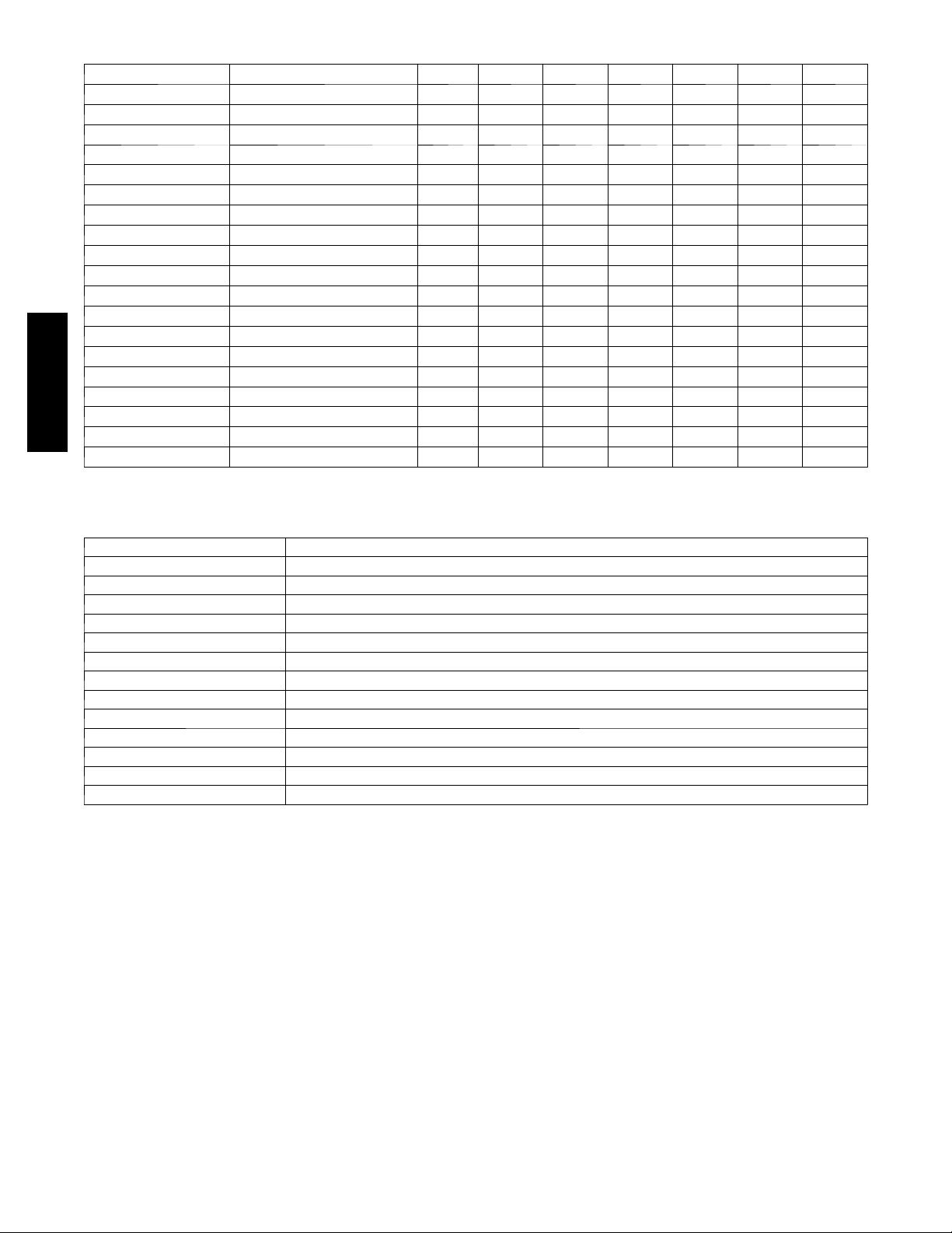
ACCESSORIES
ORDER NUMBER DESCRIPTION 018 --- C 024--- D 030--- D 036---C 042---D 048 --- C 060 ---C
KAACH1201AAA CRANKCASE HTR X X X
KAACH1401AAA CRANKCASE HTR X X X X
KSACY0101AAA CYCLE PROTECTOR X X X X X X X
KAAFT0101AAA FREEZE THERMOSTAT X X X X X X X
KSAHS1701AAA HARD START (CAP / RELAY) X X X X X X X
KSALA0301410* LOW AMBIENT PSW X X X X X X X
HC32GE229 MOTOR FAN BALL BEARING X X X
HC38GE228 MOTOR FAN BALL BEARING X X X
HC40GE228 MOTOR FAN BALL BEARING X
KSALA0601AAA* MOTORMASTER 230V X X X X X X X
KAALS0201LLS SOLENOID VALVE X X X X X X X
KAACS0201PTC STARTASSISTPTC X X X X X X X
KSASF0101AAA SUPPORT FEET X X X X X X X
KAATD0101TDR TIME DELAY RELAY X X X X X X X
KSATX0201PUR TXV P URON HSO X X X
KSATX0301PUR TXV P URON HSO X X
124A
KSATX0401PUR TXV P URON HSO X
KSATX0501PUR TXV P URON HSO X
KAAWS0101AAA WINTER START X X X X X X X
x = Accessory
* See Accessory Usage Guideline for other accessories n eeded for low ambient cooling applications.
THERMOSTATS
THERMOSTAT / SUBBASE PKG. DESCRIPTION
T 6 --- P R H --- 0 1 Programmable Thermidistat
T 6 --- N R H --- 0 1 Non--- programmable Thermidistat
T 2 --- P A C --- 0 1 Legacy Series Programmable AC Stat
T 2 --- N A C --- 0 1 Legacy Series Non--- programmable AC Stat
TSTATBBPRH01--- B Thermidistat Control --- Programmable / Non--- Programmable Thermostat with Humidity control
TSTATBBPAC01 --- B T h e r m o s t a t --- A u t o C h a n g e o v e r, 7 --- D a y P r o g r a m m a b l e , _F/_C , 1 --- S t a g e H e a t , 1 --- S t a g e C o o l
TSTATBBNAC01---C T h e r m o s t a t --- A u t o C h a n g e o v e r , N o n --- P r o g r a m m a b l e , _F/_C , 1 --- S t a g e H e a t , 1 --- S t a g e C o o l
TSTATBBBAC01 --- B Builder’s Thermostat --- Manual Changeover, Non ---Programmable, _F/_C , 1 --- S t a g e He a t , 1 --- S t a g e C o o l
TSTATBBSEN01--- B Outdoor Air Temperature Sensor
TSTATXXBBP01 Backplate f or Builder’s Thermostat
TSTATXXNBP01 Backplate for Non ---Programmable Thermostat
TSTATXXPBP01 Backplate for Programmable Thermostat
TSTATXXCNV10 Thermostat Conversion Kit (4 to 5 wires) --- 10 Pack
4
Page 5
ACCESSORY USAGE GUIDELI NE
REQUIRED FOR LOW--- AMBI-
ACCESSORY
Ball Bearing Fan Motor Yes { No No
Compressor Start Assist Capacitor and Relay Yes Yes No
Crankcase Heater Yes Yes No
Evaporator Freeze Thermostat Yes No No
H a r d S h u t --- O f f T X V Yes Yes Yes
Liquid Line Solenoid Valve No No No
Motor Master®Control or
L o w --- a m b i e n t P r e s s u r e S w i t c h
Support Feet Recommended No Recommended
* For tubing line sets between 80 and 200 ft. (24.38 and 60.96 m) a nd/or 20 ft. (6.09 m) vertical differential, ref er to Residential Split --- System Longline
Application Guideline.
{ Required for Low---Ambient Controller (full modulation feature) MotorMasterr Control.
Winter Start Control Yes No No
ENT COOLING APPLICATIONS
(Below 55°F/12.8_C)
Yes No No
REQUIRED FOR LONG
LINE
APPLICATIONS*
(Over 80 ft./24.38 m)
Accessory Description and Usage (Listed Alphabetically)
1. Ball--Bearing Fan Motor
A fan motor with ball bearings which permits speed reduction
while maintaining bearing lubrication.
Usage Guideline:
Required on all units when MotorMasterr —
2. Compressor Start Assist -- Capacitor and Relay
Start capacitor and relay gives a ”hard” boost to compressor
motor at each start up.
Usage Guideline:
Required for reciprocating compressors in the
following applications:
Long line
Low ambient cooling
Hard shut off expansion valve on indoor coil
Liquid line solenoid on indoor coil
Required for single--phase scroll compressors in the
following applications:
Long line
Low ambient cooling
Suggested for all compressors in areas with a history of
low voltage problems.
3. Compressor Start Assist — PTC Type
Solid state electrical device which gives a ”soft” boost to the
compressor at each start--up.
Usage Guideline:
Suggested in installations with marginal power supply.
4. Crankcase Heater
An electric resistance heater which mounts to the base of the
compressor to keep the lubricant warm during off cycles.
Improves compressor lubrication on restart and minimizes the
chance of liquid slugging.
Usage Guideline:
Required in low ambient cooling applications.
Required in long line applications.
Suggested in all commercial applications.
5. Cycle Protector
The cycle protector is designed to prevent compressor short
cycling. This control provides an approximate 5--minute delay
after power to the compressor has been interrupted for any
reason, including power outage, protector control trip, thermostat
jiggling, or normal cycling.
6. Evaporator Freeze Thermostat
An SPST temperature--actuated switch that stops unit operation
when evaporator reaches freeze--up conditions.
Usage Guideline:
Required when low ambient kit has been added.
7. Low--Ambient Pressure Switch Kit
A long life pressure switch which is mounted to outdoor unit
service valve. It is designed to cycle the outdoor fan motor in
order to maintain head pressure within normal operating limits
(approximately 100 psig/689.5 KpA to 225 psig/1551.3 KpA.
The control will maintain working head pressure at low--ambient
temperatures down to 0_F (--17.8_C) when properly installed.
Usage Guideline:
A Low --Ambient Pressure Switch or MotorMasterr
Low-- Ambient Controller must be used when cooling operation is
used at outdoor temperatures below 55_F (12.8_C).
8. MotorMasterr Low--Ambient Controller
A fan--speed control device activated by a temperature sensor,
designed to control condenser fan motor speed in response to the
saturated, condensing temperature during operation in cooling
mode only. For outdoor temperatures down to --20_F (--28.9_C),
it maintains condensing temperature at 100_F ±10_F (37.8_C ±
6.5_C).
Usage Guideline:
A MotorMasterr Low Ambient Controller or
Low-- Ambient Pressure Switch must be used when
cooling operation is used at outdoor temperatures
below 55_F (12.8_C).
Suggested for all commercial applications.
9. Outdoor Air Temperature Sensor
Designed for use with Bryant Thermostats listed in this
publ
i
cation. This device enables the thermostat to display the
outdoor temperature. This device also
is required to enable special thermostat features such as auxiliary
heat lock out.
Usage Guideline:
Suggested for all Bryant thermostats listed in this
publication.
REQUIRED FOR
SEA COAST
APPLICATIONS
(Within2miles/3.22km)
124A
5
Page 6

Accessory Description and Usage (Listed Alphabetically) (Continued)
10. Sound Hood
Wraparound sound reducing cover for the compressor. Reduces
the sound level by about 2 dBA.
Usage Guideline:
Suggested when unit is installed closer than 15 ft (4.57 m) to
quiet areas, bedrooms, etc.
Suggested when unit is installed between two houses less
than 10 ft (3.05 m) apart.
11. Support Feet
Four stick--on plastic feet that raise the unit 4 in. (101.6 mm)
above the mounting pad. This allows sand, dirt, and other debris
to be flushed from the unit base, minimizing corrosion.
Usage Guideline:
Suggested in the following applications:
Coastal installations.
Windy areas or where debris is normally circulating.
Rooftop installations.
For improved sound ratings.
124A
12. Thermostatic Expansion Valve (TXV)
A modulating flow--control valve which meters refrigerant liquid
flow rate into the evaporator in response to the superheat of the
refrigerant gas leaving the evaporator.
Kit includes valve, adapter tubes, and external equalizer tube.
Hard shut off types are available.
NOTE: When using a hard shut off TXV with single phase
reciprocating compressors, a Compressor Start Assist Capacitor
and Relay is required.
Usage Guideline:
Required to achieve ARI ratings in certain equipment
combinations. Refer to combination ratings.
Hard shut off TXV or LLS required in air conditioner
long line applications.
Required for use on all zoning systems.
13. Time--Delay Relay
An SPST delay relay which briefly continues operation of indoor
blower motor to provide additional cooling after the compressor
cycles off.
NOTE: Most indoor unit controls include this feature. For those
that do not, use the guideline below.
14. Winter Start Control
This control is designed to alleviate nuisance opening of the
low--pressure switch by bypassing it for the first 3 minutes of
operation.
Usage Guideline:
For improved efficiency ratings for certain
combinations of indoor and outdoor units. Refer to
ARI Unitary Directory.
6
Page 7
ELECTRICAL DATA
UNIT
S I Z E ---
SERIES
018 --- C
024 --- D 58.3 13.5 0.5 17.3 14 14 46 (14.0) 43 (13.1) 30
030 --- D 73.0 14.1 0.5 18.1 14 14 44 (13.4) 41 (12.5) 30
036 --- C 79.0 16.7 1.2 22.0 12 12 57 (17.4) 54 (16.5) 35
042 --- D 112.0 17.9 1.2 23.6 12 10 53 (16.2) 50 (15.2) 40
048 --- C 117.0 21.8 1.2 28.4 10 10 70 (21.3) 67 (20.4) 40
060 --- C 134.0 26.4 1.2 34.2 8 8 91 (27.7) 86 (26.2) 50
* Permissible limits of the voltage range at which th e unit will operate satisfactorily
{ If wire is applied at ambient greater th a n 30° C, consult table 310 --- 16 of the NEC (ANSI/NFPA 70). The ampacity of non --- metallic---sheathed cable (NM),
trade name ROMEX, shall be that of 60° C conditions, per the NEC (ANSI/NFPA 70) Article 336 ---26. If other than uncoated (no--- plated), 60 or 75° C
insulation, copper wire (solid wire for 10 AWG or smaller, stranded wire for larger than 10 AWG) is used, consult applicable tables of the NEC (ANSI/NFPA
70).
} Length shown is as measured 1 way along wire path between unit and service panel for voltage drop not to exceed 2%.
* * T ime --- D e l a y f u se.
FLA --- Fu l l L o a d Amp s
LRA --- L o c k ed R o t o r Am p s
MCA --- Minimum Circuit Amps
RLA ---RatedLoadAmps
NOTE: Control circuit is 24--- V on all units and requires external power source. Copper wire must be used from service disconnect to unit.
Complies with 2001 requirements of ASHRAE Standards 90.1
V/PH
208/230/1 253 197
All motors/compressors contain internal overload protection.
OPER
VOLTS*
MAX MIN LRA RLA FLA 60° C 75° C 60° C 75° C
COMPR FAN
48.0 9.0 0.5 11.7 14 14 67 (20.4) 64 (19.5) 15
MCA
MIN
WIRE
SIZE{
MIN WIRE
SIZE{
MAX
LENGTH
ft. (m)}
MAX
LENGTH
ft. (m)}
FUSE**
or CKT
AMPS
A--WEIGHTED SOUND POWER
U N I T S I Z E ---
VOLTAGE,
SERIES
018---C 73 56.0 60.0 65.0 69.0 63.0 60.0 52.5
024---D 74 51.0 60.0 66.5 66.5 64.0 60.0 52.5
030---D 74 53.0 62.0 68.5 69.0 65.5 61.0 54.0
036---C 72 52.0 62.0 65.5 67.5 63.0 61.0 53.5
042---D 74 60.0 65.5 68.5 68.5 65.0 60.0 52.5
048---C 73 59.5 63.5 66.5 67.5 64.0 62.0 55.5
060---C 74 55.5 64.0 67.0 69.0 65.0 60.0 54.5
NOTE: Tested in accordance with ARI Standard 270 --- 95. (Not listed with ARI).
STANDARD
RATING
(dBA)
TYPICAL OCTAVE BAND SPECTRUM (dBA, without tone adjustment)‘
125 250 500 1000 2000 4000 8000
MAX
BRK
124A
CHARGING SUBCOOLING (TXV--TYPE EXPANSION DEVICE)
UNIT SIZE ---VOLTAGE, SERIES REQUIRED SUBCOOLING _F(_C)
018 --- C 10 (5.6)
024 --- D 10 (5.6)
030 --- D 11 (6.1)
036 --- C 10 (5.6)
042 --- D 12 (6.7)
048 --- C 9 (5.0)
060 --- C 9 (5.0)
7
Page 8
124A
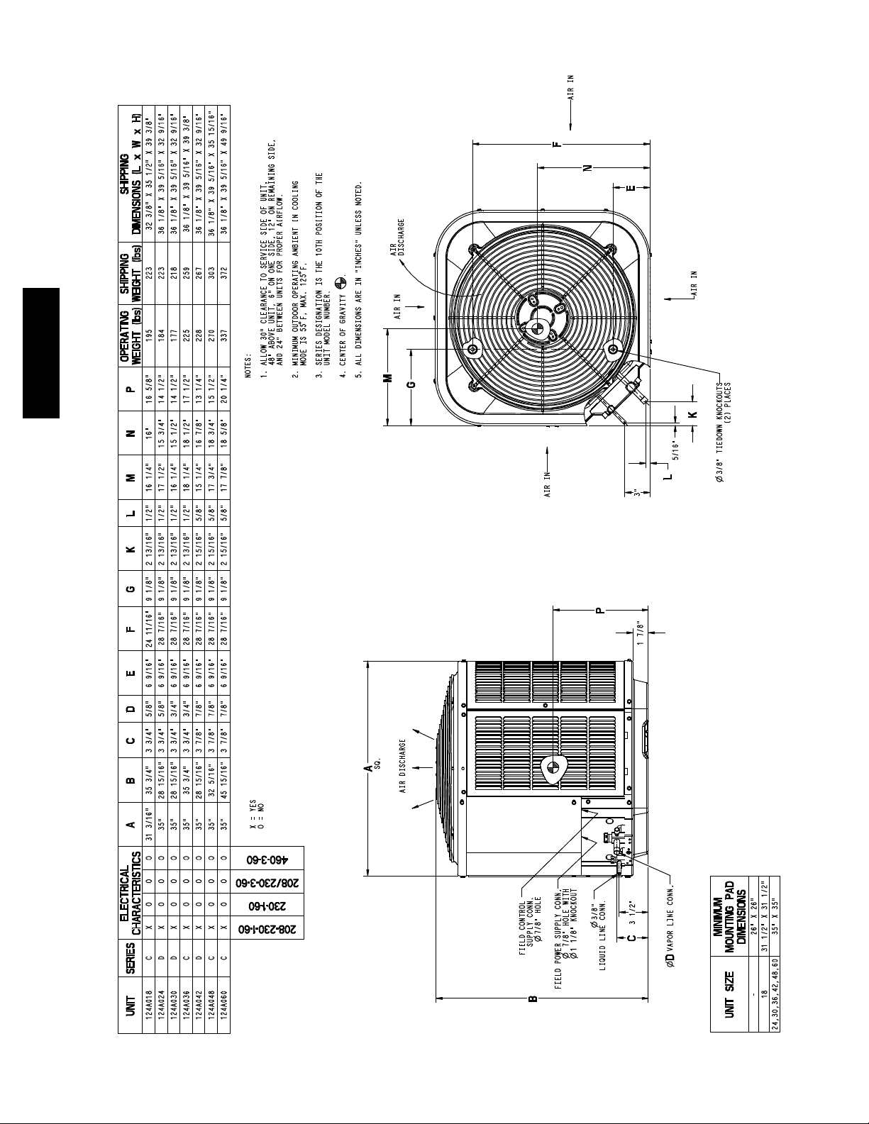
DIMENSIONS -- ENGLISH
8
Page 9
124A
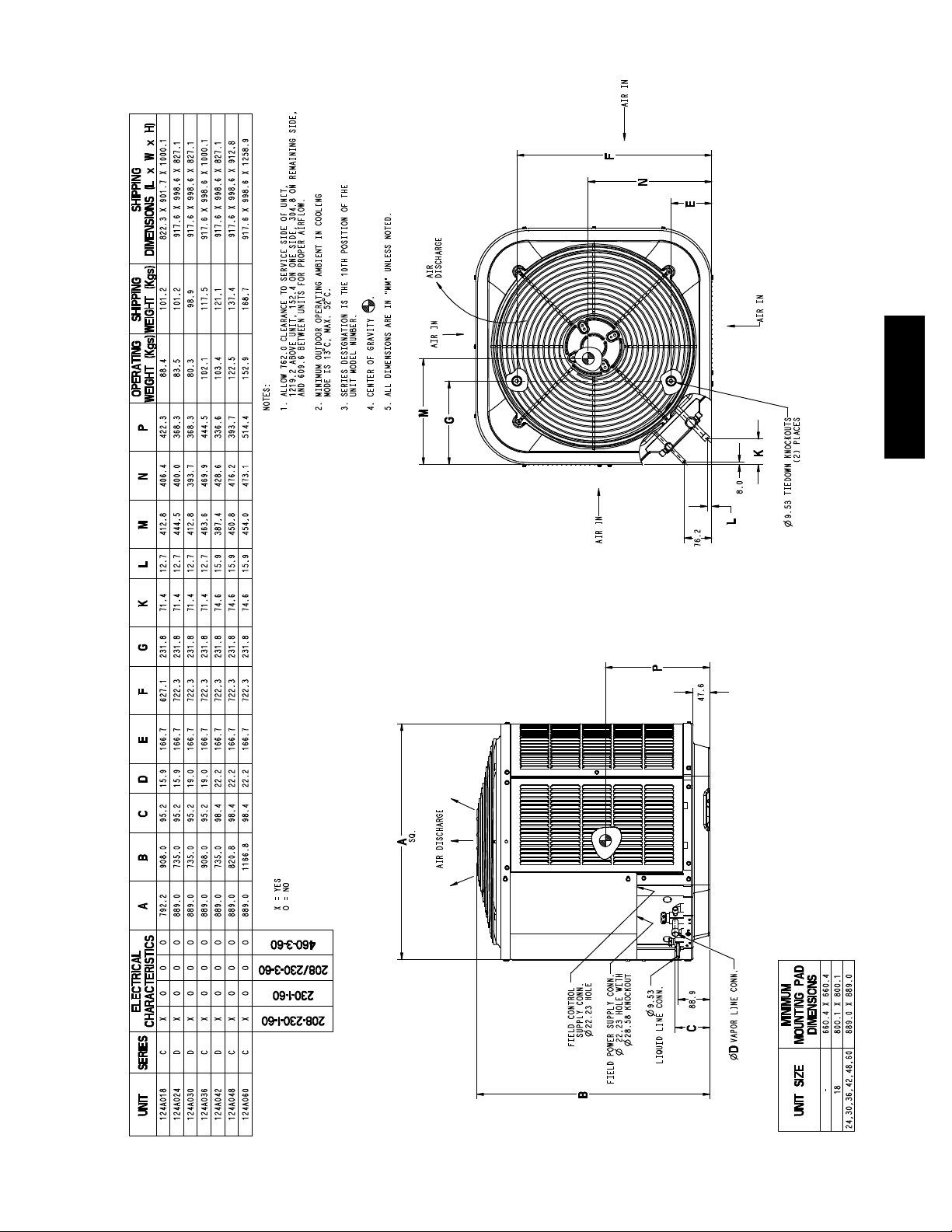
DIMENSIONS -- SI
9
Page 10
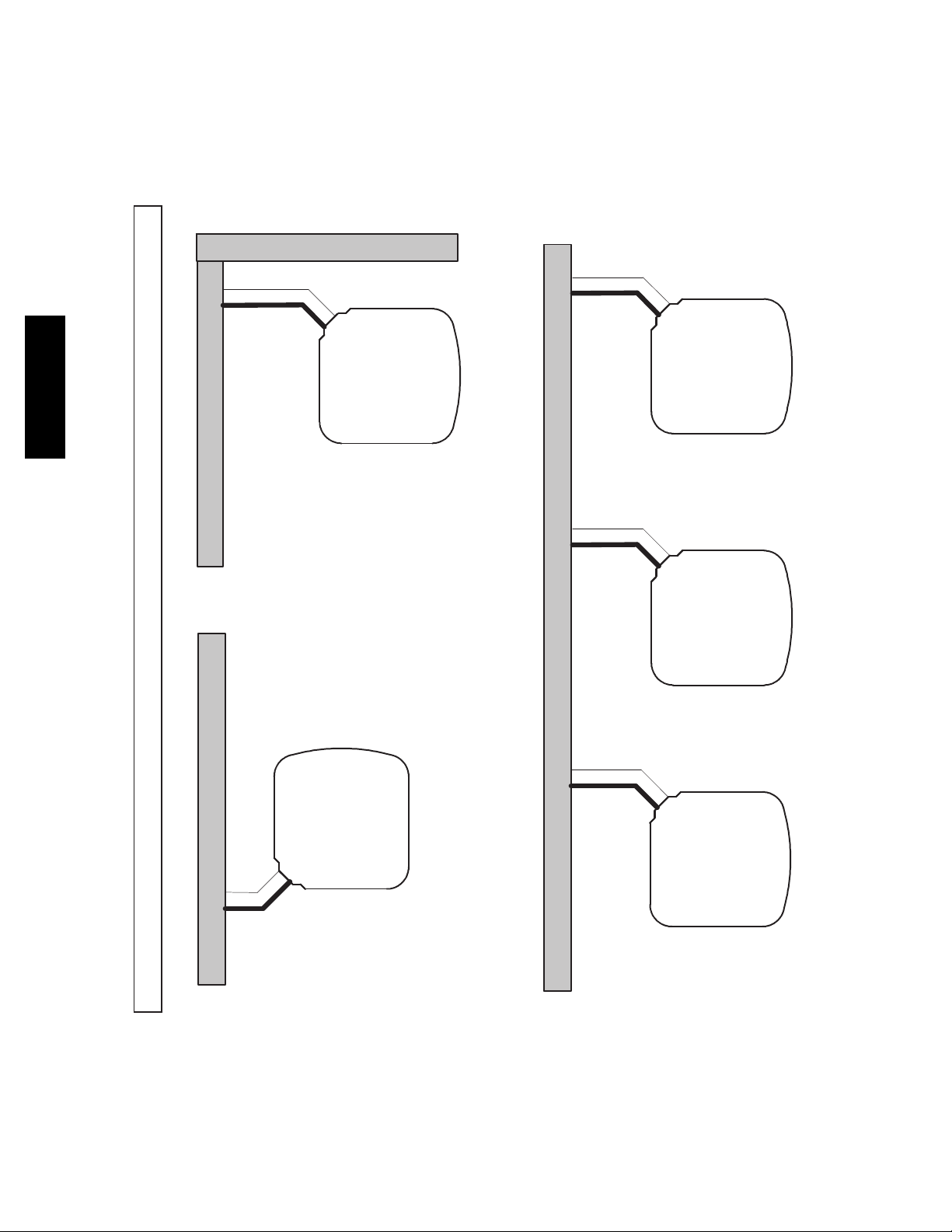
Wall
6”
A07833
(152.4)
124A
24”
Wall
Clearances (various examples)
Service
12”
(304.8)
6”
Wall
(152.4 mm)
12”
(304.8)
12”
(304.8)
12”
(304.8)
Wall
24”
(609.6)
24”
(609.6)
24”
(609.6)
Service
24”
(609.6)
Service
24”
(609.6)
Service
CLEARANCES
24”
(609.6)
Service
10
24”
(609.6)
Note: Numbers in ( ) = mm
Page 11

COMBINATION RATINGS
ARI Ref. No. Model Number Indoor Model Furnace Model Capacity EER SEER Phase
3047865 124ANA018--- C *CAP**2414A**+TDR 18000 11.50 14.00 1
3047866 124ANA018--- C CAP**1814A** 313*AV024045 18000 12.75 15.25 1
3047873 124ANA018--- C CAP**1814A** 315(A,J)AV036070 17600 12.50 15.00 1
3047872 124ANA018--- C CAP**1814A**+TDR 17800 11.20 13.50 1
3047867 124ANA018--- C CAP**2414A** 313*AV024045 18200 13.00 15.50 1
3047874 124ANA018--- C CAP**2414A** 315(A,J)AV036070 17900 13.00 15.50 1
3047877 124ANA018--- C CAP**2417A** 315(A,J)AV048090 17900 13.00 15.50 1
3101972 124ANA018--- C CAP**2417A** 353AAV036040 18000 13.20 16.00 1
3101973 124ANA018--- C CAP**2417A** 353AAV036060 18000 13.20 16.00 1
3047876 124ANA018--- C CAP**2417A** 355(A,C)AV042060 17900 13.00 15.50 1
3047875 124ANA018--- C CAP**2417A**+TDR 18000 11.50 14.00 1
3047891 124ANA018--- C CNPF*2418A**+TDR 18000 11.50 14.00 1
3047870 124ANA018--- C CNPH*2417A** 313*AV024045 18200 13.00 15.50 1
3047889 124ANA018--- C CNPH*2417A** 315(A,J)AV036070 17900 13.00 15.50 1
3047890 124ANA018--- C CNPH*2417A** 315(A,J)AV048090 17900 13.00 15.50 1
3101976 124ANA018--- C CNPH*2417A** 353AAV036040 18000 13.00 15.75 1
3101977 124ANA018--- C CNPH*2417A** 353AAV036060 18000 13.00 15.75 1
3047886 124ANA018--- C CNPH*2417A** 355(A,C)AV042040 17900 13.00 15.50 1
3047887 124ANA018--- C CNPH*2417A** 355(A,C)AV042060 17900 13.00 15.50 1
3047888 124ANA018--- C CNPH*2417A** 355(A,C)AV042080 17900 13.00 15.50 1
3047885 124ANA018--- C CNPH*2417A**+TDR 18000 11.50 14.00 1
3047868 124ANA018--- C CNPV*1814A** 313*AV024045 18000 12.75 15.25 1
3047879 124ANA018--- C CNPV*1814A** 315(A ,J)AV036070 17600 12.50 15.00 1
3047878 124ANA018--- C CNPV*1814A**+TDR 17800 11.20 13.50 1
3047869 124ANA018--- C CNPV*2414A** 313*AV024045 18200 13.00 15.50 1
3047881 124ANA018--- C CNPV*2414A** 315(A ,J)AV036070 17900 13.00 15.50 1
3047880 124ANA018--- C CNPV*2414A**+TDR 18000 11.50 14.00 1
3047884 124ANA018--- C CNPV*2417A** 315(A ,J)AV048090 17900 13.00 15.50 1
3101974 124ANA018--- C CNPV*2417A** 353AAV036040 18000 13.00 15.75 1
3101975 124ANA018--- C CNPV*2417A** 353AAV036060 18000 13.00 15.75 1
3047883 124ANA018--- C CNPV*2417A** 355(A,C)AV042060 17900 13.00 15.50 1
3047882 124ANA018--- C CNPV*2417A**+TDR 18000 11.50 14.00 1
3047871 124ANA018--- C CSPH*2412A** 313*AV024045 18200 13.00 15.50 1
3047896 124ANA018--- C CSPH*2412A** 315(A,J)AV036070 17900 13.00 15.50 1
3047897 124ANA018--- C CSPH*2412A** 315(A,J)AV048090 17900 13.00 15.50 1
3101978 124ANA018--- C CSPH*2412A** 353AAV036040 18000 13.00 15.75 1
3101979 124ANA018--- C CSPH*2412A** 353AAV036060 18000 13.00 15.75 1
3047893 124ANA018--- C CSPH*2412A** 355(A,C)AV042040 17900 13.00 15.50 1
3047894 124ANA018--- C CSPH*2412A** 355(A,C)AV042060 17900 13.00 15.50 1
3047895 124ANA018--- C CSPH*2412A** 355(A,C)AV042080 17900 13.00 15.50 1
3047892 124ANA018--- C CSPH*2412A**+TDR 18000 12.00 14.00 1
3047902 124ANA018--- C FE4ANF002+UI 18200 13.20 16.00 1
3047903 124ANA018--- C FF1ENP018 17800 11.20 13.50 1
3047904 124ANA018--- C FF1ENP024 18000 11.20 13.50 1
3047905 124ANA018--- C FV4BNF002 18200 13.20 16.00 1
3047900 124ANA018--- C FX4CNF018 18000 13.00 15.50 1
3047901 124ANA018--- C FX4CNF024 18300 13.00 15.50 1
3047898 124ANA018--- C FY4ANF018 17800 11.20 13.50 1
3047899 124ANA018--- C FY4ANF024 17900 11.20 13.50 1
3047906 124ANA024--- D *CAP**2414A**+TDR 23200 11.70 14.00 1
3047907 124ANA024--- D CAP**2414A** 313*AV024045 23200 12.75 15.25 1
3047915 124ANA024--- D CAP**2414A** 315(A,J)AV036070 23000 13.00 15.50 1
3047918 124ANA024--- D CAP**2417A** 315(A,J)AV048090 23000 13.00 15.50 1
3101980 124ANA024--- D CAP**2417A** 353AAV036040 23200 13.00 15.75 1
3101981 124ANA024--- D CAP**2417A** 353AAV036060 23200 13.00 15.75 1
3101982 124ANA024--- D CAP**2417A** 353AAV036080 23200 13.00 15.75 1
3047917 124ANA024--- D CAP**2417A** 355(A,C)AV042060 23000 13.00 15.50 1
3047916 124ANA024--- D CAP**2417A**+TDR 23200 11.70 14.00 1
3047908 124ANA024--- D CAP**3014A** 313*AV024045 23400 13.00 15.50 1
3047920 124ANA024--- D CAP**3014A** 315(A,J)AV036070 23200 13.00 15.50 1
3047919 124ANA024--- D CAP**3014A**+TDR 23400 12.00 14.00 1
3047923 124ANA024--- D CAP**3017A** 315(A,J)AV048090 23200 13.20 16.00 1
3101983 124ANA024--- D CAP**3017A** 353AAV036040 23800 13.20 16.00 1
3101984 124ANA024--- D CAP**3017A** 353AAV036060 23800 13.20 16.00 1
3101985 124ANA024--- D CAP**3017A** 353AAV036080 23800 13.20 16.00 1
3047922 124ANA024--- D CAP**3017A** 355(A,C)AV042060 23200 13.00 15.50 1
3047921 124ANA024--- D CAP**3017A**+TDR 23400 12.00 14.00 1
3047958 124ANA024--- D CNPF*2418A**+TDR 23200 11.70 14.00 1
3047911 124ANA024--- D CNPH*2417A** 313*AV024045 23000 12.75 15.25 1
3047941 124ANA024--- D CNPH*2417A** 315(A,J)AV036070 22800 12.50 15.50 1
3047942 124ANA024--- D CNPH*2417A** 315(A,J)AV048090 23000 13.00 15.50 1
3047943 124ANA024--- D CNPH*2417A** 315(A,J)AV060110 23000 12.50 15.50 1
3047944 124ANA024--- D CNPH*2417A** 315(A,J)AV066135 23000 13.00 15.50 1
3047945 124ANA024--- D CNPH*2417A** 315(A,J)AV066155 23000 13.00 15.50 1
3101992 124ANA024--- D CNPH*2417A** 353AAV036040 23200 13.00 15.75 1
3101993 124ANA024--- D CNPH*2417A** 353AAV036060 23200 13.00 15.75 1
3101994 124ANA024--- D CNPH*2417A** 353AAV036080 23200 13.00 15.75 1
3047935 124ANA024--- D CNPH*2417A** 355(A,C)AV042040 23000 12.50 15.50 1
3047936 124ANA024--- D CNPH*2417A** 355(A,C)AV042060 23000 13.00 15.50 1
3047937 124ANA024--- D CNPH*2417A** 355(A,C)AV042080 23000 12.50 15.50 1
3047938 124ANA024--- D CNPH*2417A** 355(A,C)AV060080 22800 13.00 15.50 1
3047939 124ANA024--- D CNPH*2417A** 355(A,C)AV060100 23000 13.00 15.50 1
3047940 124ANA024--- D CNPH*2417A** 355(A,C)AV060120 22800 12.50 15.00 1
3047934 124ANA024--- D CNPH*2417A**+TDR 23200 11.70 14.00 1
3047912 124ANA024--- D CNPH*3017A** 313*AV024045 23600 13.00 15.25 1
3047953 124ANA024--- D CNPH*3017A** 315(A,J)AV036070 23200 13.00 15.50 1
3047954 124ANA024--- D CNPH*3017A** 315(A,J)AV048090 23200 13.20 16.00 1
3047955 124ANA024--- D CNPH*3017A** 315(A,J)AV060110 23200 13.00 15.50 1
See notes on page 19
124A
11
Page 12

COMBINATION RATINGS CONTINUED
ARI Ref. No. Model Number Indoor Model Furnace Model Capacity EER SEER Phase
3047956 124ANA024--- D CNPH*3017A** 315(A,J)AV066135 23400 13.00 15.50 1
3047957 124ANA024--- D CNPH*3017A** 315(A,J)AV066155 23400 13.20 16.00 1
3101995 124ANA024--- D CNPH*3017A** 353AAV036040 23800 13.20 16.00 1
3101996 124ANA024--- D CNPH*3017A** 353AAV036060 23800 13.20 16.00 1
3101997 124ANA024--- D CNPH*3017A** 353AAV036080 23800 13.20 16.00 1
3047947 124ANA024--- D CNPH*3017A** 355(A,C)AV042040 23200 13.00 15.50 1
3047948 124ANA024--- D CNPH*3017A** 355(A,C)AV042060 23200 13.00 15.50 1
3047949 124ANA024--- D CNPH*3017A** 355(A,C)AV042080 23200 13.00 15.50 1
3047950 124ANA024--- D CNPH*3017A** 355(A,C)AV060080 23000 13.00 15.50 1
3047951 124ANA024--- D CNPH*3017A** 355(A,C)AV060100 23200 13.00 15.50 1
3047952 124ANA024--- D CNPH*3017A** 355(A,C)AV060120 23200 13.00 15.50 1
3047946 124ANA024--- D CNPH*3017A**+TDR 23400 12.00 14.00 1
3047909 124ANA024--- D CNPV*2414A** 313*AV024045 23000 12.75 15.25 1
3047925 124ANA024--- D CNPV*2414A** 315(A,J)AV036070 22800 12.50 15.50 1
3047924 124ANA024--- D CNPV*2414A**+TDR 23200 11.70 14.00 1
3047928 124ANA024--- D CNPV*2417A** 315(A,J)AV048090 23000 13.00 15.50 1
3101986 124ANA024--- D CNPV*2417A** 353AAV036040 23200 13.00 15.75 1
3101987 124ANA024--- D CNPV*2417A** 353AAV036060 23200 13.00 15.75 1
3101988 124ANA024--- D CNPV*2417A** 353AAV036080 23200 13.00 15.75 1
3047927 124ANA024--- D CNPV*2417A** 355(A,C)AV042060 23000 13.00 15.50 1
3047926 124ANA024--- D CNPV*2417A**+TDR 23200 11.70 14.00 1
3047910 124ANA024--- D CNPV*3014A** 313*AV024045 23400 13.00 15.50 1
3047930 124ANA024--- D CNPV*3014A** 315(A,J)AV036070 23200 13.00 15.50 1
3047929 124ANA024--- D CNPV*3014A**+TDR 23400 12.00 14.00 1
3047933 124ANA024--- D CNPV*3017A** 315(A,J)AV048090 23200 13.20 16.00 1
3101989 124ANA024--- D CNPV*3017A** 353AAV036040 23800 13.20 16.00 1
124A
3101990 124ANA024--- D CNPV*3017A** 353AAV036060 23800 13.20 16.00 1
3101991 124ANA024--- D CNPV*3017A** 353AAV036080 23800 13.20 16.00 1
3047932 124ANA024--- D CNPV*3017A** 355(A,C)AV042060 23200 13.00 15.50 1
3047931 124ANA024--- D CNPV*3017A**+TDR 23400 12.00 14.00 1
3047913 124ANA024--- D CSPH*2412A** 313*AV024045 23200 13.00 15.50 1
3047966 124ANA024--- D CSPH*2412A** 315(A,J)AV036070 23200 13.00 15.50 1
3047967 124ANA024--- D CSPH*2412A** 315(A,J)AV048090 23200 13.00 15.50 1
3047968 124ANA024--- D CSPH*2412A** 315(A,J)AV060110 23200 13.00 15.50 1
3047969 124ANA024--- D CSPH*2412A** 315(A,J)AV066135 23200 13.00 15.50 1
3047970 124ANA024--- D CSPH*2412A** 315(A,J)AV066155 23200 13.00 15.50 1
3101998 124ANA024--- D CSPH*2412A** 353AAV036040 23200 13.00 15.75 1
3101999 124ANA024--- D CSPH*2412A** 353AAV036060 23200 13.00 15.75 1
3102000 124ANA024--- D CSPH*2412A** 353AAV036080 23200 13.00 15.75 1
3047960 124ANA024--- D CSPH*2412A** 355(A,C)AV042040 23200 13.00 15.50 1
3047961 124ANA024--- D CSPH*2412A** 355(A,C)AV042060 23200 13.00 15.50 1
3047962 124ANA024--- D CSPH*2412A** 355(A,C)AV042080 23200 13.00 15.50 1
3047963 124ANA024--- D CSPH*2412A** 355(A,C)AV060080 23000 13.00 15.50 1
3047964 124ANA024--- D CSPH*2412A** 355(A,C)AV060100 23200 13.00 15.50 1
3047965 124ANA024--- D CSPH*2412A** 355(A,C)AV060120 23200 13.00 15.50 1
3047959 124ANA024--- D CSPH*2412A**+TDR 23400 12.00 14.00 1
3047914 124ANA024--- D CSPH*3012A** 313*AV024045 23600 13.00 15.50 1
3047978 124ANA024--- D CSPH*3012A** 315(A,J)AV036070 23200 13.00 15.50 1
3047979 124ANA024--- D CSPH*3012A** 315(A,J)AV048090 23400 13.20 16.00 1
3047980 124ANA024--- D CSPH*3012A** 315(A,J)AV060110 23400 13.00 15.50 1
3047981 124ANA024--- D CSPH*3012A** 315(A,J)AV066135 23400 13.00 15.50 1
3047982 124ANA024--- D CSPH*3012A** 315(A,J)AV066155 23400 13.00 15.50 1
3102001 124ANA024--- D CSPH*3012A** 353AAV036040 23800 13.20 16.00 1
3102002 124ANA024--- D CSPH*3012A** 353AAV036060 23800 13.20 16.00 1
3102003 124ANA024--- D CSPH*3012A** 353AAV036080 23800 13.20 16.00 1
3047972 124ANA024--- D CSPH*3012A** 355(A,C)AV042040 23400 13.00 15.50 1
3047973 124ANA024--- D CSPH*3012A** 355(A,C)AV042060 23400 13.00 15.50 1
3047974 124ANA024--- D CSPH*3012A** 355(A,C)AV042080 23200 13.00 15.50 1
3047975 124ANA024--- D CSPH*3012A** 355(A,C)AV060080 23000 13.00 15.50 1
3047976 124ANA024--- D CSPH*3012A** 355(A,C)AV060100 23400 13.00 15.50 1
3047977 124ANA024--- D CSPH*3012A** 355(A,C)AV060120 23200 13.00 15.50 1
3047971 124ANA024--- D CSPH*3012A**+TDR 23600 12.00 14.00 1
3047988 124ANA024--- D FE4AN(B,F)003+UI 23600 13.20 16.00 1
3047987 124ANA024--- D FE4ANF002+UI 23400 13.20 16.00 1
3047989 124ANA024--- D FE5ANB004+UI 24200 13.20 16.00 1
3047992 124ANA024--- D FF1ENP024 23000 11.70 13.50 1
3047993 124ANA024--- D FF1ENP030 23000 11.70 13.50 1
3047991 124ANA024--- D FV4BN(B,F)003 23600 13.20 16.00 1
3047990 124ANA024--- D FV4BNF002 23400 13.20 16.00 1
3047985 124ANA024--- D FX4CNF024 23400 12.50 15.00 1
3047986 124ANA024--- D FX4CNF030 23600 13.00 15.50 1
3047983 124ANA024--- D FY4ANF024 23000 11.70 14.00 1
3047984 124ANA024--- D FY4ANF030 23200 12.00 14.00 1
3047994 124ANA030--- D *CAP**3014A**+TDR 29000 11.70 14.00 1
3048009 124ANA030--- D CAP**3014A** 315(A,J)AV036070 28800 12.50 15.00 1
3047995 124ANA030--- D CAP**3017A** 313*AV048070 29000 12.50 15.00 1
3048012 124ANA030--- D CAP**3017A** 315(A,J)AV048090 28800 12.50 15.50 1
3102020 124ANA030--- D CAP**3017A** 353AAV036040 29200 13.00 15.50 1
3102021 124ANA030--- D CAP**3017A** 353AAV036060 29200 13.00 15.50 1
3102022 124ANA030--- D CAP**3017A** 353AAV036080 29200 13.00 15.50 1
3102023 124ANA030--- D CAP**3017A** 353AAV048080 29200 12.50 15.00 1
3048011 124ANA030--- D CAP**3017A** 355(A,C)AV042060 28800 12.50 15.00 1
3048010 124ANA030--- D CAP**3017A**+TDR 29000 11.70 14.00 1
3048014 124ANA030--- D CAP**3614A** 315(A,J)AV036070 28800 12.50 15.00 1
3048013 124ANA030--- D CAP**3614A**+TDR 28200 11.70 14.00 1
3047996 124ANA030--- D CAP**3617A** 313*AV048070 29200 12.50 15.00 1
3048017 124ANA030--- D CAP**3617A** 315(A,J)AV048090 29000 13.00 15.50 1
3102024 124ANA030--- D CAP**3617A** 353AAV036040 29200 13.00 15.50 1
See notes on page 19
12
Page 13

COMBINATION RATINGS CONTINUED
ARI Ref. No. Model Number Indoor Model Furnace Model Capacity EER SEER Phase
3102025 124ANA030--- D CAP**3617A** 353AAV036060 29200 13.00 15.50 1
3102026 124ANA030--- D CAP**3617A** 353AAV036080 29200 13.00 15.50 1
3102027 124ANA030--- D CAP**3617A** 353AAV048080 29200 13.00 15.50 1
3048016 124ANA030--- D CAP**3617A** 355(A,C)AV042060 28800 12.50 15.00 1
3048015 124ANA030--- D CAP**3617A**+TDR 29200 11.70 14.00 1
3047997 124ANA030--- D CAP**3621A** 313*AV048090 29400 13.00 15.50 1
3048022 124ANA030--- D CAP**3621A** 315(A,J)AV060110 29000 13.00 15.50 1
3048019 124ANA030--- D CAP**3621A** 355(A,C)AV042080 28800 12.50 15.50 1
3048020 124ANA030--- D CAP**3621A** 355(A,C)AV060080 29000 12.50 15.50 1
3048021 124ANA030--- D CAP**3621A** 355(A,C)AV060100 28800 12.50 15.50 1
3048018 124ANA030--- D CAP**3621A**+TDR 29200 11.70 14.00 1
3048060 124ANA030--- D CNPF*3618A**+TDR 29000 11.70 14.00 1
3048001 124ANA030--- D CNPH*3017A** 313*AV048070 29000 12.50 15.00 1
3048002 124ANA030--- D CNPH*3017A** 313*AV048090 29000 12.50 15.25 1
3048043 124ANA030--- D CNPH*3017A** 315(A,J)AV036070 28800 12.50 15.00 1
3048044 124ANA030--- D CNPH*3017A** 315(A,J)AV048090 28800 12.50 15.50 1
3048045 124ANA030--- D CNPH*3017A** 315(A,J)AV060110 29000 12.50 15.50 1
3048046 124ANA030--- D CNPH*3017A** 315(A,J)AV066135 29000 12.50 15.00 1
3048047 124ANA030--- D CNPH*3017A** 315(A,J)AV066155 29000 13.00 15.50 1
3102004 124ANA030--- D CNPH*3017A** 353AAV036040 29200 13.00 15.50 1
3102005 124ANA030--- D CNPH*3017A** 353AAV036060 29200 13.00 15.50 1
3102006 124ANA030--- D CNPH*3017A** 353AAV036080 29200 13.00 15.50 1
3102007 124ANA030--- D CNPH*3017A** 353AAV048080 29200 12.50 15.00 1
3048037 124ANA030--- D CNPH*3017A** 355(A,C)AV042040 28800 12.50 15.00 1
3048038 124ANA030--- D CNPH*3017A** 355(A,C)AV042060 28800 12.50 15.00 1
3048039 124ANA030--- D CNPH*3017A** 355(A,C)AV042080 28800 12.50 15.00 1
3048040 124ANA030--- D CNPH*3017A** 355(A,C)AV060080 28800 12.50 15.00 1
3048041 124ANA030--- D CNPH*3017A** 355(A,C)AV060100 28600 12.50 15.00 1
3048042 124ANA030--- D CNPH*3017A** 355(A,C)AV060120 28800 12.50 15.00 1
3048036 124ANA030--- D CNPH*3017A**+TDR 29000 11.70 14.00 1
3048003 124ANA030--- D CNPH*3617A** 313*AV048070 29000 12.50 15.00 1
3048004 124ANA030--- D CNPH*3617A** 313*AV048090 29000 12.50 15.25 1
3048055 124ANA030--- D CNPH*3617A** 315(A,J)AV036070 28800 12.50 15.00 1
3048056 124ANA030--- D CNPH*3617A** 315(A,J)AV048090 28800 12.50 15.50 1
3048057 124ANA030--- D CNPH*3617A** 315(A,J)AV060110 29000 12.50 15.50 1
3048058 124ANA030--- D CNPH*3617A** 315(A,J)AV066135 29000 12.50 15.50 1
3048059 124ANA030--- D CNPH*3617A** 315(A,J)AV066155 29000 13.00 15.50 1
3102008 124ANA030--- D CNPH*3617A** 353AAV036040 29200 13.00 15.50 1
3102009 124ANA030--- D CNPH*3617A** 353AAV036060 29200 13.00 15.50 1
3102010 124ANA030--- D CNPH*3617A** 353AAV036080 29200 13.00 15.50 1
3102011 124ANA030--- D CNPH*3617A** 353AAV048080 29200 12.50 15.00 1
3048049 124ANA030--- D CNPH*3617A** 355(A,C)AV042040 28800 12.50 15.00 1
3048050 124ANA030--- D CNPH*3617A** 355(A,C)AV042060 28800 12.50 15.00 1
3048051 124ANA030--- D CNPH*3617A** 355(A,C)AV042080 28800 12.50 15.00 1
3048052 124ANA030--- D CNPH*3617A** 355(A,C)AV060080 28800 12.50 15.00 1
3048053 124ANA030--- D CNPH*3617A** 355(A,C)AV060100 28600 12.50 15.00 1
3048054 124ANA030--- D CNPH*3617A** 355(A,C)AV060120 28800 12.50 15.00 1
3048048 124ANA030--- D CNPH*3617A**+TDR 29000 11.70 14.00 1
3048024 124ANA030--- D CNPV*3014A** 315(A,J)AV036070 28800 12.50 15.00 1
3048023 124ANA030--- D CNPV*3014A**+TDR 29000 11.70 14.00 1
3047998 124ANA030--- D CNPV*3017A** 313*AV048070 29000 12.50 15.00 1
3048027 124ANA030--- D CNPV*3017A** 315(A,J)AV048090 28800 12.50 15.50 1
3102028 124ANA030--- D CNPV*3017A** 353AAV036040 29200 13.00 15.50 1
3102029 124ANA030--- D CNPV*3017A** 353AAV036060 29200 13.00 15.50 1
3102030 124ANA030--- D CNPV*3017A** 353AAV036080 29200 13.00 15.50 1
3102031 124ANA030--- D CNPV*3017A** 353AAV048080 29200 12.50 15.00 1
3048026 124ANA030--- D CNPV*3017A** 355(A,C)AV042060 28800 12.50 15.00 1
3048025 124ANA030--- D CNPV*3017A**+TDR 29000 11.70 14.00 1
3047999 124ANA030--- D CNPV*3617A** 313*AV048070 29000 12.50 15.00 1
3048030 124ANA030--- D CNPV*3617A** 315(A,J)AV048090 28800 12.50 15.50 1
3102032 124ANA030--- D CNPV*3617A** 353AAV036040 29200 13.00 15.50 1
3102033 124ANA030--- D CNPV*3617A** 353AAV036060 29200 13.00 15.50 1
3102034 124ANA030--- D CNPV*3617A** 353AAV036080 29200 13.00 15.50 1
3102035 124ANA030--- D CNPV*3617A** 353AAV048080 29200 12.50 15.00 1
3048029 124ANA030--- D CNPV*3617A** 355(A,C)AV042060 28800 12.50 15.00 1
3048028 124ANA030--- D CNPV*3617A**+TDR 29000 11.70 14.00 1
3048000 124ANA030--- D CNPV*3621A** 313*AV048090 29000 12.50 15.25 1
3048035 124ANA030--- D CNPV*3621A** 315(A,J)AV060110 29000 12.50 15.50 1
3048032 124ANA030--- D CNPV*3621A** 355(A,C)AV042080 28800 12.50 15.00 1
3048033 124ANA030--- D CNPV*3621A** 355(A,C)AV060080 28800 12.50 15.00 1
3048034 124ANA030--- D CNPV*3621A** 355(A,C)AV060100 28600 12.50 15.00 1
3048031 124ANA030--- D CNPV*3621A**+TDR 29000 11.70 14.00 1
3048005 124ANA030--- D CSPH*3012A** 313*AV048070 29000 12.50 15.00 1
3048006 124ANA030--- D CSPH*3012A** 313*AV048090 29000 12.50 15.25 1
3048068 124ANA030--- D CSPH*3012A** 315(A,J)AV036070 29000 12.50 15.00 1
3048069 124ANA030--- D CSPH*3012A** 315(A,J)AV048090 29000 12.50 15.50 1
3048070 124ANA030--- D CSPH*3012A** 315(A,J)AV060110 29000 12.50 15.00 1
3048071 124ANA030--- D CSPH*3012A** 315(A,J)AV066135 29000 12.50 15.50 1
3048072 124ANA030--- D CSPH*3012A** 315(A,J)AV066155 29000 12.50 15.50 1
3102012 124ANA030--- D CSPH*3012A** 353AAV036040 29200 13.00 15.50 1
3102013 124ANA030--- D CSPH*3012A** 353AAV036060 29200 13.00 15.50 1
3102014 124ANA030--- D CSPH*3012A** 353AAV036080 29200 13.00 15.50 1
3102015 124ANA030--- D CSPH*3012A** 353AAV048080 29200 12.50 15.00 1
3048062 124ANA030--- D CSPH*3012A** 355(A,C)AV042040 28800 12.50 15.00 1
3048063 124ANA030--- D CSPH*3012A** 355(A,C)AV042060 28800 12.50 15.00 1
3048064 124ANA030--- D CSPH*3012A** 355(A,C)AV042080 28800 12.50 15.00 1
3048065 124ANA030--- D CSPH*3012A** 355(A,C)AV060080 29000 12.50 15.00 1
3048066 124ANA030--- D CSPH*3012A** 355(A,C)AV060100 28800 12.50 15.00 1
3048067 124ANA030--- D CSPH*3012A** 355(A,C)AV060120 28800 12.50 15.00 1
See notes on page 19
124A
13
Page 14

COMBINATION RATINGS CONTINUED
ARI Ref. No. Model Number Indoor Model Furnace Model Capacity EER SEER Phase
3048061 124ANA030--- D CSPH*3012A**+TDR 29000 11.70 14.00 1
3048007 124ANA030--- D CSPH*3612A** 313*AV048070 29400 12.50 15.25 1
3048008 124ANA030--- D CSPH*3612A** 313*AV048090 29400 13.00 15.50 1
3048080 124ANA030--- D CSPH*3612A** 315(A,J)AV036070 29000 12.50 15.50 1
3048081 124ANA030--- D CSPH*3612A** 315(A,J)AV048090 29000 13.00 15.50 1
3048082 124ANA030--- D CSPH*3612A** 315(A,J)AV060110 29000 13.00 15.50 1
3048083 124ANA030--- D CSPH*3612A** 315(A,J)AV066135 29000 13.00 15.50 1
3048084 124ANA030--- D CSPH*3612A** 315(A,J)AV066155 29000 13.00 15.50 1
3102016 124ANA030--- D CSPH*3612A** 353AAV036040 29200 13.00 15.50 1
3102017 124ANA030--- D CSPH*3612A** 353AAV036060 29200 13.00 15.50 1
3102018 124ANA030--- D CSPH*3612A** 353AAV036080 29200 13.00 15.50 1
3102019 124ANA030--- D CSPH*3612A** 353AAV048080 29200 13.00 15.50 1
3048074 124ANA030--- D CSPH*3612A** 355(A,C)AV042040 29000 12.50 15.50 1
3048075 124ANA030--- D CSPH*3612A** 355(A,C)AV042060 29000 13.00 15.50 1
3048076 124ANA030--- D CSPH*3612A** 355(A,C)AV042080 29000 12.50 15.50 1
3048077 124ANA030--- D CSPH*3612A** 355(A,C)AV060080 29000 13.00 15.50 1
3048078 124ANA030--- D CSPH*3612A** 355(A,C)AV060100 29000 13.00 15.50 1
3048079 124ANA030--- D CSPH*3612A** 355(A,C)AV060120 29000 13.00 15.50 1
3048073 124ANA030--- D CSPH*3612A**+TDR 29200 11.70 14.00 1
3048089 124ANA030--- D FE4AN(B,F)003+UI 29200 13.00 15.50 1
3048090 124ANA030--- D FE4AN(B,F)005+UI 30000 13.20 16.00 1
3048088 124ANA030--- D FE4ANF002+UI 29000 12.50 15.50 1
3048091 124ANA030--- D FE5ANB004+UI 30200 13.20 16.00 1
3048092 124ANA030--- D FF1ENP030 28600 11.70 14.00 1
3048093 124ANA030--- D FF1ENP036 29200 11.70 14.00 1
3048095 124ANA030--- D FV4BN(B,F)003 29200 13.00 15.50 1
124A
3048096 124ANA030--- D FV4BN(B,F)005 30000 13.20 16.00 1
3048094 124ANA030--- D FV4BNF002 29000 12.50 15.50 1
3048087 124ANA030--- D FX4CN(B,F)036 29400 12.20 14.50 1
3048086 124ANA030--- D FX4CNF030 29200 12.50 15.00 1
3048085 124ANA030--- D FY4ANF030 28800 11.70 14.00 1
3048097 124ANA030--- D FY4ANF036 29000 11.70 13.50 1
3048098 124ANA036--- C *CAP**4221A**+TDR 35800 12.00 14.00 1
3048099 124ANA036--- C CAP**3614A** 313*AV024045 35000 12.00 14.00 1
3048127 124ANA036--- C CAP**3614A** 315(A,J)AV036070 34000 12.50 14.50 1
3048126 124ANA036--- C CAP**3614A**+TDR 34400 12.00 14.00 1
3048100 124ANA036--- C CAP**3617A** 313*AV048070 35200 12.20 14.50 1
3048130 124ANA036--- C CAP**3617A** 315(A,J)AV048090 35000 12.50 15.00 1
3102040 124ANA036--- C CAP**3617A** 353AAV036040 35400 12.50 15.00 1
3102041 124ANA036--- C CAP**3617A** 353AAV036060 35400 12.50 15.00 1
3102042 124ANA036--- C CAP**3617A** 353AAV036080 35400 12.50 15.00 1
3102043 124ANA036--- C CAP**3617A** 353AAV048080 35400 12.50 15.00 1
3048129 124ANA036--- C CAP**3617A** 355(A,C)AV042060 35000 12.50 15.00 1
3048128 124ANA036--- C CAP**3617A**+TDR 35400 11.50 14.00 1
3048101 124ANA036--- C CAP**3621A** 313*AV048090 35600 12.75 15.00 1
3048102 124ANA036--- C CAP**3621A** 313*AV060110 35800 13.00 15.25 1
3048135 124ANA036--- C CAP**3621A** 315(A,J)AV060110 35200 13.00 15.00 1
3102044 124ANA036--- C CAP**3621A** 353AAV060100 35400 12.50 15.00 1
3048132 124ANA036--- C CAP**3621A** 355(A,C)AV042080 35000 12.50 14.50 1
3048133 124ANA036--- C CAP**3621A** 355(A,C)AV060080 35000 12.50 15.00 1
3048134 124ANA036--- C CAP**3621A** 355(A,C)AV060100 35200 13.00 15.00 1
3048131 124ANA036--- C CAP**3621A**+TDR 35400 11.50 14.00 1
3048103 124ANA036--- C CAP**4221A** 313*AV048090 35800 13.00 15.25 1
3048104 124ANA036--- C CAP**4221A** 313*AV060110 36000 13.00 15.25 1
3048139 124ANA036--- C CAP**4221A** 315(A,J)AV060110 35400 13.00 15.00 1
3102045 124ANA036--- C CAP**4221A** 353AAV060100 35400 12.50 15.00 1
3048136 124ANA036--- C CAP**4221A** 355(A,C)AV042080 35200 12.50 14.50 1
3048137 124ANA036--- C CAP**4221A** 355(A,C)AV060080 35400 12.50 15.00 1
3048138 124ANA036--- C CAP**4221A** 355(A,C)AV060100 35400 12.50 15.00 1
3048143 124ANA036--- C CAP**4224A** 315(A,J)AV066135 35400 13.00 15.00 1
3048141 124ANA036--- C CAP**4224A** 355(A,C)AV042040 35200 12.50 15.00 1
3048142 124ANA036--- C CAP**4224A** 355(A,C)AV060120 35400 13.00 15.00 1
3048140 124ANA036--- C CAP**4224A**+TDR 35800 12.00 14.00 1
3048161 124ANA036--- C CNPF*3618A**+TDR 35400 11.50 14.00 1
3048110 124ANA036--- C CNPH*3617A** 313*AV024045 35000 12.00 14.00 1
3048111 124ANA036--- C CNPH*3617A** 313*AV048070 35000 12.20 14.50 1
3048112 124ANA036--- C CNPH*3617A** 313*AV048090 35200 12.50 15.00 1
3048113 124ANA036--- C CNPH*3617A** 313*AV060110 35400 12.50 15.00 1
3048155 124ANA036--- C CNPH*3617A** 315(A,J)AV036070 35000 12.50 14.50 1
3102056 124ANA036--- C CNPH*3617A** 353AAV036040 35200 12.50 15.00 1
3102057 124ANA036--- C CNPH*3617A** 353AAV036060 35200 12.50 15.00 1
3102058 124ANA036--- C CNPH*3617A** 353AAV036080 35200 12.50 15.00 1
3102059 124ANA036--- C CNPH*3617A** 353AAV048080 35200 12.20 14.50 1
3102060 124ANA036--- C CNPH*3617A** 353AAV060100 35000 12.50 15.00 1
3048154 124ANA036--- C CNPH*3617A** 355(A,C)AV042040 34800 12.50 14.50 1
3048153 124ANA036--- C CNPH*3617A**+TDR 35400 11.50 14.00 1
3048114 124ANA036--- C CNPH*4221A** 313*AV024045 35400 12.20 14.50 1
3048115 124ANA036--- C CNPH*4221A** 313*AV048070 35400 12.50 15.00 1
3048116 124ANA036--- C CNPH*4221A** 313*AV048090 35600 13.00 15.25 1
3048117 124ANA036--- C CNPH*4221A** 313*AV060110 35800 13.00 15.25 1
3048158 124ANA036--- C CNPH*4221A** 315(A,J)AV036070 35200 13.00 15.00 1
3048159 124ANA036--- C CNPH*4221A** 315(A,J)AV066135 35200 13.00 15.50 1
3048160 124ANA036--- C CNPH*4221A** 315(A,J)AV066155 35200 13.00 15.50 1
3102061 124ANA036--- C CNPH*4221A** 353AAV036040 35400 12.50 15.00 1
3102062 124ANA036--- C CNPH*4221A** 353AAV036060 35400 12.50 15.00 1
3102063 124ANA036--- C CNPH*4221A** 353AAV036080 35400 12.50 15.00 1
3102064 124ANA036--- C CNPH*4221A** 353AAV048080 35400 12.50 15.00 1
3102065 124ANA036--- C CNPH*4221A** 353AAV060100 35400 12.50 15.00 1
See notes on page 19
14
Page 15

COMBINATION RATINGS CONTINUED
ARI Ref. No. Model Number Indoor Model Furnace Model Capacity EER SEER Phase
3048157 124ANA036--- C CNPH*4221A** 355(A,C)AV042040 35200 13.00 15.00 1
3048156 124ANA036--- C CNPH*4221A**+TDR 35200 12.00 14.00 1
3048105 124ANA036--- C CNPV*3617A** 313*AV048070 35000 12.20 14.50 1
3048182 124ANA036--- C CNPV*3617A** 315(A ,J)AV036070 35000 12.50 14.50 1
3048146 124ANA036--- C CNPV*3617A** 315(A ,J)AV048090 35000 12.50 15.00 1
3102046 124ANA036--- C CNPV*3617A** 353AAV036040 35200 12.50 15.00 1
3102047 124ANA036--- C CNPV*3617A** 353AAV036060 35200 12.50 15.00 1
3102048 124ANA036--- C CNPV*3617A** 353AAV036080 35200 12.50 15.00 1
3102049 124ANA036--- C CNPV*3617A** 353AAV048080 35200 12.20 14.50 1
3048145 124ANA036--- C CNPV*3617A** 355(A,C)AV042060 35000 12.50 14.50 1
3048144 124ANA036--- C CNPV*3617A**+TDR 35400 11.90 14.00 1
3048106 124ANA036--- C CNPV*3621A** 313*AV048090 35200 12.50 15.00 1
3048107 124ANA036--- C CNPV*3621A** 313*AV060110 35400 12.50 15.00 1
3048149 124ANA036--- C CNPV*3621A** 315(A ,J)AV060110 35000 12.50 15.00 1
3102050 124ANA036--- C CNPV*3621A** 353AAV060100 35000 12.50 15.00 1
3048148 124ANA036--- C CNPV*3621A** 355(A,C)AV042080 34800 12.50 14.50 1
3048147 124ANA036--- C CNPV*3621A**+TDR 35400 11.50 14.00 1
3102075 124ANA036--- C CNPV*4217A** 313*AV048070 35600 12.20 14.50 1
3102074 124ANA036--- C CNPV*4217A** 315(A ,J)AV048090 35600 12.50 15.00 1
3102051 124ANA036--- C CNPV*4217A** 353AAV036040 35400 12.50 15.00 1
3102052 124ANA036--- C CNPV*4217A** 353AAV036060 35400 12.50 15.00 1
3102053 124ANA036--- C CNPV*4217A** 353AAV036080 35400 12.50 15.00 1
3102054 124ANA036--- C CNPV*4217A** 353AAV048080 35400 12.50 15.00 1
3102073 124ANA036--- C CNPV*4217A** 355(A,C)AV042060 35800 12.50 15.00 1
3102072 124ANA036--- C CNPV*4217A**+TDR 35800 12.00 14.00 1
3048108 124ANA036--- C CNPV*4221A** 313*AV048090 35600 13.00 15.25 1
3048109 124ANA036--- C CNPV*4221A** 313*AV060110 35800 13.00 15.25 1
3048152 124ANA036--- C CNPV*4221A** 315(A ,J)AV060110 35400 13.00 15.50 1
3102055 124ANA036--- C CNPV*4221A** 353AAV060100 35400 12.50 15.00 1
3048151 124ANA036--- C CNPV*4221A** 355(A,C)AV042080 35200 13.00 15.00 1
3048150 124ANA036--- C CNPV*4221A**+TDR 35200 12.00 14.00 1
3048118 124ANA036--- C CSPH*3612A** 313*AV024045 35800 12.20 14.50 1
3048119 124ANA036--- C CSPH*3612A** 313*AV048070 35800 12.50 15.00 1
3048120 124ANA036--- C CSPH*3612A** 313*AV048090 35800 13.00 15.25 1
3048121 124ANA036--- C CSPH*3612A** 313*AV060110 35800 13.00 15.25 1
3048164 124ANA036--- C CSPH*3612A** 315(A,J)AV036070 35000 12.50 15.00 1
3102066 124ANA036--- C CSPH*3612A** 353AAV036040 35400 12.50 15.00 1
3102067 124ANA036--- C CSPH*3612A** 353AAV036060 35400 12.50 15.00 1
3102068 124ANA036--- C CSPH*3612A** 353AAV036080 35400 12.50 15.00 1
3102069 124ANA036--- C CSPH*3612A** 353AAV048080 35400 12.50 15.00 1
3102070 124ANA036--- C CSPH*3612A** 353AAV060100 35400 12.50 15.00 1
3048163 124ANA036--- C CSPH*3612A** 355(A,C)AV042040 35000 12.50 15.00 1
3048162 124ANA036--- C CSPH*3612A**+TDR 35400 12.00 14.00 1
3048122 124ANA036--- C CSPH*4212A** 313*AV024045 36000 12.20 14.50 1
3048123 124ANA036--- C CSPH*4212A** 313*AV048070 36000 12.50 15.00 1
3048124 124ANA036--- C CSPH*4212A** 313*AV048090 36000 13.00 15.25 1
3048125 124ANA036--- C CSPH*4212A** 313*AV060110 36000 13.00 15.25 1
3048168 124ANA036--- C CSPH*4212A** 315(A,J)AV036070 35200 12.50 15.00 1
3102071 124ANA036--- C CSPH*4212A** 353AAV036040 35400 12.50 15.00 1
3102036 124ANA036--- C CSPH*4212A** 353AAV036060 35400 12.50 15.00 1
3102037 124ANA036--- C CSPH*4212A** 353AAV036080 35400 12.50 15.00 1
3102038 124ANA036--- C CSPH*4212A** 353AAV048080 35400 12.50 15.00 1
3102039 124ANA036--- C CSPH*4212A** 353AAV060100 35400 12.50 15.00 1
3048166 124ANA036--- C CSPH*4212A** 355(A,C)AV042040 35200 12.50 15.00 1
3048167 124ANA036--- C CSPH*4212A** 355(A,C)AV060120 35200 12.50 15.00 1
3048165 124ANA036--- C CSPH*4212A**+TDR 35200 12.00 14.00 1
3048174 124ANA036--- C FE4AN(B,F)003+UI 35400 13.00 15.50 1
3048175 124ANA036--- C FE4AN(B,F)005+UI 36800 13.00 15.50 1
3048176 124ANA036--- C FE4ANB006+UI 37000 13.50 16.00 1
3048173 124ANA036--- C FE4ANF002+UI 35200 12.50 15.00 1
3048177 124ANA036--- C FF1ENP036 35000 12.00 14.00 1
3048179 124ANA036--- C FV4BN(B,F)003 35400 13.00 15.00 1
3048180 124ANA036--- C FV4BN(B,F)005 36600 13.00 15.50 1
3048181 124ANA036--- C FV4BNB006 37000 13.50 16.00 1
3048178 124ANA036--- C FV4BNF002 35200 12.50 15.00 1
3048171 124ANA036--- C FX4CN(B,F)036 36000 12.50 15.00 1
3048172 124ANA036--- C FX4CN(B,F)042 36600 13.00 15.00 1
3048169 124ANA036--- C FY4ANF036 34800 11.50 14.00 1
3048170 124ANA036--- C FY4ANF042 36000 12.00 14.00 1
3048183 124ANA042--- D *CAP**4821A**+TDR 40000 12.00 14.00 1
3048184 124ANA042--- D CAP**4221A** 313*AV048090 39500 12.50 15.00 1
3048185 124ANA042--- D CAP**4221A** 313*AV060110 39500 12.50 15.00 1
3048216 124ANA042--- D CAP**4221A** 315(A,J)AV060110 39500 12.50 15.00 1
3102080 124ANA042--- D CAP**4221A** 353AAV060100 39500 12.50 15.00 1
3048213 124ANA042--- D CAP**4221A** 355(A,C)AV042080 39000 12.20 14.50 1
3048214 124ANA042--- D CAP**4221A** 355(A,C)AV060080 39000 12.20 14.50 1
3048215 124ANA042--- D CAP**4221A** 355(A,C)AV060100 39000 12.50 14.50 1
3048212 124ANA042--- D CAP**4221A**+TDR 39500 11.70 13.50 1
3048186 124ANA042--- D CAP**4224A** 313*AV060135 39500 12.50 15.00 1
3048220 124ANA042--- D CAP**4224A** 315(A,J)AV066135 39500 12.50 15.00 1
3048221 124ANA042--- D CAP**4224A** 315(A,J)AV066155 39500 12.50 15.00 1
3102081 124ANA042--- D CAP**4224A** 353AAV060120 40000 12.50 15.00 1
3048218 124ANA042--- D CAP**4224A** 355(A,C)AV042040 39000 12.20 14.50 1
3048219 124ANA042--- D CAP**4224A** 355(A,C)AV060120 39000 12.20 14.50 1
3048217 124ANA042--- D CAP**4224A**+TDR 39500 11.70 13.50 1
3048187 124ANA042--- D CAP**4817A** 313*AV048070 40000 12.20 14.50 1
3048224 124ANA042--- D CAP**4817A** 315(A,J)AV048090 40000 12.50 15.00 1
3102082 124ANA042--- D CAP**4817A** 353AAV048080 40000 12.20 14.50 1
See notes on page 19
124A
15
Page 16

COMBINATION RATINGS CONTINUED
ARI Ref. No. Model Number Indoor Model Furnace Model Capacity EER SEER Phase
3048223 124ANA042--- D CAP**4817A** 355(A,C)AV042060 40000 12.20 14.50 1
3048222 124ANA042--- D CAP**4817A**+TDR 40000 12.00 14.00 1
3048188 124ANA042--- D CAP**4821A** 313*AV048090 40000 12.75 15.00 1
3048189 124ANA042--- D CAP**4821A** 313*AV060110 40000 13.00 15.25 1
3048228 124ANA042--- D CAP**4821A** 315(A,J)AV060110 40000 12.50 15.00 1
3102083 124ANA042--- D CAP**4821A** 353AAV060100 40000 12.50 15.00 1
3048225 124ANA042--- D CAP**4821A** 355(A,C)AV042080 39500 12.20 14.50 1
3048226 124ANA042--- D CAP**4821A** 355(A,C)AV060080 39500 12.20 14.50 1
3048227 124ANA042--- D CAP**4821A** 355(A,C)AV060100 39500 12.50 14.50 1
3048190 124ANA042--- D CAP**4824A** 313*AV060135 40000 13.00 15.00 1
3048232 124ANA042--- D CAP**4824A** 315(A,J)AV066135 40000 12.50 15.00 1
3048233 124ANA042--- D CAP**4824A** 315(A,J)AV066155 40000 12.50 15.00 1
3102084 124ANA042--- D CAP**4824A** 353AAV060120 40000 12.50 15.00 1
3048230 124ANA042--- D CAP**4824A** 355(A,C)AV042040 39500 12.20 14.50 1
3048231 124ANA042--- D CAP**4824A** 355(A,C)AV060120 40000 12.50 15.00 1
3048229 124ANA042--- D CAP**4824A**+TDR 40000 12.00 14.00 1
3048273 124ANA042--- D CNPF*4818A**+TDR 40000 12.00 14.00 1
3048196 124ANA042--- D CNPH*4221A** 313*AV048070 39000 12.00 14.00 1
3048197 124ANA042--- D CNPH*4221A** 313*AV048090 39500 12.50 15.00 1
3048198 124ANA042--- D CNPH*4221A** 313*AV060110 39500 12.50 15.00 1
3048199 124ANA042--- D CNPH*4221A** 313*AV060135 39500 12.50 15.00 1
3048256 124ANA042--- D CNPH*4221A** 315(A,J)AV036070 39000 12.00 14.00 1
3048257 124ANA042--- D CNPH*4221A** 315(A,J)AV048090 39500 12.20 14.50 1
3048258 124ANA042--- D CNPH*4221A** 315(A,J)AV060110 39500 12.20 14.50 1
3048259 124ANA042--- D CNPH*4221A** 315(A,J)AV066135 39500 12.50 15.00 1
3048260 124ANA042--- D CNPH*4221A** 315(A,J)AV066155 39500 12.50 15.00 1
124A
3102089 124ANA042--- D CNPH*4221A** 353AAV048080 39500 12.20 14.50 1
3102090 124ANA042--- D CNPH*4221A** 353AAV060100 39500 12.20 14.50 1
3102091 124ANA042--- D CNPH*4221A** 353AAV060120 39500 12.50 15.00 1
3048250 124ANA042--- D CNPH*4221A** 355(A,C)AV042040 39000 12.00 14.00 1
3048251 124ANA042--- D CNPH*4221A** 355(A,C)AV042060 39000 12.20 14.50 1
3048252 124ANA042--- D CNPH*4221A** 355(A,C)AV042080 39000 12.00 14.00 1
3048253 124ANA042--- D CNPH*4221A** 355(A,C)AV060080 39000 12.20 14.50 1
3048254 124ANA042--- D CNPH*4221A** 355(A,C)AV060100 39000 12.20 14.50 1
3048255 124ANA042--- D CNPH*4221A** 355(A,C)AV060120 39000 12.20 14.50 1
3048249 124ANA042--- D CNPH*4221A**+TDR 39500 11.70 13.50 1
3048200 124ANA042--- D CNPH*4821A** 313*AV048070 40000 12.20 14.50 1
3048201 124ANA042--- D CNPH*4821A** 313*AV048090 40000 13.00 15.25 1
3048202 124ANA042--- D CNPH*4821A** 313*AV060110 40500 13.00 15.25 1
3048203 124ANA042--- D CNPH*4821A** 313*AV060135 40500 13.00 15.25 1
3048268 124ANA042--- D CNPH*4821A** 315(A,J)AV036070 40000 12.20 14.50 1
3048269 124ANA042--- D CNPH*4821A** 315(A,J)AV048090 40000 12.50 15.00 1
3048270 124ANA042--- D CNPH*4821A** 315(A,J)AV060110 40000 12.50 15.00 1
3048271 124ANA042--- D CNPH*4821A** 315(A,J)AV066135 40000 12.50 15.00 1
3048272 124ANA042--- D CNPH*4821A** 315(A,J)AV066155 40000 13.00 15.50 1
3102092 124ANA042--- D CNPH*4821A** 353AAV048080 40000 12.20 14.50 1
3102093 124ANA042--- D CNPH*4821A** 353AAV060100 40000 12.50 15.00 1
3102094 124ANA042--- D CNPH*4821A** 353AAV060120 40000 12.50 15.00 1
3048262 124ANA042--- D CNPH*4821A** 355(A,C)AV042040 39500 12.20 14.50 1
3048263 124ANA042--- D CNPH*4821A** 355(A,C)AV042060 40000 12.50 15.00 1
3048264 124ANA042--- D CNPH*4821A** 355(A,C)AV042080 39500 12.20 14.50 1
3048265 124ANA042--- D CNPH*4821A** 355(A,C)AV060080 39500 12.20 14.50 1
3048266 124ANA042--- D CNPH*4821A** 355(A,C)AV060100 39500 12.50 15.00 1
3048267 124ANA042--- D CNPH*4821A** 355(A,C)AV060120 40000 12.50 15.00 1
3048261 124ANA042--- D CNPH*4821A**+TDR 40000 12.00 14.00 1
3102079 124ANA042--- D CNPV*4217A** 313*AV048070 39500 12.00 14.00 1
3102078 124ANA042--- D CNPV*4217A** 315(A,J)AV048090 39500 12.20 14.50 1
3102085 124ANA042--- D CNPV*4217A** 353AAV048080 39500 12.20 14.50 1
3102077 124ANA042--- D CNPV*4217A** 355(A,C)AV042060 40000 12.20 14.50 1
3102076 124ANA042--- D CNPV*4217A**+TDR 40000 12.00 14.00 1
3048191 124ANA042--- D CNPV*4221A** 313*AV048090 39500 12.50 15.00 1
3048192 124ANA042--- D CNPV*4221A** 313*AV060110 39500 12.50 15.00 1
3048238 124ANA042--- D CNPV*4221A** 315(A,J)AV060110 39500 12.20 14.50 1
3102086 124ANA042--- D CNPV*4221A** 353AAV060100 39500 12.20 14.50 1
3048235 124ANA042--- D CNPV*4221A** 355(A,C)AV042080 39000 12.00 14.00 1
3048236 124ANA042--- D CNPV*4221A** 355(A,C)AV060080 39000 12.20 14.50 1
3048237 124ANA042--- D CNPV*4221A** 355(A,C)AV060100 39000 12.20 14.50 1
3048234 124ANA042--- D CNPV*4221A**+TDR 39500 11.70 13.50 1
3048193 124ANA042--- D CNPV*4821A** 313*AV048090 40000 13.00 15.00 1
3048194 124ANA042--- D CNPV*4821A** 313*AV060110 40500 13.00 15.25 1
3048243 124ANA042--- D CNPV*4821A** 315(A,J)AV060110 40000 12.50 15.00 1
3102101 124ANA042--- D CNPV*4821A** 353AAV048080 40000 12.50 15.00 1
3102087 124ANA042--- D CNPV*4821A** 353AAV060100 40000 12.50 15.00 1
3048240 124ANA042--- D CNPV*4821A** 355(A,C)AV042080 39500 12.20 14.50 1
3048241 124ANA042--- D CNPV*4821A** 355(A,C)AV060080 39500 12.20 14.50 1
3048242 124ANA042--- D CNPV*4821A** 355(A,C)AV060100 39500 12.50 15.00 1
3048239 124ANA042--- D CNPV*4821A**+TDR 40000 12.00 14.00 1
3048195 124ANA042--- D CNPV*4824A** 313*AV060135 40500 13.00 15.25 1
3048247 124ANA042--- D CNPV*4824A** 315(A,J)AV066135 40000 12.50 15.00 1
3048248 124ANA042--- D CNPV*4824A** 315(A,J)AV066155 40000 12.50 15.00 1
3102088 124ANA042--- D CNPV*4824A** 353AAV060120 40000 12.50 15.00 1
3048245 124ANA042--- D CNPV*4824A** 355(A,C)AV042040 39500 12.20 14.50 1
3048246 124ANA042--- D CNPV*4824A** 355(A,C)AV060120 40000 12.50 15.00 1
3048244 124ANA042--- D CNPV*4824A**+TDR 40000 12.00 14.00 1
3048204 124ANA042--- D CSPH*4212A** 313*AV048070 40000 12.20 14.50 1
3048205 124ANA042--- D CSPH*4212A** 313*AV048090 40000 13.00 15.00 1
3048206 124ANA042--- D CSPH*4212A** 313*AV060110 40000 13.00 15.25 1
3048207 124ANA042--- D CSPH*4212A** 313*AV060135 40000 13.00 15.25 1
3048281 124ANA042--- D CSPH*4212A** 315(A,J)AV036070 39500 12.20 14.50 1
See notes on page 19
16
Page 17

COMBINATION RATINGS CONTINUED
ARI Ref. No. Model Number Indoor Model Furnace Model Capacity EER SEER Phase
3048282 124ANA042--- D CSPH*4212A** 315(A,J)AV048090 39500 12.50 15.00 1
3048283 124ANA042--- D CSPH*4212A** 315(A,J)AV060110 39500 12.20 15.00 1
3048284 124ANA042--- D CSPH*4212A** 315(A,J)AV066135 39500 12.50 15.00 1
3048285 124ANA042--- D CSPH*4212A** 315(A,J)AV066155 39500 12.50 15.00 1
3102095 124ANA042--- D CSPH*4212A** 353AAV048080 40000 12.20 14.50 1
3102096 124ANA042--- D CSPH*4212A** 353AAV060100 39500 12.50 15.00 1
3102097 124ANA042--- D CSPH*4212A** 353AAV060120 40000 12.50 15.00 1
3048275 124ANA042--- D CSPH*4212A** 355(A,C)AV042040 39000 12.20 14.50 1
3048276 124ANA042--- D CSPH*4212A** 355(A,C)AV042060 39000 12.20 14.50 1
3048277 124ANA042--- D CSPH*4212A** 355(A,C)AV042080 39000 12.20 14.50 1
3048278 124ANA042--- D CSPH*4212A** 355(A,C)AV060080 39000 12.20 14.50 1
3048279 124ANA042--- D CSPH*4212A** 355(A,C)AV060100 39000 12.20 14.50 1
3048280 124ANA042--- D CSPH*4212A** 355(A,C)AV060120 39000 12.50 14.50 1
3048274 124ANA042--- D CSPH*4212A**+TDR 40000 12.00 14.00 1
3048208 124ANA042--- D CSPH*4812A** 313*AV048070 40000 12.20 14.50 1
3048209 124ANA042--- D CSPH*4812A** 313*AV048090 40500 13.00 15.00 1
3048210 124ANA042--- D CSPH*4812A** 313*AV060110 40500 13.00 15.25 1
3048211 124ANA042--- D CSPH*4812A** 313*AV060135 40500 13.00 15.00 1
3048293 124ANA042--- D CSPH*4812A** 315(A,J)AV036070 40000 12.20 14.50 1
3048294 124ANA042--- D CSPH*4812A** 315(A,J)AV048090 40000 12.50 15.00 1
3048295 124ANA042--- D CSPH*4812A** 315(A,J)AV060110 40000 12.50 15.00 1
3048296 124ANA042--- D CSPH*4812A** 315(A,J)AV066135 40000 12.50 15.00 1
3048297 124ANA042--- D CSPH*4812A** 315(A,J)AV066155 40000 13.00 15.50 1
3102098 124ANA042--- D CSPH*4812A** 353AAV048080 40000 12.20 14.50 1
3102099 124ANA042--- D CSPH*4812A** 353AAV060100 40000 12.50 15.00 1
3102100 124ANA042--- D CSPH*4812A** 353AAV060120 40000 12.50 15.00 1
3048287 124ANA042--- D CSPH*4812A** 355(A,C)AV042040 40000 12.20 14.50 1
3048288 124ANA042--- D CSPH*4812A** 355(A,C)AV042060 40000 12.20 14.50 1
3048289 124ANA042--- D CSPH*4812A** 355(A,C)AV042080 40000 12.20 14.50 1
3048290 124ANA042--- D CSPH*4812A** 355(A,C)AV060080 40000 12.20 14.50 1
3048291 124ANA042--- D CSPH*4812A** 355(A,C)AV060100 40000 12.50 15.00 1
3048292 124ANA042--- D CSPH*4812A** 355(A,C)AV060120 40000 12.50 15.00 1
3048286 124ANA042--- D CSPH*4812A**+TDR 40000 12.00 14.00 1
3048302 124ANA042--- D FE4AN(B,F)003+UI 39500 12.50 15.00 1
3048303 124ANA042--- D FE4AN(B,F)005+UI 41000 13.00 15.50 1
3048304 124ANA042--- D FE4ANB006+UI 41000 13.50 15.50 1
3048305 124ANA042--- D FE5ANB004+UI 41000 13.50 16.00 1
3048306 124ANA042--- D FV4BN(B,F)003 39500 12.50 15.00 1
3048307 124ANA042--- D FV4BN(B,F)005 41000 13.00 15.50 1
3048308 124ANA042--- D FV4BNB006 41000 13.50 15.50 1
3048300 124ANA042--- D FX4CN(B,F)042 40500 12.50 14.50 1
3048301 124ANA042--- D FX4CN(B,F)048 41500 13.00 15.00 1
3048298 124ANA042--- D FY4ANF042 40000 11.70 13.50 1
3048299 124ANA042--- D FY4ANF048 40500 11.70 13.50 1
3048309 124ANA048--- C *CAP**6024A**+TDR 48000 11.50 14.00 1
3048310 124ANA048--- C CAP**4817A** 313*AV048070 46500 11.00 13.00 1
3048338 124ANA048--- C CAP**4817A** 315(A,J)AV048090 46000 11.50 14.20 1
3102102 124ANA048--- C CAP**4817A** 353AAV048080 47000 11.70 13.50 1
3048337 124ANA048--- C CAP**4817A**+TDR 46500 11.20 13.50 1
3048311 124ANA048--- C CAP**4821A** 313*AV048090 46500 11.70 14.00 1
3048312 124ANA048--- C CAP**4821A** 313*AV060110 46500 12.00 14.50 1
3048342 124ANA048--- C CAP**4821A** 315(A,J)AV060110 46500 12.00 14.20 1
3102103 124ANA048--- C CAP**4821A** 353AAV060100 46500 12.00 14.00 1
3048340 124ANA048--- C CAP**4821A** 355(A,C)AV060080 46500 11.50 14.20 1
3048341 124ANA048--- C CAP**4821A** 355(A,C)AV060100 46500 11.50 14.20 1
3048339 124ANA048--- C CAP**4821A**+TDR 47500 11.20 13.50 1
3048313 124ANA048--- C CAP**4824A** 313*AV060135 46500 12.00 14.00 1
3048345 124ANA048--- C CAP**4824A** 315(A,J)AV066135 47000 12.00 14.50 1
3048346 124ANA048--- C CAP**4824A** 315(A,J)AV066155 47000 12.00 14.50 1
3102104 124ANA048--- C CAP**4824A** 353AAV060120 47000 12.20 14.50 1
3048344 124ANA048--- C CAP**4824A** 355(A,C)AV060120 46500 11.50 14.20 1
3048343 124ANA048--- C CAP**4824A**+TDR 47500 11.20 13.50 1
3048314 124ANA048--- C CAP**6021A** 313*AV048090 48000 12.20 14.50 1
3048315 124ANA048--- C CAP**6021A** 313*AV060110 48000 12.50 15.00 1
3048350 124ANA048--- C CAP**6021A** 315(A,J)AV060110 47000 12.00 14.50 1
3102105 124ANA048--- C CAP**6021A** 353AAV060100 47000 12.20 14.50 1
3048348 124ANA048--- C CAP**6021A** 355(A,C)AV060080 46500 12.00 14.20 1
3048349 124ANA048--- C CAP**6021A** 355(A,C)AV060100 46500 12.00 14.50 1
3048347 124ANA048--- C CAP**6021A**+TDR 47000 11.50 14.00 1
3048316 124ANA048--- C CAP**6024A** 313*AV060135 47500 12.20 14.50 1
3048352 124ANA048--- C CAP**6024A** 315(A,J)AV066135 48000 12.00 14.50 1
3048353 124ANA048--- C CAP**6024A** 315(A,J)AV066155 48000 12.50 15.00 1
3102106 124ANA048--- C CAP**6024A** 353AAV060120 47000 12.20 14.50 1
3048351 124ANA048--- C CAP**6024A** 355(A,C)AV060120 47500 12.00 14.50 1
3048372 124ANA048--- C CNPF*4818A**+TDR 45500 11.20 13.50 1
3048321 124ANA048--- C CNPH*4821A** 313*AV048070 46500 11.00 13.00 1
3048322 124ANA048--- C CNPH*4821A** 313*AV048090 47000 12.00 14.50 1
3048323 124ANA048--- C CNPH*4821A** 313*AV060110 47000 12.20 14.50 1
3048324 124ANA048--- C CNPH*4821A** 313*AV060135 47000 12.00 14.50 1
3048368 124ANA048--- C CNPH*4821A** 315(A,J)AV048090 46000 12.00 14.20 1
3102110 124ANA048--- C CNPH*4821A** 353AAV048080 47000 11.70 13.50 1
3102111 124ANA048--- C CNPH*4821A** 353AAV060100 46500 12.00 14.00 1
3102112 124ANA048--- C CNPH*4821A** 353AAV060120 47000 12.20 14.50 1
3048367 124ANA048--- C CNPH*4821A** 355(A,C)AV060080 45500 11.50 14.20 1
3048366 124ANA048--- C CNPH*4821A**+TDR 46500 11.20 13.50 1
3048325 124ANA048--- C CNPH*6024A** 313*AV048070 47500 11.20 13.50 1
3048326 124ANA048--- C CNPH*6024A** 313*AV048090 48000 12.20 14.50 1
3048327 124ANA048--- C CNPH*6024A** 313*AV060110 48000 12.50 15.00 1
See notes on page 19
124A
17
Page 18

COMBINATION RATINGS CONTINUED
ARI Ref. No. Model Number Indoor Model Furnace Model Capacity EER SEER Phase
3048328 124ANA048--- C CNPH*6024A** 313*AV060135 48000 12.20 14.75 1
3048371 124ANA048--- C CNPH*6024A** 315(A,J)AV048090 46500 12.00 14.50 1
3102113 124ANA048--- C CNPH*6024A** 353AAV048080 47000 12.00 14.00 1
3102114 124ANA048--- C CNPH*6024A** 353AAV060100 47000 12.20 14.50 1
3102115 124ANA048--- C CNPH*6024A** 353AAV060120 47000 12.20 14.50 1
3048370 124ANA048--- C CNPH*6024A** 355(A,C)AV060080 46500 12.00 14.20 1
3048369 124ANA048--- C CNPH*6024A**+TDR 46500 11.50 14.00 1
3048317 124ANA048--- C CNPV*4821A** 313*AV048090 47000 12.00 14.00 1
3048318 124ANA048--- C CNPV*4821A** 313*AV060110 47000 12.20 14.50 1
3048387 124ANA048--- C CNPV*4821A** 315(A ,J)AV048090 46500 12.00 14.00 1
3048357 124ANA048--- C CNPV*4821A** 315(A ,J)AV060110 46000 12.00 14.20 1
3102107 124ANA048--- C CNPV*4821A** 353AAV060100 46500 12.00 14.00 1
3048355 124ANA048--- C CNPV*4821A** 355(A,C)AV060080 45500 11.50 14.20 1
3048356 124ANA048--- C CNPV*4821A** 355(A,C)AV060100 46000 12.00 14.20 1
3048354 124ANA048--- C CNPV*4821A**+TDR 46500 11.20 13.50 1
3048319 124ANA048--- C CNPV*4824A** 313*AV060135 47000 12.00 14.50 1
3048360 124ANA048--- C CNPV*4824A** 315(A ,J)AV066135 46000 12.00 14.50 1
3048361 124ANA048--- C CNPV*4824A** 315(A ,J)AV066155 46000 12.00 14.50 1
3102108 124ANA048--- C CNPV*4824A** 353AAV060120 47000 12.20 14.50 1
3048359 124ANA048--- C CNPV*4824A** 355(A,C)AV060120 45500 12.00 14.50 1
3048358 124ANA048--- C CNPV*4824A**+TDR 46500 11.20 13.50 1
3048320 124ANA048--- C CNPV*6024A** 313*AV060135 48000 12.20 14.75 1
3048364 124ANA048--- C CNPV*6024A** 315(A ,J)AV066135 46500 12.00 14.50 1
3048365 124ANA048--- C CNPV*6024A** 315(A ,J)AV066155 46500 12.50 15.00 1
3102109 124ANA048--- C CNPV*6024A** 353AAV060120 47000 12.20 14.50 1
3048363 124ANA048--- C CNPV*6024A** 355(A,C)AV060120 46000 12.00 14.50 1
124A
3048362 124ANA048--- C CNPV*6024A**+TDR 47000 11.50 14.00 1
3048329 124ANA048--- C CSPH*4812A** 313*AV048070 46500 11.00 13.00 1
3048330 124ANA048--- C CSPH*4812A** 313*AV048090 47000 12.00 14.00 1
3048331 124ANA048--- C CSPH*4812A** 313*AV060110 47000 12.20 14.50 1
3048332 124ANA048--- C CSPH*4812A** 313*AV060135 47000 12.00 14.00 1
3048375 124ANA048--- C CSPH*4812A** 315(A,J)AV048090 45500 12.00 14.20 1
3102116 124ANA048--- C CSPH*4812A** 353AAV048080 47000 11.70 13.50 1
3102117 124ANA048--- C CSPH*4812A** 353AAV060100 46500 12.00 14.00 1
3102118 124ANA048--- C CSPH*4812A** 353AAV060120 47000 12.20 14.50 1
3048374 124ANA048--- C CSPH*4812A** 355(A,C)AV060080 45500 11.50 14.20 1
3048373 124ANA048--- C CSPH*4812A**+TDR 46500 11.20 13.50 1
3048333 124ANA048--- C CSPH*6012A** 313*AV048070 47500 11.20 13.50 1
3048334 124ANA048--- C CSPH*6012A** 313*AV048090 48000 12.20 14.50 1
3048335 124ANA048--- C CSPH*6012A** 313*AV060110 48000 12.50 15.00 1
3048336 124ANA048--- C CSPH*6012A** 313*AV060135 48000 12.20 15.00 1
3048378 124ANA048--- C CSPH*6012A** 315(A,J)AV048090 46500 12.00 14.50 1
3102119 124ANA048--- C CSPH*6012A** 353AAV048080 47000 12.00 14.00 1
3102120 124ANA048--- C CSPH*6012A** 353AAV060100 47000 12.20 14.50 1
3102121 124ANA048--- C CSPH*6012A** 353AAV060120 47000 12.20 14.50 1
3048377 124ANA048--- C CSPH*6012A** 355(A,C)AV060080 46000 12.00 14.20 1
3048376 124ANA048--- C CSPH*6012A**+TDR 47000 11.50 14.00 1
3048383 124ANA048--- C FE4AN(B,F)005+UI 48000 12.50 15.00 1
3048384 124ANA048--- C FE4ANB006+UI 48500 12.50 15.00 1
3048385 124ANA048--- C FV4BN(B,F)005 48000 12.50 15.00 1
3048386 124ANA048--- C FV4BNB006 48500 12.50 15.00 1
3048381 124ANA048--- C FX4CN(B,F)048 48500 12.00 14.50 1
3048382 124ANA048--- C FX4CN(B,F)060 49500 12.50 14.70 1
3048380 124ANA048--- C FY4ANB060 48500 11.50 14.00 1
3048379 124ANA048--- C FY4ANF048 47500 11.20 13.50 1
3048388 124ANA060--- C *CAP**6024A**+TDR 59000 12.00 14.00 1
3048389 124ANA060--- C CAP**6021A** 313*AV048090 57500 12.20 14.50 1
3048390 124ANA060--- C CAP**6021A** 313*AV060110 57500 12.20 14.50 1
3102122 124ANA060--- C CAP**6021A** 353AAV060100 57500 12.00 14.00 1
3048400 124ANA060--- C CAP**6021A** 355(A,C)AV060080 55500 12.00 14.20 1
3048399 124ANA060--- C CAP**6021A**+TDR 58000 11.50 14.00 1
3048391 124ANA060--- C CAP**6024A** 313*AV060135 57500 12.20 14.50 1
3048401 124ANA060--- C CAP**6024A** 315(A,J)AV066135 58000 12.00 14.50 1
3048402 124ANA060--- C CAP**6024A** 315(A,J)AV066155 58000 12.00 14.50 1
3102123 124ANA060--- C CAP**6024A** 353AAV060120 57500 12.20 14.50 1
3048393 124ANA060--- C CNPH*6024A** 313*AV048090 57000 12.00 14.00 1
3048394 124ANA060--- C CNPH*6024A** 313*AV060110 57500 12.20 14.50 1
3048395 124ANA060--- C CNPH*6024A** 313*AV060135 57500 12.20 14.50 1
3048411 124ANA060--- C CNPH*6024A** 315(A,J)AV060110 57500 12.00 14.20 1
3048412 124ANA060--- C CNPH*6024A** 315(A,J)AV066135 57500 12.00 14.50 1
3048413 124ANA060--- C CNPH*6024A** 315(A,J)AV066155 58000 12.00 14.50 1
3102125 124ANA060--- C CNPH*6024A** 353AAV048080 57000 12.00 14.00 1
3102126 124ANA060--- C CNPH*6024A** 353AAV060100 57000 12.00 14.00 1
3102127 124ANA060--- C CNPH*6024A** 353AAV060120 57500 12.20 14.50 1
3048408 124ANA060--- C CNPH*6024A** 355(A,C)AV060080 55500 12.00 14.20 1
3048409 124ANA060--- C CNPH*6024A** 355(A,C)AV060100 55500 12.00 14.50 1
3048410 124ANA060--- C CNPH*6024A** 355(A,C)AV060120 55500 12.00 14.50 1
3048407 124ANA060--- C CNPH*6024A**+TDR 58000 12.00 14.00 1
3150607 124ANA060--- C CNPV*6024A** 313*AV060110 57500 12.00 14.50 1
3048392 124ANA060--- C CNPV*6024A** 313*AV060135 57500 12.20 14.50 1
3048425 124ANA060--- C CNPV*6024A** 315(A ,J)AV060110 57500 12.00 14.00 1
3048405 124ANA060--- C CNPV*6024A** 315(A ,J)AV066135 57500 12.00 14.50 1
3048406 124ANA060--- C CNPV*6024A** 315(A ,J)AV066155 58000 12.00 14.50 1
3102124 124ANA060--- C CNPV*6024A** 353AAV060120 57500 12.20 14.50 1
3048404 124ANA060--- C CNPV*6024A** 355(A,C)AV060120 55500 12.00 14.50 1
3048403 124ANA060--- C CNPV*6024A**+TDR 58000 12.00 14.00 1
3048396 124ANA060--- C CSPH*6012A** 313*AV048090 57500 12.20 14.50 1
3048397 124ANA060--- C CSPH*6012A** 313*AV060110 58000 12.20 14.50 1
See notes on page 19
18
Page 19

COMBINATION RATINGS CONTINUED
ARI Ref. No. Model Number Indoor Model Furnace Model Capacity EER SEER Phase
3048398 124ANA060--- C CSPH*6012A** 313*AV060135 57500 12.20 14.50 1
3048418 124ANA060--- C CSPH*6012A** 315(A,J)AV060110 57500 12.00 14.20 1
3048419 124ANA060--- C CSPH*6012A** 315(A,J)AV066135 57500 12.00 14.50 1
3048420 124ANA060--- C CSPH*6012A** 315(A,J)AV066155 58000 12.00 14.50 1
3102128 124ANA060--- C CSPH*6012A** 353AAV048080 57000 12.00 14.00 1
3102129 124ANA060--- C CSPH*6012A** 353AAV060100 57500 12.00 14.00 1
3102130 124ANA060--- C CSPH*6012A** 353AAV060120 57500 12.20 14.50 1
3048415 124ANA060--- C CSPH*6012A** 355(A,C)AV060080 56000 12.00 14.20 1
3048416 124ANA060--- C CSPH*6012A** 355(A,C)AV060100 56000 12.00 14.50 1
3048417 124ANA060--- C CSPH*6012A** 355(A,C)AV060120 56000 12.00 14.50 1
3048414 124ANA060--- C CSPH*6012A**+TDR 58000 12.00 14.00 1
3048423 124ANA060--- C FE4ANB006+UI 59000 12.50 14.50 1
3048424 124ANA060--- C FV4BNB006 59000 12.50 14.50 1
3048422 124ANA060--- C FX4CN(B,F)060 59500 12.00 14.00 1
3048421 124ANA060--- C FY4ANB060 59000 11.50 13.50 1
* T ested combination
EER — Energy Efficiency Ratio
SEER — Seasonal Energy Efficiency Ratio
TDR — Time--- Delay Relay. In most cases, only 1 method should be used to achieve TDR function. Using more than 1 method in a system may cause
degradation in performance. Use either the accessory Time---Delay Relay KAATD0101TDR or a furnace equipped with TDR. Most Bryant furnaces are
equipped with TDR.
TXV — Thermostatic Expansion Valve
NOTES: 1. Ratings are net values reflecting the effects of circulating fan motor heat. Supplemental electric heat is not included.
2. T ested outdoor/indoor combinations have been tested in accordance with DOE test procedures for central air conditioners. Ratings for other
combinations are determined under DOE computer simulation procedures.
3. Determine actual CFM values obtainable for your system by referring to fan performance data in fan coil or furnace coil literature.
4. Do not apply with capillary tube coils as performance and reliability are significantly affected.
124A
19
Page 20

KW**
Tot a l S ys .
Capacity MBtuh
Sys.
Tot a l
KW**
CAPACITY POWER FURNACE MODEL
124A
Capacity MBtuh
COOLING INDOOR
MODEL
CSPH*2412A** 1.00 0.88 353AAV036060
CNPH*2417A** 0.99 0.88 355(A,C)AV042040
CAP**2417A** 0.99 0.88 355(A,C)AV042060
CSPH*2412A** 0.99 0.88 355(A,C)AV042040
CNPV*2417A** 0.99 0.88 355(A,C)AV042060
CNPH*2417A** 0.99 0.88 355(A,C)AV042060
CSPH*2412A** 0.99 0.88 355(A,C)AV042060
CNPH*2417A** 0.99 0.88 355(A,C)AV042080
CAP**1814A** 1.00 0.90 313*AV024045
CSPH*2412A** 0.99 0.88 355(A,C)AV042080
CAP**2414A** 1.01 0.89 313*AV024045
CNPH*2417A** 1.01 0.89 313*AV024045
CNPV*1814A** 1.00 0.90 313*AV024045
CNPV*2414A** 1.01 0.89 313*AV024045
CSPH*2412A** 1.01 0.89 313*AV024045
See notes on page 29
Sys.
Tot a l
KW**
Capacity MBtuh
Sys.
Tot a l
KW**
CONDENSER ENTERING AIR TEMPER ATURES ° F (° C )
Capacity MBtuh
Sys.
Tot a l
KW**
124ANA018--- C Outdoor Section With CAP**2414A** Indoor Section
CAPACITY POWER FURNACE MODEL
COOLING INDOOR
MODEL
CAP**1814A** 0.98 0.90 315(A,J)AV036070
CAP**2414A** 0.99 0.88 315(A,J)AV036070
CNPV*1814A** 0.98 0.90 315(A,J)AV036070
CNPH*2417A** 0.99 0.88 315(A,J)AV036070
CNPV*2414A** 0.99 0.88 315(A,J)AV036070
CSPH*2412A** 0.99 0.88 315(A,J)AV036070
CAP**2417A** 0.99 0.88 315(A,J)AV048090
CNPH*2417A** 0.99 0.88 315(A,J)AV048090
CNPV*2417A** 0.99 0.88 315(A,J)AV048090
CSPH*2412A** 0.99 0.88 315(A,J)AV048090
CAP**2417A** 1.00 0.87 353AAV036040
CNPH*2417A** 1.00 0.88 353AAV036040
CNPV*2417A** 1.00 0.88 353AAV036040
CSPH*2412A** 1.00 0.88 353AAV036040
CAP**2417A** 1.00 0.87 353AAV036060
CNPH*2417A** 1.00 0.88 353AAV036060
CNPV*2417A** 1.00 0.88 353AAV036060
Capacity MBtuh
Sys.
Tot a l
KW**
75 (23.9) 85 (29.4) 95 (35) 105 (40.6) 115 (46.1) 125 (51.7)
Capacity MBtuh
Tot a l Sens‡ Tot al Sens‡ Tot al Sens‡ Tot al Sens‡ Tot al Sens‡ To ta l Sens‡
EWB
°F(°C)
72 (22.2) 21.57 11.21 1.17 20.52 10.80 1.32 19.45 10.39 1.49 18.33 9.97 1.67 17.18 9.55 1.88 15.93 9.09 2.11
67 (19.4) 19.60 13.63 1.18 18.65 13.23 1.33 17.67 12.81 1.50 16.65 12.40 1.69 15.60 11.96 1.90 14.46 11.51 2.13
62 (16.7) 17.82 16.04 1.19 16.96 15.63 1.34 16.08 15.22 1.51 15.18 14.79 1.70 14.29 14.29 1.91 13.44 13.44 2.13
57 (13.9) 17.16 17.16 1.20 16.49 16.49 1.35 15.79 15.79 1.51 15.06 15.06 1.70 14.29 14.29 1.91 13.44 13.44 2.13
72 (22.2) 22.01 11.78 1.19 20.92 11.37 1.34 19.79 10.95 1.51 18.62 10.52 1.70 17.42 10.09 1.91 16.12 9.62 2.14
67 (19.4) 20.03 14.54 1.21 19.03 14.13 1.36 18.00 13.71 1.53 16.94 13.28 1.71 15.84 12.84 1.92 14.66 12.37 2.15
62 (16.7) 18.27 17.29 1.22 17.38 16.86 1.37 16.50 16.41 1.54 15.70 15.70 1.72 14.86 14.86 1.93 13.95 13.95 2.16
57 (13.9) 17.96 17.96 1.22 17.23 17.23 1.37 16.48 16.48 1.54 15.70 15.70 1.72 14.87 14.87 1.93 13.95 13.95 2.16
72 (22.2) 22.34 12.32 1.22 21.20 11.90 1.37 20.03 11.47 1.54 18.83 11.04 1.72 17.58 10.60 1.93 16.24 10.13 2.16
67 (19.4) 20.35 15.42 1.23 19.31 15.00 1.38 18.25 14.57 1.55 17.15 14.13 1.74 16.02 13.68 1.95 14.80 13.21 2.18
EVAPORATOR AIR
CFM
525
600
675
CAPACITY POWER FURNACE MODEL
62 (16.7) 18.68 18.46 1.24 17.86 17.86 1.39 17.06 17.06 1.56 16.22 16.22 1.75 15.33 15.33 1.95 14.37 14.37 2.18
57 (13.9) 18.63 18.63 1.24 17.86 17.86 1.39 17.06 17.06 1.56 16.22 16.22 1.75 15.33 15.33 1.95 14.37 14.37 2.18
COOLING INDOOR
MODEL
CAP**1814A** 0.99 1.02
CAP**2417A** 1.00 1.00
CNPF*2418A** 1.00 1.00
CNPV*1814A** 0.99 1.02
*CAP**2414A** 1.00 1.00
CNPH*2417A** 1.00 1.00
FE4ANF002 1.01 0.88
FF1ENP018 0.99 1.02
FF1ENP024 1.00 1.03
FV4BNF002 1.01 0.88
FY4ANF018 0.99 1.02
FY4ANF024 0.99 1.02
FX4CNF018 1.00 0.88
CNPV*2414A** 1.00 1.00
CNPV*2417A** 1.00 1.00
CSPH*2412A** 1.00 0.96
FX4CNF024 1.02 0.90
DETAILED COOLING CAPACITIES#
20
Page 21

Tot a l
Tot a l
Capacity MBtuh
Sys.
KW**
Sys.
KW**
CAPACITY POWER FURNACE MODEL
Capacity MBtuh
Sys.
Tot a l
KW**
Capacity MBtuh
Sys.
Tot a l
KW**
CONDENSER ENTERING AIR TEMPER ATURES ° F (° C )
Capacity MBtuh
124ANA024--- D Outdoor Section With CAP**2414A* Indoor Section
Sys.
Tot a l
KW**
COOLING INDOOR
CAPACITY POWER FURNACE MODEL
COOLING INDOOR
MODEL
MODEL
CNPH*2417A** 0.99 0.93 355(A,C)AV042040
CNPH*3017A** 1.00 0.90 355(A,C)AV042040
CSPH*2412A** 1.00 0.90 315(A,J)AV048090
CSPH*3012A** 1.01 0.89 315(A,J)AV048090
CSPH*2412A** 1.00 0.90 355(A,C)AV042040
CSPH*3012A** 1.01 0.91 355(A,C)AV042040
CNPH*2417A** 0.99 0.93 315(A,J)AV060110
CNPH*3017A** 1.00 0.90 315(A,J)AV060110
CAP**2417A** 0.99 0.89 355(A,C)AV042060
CAP**3017A** 1.00 0.90 355(A,C)AV042060
CSPH*2412A** 1.00 0.90 315(A,J)AV060110
CSPH*3012A** 1.01 0.91 315(A,J)AV060110
CNPH*2417A** 0.99 0.89 355(A,C)AV042060
CNPH*3017A** 1.00 0.90 355(A,C)AV042060
CNPH*2417A** 0.99 0.89 315(A,J)AV066135
CNPH*3017A** 1.01 0.91 315(A,J)AV066135
CNPV*2417A** 0.99 0.89 355(A,C)AV042060
CNPV*3017A** 1.00 0.90 355(A,C)AV042060
CSPH*2412A** 1.00 0.90 315(A,J)AV066135
CSPH*3012A** 1.01 0.91 315(A,J)AV066135
CSPH*2412A** 1.00 0.90 355(A,C)AV042060
CSPH*3012A** 1.01 0.91 355(A,C)AV042060
CNPH*2417A** 0.99 0.89 315(A,J)AV066155
CNPH*3017A** 1.01 0.89 315(A,J)AV066155
CNPH*2417A** 0.99 0.93 355(A,C)AV042080
CNPH*3017A** 1.00 0.90 355(A,C)AV042080
CSPH*2412A** 1.00 0.90 315(A,J)AV066155
CSPH*3012A** 1.01 0.91 315(A,J)AV066155
CSPH*2412A** 1.00 0.90 355(A,C)AV042080
CSPH*3012A** 1.00 0.90 355(A,C)AV042080
CAP**2417A** 1.00 0.90 353AAV036040
CAP**3017A** 1.03 0.91 353AAV036040
CNPH*2417A** 0.98 0.88 355(A,C)AV060080
CNPH*3017A** 0.99 0.89 355(A,C)AV060080
CNPH*2417A** 1.00 0.90 353AAV036040
CNPH*3017A** 1.03 0.91 353AAV036040
CSPH*2412A** 0.99 0.89 355(A,C)AV060080
CSPH*3012A** 0.99 0.89 355(A,C)AV060080
CNPV*2417A** 1.00 0.90 353AAV036040
CNPV*3017A** 1.03 0.91 353AAV036040
CNPH*2417A** 0.99 0.89 355(A,C)AV060100
CNPH*3017A** 1.00 0.90 355(A,C)AV060100
CSPH*2412A** 1.00 0.90 353AAV036040
CSPH*3012A** 1.03 0.91 353AAV036040
CSPH*2412A** 1.00 0.90 355(A,C)AV060100
CSPH*3012A** 1.01 0.91 355(A,C)AV060100
CAP**2417A** 1.00 0.90 353AAV036060
CAP**3017A** 1.03 0.91 353AAV036060
CNPH*2417A** 0.98 0.92 355(A,C)AV060120
CNPH*3017A** 1.00 0.90 355(A,C)AV060120
CNPH*2417A** 1.00 0.90 353AAV036060
CNPH*3017A** 1.03 0.91 353AAV036060
CSPH*2412A** 1.00 0.90 355(A,C)AV060120
CSPH*3012A** 1.00 0.90 355(A,C)AV060120
CNPV*2417A** 1.00 0.90 353AAV036060
CNPV*3017A** 1.03 0.91 353AAV036060
CAP**2414A** 1.00 0.92 313*AV024045
CAP**3014A** 1.01 0.91 313*AV024045
CSPH*2412A** 1.00 0.90 353AAV036060
CSPH*3012A** 1.03 0.91 353AAV036060
CNPH*2417A** 0.99 0.91 313*AV024045
CNPH*3017A** 1.02 0.92 313*AV024045
CAP**2417A** 1.00 0.90 353AAV036080
CAP**3017A** 1.03 0.91 353AAV036080
CNPV*2414A** 0.99 0.91 313*AV024045
CNPV*3014A** 1.01 0.91 313*AV024045
CNPH*2417A** 1.00 0.90 353AAV036080
CNPH*3017A** 1.03 0.91 353AAV036080
CSPH*2412A** 1.00 0.90 313*AV024045
CSPH*3012A** 1.02 0.92 313*AV024045
CNPV*2417A** 1.00 0.90 353AAV036080
CNPV*3017A** 1.03 0.91 353AAV036080
See notes on page 29
CSPH*2412A** 1.00 0.90 353AAV036080
CSPH*3012A** 1.03 0.91 353AAV036080
124A
Capacity MBtuh
Sys.
Tot a l
75 (23.9) 85 (29.4) 95 (35) 105 (40.6) 115 (46.1) 125 (51.7)
Capacity MBtuh
EWB
CFM
EVAPORATOR AIR
DETAILED COOLING CAPACITIES# (CONTINUED)
KW**
Tot a l Sens‡ To ta l Sens‡ Tot a l Sens‡ To tal Sens‡ To ta l Sens‡ To tal Sens‡
°F(°C)
72 (22.2) 27.67 13.73 1.55 26.44 13.29 1.73 25.16 12.82 1.94 23.80 12.34 2.17 22.34 11.83 2.43 20.73 11.28 2.71
67 (19.4) 25.12 16.76 1.55 23.98 16.31 1.74 22.80 15.84 1.95 21.54 15.35 2.18 20.19 14.83 2.43 18.72 14.27 2.72
62 (16.7) 22.88 19.79 1.55 21.86 19.33 1.74 20.79 18.85 1.95 19.68 18.33 2.18 18.60 18.60 2.44 17.49 17.49 2.72
57 (13.9) 22.21 22.21 1.55 21.39 21.39 1.74 20.53 20.53 1.95 19.60 19.60 2.18 18.60 18.60 2.44 17.49 17.49 2.72
72 (22.2) 28.21 14.42 1.59 26.93 13.97 1.77 25.58 13.49 1.98 24.17 13.01 2.21 22.65 12.49 2.47 20.99 11.93 2.75
67 (19.4) 25.62 17.85 1.59 24.43 17.39 1.77 23.20 16.92 1.98 21.90 16.42 2.21 20.50 15.89 2.47 18.98 15.32 2.76
62 (16.7) 23.44 21.28 1.59 22.40 20.78 1.78 21.36 21.36 1.99 20.39 20.39 2.22 19.32 19.32 2.47 18.13 18.13 2.76
57 (13.9) 23.17 23.17 1.59 22.30 22.30 1.78 21.37 21.37 1.99 20.39 20.39 2.22 19.32 19.32 2.47 18.13 18.13 2.76
72 (22.2) 28.61 15.07 1.62 27.28 14.60 1.81 25.89 14.13 2.02 24.43 13.63 2.25 22.87 13.11 2.51 21.17 12.54 2.79
67 (19.4) 25.99 18.90 1.63 24.78 18.43 1.81 23.50 17.95 2.02 22.16 17.44 2.25 20.73 16.90 2.51 19.18 16.31 2.79
700
800
900
CAPACITY POWER FURNACE MODEL
62 (16.7) 23.98 23.86 1.63 23.05 23.05 1.81 22.07 22.07 2.02 21.03 21.03 2.25 19.90 19.90 2.51 18.66 18.66 2.79
57 (13.9) 23.98 23.98 1.63 23.05 23.05 1.81 22.07 22.07 2.02 21.03 21.03 2.25 19.90 19.90 2.51 18.66 18.66 2.79
COOLING INDOOR
MODEL
CAP**2417A** 1.00 1.00
CAP**3014A** 1.01 0.98
CAP**3017A** 1.01 0.98
CNPF*2418A** 1.00 1.00
CNPV*2414A** 1.00 1.00
CNPV*2417A** 1.00 1.00
CNPV*3014A** 1.01 0.98
CNPH*2417A** 1.00 1.00
*CAP**2414A** 1.00 1.00
CNPH*3017A** 1.01 0.98
CNPV*3017A** 1.01 0.98
FE4ANF002 1.01 0.89
FF1ENP024 0.99 0.99
FF1ENP030 0.99 0.99
FV4BNF002 1.01 0.89
FY4ANF024 0.99 0.99
FE5ANB004 1.04 0.92
FE4AN(B,F)003 1.02 0.90
CSPH*2412A** 1.01 0.98
CSPH*3012A** 1.02 0.99
FV4BN(B,F)003 1.02 0.90
FY4ANF030 1.00 0.98
FX4CNF024 1.01 0.94
FX4CNF030 1.02 0.92
CAP**2414A** 0.99 0.89 315(A,J)AV036070
CAP**3014A** 1.00 0.90 315(A,J)AV036070
CNPH*2417A** 0.98 0.92 315(A,J)AV036070
CNPV*2414A** 0.98 0.92 315(A,J)AV036070
CNPH*3017A** 1.00 0.90 315(A,J)AV036070
CNPV*3014A** 1.00 0.90 315(A,J)AV036070
CSPH*2412A** 1.00 0.90 315(A,J)AV036070
CAP**2417A** 0.99 0.89 315(A,J)AV048090
CSPH*3012A** 1.00 0.90 315(A,J)AV036070
CAP**3017A** 1.00 0.89 315(A,J)AV048090
CNPH*2417A** 0.99 0.89 315(A,J)AV048090
CNPV*2417A** 0.99 0.89 315(A,J)AV048090
CNPH*3017A** 1.00 0.89 315(A,J)AV048090
CNPV*3017A** 1.00 0.89 315(A,J)AV048090
21
Page 22

Sys.
Tot a l
KW**
Capacity MBtuh
Sys.
Tot a l
KW**
CAPACITY POWER FURNACE MODEL
124A
Capacity MBtuh
Sys.
Tot a l
KW**
Capacity MBtuh
Sys.
Tot a l
KW**
CONDENSER ENTERING AIR TEMPER ATURES ° F (° C )
Capacity MBtuh
124ANA030--- D Outdoor Section With CAP**3014A* Indoor Section
Sys.
Tot a l
KW**
COOLING INDOOR
CAPACITY POWER FURNACE MODEL
COOLING INDOOR
MODEL
MODEL
CSPH*3012A** 1.01 0.91 353AAV036080
CSPH*3612A** 1.01 0.91 353AAV036080
CNPV*3617A** 0.99 0.93 315(A,J)AV048090
CSPH*3012A** 1.00 0.94 315(A,J)AV048090
CAP**3017A** 1.01 0.94 353AAV048080
CAP**3617A** 1.01 0.91 353AAV048080
CAP**3621A** 1.00 0.90 315(A,J)AV060110
CSPH*3612A** 1.00 0.90 315(A,J)AV048090
CNPH*3017A** 1.01 0.94 353AAV048080
CNPH*3617A** 1.01 0.94 353AAV048080
CNPH*3017A** 1.00 0.94 315(A,J)AV060110
CNPH*3617A** 1.00 0.94 315(A,J)AV060110
CNPV*3017A** 1.01 0.94 353AAV048080
CNPV*3617A** 1.01 0.94 353AAV048080
CNPV*3621A** 1.00 0.94 315(A,J)AV060110
CSPH*3012A** 1.00 0.94 315(A,J)AV060110
CSPH*3012A** 1.01 0.94 353AAV048080
CSPH*3612A** 1.01 0.91 353AAV048080
CSPH*3612A** 1.00 0.90 315(A,J)AV060110
CNPH*3017A** 1.00 0.94 315(A,J)AV066135
CNPH*3017A** 0.99 0.93 355(A,C)AV042040
CNPH*3617A** 0.99 0.93 355(A,C)AV042040
CSPH*3012A** 1.00 0.94 315(A,J)AV066135
CNPH*3617A** 1.00 0.94 315(A,J)AV066135
CSPH*3012A** 0.99 0.93 355(A,C)AV042040
CSPH*3612A** 1.00 0.94 355(A,C)AV042040
CSPH*3612A** 1.00 0.90 315(A,J)AV066135
CNPH*3017A** 1.00 0.90 315(A,J)AV066155
CAP**3017A** 0.99 0.93 355(A,C)AV042060
CAP**3617A** 0.99 0.93 355(A,C)AV042060
CSPH*3012A** 1.00 0.94 315(A,J)AV066155
CNPH*3617A** 1.00 0.90 315(A,J)AV066155
CNPH*3017A** 0.99 0.93 355(A,C)AV042060
CNPH*3617A** 0.99 0.93 355(A,C)AV042060
CAP**3017A** 1.01 0.91 353AAV036040
CSPH*3612A** 1.00 0.90 315(A,J)AV066155
CNPV*3017A** 0.99 0.93 355(A,C)AV042060
CNPV*3617A** 0.99 0.93 355(A,C)AV042060
CAP**3617A** 1.01 0.91 353AAV036040
CNPH*3017A** 1.01 0.91 353AAV036040
CSPH*3012A** 0.99 0.93 355(A,C)AV042060
CSPH*3612A** 1.00 0.90 355(A,C)AV042060
CNPV*3017A** 1.01 0.91 353AAV036040
CNPH*3617A** 1.01 0.91 353AAV036040
CAP**3621A** 0.99 0.93 355(A,C)AV042080
CNPH*3017A** 0.99 0.93 355(A,C)AV042080
CNPV*3617A** 1.01 0.91 353AAV036040
CSPH*3012A** 1.01 0.91 353AAV036040
CNPV*3621A** 0.99 0.93 355(A,C)AV042080
CNPH*3617A** 0.99 0.93 355(A,C)AV042080
CAP**3017A** 1.01 0.91 353AAV036060
CSPH*3612A** 1.01 0.91 353AAV036040
CSPH*3012A** 0.99 0.93 355(A,C)AV042080
CSPH*3612A** 1.00 0.94 355(A,C)AV042080
CAP**3617A** 1.01 0.91 353AAV036060
CNPH*3017A** 1.01 0.91 353AAV036060
CAP**3621A** 1.00 0.94 355(A,C)AV060080
CNPH*3017A** 0.99 0.93 355(A,C)AV060080
CNPV*3017A** 1.01 0.91 353AAV036060
CNPH*3617A** 1.01 0.91 353AAV036060
CNPV*3621A** 0.99 0.93 355(A,C)AV060080
CNPH*3617A** 0.99 0.93 355(A,C)AV060080
CNPV*3617A** 1.01 0.91 353AAV036060
CSPH*3012A** 1.01 0.91 353AAV036060
CSPH*3012A** 1.00 0.94 355(A,C)AV060080
CSPH*3612A** 1.00 0.90 355(A,C)AV060080
CAP**3017A** 1.01 0.91 353AAV036080
CSPH*3612A** 1.01 0.91 353AAV036060
CAP**3621A** 0.99 0.93 355(A,C)AV060100
CNPH*3017A** 0.99 0.92 355(A,C)AV060100
CAP**3617A** 1.01 0.91 353AAV036080
CNPH*3017A** 1.01 0.91 353AAV036080
CNPV*3621A** 0.99 0.92 355(A,C)AV060100
CNPH*3617A** 0.99 0.92 355(A,C)AV060100
CNPV*3017A** 1.01 0.91 353AAV036080
CNPH*3617A** 1.01 0.91 353AAV036080
CSPH*3012A** 0.99 0.93 355(A,C)AV060100
CNPV*3617A** 1.01 0.91 353AAV036080
Capacity MBtuh
Sys.
Tot a l
75 (23.9) 85 (29.4) 95 (35) 105 (40.6) 115 (46.1) 125 (51.7)
Capacity MBtuh
EWB
CFM
EVAPORATOR AIR
DETAILED COOLING CAPACITIES# (CONTINUED)
KW**
Tot a l Sens‡ To ta l Sens‡ Tot a l Sens‡ To tal Sens‡ To ta l Sens‡ To tal Sens‡
°F(°C)
72 (22.2) 34.32 17.27 1.96 32.83 16.71 2.19 31.24 16.13 2.44 29.59 15.54 2.71 27.80 14.90 3.01 25.81 14.20 3.34
67 (19.4) 31.45 21.21 1.96 30.06 20.64 2.18 28.59 20.05 2.43 27.04 19.44 2.71 25.38 18.78 3.01 23.54 18.08 3.33
62 (16.7) 28.82 25.13 1.95 27.56 24.55 2.18 26.24 23.94 2.43 24.86 23.29 2.70 23.47 23.47 3.00 22.07 22.07 3.33
57 (13.9) 28.00 28.00 1.95 26.98 26.98 2.18 25.89 25.89 2.43 24.74 24.74 2.70 23.48 23.48 3.00 22.07 22.07 3.33
72 (22.2) 34.88 18.05 2.01 33.32 17.49 2.23 31.66 16.90 2.48 29.96 16.30 2.76 28.11 15.65 3.06 26.06 14.95 3.38
67 (19.4) 31.98 22.49 2.01 30.53 21.91 2.23 29.00 21.31 2.48 27.40 20.68 2.75 25.69 20.03 3.05 23.80 19.31 3.38
62 (16.7) 29.44 26.90 2.00 28.16 26.29 2.23 26.81 26.81 2.48 25.62 25.62 2.75 24.28 24.28 3.05 22.79 22.79 3.38
57 (13.9) 29.10 29.10 2.00 28.01 28.01 2.23 26.85 26.85 2.48 25.62 25.62 2.75 24.28 24.28 3.05 22.79 22.79 3.38
72 (22.2) 35.27 18.78 2.06 33.67 18.21 2.28 31.96 17.61 2.53 30.22 17.01 2.81 28.32 16.36 3.11 26.21 15.64 3.43
67 (19.4) 32.36 23.68 2.05 30.87 23.10 2.28 29.29 22.50 2.53 27.66 21.88 2.80 25.91 21.21 3.10 23.99 20.48 3.43
875
1000
62 (16.7) 30.02 28.49 2.05 28.84 28.84 2.28 27.62 27.62 2.52 26.32 26.32 2.80 24.92 24.92 3.10 23.35 23.35 3.42
1125
CAPACITY POWER FURNACE MODEL
57 (13.9) 29.99 29.99 2.05 28.84 28.84 2.28 27.62 27.62 2.52 26.32 26.32 2.80 24.92 24.92 3.10 23.35 23.35 3.42
COOLING INDOOR
MODEL
CAP**3017A** 1.00 1.00
CAP**3614A** 0.97 0.97
CAP**3617A** 1.01 1.01
CAP**3621A** 1.01 1.01
CNPF*3618A** 1.00 1.00
CNPV*3014A** 1.00 1.00
CNPV*3017A** 1.00 1.00
CNPV*3617A** 1.00 1.00
CNPV*3621A** 1.00 1.00
CNPH*3017A** 1.00 1.00
*CAP**3014A** 1.00 1.00
CNPH*3617A** 1.00 1.00
CSPH*3012A** 1.00 1.00
FE4ANF002 1.00 0.94
FF1ENP030 0.99 0.99
FF1ENP036 1.01 1.01
FV4BNF002 1.00 0.94
FY4ANF030 0.99 0.99
FE5ANB004 1.04 0.92
FE4AN(B,F)003 1.01 0.91
FE4AN(B,F)005 1.03 0.92
CSPH*3612A** 1.01 1.01
FV4BN(B,F)003 1.01 0.91
FV4BN(B,F)005 1.03 0.92
FY4ANF036 1.00 1.00
FX4CNF030 1.01 0.94
CAP**3014A** 0.99 0.93 315(A,J)AV036070
FX4CN(B,F)036 1.01 0.97
CAP**3614A** 0.99 0.93 315(A,J)AV036070
CNPH*3017A** 0.99 0.93 315(A,J)AV036070
CNPH*3617A** 0.99 0.93 315(A,J)AV036070
CNPV*3014A** 0.99 0.93 315(A,J)AV036070
CSPH*3012A** 1.00 0.94 315(A,J)AV036070
CAP**3017A** 0.99 0.93 315(A,J)AV048090
CSPH*3612A** 1.00 0.94 315(A,J)AV036070
CAP**3617A** 1.00 0.90 315(A,J)AV048090
CNPH*3017A** 0.99 0.93 315(A,J)AV048090
CNPV*3017A** 0.99 0.93 315(A,J)AV048090
CNPH*3617A** 0.99 0.93 315(A,J)AV048090
22
Page 23

CAPACITY POWER FURNACE MODEL
COOLING INDOOR
CAPACITY POWER FURNACE MODEL
MODEL
CNPH*3017A** 1.00 0.94 313*AV048090
CNPH*3617A** 1.00 0.94 313*AV048090
CNPV*3621A** 1.00 0.94 313*AV048090
CSPH*3012A** 1.00 0.94 313*AV048090
CSPH*3612A** 1.01 0.91 313*AV048090
See notes on page 29
124A
MODEL
124ANA030--- D Outdoor Section With CAP**3014A* Indoor Section
COOLING INDOOR
CAPACITY POWER FURNACE MODEL
MODEL
COOLING INDOOR
DETAILED COOLING CAPACITIES# (CONTINUED)
CNPH*3017A** 1.00 0.94 313*AV048070
CNPH*3617A** 1.00 0.94 313*AV048070
CSPH*3612A** 1.00 0.90 355(A,C)AV060100
CNPH*3017A** 0.99 0.93 355(A,C)AV060120
CNPV*3017A** 1.00 0.94 313*AV048070
CNPV*3617A** 1.00 0.94 313*AV048070
CSPH*3012A** 0.99 0.93 355(A,C)AV060120
CNPH*3617A** 0.99 0.93 355(A,C)AV060120
CSPH*3012A** 1.00 0.94 313*AV048070
CSPH*3612A** 1.01 0.95 313*AV048070
CAP**3017A** 1.00 0.94 313*AV048070
CSPH*3612A** 1.00 0.90 355(A,C)AV060120
CAP**3621A** 1.01 0.91 313*AV048090
CAP**3617A** 1.01 0.94 313*AV048070
23
Page 24

Sys.
Tot a l
KW**
Capacity MBtuh
Sys.
Tot a l
KW**
CAPACITY POWER FURNACE MODEL
124A
Capacity MBtuh
Sys.
Tot a l
KW**
Capacity MBtuh
Sys.
Tot a l
KW**
CONDENSER ENTERING AIR TEMPER ATURES ° F (° C )
Capacity MBtuh
124ANA036--- C Outdoor Section With CAP**4221A** Indoor Section
Sys.
Tot a l
KW**
COOLING INDOOR
CAPACITY POWER FURNACE MODEL
COOLING INDOOR
MODEL
MODEL
CAP**4224A** 0.98 0.94 355(A,C)AV042040
CSPH*4212A** 0.99 0.95 353AAV060100
CAP**4224A** 0.99 0.91 315(A,J)AV066135
CNPV*4221A** 0.99 0.91 315(A,J)AV060110
CNPH*3617A** 0.97 0.93 355(A,C)AV042040
CNPH*4221A** 0.98 0.91 355(A,C)AV042040
CNPH*4221A** 0.98 0.91 315(A,J)AV066135
CNPH*4221A** 0.98 0.91 315(A,J)AV066155
CSPH*3612A** 0.98 0.94 355(A,C)AV042040
CSPH*4212A** 0.98 0.94 355(A,C)AV042040
CAP**3617A** 0.99 0.95 353AAV036040
CNPH*3617A** 0.98 0.94 353AAV036040
CAP**3617A** 0.98 0.94 355(A,C)AV042060
CNPV*3617A** 0.98 0.94 355(A,C)AV042060
CNPV*3617A** 0.98 0.94 353AAV036040
CNPH*4221A** 0.99 0.95 353AAV036040
CAP**3621A** 0.98 0.94 355(A,C)AV042080
CNPV*4217A** 1.00 0.96 355(A,C)AV042060
CNPV*4217A** 0.99 0.95 353AAV036040
CSPH*3612A** 0.99 0.95 353AAV036040
CAP**4221A** 0.98 0.94 355(A,C)AV042080
CNPV*3621A** 0.97 0.93 355(A,C)AV042080
CAP**3617A** 0.99 0.95 353AAV036060
CSPH*4212A** 0.99 0.95 353AAV036040
CAP**3621A** 0.98 0.94 355(A,C)AV060080
CNPV*4221A** 0.98 0.91 355(A,C)AV042080
CNPH*3617A** 0.98 0.94 353AAV036060
CNPH*4221A** 0.99 0.95 353AAV036060
CAP**4221A** 0.99 0.95 355(A,C)AV060080
CAP**3621A** 0.98 0.91 355(A,C)AV060100
CNPV*3617A** 0.98 0.94 353AAV036060
CNPV*4217A** 0.99 0.95 353AAV036060
CAP**4221A** 0.99 0.95 355(A,C)AV060100
CAP**4224A** 0.99 0.91 355(A,C)AV060120
CSPH*3612A** 0.99 0.95 353AAV036060
CSPH*4212A** 0.99 0.95 353AAV036060
CAP**3614A** 0.98 0.98 313*AV024045
CSPH*4212A** 0.98 0.94 355(A,C)AV060120
CAP**3617A** 0.99 0.95 353AAV036080
CNPH*3617A** 0.98 0.94 353AAV036080
CNPH*3617A** 0.98 0.98 313*AV024045
CNPH*4221A** 0.99 0.97 313*AV024045
CNPV*3617A** 0.98 0.94 353AAV036080
CNPH*4221A** 0.99 0.95 353AAV036080
CSPH*3612A** 1.00 0.98 313*AV024045
CSPH*4212A** 1.01 0.99 313*AV024045
CNPV*4217A** 0.99 0.95 353AAV036080
CSPH*3612A** 0.99 0.95 353AAV036080
CAP**3617A** 0.98 0.97 313*AV048070
CNPH*3617A** 0.98 0.96 313*AV048070
CAP**3617A** 0.99 0.95 353AAV048080
CSPH*4212A** 0.99 0.95 353AAV036080
CNPV*3617A** 0.98 0.96 313*AV048070
CNPH*4221A** 0.99 0.95 313*AV048070
CNPH*3617A** 0.98 0.97 353AAV048080
CNPH*4221A** 0.99 0.95 353AAV048080
CNPV*4217A** 0.99 0.98 313*AV048070
CSPH*3612A** 1.00 0.96 313*AV048070
CNPV*3617A** 0.98 0.97 353AAV048080
CNPV*4217A** 0.99 0.95 353AAV048080
CAP**3621A** 0.99 0.94 313*AV048090
CSPH*4212A** 1.01 0.97 313*AV048070
CSPH*3612A** 0.99 0.95 353AAV048080
CSPH*4212A** 0.99 0.95 353AAV048080
CAP**4221A** 1.00 0.92 313*AV048090
CNPH*3617A** 0.98 0.94 313*AV048090
CAP**3621A** 0.99 0.95 353AAV060100
CAP**4221A** 0.99 0.95 353AAV060100
CNPV*3621A** 0.98 0.94 313*AV048090
CNPH*4221A** 0.99 0.92 313*AV048090
CNPH*3617A** 0.98 0.94 353AAV060100
CNPH*4221A** 0.99 0.95 353AAV060100
CNPV*4221A** 0.99 0.92 313*AV048090
CSPH*3612A** 1.00 0.92 313*AV048090
CNPV*3621A** 0.98 0.94 353AAV060100
CNPV*4221A** 0.99 0.95 353AAV060100
CSPH*4212A** 1.01 0.93 313*AV048090
CSPH*3612A** 0.99 0.95 353AAV060100
Capacity MBtuh
Sys.
Tot a l
75 (23.9) 85 (29.4) 95 (35) 105 (40.6) 115 (46.1) 125 (51.7)
Capacity MBtuh
EWB
CFM
EVAPORATOR AIR
DETAILED COOLING CAPACITIES# (CONTINUED)
KW**
Tot a l Sens‡ To ta l Sens‡ Tot a l Sens‡ To tal Sens‡ To ta l Sens‡ To tal Sens‡
°F(°C)
72 (22.2) 42.83 22.38 2.35 40.92 21.65 2.63 38.92 20.89 2.94 36.78 20.09 3.29 34.47 19.23 3.68 31.94 18.31 4.12
67 (19.4) 38.83 27.27 2.35 37.06 26.52 2.63 35.20 25.74 2.94 33.22 24.93 3.29 31.08 24.06 3.68 28.75 23.12 4.12
62 (16.7) 35.34 32.16 2.35 33.74 31.40 2.63 32.07 30.59 2.94 30.32 29.72 3.29 28.58 28.58 3.68 26.83 26.83 4.12
57 (13.9) 34.26 34.26 2.35 32.98 32.98 2.63 31.63 31.63 2.94 30.17 30.17 3.29 28.58 28.58 3.68 26.83 26.83 4.12
72 (22.2) 43.66 23.46 2.40 41.67 22.71 2.68 39.58 21.94 2.99 37.36 21.12 3.34 34.96 20.26 3.73 32.33 19.32 4.17
67 (19.4) 39.58 28.97 2.40 37.74 28.21 2.68 35.80 27.42 2.99 33.75 26.59 3.34 31.55 25.71 3.73 29.14 24.76 4.17
62 (16.7) 36.18 34.48 2.40 34.56 33.67 2.68 32.87 32.87 2.99 31.35 31.35 3.34 29.67 29.67 3.73 27.80 27.80 4.17
57 (13.9) 35.72 35.72 2.40 34.36 34.36 2.68 32.91 32.91 2.99 31.36 31.36 3.34 29.67 29.67 3.73 27.80 27.80 4.17
72 (22.2) 44.27 24.46 2.45 42.22 23.70 2.73 40.06 22.91 3.05 37.77 22.09 3.40 35.31 21.21 3.79 32.61 20.26 4.22
67 (19.4) 40.14 30.57 2.45 38.24 29.80 2.73 36.25 29.01 3.04 34.15 28.17 3.39 31.89 27.28 3.78 29.44 26.29 4.22
1050
1200
62 (16.7) 36.97 36.59 2.45 35.49 35.49 2.73 33.97 33.97 3.04 32.33 32.33 3.39 30.56 30.56 3.78 28.59 28.59 4.22
1350
CAPACITY POWER FURNACE MODEL
57 (13.9) 36.94 36.94 2.45 35.50 35.50 2.73 33.97 33.97 3.04 32.34 32.34 3.39 30.56 30.56 3.78 28.60 28.60 4.22
COOLING INDOOR
MODEL
CAP**3614A** 0.96 0.96
CAP**3617A** 0.99 1.03
CAP**3621A** 0.99 1.03
CAP**4224A** 1.00 1.00
CNPF*3618A** 0.99 1.03
CNPV*3617A** 0.99 1.00
CNPV*3621A** 0.99 1.03
CNPV*4217A** 1.00 1.00
CNPV*4221A** 0.98 0.98
CSPH*3612A** 0.99 0.99
CNPH*3617A** 0.99 1.03
*CAP**4221A** 1.00 1.00
CNPH*4221A** 0.98 0.98
CSPH*4212A** 0.98 0.98
FE4ANF002 0.98 0.94
FF1ENP036 0.98 0.98
FE4ANB006 1.03 0.92
FE4AN(B,F)003 0.99 0.91
FE4AN(B,F)005 1.03 0.95
FV4BNF002 0.98 0.94
FY4ANF036 0.97 1.01
FV4BNB006 1.03 0.92
FV4BN(B,F)003 0.99 0.91
FV4BN(B,F)005 1.02 0.94
FY4ANF042 1.01 1.01
FX4CN(B,F)036 1.01 0.97
CAP**3614A** 0.95 0.91 315(A,J)AV036070
FX4CN(B,F)042 1.02 0.94
CNPH*3617A** 0.98 0.94 315(A,J)AV036070
CNPH*4221A** 0.98 0.91 315(A,J)AV036070
CNPV*3617A** 0.98 0.94 315(A,J)AV036070
CSPH*3612A** 0.98 0.94 315(A,J)AV036070
CAP**3617A** 0.98 0.94 315(A,J)AV048090
CSPH*4212A** 0.98 0.94 315(A,J)AV036070
CNPV*3617A** 0.98 0.94 315(A,J)AV048090
CNPV*4217A** 0.99 0.95 315(A,J)AV048090
CAP**3621A** 0.98 0.91 315(A,J)AV060110
CAP**4221A** 0.99 0.91 315(A,J)AV060110
CNPV*3621A** 0.98 0.94 315(A,J)AV060110
24
Page 25

124A
124ANA036--- C Outdoor Section With CAP**4221A** Indoor Section
CAPACITY POWER FURNACE MODEL
MODEL
COOLING INDOOR
DETAILED COOLING CAPACITIES# (CONTINUED)
CAP**3621A** 1.00 0.92 313*AV060110
CAP**4221A** 1.01 0.93 313*AV060110
CNPH*3617A** 0.99 0.95 313*AV060110
CNPH*4221A** 1.00 0.92 313*AV060110
CNPV*3621A** 0.99 0.95 313*AV060110
CNPV*4221A** 1.00 0.92 313*AV060110
CSPH*3612A** 1.00 0.92 313*AV060110
CSPH*4212A** 1.01 0.93 313*AV060110
See notes on page 29
25
Page 26

Sys.
Tot a l
KW**
Capacity MBtuh
Sys.
Tot a l
KW**
CAPACITY POWER FURNACE MODEL
124A
Capacity MBtuh
Sys.
Tot a l
KW**
Capacity MBtuh
Sys.
Tot a l
KW**
CONDENSER ENTERING AIR TEMPER ATURES ° F (° C )
Capacity MBtuh
124ANA042--- D Outdoor Section With CAP**4821A* Indoor Section
Sys.
Tot a l
KW**
COOLING INDOOR
CAPACITY POWER FURNACE MODEL
COOLING INDOOR
MODEL
MODEL
CAP**4224A** 0.98 0.96 355(A,C)AV042040
CSPH*4812A** 1.00 0.96 353AAV060120
CNPV*4221A** 0.99 0.97 315(A,J)AV060110
CNPV*4821A** 1.00 0.96 315(A,J)AV060110
CAP**4824A** 0.99 0.97 355(A,C)AV042040
CNPH*4221A** 0.98 0.98 355(A,C)AV042040
CSPH*4212A** 0.99 0.97 315(A,J)AV060110
CSPH*4812A** 1.00 0.96 315(A,J)AV060110
CNPV*4824A** 0.99 0.97 355(A,C)AV042040
CNPH*4821A** 0.99 0.97 355(A,C)AV042040
CAP**4224A** 0.99 0.95 315(A,J)AV066135
CAP**4824A** 1.00 0.96 315(A,J)AV066135
CSPH*4212A** 0.98 0.96 355(A,C)AV042040
CSPH*4812A** 1.00 0.98 355(A,C)AV042040
CNPH*4221A** 0.99 0.95 315(A,J)AV066135
CNPH*4821A** 1.00 0.96 315(A,J)AV066135
CAP**4817A** 1.00 0.98 355(A,C)AV042060
CNPH*4221A** 0.98 0.96 355(A,C)AV042060
CNPV*4824A** 1.00 0.96 315(A,J)AV066135
CSPH*4212A** 0.99 0.95 315(A,J)AV066135
CNPV*4217A** 1.00 0.98 355(A,C)AV042060
CNPH*4821A** 1.00 0.96 355(A,C)AV042060
CAP**4224A** 0.99 0.95 315(A,J)AV066155
CSPH*4812A** 1.00 0.96 315(A,J)AV066135
CSPH*4212A** 0.98 0.96 355(A,C)AV042060
CSPH*4812A** 1.00 0.98 355(A,C)AV042060
CAP**4824A** 1.00 0.96 315(A,J)AV066155
CNPH*4221A** 0.99 0.95 315(A,J)AV066155
CAP**4221A** 0.98 0.96 355(A,C)AV042080
CAP**4821A** 0.99 0.97 355(A,C)AV042080
CNPV*4824A** 1.00 0.96 315(A,J)AV066155
CNPH*4821A** 1.00 0.92 315(A,J)AV066155
CNPH*4221A** 0.98 0.98 355(A,C)AV042080
CNPH*4821A** 0.99 0.97 355(A,C)AV042080
CSPH*4212A** 0.99 0.95 315(A,J)AV066155
CSPH*4812A** 1.00 0.92 315(A,J)AV066155
CNPV*4221A** 0.98 0.98 355(A,C)AV042080
CNPV*4821A** 0.99 0.97 355(A,C)AV042080
CAP**4817A** 1.00 0.98 353AAV048080
CNPH*4221A** 0.99 0.97 353AAV048080
CSPH*4212A** 0.98 0.96 355(A,C)AV042080
CSPH*4812A** 1.00 0.98 355(A,C)AV042080
CNPV*4217A** 0.99 0.97 353AAV048080
CNPH*4821A** 1.00 0.98 353AAV048080
CAP**4221A** 0.98 0.96 355(A,C)AV060080
CAP**4821A** 0.99 0.97 355(A,C)AV060080
CNPV*4821A** 1.00 0.96 353AAV048080
CSPH*4212A** 1.00 0.98 353AAV048080
CNPH*4221A** 0.98 0.96 355(A,C)AV060080
CNPH*4821A** 0.99 0.97 355(A,C)AV060080
CAP**4221A** 0.99 0.95 353AAV060100
CSPH*4812A** 1.00 0.98 353AAV048080
CNPV*4221A** 0.98 0.96 355(A,C)AV060080
CNPV*4821A** 0.99 0.97 355(A,C)AV060080
CAP**4821A** 1.00 0.96 353AAV060100
CNPH*4221A** 0.99 0.97 353AAV060100
CSPH*4212A** 0.98 0.96 355(A,C)AV060080
CSPH*4812A** 1.00 0.98 355(A,C)AV060080
CNPV*4221A** 0.99 0.97 353AAV060100
CNPH*4821A** 1.00 0.96 353AAV060100
CAP**4221A** 0.98 0.94 355(A,C)AV060100
CAP**4821A** 0.99 0.95 355(A,C)AV060100
CNPV*4821A** 1.00 0.96 353AAV060100
CSPH*4212A** 0.99 0.95 353AAV060100
CNPH*4221A** 0.98 0.96 355(A,C)AV060100
CNPH*4821A** 0.99 0.95 355(A,C)AV060100
CAP**4224A** 1.00 0.96 353AAV060120
CSPH*4812A** 1.00 0.96 353AAV060100
CNPV*4221A** 0.98 0.96 355(A,C)AV060100
CNPV*4821A** 0.99 0.95 355(A,C)AV060100
CAP**4824A** 1.00 0.96 353AAV060120
CNPH*4221A** 0.99 0.95 353AAV060120
CSPH*4212A** 0.98 0.96 355(A,C)AV060100
CSPH*4812A** 1.00 0.96 355(A,C)AV060100
CNPV*4824A** 1.00 0.96 353AAV060120
CNPH*4821A** 1.00 0.96 353AAV060120
CAP**4224A** 0.98 0.96 355(A,C)AV060120
CSPH*4212A** 1.00 0.96 353AAV060120
Capacity MBtuh
Sys.
Tot a l
75 (23.9) 85 (29.4) 95 (35) 105 (40.6) 115 (46.1) 125 (51.7)
Capacity MBtuh
EWB
CFM
EVAPORATOR AIR
DETAILED COOLING CAPACITIES# (CONTINUED)
KW**
Tot a l Sens‡ To ta l Sens‡ Tot a l Sens‡ To tal Sens‡ To ta l Sens‡ To tal Sens‡
°F(°C)
72 (22.2) 51.84 27.33 2.27 49.61 26.48 2.54 47.23 25.58 2.84 44.68 24.63 3.17 41.93 23.62 3.54 38.86 22.51 3.93
67 (19.4) 47.48 33.63 2.26 45.42 32.76 2.53 43.24 31.85 2.83 40.90 30.89 3.16 38.37 29.87 3.53 35.58 28.75 3.92
62 (16.7) 43.52 39.88 2.25 41.66 38.99 2.52 39.71 38.06 2.82 37.64 37.03 3.15 35.60 35.60 3.52 33.47 33.47 3.92
57 (13.9) 42.32 42.32 2.24 40.83 40.83 2.52 39.23 39.23 2.82 37.49 37.49 3.15 35.60 35.60 3.52 33.47 33.47 3.92
72 (22.2) 52.87 28.72 2.28 50.55 27.86 2.55 48.06 26.94 2.85 45.41 25.98 3.18 42.56 24.95 3.55 39.39 23.83 3.94
67 (19.4) 48.46 35.83 2.27 46.31 34.94 2.54 44.04 34.02 2.84 41.60 33.04 3.17 39.00 32.01 3.54 36.11 30.87 3.93
62 (16.7) 44.62 42.86 2.26 42.72 41.91 2.53 40.81 40.81 2.83 38.97 38.97 3.16 36.95 36.95 3.53 34.67 34.67 3.93
57 (13.9) 44.15 44.15 2.25 42.54 42.54 2.53 40.83 40.83 2.83 38.97 38.97 3.16 36.95 36.95 3.53 34.67 34.67 3.93
72 (22.2) 53.67 30.04 2.29 51.27 29.16 2.56 48.70 28.24 2.86 45.98 27.26 3.19 43.04 26.23 3.55 39.79 25.09 3.95
67 (19.4) 49.22 37.92 2.27 47.00 37.03 2.55 44.66 36.10 2.85 42.17 35.11 3.18 39.49 34.06 3.54 36.54 32.88 3.94
1225
1400
62 (16.7) 45.61 45.61 2.27 43.95 43.95 2.54 42.14 42.14 2.84 40.17 40.17 3.17 38.04 38.04 3.54 35.64 35.64 3.94
1575
CAPACITY POWER FURNACE MODEL
57 (13.9) 45.65 45.65 2.27 43.95 43.95 2.54 42.14 42.14 2.84 40.18 40.18 3.17 38.04 38.04 3.54 35.64 35.64 3.94
COOLING INDOOR
MODEL
CAP**4221A** 0.99 1.01
CAP**4224A** 0.99 1.01
CAP**4817A** 1.00 1.00
CAP**4824A** 1.00 1.00
CNPF*4818A** 1.00 1.00
CNPV*4217A** 1.00 1.00
CNPV*4221A** 0.99 1.01
CNPV*4821A** 1.00 1.00
CNPV*4824A** 1.00 1.00
CNPH*4221A** 0.99 1.01
*CAP**4821A** 1.00 1.00
CNPH*4821A** 1.00 1.00
CSPH*4212A** 1.00 1.00
FE4ANB006 1.03 0.91
FE5ANB004 1.03 0.91
FE4AN(B,F)003 0.99 0.95
FE4AN(B,F)005 1.03 0.95
FV4BN(B,F)003 0.99 0.95
CSPH*4812A** 1.00 1.00
FV4BN(B,F)005 1.03 0.95
FY4ANF042 1.00 1.03
FV4BNB006 1.03 0.91
FY4ANF048 1.01 1.04
FX4CN(B,F)042 1.01 0.97
FX4CN(B,F)048 1.04 0.96
CNPH*4221A** 0.98 0.98 315(A,J)AV036070
CSPH*4212A** 0.99 0.97 315(A,J)AV036070
CNPH*4821A** 1.00 0.98 315(A,J)AV036070
CAP**4817A** 1.00 0.96 315(A,J)AV048090
CSPH*4812A** 1.00 0.98 315(A,J)AV036070
CNPH*4221A** 0.99 0.97 315(A,J)AV048090
CNPH*4821A** 1.00 0.96 315(A,J)AV048090
CNPV*4217A** 0.99 0.97 315(A,J)AV048090
CSPH*4212A** 0.99 0.95 315(A,J)AV048090
CAP**4221A** 0.99 0.95 315(A,J)AV060110
CSPH*4812A** 1.00 0.96 315(A,J)AV048090
CAP**4821A** 1.00 0.96 315(A,J)AV060110
CNPH*4221A** 0.99 0.97 315(A,J)AV060110
CNPH*4821A** 1.00 0.96 315(A,J)AV060110
26
Page 27

CAPACITY POWER FURNACE MODEL
MODEL
CNPV*4221A** 0.99 0.95 313*AV060110
COOLING INDOOR
CAPACITY POWER FURNACE MODEL
MODEL
124ANA042--- D Outdoor Section With CAP**4821A* Indoor Section
CAP**4221A** 0.99 0.95 313*AV048090
COOLING INDOOR
CNPV*4821A** 1.01 0.93 313*AV060110
CSPH*4212A** 1.00 0.92 313*AV060110
CAP**4821A** 1.00 0.94 313*AV048090
CNPH*4221A** 0.99 0.95 313*AV048090
CAP**4224A** 0.99 0.95 313*AV060135
CSPH*4812A** 1.01 0.93 313*AV060110
CNPV*4221A** 0.99 0.95 313*AV048090
CNPH*4821A** 1.00 0.92 313*AV048090
CAP**4824A** 1.00 0.92 313*AV060135
CNPH*4221A** 0.99 0.95 313*AV060135
CNPV*4821A** 1.00 0.92 313*AV048090
CSPH*4212A** 1.00 0.92 313*AV048090
CNPV*4824A** 1.01 0.93 313*AV060135
CNPH*4821A** 1.01 0.93 313*AV060135
CAP**4221A** 0.99 0.95 313*AV060110
CSPH*4812A** 1.01 0.93 313*AV048090
CSPH*4212A** 1.00 0.92 313*AV060135
CSPH*4812A** 1.01 0.93 313*AV060135
CAP**4821A** 1.00 0.92 313*AV060110
CNPH*4221A** 0.99 0.95 313*AV060110
See notes on page 29
CNPH*4821A** 1.01 0.93 313*AV060110
124A
CAPACITY POWER FURNACE MODEL
MODEL
COOLING INDOOR
DETAILED COOLING CAPACITIES# (CONTINUED)
CAP**4824A** 1.00 0.96 355(A,C)AV060120
CNPH*4221A** 0.98 0.96 355(A,C)AV060120
CNPV*4824A** 1.00 0.96 355(A,C)AV060120
CNPH*4821A** 1.00 0.96 355(A,C)AV060120
CSPH*4212A** 0.98 0.94 355(A,C)AV060120
CSPH*4812A** 1.00 0.96 355(A,C)AV060120
CAP**4817A** 1.00 0.98 313*AV048070
CNPH*4221A** 0.98 0.98 313*AV048070
CNPV*4217A** 0.99 0.99 313*AV048070
CNPH*4821A** 1.00 0.98 313*AV048070
CSPH*4212A** 1.00 0.98 313*AV048070
CSPH*4812A** 1.00 0.98 313*AV048070
27
Page 28

Sys.
Tot a l
KW**
Capacity MBtuh
Sys.
Tot a l
KW**
CAPACITY POWER FURNACE MODEL
124A
Capacity MBtuh
COOLING INDOOR
MODEL
CAP**4824A** 0.97 0.97 355(A,C)AV060120
CNPV*4821A** 0.96 0.92 355(A,C)AV060100
CAP**6024A** 0.99 0.95 355(A,C)AV060120
CNPV*4824A** 0.95 0.91 355(A,C)AV060120
CAP**4817A** 0.97 1.01 313*AV048070
CNPV*6024A** 0.96 0.92 355(A,C)AV060120
CNPH*4821A** 0.97 1.01 313*AV048070
CNPH*6024A** 0.99 1.02 313*AV048070
CSPH*4812A** 0.97 1.01 313*AV048070
CSPH*6012A** 0.99 1.02 313*AV048070
CAP**4821A** 0.97 0.95 313*AV048090
CAP**6021A** 1.00 0.94 313*AV048090
CNPH*4821A** 0.98 0.94 313*AV048090
CNPH*6024A** 1.00 0.94 313*AV048090
CNPV*4821A** 0.98 0.94 313*AV048090
CSPH*4812A** 0.98 0.94 313*AV048090
CAP**4821A** 0.97 0.93 313*AV060110
CSPH*6012A** 1.00 0.94 313*AV048090
CAP**6021A** 1.00 0.92 313*AV060110
CNPH*4821A** 0.98 0.92 313*AV060110
CNPV*4821A** 0.98 0.92 313*AV060110
CNPH*6024A** 1.00 0.92 313*AV060110
CSPH*4812A** 0.98 0.92 313*AV060110
CSPH*6012A** 1.00 0.92 313*AV060110
CAP**4824A** 0.97 0.93 313*AV060135
CAP**6024A** 0.99 0.93 313*AV060135
CNPH*4821A** 0.98 0.94 313*AV060135
CNPH*6024A** 1.00 0.94 313*AV060135
CNPV*4824A** 0.98 0.94 313*AV060135
CNPV*6024A** 1.00 0.94 313*AV060135
CSPH*4812A** 0.98 0.94 313*AV060135
CSPH*6012A** 1.00 0.94 313*AV060135
See notes on page 29
Sys.
Tot a l
KW**
Capacity MBtuh
Sys.
Tot a l
KW**
CONDENSER ENTERING AIR TEMPER ATURES ° F (° C )
Capacity MBtuh
124ANA048--- C Outdoor Section With CAP**6024A** Indoor Section
Sys.
Tot a l
KW**
CAPACITY POWER FURNACE MODEL
COOLING INDOOR
MODEL
CAP**4824A** 0.98 0.94 315(A,J)AV066155
CAP**6024A** 1.00 0.92 315(A,J)AV066155
CNPV*4824A** 0.96 0.92 315(A,J)AV066155
CNPV*6024A** 0.97 0.89 315(A,J)AV066155
CAP**4817A** 0.98 0.96 353AAV048080
CNPH*4821A** 0.98 0.96 353AAV048080
CSPH*4812A** 0.98 0.96 353AAV048080
CNPH*6024A** 0.98 0.94 353AAV048080
CAP**4821A** 0.97 0.93 353AAV060100
CSPH*6012A** 0.98 0.94 353AAV048080
CAP**6021A** 0.98 0.92 353AAV060100
CNPH*4821A** 0.97 0.93 353AAV060100
CNPV*4821A** 0.97 0.93 353AAV060100
CNPH*6024A** 0.98 0.92 353AAV060100
CSPH*4812A** 0.97 0.93 353AAV060100
CSPH*6012A** 0.98 0.92 353AAV060100
CAP**4824A** 0.98 0.92 353AAV060120
CAP**6024A** 0.98 0.92 353AAV060120
CNPH*4821A** 0.98 0.92 353AAV060120
CNPH*6024A** 0.98 0.92 353AAV060120
CNPV*4824A** 0.98 0.92 353AAV060120
CNPV*6024A** 0.98 0.92 353AAV060120
CSPH*4812A** 0.98 0.92 353AAV060120
CSPH*6012A** 0.98 0.92 353AAV060120
CAP**4821A** 0.97 0.97 355(A,C)AV060080
CAP**6021A** 0.97 0.93 355(A,C)AV060080
CNPH*4821A** 0.95 0.95 355(A,C)AV060080
CNPH*6024A** 0.97 0.93 355(A,C)AV060080
CNPV*4821A** 0.95 0.95 355(A,C)AV060080
CSPH*4812A** 0.95 0.95 355(A,C)AV060080
CAP**4821A** 0.97 0.97 355(A,C)AV060100
CSPH*6012A** 0.96 0.92 355(A,C)AV060080
CAP**6021A** 0.97 0.93 355(A,C)AV060100
Capacity MBtuh
Sys.
Tot a l
75 (23.9) 85 (29.4) 95 (35) 105 (40.6) 115 (46.1) 125 (51.7)
Capacity MBtuh
EWB
CFM
EVAPORATOR AIR
DETAILED COOLING CAPACITIES# (CONTINUED)
KW**
Tot a l Sens‡ To ta l Sens‡ Tot a l Sens‡ To tal Sens‡ To ta l Sens‡ To tal Sens‡
°F(°C)
72 (22.2) 60.16 31.56 3.28 57.50 30.54 3.65 54.64 29.46 4.05 51.60 28.32 4.50 48.30 27.10 4.99 44.61 25.76 5.51
67 (19.4) 55.07 38.75 3.27 52.61 37.72 3.64 50.00 36.62 4.05 47.20 35.47 4.49 44.18 34.24 4.98 40.83 32.90 5.51
62 (16.7) 50.45 45.90 3.27 48.23 44.83 3.64 45.88 43.71 4.04 43.41 42.48 4.49 40.91 40.91 4.98 38.37 38.37 5.51
57 (13.9) 48.92 48.92 3.27 47.14 47.14 3.63 45.23 45.23 4.04 43.17 43.17 4.49 40.91 40.91 4.98 38.37 38.37 5.51
72 (22.2) 61.17 33.06 3.37 58.39 32.02 3.73 55.41 30.92 4.14 52.25 29.77 4.58 48.82 28.53 5.07 45.00 27.17 5.59
67 (19.4) 56.03 41.17 3.36 53.46 40.12 3.72 50.73 39.00 4.13 47.83 37.84 4.57 44.70 36.59 5.06 41.24 35.22 5.59
62 (16.7) 51.54 49.21 3.35 49.27 48.08 3.72 46.90 46.90 4.12 44.73 44.73 4.57 42.31 42.31 5.06 39.58 39.58 5.59
57 (13.9) 50.90 50.90 3.35 48.99 48.99 3.72 46.94 46.94 4.12 44.73 44.73 4.57 42.31 42.31 5.06 39.58 39.58 5.59
72 (22.2) 61.90 34.47 3.45 59.02 33.42 3.81 55.95 32.30 4.22 52.69 31.14 4.66 49.16 29.88 5.15 45.24 28.51 5.67
67 (19.4) 56.72 43.47 3.44 54.07 42.40 3.80 51.26 41.28 4.21 48.28 40.10 4.66 45.07 38.82 5.14 41.52 37.41 5.67
1400
1600
62 (16.7) 52.54 52.16 3.43 50.46 50.46 3.80 48.29 48.29 4.20 45.95 45.95 4.65 43.40 43.40 5.14 40.51 40.51 5.67
1800
CAPACITY POWER FURNACE MODEL
57 (13.9) 52.49 52.49 3.43 50.46 50.46 3.80 48.29 48.29 4.20 45.96 45.96 4.65 43.40 43.40 5.14 40.52 40.52 5.67
COOLING INDOOR
MODEL
CAP**4817A** 0.97 0.99
CAP**4821A** 0.99 1.02
CAP**4824A** 0.99 1.02
CAP**6021A** 0.98 0.98
CNPF*4818A** 0.95 0.97
CNPV*4821A** 0.97 0.99
CNPV*4824A** 0.97 0.99
*CAP**6024A** 1.00 1.00
CNPH*4821A** 0.97 0.99
CNPV*6024A** 0.98 0.98
CNPH*6024A** 0.97 0.97
FE4ANB006 1.01 0.93
FV4BNB006 1.01 0.93
FE4AN(B,F)005 1.00 0.92
CSPH*4812A** 0.97 0.99
FV4BN(B,F)005 1.00 0.92
CSPH*6012A** 0.98 0.98
FY4ANF048 0.99 1.02
FY4ANB060 1.01 1.01
FX4CN(B,F)048 1.01 0.97
CAP**4817A** 0.96 0.96 315(A,J)AV048090
FX4CN(B,F)060 1.03 0.95
CNPH*4821A** 0.96 0.92 315(A,J)AV048090
CNPH*6024A** 0.97 0.93 315(A,J)AV048090
CNPV*4821A** 0.97 0.93 315(A,J)AV048090
CSPH*4812A** 0.95 0.91 315(A,J)AV048090
CAP**4821A** 0.97 0.93 315(A,J)AV060110
CSPH*6012A** 0.97 0.93 315(A,J)AV048090
CAP**6021A** 0.98 0.94 315(A,J)AV060110
CNPV*4821A** 0.96 0.92 315(A,J)AV060110
CAP**4824A** 0.98 0.94 315(A,J)AV066135
CAP**6024A** 1.00 0.96 315(A,J)AV066135
CNPV*4824A** 0.96 0.92 315(A,J)AV066135
CNPV*6024A** 0.97 0.93 315(A,J)AV066135
28
Page 29

Tot a l
Tot a l
Capacity MBtuh
Sys.
KW**
Sys.
KW**
CAPACITY POWER FURNACE MODEL
Capacity MBtuh
Sys.
Tot a l
KW**
Capacity MBtuh
Sys.
Tot a l
KW**
CONDENSER ENTERING AIR TEMPER ATURES ° F (° C )
Capacity MBtuh
124ANA060--- C Outdoor Section With CAP**6024A** Indoor Section
Sys.
Tot a l
KW**
COOLING INDOOR
CAPACITY POWER FURNACE MODEL
COOLING INDOOR
MODEL
MODEL
CSPH*6012A** 0.95 0.95 355(A,C)AV060100
CNPH*6024A** 0.94 0.94 355(A,C)AV060100
CAP**6024A** 0.98 0.98 315(A,J)AV066155
CNPH*6024A** 0.98 0.98 315(A,J)AV066155
CNPV*6024A** 0.94 0.94 355(A,C)AV060120
CNPH*6024A** 0.94 0.94 355(A,C)AV060120
CNPV*6024A** 0.98 0.98 315(A,J)AV066155
CSPH*6012A** 0.98 0.98 315(A,J)AV066155
CAP**6021A** 0.97 0.96 313*AV048090
CSPH*6012A** 0.95 0.95 355(A,C)AV060120
CSPH*6012A** 0.97 0.97 353AAV048080
CNPH*6024A** 0.97 0.97 353AAV048080
CSPH*6012A** 0.97 0.96 313*AV048090
CNPH*6024A** 0.97 0.97 313*AV048090
CAP**6021A** 0.97 0.97 353AAV060100
CNPH*6024A** 0.97 0.97 353AAV060100
CAP**6021A** 0.97 0.96 313*AV060110
CNPH*6024A** 0.97 0.96 313*AV060110
CAP**6024A** 0.97 0.96 353AAV060120
CSPH*6012A** 0.97 0.97 353AAV060100
CAP**6024A** 0.97 0.96 313*AV060135
CSPH*6012A** 0.98 0.97 313*AV060110
CNPV*6024A** 0.97 0.96 353AAV060120
CNPH*6024A** 0.97 0.96 353AAV060120
CNPV*6024A** 0.97 0.96 313*AV060135
CNPH*6024A** 0.97 0.96 313*AV060135
CAP**6021A** 0.94 0.94 355(A,C)AV060080
CSPH*6012A** 0.97 0.96 353AAV060120
CSPH*6012A** 0.97 0.96 313*AV060135
See notes on page 29
CSPH*6012A** 0.95 0.95 355(A,C)AV060080
CNPH*6024A** 0.94 0.94 355(A,C)AV060080
124A
Capacity MBtuh
Sys.
Tot a l
75 (23.9) 85 (29.4) 95 (35) 105 (40.6) 115 (46.1) 125 (51.7)
Capacity MBtuh
EWB
CFM
EVAPORATOR AIR
DETAILED COOLING CAPACITIES# (CONTINUED)
KW**
Tot a l Sens‡ To ta l Sens‡ Tot a l Sens‡ To tal Sens‡ To ta l Sens‡ To tal Sens‡
°F(°C)
72 (22.2) 70.52 37.08 3.97 67.20 35.81 4.38 63.70 34.48 4.83 59.99 33.10 5.32 55.97 31.62 5.86 51.51 30.01 6.45
67 (19.4) 64.33 45.47 3.92 61.31 44.20 4.33 58.13 42.87 4.78 54.75 41.49 5.27 51.12 40.02 5.82 47.11 38.42 6.40
62 (16.7) 58.81 53.84 3.87 56.12 52.55 4.28 53.31 51.19 4.73 50.40 49.71 5.23 47.55 47.55 5.78 44.50 44.50 6.38
57 (13.9) 57.17 57.17 3.86 55.01 55.01 4.27 52.72 52.72 4.73 50.25 50.25 5.23 47.55 47.55 5.78 44.50 44.50 6.38
72 (22.2) 71.76 38.86 4.07 68.29 37.57 4.48 64.63 36.22 4.93 60.76 34.81 5.43 56.59 33.31 5.96 51.97 31.67 6.55
67 (19.4) 65.49 48.34 4.02 62.33 47.04 4.43 59.00 45.69 4.88 55.50 44.28 5.37 51.73 42.78 5.92 47.58 41.13 6.50
62 (16.7) 60.13 57.72 3.98 57.39 56.32 4.38 54.66 54.66 4.84 52.02 52.02 5.34 49.12 49.12 5.89 45.84 45.84 6.48
57 (13.9) 59.48 59.48 3.97 57.15 57.15 4.38 54.68 54.68 4.84 52.03 52.03 5.34 49.12 49.12 5.89 45.85 45.85 6.48
72 (22.2) 72.67 40.54 4.17 69.08 39.23 4.58 65.29 37.86 5.03 61.30 36.43 5.52 57.00 34.90 6.06 52.25 33.24 6.64
67 (19.4) 66.34 51.06 4.12 63.07 49.75 4.53 59.64 48.38 4.98 56.04 46.94 5.47 52.17 45.40 6.01 47.92 43.68 6.60
1750
2000
62 (16.7) 61.32 61.32 4.08 58.90 58.90 4.49 56.27 56.27 4.95 53.45 53.45 5.45 50.38 50.38 6.00 46.91 46.91 6.59
2250
CAPACITY POWER FURNACE MODEL
57 (13.9) 61.37 61.37 4.08 58.90 58.90 4.49 56.27 56.27 4.95 53.46 53.46 5.45 50.38 50.38 6.00 46.92 46.92 6.59
COOLING INDOOR
MODEL
CAP**6021A** 0.98 1.03
*CAP**6024A** 1.00 1.00
FE4ANB006 1.00 0.96
FV4BNB006 1.00 0.96
CNPV*6024A** 0.98 0.98
CSPH*6012A** 0.98 0.98
CNPH*6024A** 0.98 0.98
FY4ANB060 1.00 1.04
FX4CN(B,F)060 1.01 1.01
CNPV*6024A** 0.97 0.97 315(A,J)AV060110
CNPH*6024A** 0.97 0.97 315(A,J)AV060110
CAP**6024A** 0.98 0.98 315(A,J)AV066135
CSPH*6012A** 0.97 0.97 315(A,J)AV060110
CNPV*6024A** 0.97 0.97 315(A,J)AV066135
CNPH*6024A** 0.97 0.97 315(A,J)AV066135
CSPH*6012A** 0.97 0.97 315(A,J)AV066135
occur.
(245 kW) per 1000 CFM (480 L/S ) of indoor coil air for each degree below 80 _ F(27_C), or add 835 Btuh ( 245 kW) per 1000 CFM (480 L/S) of indoor coil air per degree above 80_F(27_C).
** System kw is total of indoor and outdoor unit kilowatts.
EWB — Entering Wet Bulb
# Detailed cooling capacities are based on indoor and ou tdoor unit at the same el eva tion per ARI standard 210/240 ---94. If additional tubing length and/or indoor unit is located above outdoor unit, a slight variation in capacity may
{ Total and sensible capacities are net capacities. Blower motor heat has been subtracted.
} Sensible capacities shown are based on 80_F(27_C) entering air at the indoor coil. For sensible capacities at other than 80_F(27_C), deduct 835 Btuh
NOTE: When the required data fall between the published data, interpolation may be performed. Extrapolation is not an acceptable practice.
29
Page 30

CONDENSER ONLY RATINGS*
SST
°F(°C)
( --- 1.11)
(1.67)
(4.44)
(7.22)
(10.0)
(12.78)
( --- 1.11)
124A
(1.67)
(4.44)
(7.22)
(10.0)
(12.78)
( --- 1.11)
(1.67)
(4.44)
(7.22)
(10.0)
(12.78)
( --- 1.11)
(1.67)
(4.44)
(7.22)
(10.0)
(12.78)
See notes on page 31
30
35
40
45
50
55
30
35
40
45
50
55
30
35
40
45
50
55
30
35
40
45
50
55
TCG 16.80 15.70 14.70 13.80 12.80 11.80 10.80 9.70
SDT 66.70 76.10 85.40 94.80 104.30 113.70 123.20 132.70
KW 0.78 0.90 1.03 1.18 1.34 1.53 1.72 1.94
TCG 18.60 17.40 16.40 15.30 14.20 13.20 12.00 10.90
SDT 67.90 77.10 86.40 95.80 105.10 114.50 124.00 133.40
KW 0.77 0.89 1.02 1.17 1.34 1.52 1.72 1.94
TCG 20.50 19.30 18.10 16.90 15.80 14.60 13.40 12.10
SDT 69.10 78.30 87.50 96.80 106.10 115.40 124.80 134.10
KW 0.76 0.88 1.01 1.16 1.33 1.51 1.72 1.94
TCG 22.60 21.30 20.00 18.70 17.40 16.10 14.80 13.40
SDT 70.40 79.50 88.60 97.80 107.00 116.30 125.60 134.90
KW 0.74 0.86 1.00 1.15 1.32 1.50 1.71 1.94
TCG 24.80 23.40 22.00 20.60 19.20 17.80 16.30 14.80
SDT 71.80 80.70 89.80 98.90 108.00 117.20 126.40 135.60
KW 0.73 0.85 0.99 1.14 1.31 1.49 1.70 1.93
TCG 27.20 25.60 24.10 22.50 21.00 19.40 17.90 33.70
SDT 73.20 82.10 91.00 100.10 109.10 118.20 127.30 130.60
KW 0.72 0.84 0.98 1.13 1.30 1.48 1.69 1.77
TCG 20.90 19.70 18.60 17.40 16.20 15.00 13.70 12.40
SDT 66.60 76.10 85.60 95.10 104.70 114.20 123.80 133.40
KW 0.99 1.14 1.30 1.48 1.68 1.90 2.14 2.40
TCG 23.00 21.80 20.60 19.30 18.00 16.70 15.30 13.80
SDT 67.70 77.10 86.60 96.00 105.50 115.00 124.60 134.10
KW 1.00 1.14 1.30 1.48 1.68 1.90 2.15 2.41
TCG 25.40 24.00 22.70 21.30 19.90 18.50 17.00 15.40
SDT 68.80 78.20 87.60 97.00 106.40 115.80 125.30 134.80
KW 1.00 1.14 1.30 1.48 1.69 1.91 2.15 2.42
TCG 27.80 26.40 24.90 23.50 22.00 20.40 18.80 17.10
SDT 70.00 79.30 88.60 98.00 107.30 116.70 126.10 135.60
KW 1.00 1.14 1.31 1.49 1.69 1.91 2.15 2.42
TCG 30.50 29.00 27.40 25.80 24.20 22.50 20.80 18.90
SDT 71.30 80.50 89.80 99.00 108.30 117.60 127.00 136.30
KW 1.00 1.15 1.31 1.49 1.69 1.91 2.16 2.43
TCG 33.40 31.70 30.00 28.30 26.50 24.70 22.90 20.90
SDT 72.60 81.80 90.90 100.10 109.30 118.60 127.80 137.10
KW 1.01 1.15 1.31 1.49 1.69 1.92 2.16 2.43
TCG 27.40 25.90 24.50 22.90 21.30 19.70 18.00 16.20
SDT 68.50 77.80 87.20 96.60 106.00 115.40 124.90 134.30
KW 1.25 1.43 1.63 1.85 2.09 2.35 2.63 2.93
TCG 30.20 28.60 27.00 25.30 23.60 21.90 20.00 18.00
SDT 69.70 78.90 88.30 97.60 106.90 116.30 125.70 135.00
KW 1.26 1.43 1.63 1.85 2.10 2.36 2.65 2.95
TCG 33.10 31.40 29.70 27.90 26.00 24.10 22.20 20.10
SDT 70.90 80.10 89.40 98.60 107.90 117.20 126.50 135.80
KW 1.26 1.44 1.64 1.86 2.10 2.37 2.66 2.97
TCG 36.20 34.40 32.50 30.60 28.60 26.50 24.40 22.10
SDT 72.20 81.30 90.50 99.70 108.90 118.20 127.40 136.60
KW 1.27 1.44 1.64 1.86 2.11 2.38 2.67 2.98
TCG 39.60 37.60 35.50 33.40 31.20 29.00 26.70 24.20
SDT 73.60 82.60 91.70 100.90 110.00 119.20 128.30 137.40
KW 1.27 1.45 1.65 1.87 2.12 2.39 2.68 3.00
TCG 43.00 40.80 38.60 36.30 33.90 31.50 29.00 26.40
SDT 75.00 84.00 93.00 102.00 111.10 120.20 129.20 138.20
KW 1.28 1.46 1.66 1.88 2.12 2.39 2.69 3.00
TCG 33.70 31.90 30.00 28.00 26.00 23.90 21.70 19.40
SDT 72.00 81.70 91.30 101.00 110.70 120.50 130.40 140.60
KW 1.50 1.71 1.94 2.20 2.48 2.79 3.11 3.46
TCG 37.10 35.20 33.10 31.10 28.90 26.70 24.30 21.80
SDT 73.40 83.00 92.60 102.20 111.90 121.70 131.60 141.70
KW 1.51 1.72 1.96 2.22 2.50 2.81 3.15 3.52
TCG 40.90 38.70 36.60 34.30 32.00 29.60 27.10 24.40
SDT 74.60 84.30 93.90 103.50 113.10 122.90 132.70 142.80
KW 1.52 1.74 1.97 2.23 2.52 2.84 3.19 3.56
TCG 44.80 42.50 40.20 37.80 35.40 32.80 30.10 27.20
SDT 76.00 85.70 95.30 104.80 114.40 124.00 133.80 143.80
KW 1.53 1.75 1.99 2.25 2.54 2.86 3.22 3.60
TCG 49.10 46.70 44.20 41.60 39.00 36.20 33.30 30.20
SDT 77.30 87.00 96.70 106.10 115.60 125.20 134.90 144.80
KW 1.54 1.76 2.00 2.27 2.56 2.88 3.24 3.63
TCG 53.70 51.10 48.40 45.60 42.80 39.80 36.70 33.40
SDT 78.60 88.40 98.00 107.50 116.90 126.50 136.00 145.70
KW 1.55 1.77 2.02 2.28 2.58 2.90 3.26 3.66
55 (12.78) 65 (18.33) 75 (23.89) 85 (29.44) 95 (35.0) 105 (40.56) 115 (46.11) 125 (51.67)
CONDENSER ENTERING AIR TEMPERATURES ° F (° C)
124ANA018 --- C
124ANA024 --- D
124ANA030 --- D
124ANA036 --- C
30
Page 31

CONDENSER ONLY RATINGS* CONTINUED
SST
°F(°C)
30
( --- 1.11)
35
(1.67)
40
(4.44)
45
(7.22)
50
(10.0)
55
(12.78)
30
( --- 1.11)
35
(1.67)
40
(4.44)
45
(7.22)
50
(10.0)
55
(12.78)
30
( --- 1.11)
35
(1.67)
40
(4.44)
45
(7.22)
50
(10.0)
55
(12.78)
* ARI listing applies only to systems shown in Combination Ratings table.
KW --- Outdoor Unit Kilowatts Only.
SDT - -- Saturated Temperature Leaving Compressor (° F)
SST --- Saturated Temperature Entering Compressor (° F/° C)
TCG --- Gross Cooling Capacity (1000 Btuh)
TCG 36.60 34.70 32.80 30.80 28.70 26.60 24.30 21.90
SDT 67.50 76.90 86.30 95.70 105.10 114.60 124.00 133.30
KW 1.80 2.03 2.28 2.56 2.86 3.20 3.57 3.96
TCG 40.30 38.20 36.10 34.00 31.70 29.40 26.90 24.30
SDT 68.60 78.00 87.30 96.70 106.10 115.40 124.80 134.10
KW 1.81 2.04 2.29 2.56 2.87 3.21 3.58 3.98
TCG 44.20 41.90 39.70 37.30 34.90 32.30 29.70 26.80
SDT 69.90 79.10 88.40 97.70 107.00 116.40 125.60 134.80
KW 1.83 2.05 2.30 2.57 2.88 3.22 3.60 4.00
TCG 48.30 45.90 43.40 40.90 38.20 35.50 32.60 29.40
SDT 71.20 80.30 89.60 98.80 108.10 117.30 126.50 135.60
KW 1.84 2.06 2.31 2.59 2.90 3.24 3.61 4.01
TCG 52.80 50.10 47.40 44.60 41.80 38.70 35.60 32.10
SDT 72.60 81.60 90.80 100.00 109.10 118.30 127.40 136.40
KW 1.85 2.07 2.32 2.60 2.91 3.25 3.62 4.02
TCG 57.50 54.60 51.60 48.60 45.40 42.10 38.70 34.90
SDT 74.00 83.00 92.10 101.20 110.30 119.30 128.30 137.20
KW 1.87 2.09 2.34 2.61 2.92 3.26 3.63 4.03
TCG 45.60 43.20 40.70 38.20 35.70 32.90 30.10 27.10
SDT 70.10 79.20 88.50 97.70 107.00 116.30 125.50 134.70
KW 2.12 2.41 2.74 3.11 3.51 3.95 4.42 4.93
TCG 50.10 47.50 44.90 42.20 39.30 36.40 33.30 30.00
SDT 71.50 80.60 89.70 98.90 108.10 117.30 126.50 135.60
KW 2.13 2.42 2.75 3.11 3.52 3.96 4.44 4.95
TCG 55.00 52.10 49.30 46.30 43.20 40.00 36.60 33.00
SDT 73.00 82.00 91.10 100.20 109.30 118.40 127.50 136.50
KW 2.14 2.43 2.76 3.12 3.53 3.97 4.45 4.97
TCG 60.10 57.00 53.90 50.70 47.30 43.80 40.10 36.20
SDT 74.60 83.50 92.50 101.50 110.50 119.50 128.50 137.40
KW 2.15 2.44 2.77 3.13 3.54 3.98 4.46 4.98
TCG 65.60 62.20 58.80 55.20 51.60 47.70 43.70 39.40
SDT 76.20 85.10 93.90 102.90 111.80 120.70 129.60 138.30
KW 2.16 2.45 2.78 3.14 3.55 3.99 4.47 4.99
TCG 71.30 67.70 63.90 60.00 56.00 51.80 47.40 42.70
SDT 78.00 86.70 95.50 104.30 113.10 121.90 130.70 139.30
KW 2.18 2.47 2.79 3.16 3.56 4.00 4.48 5.00
TCG 54.70 51.70 48.70 45.70 42.60 39.50 36.20 32.70
SDT 72.50 81.40 90.40 99.40 108.50 117.60 126.70 135.80
KW 2.46 2.78 3.14 3.53 3.97 4.46 4.99 5.57
TCG 60.20 57.00 53.80 50.50 47.10 43.60 40.00 36.10
SDT 74.20 83.00 91.90 100.80 109.80 118.80 127.80 136.80
KW 2.50 2.82 3.18 3.57 4.01 4.50 5.03 5.61
TCG 66.20 62.70 59.10 55.50 51.80 48.00 44.00 39.70
SDT 76.00 84.70 93.40 102.30 111.20 120.10 128.90 137.80
KW 2.55 2.86 3.22 3.62 4.06 4.54 5.07 5.65
TCG 72.60 68.70 64.90 60.90 56.80 52.60 48.20 43.40
SDT 77.90 86.50 95.10 103.80 112.60 121.40 130.10 138.80
KW 2.59 2.91 3.27 3.66 4.10 4.59 5.11 5.68
TCG 79.40 75.20 70.90 66.60 62.10 57.40 52.60 47.30
SDT 79.90 88.30 96.90 105.50 114.10 122.80 131.40 139.90
KW 2.65 2.96 3.32 3.72 4.15 4.63 5.16 5.73
TCG 86.60 82.00 77.30 72.50 67.60 62.50 57.20 51.40
SDT 82.10 90.40 98.70 107.20 115.70 124.20 132.70 141.10
KW 2.71 3.02 3.38 3.77 4.21 4.69 5.21 5.77
55 (12.78) 65 (18.33) 75 (23.89) 85 (29.44) 95 (35.0) 105 (40.56) 115 (46.11) 125 (51.67)
CONDENSER ENTERING AIR TEMPERATURES ° F (° C)
124ANA042 --- D
124ANA048 --- C
124ANA060 --- C
124A
31
Page 32

GUIDE SPECIFICATIONS
GENERAL
System Descripti on
Outdoor--mounted, air--cooled, split-- system air conditioner unit
suitable for ground or rooftop installation. Unit consistsof a hermetic
compressor, an air--cooled coil, propeller-- type condenser fan, and a
control box. Unit will discharge supply air upward as shown on
contract drawings. Unit will be used in a refrigeration circuit to match
up to a packaged fan coil or coil unit.
Quality Assurance
— Unit will be rated in accordance with the latest edition of
ARI Standard 210.
— Unit will be certified for capacity and efficiency, and
listed in the latest ARI directory.
— Unit construction will comply with latest edition of
ANSI/ ASHRAE and with NEC.
— Unit will be constructed in accordance with UL
124A
standards and will carry the UL label of approval. Unit
will have c--UL approval.
— Unit cabinet will be capable of withstanding Federal Test
Method Standard No. 141 (Method 6061) 500--hr salt
spray test.
— Air--cooled condenser coils will be leak tested and
pressure tested.
— Unit constructed in ISO9001 approved facility.
Delivery, Storage, and Handling
— Unit will be shipped as single package only and is stored
and handled per unit manufacturer’s recommendations.
Warranty (fo r incl u si o n by speci fy i n g engi n eer)
— U.S. and Canada only.
PRODUCTS
Equipment
— Factory assembled, single piece, air-- cooled air
conditioner unit. Contained within the unit enclosure is
all factory wiring, piping, controls, compressor,
refrigerant char ge Puronr (R-- 410A), and special features
required prior to field start--up.
Unit Cabinet
— Unit cabinet, including louvered coil guard, will be
constructed of galvanized steel, bonderized, and coated
with a powder coat paint.
Fans
— Condenser fan will be direct--drive propeller type,
discharging air upward.
AIR--COOLED, SPLIT--SYSTEM AIR CONDITIONER
124A
1--1/2 TO 5 NOMINAL TONS
— Condenser fan motors will be totally enclosed, 1--phase
type with class B insulation and permanently lubricated
bearings. Shafts will be corrosion resistant.
— Fan blades will be statically and dynamically balanced.
— Condenser fan openings will be equipped with coated
steel wire safety guards.
Compressor
— Compressor will be hermetically sealed.
— Compressor will be mounted on rubber vibration
isolators.
— Compressor will be covered with a sound absorbing
blanket.
Condenser Coil
— Condenser coil will be air cooled.
— Coil will be constructed of aluminum fins mechanically
bonded to copper tubes which are then cleaned,
dehydrated, and sealed.
Refrigeration Compon en ts
— Refrigeration circuit components will include liquid--line
shutoff valve with sweat connections, vapor-- line shutoff
valve with sweat connections, system charge of Puronr
(R--410A) refrigerant, and compressor oil.
— Unit will be equipped with high--pressure switch, low
pressure switch and filter drier for Puron refrigerant.
Operatin g Characteri s ti cs
— The capacity of the unit will meet or exceed _____ Btuh
at a suction temperature of _____ _F/_C. The power
consumption at full load will not exceed _____ kW.
— Combination of the unit and the evaporator or fan coil
unit will have a total net cooling capacity of _____ Btuh
or greater at conditions of _____ CFM entering air
temperature at the evaporator at _____ _F/_C wet bulb
and _____ _F/_C dry bulb, and air entering the unit at
_____ _F/_C.
— The system will have a SEER of _____ Btuh/watt or
greater at DOE conditions.
Electrical Requ i rements
— Nominal unit electrical characteristics will be _____ v,
single phase, 60 hz. The unit will be capable of
satisfactory operation within voltage limits of _____ v to
_____ v.
— Unit electrical power will be single point connection.
— Control circuit will be 24v.
Special Features
— Refer to section of this literature identifying accessories
and descriptions for specific features and available
enhancements.
E 2009 Bryant Heating & Cooling Systems 7310 W. Morris St. Indianapolis, IN 46231 Printed in U.S.A. Edition Date: 02/09
Manufacturer reserves the right to discontinue, or c hange at any time, specifications or designs without notice and without incurring obligations.
32
Catalog No. PDS124A --- 0 7
Replaces: PDS124A---06
 Loading...