

114A
14 SEER Legacyt RNC Line Air Conditioner
with Puronr Refrigerant
Sizes 18 to 60 (1--1/2 to 5 Nominal Tons)
Product Data
the environmentally sound refrigerant
Bryant’s Air Conditioners with Puron r refrigerant provide a
collection of features unmatched by any other family of equipment.
The 114A has been designed utilizing Bryant’s Puron refrigerant.
The environmentally sound refrigerant allows you to make a
responsible decision in the protection of the earth’s ozone layer.
Bryant’s air conditioning system with Puron refrigerant meets the
Energy Starr guidelines for energy efficiency.
NOTE: Ratings contained in this document are subject to
change at any time. Always refer to the AHRI directory
(www.ahridirectory.org) for the most up--to-- date ratings
information.
INDUSTRY LEADING
FEATURES / BENEFITS
Efficiency
S 14 SEER/11 EER
S Microtube Technologyt refrigeration system
S Indoor air quality accessories available
Sound
S Sound level as low as 76 dBA
Comfort
S System supports Thermidistatt or standard thermostat controls
Reliability
S Puronr refrigerant -- environmentally sound, won’t deplete the
ozone layer and low lifetime servce cost.
S Front--seating service valves
S Scroll compressor
S Internal pressure relief valve
S Internal thermal overload
S Filter drier
S Balanced refrigeration system for maximum reliability
Durability
DuraGuardt protection package:
S Solid, Durable sheet metal construction
S Dense wire coil guard
S Baked-- on, complete outer coverage, powder paint
Applications
S Long--line -- up to 250 feet (76.20 m) total equivalent length, up
to 200 feet (60.96 m) condenser above evaporator, or up to 80 ft.
(24.38 m) evaporator above condenser (See Longline Guide for
more information.)
S Low ambient (down to --20_F/--28.9_C) with accessory kit
MODEL NUMBER NOMENCLATURE
12 3 4 5 6 78 9 10 11 12 14
N N N A A/N N N N N A/N A/N N A
114 A N A03600 00
Cooling Capacity
Open Open Open Series
0=Not
Defined
0=Not
Defined
This product has been designed and m anufact ured to
meet Energy Star® criteria for energy efficiency when
matched with appropriate coil components. However,
proper refrigerant charge and pr oper air f low are cr itical
to achieve rated capacity and efficiency. Installation of
this product should follow all manufacturing refrigerant
charging and air flow instructions. Failure to confirm
proper charge and air flow may reduce energy
efficiency and short en equipment life.
0=Not
DefinedA=Original
114A
Product
Famil y
1=AC1=Legacy
Tier SEER
RNC
the environmentally sound refrigerant
Major
Series
4=14 SEER A=Puron
Voltage Variations
N= 208---230 ---1
or 208/230---1
A=Standard
ISO 9001:2000
REGISTERED
STANDARD FEATURES
FEATURE 18 24 30 36 42 48 60
Puron Refrigerant X X X X X X X
Maximum SEER Rating 15 15 15 15 15.5 15.5 14.5
Scroll Compressor X X X X X X X
DenseWireCoilGuard X X X X X X X
FieldInstalledFilterDrier X X X X X X X
Front Seating Service Valves X X X X X X X
Internal Pressure Relief Valve X X X X X X X
Internal Thermal Overload X X X X X X X
Long Line capability X X X X X X X
Low Ambient capability with Kit X X X X X X X
Series
x = Standard Feature
2
PHYSICAL DATA
UNIT SIZE --- SERIES 018 --- C 024---D 030 --- D 036---C 042 ---D 048 ---D 060---D
Operating Weight lb (kg)
Shipping Weight lb (kg)
169
(76.6)
197
(89.4)
Compressor Type Scroll
REFRIGERANT Puron® (R--- 410A)
Control TXV (Puron® Hard Shutoff)
Charge lb (kg)
5.4
(2.45)
COND FAN Propeller Type, Direct Drive
Air Discharge Vertical
Air Qty (CFM) 2235 3223 3223 3800 3800 4046 4050
Motor HP 1/12 1/12 1/12 1/5 1/5 1/4 1/4
Motor RPM 800 800 800 800 800 800 800
COND COIL
Face Area (Sq ft) 19.40 17.60 17.60 22.63 25.15 25.15 25.15
Fins per In. 25 25 25 25 25 25 20
Rows 1 1 1 1 1 1 2
Circuits 3 4 4 5 6 7 7
VALVECONNECT.(In.ID)
Vapor 5/8 5/8 3/4 3/4 7/8 7/8 7/8
Liquid 3/8 3/8 3/8 3/8 3/8 3/8 3/8
REFRIGERANT TUBES (In. OD)
Rated Vapor* 5/8 3/4 7/8 1 --- 1 / 8
Liquid 3/8
* Units are rated with 25 ft (7.6 m) of lineset length. See Vapor Line Sizing and Cooling Capacity Loss table when using other sizes and lengths of lineset
Note: See unit Installation Instruction for proper installation.
162
(73.5)
204
(92.5)
5.48
(2.49)
163
(73.9)
206
(93.4)
5.80
(2.63)
191
(86.6)
225
(102.1)
6.97
(3.16)
225
(102.1)
263
(119.3)
8.70
(3.95)
231
(104.8)
269
(122.0)
9.00
(4.08)
272
(123.4)
310
(140.6)
11.37
(5.16)
114A
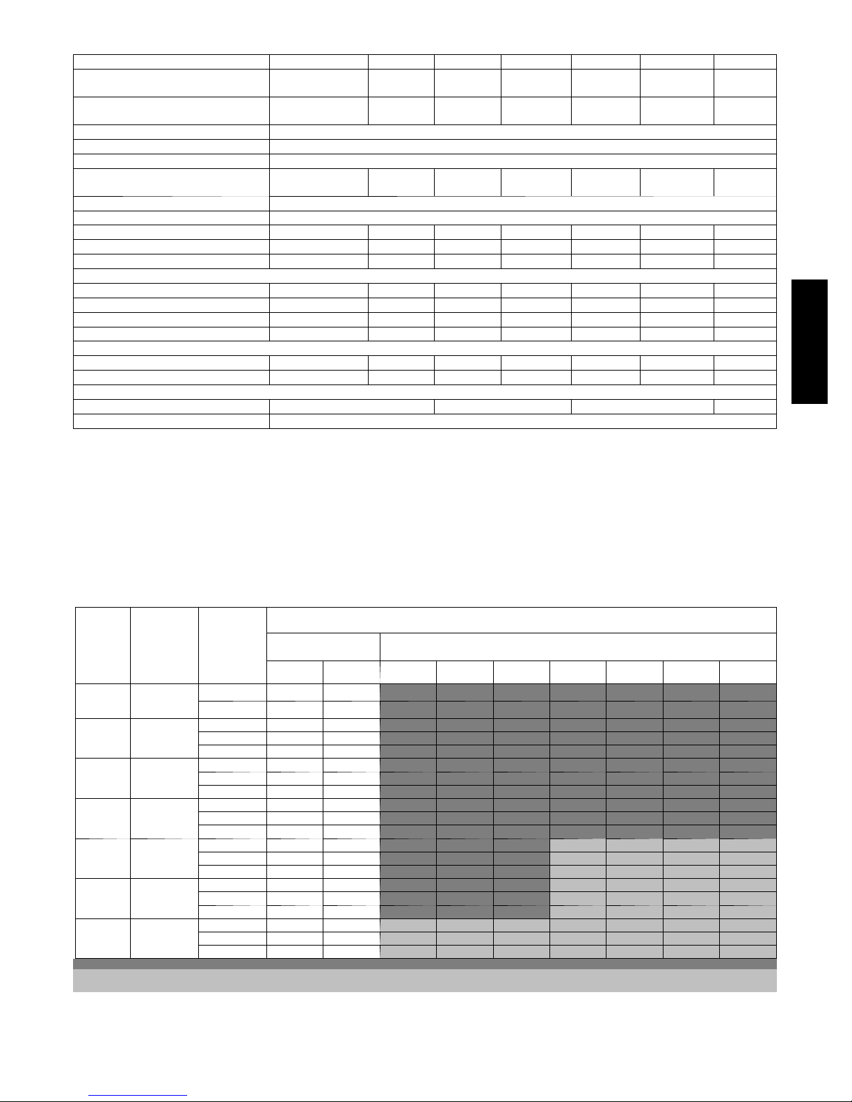
VAPOR LINE SIZING AND COOLING CAPACITY LOSS
LONG LINE APPLICATION: An application is considered ”Long
line” when the total equivalent tubing length exceeds 80 ft. (24.38
m) or when there is more than 20 ft. (6.09 m) vertical separation
between indoor and outdoor units. These applications require
additional accessories and system modifications for reliable system
operation. The maximum allowable total equivalent length is 250
ft. (76.2 m). The maximum vertical separation is 200 ft. (60.96 m)
Unit Nomi-
nal Size
(Btuh)
18000
1Stage
Puron AC
24000
1Stage
Puron AC
30000
1Stage
Puron AC
36000
1Stage
Puron AC
42000
1Stage
Puron AC
48000
1Stage
Puron AC
60000
1Stage
Puron AC
Applications in this area are long line. Accessories are required as shown recommended on Long Line Application Guidelines
Applications in this area may have height restrictions that limit allowable total equivalent length, when outdoor unit is below indoor unit See Long Line Application Guidelines
Maximum
Liquid Line
Diameters
(In. OD)
3/8
3/8
3/8
3/8
3/8
3/8
3/8
Vapo r Li ne
Diameters
(In. OD)
1/2 1 2 3 4 6 7 8 9 10
5/8 0 0 1 1 1 2 2 3 3
5/8 0 1 1 2 3 3 4 4 5
3/4 0 0 0 0 1 1 1 1 1
7/8 0 0 0 0 0 0 0 0 0
5/8 1 2 3 3 4 5 6 7 8
3/4 0 0 1 1 1 2 2 2 3
7/8 0 0 0 0 1 1 1 1 1
5/8 1 2 4 5 6 7 9 10 11
3/4 0 0 1 1 2 2 3 3 4
7/8 0 0 0 0 1 1 1 1 2
3/4 0 1 2 2 3 4 4 5 6
7/8 0 0 1 1 1 2 2 2 3
11/8 0 0 0 0 0 0 0 0 0
3/4 0 1 2 3 4 5 5 6 7
7/8 0 0 1 1 2 2 2 3 3
11/8 0 0 0 0 0 0 0 1 1
3/4 1 2 4 5 6 7 9 10 11
7/8 0 1 2 2 3 4 4 5 5
11/8 0 0 0 1 1 1 1 1 1
Standard
Application
26--- 50
(7.9---15.2)
51--- 80
(15.5---24.4)
81--- 100
(24.7---30.5)
when outdoor unit is above indoor unit, and 80 ft. (24.38 m) when
the outdoor unit is below the indoor unit. Refer to Accessory
Usage Guideline below for required accessories. See Longline
Application Guideline for required piping and system
modifications. Also, refer to the table below for the vapor tube
diameters based on the total length to minimize the cooling
capacity loss.
Cooling Capacity Loss (%)
Total Equivalent Line Length ft. (m)
Long Line Application Requires Accessories
101--- 125
(30.8---38.1)
126--- 150
(38.4---45.7)
151--- 175
(46.0---53.3)
176--- 200
(53.6---61.0)
201--- 225
(61.3---68.6)
226--- 250
(68.9---76.2)
3
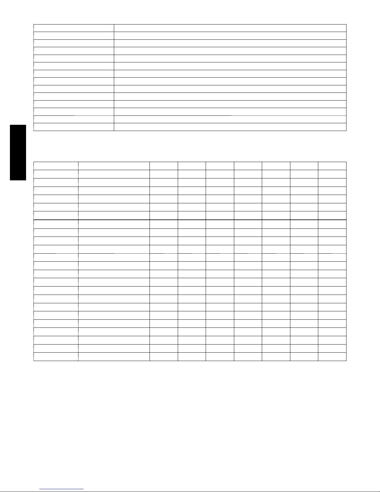
ACCESSORY THERMOSTATS
THERMOSTAT / SUBBASE PKG. DESCRIPTION
T 6 --- P R H --- 0 1 Programmable Thermidistat
T 6 --- N R H --- 0 1 Non ---programmable Thermidistat
T 1 --- PA C --- 0 1 Legacy RNC Series Programmable AC Stat
T 1 --- N A C --- 0 1 Legacy RNC Series Non --- programmable AC Stat
TSTATBBPRH01 --- B Thermidistat Control --- Programmable / Non ---Programmable Thermostat with Humidity control
TSTATBBPAC01 --- B T he rm o st a t --- A u t o C h an ge o v e r, 7 --- D a y P r o g r am m ab le , _F/_C , 1 --- S t ag e H e at , 1 --- S ta g e C oo l
TSTATBBNAC01--- C T h e rm o st a t --- A u t o C h a n g e ov e r , N o n --- P r o gr a m m ab l e , _F/_C , 1 --- S ta g e H e a t , 1 --- S t ag e C o ol
TSTATBBBAC01 --- B Builder’s Thermostat --- Manual Changeover, Non--- Programmable, _F/_C , 1 --- S t a ge H e a t, 1 --- S ta g e C oo l
TSTATBBSEN01---B Outdoor Air Temperature Sensor
TSTATXXBBP01 Backplate for Builder’s Thermostat
TSTATXXNBP01 Backplate for Non --- Programmable Thermostat
TSTATXXPBP01 Backplate for Programmable Thermostat
TSTATXXCNV10 Thermostat Conversion Kit (4 to 5 wires) -- - 10 Pack
ACCESSORIES
114A
KIT NUMBER DESCRIPTION 018 --- C 024--- D 030--- D 036--- C 042---D 048 --- D 060 --- D
HC32GE229 MOTOR FAN BALL BEARING X X X
HC38GE228 MOTOR FAN BALL BEARING X X
HC40GE228 MOTOR FAN BALL BEARING X X
KAACH1401AAA CRANKCASE HTR X X X X
KAACH1201AAA CRANKCASE HTR X X X
KAACS0201PTC START ASSIST PTC X X X X X X X
KAAFT0101AAA FREEZE THERMOSTAT X X X X X X X
KAAHI0501PUR HIGH PRESSURE SWITCH X X X X X X X
KAALP0401PUR LOW PRESSURE SWITCH X X X X X X X
KAALS0201LLS SOL VALVE X X X X X X X
KAATD0101TDR TIME DELAY RELAY X X X X X X X
KAAWS0101AAA WINTER START X X X X X X X
KSACY0101AAA CYCLE PROTECTOR X X X X X X X
KSAHS1701AAA HARD START (CAP / RELAY) X X X X X X X
KSALA0301410 LOW AMBIENT PSW X X X X X X X
KSALA0601AAA MOTORMASTER 230V X X X X X X X
KSASF0101AAA SUPPORT FEET X X X X X X X
KSASH0601COP SOUND HOOD X X X X X X
KSASH2101COP SOUND HOOD X
KSATX0201PUR TXV PURON HSO X X X
KSATX0301PUR TXV PURON HSO X X
KSATX0401PUR TXV PURON HSO X
KSATX0501PUR TXV PURON HSO X
x = Accessory
4
ACCESSORY USAGE GUIDELINE
REQUIRED FOR LOW--- AMBI-
ACCESSORY
Ball Bearing Fan Motor Yes{ No No
Compressor Start Assist Capacitor and Relay Yes Yes No
Crankcase Heater Yes Yes No
Evaporator Freeze Thermostat Yes No No
H a r d S h u t --- O ff T X V Yes Ye s Yes
Liquid Line Solenoid Valve No No No
Motor Master®Control or
Low--- ambient Pressure Switch
Support Feet Recommended No Recommended
* For tubing line sets between 80 and 200 f t. (24.38 and 60.96 m) and/or 20 ft. (6.09 m) vertical differential, refer to Residential Split---System Longline
Application Guideline.
{ Required for Low ---Ambient Controller (full modulation feature) MotorMasterr Control.
Winter Start Control Yes No No
ENT COOLING APPLICATIONS
(Below 55°F/12.8_C)
Yes No No
REQUIRED FOR LONG
LINE
APPLICATIONS*
(Over 80 ft./24.38 m)
Accessory Description and Usage (Listed Alphabetically)
1. Ball--Bearing Fan Motor
A fan motor with ball bearings which permits speed reduction
while maintaining bearing lubrication.
Usage Guideline:
Required on all units when MotorMasterr is used.
2. Compressor Start Assist -- Capacitor and Relay
Start capacitor and relay gives a ”hard” boost to compressor motor
at each start up.
Usage Guideline:
Required for reciprocating compressors in the
following applications:
Long line
Low ambient cooling
Hard shut off expansion valve on indoor coil
Liquid line solenoid on indoor coil
Required for single--phase scroll compressors in the
following applications:
Long line
Low ambient cooling
Suggested for all compressors in areas with a history of
low voltage problems.
3. Compressor Start Assist — PTC Type
Solid state electrical device which gives a ”soft” boost to the
compressor at each start--up.
Usage Guideline:
Suggested in installations with marginal power supply.
4. Crankcase Heater
An electric resistance heater which mounts to the base of the
compressor to keep the lubricant warm during off cycles. Improves
compressor lubrication on restart and minimizes the chance of
liquid slugging.
Usage Guideline:
Required in low ambient cooling applications.
Required in long line applications.
Suggested in all commercial applications.
5. Cycle Protector
The cycle protector is designed to prevent compressor short
cycling. This control provides an approximate 5 --minute delay after
power to the compressor has been interrupted for any reason,
including power outage, protector control trip, thermostat jiggling,
or normal cycling.
6. Evaporator Freeze Thermostat
An SPST temperature--actuated switch that stops unit operation
when evaporator reaches freeze--up conditions.
Usage Guideline:
Required when low ambient kit has been added.
7. Low--Ambient Pressure Switch Kit
A long life pressure switch which is mounted to outdoor unit
service valve. It is designed to cycle the outdoor fan motor in order
to maintain head pressure within normal operating limits
(approximately 100 psig to 225 psig). The control will maintain
working head pressure at low--ambient temperatures down to 0_F
(--18_C) when properly installed.
Usage Guideline:
A Low--Ambient Pressure Switch or MotorMasterr
Low-- Ambient Controller must be used when cooling operation is
used at outdoor temperatures below 55_F (12.8_C).
8. MotorMasterr Low--Ambient Controller
A fan-- speed control device activated by a temperature sensor,
designed to control condenser fan motor speed in response to the
saturated, condensing temperature during operation in cooling
mode only. For outdoor temperatures down to --20_F (--28.9_C), it
maintains condensing temperature at 100_F ±10_F (37.8_C ±
5.5_C).
Usage Guideline:
A MotorMasterr Low Ambient Controller or
Low-- Ambient Pressure Switch must be used when
cooling operation is used at outdoor temperatures
below 55_F (12.8_C).
Suggested for all commercial applications.
9. Outdoor Air Temperature Sensor
Designed for use with Bryant Thermostats listed in this
publ
i
cation. This device enables the thermostat to display the
outdoor temperature. This device also
is required to enable special thermostat features such as auxiliary
heat lock out.
Usage Guideline:
Suggested for all Bryant thermostats listed in this
publication.
REQUIRED FOR
SEA COAST
APPLICATIONS
(Within2miles/3.22km)
114A
5

Accessory Description and Usage (Listed Alphabetically) (Continued)
10. Sound Hood
Wraparound sound reducing cover for the compressor. Reduces the
sound level by about 2 dBA.
Usage Guideline:
Suggested when unit is installed closer than 15 ft (4.57 m) to
quiet areas, bedrooms, etc.
Suggested when unit is installed between two houses less
than 10 ft (3.05 m) apart.
11. Support Feet
Four stick --on plastic feet that raise the unit 4 in. (101.6 mm) above
the mounting pad. This allows sand, dirt, and other debris to be
flushed from the unit base, minimizing corrosion.
Usage Guideline:
Suggested in the following applications:
Coastal installations.
Windy areas or where debris is normally circulating.
Rooftop installations.
For improved sound ratings.
114A
12. Thermostatic Expansion Valve (TXV)
A modulating flow--control valve which meters refrigerant liquid
flow rate into the evaporator in response to the superheat of the
refrigerant gas leaving the evaporator.
Kit includes valve, adapter tubes, and external equalizer tube. Hard
shut off types are available.
NOTE: When using a hard shut off TXV with single phase
reciprocating compressors, a Compressor Start Assist Capacitor
and Relay is required.
Usage Guideline:
Required to achieve ARI ratings in certain equipment
combinations. Refer to combination ratings.
Hard shut off TXV or LLS required in air conditioner
long line applications.
Required for use on all zoning systems.
13. Time--Delay Relay
An SPST delay relay which briefly continues operation of indoor
blower motor to provide additional cooling after the compressor
cycles off.
NOTE: Most indoor unit controls include this feature. For those
that do not, use the guideline below.
14. Winter Start Control
This control is designed to alleviate nuisance opening of the
low--pressure switch by bypassing it for the first 3 minutes of
operation.
Usage Guideline:
For improved efficiency ratings for certain
combinations of indoor and outdoor units. Refer to
ARI Unitary Directory.
6
ELECTRICAL DATA
OPER
UNIT SIZE V/PH
018 -- C
024 -- D 58.3 13.5 0.5 17.3 14 14 46 (14.0) 43 (13.1) 30
030 -- D 73.0 14.1 0.5 18.1 14 14 44 (13.4) 41 (12.5) 30
036 -- C 79.0 16.7 1.2 22.0 12 12 57 (17.4) 54 (16.5) 35
042 -- D 112.0 17.9 1.2 23.6 10 10 85 (26.0) 80 (24.4) 40
048 -- D 117.0 21.8 1.2 28.4 10 10 70 (21.3) 67 (20.4) 40
060 -- D 134.0 26.4 1.2 34.2 8 8 91 (27.7) 86 (26.2) 50
* Permissible limits of the voltage r ange at which the unit will operate satisfactorily
{ If wire is applied at ambient greater than 30° C (86° F), consult table 310---16 of the NEC (ANSI/NFPA 70). The ampacity of non ---metallic ---sheathed cable
(NM), trade name ROMEX, shall be that of 60° C conditions, per the NEC (ANSI/NFPA 70) Article 336---26. If other than uncoated (no---plated), 60 or 75° C
insulation, copper wire (solid wire for 10 AWG or smaller, stranded wire for larger than 10 AWG) is used, consult applicable tables of the NEC (ANSI/NFPA 70).
} Length shown is as measured 1 way along wire path between unit and service panel for voltage drop not to exceed 2%.
* * T i me --- De la y f use .
FLA --- F u l l L oa d A m ps
LRA --- L oc ke d R o t or A m ps
MCA --- Minimum Circuit Amps
RLA ---RatedLoadAmps
NOTE: Control circuit is 24---V on all units and requires external power source. Copper wire must be used from service disconnect to unit.
All motors/compressors contain internal overload protection.
208/230/1---60 253 197
VOLTS*
MAX MIN LRA RLA FLA
COMPR FAN
48.0 9.0 0.5 11.7 14 14 67 (20.4) 64 (19.5) 15
MCA
MIN WIRE
SIZE{
60° C
MIN WIRE
SIZE{
75° C
MAX
LENGTH
ft (m)}
60° C
MAX
LENGTH
ft (m)}
75° C
MAX FUSE**
or CKT BRK
AMPS
A--WEIGHTED SOUND POWER LEVEL (dBA)
UNIT SIZE --
SERIES
018 -- C 76 56.0 60.0 65.0 72.0 65.0 60.5 53.5
024 -- D 76 50.5 61.5 68.0 67.5 64.0 60.0 53.5
030 -- D 76 52.0 62.5 71.0 69.0 65.0 62.0 59.5
036 -- C 76 52.0 60.0 65.5 69.5 64.0 63.0 56.0
042 -- D 77 55.0 62.0 66.0 70.5 65.5 60.0 54.0
048 -- D 78 51.5 62.0 67.5 73.5 69.0 64.5 62.0
060 -- D 78 57.0 62.5 69.0 73.0 66.0 62.0 57.5
NOTE: Tested in accordance with ARI Standard 270 ---95 (not listed in ARI).
STANDARD RATING
(dBA)
125 250 500 1000 2000 4000 8000
TYPICAL OCTAVE BAND SPECTRUM (dBA, without tone adjustment)
114A
A--WEIGHTED SOUND POWER LEVEL (dBA) WITH ACCESSORY SOUND HOOD
UNIT SIZE --
SERIES
018 -- C 74 56.0 60.0 65.0 69.0 63.0 60.0 52.5
024 -- D 74 51.5 61.0 67.5 66.5 63.0 59.0 51.5
030 -- D 74 53.0 62.0 68.5 68.0 64.5 61.0 56.0
036 -- C 75 52.0 62.0 65.5 67.5 63.0 61.0 53.5
042 -- D 74 55.0 61.5 65.0 68.5 65.0 59.0 52.0
048 -- D 76 53.0 61.5 67.5 72.0 68.0 61.5 59.0
060 -- D 75 57.0 62.5 68.5 71.0 65.0 60.5 58.5
NOTE: Tested in accordance with ARI Standard 270 ---95 (not listed in ARI).
STANDARD RATING
(dBA)
125 250 500 1000 2000 4000 8000
TYPICAL OCTAVE BAND SPECTRUM (dBA, without tone adjustment)
CHARGING SUBCOOLING (TXV--TYPE EXPANSION DEVICE)
UNIT SIZE --- SERIES REQUIRED SUBCOOLING _F(_C)
018 --- C 10 (5.6)
024 --- D 10 (5.6)
030 --- D 11 (6.1)
036 --- C 10 (5.6)
042 --- D 8 (4.4)
048 --- D 8 (4.4)
060 --- D 9 (5.0)
7
114A
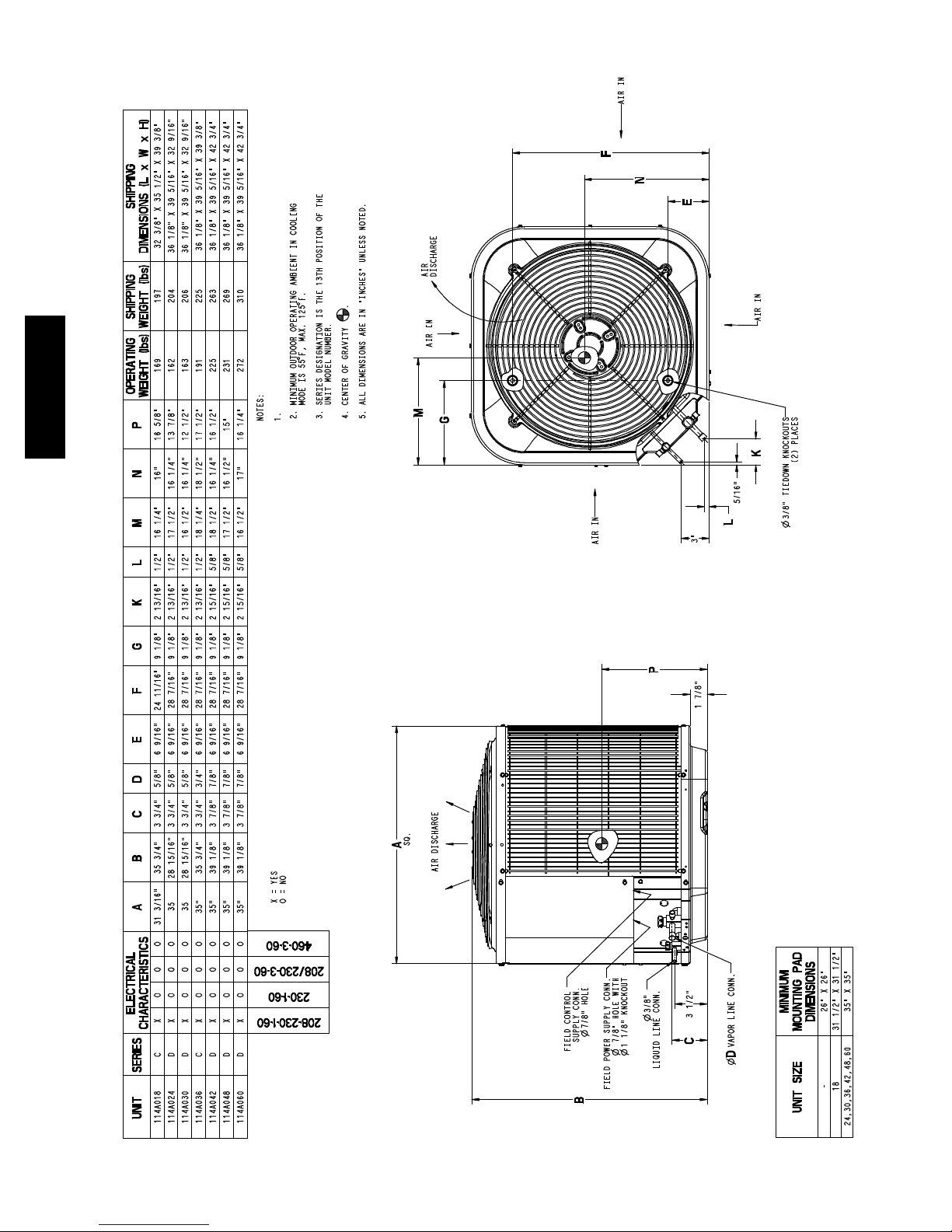
Allow 24” betw een units or 18” if no overh ang within 12 ft.
DIMENSIONS -- ENGLISH
8
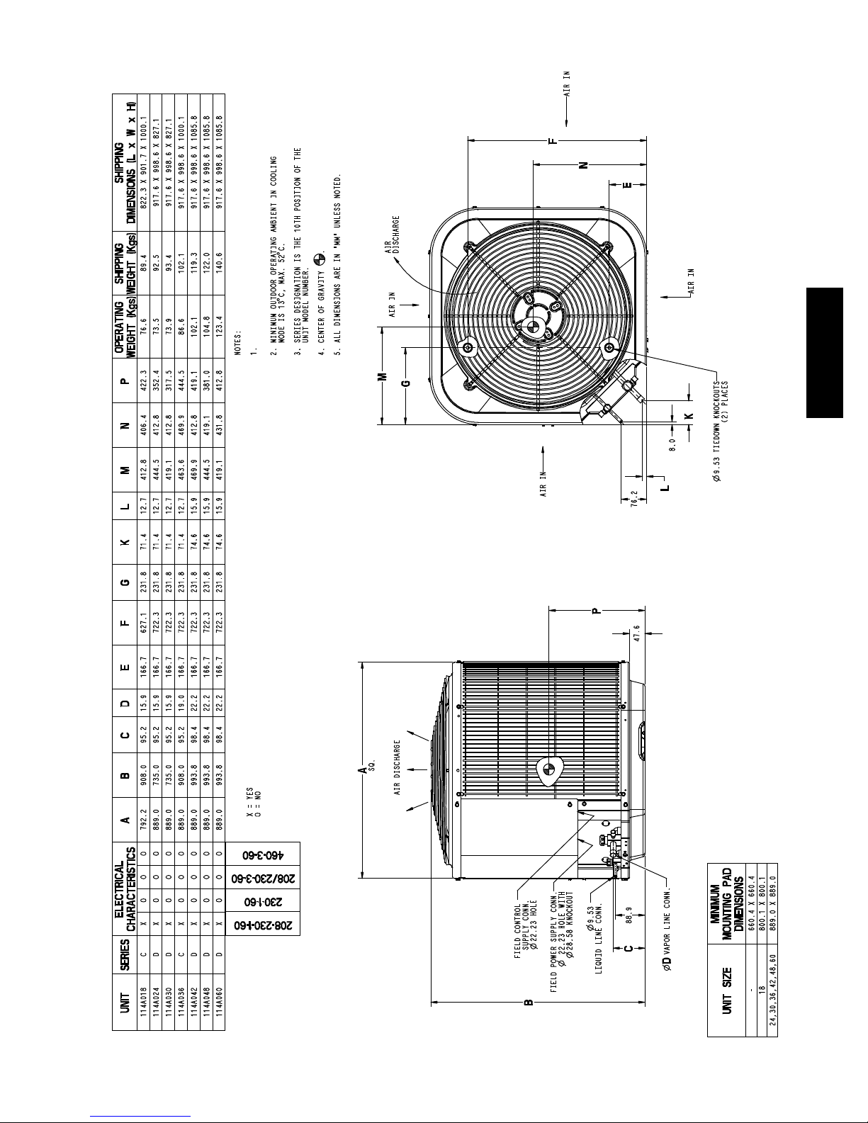
Allow 609.6 mm between units or 457.2 mm ifno overhang
within 3 .7 m.
114A
DIMENSIONS -- SI
9
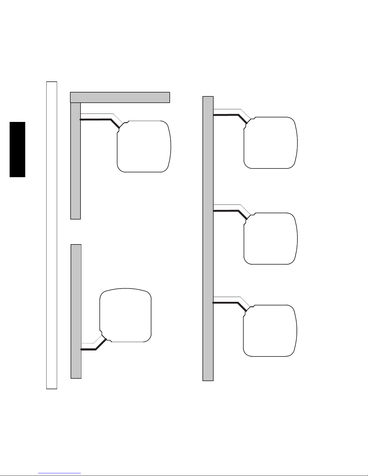
Wall
6”
(152.4)
114A
24”
Wall
(609.6)
CLEARANCES
Clearances (various examples)
6”
Wall
(152.4)
Service
12”
(304.8)
12”
(304.8)
12”
(304.8)
12”
(304.8)
Wall
24”
(609.6)
24”
(609.6)
Service
18”
(457.2)
Service
18”
(457.2)
24”
(609.6)
Service
10
24”
(609.6)
Service
18”
(457.2)
Note: Numbers in ( ) = mm
COMBINATION RATINGS
ARI Ref. No. Model Number Indoor Model Furnace Mo de l Capacity EER SEER Phase
3042449 114ANA018---C {CAP**2414A**+TDR 18000 11.50 14.00 1
3042483 114ANA018---C CAP**1814A** 313*AV024045 17900 12.50 15.00 1
3042451 114ANA018---C CAP**1814A** 315(A,J)AV036070 17600 12.50 15.00 1
3042450 114ANA018---C CAP**1814A**+T DR 17800 11.20 13.50 1
3042484 114ANA018---C CAP**2414A** 313*AV024045 18000 13.00 15.50 1
3042452 114ANA018---C CAP**2414A** 315(A,J)AV036070 17900 13.00 15.00 1
3042455 114ANA018---C CAP**2417A** 315(A,J)AV048090 17900 13.00 15.00 1
3099797 114ANA018---C CAP**2417A** 353AAV036040 18000 13.00 15.50 1
3099798 114ANA018---C CAP**2417A** 353AAV036060 18000 13.00 15.50 1
3042454 114ANA018---C CAP**2417A** 355(A,C)AV042060 17900 13.00 15.00 1
3042453 114ANA018---C CAP**2417A**+T DR 18000 11.50 14.00 1
3042469 114ANA018---C CNPF*2418A**+TDR 18000 11.50 14.00 1
3042487 114ANA018---C CNPH*2417A** 313*AV024045 18000 13.00 15.50 1
3042467 114ANA018---C CNPH*2417A** 315(A,J)AV036070 17900 13.00 15.00 1
3042468 114ANA018---C CNPH*2417A** 315(A,J)AV048090 17900 13.00 15.00 1
3099801 114ANA018---C CNPH*2417A** 353AAV036040 18000 13.00 15.50 1
3099802 114ANA018---C CNPH*2417A** 353AAV036060 18000 13.00 15.50 1
3042464 114ANA018---C CNPH*2417A** 355(A ,C)AV042040 17900 13.00 15.00 1
3042465 114ANA018---C CNPH*2417A** 355(A ,C)AV042060 17900 13.00 15.00 1
3042466 114ANA018---C CNPH*2417A** 355(A ,C)AV042080 17900 13.00 15.00 1
3042463 114ANA018---C CNPH*2417A**+TDR 18000 11.50 14.00 1
3042485 114ANA018---C CNPV*1814A** 313*AV024045 17900 12.50 15.00 1
3042457 114ANA018---C CNPV*1814A** 315(A,J)AV036070 17600 12.50 15.00 1
3042456 114ANA018---C CNPV*1814A**+TDR 17800 11.20 13.50 1
3042486 114ANA018---C CNPV*2414A** 313*AV024045 18000 13.00 15.50 1
3042459 114ANA018---C CNPV*2414A** 315(A,J)AV036070 17900 13.00 15.00 1
3042458 114ANA018---C CNPV*2414A**+TDR 18000 11.50 14.00 1
3042462 114ANA018---C CNPV*2417A** 315(A,J)AV048090 17900 13.00 15.00 1
3099799 114ANA018---C CNPV*2417A** 353AAV036040 18000 13.00 15.50 1
3099800 114ANA018---C CNPV*2417A** 353AAV036060 18000 13.00 15.50 1
3042461 114ANA018---C CNPV*2417A** 355(A,C) AV042060 17900 13.00 15.00 1
3042460 114ANA018---C CNPV*2417A**+TDR 18000 11.50 14.00 1
3042488 114ANA018---C CSPH*2412A** 313*AV024045 18000 13.00 15.50 1
3042474 114ANA018---C CSPH*2412A** 315(A,J)AV036070 17900 13.00 15.00 1
3042475 114ANA018---C CSPH*2412A** 315(A,J)AV048090 17900 13.00 15.00 1
3099803 114ANA018---C CSPH*2412A** 353AAV036040 18000 13.00 15.50 1
3099804 114ANA018---C CSPH*2412A** 353AAV036060 18000 13.00 15.50 1
3042471 114ANA018---C CSPH*2412A** 355(A,C)AV042040 17900 13.00 15.00 1
3042472 114ANA018---C CSPH*2412A** 355(A,C)AV042060 17900 13.00 15.00 1
3042473 114ANA018---C CSPH*2412A** 355(A,C)AV042080 17900 13.00 15.00 1
3042470 114ANA018---C C SPH*2412A**+TDR 18000 12.00 14.00 1
3042480 114ANA018---C FF1ENP018 17800 11.20 13.50 1
3042481 114ANA018---C FF1ENP024 18000 11.20 13.50 1
3042482 114ANA018---C FV4BNF002 18200 13.20 15.00 1
3042478 114ANA018---C FX4CNF018 18000 13.00 15.00 1
3042479 114ANA018---C FX4CNF024 18300 13.00 15.00 1
3042476 114ANA018---C FY4ANF018 17800 11.20 13.50 1
3042477 114ANA018---C FY4ANF024 17900 11.20 13.50 1
114A
3042489 114ANA024---D {CAP**2414A**+TDR 23200 11.70 14.00 1
3042569 114ANA024---D CAP**2414A** 313*AV024045 23200 13.00 15.50 1
3042490 114ANA024---D CAP**2414A** 315(A,J)AV036070 23000 13.00 15.00 1
3042493 114ANA024---D CAP**2417A** 315(A,J)AV048090 23000 13.00 15.00 1
3099805 114ANA024---D CAP**2417A** 353AAV036040 23200 13.00 15.50 1
3099806 114ANA024---D CAP**2417A** 353AAV036060 23200 13.00 15.50 1
3099807 114ANA024---D CAP**2417A** 353AAV036080 23200 13.00 15.50 1
3042492 114ANA024---D CAP**2417A** 355(A,C)AV042060 23000 13.00 15.00 1
3042491 114ANA024---D CAP**2417A**+TDR 23200 11.70 14.00 1
3042570 114ANA024---D CAP**3014A** 313*AV024045 23400 13.00 15.50 1
3042495 114ANA024---D CAP**3014A** 315(A,J)AV036070 23200 13.00 15.00 1
3042494 114ANA024---D CAP**3014A**+TDR 23400 12.00 14.00 1
3042498 114ANA024---D CAP**3017A** 315(A,J)AV048090 23200 13.20 15.00 1
3099808 114ANA024---D CAP**3017A** 353AAV036040 23200 13.00 15.50 1
3099809 114ANA024---D CAP**3017A** 353AAV036060 23200 13.00 15.50 1
3099810 114ANA024---D CAP**3017A** 353AAV036080 23200 13.00 15.50 1
3042497 114ANA024---D CAP**3017A** 355(A,C)AV042060 23200 13.00 15.00 1
3042496 114ANA024---D CAP**3017A**+TDR 23400 12.00 14.00 1
3042533 114ANA024---D CNPF*2418A**+TDR 23200 11.70 14.00 1
3042573 114ANA024---D CNPH*2417A** 313*AV024045 23000 12.50 15.50 1
3042516 114ANA024---D CNPH*2417A** 315(A,J) AV036070 22800 13.00 15.00 1
3042517 114ANA024---D CNPH*2417A** 315(A,J) AV048090 23000 13.00 15.00 1
3042518 114ANA024---D CNPH*2417A** 315(A,J) AV060110 23000 13.00 15.00 1
3042519 114ANA024---D CNPH*2417A** 315(A,J) AV066135 23000 13.00 15.00 1
* Tested combination
11

COMBINATION RATINGS CONTINUED
ARI Ref. No. Model Number Indoor Model Furnace Mo de l Capacity EER SEER Phase
3042520 114ANA024---D CNPH*2417A** 315(A,J) AV066155 23000 13.00 15.00 1
3099817 114ANA024---D CNPH*2417A** 353AAV036040 23200 13.00 15.50 1
3099818 114ANA024---D CNPH*2417A** 353AAV036060 23200 13.00 15.50 1
3099819 114ANA024---D CNPH*2417A** 353AAV036080 23200 13.00 15.50 1
3042510 114ANA024---D CNPH*2417A** 355(A,C)AV042040 23000 13.00 15.00 1
3042511 114ANA024---D CNPH*2417A** 355(A,C)AV042060 23000 13.00 15.00 1
3042512 114ANA024---D CNPH*2417A** 355(A,C)AV042080 23000 13.00 15.00 1
3042513 114ANA024---D CNPH*2417A** 355(A,C)AV060080 22800 12.50 15.00 1
3042514 114ANA024---D CNPH*2417A** 355(A,C)AV060100 23000 13.00 15.00 1
3042515 114ANA024---D CNPH*2417A** 355(A,C)AV060120 22800 12.50 15.00 1
3042509 114ANA024---D CNPH*2417A**+TDR 23200 11.70 14.00 1
3042574 114ANA024---D CNPH*3017A** 313*AV024045 23400 13.00 15.50 1
3042528 114ANA024---D CNPH*3017A** 315(A,J) AV036070 23200 13.00 15.00 1
3042529 114ANA024---D CNPH*3017A** 315(A,J) AV048090 23200 13.20 15.00 1
3042530 114ANA024---D CNPH*3017A** 315(A,J) AV060110 23200 13.00 15.00 1
3042531 114ANA024---D CNPH*3017A** 315(A,J) AV066135 23400 13.00 15.00 1
3042532 114ANA024---D CNPH*3017A** 315(A,J) AV066155 23400 13.20 15.00 1
3099820 114ANA024---D CNPH*3017A** 353AAV036040 23200 13.00 15.50 1
3099821 114ANA024---D CNPH*3017A** 353AAV036060 23200 13.00 15.50 1
3099822 114ANA024---D CNPH*3017A** 353AAV036080 23200 13.00 15.50 1
3042522 114ANA024---D CNPH*3017A** 355(A,C)AV042040 23200 13.00 15.00 1
114A
3042523 114ANA024---D CNPH*3017A** 355(A,C)AV042060 23200 13.00 15.00 1
3042524 114ANA024---D CNPH*3017A** 355(A,C)AV042080 23200 13.00 15.00 1
3042525 114ANA024---D CNPH*3017A** 355(A,C)AV060080 23000 13.00 15.00 1
3042526 114ANA024---D CNPH*3017A** 355(A,C)AV060100 23200 13.00 15.00 1
3042527 114ANA024---D CNPH*3017A** 355(A,C)AV060120 23200 13.00 15.00 1
3042521 114ANA024---D CNPH*3017A**+TDR 23400 12.00 14.00 1
3042571 114ANA024---D CNPV*2414A** 313*AV024045 23000 12.50 15.50 1
3042500 114ANA024---D CNPV*2414A** 315(A,J)AV036070 22800 13.00 15.00 1
3042499 114ANA024---D CNPV*2414A**+TDR 23200 11.70 14.00 1
3042503 114ANA024---D CNPV*2417A** 315(A,J)AV048090 23000 13.00 15.00 1
3099811 114ANA024---D CNPV*2417A** 353AAV036040 23200 13.00 15.50 1
3099812 114ANA024---D CNPV*2417A** 353AAV036060 23200 13.00 15.50 1
3099813 114ANA024---D CNPV*2417A** 353AAV036080 23200 13.00 15.50 1
3042502 114ANA024---D CNPV*2417A** 355(A,C )AV042060 23000 13.00 15.00 1
3042501 114ANA024---D CNPV*2417A**+TDR 23200 11.70 14.00 1
3042572 114ANA024---D CNPV*3014A** 313*AV024045 23400 13.00 15.50 1
3042505 114ANA024---D CNPV*3014A** 315(A,J)AV036070 23200 13.00 15.00 1
3042504 114ANA024---D CNPV*3014A**+TDR 23400 12.00 14.00 1
3042508 114ANA024---D CNPV*3017A** 315(A,J)AV048090 23200 13.20 15.00 1
3099814 114ANA024---D CNPV*3017A** 353AAV036040 23200 13.00 15.50 1
3099815 114ANA024---D CNPV*3017A** 353AAV036060 23200 13.00 15.50 1
3099816 114ANA024---D CNPV*3017A** 353AAV036080 23200 13.00 15.50 1
3042507 114ANA024---D CNPV*3017A** 355(A,C )AV042060 23200 13.00 15.00 1
3042506 114ANA024---D CNPV*3017A**+TDR 23400 12.00 14.00 1
3042575 114ANA024---D CSPH*2412A** 313*AV024045 23000 12.50 15.50 1
3042541 114ANA024---D CSPH*2412A** 315(A,J)AV036070 23000 13.00 15.00 1
3042542 114ANA024---D CSPH*2412A** 315(A,J)AV048090 23000 13.00 15.00 1
3042543 114ANA024---D CSPH*2412A** 315(A,J)AV060110 23200 13.00 15.00 1
3042544 114ANA024---D CSPH*2412A** 315(A,J)AV066135 23200 13.00 15.00 1
3042545 114ANA024---D CSPH*2412A** 315(A,J)AV066155 23200 13.00 15.00 1
3099823 114ANA024---D CSPH*2412A** 353AAV036040 23200 13.00 15.50 1
3099824 114ANA024---D CSPH*2412A** 353AAV036060 23200 13.00 15.50 1
3099825 114ANA024---D CSPH*2412A** 353AAV036080 23200 13.00 15.50 1
3042535 114ANA024---D CSPH*2412A** 355(A,C)AV042040 23200 13.00 15.00 1
3042536 114ANA024---D CSPH*2412A** 355(A,C)AV042060 23000 13.00 15.00 1
3042537 114ANA024---D CSPH*2412A** 355(A,C)AV042080 23200 13.00 15.00 1
3042538 114ANA024---D CSPH*2412A** 355(A,C)AV060080 23000 13.00 15.00 1
3042539 114ANA024---D CSPH*2412A** 355(A,C)AV060100 23200 13.00 15.00 1
3042540 114ANA024---D CSPH*2412A** 355(A,C)AV060120 23200 13.00 15.00 1
3042534 114ANA024---D C SPH*2412A**+TDR 23200 11.70 14.00 1
3042576 114ANA024---D CSPH*3012A** 313*AV024045 23400 13.00 15.50 1
3042553 114ANA024---D CSPH*3012A** 315(A,J)AV036070 23200 13.00 15.00 1
3042554 114ANA024---D CSPH*3012A** 315(A,J)AV048090 23200 13.20 15.00 1
3042555 114ANA024---D CSPH*3012A** 315(A,J)AV060110 23400 13.00 15.00 1
3042556 114ANA024---D CSPH*3012A** 315(A,J)AV066135 23400 13.00 15.00 1
3042557 114ANA024---D CSPH*3012A** 315(A,J)AV066155 23400 13.00 15.00 1
3099826 114ANA024---D CSPH*3012A** 353AAV036040 23200 13.00 15.50 1
3099827 114ANA024---D CSPH*3012A** 353AAV036060 23200 13.00 15.50 1
3099828 114ANA024---D CSPH*3012A** 353AAV036080 23200 13.00 15.50 1
3042547 114ANA024---D CSPH*3012A** 355(A,C)AV042040 23400 13.00 15.00 1
3042548 114ANA024---D CSPH*3012A** 355(A,C)AV042060 23200 13.00 15.00 1
3042549 114ANA024---D CSPH*3012A** 355(A,C)AV042080 23200 13.00 15.00 1
* Tested combination
12

COMBINATION RATINGS CONTINUED
ARI Ref. No. Model Number Indoor Model Furnace Mo de l Capacity EER SEER Phase
3042550 114ANA024---D CSPH*3012A** 355(A,C)AV060080 23000 13.00 15.00 1
3042551 114ANA024---D CSPH*3012A** 355(A,C)AV060100 23400 13.00 15.00 1
3042552 114ANA024---D CSPH*3012A** 355(A,C)AV060120 23200 13.00 15.00 1
3042546 114ANA024---D C SPH*3012A**+TDR 23400 12.00 14.00 1
3042563 114ANA024---D FE4AN(B,F)003+UI 23600 13.20 15.00 1
3042562 114ANA024---D FE4ANF002+UI 23400 13.20 15.00 1
3042564 114ANA024---D FE5ANB004+UI 24200 13.20 15.00 1
3042567 114ANA024---D FF1ENP024 23000 11.70 13.50 1
3042568 114ANA024---D FF1ENP030 23000 11.70 13.50 1
3042566 114ANA024---D FV4BN(B,F)003 23600 13.20 15.00 1
3042565 114ANA024---D FV4BNF002 23400 13.20 15.00 1
3042560 114ANA024---D FX4CNF024 23400 12.50 15.00 1
3042561 114ANA024---D FX4CNF030 23600 13.00 15.00 1
3042558 114ANA024---D FY4ANF024 23000 11.40 14.00 1
3042559 114ANA024---D FY4ANF030 23200 12.00 14.00 1
3042577 114ANA030---D {CAP**3014A**+TDR 29000 11.70 14.00 1
3042578 114ANA030---D CAP**3014A** 315(A,J)AV036070 28800 12.50 15.00 1
3042667 114ANA030---D CAP**3017A** 313*AV048070 29000 12.50 15.00 1
3042581 114ANA030---D CAP**3017A** 315(A,J)AV048090 28800 12.50 15.00 1
3099829 114ANA030---D CAP**3017A** 353AAV036040 29000 13.00 15.50 1
3099830 114ANA030---D CAP**3017A** 353AAV036060 29000 13.00 15.50 1
3099831 114ANA030---D CAP**3017A** 353AAV036080 29000 13.00 15.50 1
3099832 114ANA030---D CAP**3017A** 353AAV048080 29000 12.70 15.50 1
3042580 114ANA030---D CAP**3017A** 355(A,C)AV042060 28800 12.50 15.00 1
3042579 114ANA030---D CAP**3017A**+TDR 29000 11.70 14.00 1
3042583 114ANA030---D CAP**3614A** 315(A,J)AV036070 28800 12.50 15.00 1
3042582 114ANA030---D CAP**3614A**+TDR 28200 11.70 14.00 1
3042668 114ANA030---D CAP**3617A** 313*AV048070 29200 12.50 15.00 1
3042586 114ANA030---D CAP**3617A** 315(A,J)AV048090 29000 13.00 15.00 1
3099833 114ANA030---D CAP**3617A** 353AAV036040 29000 13.00 15.50 1
3099834 114ANA030---D CAP**3617A** 353AAV036060 29000 13.00 15.50 1
3099835 114ANA030---D CAP**3617A** 353AAV036080 29000 13.00 15.50 1
3099836 114ANA030---D CAP**3617A** 353AAV048080 29000 13.00 15.50 1
3042585 114ANA030---D CAP**3617A** 355(A,C)AV042060 28800 12.50 15.00 1
3042584 114ANA030---D CAP**3617A**+TDR 29200 11.70 14.00 1
3042669 114ANA030---D CAP**3621A** 313*AV048090 29400 13.00 15.50 1
3042591 114ANA030---D CAP**3621A** 315(A,J)AV060110 29000 13.00 15.00 1
3042588 114ANA030---D CAP**3621A** 355(A,C)AV042080 28800 12.50 15.00 1
3042589 114ANA030---D CAP**3621A** 355(A,C)AV060080 29000 12.50 15.00 1
3042590 114ANA030---D CAP**3621A** 355(A,C)AV060100 28800 12.50 15.00 1
3042587 114ANA030---D CAP**3621A**+TDR 29200 11.70 14.00 1
3042629 114ANA030---D CNPF*3618A**+TDR 29000 11.70 14.00 1
3042673 114ANA030---D CNPH*3017A** 313*AV048070 29000 12.50 15.00 1
3042674 114ANA030---D CNPH*3017A** 313*AV048090 29000 12.50 15.00 1
3042612 114ANA030---D CNPH*3017A** 315(A,J) AV036070 28800 12.50 15.00 1
3042613 114ANA030---D CNPH*3017A** 315(A,J) AV048090 28800 12.50 15.00 1
3042614 114ANA030---D CNPH*3017A** 315(A,J) AV060110 29000 12.50 15.00 1
3042615 114ANA030---D CNPH*3017A** 315(A,J) AV066135 29000 12.50 15.00 1
3042616 114ANA030---D CNPH*3017A** 315(A,J) AV066155 29000 13.00 15.00 1
3099845 114ANA030---D CNPH*3017A** 353AAV036040 29000 13.00 15.50 1
3099846 114ANA030---D CNPH*3017A** 353AAV036060 29000 12.70 15.50 1
3099847 114ANA030---D CNPH*3017A** 353AAV036080 29000 13.00 15.50 1
3099848 114ANA030---D CNPH*3017A** 353AAV048080 29000 12.70 15.50 1
3042606 114ANA030---D CNPH*3017A** 355(A,C)AV042040 28800 12.50 15.00 1
3042607 114ANA030---D CNPH*3017A** 355(A,C)AV042060 28800 12.50 15.00 1
3042608 114ANA030---D CNPH*3017A** 355(A,C)AV042080 28800 12.50 15.00 1
3042609 114ANA030---D CNPH*3017A** 355(A,C)AV060080 28800 12.50 15.00 1
3042610 114ANA030---D CNPH*3017A** 355(A,C)AV060100 28600 12.50 15.00 1
3042611 114ANA030---D CNPH*3017A** 355(A,C)AV060120 28800 12.50 15.00 1
3042605 114ANA030---D CNPH*3017A**+TDR 29000 11.70 14.00 1
3042675 114ANA030---D CNPH*3617A** 313*AV048070 29000 12.50 15.00 1
3042676 114ANA030---D CNPH*3617A** 313*AV048090 29000 12.50 15.00 1
3042624 114ANA030---D CNPH*3617A** 315(A,J) AV036070 28800 12.50 15.00 1
3042625 114ANA030---D CNPH*3617A** 315(A,J) AV048090 28800 12.50 15.00 1
3042626 114ANA030---D CNPH*3617A** 315(A,J) AV060110 29000 12.50 15.00 1
3042627 114ANA030---D CNPH*3617A** 315(A,J) AV066135 29000 12.50 15.00 1
3042628 114ANA030---D CNPH*3617A** 315(A,J) AV066155 29000 13.00 15.00 1
3099849 114ANA030---D CNPH*3617A** 353AAV036040 29000 13.00 15.50 1
3099850 114ANA030---D CNPH*3617A** 353AAV036060 29000 12.70 15.50 1
3099851 114ANA030---D CNPH*3617A** 353AAV036080 29000 13.00 15.50 1
3099852 114ANA030---D CNPH*3617A** 353AAV048080 29000 12.70 15.50 1
3042618 114ANA030---D CNPH*3617A** 355(A,C)AV042040 28800 12.50 15.00 1
* Tested combination
13
114A

COMBINATION RATINGS CONTINUED
ARI Ref. No. Model Number Indoor Model Furnace Mo de l Capacity EER SEER Phase
3042619 114ANA030---D CNPH*3617A** 355(A,C)AV042060 28800 12.50 15.00 1
3042620 114ANA030---D CNPH*3617A** 355(A,C)AV042080 28800 12.50 15.00 1
3042621 114ANA030---D CNPH*3617A** 355(A,C)AV060080 28800 12.50 15.00 1
3042622 114ANA030---D CNPH*3617A** 355(A,C)AV060100 28600 12.50 15.00 1
3042623 114ANA030---D CNPH*3617A** 355(A,C)AV060120 28800 12.50 15.00 1
3042617 114ANA030---D CNPH*3617A**+TDR 29000 11.70 14.00 1
3042593 114ANA030---D CNPV*3014A** 315(A,J)AV036070 28800 12.50 15.00 1
3042592 114ANA030---D CNPV*3014A**+TDR 29000 11.70 14.00 1
3042670 114ANA030---D CNPV*3017A** 313*AV048070 29000 12.50 15.00 1
3042596 114ANA030---D CNPV*3017A** 315(A,J)AV048090 28800 12.50 15.00 1
3099837 114ANA030---D CNPV*3017A** 353AAV036040 29000 13.00 15.50 1
3099838 114ANA030---D CNPV*3017A** 353AAV036060 29000 12.70 15.50 1
3099839 114ANA030---D CNPV*3017A** 353AAV036080 29000 13.00 15.50 1
3099840 114ANA030---D CNPV*3017A** 353AAV048080 29000 12.70 15.50 1
3042595 114ANA030---D CNPV*3017A** 355(A,C )AV042060 28800 12.50 15.00 1
3042594 114ANA030---D CNPV*3017A**+TDR 29000 11.70 14.00 1
3042671 114ANA030---D CNPV*3617A** 313*AV048070 29000 12.50 15.00 1
3042599 114ANA030---D CNPV*3617A** 315(A,J)AV048090 28800 12.50 15.00 1
3099841 114ANA030---D CNPV*3617A** 353AAV036040 29000 13.00 15.50 1
3099842 114ANA030---D CNPV*3617A** 353AAV036060 29000 12.70 15.50 1
3099843 114ANA030---D CNPV*3617A** 353AAV036080 29000 13.00 15.50 1
114A
3099844 114ANA030---D CNPV*3617A** 353AAV048080 29000 12.70 15.50 1
3042598 114ANA030---D CNPV*3617A** 355(A,C )AV042060 28800 12.50 15.00 1
3042597 114ANA030---D CNPV*3617A**+TDR 29000 11.70 14.00 1
3042672 114ANA030---D CNPV*3621A** 313*AV048090 29000 12.50 15.00 1
3042604 114ANA030---D CNPV*3621A** 315(A,J)AV060110 29000 12.50 15.00 1
3042601 114ANA030---D CNPV*3621A** 355(A,C )AV042080 28800 12.50 15.00 1
3042602 114ANA030---D CNPV*3621A** 355(A,C )AV060080 28800 12.50 15.00 1
3042603 114ANA030---D CNPV*3621A** 355(A,C )AV060100 28600 12.50 15.00 1
3042600 114ANA030---D CNPV*3621A**+TDR 29000 11.70 14.00 1
3042677 114ANA030---D CSPH*3012A** 313*AV048070 29000 12.50 15.00 1
3042678 114ANA030---D CSPH*3012A** 313*AV048090 29000 12.50 15.00 1
3042637 114ANA030---D CSPH*3012A** 315(A,J)AV036070 29000 12.50 15.00 1
3042638 114ANA030---D CSPH*3012A** 315(A,J)AV048090 29000 12.50 15.00 1
3042639 114ANA030---D CSPH*3012A** 315(A,J)AV060110 29000 12.50 15.00 1
3042640 114ANA030---D CSPH*3012A** 315(A,J)AV066135 29000 12.50 15.00 1
3042641 114ANA030---D CSPH*3012A** 315(A,J)AV066155 29000 12.50 15.00 1
3099853 114ANA030---D CSPH*3012A** 353AAV036040 29000 13.00 15.70 1
3099854 114ANA030---D CSPH*3012A** 353AAV036060 29000 12.70 15.50 1
3099855 114ANA030---D CSPH*3012A** 353AAV036080 29000 13.00 15.50 1
3099856 114ANA030---D CSPH*3012A** 353AAV048080 29000 12.70 15.50 1
3042631 114ANA030---D CSPH*3012A** 355(A,C)AV042040 28800 12.50 15.00 1
3042632 114ANA030---D CSPH*3012A** 355(A,C)AV042060 28800 12.50 15.00 1
3042633 114ANA030---D CSPH*3012A** 355(A,C)AV042080 28800 12.50 15.00 1
3042634 114ANA030---D CSPH*3012A** 355(A,C)AV060080 29000 12.50 15.00 1
3042635 114ANA030---D CSPH*3012A** 355(A,C)AV060100 28800 12.50 15.00 1
3042636 114ANA030---D CSPH*3012A** 355(A,C)AV060120 28800 12.50 15.00 1
3042630 114ANA030---D C SPH*3012A**+TDR 29000 11.70 14.00 1
3042679 114ANA030---D CSPH*3612A** 313*AV048070 29200 12.50 15.00 1
3042680 114ANA030---D CSPH*3612A** 313*AV048090 29400 12.50 15.50 1
3042649 114ANA030---D CSPH*3612A** 315(A,J)AV036070 29000 12.50 15.00 1
3042650 114ANA030---D CSPH*3612A** 315(A,J)AV048090 29000 13.00 15.00 1
3042651 114ANA030---D CSPH*3612A** 315(A,J)AV060110 29000 13.00 15.00 1
3042652 114ANA030---D CSPH*3612A** 315(A,J)AV066135 29000 13.00 15.00 1
3042653 114ANA030---D CSPH*3612A** 315(A,J)AV066155 29000 13.00 15.00 1
3099857 114ANA030---D CSPH*3612A** 353AAV036040 29000 13.00 15.50 1
3099858 114ANA030---D CSPH*3612A** 353AAV036060 29000 13.00 15.50 1
3099859 114ANA030---D CSPH*3612A** 353AAV036080 29000 13.00 15.50 1
3099860 114ANA030---D CSPH*3612A** 353AAV048080 29000 13.00 15.50 1
3042643 114ANA030---D CSPH*3612A** 355(A,C)AV042040 29000 12.50 15.00 1
3042644 114ANA030---D CSPH*3612A** 355(A,C)AV042060 29000 13.00 15.00 1
3042645 114ANA030---D CSPH*3612A** 355(A,C)AV042080 29000 12.50 15.00 1
3042646 114ANA030---D CSPH*3612A** 355(A,C)AV060080 29000 13.00 15.00 1
3042647 114ANA030---D CSPH*3612A** 355(A,C)AV060100 29000 13.00 15.00 1
3042648 114ANA030---D CSPH*3612A** 355(A,C)AV060120 29000 13.00 15.00 1
3042642 114ANA030---D C SPH*3612A**+TDR 29200 11.70 14.00 1
3042658 114ANA030---D FE4AN(B,F)003+UI 29200 13.00 15.00 1
3042659 114ANA030---D FE4AN(B,F)005+UI 30000 13.20 15.00 1
3042657 114ANA030---D FE4ANF002+UI 29000 12.50 15.00 1
3042660 114ANA030---D FE5ANB004+UI 30200 13.20 15.00 1
3042661 114ANA030---D FF1ENP030 28600 11.70 14.00 1
3042662 114ANA030---D FF1ENP036 29200 11.70 14.00 1
3042664 114ANA030---D FV4BN(B,F)003 29200 13.00 15.00 1
* Tested combination
14

COMBINATION RATINGS CONTINUED
ARI Ref. No. Model Number Indoor Model Furnace Mo de l Capacity EER SEER Phase
3042665 114ANA030---D FV4BN(B,F)005 30000 13.20 15.00 1
3042663 114ANA030---D FV4BNF002 29000 12.50 15.00 1
3042656 114ANA030---D FX4CN(B,F)036 29400 12.20 14.50 1
3042655 114ANA030---D FX4CNF030 29200 12.50 15.00 1
3042654 114ANA030---D FY4ANF030 28800 11.70 14.00 1
3042666 114ANA030---D FY4ANF036 29000 11.70 13.50 1
3042681 114ANA036---C {CAP**4221A**+TDR 35800 11.50 14.00 1
3042682 114ANA036---C CAP**3614A** 313*AV024045 34200 12.00 14.00 1
3042712 114ANA036---C CAP**3614A** 315(A,J)AV036070 34000 12.50 14.50 1
3042711 114ANA036---C CAP**3614A**+T DR 34400 12.00 14.00 1
3042683 114ANA036---C CAP**3617A** 313*AV048070 35200 12.20 14.50 1
3042715 114ANA036---C CAP**3617A** 315(A,J)AV048090 35000 12.50 15.00 1
3099861 114ANA036---C CAP**3617A** 353AAV036040 35000 12.70 15.00 1
3099862 114ANA036---C CAP**3617A** 353AAV036060 35000 12.70 15.00 1
3099863 114ANA036---C CAP**3617A** 353AAV036080 35000 12.70 15.00 1
3099864 114ANA036---C CAP**3617A** 353AAV048080 35000 12.70 15.00 1
3042714 114ANA036---C CAP**3617A** 355(A,C)AV042060 35000 12.50 15.00 1
3042713 114ANA036---C CAP**3617A**+T DR 35400 11.50 14.00 1
3042684 114ANA036---C CAP**3621A** 313*AV048090 35600 12.50 15.25 1
3042685 114ANA036---C CAP**3621A** 313*AV060110 35800 12.50 15.50 1
3042720 114ANA036---C CAP**3621A** 315(A,J)AV060110 35200 13.00 15.00 1
3099865 114ANA036---C CAP**3621A** 353AAV060100 35000 12.70 15.00 1
3042717 114ANA036---C CAP**3621A** 355(A,C)AV042080 35000 12.50 14.50 1
3042718 114ANA036---C CAP**3621A** 355(A,C)AV060080 35000 12.50 15.00 1
3042719 114ANA036---C CAP**3621A** 355(A,C)AV060100 35200 13.00 15.00 1
3042716 114ANA036---C CAP**3621A**+T DR 35400 11.50 14.00 1
3042686 114ANA036---C CAP**4221A** 313*AV048090 35800 12.50 15.50 1
3042687 114ANA036---C CAP**4221A** 313*AV060110 36000 12.50 15.00 1
3042724 114ANA036---C CAP**4221A** 315(A,J)AV060110 35400 13.00 15.00 1
3099866 114ANA036---C CAP**4221A** 353AAV060100 35000 12.70 15.00 1
3042721 114ANA036---C CAP**4221A** 355(A,C)AV042080 35200 12.50 14.50 1
3042722 114ANA036---C CAP**4221A** 355(A,C)AV060080 35400 12.50 15.00 1
3042723 114ANA036---C CAP**4221A** 355(A,C)AV060100 35400 12.50 15.00 1
3042728 114ANA036---C CAP**4224A** 315(A,J)AV066135 35400 13.00 15.00 1
3042726 114ANA036---C CAP**4224A** 355(A,C)AV042040 35200 12.50 15.00 1
3042727 114ANA036---C CAP**4224A** 355(A,C)AV060120 35400 13.00 15.00 1
3042725 114ANA036---C CAP**4224A**+T DR 35800 12.00 14.00 1
3042746 114ANA036---C CNPF*3618A**+TDR 35400 11.50 14.00 1
3042693 114ANA036---C CNPH*3617A** 313*AV024045 35000 12.00 14.00 1
3042694 114ANA036---C CNPH*3617A** 313*AV048070 35000 12.20 14.50 1
3042695 114ANA036---C CNPH*3617A** 313*AV048090 35200 12.50 15.00 1
3042696 114ANA036---C CNPH*3617A** 313*AV060110 35400 12.50 15.00 1
3042740 114ANA036---C CNPH*3617A** 315(A,J)AV036070 35000 12.50 14.50 1
3099881 114ANA036---C CNPH*3617A** 353AAV036040 35000 12.70 15.00 1
3099882 114ANA036---C CNPH*3617A** 353AAV036060 35000 12.70 15.00 1
3099883 114ANA036---C CNPH*3617A** 353AAV036080 35000 12.70 15.00 1
3099884 114ANA036---C CNPH*3617A** 353AAV048080 35000 12.70 15.00 1
3099885 114ANA036---C CNPH*3617A** 353AAV060100 35000 12.70 15.00 1
3042739 114ANA036---C CNPH*3617A** 355(A ,C)AV042040 35000 12.50 14.50 1
3042738 114ANA036---C CNPH*3617A**+TDR 35400 11.50 14.00 1
3042697 114ANA036---C CNPH*4221A** 313*AV024045 35400 12.00 14.00 1
3042699 114ANA036---C CNPH*4221A** 313*AV048070 35400 12.20 14.50 1
3042700 114ANA036---C CNPH*4221A** 313*AV048090 35600 12.50 15.25 1
3042701 114ANA036---C CNPH*4221A** 313*AV060110 35800 12.50 15.00 1
3042743 114ANA036---C CNPH*4221A** 315(A,J)AV036070 35400 13.00 15.00 1
3042744 114ANA036---C CNPH*4221A** 315(A,J)AV066135 35600 13.00 15.00 1
3042745 114ANA036---C CNPH*4221A** 315(A,J)AV066155 35600 13.00 15.00 1
3099886 114ANA036---C CNPH*4221A** 353AAV036040 35000 12.70 15.00 1
3099887 114ANA036---C CNPH*4221A** 353AAV036060 35000 12.70 15.00 1
3099888 114ANA036---C CNPH*4221A** 353AAV036080 35000 12.70 15.00 1
3099889 114ANA036---C CNPH*4221A** 353AAV048080 35000 12.70 15.00 1
3099890 114ANA036---C CNPH*4221A** 353AAV060100 35000 12.70 15.00 1
3042742 114ANA036---C CNPH*4221A** 355(A ,C)AV042040 35200 13.00 15.00 1
3042710 114ANA036---C CNPH*4221A** 355(A ,C)AV042060 35400 12.50 15.00 1
3042741 114ANA036---C CNPH*4221A**+TDR 35800 12.00 14.00 1
3042688 114ANA036---C CNPV*3617A** 313*AV048070 35000 12.20 14.50 1
3042731 114ANA036---C CNPV*3617A** 315(A,J)AV048090 35000 12.50 15.00 1
3099867 114ANA036---C CNPV*3617A** 353AAV036040 35000 12.70 15.00 1
3099868 114ANA036---C CNPV*3617A** 353AAV036060 35000 12.70 15.00 1
3099869 114ANA036---C CNPV*3617A** 353AAV036080 35000 12.70 15.00 1
3099870 114ANA036---C CNPV*3617A** 353AAV048080 35000 12.70 15.00 1
3042730 114ANA036---C CNPV*3617A** 355(A,C) AV042060 35000 12.50 14.50 1
* Tested combination
15
114A

COMBINATION RATINGS CONTINUED
ARI Ref. No. Model Number Indoor Model Furnace Mo de l Capacity EER SEER Phase
3042729 114ANA036---C CNPV*3617A**+TDR 35400 11.50 14.00 1
3042689 114ANA036---C CNPV*3621A** 313*AV048090 35200 12.50 15.00 1
3042690 114ANA036---C CNPV*3621A** 313*AV060110 35400 12.50 15.00 1
3042734 114ANA036---C CNPV*3621A** 315(A,J)AV060110 35000 12.50 15.00 1
3099871 114ANA036---C CNPV*3621A** 353AAV060100 35000 12.70 15.00 1
3042733 114ANA036---C CNPV*3621A** 355(A,C) AV042080 35000 12.50 14.50 1
3042763 114ANA036---C CNPV*3621A** 355(A,C) AV060100 35200 12.50 15.00 1
3042732 114ANA036---C CNPV*3621A**+TDR 35400 11.50 14.00 1
3099875 114ANA036---C CNPV*4217A** 313*AV048070 35000 12.50 14.50 1
3099874 114ANA036---C CNPV*4217A** 315(A,J)AV048090 35000 12.70 15.00 1
3099876 114ANA036---C CNPV*4217A** 353AAV036040 35000 12.70 15.00 1
3099877 114ANA036---C CNPV*4217A** 353AAV036060 35000 12.70 15.00 1
3099878 114ANA036---C CNPV*4217A** 353AAV036080 35000 12.70 15.00 1
3099879 114ANA036---C CNPV*4217A** 353AAV048080 35000 12.70 15.00 1
3099873 114ANA036---C CNPV*4217A** 355(A,C) AV042060 35000 12.70 15.00 1
3099872 114ANA036---C CNPV*4217A**+TDR 35800 12.00 14.00 1
3042691 114ANA036---C CNPV*4221A** 313*AV048090 35600 12.50 15.00 1
3042692 114ANA036---C CNPV*4221A** 313*AV060110 35800 12.50 15.50 1
3042737 114ANA036---C CNPV*4221A** 315(A,J)AV060110 35400 13.00 15.00 1
3099880 114ANA036---C CNPV*4221A** 353AAV060100 35000 12.70 15.00 1
3042736 114ANA036---C CNPV*4221A** 355(A,C) AV042080 35400 13.00 15.00 1
114A
3042735 114ANA036---C CNPV*4221A**+TDR 35800 12.00 14.00 1
3042702 114ANA036---C CSPH*3612A** 313*AV024045 35000 12.00 14.00 1
3042703 114ANA036---C CSPH*3612A** 313*AV048070 35000 12.20 14.50 1
3042704 114ANA036---C CSPH*3612A** 313*AV048090 35200 12.50 15.25 1
3042705 114ANA036---C CSPH*3612A** 313*AV060110 35400 12.50 15.50 1
3042749 114ANA036---C CSPH*3612A** 315(A,J)AV036070 35000 12.00 15.00 1
3099891 114ANA036---C CSPH*3612A** 353AAV036040 35000 12.70 15.00 1
3099892 114ANA036---C CSPH*3612A** 353AAV036060 35000 12.70 15.00 1
3099893 114ANA036---C CSPH*3612A** 353AAV036080 35000 12.70 15.00 1
3099894 114ANA036---C CSPH*3612A** 353AAV048080 35000 12.70 15.00 1
3099895 114ANA036---C CSPH*3612A** 353AAV060100 35000 12.70 15.00 1
3042748 114ANA036---C CSPH*3612A** 355(A,C)AV042040 35000 12.50 15.00 1
3042747 114ANA036---C C SPH*3612A**+TDR 35000 12.50 14.00 1
3042706 114ANA036---C CSPH*4212A** 313*AV024045 35400 12.00 14.00 1
3042707 114ANA036---C CSPH*4212A** 313*AV048070 35400 12.20 14.75 1
3042708 114ANA036---C CSPH*4212A** 313*AV048090 35600 12.50 15.50 1
3042709 114ANA036---C CSPH*4212A** 313*AV060110 35800 12.50 15.50 1
3042753 114ANA036---C CSPH*4212A** 315(A,J)AV036070 35400 12.50 15.00 1
3099896 114ANA036---C CSPH*4212A** 353AAV036040 35000 12.70 15.00 1
3099897 114ANA036---C CSPH*4212A** 353AAV036060 35000 12.70 15.00 1
3099898 114ANA036---C CSPH*4212A** 353AAV036080 35000 12.70 15.00 1
3099899 114ANA036---C CSPH*4212A** 353AAV048080 35000 12.70 15.00 1
3099900 114ANA036---C CSPH*4212A** 353AAV060100 35000 12.70 15.00 1
3042751 114ANA036---C CSPH*4212A** 355(A,C)AV042040 35200 12.50 15.00 1
3042752 114ANA036---C CSPH*4212A** 355(A,C)AV060120 35400 12.50 15.00 1
3042750 114ANA036---C C SPH*4212A**+TDR 35800 12.00 14.00 1
3042758 114ANA036---C FF1ENP036 35000 12.00 14.00 1
3042760 114ANA036---C FV4BN(B,F)003 35400 13.00 15.00 1
3042761 114ANA036---C FV4BN(B,F)005 36600 13.00 15.00 1
3042762 114ANA036---C FV4BNB006 37000 13.50 15.00 1
3042759 114ANA036---C FV4BNF002 35200 12.50 15.00 1
3042756 114ANA036---C FX4CN(B,F)036 36000 12.50 15.00 1
3042757 114ANA036---C FX4CN(B,F)042 36600 13.00 15.00 1
3042754 114ANA036---C FY4ANF036 34800 11.50 14.00 1
3042755 114ANA036---C FY4ANF042 36000 11.50 14.00 1
3042764 114ANA042---D {CAP**4821A**+TDR 40500 12.00 14.00 1
3042862 114ANA042---D CAP**4221A** 313*AV048090 39500 12.20 15.00 1
3042863 114ANA042---D CAP**4221A** 313*AV060110 40000 12.50 15.00 1
3042769 114ANA042---D CAP**4221A** 315(A,J)AV060110 39500 12.20 14.50 1
3099901 114ANA042---D CAP**4221A** 353AAV060100 40000 12.70 15.00 1
3042766 114ANA042---D CAP**4221A** 355(A,C)AV042080 39000 12.00 14.00 1
3042767 114ANA042---D CAP**4221A** 355(A,C)AV060080 39500 12.20 14.50 1
3042768 114ANA042---D CAP**4221A** 355(A,C)AV060100 39500 12.20 14.50 1
3042765 114ANA042---D CAP**4221A**+TDR 40000 11.70 13.50 1
3042864 114ANA042---D CAP**4224A** 313*AV060135 40000 12.20 15.00 1
3042773 114ANA042---D CAP**4224A** 315(A,J)AV066135 39500 12.50 15.00 1
3042774 114ANA042---D CAP**4224A** 315(A,J)AV066155 39500 12.50 15.00 1
3099902 114ANA042---D CAP**4224A** 353AAV060120 40000 13.00 15.00 1
3042771 114ANA042---D CAP**4224A** 355(A,C)AV042040 39000 12.20 14.50 1
3042772 114ANA042---D CAP**4224A** 355(A,C)AV060120 39500 12.20 14.50 1
3042770 114ANA042---D CAP**4224A**+TDR 40000 11.70 13.50 1
* Tested combination
16

COMBINATION RATINGS CONTINUED
ARI Ref. No. Model Number Indoor Model Furnace Mo de l Capacity EER SEER Phase
3042865 114ANA042---D CAP**4817A** 313*AV048070 40500 12.00 14.00 1
3042777 114ANA042---D CAP**4817A** 315(A,J)AV048090 39500 12.50 15.00 1
3099903 114ANA042---D CAP**4817A** 353AAV036040 40000 12.70 15.00 1
3099904 114ANA042---D CAP**4817A** 353AAV036060 40000 12.70 15.00 1
3099905 114ANA042---D CAP**4817A** 353AAV036080 40000 12.70 15.00 1
3099906 114ANA042---D CAP**4817A** 353AAV048080 40000 12.70 15.00 1
3042776 114ANA042---D CAP**4817A** 355(A,C)AV042060 39000 12.20 14.50 1
3042775 114ANA042---D CAP**4817A**+TDR 39500 12.00 14.00 1
3042866 114ANA042---D CAP**4821A** 313*AV048090 40500 12.50 15.00 1
3042867 114ANA042---D CAP**4821A** 313*AV060110 40500 12.50 15.00 1
3042781 114ANA042---D CAP**4821A** 315(A,J)AV060110 40000 12.50 15.00 1
3099907 114ANA042---D CAP**4821A** 353AAV060100 40000 13.00 15.00 1
3042778 114ANA042---D CAP**4821A** 355(A,C)AV042080 40000 12.20 14.50 1
3042779 114ANA042---D CAP**4821A** 355(A,C)AV060080 40000 12.20 14.50 1
3042780 114ANA042---D CAP**4821A** 355(A,C)AV060100 40000 12.50 15.00 1
3042868 114ANA042---D CAP**4824A** 313*AV060135 40500 12.50 15.00 1
3042785 114ANA042---D CAP**4824A** 315(A,J)AV066135 40000 12.50 15.00 1
3042786 114ANA042---D CAP**4824A** 315(A,J)AV066155 40000 12.50 15.00 1
3099908 114ANA042---D CAP**4824A** 353AAV060120 40000 13.00 15.00 1
3042783 114ANA042---D CAP**4824A** 355(A,C)AV042040 40000 12.20 14.50 1
3042784 114ANA042---D CAP**4824A** 355(A,C)AV060120 40000 12.50 15.00 1
3042782 114ANA042---D CAP**4824A**+TDR 40500 12.00 14.00 1
3042826 114ANA042---D CNPF*4818A**+TDR 39500 11.50 14.00 1
3042874 114ANA042---D CNPH*4221A** 313*AV048070 39500 11.70 13.50 1
3042875 114ANA042---D CNPH*4221A** 313*AV048090 39500 12.20 15.00 1
3042876 114ANA042---D CNPH*4221A** 313*AV060110 39500 12.20 15.00 1
3042877 114ANA042---D CNPH*4221A** 313*AV060135 39500 12.20 15.00 1
3042809 114ANA042---D CNPH*4221A** 315(A,J) AV036070 39500 12.00 14.00 1
3042810 114ANA042---D CNPH*4221A** 315(A,J) AV048090 39500 12.20 14.50 1
3042811 114ANA042---D CNPH*4221A** 315(A,J) AV060110 39500 12.20 14.50 1
3042812 114ANA042---D CNPH*4221A** 315(A,J) AV066135 39500 12.50 15.00 1
3042813 114ANA042---D CNPH*4221A** 315(A,J) AV066155 39500 12.50 15.00 1
3099920 114ANA042---D CNPH*4221A** 353AAV036040 40000 12.50 14.50 1
3099921 114ANA042---D CNPH*4221A** 353AAV036060 40000 12.50 14.50 1
3099922 114ANA042---D CNPH*4221A** 353AAV036080 40000 12.50 14.50 1
3099923 114ANA042---D CNPH*4221A** 353AAV048080 39500 12.50 14.50 1
3099924 114ANA042---D CNPH*4221A** 353AAV060100 39500 12.50 15.00 1
3099925 114ANA042---D CNPH*4221A** 353AAV060120 40000 12.70 15.00 1
3042803 114ANA042---D CNPH*4221A** 355(A,C)AV042040 39500 12.00 14.00 1
3042804 114ANA042---D CNPH*4221A** 355(A,C)AV042060 39500 12.20 14.50 1
3042805 114ANA042---D CNPH*4221A** 355(A,C)AV042080 39000 12.00 14.00 1
3042806 114ANA042---D CNPH*4221A** 355(A,C)AV060080 39500 12.20 14.50 1
3042807 114ANA042---D CNPH*4221A** 355(A,C)AV060100 39500 12.20 14.50 1
3042808 114ANA042---D CNPH*4221A** 355(A,C)AV060120 39500 12.20 14.50 1
3042802 114ANA042---D CNPH*4221A**+TDR 40000 11.70 13.50 1
3042878 114ANA042---D CNPH*4821A** 313*AV048070 40500 12.00 14.00 1
3042879 114ANA042---D CNPH*4821A** 313*AV048090 40500 12.50 15.00 1
3042880 114ANA042---D CNPH*4821A** 313*AV060110 40500 12.50 15.00 1
3042881 114ANA042---D CNPH*4821A** 313*AV060135 40500 12.50 15.00 1
3042821 114ANA042---D CNPH*4821A** 315(A,J) AV036070 40000 12.20 14.50 1
3042822 114ANA042---D CNPH*4821A** 315(A,J) AV048090 40000 12.50 15.00 1
3042823 114ANA042---D CNPH*4821A** 315(A,J) AV060110 40500 12.50 15.00 1
3042824 114ANA042---D CNPH*4821A** 315(A,J) AV066135 40500 12.50 15.00 1
3042825 114ANA042---D CNPH*4821A** 315(A,J) AV066155 40500 12.50 15.00 1
3099926 114ANA042---D CNPH*4821A** 353AAV036040 40000 12.70 15.00 1
3099927 114ANA042---D CNPH*4821A** 353AAV036060 40000 12.70 15.00 1
3099928 114ANA042---D CNPH*4821A** 353AAV036080 40000 12.70 15.00 1
3099929 114ANA042---D CNPH*4821A** 353AAV048080 40000 12.70 15.00 1
3099930 114ANA042---D CNPH*4821A** 353AAV060100 40000 13.00 15.00 1
3099931 114ANA042---D CNPH*4821A** 353AAV060120 40000 13.00 15.00 1
3042815 114ANA042---D CNPH*4821A** 355(A,C)AV042040 40000 12.20 14.50 1
3042816 114ANA042---D CNPH*4821A** 355(A,C)AV042060 40000 12.50 15.00 1
3042817 114ANA042---D CNPH*4821A** 355(A,C)AV042080 40000 12.20 14.50 1
3042818 114ANA042---D CNPH*4821A** 355(A,C)AV060080 40000 12.20 14.50 1
3042819 114ANA042---D CNPH*4821A** 355(A,C)AV060100 40000 12.50 15.00 1
3042820 114ANA042---D CNPH*4821A** 355(A,C)AV060120 40000 12.50 15.00 1
3042814 114ANA042---D CNPH*4821A**+TDR 40500 12.00 14.00 1
3099912 114ANA042---D CNPV*4217A** 313*AV048070 40000 12.00 14.00 1
3099911 114ANA042---D CNPV*4217A** 315(A,J)AV048090 40000 12.70 15.00 1
3099913 114ANA042---D CNPV*4217A** 353AAV036040 40000 12.50 14.50 1
3099914 114ANA042---D CNPV*4217A** 353AAV036060 40000 12.50 14.50 1
3099915 114ANA042---D CNPV*4217A** 353AAV036080 40000 12.50 14.50 1
3099916 114ANA042---D CNPV*4217A** 353AAV048080 40000 12.50 14.50 1
* Tested combination
17
114A

COMBINATION RATINGS CONTINUED
ARI Ref. No. Model Number Indoor Model Furnace Mo de l Capacity EER SEER Phase
3099910 114ANA042---D CNPV*4217A** 355(A,C )AV042060 40000 12.50 14.50 1
3099909 114ANA042---D CNPV*4217A**+TDR 40000 12.00 14.00 1
3042869 114ANA042---D CNPV*4221A** 313*AV048090 39500 12.20 15.00 1
3042870 114ANA042---D CNPV*4221A** 313*AV060110 39500 12.20 15.00 1
3042791 114ANA042---D CNPV*4221A** 315(A,J)AV060110 39500 12.20 14.50 1
3099917 114ANA042---D CNPV*4221A** 353AAV060100 40000 12.50 15.00 1
3042788 114ANA042---D CNPV*4221A** 355(A,C )AV042080 39000 12.00 14.00 1
3042789 114ANA042---D CNPV*4221A** 355(A,C )AV060080 39500 12.20 14.50 1
3042790 114ANA042---D CNPV*4221A** 355(A,C )AV060100 39500 12.20 14.50 1
3042787 114ANA042---D CNPV*4221A**+TDR 40000 11.70 13.50 1
3042871 114ANA042---D CNPV*4821A** 313*AV048090 40500 12.50 15.00 1
3042872 114ANA042---D CNPV*4821A** 313*AV060110 40500 12.50 15.00 1
3042796 114ANA042---D CNPV*4821A** 315(A,J)AV060110 40500 12.50 15.00 1
3099944 114ANA042---D CNPV*4821A** 353AAV048080 40000 12.50 15.00 1
3099918 114ANA042---D CNPV*4821A** 353AAV060100 40000 13.00 15.00 1
3042793 114ANA042---D CNPV*4821A** 355(A,C )AV042080 40000 12.20 14.50 1
3042794 114ANA042---D CNPV*4821A** 355(A,C )AV060080 40000 12.20 14.50 1
3042795 114ANA042---D CNPV*4821A** 355(A,C )AV060100 40000 12.50 15.00 1
3042792 114ANA042---D CNPV*4821A**+TDR 40500 12.00 14.00 1
3042873 114ANA042---D CNPV*4824A** 313*AV060135 40500 12.50 15.00 1
3042800 114ANA042---D CNPV*4824A** 315(A,J)AV066135 40500 12.50 15.00 1
114A
3042801 114ANA042---D CNPV*4824A** 315(A,J)AV066155 40500 12.50 15.00 1
3099919 114ANA042---D CNPV*4824A** 353AAV060120 40000 13.00 15.00 1
3042798 114ANA042---D CNPV*4824A** 355(A,C )AV042040 40000 12.20 14.50 1
3042799 114ANA042---D CNPV*4824A** 355(A,C )AV060120 40000 12.50 15.00 1
3042797 114ANA042---D CNPV*4824A**+TDR 40500 12.00 14.00 1
3042882 114ANA042---D CSPH*4212A** 313*AV048070 39500 11.70 13.50 1
3042883 114ANA042---D CSPH*4212A** 313*AV048090 39500 12.50 15.00 1
3042884 114ANA042---D CSPH*4212A** 313*AV060110 40000 12.50 15.00 1
3042885 114ANA042---D CSPH*4212A** 313*AV060135 40000 12.20 15.00 1
3042834 114ANA042---D CSPH*4212A** 315(A,J)AV036070 39500 12.20 14.50 1
3042835 114ANA042---D CSPH*4212A** 315(A,J)AV048090 40000 12.20 14.50 1
3042836 114ANA042---D CSPH*4212A** 315(A,J)AV060110 40000 12.20 14.50 1
3042837 114ANA042---D CSPH*4212A** 315(A,J)AV066135 40000 12.50 15.00 1
3042838 114ANA042---D CSPH*4212A** 315(A,J)AV066155 40000 12.50 15.00 1
3099932 114ANA042---D CSPH*4212A** 353AAV036040 40000 12.70 15.00 1
3099933 114ANA042---D CSPH*4212A** 353AAV036060 40000 12.70 15.00 1
3099934 114ANA042---D CSPH*4212A** 353AAV036080 40000 12.70 15.00 1
3099935 114ANA042---D CSPH*4212A** 353AAV048080 40000 12.70 15.00 1
3099936 114ANA042---D CSPH*4212A** 353AAV060100 40000 13.00 15.00 1
3099937 114ANA042---D CSPH*4212A** 353AAV060120 40000 13.00 15.00 1
3042828 114ANA042---D CSPH*4212A** 355(A,C)AV042040 39500 12.20 14.00 1
3042829 114ANA042---D CSPH*4212A** 355(A,C)AV042060 39500 12.20 14.50 1
3042830 114ANA042---D CSPH*4212A** 355(A,C)AV042080 39500 12.20 14.50 1
3042831 114ANA042---D CSPH*4212A** 355(A,C)AV060080 39500 12.20 14.50 1
3042832 114ANA042---D CSPH*4212A** 355(A,C)AV060100 40000 12.20 14.50 1
3042833 114ANA042---D CSPH*4212A** 355(A,C)AV060120 39500 12.20 15.00 1
3042827 114ANA042---D C SPH*4212A**+TDR 40000 11.70 13.50 1
3042886 114ANA042---D CSPH*4812A** 313*AV048070 40500 12.00 14.00 1
3042887 114ANA042---D CSPH*4812A** 313*AV048090 40500 12.50 15.00 1
3042888 114ANA042---D CSPH*4812A** 313*AV060110 40500 12.50 15.00 1
3042889 114ANA042---D CSPH*4812A** 313*AV060135 40500 12.50 15.00 1
3042846 114ANA042---D CSPH*4812A** 315(A,J)AV036070 40500 12.20 14.50 1
3042847 114ANA042---D CSPH*4812A** 315(A,J)AV048090 40500 12.50 15.00 1
3042848 114ANA042---D CSPH*4812A** 315(A,J)AV060110 40500 12.50 15.00 1
3042849 114ANA042---D CSPH*4812A** 315(A,J)AV066135 40500 12.50 15.00 1
3042850 114ANA042---D CSPH*4812A** 315(A,J)AV066155 40500 12.50 15.00 1
3099938 114ANA042---D CSPH*4812A** 353AAV036040 40000 12.70 15.00 1
3099939 114ANA042---D CSPH*4812A** 353AAV036060 40000 12.70 15.00 1
3099940 114ANA042---D CSPH*4812A** 353AAV036080 40000 12.70 15.00 1
3099941 114ANA042---D CSPH*4812A** 353AAV048080 40000 12.70 15.00 1
3099942 114ANA042---D CSPH*4812A** 353AAV060100 40000 13.00 15.00 1
3099943 114ANA042---D CSPH*4812A** 353AAV060120 40000 13.00 15.00 1
3042840 114ANA042---D CSPH*4812A** 355(A,C)AV042040 40000 12.20 14.50 1
3042841 114ANA042---D CSPH*4812A** 355(A,C)AV042060 40500 12.20 14.50 1
3042842 114ANA042---D CSPH*4812A** 355(A,C)AV042080 40000 12.20 14.50 1
3042843 114ANA042---D CSPH*4812A** 355(A,C)AV060080 40500 12.20 14.50 1
3042844 114ANA042---D CSPH*4812A** 355(A,C)AV060100 40500 12.50 15.00 1
3042845 114ANA042---D CSPH*4812A** 355(A,C)AV060120 40500 12.50 15.00 1
3042839 114ANA042---D C SPH*4812A**+TDR 40500 12.00 14.00 1
3042855 114ANA042---D FE4AN(B,F)003+UI 39500 12.50 15.00 1
3042856 114ANA042---D FE4AN(B,F)005+UI 41000 13.00 15.50 1
3042857 114ANA042---D FE4ANB006+UI 41500 13.00 15.50 1
* Tested combination
18

COMBINATION RATINGS CONTINUED
ARI Ref. No. Model Number Indoor Model Furnace Mo de l Capacity EER SEER Phase
3042858 114ANA042---D FE5ANB004+UI 41500 13.00 15.50 1
3042859 114ANA042---D FV4BN(B,F)003 39500 12.50 15.00 1
3042860 114ANA042---D FV4BN(B,F)005 41000 13.00 15.50 1
3042861 114ANA042---D FV4BNB006 41500 13.00 15.50 1
3042853 114ANA042---D FX4CN(B,F)042 40500 12.20 14.50 1
3042854 114ANA042---D FX4CN(B,F)048 41500 12.50 15.00 1
3042851 114ANA042---D FY4ANF042 40000 11.70 13.50 1
3042852 114ANA042---D FY4ANF048 41000 12.00 14.00 1
3042890 114ANA048---D {CAP**6024A**+TDR 48000 11.70 14.00 1
3042961 114ANA048---D CAP**4817A** 313*AV048070 46000 11.20 13.50 1
3042892 114ANA048---D CAP**4817A** 315(A,J)AV048090 46500 12.00 14.00 1
3099945 114ANA048---D CAP**4817A** 353AAV048080 47000 12.00 14.50 1
3042891 114ANA048---D CAP**4817A**+TDR 46500 11.70 13.50 1
3042962 114ANA048---D CAP**4821A** 313*AV048090 47000 12.00 14.50 1
3042963 114ANA048---D CAP**4821A** 313*AV060110 47000 12.20 14.50 1
3042896 114ANA048---D CAP**4821A** 315(A,J)AV060110 46500 12.00 14.50 1
3099946 114ANA048---D CAP**4821A** 353AAV060100 47000 12.00 14.50 1
3042894 114ANA048---D CAP**4821A** 355(A,C)AV060080 46500 11.70 14.00 1
3042895 114ANA048---D CAP**4821A** 355(A,C)AV060100 46500 12.00 14.00 1
3042893 114ANA048---D CAP**4821A**+TDR 47500 11.50 13.50 1
3042964 114ANA048---D CAP**4824A** 313*AV060135 47000 12.20 14.50 1
3042899 114ANA048---D CAP**4824A** 315(A,J)AV066135 47000 12.20 14.50 1
3042900 114ANA048---D CAP**4824A** 315(A,J)AV066155 47000 12.20 14.50 1
3099947 114ANA048---D CAP**4824A** 353AAV060120 47000 12.00 14.50 1
3042898 114ANA048---D CAP**4824A** 355(A,C)AV060120 46500 12.00 14.00 1
3042897 114ANA048---D CAP**4824A**+TDR 47500 11.50 13.50 1
3042965 114ANA048---D CAP**6021A** 313*AV048090 47500 12.20 14.50 1
3042966 114ANA048---D CAP**6021A** 313*AV060110 47500 12.50 15.00 1
3042904 114ANA048---D CAP**6021A** 315(A,J)AV060110 47500 12.50 15.00 1
3099948 114ANA048---D CAP**6021A** 353AAV060100 48000 12.50 15.00 1
3042902 114ANA048---D CAP**6021A** 355(A,C)AV060080 47500 12.20 14.50 1
3042903 114ANA048---D CAP**6021A** 355(A,C)AV060100 47500 12.20 14.50 1
3042901 114ANA048---D CAP**6021A**+TDR 48000 11.70 14.00 1
3042967 114ANA048---D CAP**6024A** 313*AV060135 48000 12.20 15.00 1
3042906 114ANA048---D CAP**6024A** 315(A,J)AV066135 48000 12.50 15.00 1
3042907 114ANA048---D CAP**6024A** 315(A,J)AV066155 48000 12.50 15.00 1
3099949 114ANA048---D CAP**6024A** 353AAV060120 48000 12.50 15.00 1
3042905 114ANA048---D CAP**6024A** 355(A,C)AV060120 47500 12.20 14.50 1
3042936 114ANA048---D CNPF*4818A**+TDR 46500 11.50 13.50 1
3042972 114ANA048---D CNPH*4821A** 313*AV048070 46500 11.20 13.50 1
3042973 114ANA048---D CNPH*4821A** 313*AV048090 47000 12.00 14.50 1
3042974 114ANA048---D CNPH*4821A** 313*AV060110 47000 12.20 14.50 1
3042975 114ANA048---D CNPH*4821A** 313*AV060135 47000 12.20 14.50 1
3042924 114ANA048---D CNPH*4821A** 315(A,J) AV048090 47000 12.00 14.50 1
3042925 114ANA048---D CNPH*4821A** 315(A,J) AV060110 47000 12.20 14.50 1
3042926 114ANA048---D CNPH*4821A** 315(A,J) AV066135 47000 12.20 14.50 1
3042927 114ANA048---D CNPH*4821A** 315(A,J) AV066155 47000 12.50 15.00 1
3099953 114ANA048---D CNPH*4821A** 353AAV048080 47000 12.00 14.50 1
3099954 114ANA048---D CNPH*4821A** 353AAV060100 47000 12.00 14.50 1
3099955 114ANA048---D CNPH*4821A** 353AAV060120 47500 12.00 14.50 1
3042921 114ANA048---D CNPH*4821A** 355(A,C)AV060080 46500 12.00 14.00 1
3042922 114ANA048---D CNPH*4821A** 355(A,C)AV060100 46500 12.00 14.00 1
3042923 114ANA048---D CNPH*4821A** 355(A,C)AV060120 46500 12.00 14.50 1
3042920 114ANA048---D CNPH*4821A**+TDR 47500 11.50 13.50 1
3042976 114ANA048---D CNPH*6024A** 313*AV048070 47500 11.50 13.50 1
3042977 114ANA048---D CNPH*6024A** 313*AV048090 48000 12.20 14.50 1
3042978 114ANA048---D CNPH*6024A** 313*AV060110 48000 12.50 15.00 1
3042979 114ANA048---D CNPH*6024A** 313*AV060135 48000 12.20 15.00 1
3042932 114ANA048---D CNPH*6024A** 315(A,J) AV048090 47500 12.20 14.50 1
3042933 114ANA048---D CNPH*6024A** 315(A,J) AV060110 47500 12.20 14.50 1
3042934 114ANA048---D CNPH*6024A** 315(A,J) AV066135 48000 12.50 15.00 1
3042935 114ANA048---D CNPH*6024A** 315(A,J) AV066155 48000 12.50 15.00 1
3099956 114ANA048---D CNPH*6024A** 353AAV048080 47500 12.00 14.50 1
3099957 114ANA048---D CNPH*6024A** 353AAV060100 48000 12.50 15.00 1
3099958 114ANA048---D CNPH*6024A** 353AAV060120 48000 12.50 14.00 1
3042929 114ANA048---D CNPH*6024A** 355(A,C)AV060080 47500 12.20 14.50 1
3042930 114ANA048---D CNPH*6024A** 355(A,C)AV060100 47500 12.20 14.50 1
3042931 114ANA048---D CNPH*6024A** 355(A,C)AV060120 47500 12.20 14.50 1
3042928 114ANA048---D CNPH*6024A**+TDR 48000 11.70 14.00 1
3042968 114ANA048---D CNPV*4821A** 313*AV048090 47000 12.00 14.50 1
3042969 114ANA048---D CNPV*4821A** 313*AV060110 47000 12.20 14.50 1
3042911 114ANA048---D CNPV*4821A** 315(A,J)AV060110 47000 12.20 14.50 1
* Tested combination
19
114A

COMBINATION RATINGS CONTINUED
ARI Ref. No. Model Number Indoor Model Furnace Mo de l Capacity EER SEER Phase
3099950 114ANA048---D CNPV*4821A** 353AAV060100 47000 12.00 14.50 1
3042909 114ANA048---D CNPV*4821A** 355(A,C )AV060080 46500 12.00 14.00 1
3042910 114ANA048---D CNPV*4821A** 355(A,C )AV060100 46500 12.00 14.00 1
3042908 114ANA048---D CNPV*4821A**+TDR 47500 11.50 13.50 1
3042970 114ANA048---D CNPV*4824A** 313*AV060135 47000 12.20 14.50 1
3042914 114ANA048---D CNPV*4824A** 315(A,J)AV066135 47000 12.20 14.50 1
3042915 114ANA048---D CNPV*4824A** 315(A,J)AV066155 47000 12.50 15.00 1
3099951 114ANA048---D CNPV*4824A** 353AAV060120 47000 12.00 14.50 1
3042913 114ANA048---D CNPV*4824A** 355(A,C )AV060120 46500 12.00 14.50 1
3042912 114ANA048---D CNPV*4824A**+TDR 47500 11.50 13.50 1
3042971 114ANA048---D CNPV*6024A** 313*AV060135 48000 12.20 15.00 1
3042918 114ANA048---D CNPV*6024A** 315(A,J)AV066135 48000 12.50 15.00 1
3042919 114ANA048---D CNPV*6024A** 315(A,J)AV066155 48000 12.50 15.00 1
3099965 114ANA048---D CNPV*6024A** 353AAV060100 48000 12.50 15.00 1
3099952 114ANA048---D CNPV*6024A** 353AAV060120 48000 12.50 15.00 1
3042917 114ANA048---D CNPV*6024A** 355(A,C )AV060120 47500 12.20 14.50 1
3042916 114ANA048---D CNPV*6024A**+TDR 48000 11.70 14.00 1
3042980 114ANA048---D CSPH*4812A** 313*AV048070 46500 11.20 13.50 1
3042981 114ANA048---D CSPH*4812A** 313*AV048090 47000 12.00 14.50 1
3042982 114ANA048---D CSPH*4812A** 313*AV060110 47000 12.20 14.50 1
3042983 114ANA048---D CSPH*4812A** 313*AV060135 47000 12.20 14.50 1
114A
3042941 114ANA048---D CSPH*4812A** 315(A,J)AV048090 47000 12.00 14.50 1
3042942 114ANA048---D CSPH*4812A** 315(A,J)AV060110 47000 12.20 14.50 1
3042943 114ANA048---D CSPH*4812A** 315(A,J)AV066135 47500 12.20 14.50 1
3042944 114ANA048---D CSPH*4812A** 315(A,J)AV066155 47000 12.20 14.50 1
3099959 114ANA048---D CSPH*4812A** 353AAV048080 47000 12.00 14.50 1
3099960 114ANA048---D CSPH*4812A** 353AAV060100 47000 12.00 14.50 1
3099961 114ANA048---D CSPH*4812A** 353AAV060120 47000 12.00 14.50 1
3042938 114ANA048---D CSPH*4812A** 355(A,C)AV060080 46500 11.70 14.00 1
3042939 114ANA048---D CSPH*4812A** 355(A,C)AV060100 46500 12.00 14.00 1
3042940 114ANA048---D CSPH*4812A** 355(A,C)AV060120 47000 12.00 14.50 1
3042937 114ANA048---D C SPH*4812A**+TDR 47500 11.70 13.50 1
3042984 114ANA048---D CSPH*6012A** 313*AV048070 47500 11.50 13.50 1
3042985 114ANA048---D CSPH*6012A** 313*AV048090 48000 12.20 14.50 1
3042986 114ANA048---D CSPH*6012A** 313*AV060110 48000 12.50 15.00 1
3042987 114ANA048---D CSPH*6012A** 313*AV060135 48000 12.20 15.00 1
3042949 114ANA048---D CSPH*6012A** 315(A,J)AV048090 48000 12.20 14.50 1
3042950 114ANA048---D CSPH*6012A** 315(A,J)AV060110 48000 12.50 15.00 1
3042951 114ANA048---D CSPH*6012A** 315(A,J)AV066135 48000 12.50 15.00 1
3042952 114ANA048---D CSPH*6012A** 315(A,J)AV066155 48000 12.50 15.00 1
3099962 114ANA048---D CSPH*6012A** 353AAV048080 48000 12.00 14.50 1
3099963 114ANA048---D CSPH*6012A** 353AAV060100 48000 12.50 15.00 1
3099964 114ANA048---D CSPH*6012A** 353AAV060120 48000 12.50 15.00 1
3042946 114ANA048---D CSPH*6012A** 355(A,C)AV060080 47500 12.20 14.50 1
3042947 114ANA048---D CSPH*6012A** 355(A,C)AV060100 48000 12.20 14.50 1
3042948 114ANA048---D CSPH*6012A** 355(A,C)AV060120 48000 12.20 14.50 1
3042945 114ANA048---D C SPH*6012A**+TDR 48000 11.70 14.00 1
3042957 114ANA048---D FE4AN(B,F)005+UI 48000 12.50 15.00 1
3042958 114ANA048---D FE4ANB006+UI 48000 13.00 15.50 1
3042959 114ANA048---D FV4BN(B,F)005 48000 12.50 15.00 1
3042960 114ANA048---D FV4BNB006 48000 13.00 15.50 1
3042955 114ANA048---D FX4CN(B,F)048 48000 12.20 14.50 1
3042956 114ANA048---D FX4CN(B,F)060 49000 12.50 15.00 1
3042954 114ANA048---D FY4ANB060 48000 11.70 14.00 1
3042953 114ANA048---D FY4ANF048 48000 11.50 13.50 1
3042988 114ANA060---D {CAP**6024A**+TDR 59000 12.00 14.00 1
3043017 114ANA060---D CAP**6021A** 313*AV048090 57000 12.00 14.00 1
3043018 114ANA060---D CAP**6021A** 313*AV060110 57500 12.20 14.50 1
3099966 114ANA060---D CAP**6021A** 353AAV060100 58000 12.00 14.50 1
3042989 114ANA060---D CAP**6021A** 355(A,C)AV060080 56000 12.00 14.20 1
3042990 114ANA060---D CAP**6021A** 355(A,C)AV060100 56000 12.20 14.50 1
3042991 114ANA060---D CAP**6021A**+TDR 58000 12.00 14.00 1
3043019 114ANA060---D CAP**6024A** 313*AV060135 58000 12.00 14.00 1
3042993 114ANA060---D CAP**6024A** 315(A,J)AV066135 58000 12.00 14.20 1
3042994 114ANA060---D CAP**6024A** 315(A,J)AV066155 58000 12.20 14.50 1
3099967 114ANA060---D CAP**6024A** 353AAV060120 58000 12.00 14.50 1
3042992 114ANA060---D CAP**6024A** 355(A,C)AV060120 55500 12.20 14.50 1
3043021 114ANA060---D CNPH*6024A** 313*AV048090 57500 12.00 14.00 1
3043022 114ANA060---D CNPH*6024A** 313*AV060110 58000 12.20 14.50 1
3043023 114ANA060---D CNPH*6024A** 313*AV060135 58000 12.00 14.00 1
3043003 114ANA060---D CNPH*6024A** 315(A,J) AV060110 58000 12.00 14.20 1
3043004 114ANA060---D CNPH*6024A** 315(A,J) AV066135 58000 12.20 14.50 1
* Tested combination
20

COMBINATION RATINGS CONTINUED
ARI Ref. No. Model Number Indoor Model Furnace Mo de l Capacity EER SEER Phase
3043005 114ANA060---D CNPH*6024A** 315(A,J) AV066155 58000 12.20 14.50 1
3099969 114ANA060---D CNPH*6024A** 353AAV060100 57500 12.00 14.50 1
3099970 114ANA060---D CNPH*6024A** 353AAV060120 58000 12.00 14.50 1
3043000 114ANA060---D CNPH*6024A** 355(A,C)AV060080 55500 12.00 14.20 1
3043001 114ANA060---D CNPH*6024A** 355(A,C)AV060100 56000 12.20 14.50 1
3043002 114ANA060---D CNPH*6024A** 355(A,C)AV060120 55500 12.20 14.50 1
3042999 114ANA060---D CNPH*6024A**+TDR 59000 12.00 14.00 1
3043020 114ANA060---D CNPV*6024A** 313*AV060135 58000 12.00 14.00 1
3042997 114ANA060---D CNPV*6024A** 315(A,J)AV066135 58000 12.20 14.50 1
3042998 114ANA060---D CNPV*6024A** 315(A,J)AV066155 58000 12.20 14.50 1
3099968 114ANA060---D CNPV*6024A** 353AAV060120 58000 12.00 14.50 1
3042996 114ANA060---D CNPV*6024A** 355(A,C )AV060120 55500 12.20 14.50 1
3042995 114ANA060---D CNPV*6024A**+TDR 59000 12.00 14.00 1
3043024 114ANA060---D CSPH*6012A** 313*AV048090 57500 12.00 14.00 1
3043025 114ANA060---D CSPH*6012A** 313*AV060110 58000 12.20 14.50 1
3043026 114ANA060---D CSPH*6012A** 313*AV060135 58000 12.00 14.00 1
3043010 114ANA060---D CSPH*6012A** 315(A,J)AV060110 58000 12.00 14.20 1
3043011 114ANA060---D CSPH*6012A** 315(A,J)AV066135 58500 12.20 14.50 1
3043012 114ANA060---D CSPH*6012A** 315(A,J)AV066155 58500 12.20 14.50 1
3099971 114ANA060---D CSPH*6012A** 353AAV060100 58000 12.00 14.50 1
3099972 114ANA060---D CSPH*6012A** 353AAV060120 58000 12.00 14.50 1
3043007 114ANA060---D CSPH*6012A** 355(A,C)AV060080 55500 12.00 14.20 1
3043008 114ANA060---D CSPH*6012A** 355(A,C)AV060100 55500 12.20 14.50 1
3043009 114ANA060---D CSPH*6012A** 355(A,C)AV060120 55500 12.20 14.50 1
3043006 114ANA060---D C SPH*6012A**+TDR 59000 12.00 14.00 1
3043015 114ANA060---D FE4ANB006+UI 59000 12.20 14.50 1
3043016 114ANA060---D FV4BNB006 59000 12.20 14.50 1
3043014 114ANA060---D FX4CN(B,F)060 60000 12.20 14.50 1
3043013 114ANA060---D FY4ANB060 59000 11.50 13.50 1
{ T ested Combination
EER — Energy Efficiency Ratio
SEER — Seasonal Energy Efficiency Ratio
TDR — Time ---Delay Relay. In most cases, only 1 method should be used to achieve TDR function. Using more than 1 method in a system may cause degrada
tion in performance. Use either the accessory Time--- Delay Relay KAATD0101TDR or a furnace equipped with TDR. Most Bryant furnaces are equipped
with TDR.
TXV — Thermostatic Expansion Valve
NOTES:
1. Ratings are net values reflecting the effects of circulating fan motor heat. Supplemental electric heat is not included.
2. Tested outdoor/indoor combinations have been tested in accordance with DOE test procedures for central air conditioners. Ratings for other combinations are
determined under DOE computer simulation procedures.
3. Determine actual CFM values obtainable for your system by referring to fan performance data in fan coil or furnace coil literature.
4. Do not apply with capillary tube coils as per formance an d reliability are significantly affected.
114A
21

Total
Capacity MBtuh
Total
Capacity MBtuh
Sys.
Sys.
KW**
KW**
114A
Sys.
Total
KW**
Capacity MBtuh
Sys.
Total
KW**
CONDENSER ENTERING AIR TEMPERATURES ° F (° C)
Capacity MBtuh
Sys.
Total
KW**
114ANA018---C Outdoor Section With CAP**2414A** Indoor Section
CAPACITY POWER FURNACE MODEL
MODEL
COOLING INDOOR
CSPH*2412A** 0.99 0.88 355(A,C)AV042040
CNPH*2417A** 0.99 0.88 355(A,C)AV042040
CAP**2417A** 0.99 0.88 355(A,C)AV042060
CNPH*2417A** 0.99 0.88 355(A,C)AV042060
CNPV*2417A** 0.99 0.88 355(A,C)AV042060
CSPH*2412A** 0.99 0.88 355(A,C)AV042060
CSPH*2412A** 0.99 0.88 355(A,C)AV042080
CNPH*2417A** 0.99 0.88 355(A,C)AV042080
CAP**1814A** 0.99 0.91 313*AV024045
CAP**2414A** 1.00 0.88 313*AV024045
CNPV*1814A** 0.99 0.91 313*AV024045
CNPH*2417A** 1.00 0.88 313*AV024045
CNPV*2414A** 1.00 0.88 313*AV024045
CSPH*2412A** 1.00 0.88 313*AV024045
See notes on pg. 32
Capacity MBtuh
Sys.
Total
KW**
75 (23.9) 85 (29.4) 95 (35) 105 (40.6) 115 (46.1) 125 (51.7)
Capacity MBtuh
Total Sens‡ Total Sens‡ Total Sens‡ Total Sens‡ Total Sens‡ Total Sens‡
EWB
°F(°C)
72 (22.2) 21.57 10.98 1.17 20.52 10.58 1.32 19.45 10.18 1.49 18.33 9.77 1.67 17.18 9.35 1.88 15.93 8.90 2.11
67 (19.4) 19.60 13.35 1.18 18.65 12.96 1.33 17.67 12.55 1.50 16.65 12.14 1.69 15.60 11.72 1.90 14.46 11.27 2.13
62 (16.7) 17.82 15.71 1.19 16.96 15.31 1.34 16.08 14.91 1.51 15.18 14.49 1.70 14.29 14.29 1.91 13.44 13.44 2.13
57 (13.9) 17.16 17.16 1.20 16.49 16.49 1.35 15.79 15.79 1.51 15.06 15.06 1.70 14.29 14.29 1.91 13.44 13.44 2.13
72 (22.2) 22.01 11.54 1.19 20.92 11.13 1.34 19.79 10.72 1.51 18.62 10.31 1.70 17.42 9.88 1.91 16.12 9.43 2.14
67 (19.4) 20.03 14.25 1.21 19.03 13.84 1.36 18.00 13.43 1.53 16.94 13.01 1.71 15.84 12.58 1.92 14.66 12.12 2.15
62 (16.7) 18.27 16.94 1.22 17.38 16.52 1.37 16.50 16.41 1.54 15.70 15.70 1.72 14.86 14.86 1.93 13.95 13.95 2.16
63 (17.2)†† 18.62 13.77 1.27 17.71 13.38 1.41 16.76 12.97 1.57 15.76 12.54 1.75 14.69 12.09 1.94 13.53 11.61 2.14
600
57 (13.9) 17.96 17.96 1.22 17.23 17.23 1.37 16.48 16.48 1.54 15.70 15.70 1.72 14.87 14.87 1.93 13.95 13.95 2.16
EVAPORATOR AIR
63 (17.2)†† 18.22 12.94 1.24 17.35 12.55 1.38 16.44 12.15 1.54 15.48 11.73 1.72 14.45 11.29 1.91 13.33 10.81 2.11
CFM
525
DETAILED COOLING CAPACITIES#
CAPACITY POWER FURNACE MODEL
72 (22.2) 22.34 12.07 1.22 21.20 11.66 1.37 20.03 11.24 1.54 18.83 10.82 1.72 17.58 10.39 1.93 16.24 9.93 2.16
67 (19.4) 20.35 15.10 1.23 19.31 14.69 1.38 18.25 14.27 1.55 17.15 13.84 1.74 16.02 13.41 1.95 14.80 12.94 2.18
62 (16.7) 18.68 18.08 1.24 17.86 17.86 1.39 17.06 17.06 1.56 16.22 16.22 1.75 15.33 15.33 1.95 14.37 14.37 2.18
57 (13.9) 18.63 18.63 1.24 17.86 17.86 1.39 17.06 17.06 1.56 16.22 16.22 1.75 15.33 15.33 1.95 14.37 14.37 2.18
63 (17.2)†† 18.92 14.58 1.29 17.98 14.18 1.44 17.00 13.76 1.60 15.96 13.32 1.77 14.86 12.87 1.96 13.68 12.37 2.17
675
MODEL
COOLING INDOOR
FF1ENP018 0.99 1.02
CAP**1814A** 0.99 1.02
CAP**2417A** 1.00 1.00
CNPF*2418A** 1.00 1.00
CNPV*1814A** 0.99 1.02
CNPV*2414A** 1.00 1.00
*CAP**2414A** 1.00 1.00
CNPH*2417A** 1.00 1.00
FF1ENP024 1.00 1.03
CNPV*2417A** 1.00 1.00
CSPH*2412A** 1.00 0.96
FY4ANF018 0.99 1.02
FV4BNF002 1.01 0.88
FY4ANF024 0.99 1.02
FX4CNF018 1.00 0.88
FX4CNF024 1.02 0.90
CAP**1814A** 0.98 0.90 315(A,J)AV036070
CAP**2414A** 0.99 0.88 315(A,J)AV036070
CNPH*2417A** 0.99 0.88 315(A,J)AV036070
CNPV*1814A** 0.98 0.90 315(A,J)AV036070
CNPV*2414A** 0.99 0.88 315(A,J)AV036070
CAP**2417A** 0.99 0.88 315(A,J)AV048090
CSPH*2412A** 0.99 0.88 315(A,J)AV036070
CNPV*2417A** 0.99 0.88 315(A,J)AV048090
CNPH*2417A** 0.99 0.88 315(A,J)AV048090
CAP**2417A** 1.00 0.88 353AAV036040
CSPH*2412A** 0.99 0.88 315(A,J)AV048090
CNPV*2417A** 1.00 0.88 353AAV036040
CNPH*2417A** 1.00 0.88 353AAV036040
CAP**2417A** 1.00 0.88 353AAV036060
CSPH*2412A** 1.00 0.88 353AAV036040
CNPV*2417A** 1.00 0.88 353AAV036060
CNPH*2417A** 1.00 0.88 353AAV036060
CSPH*2412A** 1.00 0.88 353AAV036060
22

Total
Capacity MBtuh
Total
Capacity MBtuh
Sys.
Sys.
KW**
KW**
CAPACITY POWER FURNACE MODEL
COOLING
Sys.
Total
KW**
Capacity MBtuh
Sys.
Total
KW**
CONDENSER ENTERING AIR TEMPERATURES ° F (° C)
Capacity MBtuh
Sys.
Total
114ANA024---D Outdoor Section With CAP**2414A* Indoor Section
KW**
COOLING
INDOOR MODEL
CAPACITY POWER FURNACE MODEL
INDOOR MODEL
CSPH*2412A** 1.00 0.90 355(A,C)AV042040
CSPH*3012A** 1.01 0.91 355(A,C)AV042040
CSPH*3012A** 1.00 0.89 315(A,J)AV048090
CNPH*2417A** 0.99 0.89 315(A ,J)AV060110
CAP**2417A** 0.99 0.89 355(A,C)AV042060
CAP**3017A** 1.00 0.90 355(A,C)AV042060
CSPH*2412A** 1.00 0.90 315(A,J)AV060110
CNPH*3017A** 1.00 0.90 315(A ,J)AV060110
CNPH*2417A** 0.99 0.89 355(A,C)AV042060
CNPH*3017A** 1.00 0.90 355(A,C)AV042060
CSPH*3012A** 1.01 0.91 315(A,J)AV060110
CNPH*2417A** 0.99 0.89 315(A ,J)AV066135
CNPV*2417A** 0.99 0.89 355(A,C)AV042060
CNPV*3017A** 1.00 0.90 355(A,C)AV042060
CSPH*2412A** 1.00 0.90 315(A,J)AV066135
CNPH*3017A** 1.01 0.91 315(A ,J)AV066135
CSPH*2412A** 0.99 0.89 355(A,C)AV042060
CSPH*3012A** 1.00 0.90 355(A,C)AV042060
CSPH*3012A** 1.01 0.91 315(A,J)AV066135
CNPH*2417A** 0.99 0.89 315(A ,J)AV066155
CNPH*2417A** 0.99 0.89 355(A,C)AV042080
CNPH*3017A** 1.00 0.90 355(A,C)AV042080
CSPH*2412A** 1.00 0.90 315(A,J)AV066155
CNPH*3017A** 1.01 0.89 315(A ,J)AV066155
CSPH*2412A** 1.00 0.90 355(A,C)AV042080
CSPH*3012A** 1.00 0.90 355(A,C)AV042080
CAP**2417A** 1.00 0.90 353AAV036040
CSPH*3012A** 1.01 0.91 315(A,J)AV066155
CNPH*2417A** 0.98 0.92 355(A,C)AV060080
CNPH*3017A** 0.99 0.89 355(A,C)AV060080
CAP**3017A** 1.00 0.90 353AAV036040
CNPH*2417A** 1.00 0.90 353AAV036040
CSPH*2412A** 0.99 0.89 355(A,C)AV060080
CSPH*3012A** 0.99 0.89 355(A,C)AV060080
CNPV*2417A** 1.00 0.90 353AAV036040
CNPH*3017A** 1.00 0.90 353AAV036040
CNPH*2417A** 0.99 0.89 355(A,C)AV060100
CNPH*3017A** 1.00 0.90 355(A,C)AV060100
CNPV*3017A** 1.00 0.90 353AAV036040
CSPH*2412A** 1.00 0.90 353AAV036040
CSPH*2412A** 1.00 0.90 355(A,C)AV060100
CSPH*3012A** 1.01 0.91 355(A,C)AV060100
CAP**2417A** 1.00 0.90 353AAV036060
CSPH*3012A** 1.00 0.90 353AAV036040
CNPH*2417A** 0.98 0.92 355(A,C)AV060120
CNPH*3017A** 1.00 0.90 355(A,C)AV060120
CAP**3017A** 1.00 0.90 353AAV036060
CNPH*2417A** 1.00 0.90 353AAV036060
CSPH*2412A** 1.00 0.90 355(A,C)AV060120
CSPH*3012A** 1.00 0.90 355(A,C)AV060120
CNPV*2417A** 1.00 0.90 353AAV036060
CNPH*3017A** 1.00 0.90 353AAV036060
CAP**2414A** 1.00 0.90 313*AV024045
CAP**3014A** 1.01 0.91 313*AV024045
CNPV*3017A** 1.00 0.90 353AAV036060
CSPH*2412A** 1.00 0.90 353AAV036060
CNPH*2417A** 0.99 0.93 313*AV024045
CNPH*3017A** 1.01 0.91 313*AV024045
CAP**2417A** 1.00 0.90 353AAV036080
CSPH*3012A** 1.00 0.90 353AAV036060
CNPV*2414A** 0.99 0.93 313*AV024045
CNPV*3014A** 1.01 0.91 313*AV024045
CAP**3017A** 1.00 0.90 353AAV036080
CNPH*2417A** 1.00 0.90 353AAV036080
CSPH*2412A** 0.99 0.93 313*AV024045
CSPH*3012A** 1.01 0.91 313*AV024045
CNPV*2417A** 1.00 0.90 353AAV036080
CNPH*3017A** 1.00 0.90 353AAV036080
See notes on pg. 32
CNPV*3017A** 1.00 0.90 353AAV036080
CSPH*2412A** 1.00 0.90 353AAV036080
CSPH*3012A** 1.00 0.90 353AAV036080
CNPH*2417A** 0.99 0.89 355(A,C)AV042040
114A
CNPH*3017A** 1.00 0.90 355(A,C)AV042040
Capacity MBtuh
Sys.
Total
KW**
75 (23.9) 85 (29.4) 95 (35) 105 (40.6) 115 (46.1) 125 (51.7)
Capacity MBtuh
Total Sens‡ Total Sens‡ Total Sens‡ Total Sens‡ Total Sens‡ Total Sens‡
EWB
°F(°C)
72 (22.2) 27.69 13.74 1.56 26.47 13.29 1.74 25.18 12.83 1.95 23.82 12.35 2.17 22.35 11.83 2.42 20.74 11.28 2.69
67 (19.4) 25.12 16.76 1.56 23.98 16.31 1.74 22.79 15.84 1.95 21.54 15.35 2.17 20.19 14.83 2.42 18.72 14.27 2.69
62 (16.7) 22.88 19.79 1.56 21.85 19.33 1.74 20.79 18.84 1.94 19.68 18.33 2.17 18.60 18.60 2.42 17.50 17.50 2.69
57 (13.9) 22.21 22.21 1.56 21.39 21.39 1.74 20.53 20.53 1.94 19.60 19.60 2.17 18.60 18.60 2.42 17.50 17.50 2.69
72 (22.2) 28.25 14.43 1.60 26.96 13.97 1.78 25.62 13.50 1.98 24.20 13.01 2.21 22.68 12.49 2.46 21.01 11.93 2.73
67 (19.4) 25.62 17.85 1.60 24.43 17.39 1.78 23.20 16.92 1.98 21.90 16.42 2.21 20.50 15.89 2.46 18.98 15.32 2.73
62 (16.7) 23.44 21.28 1.60 22.40 20.78 1.78 21.36 21.36 1.98 20.39 20.39 2.21 19.32 19.32 2.46 18.14 18.14 2.73
57 (13.9) 23.17 23.17 1.60 22.30 22.30 1.78 21.37 21.37 1.98 20.39 20.39 2.21 19.32 19.32 2.46 18.14 18.14 2.73
63 (17.2)†† 23.77 17.23 1.60 22.66 16.76 1.78 21.50 16.28 1.98 20.28 15.78 2.21 18.97 15.25 2.46 17.54 14.67 2.73
800
72 (22.2) 28.66 15.08 1.64 27.33 14.62 1.82 25.94 14.14 2.02 24.47 13.64 2.25 22.90 13.12 2.49 21.19 12.55 2.77
EVAPORATOR AIR
63 (17.2)†† 23.30 16.20 1.56 22.23 15.74 1.74 21.12 15.27 1.94 19.94 14.78 2.17 18.67 14.26 2.42 17.30 13.69 2.69
CFM
700
DETAILED COOLING CAPACITIES# (CONT.)
CAPACITY POWER FURNACE MODEL
67 (19.4) 26.00 18.90 1.64 24.78 18.43 1.82 23.51 17.95 2.02 22.17 17.44 2.25 20.74 16.91 2.49 19.18 16.32 2.77
62 (16.7) 23.95 23.95 1.63 23.05 23.05 1.82 22.07 22.07 2.02 21.03 21.03 2.24 19.91 19.91 2.49 18.66 18.66 2.77
57 (13.9) 23.98 23.98 1.63 23.05 23.05 1.82 22.08 22.08 2.02 21.03 21.03 2.24 19.91 19.91 2.49 18.66 18.66 2.77
63 (17.2)†† 24.13 18.21 1.63 22.99 17.74 1.82 21.79 17.25 2.02 20.53 16.73 2.24 19.19 16.19 2.49 17.74 15.59 2.77
900
COOLING
*CAP**2414A** 1.00 1.00
INDOOR MODEL
FF1ENP024 0.99 0.99
FF1ENP030 0.99 0.99
FE4ANF002 1.01 0.89
CAP**2417A** 1.00 1.00
CAP**3014A** 1.01 0.98
CAP**3017A** 1.01 0.98
CNPF*2418A** 1.00 1.00
CNPV*2414A** 1.00 1.00
CNPV*2417A** 1.00 1.00
CNPV*3014A** 1.01 0.98
CNPV*3017A** 1.01 0.98
CNPH*2417A** 1.00 1.00
CNPH*3017A** 1.01 0.98
CSPH*2412A** 1.00 1.00
FE5ANB004 1.04 0.92
FE4AN(B,F)003 1.02 0.90
CSPH*3012A** 1.01 0.98
FV4BN(B,F)003 1.02 0.90
FY4ANF024 0.99 1.02
FV4BNF002 1.01 0.89
FY4ANF030 1.00 0.98
FX4CNF024 1.01 0.94
FX4CNF030 1.02 0.92
CAP**2414A** 0.99 0.89 315(A,J)AV036070
CAP**3014A** 1.00 0.90 315(A,J)AV036070
CNPH*2417A** 0.98 0.88 315(A ,J)AV036070
CNPV*2414A** 0.98 0.88 315(A,J)AV036070
CNPH*3017A** 1.00 0.90 315(A ,J)AV036070
CNPV*3014A** 1.00 0.90 315(A,J)AV036070
CSPH*2412A** 0.99 0.89 315(A,J)AV036070
CAP**2417A** 0.99 0.89 315(A,J)AV048090
CSPH*3012A** 1.00 0.90 315(A,J)AV036070
CAP**3017A** 1.00 0.89 315(A,J)AV048090
CNPH*2417A** 0.99 0.89 315(A ,J)AV048090
CNPV*2417A** 0.99 0.89 315(A,J)AV048090
CNPH*3017A** 1.00 0.89 315(A ,J)AV048090
CNPV*3017A** 1.00 0.89 315(A,J)AV048090
CSPH*2412A** 0.99 0.89 315(A,J)AV048090
23

Total
Capacity MBtuh
Total
Sys.
Sys.
KW**
KW**
CAPACITY POWER FURNACE MODEL
114A
Capacity MBtuh
Sys.
Total
KW**
Capacity MBtuh
Sys.
Total
KW**
CONDENSER ENTERING AIR TEMPERATURES ° F (° C)
Capacity MBtuh
114ANA030---D Outdoor Section With CAP**3014 Indoor Section
Sys.
Total
KW**
MODEL
COOLING INDOOR
CAPACITY POWER FURNACE MODEL
MODEL
COOLING INDOOR
CNPV*2417A** 1.00 0.90 353AAV036060
CNPV*3017A** 1.00 0.90 353AAV036060
CAP**3017A** 0.99 0.93 315(A,J)AV048090
CAP**3617A** 1.00 0.90 315(A,J)AV048090
CSPH*2412A** 1.00 0.90 353AAV036060
CSPH*3012A** 1.00 0.90 353AAV036060
CNPH*3017A** 0.99 0.93 315(A,J)AV048090
CNPH*3617A** 0.99 0.93 315(A,J)AV048090
CAP**2417A** 1.00 0.90 353AAV036080
CAP**3017A** 1.00 0.90 353AAV036080
CNPV*3017A** 0.99 0.93 315(A,J)AV048090
CNPV*3617A** 0.99 0.93 315(A,J)AV048090
CNPH*2417A** 1.00 0.90 353AAV036080
CNPH*3017A** 1.00 0.90 353AAV036080
CSPH*3012A** 1.00 0.94 315(A,J)AV048090
CSPH*3612A** 1.00 0.90 315(A,J)AV048090
CNPV*2417A** 1.00 0.90 353AAV036080
CNPV*3017A** 1.00 0.90 353AAV036080
CAP**3621A** 1.00 0.90 315(A,J)AV060110
CNPH*3017A** 1.00 0.94 315(A,J)AV060110
CSPH*2412A** 1.00 0.90 353AAV036080
CSPH*3012A** 1.00 0.90 353AAV036080
CNPV*3621A** 1.00 0.94 315(A,J)AV060110
CNPH*3617A** 1.00 0.94 315(A,J)AV060110
CNPH*3017A** 0.99 0.93 355(A,C)AV042040
CNPH*3617A** 0.99 0.93 355(A,C)AV042040
CSPH*3012A** 1.00 0.94 315(A,J)AV060110
CSPH*3612A** 1.00 0.90 315(A,J)AV060110
CSPH*3012A** 0.99 0.93 355(A,C)AV042040
CSPH*3612A** 1.00 0.94 355(A,C)AV042040
CNPH*3017A** 1.00 0.94 315(A,J)AV066135
CNPH*3617A** 1.00 0.94 315(A,J)AV066135
CAP**3017A** 0.99 0.93 355(A,C)AV042060
CAP**3617A** 0.99 0.93 355(A,C)AV042060
CSPH*3012A** 1.00 0.94 315(A,J)AV066135
CSPH*3612A** 1.00 0.90 315(A,J)AV066135
CNPH*3017A** 0.99 0.93 355(A,C)AV042060
CNPH*3617A** 0.99 0.93 355(A,C)AV042060
CNPH*3017A** 1.00 0.90 315(A,J)AV066155
CNPH*3617A** 1.00 0.90 315(A,J)AV066155
CNPV*3017A** 0.99 0.93 355(A,C)AV042060
CNPV*3617A** 0.99 0.93 355(A,C)AV042060
CSPH*3012A** 1.00 0.94 315(A,J)AV066155
CSPH*3612A** 1.00 0.90 315(A,J)AV066155
CSPH*3012A** 0.99 0.93 355(A,C)AV042060
CSPH*3612A** 1.00 0.90 355(A,C)AV042060
CAP**2417A** 1.00 0.90 353AAV036040
CAP**3017A** 1.00 0.90 353AAV036040
CAP**3621A** 0.99 0.93 355(A,C)AV042080
CNPH*3017A** 0.99 0.93 355(A,C)AV042080
CNPH*2417A** 1.00 0.90 353AAV036040
CNPH*3017A** 1.00 0.90 353AAV036040
CNPV*3621A** 0.99 0.93 355(A,C)AV042080
CNPH*3617A** 0.99 0.93 355(A,C)AV042080
CNPV*2417A** 1.00 0.90 353AAV036040
CNPV*3017A** 1.00 0.90 353AAV036040
CSPH*3012A** 0.99 0.93 355(A,C)AV042080
CSPH*3612A** 1.00 0.94 355(A,C)AV042080
CSPH*2412A** 1.00 0.90 353AAV036040
CSPH*3012A** 1.00 0.90 353AAV036040
CAP**3621A** 1.00 0.94 355(A,C)AV060080
CNPH*3017A** 0.99 0.93 355(A,C)AV060080
CAP**2417A** 1.00 0.90 353AAV036060
CAP**3017A** 1.00 0.90 353AAV036060
CNPH*3617A** 0.99 0.93 355(A,C)AV060080
CNPH*2417A** 1.00 0.90 353AAV036060
CNPH*3017A** 1.00 0.90 353AAV036060
Capacity MBtuh
Sys.
Total
KW**
75 (23.9) 85 (29.4) 95 (35) 105 (40.6) 115 (46.1) 125 (51.7)
Capacity MBtuh
Total Sens‡ Total Sens‡ Total Sens‡ Total Sens‡ Total Sens‡ Total Sens‡
EWB
°F(°C)
72 (22.2) 34.32 17.27 1.96 32.83 16.71 2.19 31.24 16.13 2.44 29.59 15.54 2.71 27.80 14.90 3.01 25.81 14.20 3.34
67 (19.4) 31.45 21.21 1.96 30.06 20.64 2.18 28.59 20.05 2.43 27.04 19.44 2.71 25.38 18.78 3.01 23.54 18.08 3.33
62 (16.7) 28.82 25.13 1.95 27.56 24.55 2.18 26.24 23.94 2.43 24.86 23.29 2.70 23.47 23.47 3.00 22.07 22.07 3.33
57 (13.9) 28.00 28.00 1.95 26.98 26.98 2.18 25.89 25.89 2.43 24.74 24.74 2.70 23.48 23.48 3.00 22.07 22.07 3.33
72 (22.2) 34.88 18.05 2.01 33.32 17.49 2.23 31.66 16.90 2.48 29.96 16.30 2.76 28.11 15.65 3.06 26.06 14.95 3.38
67 (19.4) 31.98 22.49 2.01 30.53 21.91 2.23 29.00 21.31 2.48 27.40 20.68 2.75 25.69 20.03 3.05 23.80 19.31 3.38
62 (16.7) 29.44 26.90 2.00 28.16 26.29 2.23 26.81 26.81 2.48 25.62 25.62 2.75 24.28 24.28 3.05 22.79 22.79 3.38
63 (17.2)†† 29.88 21.78 2.00 28.51 21.19 2.23 27.07 20.58 2.48 25.55 19.95 2.75 23.93 19.29 3.05 22.15 18.55 3.37
1000
57 (13.9) 29.10 29.10 2.00 28.01 28.01 2.23 26.85 26.85 2.48 25.62 25.62 2.75 24.28 24.28 3.05 22.79 22.79 3.38
EVAPORATOR AIR
63 (17.2)†† 29.35 20.58 1.96 28.04 20.00 2.18 26.66 19.40 2.43 25.19 18.78 2.70 23.61 18.11 3.00 21.89 17.40 3.33
CFM
875
DETAILED COOLING CAPACITIES# (CONT.)
CAPACITY POWER FURNACE MODEL
72 (22.2) 35.27 18.78 2.06 33.67 18.21 2.28 31.96 17.61 2.53 30.22 17.01 2.81 28.32 16.36 3.11 26.21 15.64 3.43
67 (19.4) 32.36 23.68 2.05 30.87 23.10 2.28 29.29 22.50 2.53 27.66 21.88 2.80 25.91 21.21 3.10 23.99 20.48 3.43
62 (16.7) 30.02 28.49 2.05 28.84 28.84 2.28 27.62 27.62 2.52 26.32 26.32 2.80 24.92 24.92 3.10 23.35 23.35 3.42
57 (13.9) 29.99 29.99 2.05 28.84 28.84 2.28 27.62 27.62 2.52 26.32 26.32 2.80 24.92 24.92 3.10 23.35 23.35 3.42
63 (17.2)†† 30.25 22.90 2.05 28.84 22.31 2.28 27.36 21.70 2.52 25.82 21.07 2.80 24.16 20.39 3.10 22.35 19.63 3.42
1125
MODEL
COOLING INDOOR
FF1ENP030 0.99 0.99
FF1ENP036 1.01 1.01
FE4ANF002 1.00 0.94
CAP**3017A** 1.00 1.00
CAP**3614A** 0.97 0.97
CAP**3617A** 1.01 1.01
CAP**3621A** 1.01 1.01
CNPF*3618A** 1.00 1.00
CNPV*3014A** 1.00 1.00
CNPV*3017A** 1.00 1.00
CNPV*3617A** 1.00 1.00
CNPV*3621A** 1.00 1.00
CSPH*3012A** 1.00 1.00
CNPH*3017A** 1.00 1.00
*CAP**3014A** 1.00 1.00
CNPH*3617A** 1.00 1.00
CSPH*3612A** 1.01 1.01
FE5ANB004 1.04 0.92
FE4AN(B,F)003 1.01 0.91
FE4AN(B,F)005 1.03 0.92
FV4BN(B,F)003 1.01 0.91
FV4BN(B,F)005 1.03 0.92
FY4ANF030 0.99 0.99
FV4BNF002 1.00 0.94
FY4ANF036 1.00 1.00
FX4CNF030 1.01 0.94
CAP**3014A** 0.99 0.93 315(A,J)AV036070
FX4CN(B,F)036 1.01 0.97
CAP**3614A** 0.99 0.93 315(A,J)AV036070
CNPH*3017A** 0.99 0.93 315(A,J)AV036070
CNPV*3014A** 0.99 0.93 315(A,J)AV036070
CNPH*3617A** 0.99 0.93 315(A,J)AV036070
CSPH*3012A** 1.00 0.94 315(A,J)AV036070
CSPH*3612A** 1.00 0.94 315(A,J)AV036070
24

114A
114ANA030---D Outdoor Section With CAP**3014 Indoor Section
CAPACITY POWER FURNACE MODEL
MODEL
COOLING INDOOR
CNPV*3621A** 0.99 0.93 355(A,C)AV060080
CSPH*3012A** 1.00 0.94 355(A,C)AV060080
CAP**3621A** 0.99 0.93 355(A,C)AV060100
CSPH*3612A** 1.00 0.90 355(A,C)AV060080
CNPH*3017A** 0.99 0.92 355(A,C)AV060100
CNPH*3617A** 0.99 0.92 355(A,C)AV060100
CNPV*3621A** 0.99 0.92 355(A,C)AV060100
CSPH*3012A** 0.99 0.93 355(A,C)AV060100
CSPH*3612A** 1.00 0.90 355(A,C)AV060100
CNPH*3017A** 0.99 0.93 355(A,C)AV060120
CSPH*3012A** 0.99 0.93 355(A,C)AV060120
CNPH*3617A** 0.99 0.93 355(A,C)AV060120
DETAILED COOLING CAPACITIES# (CONT.)
CAP**3017A** 1.00 0.94 313*AV048070
CSPH*3612A** 1.00 0.90 355(A,C)AV060120
CAP**3617A** 1.01 0.94 313*AV048070
CNPH*3017A** 1.00 0.94 313*AV048070
CNPV*3017A** 1.00 0.94 313*AV048070
CNPH*3617A** 1.00 0.94 313*AV048070
CNPV*3617A** 1.00 0.94 313*AV048070
CSPH*3012A** 1.00 0.94 313*AV048070
CAP**3621A** 1.01 0.91 313*AV048090
CSPH*3612A** 1.01 0.94 313*AV048070
CNPH*3017A** 1.00 0.94 313*AV048090
CNPH*3617A** 1.00 0.94 313*AV048090
CNPV*3621A** 1.00 0.94 313*AV048090
CSPH*3012A** 1.00 0.94 313*AV048090
25
CSPH*3612A** 1.01 0.95 313*AV048090
See notes on pg. 32

Total
Capacity MBtuh
Total
Sys.
Sys.
KW**
KW**
CAPACITY POWER FURNACE MODEL
114A
Capacity MBtuh
Sys.
Total
KW**
Capacity MBtuh
Sys.
Total
KW**
CONDENSER ENTERING AIR TEMPERATURES ° F (° C)
Capacity MBtuh
Sys.
Total
KW**
114ANA036---C Outdoor Section With CAP**4221A** Indoor Section
MODEL
COOLING INDOOR
CAPACITY POWER FURNACE MODEL
MODEL
COOLING INDOOR
CNPH*3617A** 0.98 0.92 353AAV060100
CNPH*4221A** 0.98 0.92 353AAV060100
CAP**4224A** 0.99 0.91 315(A,J)AV066135
CNPV*4221A** 0.99 0.91 315(A,J)AV060110
CNPV*3621A** 0.98 0.92 353AAV060100
CNPV*4221A** 0.98 0.92 353AAV060100
CNPH*4221A** 0.99 0.92 315(A,J)AV066135
CNPH*4221A** 0.99 0.92 315(A,J)AV066155
CSPH*3612A** 0.98 0.92 353AAV060100
CSPH*4212A** 0.98 0.92 353AAV060100
CAP**3617A** 0.98 0.92 353AAV036040
CNPH*3617A** 0.98 0.92 353AAV036040
CAP**4224A** 0.98 0.94 355(A,C)AV042040
CNPH*3617A** 0.98 0.94 355(A,C)AV042040
CNPV*3617A** 0.98 0.92 353AAV036040
CNPH*4221A** 0.98 0.92 353AAV036040
CSPH*3612A** 0.98 0.94 355(A,C)AV042040
CNPH*4221A** 0.98 0.91 355(A,C)AV042040
CNPV*4217A** 0.98 0.92 353AAV036040
CSPH*3612A** 0.98 0.92 353AAV036040
CAP**3617A** 0.98 0.94 355(A,C)AV042060
CSPH*4212A** 0.98 0.94 355(A,C)AV042040
CAP**3617A** 0.98 0.92 353AAV036060
CSPH*4212A** 0.98 0.92 353AAV036040
CNPV*3617A** 0.98 0.94 355(A,C)AV042060
CNPH*4221A** 0.99 0.91 355(A,C)AV042060
CNPH*3617A** 0.98 0.92 353AAV036060
CNPH*4221A** 0.98 0.92 353AAV036060
CAP**3621A** 0.98 0.94 355(A,C)AV042080
CNPV*4217A** 0.98 0.92 355(A,C)AV042060
CNPV*3617A** 0.98 0.92 353AAV036060
CNPV*4217A** 0.98 0.92 353AAV036060
CAP**4221A** 0.98 0.94 355(A,C)AV042080
CNPV*3621A** 0.98 0.94 355(A,C)AV042080
CSPH*3612A** 0.98 0.92 353AAV036060
CSPH*4212A** 0.98 0.92 353AAV036060
CAP**3621A** 0.98 0.94 355(A,C)AV060080
CNPV*4221A** 0.99 0.91 355(A,C)AV042080
CAP**3617A** 0.98 0.92 353AAV036080
CNPH*3617A** 0.98 0.92 353AAV036080
CAP**4221A** 0.99 0.95 355(A,C)AV060080
CAP**3621A** 0.98 0.91 355(A,C)AV060100
CNPV*3617A** 0.98 0.92 353AAV036080
CNPH*4221A** 0.98 0.92 353AAV036080
CAP**4221A** 0.99 0.95 355(A,C)AV060100
CNPV*3621A** 0.98 0.94 355(A,C)AV060100
CNPV*4217A** 0.98 0.92 353AAV036080
CSPH*3612A** 0.98 0.92 353AAV036080
CAP**4224A** 0.99 0.91 355(A,C)AV060120
CSPH*4212A** 0.99 0.95 355(A,C)AV060120
CAP**3617A** 0.98 0.92 353AAV048080
CSPH*4212A** 0.98 0.92 353AAV036080
CAP**3614A** 0.96 0.92 313*AV024045
CNPH*3617A** 0.98 0.94 313*AV024045
CNPH*3617A** 0.98 0.92 353AAV048080
CNPH*4221A** 0.98 0.92 353AAV048080
CSPH*3612A** 0.98 0.94 313*AV024045
CNPH*4221A** 0.99 0.95 313*AV024045
CNPV*3617A** 0.98 0.92 353AAV048080
CNPV*4217A** 0.98 0.92 353AAV048080
CAP**3617A** 0.98 0.93 313*AV048070
CSPH*4212A** 0.99 0.95 313*AV024045
CSPH*3612A** 0.98 0.92 353AAV048080
CSPH*4212A** 0.98 0.92 353AAV048080
CNPH*3617A** 0.98 0.92 313*AV048070
CAP**3621A** 0.98 0.92 353AAV060100
CAP**4221A** 0.98 0.92 353AAV060100
Capacity MBtuh
Sys.
Total
KW**
75 (23.9) 85 (29.4) 95 (35) 105 (40.6) 115 (46.1) 125 (51.7)
Capacity MBtuh
Total Sens‡ Total Sens‡ Total Sens‡ Total Sens‡ Total Sens‡ Total Sens‡
EWB
°F(°C)
72 (22.2) 42.83 21.41 2.35 40.92 20.71 2.63 38.92 19.98 2.94 36.78 19.21 3.29 34.47 18.40 3.68 31.94 17.51 4.12
67 (19.4) 38.83 26.08 2.35 37.06 25.37 2.63 35.20 24.62 2.94 33.22 23.84 3.29 31.08 23.01 3.68 28.75 22.11 4.12
62 (16.7) 35.34 30.76 2.35 33.74 30.03 2.63 32.07 29.26 2.94 30.32 28.42 3.29 28.58 28.58 3.68 26.83 26.83 4.12
57 (13.9) 34.26 34.26 2.35 32.98 32.98 2.63 31.63 31.63 2.94 30.17 30.17 3.29 28.58 28.58 3.68 26.83 26.83 4.12
72 (22.2) 43.66 22.44 2.40 41.67 21.72 2.68 39.58 20.98 2.99 37.36 20.20 3.34 34.96 19.37 3.73 32.33 18.47 4.17
67 (19.4) 39.58 27.71 2.40 37.74 26.98 2.68 35.80 26.22 2.99 33.75 25.43 3.34 31.55 24.59 3.73 29.14 23.68 4.17
62 (16.7) 36.18 32.98 2.40 34.56 32.21 2.68 32.87 32.87 2.99 31.35 31.35 3.34 29.67 29.67 3.73 27.80 27.80 4.17
63 (17.2)†† 36.60 26.68 2.41 34.89 25.95 2.69 33.09 25.20 2.99 31.17 24.41 3.34 29.11 23.56 3.72 26.85 22.63 4.15
1200
57 (13.9) 35.72 35.72 2.40 34.36 34.36 2.68 32.91 32.91 2.99 31.36 31.36 3.34 29.67 29.67 3.73 27.80 27.80 4.17
EVAPORATOR AIR
63 (17.2)†† 35.91 25.16 2.35 34.27 24.45 2.63 32.54 23.71 2.94 30.68 22.92 3.28 28.68 22.09 3.67 26.48 21.18 4.10
CFM
1050
DETAILED COOLING CAPACITIES# (CONT.)
CAPACITY POWER FURNACE MODEL
72 (22.2) 44.27 23.39 2.45 42.22 22.67 2.73 40.06 21.92 3.05 37.77 21.13 3.40 35.31 20.29 3.79 32.61 19.38 4.22
67 (19.4) 40.14 29.23 2.45 38.24 28.50 2.73 36.25 27.74 3.04 34.15 26.94 3.39 31.89 26.09 3.78 29.44 25.15 4.22
62 (16.7) 36.97 34.99 2.45 35.49 35.49 2.73 33.97 33.97 3.04 32.33 32.33 3.39 30.56 30.56 3.78 28.59 28.59 4.22
57 (13.9) 36.94 36.94 2.45 35.50 35.50 2.73 33.97 33.97 3.04 32.34 32.34 3.39 30.56 30.56 3.78 28.60 28.60 4.22
63 (17.2)†† 37.12 28.10 2.46 35.36 27.38 2.74 33.51 26.62 3.05 31.55 25.81 3.39 29.44 24.95 3.77 27.14 23.99 4.21
1350
MODEL
COOLING INDOOR
FF1ENP036 0.98 0.98
CAP**3614A** 0.96 0.96
CAP**3617A** 0.99 1.03
CAP**3621A** 0.99 1.03
CAP**4224A** 1.00 1.00
CNPF*3618A** 0.99 1.03
CNPV*3617A** 0.99 1.03
CNPV*3621A** 0.99 1.03
CNPV*4217A** 1.00 1.00
CNPV*4221A** 1.00 1.00
CSPH*3612A** 0.98 0.94
CNPH*3617A** 0.99 1.03
*CAP**4221A** 1.00 1.00
CNPH*4221A** 1.00 1.00
CSPH*4212A** 1.00 1.00
FV4BNB006 1.03 0.92
FV4BN(B,F)003 0.99 0.91
FV4BN(B,F)005 1.02 0.94
FY4ANF036 0.97 1.01
FV4BNF002 0.98 0.94
FY4ANF042 1.01 1.05
FX4CN(B,F)036 1.01 0.97
CAP**3614A** 0.95 0.91 315(A,J)AV036070
FX4CN(B,F)042 1.02 0.94
CNPH*3617A** 0.98 0.94 315(A,J)AV036070
CSPH*3612A** 0.98 0.98 315(A,J)AV036070
CNPH*4221A** 0.99 0.91 315(A,J)AV036070
CAP**3617A** 0.98 0.94 315(A,J)AV048090
CSPH*4212A** 0.99 0.95 315(A,J)AV036070
CNPV*3617A** 0.98 0.94 315(A,J)AV048090
CNPV*4217A** 0.98 0.92 315(A,J)AV048090
CAP**3621A** 0.98 0.91 315(A,J)AV060110
CAP**4221A** 0.99 0.91 315(A,J)AV060110
CNPV*3621A** 0.98 0.94 315(A,J)AV060110
26

114A
114ANA036---C Outdoor Section With CAP**4221A** Indoor Section
CAPACITY POWER FURNACE MODEL
MODEL
CNPH*4221A** 0.99 0.93 313*AV048070
COOLING INDOOR
CNPV*3617A** 0.98 0.92 313*AV048070
CNPV*4217A** 0.98 0.94 313*AV048070
CSPH*3612A** 0.98 0.92 313*AV048070
CAP**3621A** 0.99 0.91 313*AV048090
CSPH*4212A** 0.99 0.93 313*AV048070
CAP**4221A** 1.00 0.92 313*AV048090
CNPH*3617A** 0.98 0.90 313*AV048090
CNPV*3621A** 0.98 0.90 313*AV048090
CNPH*4221A** 0.99 0.91 313*AV048090
CNPV*4221A** 0.99 0.91 313*AV048090
CSPH*3612A** 0.98 0.90 313*AV048090
DETAILED COOLING CAPACITIES# (CONT.)
CAP**3621A** 1.00 0.92 313*AV060110
CSPH*4212A** 0.99 0.91 313*AV048090
CAP**4221A** 1.01 0.93 313*AV060110
CNPH*3617A** 0.99 0.91 313*AV060110
CNPV*3621A** 0.99 0.91 313*AV060110
CNPH*4221A** 1.00 0.92 313*AV060110
CNPV*4221A** 1.00 0.92 313*AV060110
CSPH*3612A** 0.99 0.91 313*AV060110
CSPH*4212A** 1.00 0.92 313*AV060110
See notes on pg. 32
27

Total
Capacity MBtuh
Total
Sys.
Sys.
KW**
KW**
CAPACITY POWER FURNACE MODEL
114A
Capacity MBtuh
Sys.
Total
KW**
Capacity MBtuh
Sys.
Total
KW**
CONDENSER ENTERING AIR TEMPERATURES ° F (° C)
Capacity MBtuh
Sys.
Total
KW**
114ANA042---D Outdoor Section With CAP**4821A* Indoor Section
MODEL
COOLING INDOOR
CAPACITY POWER FURNACE MODEL
MODEL
COOLING INDOOR
CAP**4817A** 0.99 0.93 353AAV036080
CSPH*4812A** 0.99 0.93 353AAV036060
CAP**4221A** 0.98 0.96 315(A,J)AV060110
CSPH*4812A** 1.00 0.96 315(A,J)AV048090
CNPH*4221A** 0.99 0.95 353AAV036080
CNPH*4821A** 0.99 0.93 353AAV036080
CAP**4821A** 0.99 0.95 315(A,J)AV060110
CNPH*4221A** 0.98 0.96 315(A,J)AV060110
CNPV*4217A** 0.99 0.95 353AAV036080
CSPH*4212A** 0.99 0.93 353AAV036080
CNPV*4221A** 0.98 0.96 315(A,J)AV060110
CNPH*4821A** 1.00 0.96 315(A,J)AV060110
CAP**4817A** 0.99 0.93 353AAV048080
CSPH*4812A** 0.99 0.93 353AAV036080
CNPV*4821A** 1.00 0.96 315(A,J)AV060110
CSPH*4212A** 0.99 0.97 315(A,J)AV060110
CNPH*4221A** 0.98 0.94 353AAV048080
CNPH*4821A** 0.99 0.93 353AAV048080
CAP**4224A** 0.98 0.94 315(A,J)AV066135
CSPH*4812A** 1.00 0.96 315(A,J)AV060110
CNPV*4217A** 0.99 0.95 353AAV048080
CNPV*4821A** 0.99 0.95 353AAV048080
CAP**4824A** 0.99 0.95 315(A,J)AV066135
CNPH*4221A** 0.98 0.94 315(A,J)AV066135
CSPH*4212A** 0.99 0.93 353AAV048080
CSPH*4812A** 0.99 0.93 353AAV048080
CNPV*4824A** 1.00 0.96 315(A,J)AV066135
CNPH*4821A** 1.00 0.96 315(A,J)AV066135
CAP**4221A** 0.99 0.93 353AAV060100
CAP**4821A** 0.99 0.91 353AAV060100
CSPH*4212A** 0.99 0.95 315(A,J)AV066135
CSPH*4812A** 1.00 0.96 315(A,J)AV066135
CNPH*4221A** 0.98 0.94 353AAV060100
CNPH*4821A** 0.99 0.91 353AAV060100
CAP**4224A** 0.98 0.94 315(A,J)AV066155
CAP**4824A** 0.99 0.95 315(A,J)AV066155
CNPV*4221A** 0.99 0.95 353AAV060100
CNPV*4821A** 0.99 0.91 353AAV060100
CNPH*4221A** 0.98 0.94 315(A,J)AV066155
CNPH*4821A** 1.00 0.96 315(A,J)AV066155
CSPH*4212A** 0.99 0.91 353AAV060100
CSPH*4812A** 0.99 0.91 353AAV060100
CNPV*4824A** 1.00 0.96 315(A,J)AV066155
CSPH*4212A** 0.99 0.95 315(A,J)AV066155
CAP**4224A** 0.99 0.91 353AAV060120
CAP**4824A** 0.99 0.91 353AAV060120
CAP**4817A** 0.99 0.93 353AAV036040
CSPH*4812A** 1.00 0.96 315(A,J)AV066155
CNPH*4221A** 0.99 0.93 353AAV060120
CNPH*4821A** 0.99 0.91 353AAV060120
CNPH*4221A** 0.99 0.95 353AAV036040
CNPH*4821A** 0.99 0.93 353AAV036040
CNPV*4824A** 0.99 0.91 353AAV060120
CSPH*4212A** 0.99 0.91 353AAV060120
CNPV*4217A** 0.99 0.95 353AAV036040
CSPH*4212A** 0.99 0.93 353AAV036040
CAP**4224A** 0.96 0.95 355(A,C)AV042040
CSPH*4812A** 0.99 0.91 353AAV060120
CAP**4817A** 0.99 0.93 353AAV036060
CSPH*4812A** 0.99 0.93 353AAV036040
CAP**4824A** 0.99 0.97 355(A,C)AV042040
CNPH*4221A** 0.98 0.98 355(A,C)AV042040
CNPH*4221A** 0.99 0.95 353AAV036060
CNPH*4821A** 0.99 0.93 353AAV036060
CNPH*4821A** 0.99 0.97 355(A,C)AV042040
CNPV*4217A** 0.99 0.95 353AAV036060
CSPH*4212A** 0.99 0.93 353AAV036060
Capacity MBtuh
Sys.
Total
KW**
75 (23.9) 85 (29.4) 95 (35) 105 (40.6) 115 (46.1) 125 (51.7)
Capacity MBtuh
Total Sens‡ Total Sens‡ Total Sens‡ Total Sens‡ Total Sens‡ Total Sens‡
EWB
°F(°C)
72 (22.2) 48.05 25.12 2.73 45.96 24.33 3.01 43.71 23.49 3.33 41.29 22.60 3.69 38.67 21.65 4.09 35.79 20.62 4.54
67 (19.4) 43.89 30.89 2.72 41.98 30.10 2.99 39.91 29.25 3.30 37.68 28.34 3.66 35.27 27.38 4.06 32.63 26.34 4.51
62 (16.7) 40.15 36.63 2.70 38.43 35.81 2.97 36.57 34.93 3.29 34.62 33.94 3.64 32.73 32.73 4.04 30.72 30.72 4.49
57 (13.9) 39.09 39.09 2.70 37.71 37.71 2.97 36.19 36.19 3.28 34.54 34.54 3.64 32.73 32.73 4.04 30.72 30.72 4.49
72 (22.2) 48.86 26.34 2.80 46.68 25.54 3.08 44.34 24.69 3.40 41.83 23.78 3.76 39.11 22.82 4.16 36.13 21.77 4.61
67 (19.4) 44.66 32.85 2.78 42.65 32.04 3.06 40.50 31.18 3.37 38.19 30.26 3.73 35.70 29.29 4.13 32.99 28.22 4.58
62 (16.7) 41.04 39.30 2.77 39.30 38.41 3.04 37.56 37.56 3.36 35.80 35.80 3.72 33.87 33.87 4.12 31.72 31.72 4.57
63 (17.2)†† 41.67 31.79 2.77 39.80 30.97 3.05 37.78 30.10 3.36 35.61 29.18 3.71 33.28 28.19 4.11 30.74 27.12 4.56
1400
57 (13.9) 40.68 40.68 2.77 39.19 39.19 3.04 37.57 37.57 3.36 35.80 35.80 3.72 33.87 33.87 4.12 31.72 31.72 4.57
EVAPORATOR AIR
63 (17.2)†† 40.92 29.95 2.70 39.13 29.14 2.98 37.19 28.29 3.29 35.10 27.38 3.64 32.85 26.41 4.04 30.38 25.36 4.49
CFM
1225
DETAILED COOLING CAPACITIES# (CONT.)
CAPACITY POWER FURNACE MODEL
72 (22.2) 49.45 27.49 2.87 47.20 26.68 3.15 44.79 25.81 3.47 42.20 24.90 3.83 39.41 23.92 4.23 36.35 22.87 4.68
67 (19.4) 45.21 34.71 2.85 43.15 33.90 3.13 40.93 33.03 3.44 38.56 32.10 3.80 36.01 31.10 4.20 33.24 30.00 4.65
62 (16.7) 41.94 41.94 2.84 40.38 40.38 3.11 38.66 38.66 3.43 36.79 36.79 3.79 34.76 34.76 4.19 32.50 32.50 4.64
57 (13.9) 41.96 41.96 2.84 40.38 40.38 3.11 38.66 38.66 3.43 36.80 36.80 3.79 34.76 34.76 4.19 32.50 32.50 4.64
63 (17.2)†† 42.21 33.53 2.84 40.28 32.71 3.11 38.21 31.83 3.43 35.98 30.89 3.78 33.59 29.88 4.18 31.01 28.76 4.63
1575
MODEL
COOLING INDOOR
FE4ANB006 1.02 0.95
CAP**4221A** 0.99 1.01
CAP**4224A** 0.99 1.01
CAP**4817A** 0.98 0.98
CAP**4824A** 1.00 1.00
CNPF*4818A** 0.98 1.02
CNPV*4217A** 0.99 0.99
CNPV*4221A** 0.99 1.01
CNPV*4821A** 1.00 1.00
CNPV*4824A** 1.00 1.00
CSPH*4212A** 0.99 1.01
CNPH*4221A** 0.99 1.01
*CAP**4821A** 1.00 1.00
CNPH*4821A** 1.00 1.00
CSPH*4812A** 1.00 1.00
FE5ANB004 1.02 0.95
FE4AN(B,F)003 0.98 0.94
FE4AN(B,F)005 1.01 0.93
FV4BN(B,F)003 0.98 0.94
FV4BN(B,F)005 1.01 0.93
FY4ANF042 0.99 1.01
FV4BNB006 1.02 0.95
FY4ANF048 1.01 1.01
FX4CN(B,F)042 1.00 0.98
FX4CN(B,F)048 1.02 0.98
CNPH*4221A** 0.98 0.98 315(A,J)AV036070
CSPH*4212A** 0.98 0.96 315(A,J)AV036070
CNPH*4821A** 0.99 0.97 315(A,J)AV036070
CAP**4817A** 0.98 0.94 315(A,J)AV048090
CSPH*4812A** 1.00 0.98 315(A,J)AV036070
CNPH*4221A** 0.98 0.96 315(A,J)AV048090
CNPH*4821A** 0.99 0.95 315(A,J)AV048090
CNPV*4217A** 0.99 0.93 315(A,J)AV048090
CSPH*4212A** 0.99 0.97 315(A,J)AV048090
28

114ANA042---D Outdoor Section With CAP**4821A* Indoor Section
CAPACITY POWER FURNACE MODEL
MODEL
COOLING INDOOR
CAP**4221A** 0.99 0.95 313*AV060110
CAP**4821A** 1.00 0.96 313*AV060110
CNPH*4221A** 0.98 0.96 313*AV060110
CNPH*4821A** 1.00 0.96 313*AV060110
CNPV*4221A** 0.98 0.96 313*AV060110
CNPV*4821A** 1.00 0.96 313*AV060110
CSPH*4212A** 0.99 0.95 313*AV060110
CSPH*4812A** 1.00 0.96 313*AV060110
CAP**4224A** 0.99 0.97 313*AV060135
CAP**4824A** 1.00 0.96 313*AV060135
CNPH*4221A** 0.98 0.96 313*AV060135
CNPH*4821A** 1.00 0.96 313*AV060135
CNPV*4824A** 1.00 0.96 313*AV060135
CSPH*4212A** 0.99 0.97 313*AV060135
114A
CSPH*4812A** 1.00 0.96 313*AV060135
See notes on pg. 32
CAPACITY POWER FURNACE MODEL
MODEL
COOLING INDOOR
CNPV*4824A** 0.99 0.97 355(A,C)AV042040
CSPH*4212A** 0.98 0.96 355(A,C)AV042040
CAP**4817A** 0.96 0.95 355(A,C)AV042060
CSPH*4812A** 0.99 0.97 355(A,C)AV042040
CNPH*4221A** 0.98 0.96 355(A,C)AV042060
CNPH*4821A** 0.99 0.95 355(A,C)AV042060
CNPV*4217A** 0.99 0.95 355(A,C)AV042060
CSPH*4212A** 0.98 0.96 355(A,C)AV042060
CAP**4221A** 0.96 0.96 355(A,C)AV042080
CSPH*4812A** 1.00 0.98 355(A,C)AV042060
CAP**4821A** 0.99 0.97 355(A,C)AV042080
CNPH*4221A** 0.96 0.96 355(A,C)AV042080
DETAILED COOLING CAPACITIES# (CONT.)
CNPV*4221A** 0.96 0.96 355(A,C)AV042080
CNPH*4821A** 0.99 0.97 355(A,C)AV042080
CNPV*4821A** 0.99 0.97 355(A,C)AV042080
CSPH*4212A** 0.98 0.96 355(A,C)AV042080
CAP**4221A** 0.98 0.96 355(A,C)AV060080
CSPH*4812A** 0.99 0.97 355(A,C)AV042080
CAP**4821A** 0.99 0.97 355(A,C)AV060080
CNPH*4221A** 0.98 0.96 355(A,C)AV060080
CNPV*4221A** 0.98 0.96 355(A,C)AV060080
CNPH*4821A** 0.99 0.97 355(A,C)AV060080
CNPV*4821A** 0.99 0.97 355(A,C)AV060080
CSPH*4212A** 0.98 0.96 355(A,C)AV060080
CAP**4221A** 0.98 0.96 355(A,C)AV060100
CSPH*4812A** 1.00 0.98 355(A,C)AV060080
29
CAP**4821A** 0.99 0.95 355(A,C)AV060100
CNPH*4221A** 0.98 0.96 355(A,C)AV060100
CNPV*4221A** 0.98 0.96 355(A,C)AV060100
CNPH*4821A** 0.99 0.95 355(A,C)AV060100
CNPV*4821A** 0.99 0.95 355(A,C)AV060100
CSPH*4212A** 0.99 0.97 355(A,C)AV060100
CAP**4224A** 0.98 0.96 355(A,C)AV060120
CSPH*4812A** 1.00 0.96 355(A,C)AV060100
CAP**4824A** 0.99 0.95 355(A,C)AV060120
CNPH*4221A** 0.98 0.96 355(A,C)AV060120
CNPV*4824A** 0.99 0.95 355(A,C)AV060120
CNPH*4821A** 0.99 0.95 355(A,C)AV060120
CSPH*4212A** 0.98 0.96 355(A,C)AV060120
CSPH*4812A** 1.00 0.96 355(A,C)AV060120
CAP**4817A** 1.00 1.00 313*AV048070
CNPH*4221A** 0.98 1.00 313*AV048070
CNPV*4217A** 0.99 0.99 313*AV048070
CNPH*4821A** 1.00 1.00 313*AV048070
CSPH*4212A** 0.98 1.00 313*AV048070
CSPH*4812A** 1.00 1.00 313*AV048070
CAP**4221A** 0.98 0.96 313*AV048090
CAP**4821A** 1.00 0.96 313*AV048090
CNPH*4221A** 0.98 0.96 313*AV048090
CNPH*4821A** 1.00 0.96 313*AV048090
CNPV*4221A** 0.98 0.96 313*AV048090
CNPV*4821A** 1.00 0.96 313*AV048090
CSPH*4212A** 0.98 0.94 313*AV048090
CSPH*4812A** 1.00 0.96 313*AV048090

Total
Capacity MBtuh
Total
Sys.
Sys.
KW**
KW**
CAPACITY POWER FURNACE MODEL
114A
Capacity MBtuh
Sys.
Total
KW**
Capacity MBtuh
Sys.
Total
KW**
CONDENSER ENTERING AIR TEMPERATURES ° F (° C)
Capacity MBtuh
Sys.
Total
KW**
114ANA048---D Outdoor Section With CAP**6024A* Indoor Section
MODEL
COOLING INDOOR
CAPACITY POWER FURNACE MODEL
MODEL
COOLING INDOOR
CSPH*4812A** 0.98 0.95 353AAV060120
CSPH*6012A** 1.00 0.94 353AAV060120
CAP**6024A** 1.00 0.94 315(A,J)AV066135
CNPH*4821A** 0.98 0.94 315(A,J)AV066135
CAP**4821A** 0.97 0.97 355(A,C)AV060080
CAP**6021A** 0.99 0.95 355(A,C)AV060080
CNPV*4824A** 0.98 0.94 315(A,J)AV066135
CNPH*6024A** 1.00 0.94 315(A,J)AV066135
CNPH*4821A** 0.97 0.94 355(A,C)AV060080
CNPH*6024A** 0.99 0.95 355(A,C)AV060080
CNPV*6024A** 1.00 0.94 315(A,J)AV066135
CSPH*4812A** 0.99 0.95 315(A,J)AV066135
CNPV*4821A** 0.97 0.94 355(A,C)AV060080
CSPH*4812A** 0.97 0.97 355(A,C)AV060080
CAP**4824A** 0.98 0.94 315(A,J)AV066155
CSPH*6012A** 1.00 0.94 315(A,J)AV066135
CAP**4821A** 0.97 0.94 355(A,C)AV060100
CSPH*6012A** 0.99 0.95 355(A,C)AV060080
CAP**6024A** 1.00 0.94 315(A,J)AV066155
CNPH*4821A** 0.98 0.92 315(A,J)AV066155
CAP**6021A** 0.99 0.95 355(A,C)AV060100
CNPH*4821A** 0.97 0.94 355(A,C)AV060100
CNPV*4824A** 0.98 0.92 315(A,J)AV066155
CNPH*6024A** 1.00 0.94 315(A,J)AV066155
CNPV*4821A** 0.97 0.94 355(A,C)AV060100
CNPH*6024A** 0.99 0.95 355(A,C)AV060100
CNPV*6024A** 1.00 0.94 315(A,J)AV066155
CSPH*4812A** 0.98 0.94 315(A,J)AV066155
CSPH*4812A** 0.97 0.94 355(A,C)AV060100
CSPH*6012A** 1.00 0.96 355(A,C)AV060100
CAP**4817A** 0.98 0.95 353AAV048080
CSPH*6012A** 1.00 0.94 315(A,J)AV066155
CAP**4824A** 0.97 0.94 355(A,C)AV060120
CAP**6024A** 0.99 0.95 355(A,C)AV060120
CNPH*4821A** 0.98 0.95 353AAV048080
CNPH*6024A** 0.99 0.96 353AAV048080
CNPH*4821A** 0.97 0.94 355(A,C)AV060120
CNPH*6024A** 0.99 0.95 355(A,C)AV060120
CSPH*4812A** 0.98 0.95 353AAV048080
CSPH*6012A** 1.00 0.98 353AAV048080
CNPV*4824A** 0.97 0.94 355(A,C)AV060120
CNPV*6024A** 0.99 0.95 355(A,C)AV060120
CAP**4821A** 0.98 0.95 353AAV060100
CAP**6021A** 1.00 0.94 353AAV060100
CSPH*4812A** 0.98 0.95 355(A,C)AV060120
CSPH*6012A** 1.00 0.96 355(A,C)AV060120
CNPH*4821A** 0.98 0.95 353AAV060100
CNPH*6024A** 1.00 0.94 353AAV060100
CAP**4817A** 0.96 1.00 313*AV048070
CNPH*4821A** 0.97 1.01 313*AV048070
CNPV*4821A** 0.98 0.95 353AAV060100
CNPV*6024A** 1.00 0.94 353AAV060100
CSPH*4812A** 0.97 1.01 313*AV048070
CNPH*6024A** 0.99 1.01 313*AV048070
CSPH*4812A** 0.98 0.95 353AAV060100
CSPH*6012A** 1.00 0.94 353AAV060100
CAP**4821A** 0.98 0.95 313*AV048090
CSPH*6012A** 0.99 1.01 313*AV048070
CAP**4824A** 0.98 0.95 353AAV060120
CAP**6024A** 1.00 0.94 353AAV060120
CAP**6021A** 0.99 0.95 313*AV048090
CNPH*4821A** 0.98 0.95 313*AV048090
CNPH*4821A** 0.99 0.96 353AAV060120
CNPH*6024A** 1.00 0.94 353AAV060120
CNPH*6024A** 1.00 0.96 313*AV048090
CNPV*4824A** 0.98 0.95 353AAV060120
CNPV*6024A** 1.00 0.94 353AAV060120
Capacity MBtuh
Sys.
Total
KW**
75 (23.9) 85 (29.4) 95 (35) 105 (40.6) 115 (46.1) 125 (51.7)
Capacity MBtuh
Total Sens‡ Total Sens‡ Total Sens‡ Total Sens‡ Total Sens‡ Total Sens‡
EWB
°F(°C)
72 (22.2) 57.54 29.08 3.21 54.91 28.10 3.66 52.22 27.11 4.12 49.43 26.10 4.59 46.46 25.03 5.09 43.18 23.88 5.66
67 (19.4) 52.60 35.60 3.24 50.19 34.61 3.67 47.73 33.62 4.10 45.16 32.59 4.55 42.41 31.50 5.06 39.40 30.33 5.62
62 (16.7) 48.14 42.09 3.26 45.97 41.09 3.66 43.75 40.07 4.08 41.45 38.99 4.52 39.06 39.06 5.02 36.78 36.78 5.60
57 (13.9) 46.53 46.53 3.26 44.81 44.81 3.66 43.02 43.02 4.07 41.13 41.13 4.52 39.07 39.07 5.02 36.78 36.78 5.60
72 (22.2) 58.62 30.51 3.27 55.85 29.51 3.73 53.04 28.50 4.19 50.14 27.47 4.66 47.06 26.39 5.17 43.67 25.22 5.74
67 (19.4) 53.60 37.89 3.30 51.08 36.88 3.74 48.50 35.86 4.17 45.83 34.82 4.63 42.99 33.72 5.13 39.88 32.52 5.70
62 (16.7) 49.23 45.22 3.32 46.99 44.16 3.74 44.76 44.49 4.16 42.69 42.69 4.61 40.49 40.49 5.11 38.05 38.05 5.68
63 (17.2)†† 50.08 36.71 3.32 47.72 35.70 3.74 45.31 34.68 4.16 42.81 33.63 4.61 40.14 32.51 5.11 37.20 31.30 5.68
1600
57 (13.9) 48.50 48.50 3.33 46.64 46.64 3.74 44.72 44.72 4.16 42.69 42.69 4.61 40.50 40.50 5.11 38.05 38.05 5.68
EVAPORATOR AIR
63 (17.2)†† 49.11 34.57 3.26 46.86 33.58 3.67 44.56 32.57 4.08 42.14 31.53 4.53 39.56 30.44 5.03 36.72 29.25 5.60
CFM
1400
DETAILED COOLING CAPACITIES# (CONT.)
CAPACITY POWER FURNACE MODEL
72 (22.2) 59.40 31.86 3.33 56.54 30.84 3.80 53.64 29.82 4.26 50.65 28.78 4.74 47.47 27.68 5.25 43.99 26.50 5.81
67 (19.4) 54.34 40.07 3.36 51.73 39.04 3.81 49.07 38.01 4.25 46.33 36.96 4.71 43.41 35.84 5.21 40.23 34.61 5.78
62 (16.7) 50.22 49.72 3.39 48.15 48.15 3.81 46.11 46.11 4.24 43.96 43.96 4.69 41.64 41.64 5.19 39.07 39.07 5.77
57 (13.9) 50.13 50.13 3.39 48.15 48.15 3.81 46.11 46.11 4.24 43.96 43.96 4.69 41.64 41.64 5.19 39.07 39.07 5.77
63 (17.2)†† 50.79 38.76 3.39 48.35 37.73 3.81 45.87 36.70 4.23 43.30 35.63 4.69 40.56 34.49 5.19 37.56 33.24 5.76
1800
MODEL
COOLING INDOOR
FV4BNB006 1.00 0.90
CAP**4817A** 0.97 0.97
CAP**4821A** 0.99 1.01
CAP**4824A** 0.99 1.01
CAP**6021A** 1.00 1.00
CNPF*4818A** 0.97 0.99
CNPV*4821A** 0.99 1.01
CNPV*4824A** 0.99 1.01
*CAP**6024A** 1.00 1.00
CNPH*4821A** 0.99 1.01
CNPV*6024A** 1.00 1.00
CNPH*6024A** 1.00 1.00
FE4ANB006 1.00 0.90
FE4AN(B,F)005 1.00 0.94
CSPH*4812A** 0.99 0.99
FV4BN(B,F)005 1.00 0.94
CSPH*6012A** 1.00 1.00
FY4ANF048 1.00 1.02
FY4ANB060 1.00 1.00
FX4CN(B,F)048 1.00 0.96
CAP**4817A** 0.97 0.94 315(A,J)AV048090
FX4CN(B,F)060 1.02 0.96
CNPH*4821A** 0.98 0.95 315(A,J)AV048090
CSPH*4812A** 0.98 0.95 315(A,J)AV048090
CNPH*6024A** 0.99 0.95 315(A,J)AV048090
CAP**4821A** 0.97 0.94 315(A,J)AV060110
CSPH*6012A** 1.00 0.96 315(A,J)AV048090
CAP**6021A** 0.99 0.93 315(A,J)AV060110
CNPH*4821A** 0.98 0.94 315(A,J)AV060110
CNPV*4821A** 0.98 0.94 315(A,J)AV060110
CNPH*6024A** 0.99 0.95 315(A,J)AV060110
CSPH*4812A** 0.98 0.94 315(A,J)AV060110
CSPH*6012A** 1.00 0.94 315(A,J)AV060110
CAP**4824A** 0.98 0.94 315(A,J)AV066135
30

114A
114ANA048---D Outdoor Section With CAP**6024A* Indoor Section
CAPACITY POWER FURNACE MODEL
MODEL
COOLING INDOOR
CNPV*4821A** 0.98 0.95 313*AV048090
CSPH*4812A** 0.98 0.95 313*AV048090
CAP**4821A** 0.98 0.94 313*AV060110
CSPH*6012A** 1.00 0.96 313*AV048090
CAP**6021A** 0.99 0.93 313*AV060110
CNPH*4821A** 0.98 0.94 313*AV060110
CNPV*4821A** 0.98 0.94 313*AV060110
CNPH*6024A** 1.00 0.94 313*AV060110
CSPH*4812A** 0.98 0.94 313*AV060110
CSPH*6012A** 1.00 0.94 313*AV060110
CAP**4824A** 0.98 0.94 313*AV060135
CAP**6024A** 1.00 0.96 313*AV060135
DETAILED COOLING CAPACITIES# (CONT.)
CNPH*4821A** 0.98 0.94 313*AV060135
CNPH*6024A** 1.00 0.96 313*AV060135
CNPV*4824A** 0.98 0.94 313*AV060135
CNPV*6024A** 1.00 0.96 313*AV060135
CSPH*4812A** 0.98 0.94 313*AV060135
CSPH*6012A** 1.00 0.96 313*AV060135
See notes on pg. 32
31

114A
Total
Capacity MBtuh
Total
Capacity MBtuh
Total
Sys.
Sys.
Sys.
KW**
KW**
CAPACITY POWER FURNACE MODEL
MODEL
CAP**6024A** 0.94 0.93 355(A,C)AV060120
CSPH*6012A** 0.94 0.93 355(A,C)AV060100
COOLING INDOOR
KW**
CNPV*6024A** 0.94 0.93 355(A,C)AV060120
CNPH*6024A** 0.94 0.93 355(A,C)AV060120
CAP**6021A** 0.97 0.97 313*AV048090
CSPH*6012A** 0.94 0.93 355(A,C)AV060120
CSPH*6012A** 0.97 0.97 313*AV048090
CNPH*6024A** 0.97 0.97 313*AV048090
CAP**6021A** 0.97 0.96 313*AV060110
CNPH*6024A** 0.98 0.97 313*AV060110
CAP**6024A** 0.98 0.98 313*AV060135
CSPH*6012A** 0.98 0.97 313*AV060110
CNPV*6024A** 0.98 0.98 313*AV060135
CNPH*6024A** 0.98 0.98 313*AV060135
CSPH*6012A** 0.98 0.98 313*AV060135
Capacity MBtuh
Sys.
Total
KW**
CONDENSER ENTERING AIR TEMPERATURES ° F (° C)
Capacity MBtuh
Sys.
Total
114ANA060---D Outdoor Section With CAP**6024A* Indoor Section
KW**
Capacity MBtuh
Sys.
Total
KW**
CAPACITY POWER FURNACE MODEL
MODEL
COOLING INDOOR
CNPV*6024A** 0.98 0.97 315(A,J)AV066155
CNPH*6024A** 0.98 0.97 315(A,J)AV066155
CAP**6021A** 0.98 0.98 353AAV060100
CSPH*6012A** 0.99 0.98 315(A,J)AV066155
CSPH*6012A** 0.98 0.98 353AAV060100
CNPH*6024A** 0.97 0.97 353AAV060100
CAP**6024A** 0.98 0.98 353AAV060120
CNPH*6024A** 0.98 0.98 353AAV060120
CNPV*6024A** 0.98 0.98 353AAV060120
CSPH*6012A** 0.98 0.98 353AAV060120
CAP**6021A** 0.95 0.95 355(A,C)AV060080
CNPH*6024A** 0.94 0.94 355(A,C)AV060080
CAP**6021A** 0.95 0.93 355(A,C)AV060100
CSPH*6012A** 0.94 0.94 355(A,C)AV060080
CNPH*6024A** 0.95 0.93 355(A,C)AV060100
75 (23.9) 85 (29.4) 95 (35) 105 (40.6) 115 (46.1) 125 (51.7)
Capacity MBtuh
Total Sens‡ Total Sens‡ Total Sens‡ Total Sens‡ Total Sens‡ Total Sens‡
EWB
°F(°C)
72 (22.2) 70.19 36.02 4.06 66.99 34.81 4.45 63.60 33.54 4.89 59.97 32.20 5.38 56.01 30.77 5.94 51.61 29.20 6.58
67 (19.4) 64.08 44.07 3.98 61.18 42.86 4.37 58.10 41.60 4.81 54.79 40.25 5.31 51.19 38.81 5.87 47.20 37.25 6.52
62 (16.7) 58.62 52.10 3.92 56.02 50.89 4.31 53.29 49.60 4.75 50.39 48.19 5.25 47.38 47.38 5.82 44.37 44.37 6.48
57 (13.9) 56.77 56.77 3.90 54.70 54.70 4.30 52.48 52.48 4.74 50.07 50.07 5.24 47.40 47.40 5.82 44.37 44.37 6.48
72 (22.2) 71.45 37.73 4.17 68.10 36.49 4.56 64.56 35.20 4.99 60.77 33.84 5.49 56.66 32.38 6.05 52.10 30.78 6.68
67 (19.4) 65.28 46.82 4.09 62.22 45.58 4.48 59.00 44.29 4.92 55.56 42.93 5.41 51.83 41.46 5.98 47.70 39.85 6.62
62 (16.7) 59.93 55.85 4.03 57.26 54.54 4.42 54.51 54.11 4.86 51.85 51.85 5.36 48.99 48.99 5.94 45.74 45.74 6.59
63 (17.2)†† 60.86 45.31 4.04 58.03 44.08 4.43 55.04 42.78 4.86 51.85 41.43 5.36 48.39 39.97 5.93 44.57 38.36 6.57
2000
57 (13.9) 59.08 59.08 4.02 56.84 56.84 4.41 54.45 54.45 4.86 51.86 51.86 5.36 48.99 48.99 5.94 45.75 45.75 6.59
EVAPORATOR AIR
63 (17.2)†† 59.73 42.73 3.93 57.03 41.53 4.32 54.17 40.26 4.76 51.10 38.92 5.26 47.76 37.49 5.82 44.07 35.93 6.47
CFM
1750
DETAILED COOLING CAPACITIES# (CONT.)
CAPACITY POWER FURNACE MODEL
72 (22.2) 72.38 39.33 4.27 68.91 38.08 4.66 65.24 36.77 5.10 61.33 35.39 5.60 57.10 33.91 6.15 52.40 32.29 6.78
67 (19.4) 66.14 49.42 4.20 62.98 48.17 4.58 59.66 46.86 5.02 56.11 45.48 5.52 52.28 43.98 6.08 48.06 42.31 6.72
62 (16.7) 61.11 59.22 4.14 58.59 58.59 4.53 56.05 56.05 4.97 53.30 53.30 5.48 50.26 50.26 6.05 46.83 46.83 6.70
57 (13.9) 60.97 60.97 4.14 58.60 58.60 4.53 56.06 56.06 4.97 53.30 53.30 5.48 50.26 50.26 6.05 46.84 46.84 6.70
63 (17.2)†† 61.70 47.75 4.14 58.77 46.50 4.53 55.69 45.19 4.97 52.40 43.81 5.46 48.84 42.30 6.03 44.94 40.63 6.67
2250
MODEL
COOLING INDOOR
CAP**6021A** 0.98 0.98
CNPV*6024A** 1.00 1.00
CSPH*6012A** 1.00 1.00
CNPH*6024A** 1.00 1.00
*CAP**6024A** 1.00 1.00
FY4ANB060 1.00 1.04
FV4BNB006 1.00 0.98
FE4ANB006 1.00 0.98
FX4CN(B,F)060 1.02 1.00
CSPH*6012A** 0.98 0.98 315(A,J)AV060110
CNPH*6024A** 0.98 0.98 315(A,J)AV060110
CAP**6024A** 0.98 0.98 315(A,J)AV066135
CNPH*6024A** 0.98 0.97 315(A,J)AV066135
CNPV*6024A** 0.98 0.97 315(A,J)AV066135
CSPH*6012A** 0.99 0.98 315(A,J)AV066135
CAP**6024A** 0.98 0.97 315(A,J)AV066155
(245 kW) per 1000 CFM (480 L/S) of indoor coil air for each degree below 80_F(27_C), or add 835 Btuh (245 kW) per 1000 CFM (480 L/S) of indoor coil air per degree above 80_F(27_C).
* Tested combination.
{ Total and sensible capacities are net capacities. Blower motor heat has been subtracted.
} Sensible capacities shown are based on 80_F(27_C) entering air at the indoor coil. For sensible capacities at other than 80_F(27_C), deduct 835 Btuh
# Detailed cooling capacities are based on indoor and outdoor unit at the same elevation per ARI standard 210/240---94. If additional tubing length and/or indoor unit is located above outdoor unit, a slight variation in capacity may
occur.
** System kw is total of indoor and outdoor unit kilowatts.
EWB — Entering Wet Bulb
NOTE: When the required data fall between the published data, interpolation may be performed. Extrapolation is not an acceptable practice.
32

CONDENSER ONLY RATINGS*
SST
°F(°C)
30
( --- 1.11)
35
(1.67)
40
(4.44)
45
(7.22)
50
(10.0)
55
(12.78)
30
( --- 1.11)
35
(1.67)
40
(4.44)
45
(7.22)
50
(10.0)
55
(12.78)
30
( --- 1.11)
35
(1.67)
40
(4.44)
45
(7.22)
50
(10.0)
55
(12.78)
30
( --- 1.11)
35
(1.67)
40
(4.44)
45
(7.22)
50
(10.0)
55
(12.78)
See notes on page 34
TCG 16.80 15.70 14.70 13.80 12.80 11.80 10.80 9.70
SDT 66.70 76.10 85.40 94.80 104.30 113.70 123.20 132.70
KW 0.78 0.90 1.03 1.18 1.34 1.53 1.72 1.94
TCG 18.60 17.40 16.40 15.30 14.20 13.20 12.00 10.90
SDT 67.90 77.10 86.40 95.80 105.10 114.50 124.00 133.40
KW 0.77 0.89 1.02 1.17 1.34 1.52 1.72 1.94
TCG 20.50 19.30 18.10 16.90 15.80 14.60 13.40 12.10
SDT 69.10 78.30 87.50 96.80 106.10 115.40 124.80 134.10
KW 0.76 0.88 1.01 1.16 1.33 1.51 1.72 1.94
TCG 22.60 21.30 20.00 18.70 17.40 16.10 14.80 13.40
SDT 70.40 79.50 88.60 97.80 107.00 116.30 125.60 134.90
KW 0.74 0.86 1.00 1.15 1.32 1.50 1.71 1.94
TCG 24.80 23.40 22.00 20.60 19.20 17.80 16.30 14.80
SDT 71.80 80.70 89.80 98.90 108.00 117.20 126.40 135.60
KW 0.73 0.85 0.99 1.14 1.31 1.49 1.70 1.93
TCG 27.20 25.60 24.10 22.50 21.00 19.40 17.90 33.70
SDT 73.20 82.10 91.00 100.10 109.10 118.20 127.30 130.60
KW 0.72 0.84 0.98 1.13 1.30 1.48 1.69 1.77
TCG 20.90 19.70 18.60 17.40 16.20 15.00 13.70 12.40
SDT 66.60 76.10 85.60 95.10 104.70 114.20 123.80 133.40
KW 0.99 1.14 1.30 1.48 1.68 1.90 2.14 2.40
TCG 23.00 21.80 20.60 19.30 18.00 16.70 15.30 13.80
SDT 67.70 77.10 86.60 96.00 105.50 115.00 124.60 134.10
KW 1.00 1.14 1.30 1.48 1.68 1.90 2.15 2.41
TCG 25.40 24.00 22.70 21.30 19.90 18.50 17.00 15.40
SDT 68.80 78.20 87.60 97.00 106.40 115.80 125.30 134.80
KW 1.00 1.14 1.30 1.48 1.69 1.91 2.15 2.42
TCG 27.80 26.40 24.90 23.50 22.00 20.40 18.80 17.10
SDT 70.00 79.30 88.60 98.00 107.30 116.70 126.10 135.60
KW 1.00 1.14 1.31 1.49 1.69 1.91 2.15 2.42
TCG 30.50 29.00 27.40 25.80 24.20 22.50 20.80 18.90
SDT 71.30 80.50 89.80 99.00 108.30 117.60 127.00 136.30
KW 1.00 1.15 1.31 1.49 1.69 1.91 2.16 2.43
TCG 33.40 31.70 30.00 28.30 26.50 24.70 22.90 20.90
SDT 72.60 81.80 90.90 100.10 109.30 118.60 127.80 137.10
KW 1.01 1.15 1.31 1.49 1.69 1.92 2.16 2.43
TCG 27.40 25.90 24.50 22.90 21.30 19.70 18.00 16.20
SDT 68.50 77.80 87.20 96.60 106.00 115.40 124.90 134.30
KW 1.25 1.43 1.63 1.85 2.09 2.35 2.63 2.93
TCG 30.20 28.60 27.00 25.30 23.60 21.90 20.00 18.00
SDT 69.70 78.90 88.30 97.60 106.90 116.30 125.70 135.00
KW 1.26 1.43 1.63 1.85 2.10 2.36 2.65 2.95
TCG 33.10 31.40 29.70 27.90 26.00 24.10 22.20 20.10
SDT 70.90 80.10 89.40 98.60 107.90 117.20 126.50 135.80
KW 1.26 1.44 1.64 1.86 2.10 2.37 2.66 2.97
TCG 36.20 34.40 32.50 30.60 28.60 26.50 24.40 22.10
SDT 72.20 81.30 90.50 99.70 108.90 118.20 127.40 136.60
KW 1.27 1.44 1.64 1.86 2.11 2.38 2.67 2.98
TCG 39.60 37.60 35.50 33.40 31.20 29.00 26.70 24.20
SDT 73.60 82.60 91.70 100.90 110.00 119.20 128.30 137.40
KW 1.27 1.45 1.65 1.87 2.12 2.39 2.68 3.00
TCG 43.00 40.80 38.60 36.30 33.90 31.50 29.00 26.40
SDT 75.00 84.00 93.00 102.00 111.10 120.20 129.20 138.20
KW 1.28 1.46 1.66 1.88 2.12 2.39 2.69 3.00
TCG 33.70 31.90 30.00 28.00 26.00 23.90 21.70 19.40
SDT 72.00 81.70 91.30 101.00 110.70 120.50 130.40 140.60
KW 1.50 1.71 1.94 2.20 2.48 2.79 3.11 3.46
TCG 37.10 35.20 33.10 31.10 28.90 26.70 24.30 21.80
SDT 73.40 83.00 92.60 102.20 111.90 121.70 131.60 141.70
KW 1.51 1.72 1.96 2.22 2.50 2.81 3.15 3.52
TCG 40.90 38.70 36.60 34.30 32.00 29.60 27.10 24.40
SDT 74.60 84.30 93.90 103.50 113.10 122.90 132.70 142.80
KW 1.52 1.74 1.97 2.23 2.52 2.84 3.19 3.56
TCG 44.80 42.50 40.20 37.80 35.40 32.80 30.10 27.20
SDT 76.00 85.70 95.30 104.80 114.40 124.00 133.80 143.80
KW 1.53 1.75 1.99 2.25 2.54 2.86 3.22 3.60
TCG 49.10 46.70 44.20 41.60 39.00 36.20 33.30 30.20
SDT 77.30 87.00 96.70 106.10 115.60 125.20 134.90 144.80
KW 1.54 1.76 2.00 2.27 2.56 2.88 3.24 3.63
TCG 53.70 51.10 48.40 45.60 42.80 39.80 36.70 33.40
SDT 78.60 88.40 98.00 107.50 116.90 126.50 136.00 145.70
KW 1.55 1.77 2.02 2.28 2.58 2.90 3.26 3.66
55 (12.78) 65 (18.33) 75 (23.89) 85 (29.44) 95 (35.0) 105 (40.56) 115 (46.11) 125 (51.67)
CONDENSER ENTERING AIR TEMPERATURES ° F (° C)
114ANA018 --- C
114ANA024 --- D
114A
114ANA030 --- D
114ANA036 --- C
33

CONDENSER ONLY RATINGS* CONTINUED
SST
°F(°C)
30
( --- 1.11)
35
(1.67)
40
(4.44)
45
(7.22)
50
(10.0)
55
(12.78)
30
( --- 1.11)
114A
35
(1.67)
40
(4.44)
45
(7.22)
50
(10.0)
55
(12.78)
30
( --- 1.11)
35
(1.67)
40
(4.44)
45
(7.22)
50
(10.0)
55
(12.78)
* ARI listing applies only to systems shown in Combination Ratings table.
KW --- Outdoor Unit Kilowatts Only.
SDT --- Saturated Temperature Leaving Compressor ° F
SST --- Saturated Temperature Entering Compressor (°F/° C)
TCG --- Gross Cooling C a pacity (1000 Btuh )
TCG 37.40 35.70 33.80 31.80 29.70 27.40 25.00 22.50
SDT 68.10 77.60 87.00 96.40 105.80 115.20 124.60 133.90
KW 1.78 1.96 2.18 2.43 2.72 3.06 3.44 3.86
TCG 41.30 39.40 37.40 35.10 32.80 30.30 27.70 25.00
SDT 69.40 78.80 88.10 97.50 106.90 116.20 125.40 134.70
KW 1.79 1.97 2.19 2.44 2.74 3.07 3.45 3.87
TCG 45.60 43.40 41.10 38.70 36.10 33.40 30.60 27.60
SDT 70.80 80.10 89.40 98.60 107.90 117.20 126.40 135.50
KW 1.80 1.98 2.20 2.46 2.75 3.09 3.47 3.89
TCG 50.10 47.70 45.20 42.50 39.70 36.70 33.60 30.30
SDT 72.30 81.40 90.60 99.80 109.00 118.20 127.30 136.30
KW 1.81 2.00 2.22 2.48 2.78 3.11 3.49 3.91
TCG 55.00 52.30 49.40 46.50 43.40 40.10 36.70 33.10
SDT 73.80 82.90 92.00 101.10 110.20 119.30 128.30 137.20
KW 1.82 2.01 2.24 2.50 2.80 3.14 3.51 3.93
TCG 60.10 57.10 53.90 50.70 47.30 43.70 40.00 36.10
SDT 75.40 84.40 93.40 102.40 111.40 120.40 129.30 138.10
KW 1.82 2.03 2.26 2.52 2.83 3.16 3.54 3.96
TCG 45.00 42.40 39.90 37.40 34.90 32.30 29.50 26.40
SDT 70.30 79.50 88.90 98.20 107.60 116.90 126.20 135.40
KW 2.04 2.41 2.75 3.08 3.44 3.84 4.32 4.89
TCG 49.80 46.80 44.00 41.20 38.50 35.60 32.60 29.30
SDT 71.70 80.90 90.10 99.40 108.70 118.00 127.20 136.30
KW 1.99 2.39 2.75 3.10 3.47 3.87 4.34 4.90
TCG 54.90 51.50 48.40 45.30 42.20 39.10 35.80 32.30
SDT 73.20 82.40 91.50 100.70 109.90 119.00 128.20 137.20
KW 1.93 2.36 2.75 3.12 3.50 3.91 4.38 4.92
TCG 60.40 56.60 53.00 49.60 46.20 42.80 39.30 35.50
SDT 74.80 83.90 92.90 102.00 111.10 120.20 129.20 138.10
KW 1.86 2.33 2.75 3.14 3.53 3.95 4.41 4.94
TCG 66.20 62.00 58.00 54.20 50.50 46.70 42.90 38.70
SDT 76.40 85.50 94.50 103.40 112.40 121.40 130.30 139.10
KW 1.78 2.28 2.73 3.15 3.56 3.99 4.45 4.98
TCG 72.40 67.70 63.20 59.10 55.00 50.90 46.70 42.10
SDT 78.20 87.10 96.10 104.90 113.80 122.60 131.40 140.10
KW 1.68 2.23 2.71 3.16 3.59 4.02 4.49 5.01
TCG 54.80 52.00 49.20 46.20 43.10 39.90 36.40 32.70
SDT 72.60 81.60 90.60 99.70 108.80 117.90 126.90 135.90
KW 2.54 2.85 3.18 3.55 3.97 4.45 5.01 5.67
TCG 60.40 57.30 54.20 50.90 47.60 44.00 40.20 36.20
SDT 74.40 83.20 92.10 101.10 110.10 119.10 128.00 136.90
KW 2.58 2.89 3.22 3.59 4.01 4.50 5.06 5.70
TCG 66.40 63.00 59.50 56.00 52.30 48.40 44.30 39.80
SDT 76.20 84.90 93.80 102.60 111.50 120.40 129.20 138.00
KW 2.63 2.94 3.28 3.65 4.07 4.55 5.11 5.74
TCG 72.90 69.10 65.20 61.30 57.30 53.00 48.50 43.60
SDT 78.20 86.80 95.50 104.20 113.00 121.70 130.40 139.10
KW 2.69 3.00 3.34 3.71 4.13 4.61 5.16 5.79
TCG 79.70 75.50 71.30 67.00 62.50 57.90 52.90 47.60
SDT 80.30 88.70 97.20 105.90 114.50 123.10 131.70 140.20
KW 2.75 3.07 3.41 3.78 4.20 4.68 5.22 5.84
TCG 87.00 82.40 77.70 73.00 68.10 63.00 57.50 51.70
SDT 82.50 90.80 99.20 107.60 116.10 124.60 133.10 141.40
KW 2.83 3.15 3.49 3.86 4.28 4.75 5.29 5.90
55 (12.78) 65 (18.33) 75 (23.89) 85 (29.44) 95 (35.0) 105 (40.56) 115 (46.11) 125 (51.67)
CONDENSER ENTERING AIR TEMPERATURES ° F (° C)
114ANA042 --- C
114ANA048 --- D
114ANA060 --- D
34

GUIDE SPECIFICATIONS
GENERAL
AIR-- COOLED, SPLIT--SYSTEM AIR CONDITIONER
114A
1--1/2 TO 5 NOMINAL TONS
System Description
Outdoor--mounted, air-- cooled, split--system air conditioner unit
suitable for ground or rooftop installation. Unit consists of a
hermetic compressor, an air--cooled coil, propeller--type condenser
fan, and a control box. Unit will discharge supply air upward as
shown on contract drawings. Unit will be used in a refrigeration
circuit to match up to a packaged fan coil or coil unit.
Quality Assurance
— Unit will be rated in accordance with the latest edition of
ARI Standard 210.
— Unit will be certified for capacity and efficiency, and
listed in the latest ARI directory.
— Unit construction will comply with latest edition of
ANSI/ ASHRAE and with NEC.
— Unit will be constructed in accordance with UL
standards and will carry the UL label of approval. Unit
will have c--UL approval.
— Unit cabinet will be capable of withstanding Federal Test
Method Standard No. 141 (Method 6061) 500-- hr salt
spray test.
— Air--cooled condenser coils will be leak tested and
pressure tested.
— Unit constructed in ISO9001 approved facility.
Delivery, Storage, and Handling
— Unit will be shipped as single package only and is stored
and handled per unit manufacturer’s recommendations.
Warranty (for inclusion by specifying engineer)
— U.S. and Canada only.
PRODUCTS
Equipment
— Factory assembled, single piece, air--cooled air
conditioner unit. Contained within the unit enclosure is
all factory wiring, piping, controls, compressor,
refrigerant charge Puronr (R--410A), and special features
required prior to field start--up.
Unit Cabinet
— Unit cabinet, including louvered coil guard, will be
constructed of galvanized steel, bonderized, and coated
with a powder coat paint.
Fans
— Condenser fan will be direct--drive propeller type,
discharging air upward.
— Condenser fan motors will be totally enclosed, 1--phase
type with class B insulation and permanently lubricated
bearings. Shafts will be corrosion resistant.
— Fan blades will be statically and dynamically balanced.
— Condenser fan openings will be equipped with coated
steel wire safety guards.
Compressor
— Compressor will be hermetically sealed.
— Compressor will be mounted on rubber vibration
isolators.
Condenser Coil
— Condenser coil will be air cooled.
— Coil will be constructed of aluminum fins mechanically
bonded to copper tubes which are then cleaned,
dehydrated, and sealed.
Refrigeration Comp on en ts
— Refrigeration circuit components will include liquid--line
shutoff valve with sweat connections, vapor--line shutoff
valve with sweat connections, system charge of Puronr
(R--410A) refrigerant, and compressor oil.
— Unit will be equipped with filter drier for Puron
refrigerant.
Operatin g Cha racteri sti cs
— The capacity of the unit will meet or exceed _____ Btuh
at a suction temperature of _____ _F/_C. The power
consumption at full load will not exceed _____ kW.
— Combination of the unit and the evaporator or fan coil
unit will have a total net cooling capacity of _____ Btuh
or greater at conditions of _____ CFM entering air
temperature at the evaporator at _____ _F/_C wet bulb
and _____ _F/_C dry bulb, and air entering the unit at
_____ _F/_C.
— The system will have a SEER of _____ Btuh/watt or
greater at DOE conditions.
Electrical Req u i rements
— Nominal unit electrical characteristics will be _____ v,
single phase, 60 hz. The unit will be capable of
satisfactory operation within voltage limits of _____ v to
_____ v.
— Unit electrical power will be single point connection.
— Control circuit will be 24v.
Special Fea tu res
— Refer to section of this literature identifying accessories
and descriptions for specific features and available
enhancements.
114A
35

114A
Copyright 2009 Bryant Heating & Cooling Systems. S 7310 W. Morris St. S Indianapolis, IN 46231 Printed in U.S.A. Edition Date: 02/09
Manufacturer reserves the right to change, at any time, specifications and designs without notice and without obligations.
36
Catalog No: PDS114A--- 04
Replaces: PDS114A---03
 Loading...