

Bryant 114A Series, 114A018, 114A024, 114A030, 114A036 Product Data
...
114A
14 SEER Legacyt RNC Line Air Conditioner
with Puronr Refrigerant
Sizes 18 to 60 (1--1/2 to 5 Nominal Tons)
Product Data
the environmentally sound refrigerant
Bryant’s Air Conditioners with Puron r refrigerant provide a
collection of features unmatched by any other family of equipment.
The 114A has been designed utilizing Bryant’s Puron refrigerant.
The environmentally sound refrigerant allows you to make a
responsible decision in the protection of the earth’s ozone layer.
Bryant’s air conditioning system with Puron refrigerant meets the
Energy Starr guidelines for energy efficiency.
NOTE: Ratings contained in this document are subject to
change at any time. Always refer to the AHRI directory
(www.ahridirectory.org) for the most up--to-- date ratings
information.
INDUSTRY LEADING
FEATURES / BENEFITS
Efficiency
S 14 SEER/11 EER
S Microtube Technologyt refrigeration system
S Indoor air quality accessories available
Sound
S Sound level as low as 76 dBA
Comfort
S System supports Thermidistatt or standard thermostat controls
Reliability
S Puronr refrigerant -- environmentally sound, won’t deplete the
ozone layer and low lifetime servce cost.
S Front--seating service valves
S Scroll compressor
S Internal pressure relief valve
S Internal thermal overload
S Filter drier
S Balanced refrigeration system for maximum reliability
Durability
DuraGuardt protection package:
S Solid, Durable sheet metal construction
S Dense wire coil guard
S Baked-- on, complete outer coverage, powder paint
Applications
S Long--line -- up to 250 feet (76.20 m) total equivalent length, up
to 200 feet (60.96 m) condenser above evaporator, or up to 80 ft.
(24.38 m) evaporator above condenser (See Longline Guide for
more information.)
S Low ambient (down to --20_F/--28.9_C) with accessory kit
MODEL NUMBER NOMENCLATURE
12 3 4 5 6 78 9 10 11 12 14
N N N A A/N N N N N A/N A/N N A
114 A N A03600 00
Cooling Capacity
Open Open Open Series
0=Not
Defined
0=Not
Defined
This product has been designed and m anufact ured to
meet Energy Star® criteria for energy efficiency when
matched with appropriate coil components. However,
proper refrigerant charge and pr oper air f low are cr itical
to achieve rated capacity and efficiency. Installation of
this product should follow all manufacturing refrigerant
charging and air flow instructions. Failure to confirm
proper charge and air flow may reduce energy
efficiency and short en equipment life.
0=Not
DefinedA=Original
114A
Product
Famil y
1=AC1=Legacy
Tier SEER
RNC
the environmentally sound refrigerant
Major
Series
4=14 SEER A=Puron
Voltage Variations
N= 208---230 ---1
or 208/230---1
A=Standard
ISO 9001:2000
REGISTERED
STANDARD FEATURES
FEATURE 18 24 30 36 42 48 60
Puron Refrigerant X X X X X X X
Maximum SEER Rating 15 15 15 15 15.5 15.5 14.5
Scroll Compressor X X X X X X X
DenseWireCoilGuard X X X X X X X
FieldInstalledFilterDrier X X X X X X X
Front Seating Service Valves X X X X X X X
Internal Pressure Relief Valve X X X X X X X
Internal Thermal Overload X X X X X X X
Long Line capability X X X X X X X
Low Ambient capability with Kit X X X X X X X
Series
x = Standard Feature
2
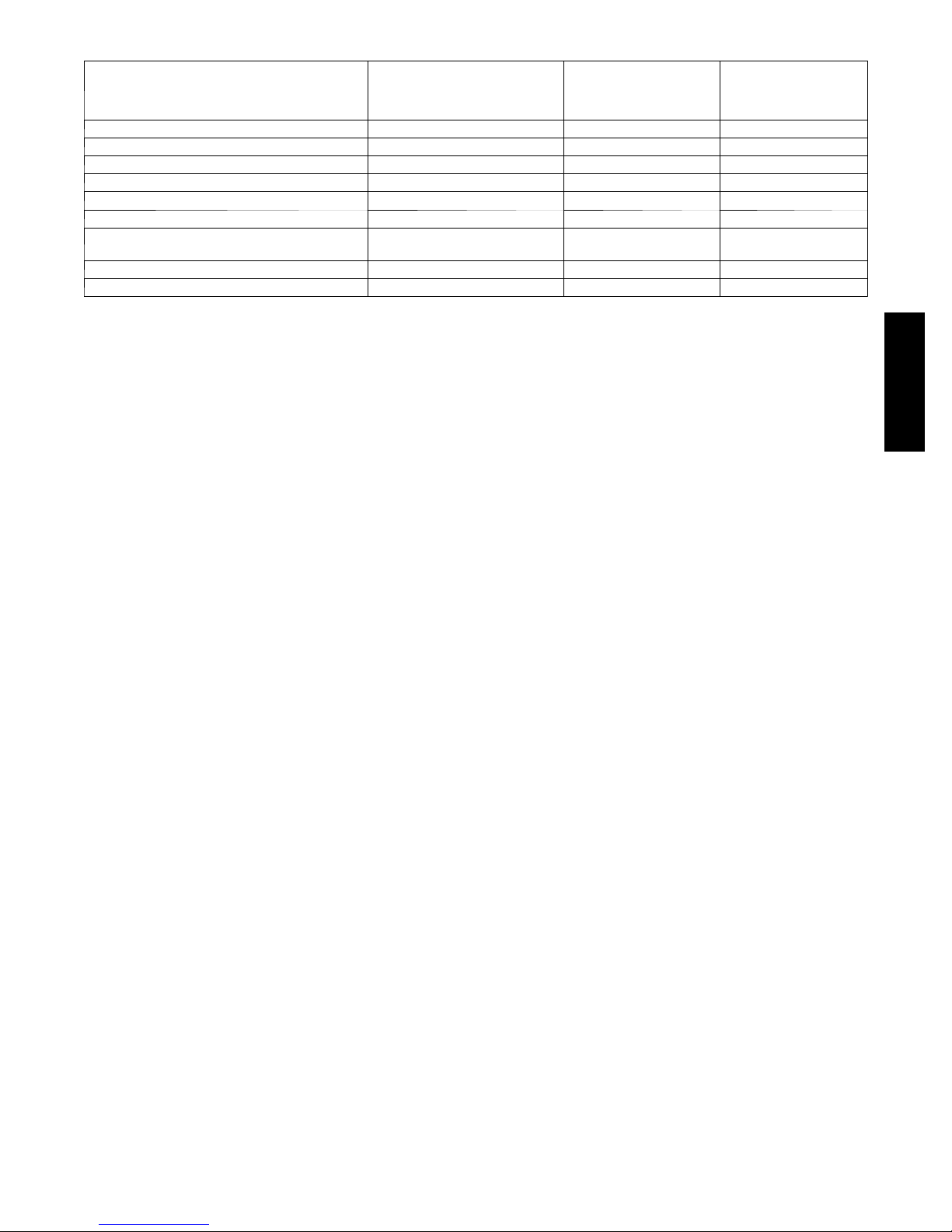
PHYSICAL DATA
UNIT SIZE --- SERIES 018 --- C 024---D 030 --- D 036---C 042 ---D 048 ---D 060---D
Operating Weight lb (kg)
Shipping Weight lb (kg)
169
(76.6)
197
(89.4)
Compressor Type Scroll
REFRIGERANT Puron® (R--- 410A)
Control TXV (Puron® Hard Shutoff)
Charge lb (kg)
5.4
(2.45)
COND FAN Propeller Type, Direct Drive
Air Discharge Vertical
Air Qty (CFM) 2235 3223 3223 3800 3800 4046 4050
Motor HP 1/12 1/12 1/12 1/5 1/5 1/4 1/4
Motor RPM 800 800 800 800 800 800 800
COND COIL
Face Area (Sq ft) 19.40 17.60 17.60 22.63 25.15 25.15 25.15
Fins per In. 25 25 25 25 25 25 20
Rows 1 1 1 1 1 1 2
Circuits 3 4 4 5 6 7 7
VALVECONNECT.(In.ID)
Vapor 5/8 5/8 3/4 3/4 7/8 7/8 7/8
Liquid 3/8 3/8 3/8 3/8 3/8 3/8 3/8
REFRIGERANT TUBES (In. OD)
Rated Vapor* 5/8 3/4 7/8 1 --- 1 / 8
Liquid 3/8
* Units are rated with 25 ft (7.6 m) of lineset length. See Vapor Line Sizing and Cooling Capacity Loss table when using other sizes and lengths of lineset
Note: See unit Installation Instruction for proper installation.
162
(73.5)
204
(92.5)
5.48
(2.49)
163
(73.9)
206
(93.4)
5.80
(2.63)
191
(86.6)
225
(102.1)
6.97
(3.16)
225
(102.1)
263
(119.3)
8.70
(3.95)
231
(104.8)
269
(122.0)
9.00
(4.08)
272
(123.4)
310
(140.6)
11.37
(5.16)
114A
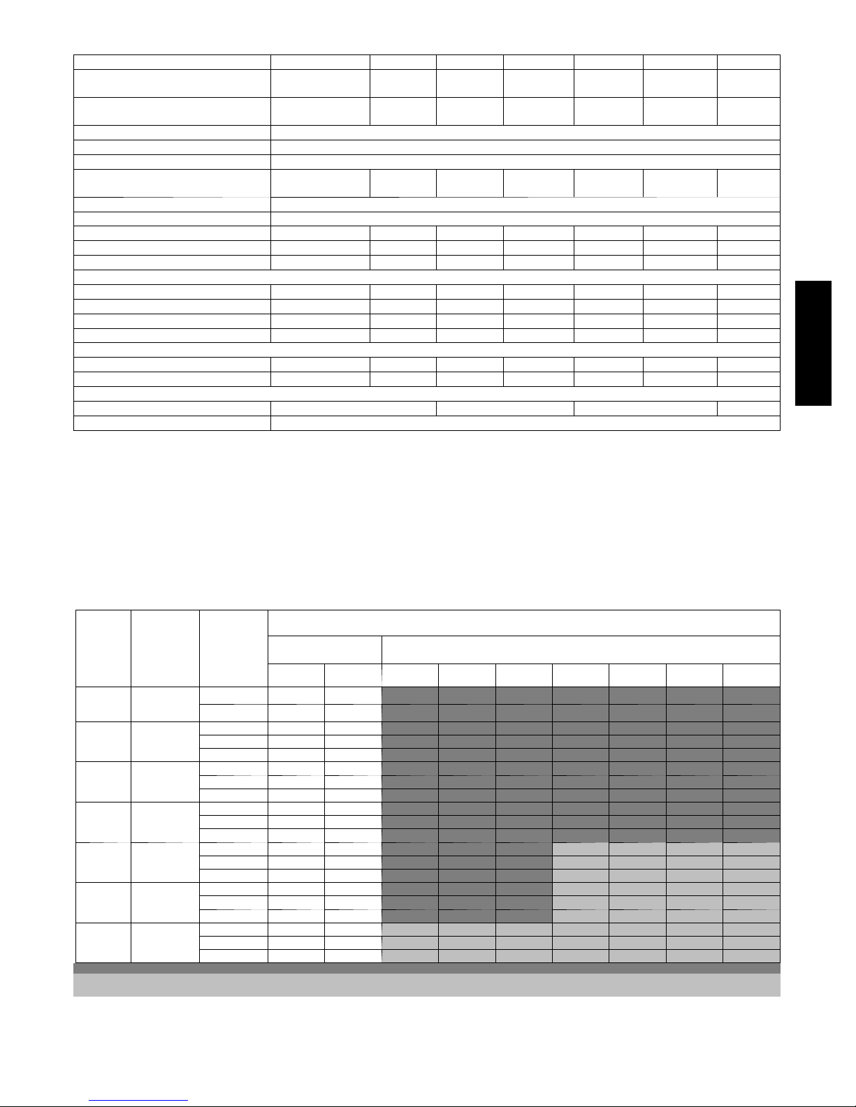
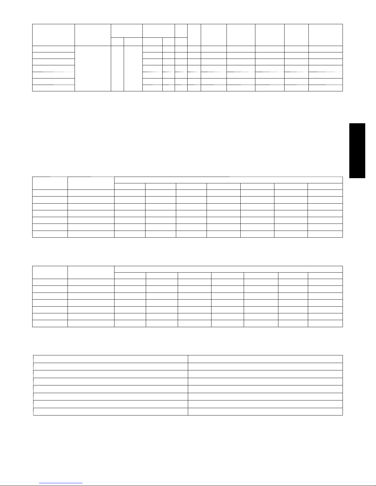
VAPOR LINE SIZING AND COOLING CAPACITY LOSS
LONG LINE APPLICATION: An application is considered ”Long
line” when the total equivalent tubing length exceeds 80 ft. (24.38
m) or when there is more than 20 ft. (6.09 m) vertical separation
between indoor and outdoor units. These applications require
additional accessories and system modifications for reliable system
operation. The maximum allowable total equivalent length is 250
ft. (76.2 m). The maximum vertical separation is 200 ft. (60.96 m)
Unit Nomi-
nal Size
(Btuh)
18000
1Stage
Puron AC
24000
1Stage
Puron AC
30000
1Stage
Puron AC
36000
1Stage
Puron AC
42000
1Stage
Puron AC
48000
1Stage
Puron AC
60000
1Stage
Puron AC
Applications in this area are long line. Accessories are required as shown recommended on Long Line Application Guidelines
Applications in this area may have height restrictions that limit allowable total equivalent length, when outdoor unit is below indoor unit See Long Line Application Guidelines
Maximum
Liquid Line
Diameters
(In. OD)
3/8
3/8
3/8
3/8
3/8
3/8
3/8
Vapo r Li ne
Diameters
(In. OD)
1/2 1 2 3 4 6 7 8 9 10
5/8 0 0 1 1 1 2 2 3 3
5/8 0 1 1 2 3 3 4 4 5
3/4 0 0 0 0 1 1 1 1 1
7/8 0 0 0 0 0 0 0 0 0
5/8 1 2 3 3 4 5 6 7 8
3/4 0 0 1 1 1 2 2 2 3
7/8 0 0 0 0 1 1 1 1 1
5/8 1 2 4 5 6 7 9 10 11
3/4 0 0 1 1 2 2 3 3 4
7/8 0 0 0 0 1 1 1 1 2
3/4 0 1 2 2 3 4 4 5 6
7/8 0 0 1 1 1 2 2 2 3
11/8 0 0 0 0 0 0 0 0 0
3/4 0 1 2 3 4 5 5 6 7
7/8 0 0 1 1 2 2 2 3 3
11/8 0 0 0 0 0 0 0 1 1
3/4 1 2 4 5 6 7 9 10 11
7/8 0 1 2 2 3 4 4 5 5
11/8 0 0 0 1 1 1 1 1 1
Standard
Application
26--- 50
(7.9---15.2)
51--- 80
(15.5---24.4)
81--- 100
(24.7---30.5)
when outdoor unit is above indoor unit, and 80 ft. (24.38 m) when
the outdoor unit is below the indoor unit. Refer to Accessory
Usage Guideline below for required accessories. See Longline
Application Guideline for required piping and system
modifications. Also, refer to the table below for the vapor tube
diameters based on the total length to minimize the cooling
capacity loss.
Cooling Capacity Loss (%)
Total Equivalent Line Length ft. (m)
Long Line Application Requires Accessories
101--- 125
(30.8---38.1)
126--- 150
(38.4---45.7)
151--- 175
(46.0---53.3)
176--- 200
(53.6---61.0)
201--- 225
(61.3---68.6)
226--- 250
(68.9---76.2)
3
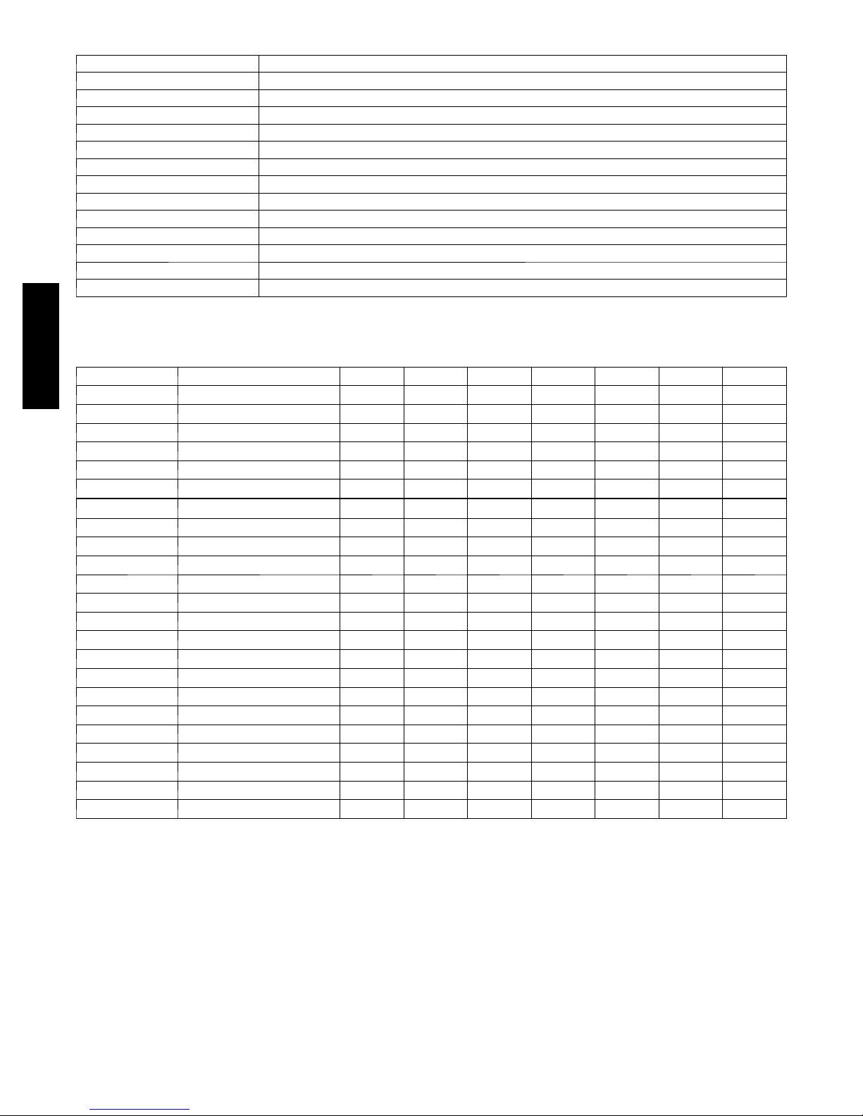
ACCESSORY THERMOSTATS
THERMOSTAT / SUBBASE PKG. DESCRIPTION
T 6 --- P R H --- 0 1 Programmable Thermidistat
T 6 --- N R H --- 0 1 Non ---programmable Thermidistat
T 1 --- PA C --- 0 1 Legacy RNC Series Programmable AC Stat
T 1 --- N A C --- 0 1 Legacy RNC Series Non --- programmable AC Stat
TSTATBBPRH01 --- B Thermidistat Control --- Programmable / Non ---Programmable Thermostat with Humidity control
TSTATBBPAC01 --- B T he rm o st a t --- A u t o C h an ge o v e r, 7 --- D a y P r o g r am m ab le , _F/_C , 1 --- S t ag e H e at , 1 --- S ta g e C oo l
TSTATBBNAC01--- C T h e rm o st a t --- A u t o C h a n g e ov e r , N o n --- P r o gr a m m ab l e , _F/_C , 1 --- S ta g e H e a t , 1 --- S t ag e C o ol
TSTATBBBAC01 --- B Builder’s Thermostat --- Manual Changeover, Non--- Programmable, _F/_C , 1 --- S t a ge H e a t, 1 --- S ta g e C oo l
TSTATBBSEN01---B Outdoor Air Temperature Sensor
TSTATXXBBP01 Backplate for Builder’s Thermostat
TSTATXXNBP01 Backplate for Non --- Programmable Thermostat
TSTATXXPBP01 Backplate for Programmable Thermostat
TSTATXXCNV10 Thermostat Conversion Kit (4 to 5 wires) -- - 10 Pack
ACCESSORIES
114A
KIT NUMBER DESCRIPTION 018 --- C 024--- D 030--- D 036--- C 042---D 048 --- D 060 --- D
HC32GE229 MOTOR FAN BALL BEARING X X X
HC38GE228 MOTOR FAN BALL BEARING X X
HC40GE228 MOTOR FAN BALL BEARING X X
KAACH1401AAA CRANKCASE HTR X X X X
KAACH1201AAA CRANKCASE HTR X X X
KAACS0201PTC START ASSIST PTC X X X X X X X
KAAFT0101AAA FREEZE THERMOSTAT X X X X X X X
KAAHI0501PUR HIGH PRESSURE SWITCH X X X X X X X
KAALP0401PUR LOW PRESSURE SWITCH X X X X X X X
KAALS0201LLS SOL VALVE X X X X X X X
KAATD0101TDR TIME DELAY RELAY X X X X X X X
KAAWS0101AAA WINTER START X X X X X X X
KSACY0101AAA CYCLE PROTECTOR X X X X X X X
KSAHS1701AAA HARD START (CAP / RELAY) X X X X X X X
KSALA0301410 LOW AMBIENT PSW X X X X X X X
KSALA0601AAA MOTORMASTER 230V X X X X X X X
KSASF0101AAA SUPPORT FEET X X X X X X X
KSASH0601COP SOUND HOOD X X X X X X
KSASH2101COP SOUND HOOD X
KSATX0201PUR TXV PURON HSO X X X
KSATX0301PUR TXV PURON HSO X X
KSATX0401PUR TXV PURON HSO X
KSATX0501PUR TXV PURON HSO X
x = Accessory
4
ACCESSORY USAGE GUIDELINE
REQUIRED FOR LOW--- AMBI-
ACCESSORY
Ball Bearing Fan Motor Yes{ No No
Compressor Start Assist Capacitor and Relay Yes Yes No
Crankcase Heater Yes Yes No
Evaporator Freeze Thermostat Yes No No
H a r d S h u t --- O ff T X V Yes Ye s Yes
Liquid Line Solenoid Valve No No No
Motor Master®Control or
Low--- ambient Pressure Switch
Support Feet Recommended No Recommended
* For tubing line sets between 80 and 200 f t. (24.38 and 60.96 m) and/or 20 ft. (6.09 m) vertical differential, refer to Residential Split---System Longline
Application Guideline.
{ Required for Low ---Ambient Controller (full modulation feature) MotorMasterr Control.
Winter Start Control Yes No No
ENT COOLING APPLICATIONS
(Below 55°F/12.8_C)
Yes No No
REQUIRED FOR LONG
LINE
APPLICATIONS*
(Over 80 ft./24.38 m)
Accessory Description and Usage (Listed Alphabetically)
1. Ball--Bearing Fan Motor
A fan motor with ball bearings which permits speed reduction
while maintaining bearing lubrication.
Usage Guideline:
Required on all units when MotorMasterr is used.
2. Compressor Start Assist -- Capacitor and Relay
Start capacitor and relay gives a ”hard” boost to compressor motor
at each start up.
Usage Guideline:
Required for reciprocating compressors in the
following applications:
Long line
Low ambient cooling
Hard shut off expansion valve on indoor coil
Liquid line solenoid on indoor coil
Required for single--phase scroll compressors in the
following applications:
Long line
Low ambient cooling
Suggested for all compressors in areas with a history of
low voltage problems.
3. Compressor Start Assist — PTC Type
Solid state electrical device which gives a ”soft” boost to the
compressor at each start--up.
Usage Guideline:
Suggested in installations with marginal power supply.
4. Crankcase Heater
An electric resistance heater which mounts to the base of the
compressor to keep the lubricant warm during off cycles. Improves
compressor lubrication on restart and minimizes the chance of
liquid slugging.
Usage Guideline:
Required in low ambient cooling applications.
Required in long line applications.
Suggested in all commercial applications.
5. Cycle Protector
The cycle protector is designed to prevent compressor short
cycling. This control provides an approximate 5 --minute delay after
power to the compressor has been interrupted for any reason,
including power outage, protector control trip, thermostat jiggling,
or normal cycling.
6. Evaporator Freeze Thermostat
An SPST temperature--actuated switch that stops unit operation
when evaporator reaches freeze--up conditions.
Usage Guideline:
Required when low ambient kit has been added.
7. Low--Ambient Pressure Switch Kit
A long life pressure switch which is mounted to outdoor unit
service valve. It is designed to cycle the outdoor fan motor in order
to maintain head pressure within normal operating limits
(approximately 100 psig to 225 psig). The control will maintain
working head pressure at low--ambient temperatures down to 0_F
(--18_C) when properly installed.
Usage Guideline:
A Low--Ambient Pressure Switch or MotorMasterr
Low-- Ambient Controller must be used when cooling operation is
used at outdoor temperatures below 55_F (12.8_C).
8. MotorMasterr Low--Ambient Controller
A fan-- speed control device activated by a temperature sensor,
designed to control condenser fan motor speed in response to the
saturated, condensing temperature during operation in cooling
mode only. For outdoor temperatures down to --20_F (--28.9_C), it
maintains condensing temperature at 100_F ±10_F (37.8_C ±
5.5_C).
Usage Guideline:
A MotorMasterr Low Ambient Controller or
Low-- Ambient Pressure Switch must be used when
cooling operation is used at outdoor temperatures
below 55_F (12.8_C).
Suggested for all commercial applications.
9. Outdoor Air Temperature Sensor
Designed for use with Bryant Thermostats listed in this
publ
i
cation. This device enables the thermostat to display the
outdoor temperature. This device also
is required to enable special thermostat features such as auxiliary
heat lock out.
Usage Guideline:
Suggested for all Bryant thermostats listed in this
publication.
REQUIRED FOR
SEA COAST
APPLICATIONS
(Within2miles/3.22km)
114A
5

Accessory Description and Usage (Listed Alphabetically) (Continued)
10. Sound Hood
Wraparound sound reducing cover for the compressor. Reduces the
sound level by about 2 dBA.
Usage Guideline:
Suggested when unit is installed closer than 15 ft (4.57 m) to
quiet areas, bedrooms, etc.
Suggested when unit is installed between two houses less
than 10 ft (3.05 m) apart.
11. Support Feet
Four stick --on plastic feet that raise the unit 4 in. (101.6 mm) above
the mounting pad. This allows sand, dirt, and other debris to be
flushed from the unit base, minimizing corrosion.
Usage Guideline:
Suggested in the following applications:
Coastal installations.
Windy areas or where debris is normally circulating.
Rooftop installations.
For improved sound ratings.
114A
12. Thermostatic Expansion Valve (TXV)
A modulating flow--control valve which meters refrigerant liquid
flow rate into the evaporator in response to the superheat of the
refrigerant gas leaving the evaporator.
Kit includes valve, adapter tubes, and external equalizer tube. Hard
shut off types are available.
NOTE: When using a hard shut off TXV with single phase
reciprocating compressors, a Compressor Start Assist Capacitor
and Relay is required.
Usage Guideline:
Required to achieve ARI ratings in certain equipment
combinations. Refer to combination ratings.
Hard shut off TXV or LLS required in air conditioner
long line applications.
Required for use on all zoning systems.
13. Time--Delay Relay
An SPST delay relay which briefly continues operation of indoor
blower motor to provide additional cooling after the compressor
cycles off.
NOTE: Most indoor unit controls include this feature. For those
that do not, use the guideline below.
14. Winter Start Control
This control is designed to alleviate nuisance opening of the
low--pressure switch by bypassing it for the first 3 minutes of
operation.
Usage Guideline:
For improved efficiency ratings for certain
combinations of indoor and outdoor units. Refer to
ARI Unitary Directory.
6
ELECTRICAL DATA
OPER
UNIT SIZE V/PH
018 -- C
024 -- D 58.3 13.5 0.5 17.3 14 14 46 (14.0) 43 (13.1) 30
030 -- D 73.0 14.1 0.5 18.1 14 14 44 (13.4) 41 (12.5) 30
036 -- C 79.0 16.7 1.2 22.0 12 12 57 (17.4) 54 (16.5) 35
042 -- D 112.0 17.9 1.2 23.6 10 10 85 (26.0) 80 (24.4) 40
048 -- D 117.0 21.8 1.2 28.4 10 10 70 (21.3) 67 (20.4) 40
060 -- D 134.0 26.4 1.2 34.2 8 8 91 (27.7) 86 (26.2) 50
* Permissible limits of the voltage r ange at which the unit will operate satisfactorily
{ If wire is applied at ambient greater than 30° C (86° F), consult table 310---16 of the NEC (ANSI/NFPA 70). The ampacity of non ---metallic ---sheathed cable
(NM), trade name ROMEX, shall be that of 60° C conditions, per the NEC (ANSI/NFPA 70) Article 336---26. If other than uncoated (no---plated), 60 or 75° C
insulation, copper wire (solid wire for 10 AWG or smaller, stranded wire for larger than 10 AWG) is used, consult applicable tables of the NEC (ANSI/NFPA 70).
} Length shown is as measured 1 way along wire path between unit and service panel for voltage drop not to exceed 2%.
* * T i me --- De la y f use .
FLA --- F u l l L oa d A m ps
LRA --- L oc ke d R o t or A m ps
MCA --- Minimum Circuit Amps
RLA ---RatedLoadAmps
NOTE: Control circuit is 24---V on all units and requires external power source. Copper wire must be used from service disconnect to unit.
All motors/compressors contain internal overload protection.
208/230/1---60 253 197
VOLTS*
MAX MIN LRA RLA FLA
COMPR FAN
48.0 9.0 0.5 11.7 14 14 67 (20.4) 64 (19.5) 15
MCA
MIN WIRE
SIZE{
60° C
MIN WIRE
SIZE{
75° C
MAX
LENGTH
ft (m)}
60° C
MAX
LENGTH
ft (m)}
75° C
MAX FUSE**
or CKT BRK
AMPS
A--WEIGHTED SOUND POWER LEVEL (dBA)
UNIT SIZE --
SERIES
018 -- C 76 56.0 60.0 65.0 72.0 65.0 60.5 53.5
024 -- D 76 50.5 61.5 68.0 67.5 64.0 60.0 53.5
030 -- D 76 52.0 62.5 71.0 69.0 65.0 62.0 59.5
036 -- C 76 52.0 60.0 65.5 69.5 64.0 63.0 56.0
042 -- D 77 55.0 62.0 66.0 70.5 65.5 60.0 54.0
048 -- D 78 51.5 62.0 67.5 73.5 69.0 64.5 62.0
060 -- D 78 57.0 62.5 69.0 73.0 66.0 62.0 57.5
NOTE: Tested in accordance with ARI Standard 270 ---95 (not listed in ARI).
STANDARD RATING
(dBA)
125 250 500 1000 2000 4000 8000
TYPICAL OCTAVE BAND SPECTRUM (dBA, without tone adjustment)
114A
A--WEIGHTED SOUND POWER LEVEL (dBA) WITH ACCESSORY SOUND HOOD
UNIT SIZE --
SERIES
018 -- C 74 56.0 60.0 65.0 69.0 63.0 60.0 52.5
024 -- D 74 51.5 61.0 67.5 66.5 63.0 59.0 51.5
030 -- D 74 53.0 62.0 68.5 68.0 64.5 61.0 56.0
036 -- C 75 52.0 62.0 65.5 67.5 63.0 61.0 53.5
042 -- D 74 55.0 61.5 65.0 68.5 65.0 59.0 52.0
048 -- D 76 53.0 61.5 67.5 72.0 68.0 61.5 59.0
060 -- D 75 57.0 62.5 68.5 71.0 65.0 60.5 58.5
NOTE: Tested in accordance with ARI Standard 270 ---95 (not listed in ARI).
STANDARD RATING
(dBA)
125 250 500 1000 2000 4000 8000
TYPICAL OCTAVE BAND SPECTRUM (dBA, without tone adjustment)
CHARGING SUBCOOLING (TXV--TYPE EXPANSION DEVICE)
UNIT SIZE --- SERIES REQUIRED SUBCOOLING _F(_C)
018 --- C 10 (5.6)
024 --- D 10 (5.6)
030 --- D 11 (6.1)
036 --- C 10 (5.6)
042 --- D 8 (4.4)
048 --- D 8 (4.4)
060 --- D 9 (5.0)
7
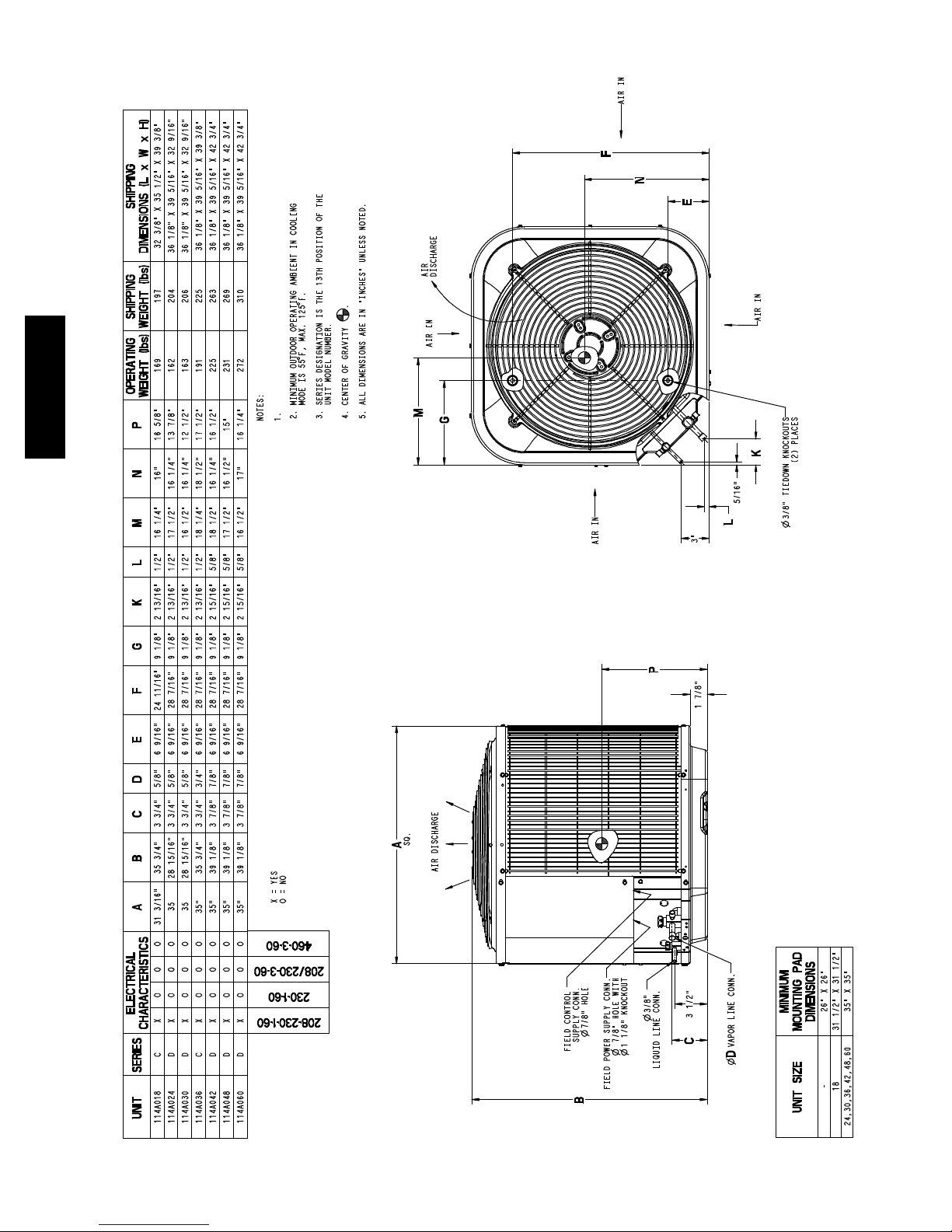
114A
Allow 24” betw een units or 18” if no overh ang within 12 ft.
DIMENSIONS -- ENGLISH
8
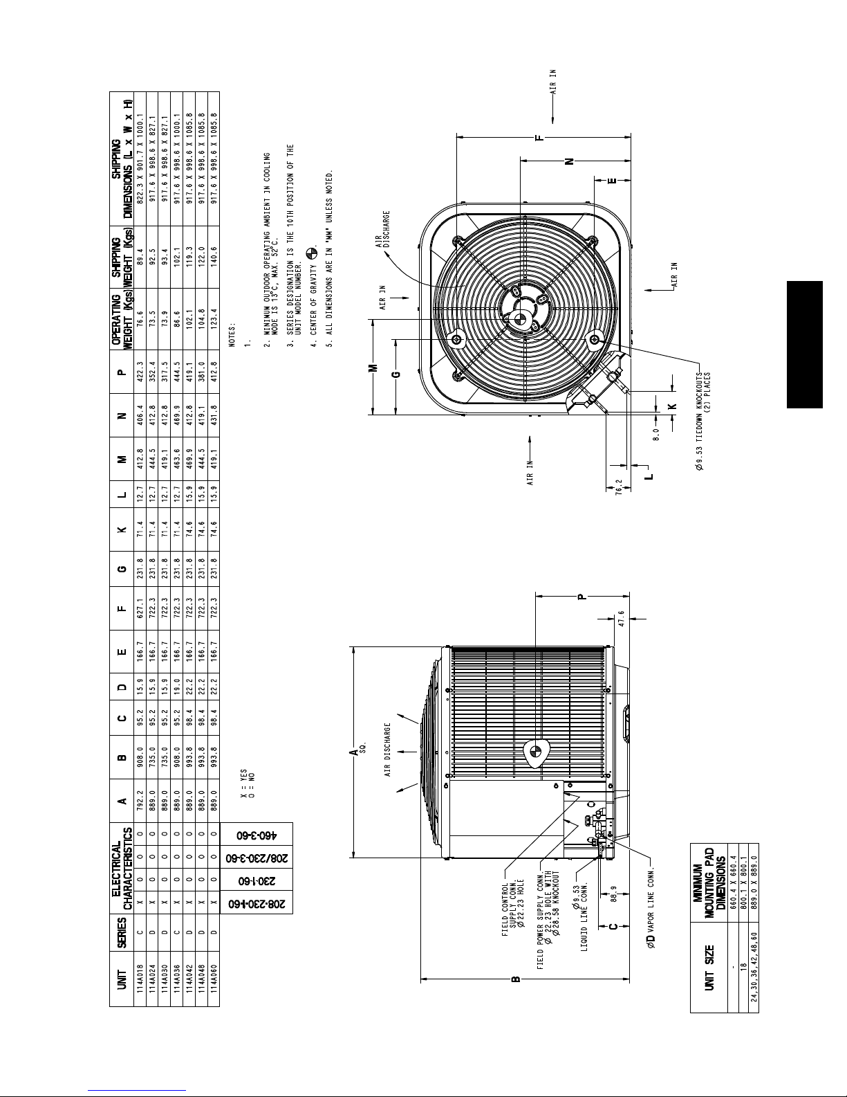
Allow 609.6 mm between units or 457.2 mm ifno overhang
within 3 .7 m.
114A
DIMENSIONS -- SI
9
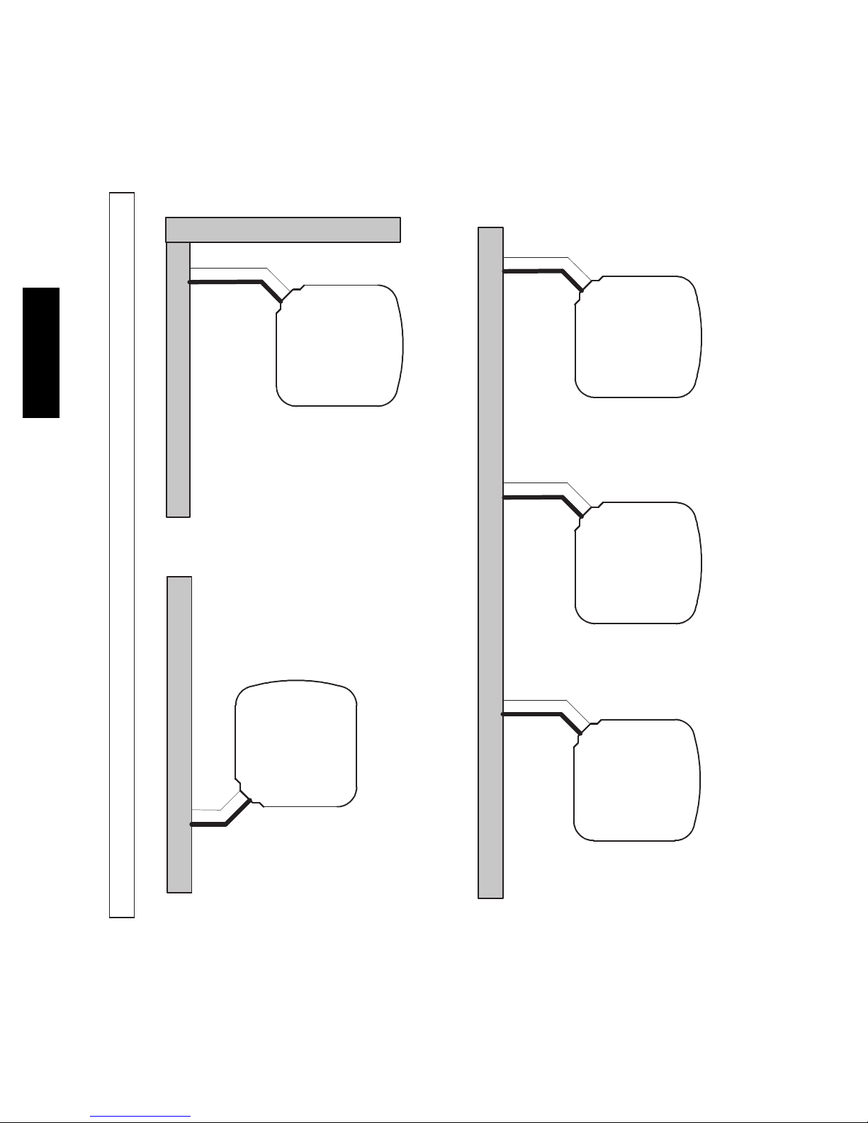
Wall
6”
(152.4)
114A
24”
Wall
(609.6)
CLEARANCES
Clearances (various examples)
6”
Wall
(152.4)
Service
12”
(304.8)
12”
(304.8)
12”
(304.8)
12”
(304.8)
Wall
24”
(609.6)
24”
(609.6)
Service
18”
(457.2)
Service
18”
(457.2)
24”
(609.6)
Service
10
24”
(609.6)
Service
18”
(457.2)
Note: Numbers in ( ) = mm
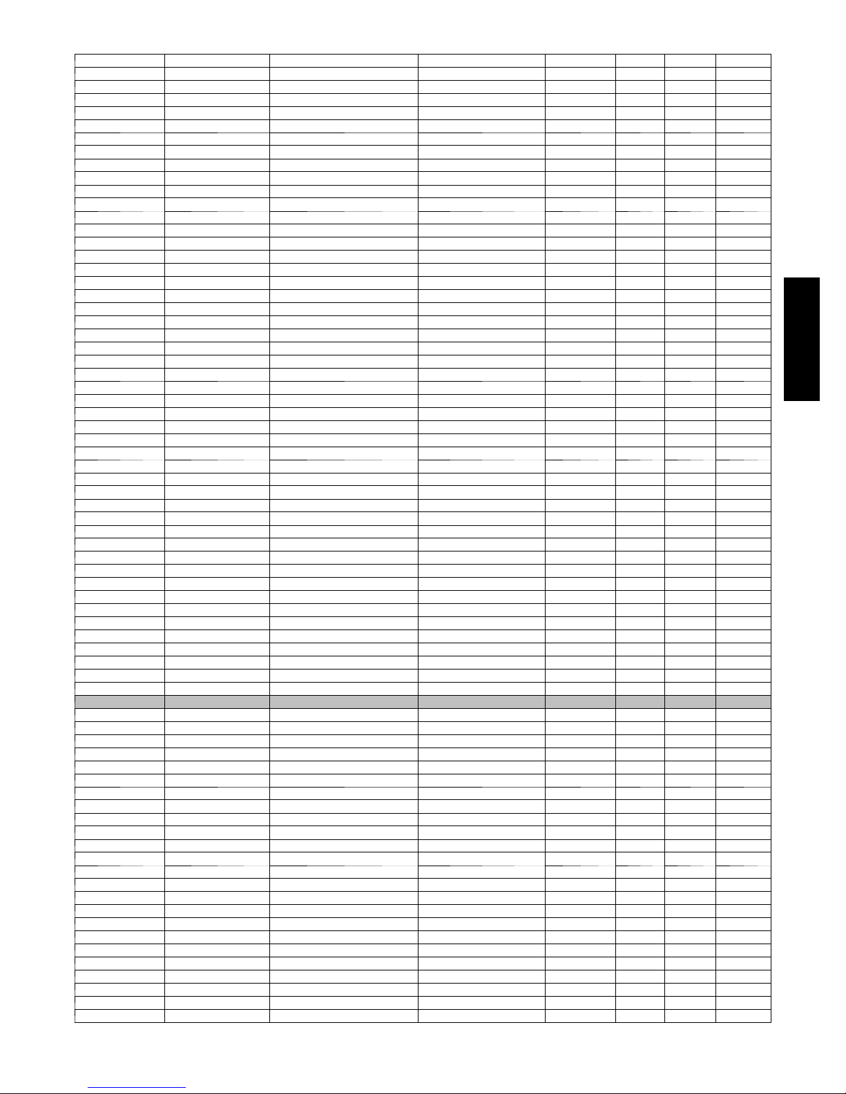
COMBINATION RATINGS
ARI Ref. No. Model Number Indoor Model Furnace Mo de l Capacity EER SEER Phase
3042449 114ANA018---C {CAP**2414A**+TDR 18000 11.50 14.00 1
3042483 114ANA018---C CAP**1814A** 313*AV024045 17900 12.50 15.00 1
3042451 114ANA018---C CAP**1814A** 315(A,J)AV036070 17600 12.50 15.00 1
3042450 114ANA018---C CAP**1814A**+T DR 17800 11.20 13.50 1
3042484 114ANA018---C CAP**2414A** 313*AV024045 18000 13.00 15.50 1
3042452 114ANA018---C CAP**2414A** 315(A,J)AV036070 17900 13.00 15.00 1
3042455 114ANA018---C CAP**2417A** 315(A,J)AV048090 17900 13.00 15.00 1
3099797 114ANA018---C CAP**2417A** 353AAV036040 18000 13.00 15.50 1
3099798 114ANA018---C CAP**2417A** 353AAV036060 18000 13.00 15.50 1
3042454 114ANA018---C CAP**2417A** 355(A,C)AV042060 17900 13.00 15.00 1
3042453 114ANA018---C CAP**2417A**+T DR 18000 11.50 14.00 1
3042469 114ANA018---C CNPF*2418A**+TDR 18000 11.50 14.00 1
3042487 114ANA018---C CNPH*2417A** 313*AV024045 18000 13.00 15.50 1
3042467 114ANA018---C CNPH*2417A** 315(A,J)AV036070 17900 13.00 15.00 1
3042468 114ANA018---C CNPH*2417A** 315(A,J)AV048090 17900 13.00 15.00 1
3099801 114ANA018---C CNPH*2417A** 353AAV036040 18000 13.00 15.50 1
3099802 114ANA018---C CNPH*2417A** 353AAV036060 18000 13.00 15.50 1
3042464 114ANA018---C CNPH*2417A** 355(A ,C)AV042040 17900 13.00 15.00 1
3042465 114ANA018---C CNPH*2417A** 355(A ,C)AV042060 17900 13.00 15.00 1
3042466 114ANA018---C CNPH*2417A** 355(A ,C)AV042080 17900 13.00 15.00 1
3042463 114ANA018---C CNPH*2417A**+TDR 18000 11.50 14.00 1
3042485 114ANA018---C CNPV*1814A** 313*AV024045 17900 12.50 15.00 1
3042457 114ANA018---C CNPV*1814A** 315(A,J)AV036070 17600 12.50 15.00 1
3042456 114ANA018---C CNPV*1814A**+TDR 17800 11.20 13.50 1
3042486 114ANA018---C CNPV*2414A** 313*AV024045 18000 13.00 15.50 1
3042459 114ANA018---C CNPV*2414A** 315(A,J)AV036070 17900 13.00 15.00 1
3042458 114ANA018---C CNPV*2414A**+TDR 18000 11.50 14.00 1
3042462 114ANA018---C CNPV*2417A** 315(A,J)AV048090 17900 13.00 15.00 1
3099799 114ANA018---C CNPV*2417A** 353AAV036040 18000 13.00 15.50 1
3099800 114ANA018---C CNPV*2417A** 353AAV036060 18000 13.00 15.50 1
3042461 114ANA018---C CNPV*2417A** 355(A,C) AV042060 17900 13.00 15.00 1
3042460 114ANA018---C CNPV*2417A**+TDR 18000 11.50 14.00 1
3042488 114ANA018---C CSPH*2412A** 313*AV024045 18000 13.00 15.50 1
3042474 114ANA018---C CSPH*2412A** 315(A,J)AV036070 17900 13.00 15.00 1
3042475 114ANA018---C CSPH*2412A** 315(A,J)AV048090 17900 13.00 15.00 1
3099803 114ANA018---C CSPH*2412A** 353AAV036040 18000 13.00 15.50 1
3099804 114ANA018---C CSPH*2412A** 353AAV036060 18000 13.00 15.50 1
3042471 114ANA018---C CSPH*2412A** 355(A,C)AV042040 17900 13.00 15.00 1
3042472 114ANA018---C CSPH*2412A** 355(A,C)AV042060 17900 13.00 15.00 1
3042473 114ANA018---C CSPH*2412A** 355(A,C)AV042080 17900 13.00 15.00 1
3042470 114ANA018---C C SPH*2412A**+TDR 18000 12.00 14.00 1
3042480 114ANA018---C FF1ENP018 17800 11.20 13.50 1
3042481 114ANA018---C FF1ENP024 18000 11.20 13.50 1
3042482 114ANA018---C FV4BNF002 18200 13.20 15.00 1
3042478 114ANA018---C FX4CNF018 18000 13.00 15.00 1
3042479 114ANA018---C FX4CNF024 18300 13.00 15.00 1
3042476 114ANA018---C FY4ANF018 17800 11.20 13.50 1
3042477 114ANA018---C FY4ANF024 17900 11.20 13.50 1
114A
3042489 114ANA024---D {CAP**2414A**+TDR 23200 11.70 14.00 1
3042569 114ANA024---D CAP**2414A** 313*AV024045 23200 13.00 15.50 1
3042490 114ANA024---D CAP**2414A** 315(A,J)AV036070 23000 13.00 15.00 1
3042493 114ANA024---D CAP**2417A** 315(A,J)AV048090 23000 13.00 15.00 1
3099805 114ANA024---D CAP**2417A** 353AAV036040 23200 13.00 15.50 1
3099806 114ANA024---D CAP**2417A** 353AAV036060 23200 13.00 15.50 1
3099807 114ANA024---D CAP**2417A** 353AAV036080 23200 13.00 15.50 1
3042492 114ANA024---D CAP**2417A** 355(A,C)AV042060 23000 13.00 15.00 1
3042491 114ANA024---D CAP**2417A**+TDR 23200 11.70 14.00 1
3042570 114ANA024---D CAP**3014A** 313*AV024045 23400 13.00 15.50 1
3042495 114ANA024---D CAP**3014A** 315(A,J)AV036070 23200 13.00 15.00 1
3042494 114ANA024---D CAP**3014A**+TDR 23400 12.00 14.00 1
3042498 114ANA024---D CAP**3017A** 315(A,J)AV048090 23200 13.20 15.00 1
3099808 114ANA024---D CAP**3017A** 353AAV036040 23200 13.00 15.50 1
3099809 114ANA024---D CAP**3017A** 353AAV036060 23200 13.00 15.50 1
3099810 114ANA024---D CAP**3017A** 353AAV036080 23200 13.00 15.50 1
3042497 114ANA024---D CAP**3017A** 355(A,C)AV042060 23200 13.00 15.00 1
3042496 114ANA024---D CAP**3017A**+TDR 23400 12.00 14.00 1
3042533 114ANA024---D CNPF*2418A**+TDR 23200 11.70 14.00 1
3042573 114ANA024---D CNPH*2417A** 313*AV024045 23000 12.50 15.50 1
3042516 114ANA024---D CNPH*2417A** 315(A,J) AV036070 22800 13.00 15.00 1
3042517 114ANA024---D CNPH*2417A** 315(A,J) AV048090 23000 13.00 15.00 1
3042518 114ANA024---D CNPH*2417A** 315(A,J) AV060110 23000 13.00 15.00 1
3042519 114ANA024---D CNPH*2417A** 315(A,J) AV066135 23000 13.00 15.00 1
* Tested combination
11
 Loading...