

Page 1
Model 1 13A
Legacy--RNC Series Air Conditioner wit h Pu ronr
Produc t Data
the environmentally sound refrigerant
Bryant’s Air Conditioners with Puron r refrigerant provide a
collection o f features u nm atched b y an y oth er family of
equipment. The 113A has been designe d utilizing Bryant’s Puron
refrigerant. The environmentally sound refrigerant allows you to
make a responsible decision in the protection of the earth’s ozone
layer. Bryant’s air conditioning system with Puron refrigerant
meets the Energy Starr guidelines for energy efficiency.
A05233
INDUSTRY LEADING
FEATURES / BENEFITS
Efficiency
13 SEER/11 EER
S
S
Microtube Technologyt refrigeration system
S
Indoor air quality accessories available
Sound
Sound level as low as 76 dBA
S
Comfort
System supports Thermidistatt or standard thermostat
S
controls
Reliability
S
Puronr refrigerant -- environmentally sound, won’t
deplete the ozone layer and low lifetime servce cost.
S
Front--seating service valves
S
Scroll compressor
S
Internal pressure relief valve
S
Internal thermal overload
S
Filter drier
S
Balanced refrigeration system for maximum reliability
Durability
DuraGuardt protection package:
S
Solid, Durable sheet metal construction
S
Dense wire coil guard
S
Baked--on, complete coverage, powder paint
Applications
Long--line -- up to 250 feet total equivalent length, up
S
to 200 feet condenser above evaporator, or up to 80 ft.
evaporator above condenser (See Longline Guide for
more information.)
S
Low ambient (down to --20_F) with accessory kit
Warranty
5 year limited compressor warranty
S
S
5 year limited parts warranty
Page 2
MODEL NUMBER NOMENCLATURE
12345678910111214
N N N A A/N N N N N A/N A/N N A
11 3 A N A 036 0 0 0 0
Prod-
uct
Famil y
Tier SEER Major Ser ies Voltage Variations
Cooling Capacity
Open Open Open Series
N=
113A
1=AC1=Legacy
RNC
3=13 SE ER A=Puron
the environmentally sound refrigerant
208---230 ---1
or
208/230---1
C
R
E
R
U
T
C
A
F
U
N
A
M
A
R
A=Standard
T
O
D
E
A
I
R
F
I
I
T
R
E
A
I
R
C
O
Y
R
A
T
I
N
U
E
T
Q
N
U
E
I
P
M
I
S
D
T
A
R
N
A
D
0=Not
Defined
A
S
C
O
M
P
L
N
D
Y
I
T
I
N
I
O
G
N
I
N
W
G
I
T
H
0
1
2
ISO 9001:2000
REGISTERED
As an Energy Star® Partn er , Carrier
Corporation has determined that this
product meets the ENERGY STAR®
guidelines for energy efficiency
0=Not
Defined
0=Not Defined
STANDARD FEATURES
Feature 18 24 30 36 42 48 60
Puron Refrigerant X X X X X X X
13 SEER X X X X X X X
Scroll Compressor X X X X X X X
DenseWireCoilGuard X X X X X X X
FieldInstalledFilterDrier X X X X X X X
Front Seating Service Valves X X X X X X X
Internal Pressure Relief Valve X X X X X X X
Internal Thermal Overload X X X X X X X
Long Line capability X X X X X X X
Low Ambient capability with Kit X X X X X X X
A=
Original
Series
2
Page 3
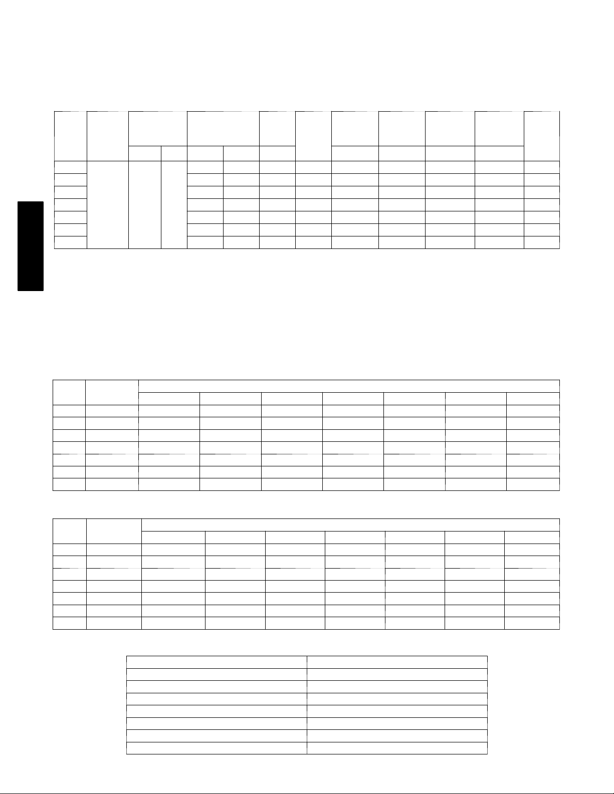
PHYSICAL DATA
UNIT SIZE SERIES 018 ---A 024---A 030---A 036---A 042 ---A 048---A 060 ---A
Operating Weight (lb) 125 125 134 152 189 210 236
Shipping Weight (lb) 146 146 155 175 218 235 270
Compressor Type Scroll
REFRIGERANT Puron® (R---410A)
Control TXV (Puron® Hard Shutoff)
Charge (lb) 4.25 4.35 4.75 5.25 6.2 8.35 8.75
COND FAN Propeller Type, Direct Drive
Air Discharge Vertical
Air Qty (CFM) 1880 2200 2200 2950 3170 3365 4050
Motor HP 1/12 1/10 1/10 1/4 1/5 1/4 1/5
Motor RPM 1100 1100 1100 1100 1100 1100 825
COND COIL
Face Area (Sq ft) 9.85 9.85 11.49 14.77 17.25 21.56 25.15
Fins per In. 20 20 25 25 25 25 25
Rows 1 1 1 1 1 1 1
Circuits 3 3 3 3 4 5 5
VALVECONNECT.(In.ID)
Vapor 5/8 5/8 3/4 3/4 7/8 7/8 7/8
Liquid 3/8” 3/8” 3/8” 3/8” 3/8” 3/8” 3/8”
REFRIGERANT TUBES* (In. OD)
Vapor (0 --- 80 Ft Tube Length) 5/8 5/8 3/4 3/4 7/8 7/8 1 --- 1 / 8
Liquid (0 ---80 Ft Tube Length) 3/8”
* For tubing sets between 80 and 200 ft. horizontal or 20 ft. vertical differential, consult the Longline Guideline.
Note: See unit Installation Instruction for proper installati on.
113A
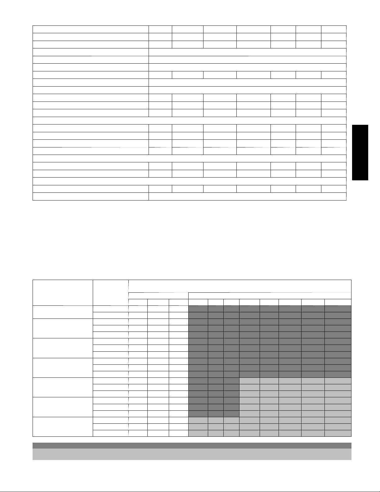
VAPOR LINE SIZING AND COOLING CAPACITY LOSS
PURON 1--STAGE AIR CONDITIONER APPLICATIONS
LONG LINE APPLICATION: An application is considered
”Long line” when the total equivalent tubing length exceeds 80 ft
or when there is more than 20 Ft vertical separation between
indoor and outdoor units. These applications require additional
accessories and system modifications for reliable system
operation. The maximum allowable total equivalent length is
250Ft. The maximum vertical separation is 200 Ft when outdoor
Acceptable
Unit Nominal Size
(Btuh)
18000
1StagePuronAC
24000
1StagePuronAC
30000
1StagePuronAC
36000
1StagePuronAC
42000
1StagePuronAC
48000
1StagePuronAC
60000
1StagePuronAC
Vapor Line
Diameters
(In. OD)
1/2 1 2 3 3 4 6 7 8 9 10 12
5/8 0 0 1 1 1 1 2 2 3 3 3
5/8 0 1 1 1 2 3 3 4 4 5 6
3/4 0 0 0 0 0 1 1 1 1 1 2
7/8 0 0 0 0 0 0 0 0 0 0 1
5/8 1 2 3 3 3 4 5 6 7 8 9
3/4 0 0 1 1 1 1 2 2 2 3 3
7/8 0 0 0 0 0 1 1 1 1 1 1
5/8 1 2 4 4 5 6 7 9 10 11 13
3/4 0 0 1 1 1 2 2 3 3 4 4
7/8 0 0 0 0 0 1 1 1 1 2 2
3/4 0 1 2 2 2 3 4 4 5 6 6
7/8 0 0 1 1 1 1 2 2 2 3 3
11/8 0 0 0 0 0 0 0 0 0 0 1
3/4 0 1 2 2 3 4 5 5 6 7 8
7/8 0 0 1 1 1 2 2 2 3 3 4
11/8 0 0 0 0 0 0 0 0 1 1 1
3/4 1 2 4 4 5 6 7 9 10 11 12
7/8 0 1 2 2 2 3 4 4 5 5 6
11/8 0 0 0 0 1 1 1 1 1 1 2
Standard Application Long Line Application Requires Accessories
25 50 80 80+ 100 125 150 175 200 225 250
Standard Length = 80 Ft or less total equivalvent length
Applications in this area are long line. Accessories are required as shown recommended on Long Line Application Guidelines
Applications in this area may have height restrictions that limit allowable total equivalent length, when outdoor unit is below indoor unit See
Long Line Application Guidelines
unit is above indoor unit, and up to 80 Ft when the outdoor unit
is below the indoor unit. Refer to Accessory Usage Guideline
below for required accessories. See Long--Line Application
Guideline for required piping and system modifications. Also,
refer to the table below for the acceptable vapor tube diameters
based on the total length to minimize the cooling capacity loss.
Cooling Capacity Loss (%)
Total Equivalent Line Length (ft)
3
Page 4
ACCESSORY THERMOSTATS
THERMOSTAT / SUBBASE PKG. DESCRIPTION
TSTATBBPRH01 ---B Thermidistat Control --- Programmable / Non ---Programmable Thermostat with Humidity control
TSTATBBPAC01--- B T h e r m o s t a t --- A u t o C h a n g e o v e r, 7 --- D a y P r o g r a m m a b l e , _F/_C, 1 --- S t a g e H e a t , 1 --- S t a g e C o o l
TSTATBBNAC01 ---C T h e r m o stat --- A u t o C h a n g e o v e r, N o n --- P r o g r a m m a b l e , _F/_C , 1 --- S t a g e H e a t , 1 --- S t a g e C o o l
TSTATBBBAC01 --- B Builder’s Thermostat --- Manual Changeover, Non---Programmable, _F/_C , 1 --- S t a g e H e a t , 1 --- S t a g e C o o l
TSTATBBSEN01 ---B Outdoor Air Temperature Sensor
TSTATXXBBP01 Backplate for Builder’s Thermostat
TSTATXXNBP01 Backplate for Non ---Programmable Thermostat
TSTATXXPBP01 Backplate for Programmable Thermos tat
TSTATXXCNV10 Thermostat Conversion Kit (4 to 5 wires) --- 10 Pack
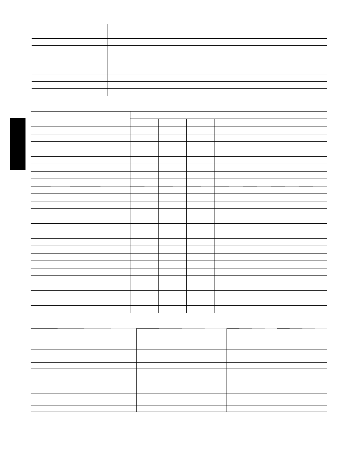
ACCESSORIES
KIT NUMBER DESCRIPTION
KAAFT0101AAA FREEZE THERMOSTAT X X X X X X X
KAATD0101TDR TIME DELAY RELAY X X X X X X X
KAAWS0101AAA WINTER START X X X X X X X
113A
KSALA0301410 LOW AMBIENT PSW X X X X X X X
KSALA0601AAA MOTORMASTER 230V X X X X X X X
HC32GE234 MOTOR FAN BALL BEARING X
HC34GE239 MOTOR FAN BALL BEARING X X
HC40GE226 MOTOR FAN BALL BEARING X X
HC38GE219 MOTOR FAN BALL BEARING X
HC40GE228 MOTOR FAN BALL BEARING X
KSAHS1701AAA HARD START (CAP / RELAY) X X X X X X X
KSACY0101AAA CYCLE PROTECTOR X X X X X X X
KSASF0101AAA SUPPORT FEET X X X X X X X
KAACS0201PTC START ASSIST PTC X X X X X X X
KAACH1201AAA CRANKCASE HTR X X X
KAACH1401AAA CRANKCASE HTR X X X X
KSATX0201PUR TXV PURON HSO X X X
KSATX0301PUR TXV PURON HSO X X
KSATX0401PUR TXV PURON HSO X
KSATX0501PUR TXV PURON HSO X
KSASH1801COP SOUND HOOD X X X X
KSASH0601COP SOUND HOOD X X
KSASH2101COP SOUND HOOD X
KAALP0301PUR LOW PRESSURE SWITCH X X X X X X X
KAAHI0401PUR HIGH PRESSURE SWITCH X X X X X X X
18---30 24- --30 30 --- 30 36 --- 30 42 ---30 48---30 60--- 30
Size --- Voltage & Series
ACCESSORY USAGE GUIDELINE
REQUIRED FOR
LONG LINE
APPLICATIONS*
(Over 80 Ft. )
ACCESSORY
REQUIRED FOR LOW--- AMBIENT
COOLING APPLICATIONS
(Below 55° F)
Crankcase Heater Ye s Yes No
Evaporator Freeze Thermostat Yes No No
Accumulator No No No
Compressor Start Assist Capacitor and Relay Yes Yes No
Motor Master®Control or Low --- ambient
Pressure Switch
Yes No No
Support Feet Recommended No Recommended
Liquid Line Solenoid Valve No
S e e L o n g --- L i n e A p -
plication Guideline
Ball Bearing Fan Motor Yes{ No No
* For tubing line sets between 80 and 200 ft. and/or 20 ft. vertical differntial, refer to Residential Split ---System Longline Application Guideline.
{ Required for Low---Ambient Controller (ful l modulation feature) and MotorMasterr Control only.
4
REQUIRED FOR
SEA COAST
APPLICATIONS
(Within 2 miles)
No
Page 5

Accessory Description and Usage (Listed Alphabetically)
1. Ball-- Bearing Fan Motor
A fan motor with ball bearings which permits speed reduction
while maintaining bearing lubrication.
Usage Guideline:
Required on all units when MotorMasterr —
2. Compressor Start Assist -- Capacitor and Relay
Start capacitor and relay gives a ”hard” boost to compressor
motor at each start up.
Usage Guideline:
Required for reciprocating compressors in the
following applications:
Long line
Low ambient cooling
Hard shut off expansion valve on indoor coil
Liquid line solenoid on indoor coil
Required for single--phase scroll compressors in the
following applications:
Long line
Low ambient cooling
Suggested for all compressors in areas with a history of
low voltage problems.
3. Compressor Start Assist — PTC Type
Solid state electrical device which gives a ”soft” boost to the
compressor at each start--up.
Usage Guideline:
Suggested in installations with marginal power supply.
4. Crankcase Heater
An electric resistance heater which mounts to the base of the
compressor to keep the lubricant warm during off cycles.
Improves compressor lubrication on restart and minimizes the
chance of liquid slugging.
Usage Guideline:
Required in low ambient cooling applications.
Required in long line applications.
Suggested in all commercial applications.
5. Cycle Protector
The cycle protector is designed to prevent compressor short
cycling. This control provides an approximate 5--minute delay
after power to the compressor has been interrupted for any
reason, including power outage, protector control trip, thermostat
jiggling, or normal cycling.
6. Evaporator Freeze Thermostat
An SPST temperature--actuated switch that stops unit operation
when evaporator reaches freeze--up conditions.
Usage Guideline:
Required when low ambient kit has been added.
7. Low--Ambient Pressure Switch Kit
A long life pressure switch which is mounted to outdoor unit
service valve. It is designed to cycle the outdoor fan motor in
order to maintain head pressure within normal operating limits
(approximately 100 psig to 225 psig). The control will maintain
working head pressure at low--ambient temperatures down to 0_F
when properly installed.
Usage Guideline:
A Low--Ambient Pressure Switch or MotorMasterr
Low--Ambient Controller must be used when cooling operation is
used at outdoor temperatures below 55_F (12.8_C).
8. MotorMasterr Low--Ambient Controller
A fan--speed control device activated by a temperature sensor,
designed to control condenser fan motor speed in response to the
saturated, condensing temperature during operation in cooling
mode only. For outdoor temperatures down to --20_F (--28.9_C),
it maintains condensing temperature at 100_F ±10_F (37.8_C ±
-- 1 2 _C).
Usage Guideline:
A MotorMasterr Low Ambient Controller or
Low--Ambient Pressure Switch must be used when
cooling operation is used at outdoor temperatures
below 55_F (12.8_C).
Suggested for all commercial applications.
9. Outdoor Air Temperature Sensor
Designed for use with Bryant Thermostats listed in this
publication. This device enables the thermostat to display the
outdoor temperature. This device also
is required to enable special thermostat features such as auxiliary
heat lock out.
Usage Guideline:
Suggested for all Bryant thermostats listed in this
publication.
10. Sound Hood
Wraparound sound reducing cover for the compressor. Reduces
the sound level by about 2 dBA.
Usage Guideline:
Suggested when unit is installed closer than 15 ft to
quiet areas, bedrooms, etc.
Suggested when unit is installed between two houses less
than 10 ft apart.
11. Support Feet
Four stick--on plastic feet that raise the unit 4 in. above the
mounting pad. This allows sand, dirt, and other debris to be
flushed from the unit base, minimizing corrosion.
Usage Guideline:
Suggested in the following applications:
Coastal installations.
Windy areas or where debris is normally circulating.
Rooftop installations.
For improved sound ratings.
12. Thermostatic Expansion Valve (TXV)
A modulating flow-- control valve which meters refrigerant liquid
flow rate into the evaporator in response to the superheat of the
refrigerant gas leaving the evaporator.
Kit includes valve, adapter tubes, and external equalizer tube.
Hard shut off types are available.
NOTE: When using a hard shut off TXV with single phase
reciprocating compressors, a Compressor Start Assist Capacitor
and Relay is required.
Usage Guideline:
Required to achieve ARI ratings in certain equipment
combinations. Refer to combination ratings.
Hard shut off TXV or LLS required in air conditioner
long line applications.
Required for use on all zoning systems.
13. Time--Delay Relay
An SPST delay relay which briefly continues operation of indoor
blower motor to provide additional cooling after the compressor
cycles off.
NOTE: Most indoor unit controls include this feature. For those
that do not, use the guideline below.
Usage Guideline:
For improved efficiency ratings for certain
combinations of indoor and outdoor units. Refer to
ARI Unitary Directory.
113A
5
Page 6
Accessory Description and Usage (Listed Alphabetically) (Continued)
14. Winter Start Control
This control is designed to alleviate nuisance opening of the
low-- pressure switch by bypassing it for the first 3 minutes of
operation.
ELECTRICAL DATA
UNIT
SIZE
18
24 58.3 13.5 0.75 17.6 14 14 45 43 25
30 64.0 12.8 0.75 16.8 14 14 47 45 25
36 77.0 14.1 1.4 19.0 12 12 66 63 30
42 112.0 17.9 1.1 23.5 12 12 53 51 40
48 109.0 19.9 1.4 26.2 10 10 76 73 40
60 134.0 26.4 1.2 34.2 8 8 91 86 50
* Permissible limits of the voltage ran ge at which the unit will operate satisfactorily
113A
{ If wire is applied at ambient greater than 30˚ C(86˚ F), consult table 310 --- 16 of the NEC (ANSI/NFPA 70). The ampacity of non --- metallic ---sheathed cable
(NM), trade name ROMEX, shall be that of 60˚ C (140˚ F) conditions, per the NEC (ANSI/NFPA 70) Article 336 ---26. If other than uncoated (no ---plated), 60
or 75˚ C (140 or 167˚ C) ins ulation, copper wire (solid wire for 10 AWG or smaller, stranded wire for larger than 10 AWG) is used, cons ult applicable tables
of the NEC (ANSI/NFPA 70).
} Length shown is as measured 1 way along wire path between unit and service panel for voltage drop not to exceed 2%.
** Time---Delay fuse.
FLA --- Ful l L o ad A mps
LRA --- L o c ke d R o tor A mps
MCA --- Minimu m Circuit Amps
RLA ---RatedLoadAmps
NOTE: Control circuit is 24 ---V on all units and requires external power source. Copper wire must be used from service disconnect to unit.
V/PH
208/230/1 253 197
All motors/compressors contain internal overload protection.
OPER
VOLTS*
MAX MIN LRA RLA FLA 60° C 75° C 60° C 75° C
COMPR FAN
MCA
48.0 9.0 0.5 11.7 14 14 67 64 15
MIN WIRE
SIZE{
MIN WIRE
SIZE{
MAX
LENGTH
(FT)}
MAX
LENGTH
(FT)}
A--WEIGHTED SOUND POWER (DBA)
UNIT
STANDARD
SIZE
18 76 52.0 61.0 67.0 70.5 67.5 63.5 56.5
24 76 56.5 64.0 67.5 69.5 67.0 65.0 60.5
30 76 55.0 63.5 69.0 72.0 69.0 64.5 59.5
36 76 58.5 64.0 68.0 69.5 66.0 62.5 55.0
42 78 57.5 65.0 71.0 73.0 70.5 67.5 62.5
48 78 59.5 67.0 72.5 73.0 70.0 67.0 62.5
60 78 53.5 61.0 67.5 74.5 68.5 62.5 61.0
RATING
125 250 500 1000 2000 4000 8000
TYPICAL OCTAVE BAND SPECTRUM (without tone adjustment)
MAX
FUSE**
or CKT
BRK
AMPS
A--WEIGHTED SOUND POWER (DBA) WITH ACCESSORY SOUND HOOD
UNIT
SIZE
STANDARD
RATING
18 74 50.0 61.5 64.5 66.5 64.0 61.0 54.5
24 75 58.0 65.5 69.0 70.5 68.0 65.0 59.0
30 76 56.5 64.0 69.5 71.5 69.0 64.5 58.0
36 76 58.5 64.5 68.5 69.5 67.0 63.5 58.5
42 77 57.5 65.0 70.5 72.0 70.0 67.0 62.0
48 77 59.5 67.0 72.0 72.0 69.5 66.5 62.0
60 77 53.0 61.0 66.5 73.0 66.0 60.5 57.5
125 250 500 1000 2000 4000 8000
TYPICAL OCTAVE BAND SPECTRUM (without tone adjustment)
CHARGING SUBCOOLING (TXV--TYPE EXPANSION DEVICE)
UNIT SIZE --- VOLTAGE & SERIES REQUIRED SUBCOOLING (_F)
018---A 8
024---A 13
030---A 16
036---A 16
042---A 10
048---A 17
060---A 11
6
Page 7
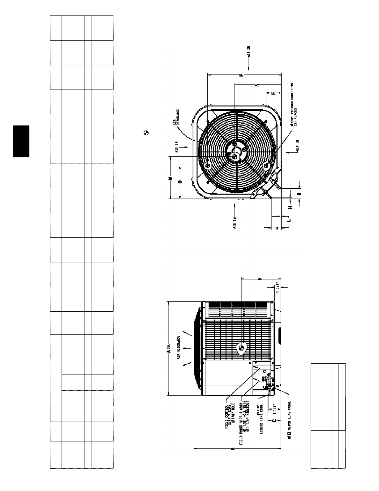
113A
1. Allow 30” clearance to service side of unit, 48” above unit, 6” on one side, 12”
on remaining side, and 24” between units for proper airflow.
2. Minimum outdoor operating ambient in cooling mode is 55 _F, max. 125_ F.
3. Se ries designation is the 13th positio n of the unit model numbe r.
(Professional Engineer), if required.
4. Center of gravity
5. For hurricane tie downs, contact distributor for detai ls and PE Certificatio n
A B C D E F G H J K L M N P
ELECTRI CAL
CHARACTERISTICS
UNIT SERIES
DIMENSIONS
X=YES
0=NO
4 60 --- 3 --- 6 0
208/230---3 --- 60
2 30 --- 1 --- 6 0
2 08 --- 2 3 0 --- 1 --- 6 0
113ANA0318 A X 0 0 0 25 3/4” 25 1/8” 33/4” 5/8” 4 7/16” 21 1/4” 91/8” 5/ 16” 3” 2 13/16” 1/2” 12 1/2” 12 3/8” 12 3/8”
113ANA0324 A X 0 0 0 25 3/4” 25 1/8” 33/4” 5/8” 4 7/16” 21 1/4” 91/8” 5/ 16” 3” 2 13/16” 1/2” 13” 11 7/8” 12 3/8”
113ANA0330 A X 0 0 0 25 3/4” 28 1/2” 33/4” 3/4” 4 7/16” 21 1/4” 91/8” 5/ 16” 3” 2 13/16” 1/2” 12 1/4” 13 3/4” 12 3/4”
113ANA0336 A X 0 0 0 25 3/4” 35 5/16” 33/4” 3/4” 4 7/16” 21 1/4” 91/8” 5/16” 3” 2 13/16” 1/2” 12” 13” 14 3/4”
113ANA0342 A X 0 0 0 31 3/16” 32 7/16” 37/8” 7/8” 6 9/16” 24 11/16” 91/8” 5/16” 3” 2 15/16” 5/8” 16 1/4” 16 1/4” 13 3/4”
113ANA0348 A X 0 0 0 31 3/16” 39 1/4” 37/8” 7/8” 6 9/16” 24 11/16” 91/8” 5/16” 3” 2 15/16” 5/8” 17 1/4” 17 1/4” 19 3/4”
113ANA0360 A X 0 0 0 35” 39 1/4” 37/8” 7/8” 6 9/16” 28 7/16” 91/8” 5/16” 3” 2 15/16” 5/8” 19 3/4” 19 3/4” 18 3/8”
PAD DIME NSIONS
MINIMUM MOUNTING
60 35” X 35”
42, 48 31 1/2” X 31 1/2”
UNIT SIZE
18, 24, 30, 36 26” X 26”
7
Page 8

COMBINATION RATINGS
Unit Size ---
Voltage &
Series
113A
018--- A
Indoor
Model
*CAP**1814A** 17,500 TXV 13.00 11.00
CAP**1814A** 17,200 TDR&TXV 14.00 11.70 315(A,J)AV036070
CAP**2414A** 17,700 TXV 13.00 11.00
CAP**2414A** 17,500 TDR&TXV 14.00 11.70 315(A,J)AV036070
CAP**2417A** 17,700 TXV 13.00 11.00
CAP**2417A** 17,500 TDR&TXV 14.00 11.70 355AAV042060
CAP**2417A** 17,600 TDR&TXV 14.00 11.70 315(A,J)AV048090
CNPV*1814A** 17,500 TXV 13.00 11.00
CNPV*1814A** 17,200 TDR&TXV 14.00 11.70 315(A,J)AV036070
CNPV*2414A** 17,700 TXV 13.00 11.00
CNPV*2414A** 17,500 TDR&TXV 14.00 11.70 315(A,J)AV036070
CNPV*2417A** 17,700 TXV 13.00 11.00
CNPV*2417A** 17,500 TDR&TXV 14.00 11.70 355AAV042060
CNPV*2417A** 17,600 TDR&TXV 14.00 11.70 315(A,J)AV048090
CNPH*2417A** 17,700 TXV 13.00 11.00
CNPH*2417A** 17,500 TDR&TXV 14.00 11.70 355AAV042040
CNPH*2417A** 17,500 TDR&TXV 14.00 11.70 355AAV042060
CNPH*2417A** 17,600 TDR&TXV 14.00 11.70 355AAV042080
CNPH*2417A** 17,500 TDR&TXV 14.00 11.70 315(A,J)AV036070
CNPH*2417A** 17,600 TDR&TXV 14.00 11.70 315(A,J)AV048090
To ta l C ap.
BTUH
Factory
Supplied
Enhancement
SEER
Standard
Rating
TDR{
EER
Furnace
Model
See notes on pg. 14
CNPF*2418A** 17,700 TXV 13.00 11.00
CSPH*2412A** 17,700 TXV 13.00 11.00
CSPH*2412A** 17,500 TDR&TXV 14.00 11.70 355AAV042040
CSPH*2412A** 17,500 TDR&TXV 14.00 11.70 355AAV042060
CSPH*2412A** 17,600 TDR&TXV 14.00 11.70 355AAV042080
CSPH*2412A** 17,500 TDR&TXV 14.00 11.70 315(A,J)AV036070
CSPH*2412A** 17,600 TDR&TXV 14.00 11.70 315(A,J)AV048090
FY4ANF018 17,400 TDR&TXV 13.00 11.00
FY4ANF024 17,500 TDR&TXV 13.00 11.00
FX4CNF018 17,600 TDR&TXV 14.00 11.70
FX4CNF024 17,900 TDR&TXV 14.00 11.70
FF1ENP018 17,400 TDR&TXV 13.00 11.00
FF1ENP024 17,600 TDR&TXV 13.20 11.00
FV4BNF002 17,800 TDR&TXV 14.00 12.00
8
Page 9

COMBINATION RATINGS CONTINUED
Unit Size ---
Voltage &
Series
Indoor
Model
*CAP**2414A** 23,000 TXV 13.00 11.00
CAP**2414A** 22,600 TDR&TXV 14.00 11.50 315(A,J)AV036070
CAP**2417A** 22,800 TXV 13.00 11.00
CAP**2417A** 22,600 TDR&TXV 14.00 11.50 355AAV042060
CAP**2417A** 22,600 TDR&TXV 14.00 11.70 315(A,J)AV048090
CAP**3014A** 23,000 TXV 13.00 11.00
CAP**3014A** 22,800 TDR&TXV 14.00 11.50 315(A,J)AV036070
CAP**3017A** 23,000 TXV 13.00 11.00
CAP**3017A** 22,800 TDR&TXV 14.00 11.70 355AAV042060
CAP**3017A** 22,800 TDR&TXV 14.00 11.70 315(A,J)AV048090
CNPV*2414A** 22,800 TXV 13.00 11.00
CNPV*2414A** 22,600 TDR&TXV 14.00 11.50 315(A,J)AV036070
CNPV*2417A** 22,800 TXV 13.00 11.00
CNPV*2417A** 22,600 TDR&TXV 14.00 11.50 355AAV042060
CNPV*2417A** 22,600 TDR&TXV 14.00 11.50 315(A,J)AV048090
To ta l
Cap. BTUH
Factory
Supplied
Enhancement
SEER
Standard
Rating
TDR{
EER
Furnace
Model
113A
024--- A
CNPV*3014A** 23,000 TXV 13.00 11.00
CNPV*3014A** 22,800 TDR&TXV 14.00 11.15 315(A,J)AV036070
CNPV*3017A** 23,000 TXV 13.00 11.00
CNPV*3017A** 22,800 TDR&TXV 14.00 11.70 355AAV042060
CNPV*3017A** 22,800 TDR&TXV 14.00 11.70 315(A,J)AV048090
CNPH*2417A** 22,800 TXV 13.00 11.00
CNPH*2417A** 22,600 TDR&TXV 14.00 11.50 355AAV042040
CNPH*2417A** 22,600 TDR&TXV 14.00 11.50 315(A,J)AV036070
CNPH*3017A** 23,000 TXV 13.00 11.00
CNPH*3017A** 22,800 TDR&TXV 14.00 11.70 355AAV042040
CNPH*3017A** 22,800 TDR&TXV 14.00 11.70 315(A,J)AV036070
CNPF*2418A** 22,800 TXV 13.00 11.00
CSPH*2412A** 23,000 TXV 13.00 11.00
CSPH*2412A** 22,600 TDR&TXV 14.00 11.50 355AAV042040
CSPH*2412A** 22,800 TDR&TXV 14.00 11.50 355AAV042060
CSPH*2412A** 22,800 TDR&TXV 14.00 11.50 315(A,J)AV036070
CSPH*2412A** 22,800 TDR&TXV 14.00 11.70 315(A,J)AV048090
CSPH*2412A** 22,800 TDR&TXV 14.00 11.50 315(A,J)AV060110
CSPH*2412A** 22,800 TDR&TXV 14.00 11.50 315(A,J)AV066135
See notes on pg. 14
CSPH*3012A** 23,000 TXV 13.00 11.00
CSPH*3012A** 22,800 TDR&TXV 14.00 11.70 355AAV042040
CSPH*3012A** 22,800 TDR&TXV 14.00 11.70 355AAV042060
CSPH*3012A** 22,800 TDR&TXV 14.00 11.70 355AAV042080
9
Page 10

COMBINATION RATINGS CONTINUED
Unit Size ---
Voltage &
Series
024--- A
113A
Indoor
Model
CSPH*3012A** 22,800 TDR&TXV 14.00 11.70 355AAV060080
CSPH*3012A** 22,800 TDR&TXV 14.00 11.70 355AAV060100
CSPH*3012A** 22,800 TDR&TXV 14.00 11.70 355AAV060120
CSPH*3012A** 22,800 TDR&TXV 14.00 11.70 315(A,J)AV036070
CSPH*3012A** 22,800 TDR&TXV 14.00 11.70 315(A,J)AV048090
CSPH*3012A** 22,800 TDR&TXV 14.00 11.70 315(A,J)AV060110
CSPH*3012A** 22,800 TDR&TXV 14.00 11.70 315(A,J)AV066135
CSPH*3012A** 22,800 TDR&TXV 14.00 11.70 315(A,J)AV066155
FY4ANF024 22,600 TDR&TXV 13.00 11.00
FY4ANF030 22,800 TDR&TXV 13.20 11.00
FX4CNF024 23,000 TDR&TXV 14.00 11.50
FX4CNF030 23,200 TDR&TXV 14.00 11.50
FF1ENP024 22,600 TDR&TXV 13.00 11.00
FF1ENP030 22,600 TDR&TXV 13.00 11.00
FV4BNF002 23,000 TDR&TXV 14.00 11.70
FV4BNF003 23,000 TDR&TXV 14.00 12.00
*CAP**3014A** 28,000 TXV 13.00 11.00
CAP**3014A** 27,600 TDR&TXV 13.50 11.20 315(A,J)AV036070
CAP**3017A** 28,000 TXV 13.00 11.00
CAP**3017A** 27,600 TDR&TXV 14.00 11.50 355AAV042060
CAP**3017A** 27,600 TDR&TXV 14.00 11.50 315(A,J)AV048090
To ta l C ap.
BTUH
Factory
Supplied
Enhancement
SEER
Standard
Rating
TDR{
EER
Furnace
Model
030--- A
CAP**3614A** 27,000 TXV 13.00 11.00
CAP**3614A** 26,600 TDR&TXV 14.00 11.50 315(A,J)AV036070
CAP**3617A** 28,000 TXV 13.00 11.00
CAP**3617A** 27,600 TDR&TXV 14.00 11.50 355AAV042060
CAP**3617A** 27,800 TDR&TXV 14.00 11.50 315(A,J)AV048090
CAP**3621A** 28,000 TXV 13.00 11.00
CAP**3621A** 27,800 TDR&TXV 14.00 11.50 355AAV042080
CAP**3621A** 27,800 TDR&TXV 14.00 11.50 315(A,J)AV060110
CNPV*3014A** 28,000 TXV 13.00 11.00
CNPV*3014A** 27,600 TDR&TXV 13.50 11.20 315(A,J)AV036070
CNPV*3017A** 28,000 TXV 13.00 11.00
CNPV*3017A** 27,600 TDR&TXV 14.00 11.50 355AAV042060
CNPV*3017A** 27,600 TDR&TXV 14.00 11.50 315(A,J)AV048090
CNPV*3617A** 28,000 TXV 13.00 11.00
CNPV*3617A** 27,600 TDR&TXV 14.00 11.50 355AAV042060
CNPV*3617A** 27,600 TDR&TXV 14.00 11.50 315(A,J)AV048090
CNPV*3621A** 28,000 TXV 13.00 11.00
CNPV*3621A** 27,600 TDR&TXV 14.00 11.50 355AAV042080
CNPV*3621A** 27,800 TDR&TXV 14.00 11.50 315(A,J)AV060110
See notes on pg. 14
CNPH*3017A** 28,000 TXV 13.00 11.00
CNPH*3017A** 27,600 TDR&TXV 13.50 11.20 355AAV042040
CNPH*3017A** 27,600 TDR&TXV 14.00 11.50 315(A,J)AV036070
CNPH*3617A** 28,000 TXV 13.00 11.00
CNPH*3617A** 27,600 TDR&TXV 13.50 11.20 355AAV042040
CNPH*3617A** 27,600 TDR&TXV 14.00 11.50 315(A,J)AV036070
10
Page 11

COMBINATION RATINGS CONTINUED
Unit Size ---
Voltage &
Series
030--- A
Indoor
Model
CNPF*3618A** 28,000 TXV 13.00 11.00
CSPH*3012A** 28,000 TXV 13.00 11.00
CSPH*3012A** 27,600 TDR&TXV 13.50 11.20 355AAV042040
CSPH*3012A** 27,600 TDR&TXV 14.00 11.50 315(A,J)AV036070
CSPH*3612A** 28,000 TXV 13.20 11.00
CSPH*3612A** 27,600 TDR&TXV 14.00 11.50 355AAV042040
CSPH*3612A** 27,600 TDR&TXV 14.00 11.50 315(A,J)AV036070
FY4ANF030 27,600 TDR&TXV 13.00 11.00
FY4ANF036 27,800 TDR&TXV 13.00 11.00
FX4CNF030 28,000 TDR&TXV 13.50 11.20
FX4CN(B,F)036 28,200 TDR&TXV 14.00 11.50
FF1ENP030 27,400 TDR&TXV 13.00 11.00
FF1ENP036 28,000 TDR&TXV 13.20 11.00
FV4BNF002 27,800 TDR&TXV 14.00 11.50
FV4BNF003 28,000 TDR&TXV 14.00 11.70
FV4BNF005 28,800 TDR&TXV 14.00 12.00
*CAP**3617A** 34,000 TXV 13.00 11.00
CAP**3614A** 33,000 TXV 13.00 11.00
CAP**3614A** 32,600 TDR&TXV 13.50 11.20 315(A,J)AV036070
To ta l C ap.
BTUH
Factory
Supplied
Enhancement
SEER
Standard
Rating
TDR{
EER
Furnace
Model
113A
036--- A
CAP**3617A** 33,600 TDR&TXV 14.00 11.50 355AAV042060
CAP**3617A** 33,600 TDR&TXV 14.00 11.50 315(A,J)AV048090
CAP**3621A** 34,000 TXV 13.00 11.00
CAP**3621A** 33,600 TDR&TXV 13.50 11.20 355AAV042080
CAP**3621A** 33,800 TDR&TXV 14.00 11.50 315(A,J)AV060110
CAP**4221A** 34,000 TXV 13.00 11.00
CAP**4221A** 33,800 TDR&TXV 14.00 11.50 355AAV042080
CAP**4221A** 34,000 TDR&TXV 14.00 11.50 315(A,J)AV060110
CAP**4224A** 34,000 TXV 13.00 11.00
CAP**4224A** 33,800 TDR&TXV 14.00 11.50 355AAV042040
CAP**4224A** 34,000 TDR&TXV 14.00 11.70 315(A,J)AV066135
CNPV*3617A** 34,000 TXV 13.00 11.00
CNPV*3617A** 33,400 TDR&TXV 13.50 11.20 355AAV042060
CNPV*3617A** 33,600 TDR&TXV 14.00 11.50 315(A,J)AV048090
CNPV*3621A** 34,000 TXV 13.00 11.00
CNPV*3621A** 33,600 TDR&TXV 13.00 11.00 355AAV042080
CNPV*3621A** 33,800 TDR&TXV 13.50 11.20 315(A,J)AV060110
CNPV*4221A** 34,000 TXV 13.00 11.00
CNPV*4221A** 33,800 TDR&TXV 14.00 11.50 355AAV042080
CNPV*4221A** 34,000 TDR&TXV 14.00 11.70 315(A,J)AV060110
See notes on pg. 14
CNPH*3617A** 34,000 TXV 13.00 11.00
CNPH*3617A** 33,400 TDR&TXV 13.50 11.20 355AAV042040
CNPH*3617A** 33,400 TDR&TXV 13.50 11.20 315(A,J)AV036070
CNPH*4221A** 34,000 TXV 13.00 11.00
11
Page 12

COMBINATION RATINGS CONTINUED
Unit Size ---
Voltage &
Series
036--- A
113A
Indoor
Model
CNPH*4221A** 33,800 TDR&TXV 14.00 11.50 355AAV042040
CNPH*4221A** 33,800 TDR&TXV 14.00 11.50 355AAV042060
CNPH*4221A** 33,800 TDR&TXV 14.00 11.50 315(A,J)AV036070
CNPF*3618A** 34,000 TXV 13.00 11.00
CSPH*3612A** 34,000 TXV 13.00 11.00
CSPH*3612A** 33,600 TDR&TXV 14.00 11.50 355AAV042040
CSPH*3612A** 33,600 TDR&TXV 14.00 11.50 315(A,J)AV036070
CSPH*4212A** 34,000 TXV 13.20 11.20
CSPH*4212A** 33,800 TDR&TXV 13.50 11.20 355AAV042040
CSPH*4212A** 34,000 TDR&TXV 13.50 11.20 315(A,J)AV036070
FY4ANF036 33,800 TDR&TXV 13.00 11.00
FY4ANF042 34,400 TDR&TXV 13.00 11.00
FX4CN(B,F)036 34,400 TDR&TXV 14.00 11.50
FX4CN(B,F)042 34,800 TDR&TXV 14.00 11.50
FF1ENP036 33,800 TDR&TXV 13.00 11.00
FV4BNF002 33,600 TDR&TXV 14.00 11.50
FV4BNF003 34,000 TDR&TXV 14.00 11.70
FV4BNF005 35,000 TDR&TXV 14.00 12.00
FV4BNB006 35,400 TDR&TXV 14.00 12.00
*CAP**4221A** 41,000 TXV 13.00 11.00
CAP**4221A** 40,000 TDR&TXV 13.50 11.20 355AAV042080
CAP**4221A** 40,500 TDR&TXV 13.50 11.20 315(A,J)AV060110
To ta l C ap.
BTUH
Factory
Supplied
Enhancement
SEER
Standard
Rating
TDR{
EER
Furnace
Model
042--- A
CAP**4224A** 41,000 TXV 13.00 11.00
CAP**4224A** 40,000 TDR&TXV 13.50 11.20 355AAV042040
CAP**4224A** 40,500 TDR&TXV 14.00 11.50 315(A,J)AV066135
CAP**4817A** 40,500 TXV 13.20 11.00
CAP**4817A** 40,000 TDR&TXV 14.00 11.50 355AAV042060
CAP**4817A** 40,000 TDR&TXV 14.00 11.50 315(A,J)AV048090
CAP**4821A** 41,500 TXV 13.20 11.00
CAP**4821A** 40,500 TDR&TXV 13.50 11.20 355AAV042080
CAP**4821A** 41,000 TDR&TXV 14.00 11.50 315(A,J)AV060110
CAP**4824A** 41,500 TXV 13.20 11.00
CAP**4824A** 41,000 TDR&TXV 13.50 11.20 355AAV042040
CAP**4824A** 41,000 TDR&TXV 14.00 11.70 315(A,J)AV066135
CNPV*4221A** 41,000 TXV 13.00 11.00
CNPV*4221A** 40,000 TDR&TXV 13.50 11.20 355AAV042080
CNPV*4221A** 40,500 TDR&TXV 14.00 11.50 315(A,J)AV060110
CNPV*4821A** 41,500 TXV 13.20 11.00
CNPV*4821A** 40,500 TDR&TXV 13.50 11.20 355AAV042080
CNPV*4821A** 41,000 TDR&TXV 14.00 11.50 315(A,J)AV060110
CNPV*4824A** 41,500 TXV 13.20 11.00
CNPV*4824A** 41,000 TDR&TXV 13.50 11.20 355AAV042040
CNPV*4824A** 41,000 TDR&TXV 14.00 11.70 315(A,J)AV066135
See notes on pg. 14
CNPH*4221A** 41,000 TXV 13.00 11.00
CNPH*4221A** 40,000 TDR&TXV 13.50 11.20 355AAV042040
CNPH*4221A** 40,500 TDR&TXV 13.50 11.20 315(A,J)AV036070
12
Page 13

COMBINATION RATINGS CONTINUED
Unit Size ---
Voltage &
Series
042--- A
Indoor
Model
CNPH*4821A** 41,500 TXV 13.20 11.00
CNPH*4821A** 40,500 TDR&TXV 13.50 11.20 355AAV042040
CNPH*4821A** 41,000 TDR&TXV 13.50 11.20 315(A,J)AV036070
CNPF*4818A** 41,500 TXV 13.20 11.00
CSPH*4212A** 41,000 TXV 13.20 11.00
CSPH*4212A** 40,000 TDR&TXV 13.50 11.20 355AAV042040
CSPH*4212A** 40,500 TDR&TXV 13.50 11.20 315(A,J)AV036070
CSPH*4812A** 41,500 TXV 13.20 11.00
CSPH*4812A** 41,000 TDR&TXV 13.50 11.20 355AAV042040
CSPH*4812A** 41,000 TDR&TXV 13.50 11.20 315(A,J)AV036070
FY4ANF042 41,000 TDR&TXV 13.00 11.00
FY4ANF048 42,000 TDR&TXV 13.20 11.00
FX4CN(B,F)042 41,500 TDR&TXV 13.50 11.20
FX4CN(B,F)048 42,500 TDR&TXV 14.00 11.50
FV4BNF003 40,500 TDR&TXV 14.00 11.50
FV4BNF005 41,500 TDR&TXV 14.00 11.70
FV4BNB006 42,500 TDR&TXV 14.00 12.00
CAP**4817A** 45,000 TXV 13.00 11.00
CAP**4817A** 44,000 TDR&TXV 13.50 11.20 315(A,J)AV048090
To ta l C ap.
BTUH
Factory
Supplied
Enhancement
SEER
Standard
Rating
TDR{
EER
Furnace
Model
113A
048--- A
*CAP**4821A** 46,000 TXV 13.00 11.00
CAP**4821A** 45,000 TDR&TXV 13.20 11.00 355AAV060080
CAP**4821A** 45,000 TDR&TXV 13.65 11.40 355AAV060100
CAP**4821A** 45,000 TDR&TXV 13.50 11.20 315(A,J)AV060110
CAP**4824A** 46,000 TXV 13.00 11.00
CAP**4824A** 45,000 TDR&TXV 13.50 11.20 355AAV060120
CAP**4824A** 45,500 TDR&TXV 13.50 11.20 315(A,J)AV066135
CAP**6021A** 46,000 TXV 13.20 11.00
CAP**6021A** 45,000 TDR&TXV 13.50 11.20 355AAV060080
CAP**6021A** 46,500 TDR&TXV 13.50 11.20 315(A,J)AV060110
CAP**6024A** 47,000 TXV 13.20 11.00
CAP**6024A** 46,000 TDR&TXV 14.00 11.50 355AAV060120
CAP**6024A** 46,500 TDR&TXV 14.00 11.50 315(A,J)AV066135
CNPV*4821A** 46,000 TXV 13.00 11.00
CNPV*4821A** 45,000 TDR&TXV 13.20 11.00 355AAV060080
CNPV*4821A** 45,000 TDR&TXV 13.50 11.20 315(A,J)AV060110
CNPV*4824A** 46,000 TXV 13.00 11.00
CNPV*4824A** 45,000 TDR&TXV 13.50 11.20 355AAV060120
CNPV*4824A** 45,000 TDR&TXV 13.50 11.20 315(A,J)AV066135
CNPV*6024A** 47,000 TXV 13.20 11.00
CNPV*6024A** 46,000 TDR&TXV 13.50 11.20 355AAV060120
CNPV*6024A** 46,000 TDR&TXV 14.00 11.50 315(A,J)AV066135
See notes on pg. 14
CNPH*4821A** 46,000 TXV 13.00 11.00
CNPH*4821A** 45,000 TDR&TXV 13.20 11.00 355AAV060080
CNPH*4821A** 45,000 TDR&TXV 13.50 11.20 355AAV060100
13
Page 14

COMBINATION RATINGS CONTINUED
Unit Size ---
Voltage &
Series
048--- A
113A
Indoor
Model
To ta l C ap.
BTUH
CNPH*4821A** 45,000 TDR&TXV 13.50 11.20 315(A,J)AV048090
CNPH*4821A** 45,500 TDR&TXV 13.50 11.20 315(A,J)AV060110
CNPH*6024A** 47,000 TXV 13.20 11.00
CNPH*6024A** 46,000 TDR&TXV 13.50 11.20 355AAV060080
CNPH*6024A** 46,000 TDR&TXV 13.50 11.20 355AAV060100
CNPH*6024A** 46,000 TDR&TXV 13.50 11.20 315(A,J)AV048090
CNPH*6024A** 46,000 TDR&TXV 13.50 11.20 315(A,J)AV060110
CNPF*4818A** 45,000 TXV 13.00 11.00
CSPH*4812A** 46,000 TXV 13.00 11.00
CSPH*4812A** 45,000 TDR&TXV 13.20 11.00 355AAV060080
CSPH*4812A** 45,500 TDR&TXV 13.50 11.20 315(A,J)AV048090
CSPH*6012A** 47,000 TXV 13.20 11.00
CSPH*6012A** 46,000 TDR&TXV 13.50 11.20 355AAV060080
CSPH*6012A** 46,000 TDR&TXV 13.50 11.20 315(A,J)AV048090
FX4CN(B,F)048 47,000 TDR&TXV 13.50 11.20
FX4CN(B,F)060 47,500 TDR&TXV 14.00 11.50
FV4BNF005 46,500 TDR&TXV 14.00 11.50
FV4BNB006 47,000 TDR&TXV 14.00 11.70
FY4ANF048 46,000 TDR&TXV 13.00 11.00
FY4ANB060 46,500 TDR&TXV 13.20 11.00
CAP**6021A** 56,500 TXV 13.00 11.00
CAP**6021A** 56,000 TDR&TXV 13.20 11.00 315(A,J)AV060110
Factory
Supplied
Enhancement
SEER
Standard
Rating
TDR{
EER
Furnace
Model
*CAP**6024A** 57,500 TXV 13.00 11.00
CAP**6024A** 56,500 TDR&TXV 13.20 11.00 315(A,J)AV066135
CAP**6024A** 56,500 TDR&TXV 13.50 11.20 315(A,J)AV066155
CNPV*6024A** 57,000 TXV 13.00 11.00
CNPV*6024A** 56,000 TDR&TXV 13.50 11.00 315(A,J)AV066135
CNPV*6024A** 56,500 TDR&TXV 13.50 11.20 315(A,J)AV066155
060--- A
CNPH*6024A** 57,000 TXV 13.00 11.00
CNPH*6024A** 56,000 TDR&TXV 13.50 11.20 315(A,J)AV066135
CNPH*6024A** 56,500 TDR&TXV 13.50 11.20 315(A,J)AV066155
CSPH*6012A** 57,500 TXV 13.00 11.00
CSPH*6012A** 56,500 TDR&TXV 13.20 11.00 315(A,J)AV060110
CSPH*6012A** 56,500 TDR&TXV 13.50 11.20 315(A,J)AV066135
CSPH*6012A** 56,500 TDR&TXV 13.50 11.20 315(A,J)AV066155
FX4CN(B,F)060 58,000 TDR&TXV 13.20 11.00
FV4BNB006 57,000 TDR&TXV 13.50 11.20
FY4ANB060 56,500 TDR&TXV 13.00 11.00
* Tested combination
{ In most cases, only 1 method should be used to achieve TDR function. Using more than 1 method in a system may cause degradation in performance. Use
either the accessory Time ---Delay Relay KAATD0101TDR or a furnace equipped with TDR. Most Bryant furnaces are equipped with TDR.
EER — Energy Efficiency Ratio
SEER — Seasonal Energy Efficiency Ratio
TDR — T i me --- D e la y R ela y
TXV — Thermostatic Expansion Valve
NOTES:
1. Ratings are net values reflecting the effects of circulating fan motor heat. Supplemental electric heat is not included.
2. Tested outdoor/indoor combinations have been tested in accordance with DOE test procedures for central air conditioners. Ratings for other
combinations are determined under DOE computer simulation procedures.
3. Determine actual CFM values obtainable for your system by referring to fan performance data in fan coil or furnace coil literature.
4. Do not apply with capillary tube coils as performance and reliability are significantly affected.
14
Page 15

DETAILED COOLING CAPACITIES
EVAPORATOR
AIR
CFM EWB
72 20.46 10.76 1.21 19.55 10.41 1.36 18.59 10.05 1.53 17.62 9.69 1.71 16.57 9.30 1.91 15.40 8.88 2.13
67 18.79 13.26 1.22 17.95 12.90 1.37 17.05 12.52 1.53 16.12 12.14 1.72 15.13 11.74 1.92 14.03 11.30 2.13
525
62 17.27 15.73 1.22 16.49 15.36 1.37 15.68 14.97 1.54 14.83 14.55 1.72 14.00 14.00 1.92 13.15 13.15 2.13
57 16.78 16.78 1.23 16.15 16.15 1.37 15.48 15.48 1.54 14.77 14.77 1.72 14.00 14.00 1.92 13.15 13.15 2.13
72 20.79 11.28 1.24 19.83 10.92 1.39 18.83 10.55 1.56 17.83 10.19 1.74 16.76 9.80 1.94 15.55 9.37 2.16
67 19.11 14.10 1.25 18.23 13.73 1.40 17.30 13.36 1.56 16.35 12.97 1.74 15.33 12.57 1.94 14.20 12.12 2.16
600
62 17.66 16.88 1.25 16.87 16.49 1.40 16.06 16.06 1.56 15.32 15.32 1.75 14.51 14.51 1.94 13.61 13.61 2.16
57 17.46 17.46 1.25 16.79 16.79 1.40 16.07 16.07 1.56 15.32 15.32 1.75 14.51 14.51 1.94 13.61 13.61 2.16
72 21.03 11.77 1.27 20.02 11.40 1.42 18.99 11.03 1.58 17.97 10.67 1.77 16.88 10.28 1.97 15.65 9.85 2.18
67 19.33 14.90 1.27 18.43 14.54 1.42 17.48 14.15 1.59 16.51 13.77 1.77 15.48 13.35 1.97 14.33 12.89 2.19
675
62 18.01 17.91 1.28 17.30 17.30 1.43 16.54 16.54 1.59 15.76 15.76 1.77 14.92 14.92 1.97 13.97 13.97 2.19
57 18.01 18.01 1.28 17.30 17.30 1.43 16.55 16.55 1.59 15.76 15.76 1.77 14.92 14.92 1.97 13.97 13.97 2.19
Cooling Indoor Model Capacity Power Furnace Mode l
*CAP**1814A** 1.00 1.00
CAP**2414A** 1.01 1.01
CAP**2417A** 1.01 1.01
CNPF*2418A** 1.01 1.01
CNPH*2417A** 1.01 1.01
CNPV*1814A** 1.00 1.00
CNPV*2414A** 1.01 1.01
CNPV*2417A** 1.01 1.01
CSPH*2412A** 1.01 1.01
FF1ENP018 0.99 0.99
FF1ENP024 1.01 1.01
FV4BNF002 1.02 0.93
FX4CNF018 1.01 0.95
FX4CNF024 1.02 0.96
FY4ANF018 0.99 0.99
FY4ANF024 1.00 1.00
CAP**1814A** 0.98 0.92 315(A,J)AV036070
CAP**2414A** 1.00 0.94 315(A,J)AV036070
CNPH*2417A** 1.00 0.94 315(A,J)AV036070
CNPV*1814A** 0.98 0.92 315(A,J)AV036070
CNPV*2414A** 1.00 0.94 315(A,J)AV036070
CSPH*2412A** 1.00 0.94 315(A,J)AV036070
CAP**2417A** 1.01 0.95 315(A,J)AV048090
CNPH*2417A** 1.01 0.95 315(A,J)AV048090
CNPV*2417A** 1.01 0.95 315(A,J)AV048090
CSPH*2412A** 1.01 0.95 315(A,J)AV048090
CNPH*2417A** 1.00 0.94 355AAV042040
CSPH*2412A** 1.00 0.94 355AAV042040
CAP**2417A** 1.00 0.94 355AAV042060
CNPH*2417A** 1.00 0.94 355AAV042060
CNPV*2417A** 1.00 0.94 355AAV042060
CSPH*2412A** 1.00 0.94 355AAV042060
CNPH*2417A** 1.01 0.95 355AAV042080
CSPH*2412A** 1.01 0.95 355AAV042080
See notes on pg. 21
75 85 95 105 115 125
Capacity
MBtuh{
To ta l Sens} To ta l Sens} To tal Sens} Tot al Sens} To ta l Sens} To ta l Sens}
To ta l
System
KW**
Capacity
MBtuh{
113ANA018---A Outdoor Section With *CAP**1814A**Indoor Section
Multipliers for Determining the Performance With Other Indoor Sections
CONDENSER ENTERING AIR TEMPERATURES deg F
To ta l
System
KW**
Capacity
MBtuh{
To ta l
System
KW**
Capacity
MBtuh{
To ta l
System
KW**
Capacity
MBtuh{
To ta l
System
KW**
Capacity
MBtuh{
To ta l
System
KW**
113A
15
Page 16

DETAILED COOLING CAPACITIES
EVAPORATOR
CFM EWB
700
800
900
113A
See notes on pg. 21
AIR
72 27.11 14.29 1.61 25.97 13.86 1.81 24.75 13.40 2.03 23.47 12.92 2.28 22.09 12.41 2.55 20.55 11.85 2.84
67 24.89 17.62 1.61 23.81 17.16 1.81 22.66 16.68 2.03 21.45 16.19 2.28 20.15 15.66 2.55 18.73 15.09 2.85
62 22.86 20.91 1.61 21.86 20.44 1.81 20.81 19.93 2.04 19.72 19.39 2.28 18.65 18.65 2.56 17.57 17.57 2.86
57 22.24 22.24 1.61 21.43 21.43 1.82 20.56 20.56 2.04 19.64 19.64 2.28 18.65 18.65 2.56 17.57 17.57 2.86
72 27.54 14.98 1.64 26.35 14.54 1.84 25.08 14.08 2.06 23.76 13.60 2.31 22.34 13.09 2.58 20.75 12.52 2.88
67 25.31 18.74 1.64 24.19 18.29 1.85 23.00 17.81 2.07 21.75 17.31 2.31 20.42 16.77 2.59 18.96 16.19 2.88
62 23.37 22.46 1.65 22.36 21.95 1.85 21.35 21.35 2.07 20.38 20.38 2.32 19.33 19.33 2.59 18.18 18.18 2.89
57 23.14 23.14 1.65 22.28 22.28 1.85 21.36 21.36 2.07 20.38 20.38 2.32 19.33 19.33 2.59 18.18 18.18 2.89
72 27.83 15.64 1.68 26.61 15.19 1.88 25.31 14.72 2.10 23.96 14.25 2.34 22.50 13.73 2.61 20.87 13.16 2.91
67 25.61 19.83 1.68 24.46 19.37 1.88 23.25 18.88 2.10 21.97 18.37 2.35 20.61 17.83 2.62 19.12 17.24 2.92
62 23.85 23.85 1.68 22.96 22.96 1.88 22.00 22.00 2.10 20.98 20.98 2.35 19.87 19.87 2.62 18.66 18.66 2.92
57 23.87 23.87 1.68 22.97 22.97 1.88 22.00 22.00 2.10 20.98 20.98 2.35 19.87 19.87 2.62 18.66 18.66 2.92
Cooling Indoor Model Capacity Power Furnace Mod el
*CAP**2414A** 1.00 1.00
CAP**2417A** 0.99 0.99
CAP**3014A** 1.00 1.00
CAP**3017A** 1.00 1.00
CNPF*2418A** 0.99 0.99
CNPH*2417A** 0.99 0.99
CNPH*3017A** 1.00 1.00
CNPV*2414A** 0.99 0.99
CNPV*2417A** 0.99 0.99
CNPV*3014A** 1.00 1.00
CNPV*3017A** 1.00 1.00
CSPH*2412A** 1.00 1.00
CSPH*3012A** 1.00 1.00
FF1ENP024 0.98 0.98
FF1ENP030 0.98 0.98
FX4CNF024 1.00 0.96
FX4CNF030 1.01 0.96
FY4ANF024 0.98 0.98
FY4ANF030 0.99 0.99
CAP**2414A** 0.98 0.94 315(A,J)AV036070
CAP**3014A** 0.99 0.95 315(A,J)AV036070
CNPH*2417A** 0.98 0.94 315(A,J)AV036070
CNPH*3017A** 0.99 0.93 315(A,J)AV036070
CNPV*2414A** 0.98 0.94 315(A ,J)AV036070
CNPV*3014A** 0.99 0.98 315(A ,J)AV036070
CSPH*2412A** 0.99 0.95 315(A ,J)AV036070
CSPH*3012A** 0.99 0.93 315(A ,J)AV036070
CAP**2417A** 0.98 0.92 315(A,J)AV048090
CAP**3017A** 0.99 0.93 315(A,J)AV048090
CNPV*2417A** 0.98 0.94 315(A ,J)AV048090
CNPV*3017A** 0.99 0.93 315(A ,J)AV048090
CSPH*2412A** 0.99 0.93 315(A ,J)AV048090
CSPH*3012A** 0.99 0.93 315(A ,J)AV048090
CSPH*2412A** 0.99 0.95 315(A ,J)AV060110
CSPH*3012A** 0.99 0.93 315(A ,J)AV060110
CSPH*2412A** 0.99 0.95 315(A ,J)AV066135
CSPH*3012A** 0.99 0.93 315(A ,J)AV066135
CSPH*3012A** 0.99 0.93 315(A ,J)AV066155
CNPH*2417A** 0.98 0.94 355AAV042040
CNPH*3017A** 0.99 0.93 355AAV042040
CSPH*2412A** 0.98 0.94 355AAV042040
CSPH*3012A** 0.99 0.93 355AAV042040
CAP**2417A** 0.98 0.94 355AAV042060
CAP**3017A** 0.99 0.93 355AAV042060
CNPV*2417A** 0.98 0.94 355AAV042060
CNPV*3017A** 0.99 0.93 355AAV042060
CSPH*2412A** 0.99 0.95 355AAV042060
CSPH*3012A** 0.99 0.93 355AAV042060
CSPH*3012A** 0.99 0.93 355AAV042080
CSPH*3012A** 0.99 0.93 355AAV060080
CSPH*3012A** 0.99 0.93 355AAV060100
CSPH*3012A** 0.99 0.93 355AAV060120
75 85 95 105 115 125
Capacity
MBtuh{
To ta l Sens} To ta l Sens} To tal Sens} Tot al Sens} To ta l Sens} To ta l Sens}
To ta l
System
KW**
Capacity
MBtuh{
To ta l
System
KW**
113ANA024---A Outdoor Section With CAP**2414A** Indoor Section
Multipliers for Determining the Performance With Other Indoor Sections
CONDENSER ENTERING AIR TEMPERATURES deg F
Capacity
MBtuh{
To ta l
System
KW**
Capacity
MBtuh{
To ta l
System
KW**
Capacity
MBtuh{
To ta l
System
KW**
Capacity
MBtuh{
To ta l
System
KW**
16
Page 17

DETAILED COOLING CAPACITIES
EVAPORATOR
AIR
CFM EWB
72 33.13 17.60 2.01 31.70 17.06 2.23 30.20 16.49 2.47 28.59 15.90 2.75 26.87 15.27 3.06 25.01 14.60 3.38
67 30.12 21.64 2.01 28.78 21.09 2.23 27.37 20.50 2.48 25.87 19.89 2.76 24.27 19.25 3.07 22.59 18.58 3.42
875
62 27.50 25.68 2.01 26.29 25.09 2.23 25.03 24.47 2.48 23.75 23.75 2.77 22.56 22.56 3.08 21.27 21.27 3.43
57 26.93 26.93 2.01 25.94 25.94 2.24 24.89 24.89 2.48 23.76 23.76 2.77 22.56 22.56 3.08 21.27 21.27 3.43
72 33.69 18.46 2.05 32.21 17.92 2.27 30.64 17.34 2.52 28.98 16.74 2.80 27.20 16.10 3.11 25.32 15.44 3.45
67 30.64 23.04 2.05 29.26 22.48 2.27 27.80 21.89 2.52 26.25 21.27 2.80 24.61 20.61 3.12 22.87 19.92 3.46
1000
62 28.16 27.55 2.06 26.95 26.95 2.28 25.86 25.86 2.53 24.67 24.67 2.81 23.39 23.39 3.12 22.02 22.02 3.47
57 28.03 28.03 2.06 26.98 26.98 2.28 25.86 25.86 2.53 24.67 24.67 2.81 23.39 23.39 3.12 22.02 22.02 3.47
72 34.09 19.27 2.10 32.57 18.72 2.32 30.96 18.14 2.56 29.26 17.54 2.84 27.43 16.89 3.15 25.50 16.22 3.49
67 31.03 24.36 2.10 29.61 23.80 2.32 28.12 23.20 2.57 26.54 22.57 2.85 24.86 21.90 3.16 23.10 21.19 3.50
1125
62 28.94 28.94 2.10 27.83 27.83 2.32 26.66 26.66 2.57 25.40 25.40 2.85 24.06 24.06 3.16 22.61 22.61 3.48
57 28.94 28.94 2.10 27.83 27.83 2.32 26.66 26.66 2.57 25.41 25.41 2.85 24.06 24.06 3.16 22.62 22.62 3.51
75 85 95 105 115 125
Capacity
MBtuh{
To ta l Sens} To ta l Sens} To ta l Sens} To ta l Sens} To ta l Sens} To ta l Sens}
To ta l
Sys-
tem
KW**
Capacity
MBtuh{
113ANA030---A Outdoor Section With CAP**3014A** Indoor Section
Multipliers for Determining the Performance With Other Indoor Sections
CONDENSER ENTERING AIR TEMPERATURES deg F
To ta l
Sys-
tem
KW**
Capacity
MBtuh{
To ta l
Sys-
tem
KW**
Capacity
MBtuh{
To ta l
Sys-
tem
KW**
Capacity
MBtuh{
To ta l
Sys-
tem
KW**
Capacity
MBtuh{
To ta l
Sys-
tem
KW**
Cooling Indoor Model Capacity Power Furnace Mode l
*CAP**3014A** 1.00 1.00
CAP**3017A** 1.00 1.00
CAP**3614A** 0.96 0.96
CAP**3617A** 1.00 1.00
CAP**3621A** 1.00 1.00
CNPF*3618A** 1.00 1.00
CNPH*3017A** 1.00 1.00
CNPH*3617A** 1.00 1.00
CNPV*3014A** 1.00 1.00
CNPV*3017A** 1.00 1.00
CNPV*3617A** 1.00 1.00
CNPV*3621A** 1.00 1.00
CSPH*3012A** 1.00 1.00
CSPH*3612A** 1.00 1.00
FF1ENP030 0.98 0.98
FF1ENP036 1.00 1.00
FV4BNF002 0.99 0.95
FV4BNF003 1.00 0.94
FX4CN(B,F)036 1.01 0.96
FX4CNF030 1.00 0.98
FY4ANF030 0.99 0.99
FY4ANF036 0.99 0.99
CAP**3014A** 0.99 0.97 315(A,J)AV036070
CAP**3614A** 0.95 0.91 315(A,J)AV036070
CNPH*3017A** 0.99 0.94 315(A,J)AV036070
CNPH*3617A** 0.99 0.94 315(A,J)AV036070
CNPV*3014A** 0.99 0.97 315(A,J)AV036070
CSPH*3012A** 0.99 0.94 315(A,J)AV036070
CSPH*3612A** 0.99 0.94 315(A,J)AV036070
CAP**3017A** 0.99 0.94 315(A,J)AV048090
CAP**3617A** 0.99 0.95 315(A,J)AV048090
CNPV*3017A** 0.99 0.94 315(A,J)AV048090
CNPV*3617A** 0.99 0.94 315(A,J)AV048090
CAP**3621A** 0.99 0.95 315(A,J)AV060110
CNPV*3621A** 0.99 0.95 315(A,J)AV060110
CNPH*3017A** 0.99 0.97 355AAV042040
CNPH*3617A** 0.99 0.97 355AAV042040
CSPH*3012A** 0.99 0.97 355AAV042040
CSPH*3612A** 0.99 0.94 355AAV042040
CAP**3017A** 0.99 0.94 355AAV042060
CAP**3617A** 0.99 0.94 355AAV042060
CNPV*3017A** 0.99 0.94 355AAV042060
CNPV*3617A** 0.99 0.94 355AAV042060
CAP**3621A** 0.99 0.95 355AAV042080
CNPV*3621A** 0.99 0.94 355AAV042080
See notes on pg. 21
113A
17
Page 18

DETAILED COOLING CAPACITIES
EVAPORATOR
CFM EWB
1050
1200
1350
113A
See notes on pg. 21
AIR
72 40.12 21.34 2.48 38.42 20.70 2.74 36.61 20.02 3.03 34.70 19.31 3.35 32.62 18.55 3.71 30.32 17.72 4.09
67 36.62 26.34 2.47 35.03 25.67 2.73 33.34 24.97 3.02 31.55 24.24 3.34 29.62 23.47 3.70 27.50 22.62 4.09
62 33.54 31.31 2.46 32.11 30.61 2.72 30.61 29.86 3.01 29.06 29.06 3.34 27.62 27.62 3.70 25.99 25.99 4.09
57 32.88 32.88 2.46 31.70 31.70 2.72 30.44 30.44 3.01 29.09 29.09 3.34 27.63 27.63 3.70 26.00 26.00 4.09
72 40.72 22.34 2.54 38.96 21.69 2.80 37.09 21.00 3.09 35.11 20.28 3.41 32.97 19.51 3.76 30.60 18.67 4.15
67 37.19 27.96 2.53 35.54 27.28 2.79 33.80 26.58 3.08 31.96 25.85 3.40 29.98 25.06 3.76 27.81 24.20 4.15
62 34.30 33.50 2.52 32.84 32.84 2.78 31.55 31.55 3.07 30.12 30.12 3.40 28.56 28.56 3.75 26.83 26.83 4.14
57 34.15 34.15 2.52 32.89 32.89 2.78 31.55 31.55 3.07 30.12 30.12 3.40 28.56 28.56 3.75 26.83 26.83 4.14
72 41.16 23.27 2.60 39.34 22.61 2.86 37.42 21.92 3.14 35.40 21.20 3.47 33.21 20.42 3.82 30.78 19.57 4.21
67 37.62 29.51 2.59 35.93 28.83 2.85 34.15 28.12 3.14 32.27 27.38 3.46 30.25 26.57 3.81 28.05 25.67 4.20
62 35.18 35.18 2.58 33.86 33.86 2.84 32.45 32.45 3.13 30.95 30.95 3.46 29.31 29.31 3.81 27.50 27.50 4.20
57 35.19 35.19 2.58 33.86 33.86 2.84 32.46 32.46 3.13 30.95 30.95 3.46 29.31 29.31 3.81 27.50 27.50 4.20
Cooling Indoor Model Capacity Power Fur nace Model
75 85 95 105 115 125
Capacity
MBtuh{
To ta l Sens} To ta l Sens} To ta l Sens} To ta l Sens} To ta l Sens} To ta l Sens}
To ta l
Sys-
tem
KW**
Capacity
MBtuh{
To ta l
KW**
113ANA036---A Outdoor Section With CAP**3617A** Indoor Section
Multipliers for Determining the Performance With Other Indoor Sections
*CAP**3617A** 1.00 1.00
CAP**3614A** 0.97 0.97
CAP**3621A** 1.00 1.00
CAP**4221A** 1.00 1.00
CAP**4224A** 1.00 1.00
CNPF*3618A** 1.00 1.00
CNPH*3617A** 1.00 1.00
CNPH*4221A** 1.00 1.00
CNPV*3617A** 1.00 1.00
CNPV*3621A** 1.00 1.00
CNPV*4221A** 1.00 1.00
CSPH*3612A** 1.00 1.00
CSPH*4212A** 1.00 0.98
FF1ENP036 0.99 0.99
FV4BNB006 1.04 0.95
FV4BNF002 0.99 0.95
FV4BNF003 1.00 0.94
FV4BNF005 1.03 0.94
FX4CN(B,F)036 1.01 0.97
FX4CN(B,F)042 1.02 0.98
FY4ANF036 0.99 0.99
FY4ANF042 1.01 1.01
CAP**3614A** 0.96 0.94 315(A,J)AV036070
CNPH*3617A** 0.98 0.96 315(A,J)AV036070
CNPH*4221A** 0.99 0.95 315(A,J)AV036070
CSPH*3612A** 0.99 0.95 315(A,J)AV036070
CSPH*4212A** 1.00 0.98 315(A,J)AV036070
CAP**3617A** 0.99 0.95 315(A,J)AV048090
CNPV*3617A** 0.99 0.95 315(A,J)AV048090
CAP**3621A** 0.99 0.95 315(A,J)AV060110
CAP**4221A** 1.00 0.96 315(A,J)AV060110
CNPV*3621A** 0.99 0.98 315(A,J)AV060110
CNPV*4221A** 1.00 0.94 315(A,J)AV060110
CAP**4224A** 1.00 0.94 315(A,J)AV066135
CAP**4224A** 0.99 0.95 355AAV042040
CNPH*3617A** 0.98 0.96 355AAV042040
CNPH*4221A** 0.99 0.95 355AAV042040
CSPH*3612A** 0.99 0.95 355AAV042040
CSPH*4212A** 0.99 0.98 355AAV042040
CAP**3617A** 0.99 0.95 355AAV042060
CNPH*4221A** 0.99 0.95 355AAV042060
CNPV*3617A** 0.98 0.96 355AAV042060
CAP**3621A** 0.99 0.97 355AAV042080
CAP**4221A** 0.99 0.95 355AAV042080
CNPV*3621A** 0.99 0.99 355AAV042080
CNPV*4221A** 0.99 0.95 355AAV042080
CONDENSER ENTERING AIR TEMPERATURES deg F
System
Capacity
MBtuh{
To ta l
Sys-
tem
KW**
Capacity
MBtuh{
To ta l
Sys-
tem
KW**
Capacity
MBtuh{
To ta l
Sys-
tem
KW**
Capacity
MBtuh{
To ta l
Sys-
tem
KW**
18
Page 19

DETAILED COOLING CAPACITIES
EVAPORATOR
AIR
CFM EWB
1225
1400
1575
To ta l Sens} To ta l Sens} To ta l Sens} To ta l Sens} To ta l Sens} To ta l Sens}
72 48.51 25.52 3.33 46.40 24.71 3.68 44.17 23.86 4.08 41.83 22.99 4.51 39.30 22.05 4.99 36.50 21.03 5.51
67 44.49 31.40 3.31 42.53 30.57 3.66 40.46 29.71 4.06 38.30 28.81 4.50 35.96 27.87 4.98 33.41 26.84 5.51
62 40.85 37.25 3.29 39.08 36.40 3.65 37.24 35.50 4.04 35.33 34.54 4.48 33.39 33.39 4.97 31.44 31.44 5.50
57 39.76 39.76 3.29 38.32 38.32 3.64 36.79 36.79 4.04 35.17 35.17 4.48 33.41 33.41 4.97 31.45 31.45 5.50
72 49.22 26.65 3.40 47.02 25.82 3.76 44.72 24.97 4.15 42.30 24.08 4.59 39.69 23.14 5.07 36.79 22.10 5.59
67 45.18 33.25 3.38 43.15 32.40 3.74 41.00 31.53 4.13 38.76 30.63 4.57 36.37 29.68 5.05 33.74 28.63 5.58
62 41.71 39.81 3.37 39.92 38.90 3.72 38.04 38.04 4.12 36.38 36.38 4.56 34.50 34.50 5.05 32.41 32.41 5.58
57 41.28 41.28 3.37 39.74 39.74 3.72 38.11 38.11 4.12 36.38 36.38 4.56 34.50 34.50 5.05 32.41 32.41 5.58
72 49.76 27.73 3.48 47.49 26.90 3.84 45.12 26.04 4.23 42.63 25.14 4.67 39.95 24.19 5.14 36.99 23.14 5.66
67 45.71 35.04 3.46 43.61 34.19 3.82 41.42 33.32 4.21 39.13 32.41 4.65 36.68 31.44 5.13 33.99 30.36 5.65
62 42.55 42.13 3.45 40.89 40.89 3.80 39.17 39.17 4.20 37.34 37.34 4.64 35.37 35.37 5.12 33.16 33.16 5.65
57 42.52 42.52 3.45 40.89 40.89 3.80 39.17 39.17 4.20 37.35 37.35 4.64 35.37 35.37 5.12 33.16 33.16 5.65
Cooling Indoor Model Capacity Power Furnace Mode l
See notes on pg. 21
75 85 95 105 115 125
Capacity
MBtuh{
To ta l
Sys-
tem
KW**
Capacity
MBtuh{
113ANA042---A Outdoor Section With CAP**4221A** Indoor Section
Multipliers for Determining the Performance With Other Indoor Sections
*CAP**4221A** 1.00 1.00
CAP**4224A** 1.00 1.00
CAP**4817A** 0.99 0.99
CAP**4821A** 1.01 1.01
CAP**4824A** 1.01 1.01
CNPF*4818A** 1.01 1.01
CNPH*4221A** 1.00 1.00
CNPH*4821A** 1.01 1.01
CNPV*4221A** 1.00 1.00
CNPV*4821A** 1.01 1.01
CNPV*4824A** 1.01 1.01
CSPH*4212A** 1.00 1.00
CSPH*4812A** 1.01 1.01
FV4BNB006 1.04 0.95
FV4BNF003 0.99 0.94
FV4BNF005 1.01 0.95
FX4CN(B,F)042 1.01 0.99
FX4CN(B,F)048 1.04 0.99
FY4ANF042 1.00 1.00
FY4ANF048 1.02 1.02
CNPH*4221A** 0.99 0.97 315(A,J)AV036070
CNPH*4821A** 1.00 0.98 315(A,J)AV036070
CSPH*4212A** 0.99 0.97 315(A,J)AV036070
CSPH*4812A** 1.00 0.98 315(A,J)AV036070
CAP**4817A** 0.98 0.93 315(A,J)AV048090
CAP**4221A** 0.99 0.97 315(A,J)AV060110
CAP**4821A** 1.00 0.96 315(A,J)AV060110
CNPV*4221A** 0.99 0.94 315(A,J)AV060110
CNPV*4821A** 1.00 0.96 315(A,J)AV060110
CAP**4224A** 0.99 0.94 315(A,J)AV066135
CAP**4824A** 1.00 0.94 315(A,J)AV066135
CNPV*4824A** 1.00 0.94 315(A,J)AV066135
CAP**4224A** 0.98 0.96 355AAV042040
CAP**4824A** 1.00 0.98 355AAV042040
CNPH*4221A** 0.98 0.96 355AAV042040
CNPH*4821A** 0.99 0.97 355AAV042040
CNPV*4824A** 1.00 0.98 355AAV042040
CSPH*4212A** 0.98 0.96 355AAV042040
CSPH*4812A** 1.00 0.98 355AAV042040
CAP**4817A** 0.98 0.93 355AAV042060
CAP**4221A** 0.98 0.96 355AAV042080
CAP**4821A** 0.99 0.97 355AAV042080
CNPV*4221A** 0.98 0.96 355AAV042080
CNPV*4821A** 0.99 0.97 355AAV042080
CONDENSER ENTERING AIR TEMPERATURES deg F
To ta l
System
KW**
Capacity
MBtuh{
To ta l
Sys-
tem
KW**
Capacity
MBtuh{
To ta l
Sys-
tem
KW**
Capacity
MBtuh{
To ta l
Sys-
tem
KW**
Capacity
MBtuh{
To ta l
Sys-
tem
KW**
113A
19
Page 20

DETAILED COOLING CAPACITIES
EVAPORATOR
CFM EWB
1400
1600
1800
113A
See notes on pg. 21
AIR
72 55.04 28.49 3.35 52.62 27.54 3.75 50.08 26.56 4.20 47.38 25.54 4.72 44.49 24.45 5.30 41.25 23.26 6.01
67 49.86 34.52 3.35 47.63 33.55 3.75 45.27 32.56 4.21 42.77 31.51 4.73 40.10 30.41 5.33 37.08 29.19 6.08
62 45.26 40.60 3.35 43.30 39.77 3.76 41.26 38.91 4.22 39.15 38.04 4.74 37.27 37.27 5.34 35.05 35.05 6.09
57 44.65 44.65 3.35 42.99 42.99 3.76 41.23 41.23 4.22 39.35 39.35 4.74 37.33 37.33 5.34 35.06 35.06 6.09
72 56.06 29.65 3.42 53.54 28.69 3.82 50.89 27.69 4.27 48.09 26.65 4.79 45.09 25.55 5.36 41.76 24.34 6.06
67 50.79 36.35 3.42 48.45 35.38 3.82 46.00 34.36 4.28 43.40 33.30 4.80 40.63 32.17 5.39 37.50 30.93 6.14
62 46.36 43.45 3.42 44.40 42.66 3.83 42.52 41.92 4.17 40.77 40.77 4.81 38.63 38.63 5.40 36.19 36.19 6.15
57 46.41 46.41 3.42 44.64 44.64 3.83 42.77 42.77 4.28 40.78 40.78 4.81 38.63 38.63 5.40 36.19 36.19 6.15
72 56.83 30.71 3.49 54.22 29.73 3.89 51.49 28.72 4.34 48.61 27.66 4.85 45.53 26.54 5.43 42.11 25.32 6.12
67 51.48 38.05 3.49 49.06 37.05 3.89 46.53 36.02 4.35 43.86 34.94 4.87 41.00 33.80 5.46 37.80 32.58 6.20
62 47.45 46.27 3.50 45.69 45.69 3.90 44.03 44.03 4.36 41.94 41.94 4.88 39.69 39.69 5.47 37.12 37.12 6.21
57 47.87 47.87 3.49 46.01 46.01 3.90 44.04 44.04 4.36 41.95 41.95 4.88 39.69 39.69 5.47 37.13 37.13 6.21
Cooling Indoor Model Capacity Power Furnace Model
75 85 95 105 115 125
Capacity
MBtuh{
To ta l Sens} To ta l Sens} To ta l Sens} To ta l Sens} To ta l Sens} To ta l Sens}
To ta l
Sys-
tem
KW**
Capacity
MBtuh{
To ta l
KW**
113ANA048---A Outdoor Section With CAP**4821A** Indoor Section
Multipliers for Determining the Performance With Other Indoor Sections
*CAP**4821A** 1.00 1.00
CAP**4817A** 0.98 0.98
CAP**4824A** 1.00 1.00
CAP**6021A** 1.00 1.00
CAP**6024A** 1.02 1.02
CNPF*4818A** 0.98 0.98
CNPH*4821A** 1.00 1.00
CNPH*6024A** 1.02 1.02
CNPV*4821A** 1.00 1.00
CNPV*4824A** 1.00 1.00
CNPV*6024A** 1.02 1.02
CSPH*4812A** 1.00 1.00
CSPH*6012A** 1.02 1.02
FV4BNB006 1.02 0.96
FV4BNF005 1.01 0.97
FX4BNF048 1.01 1.04
FX4CN(B,F)048 1.02 1.00
FX4CN(B,F)060 1.03 0.99
FY4ANB060 1.01 1.01
FY4ANF048 1.00 1.00
CAP**4817A** 0.96 0.94 315(A,J)AV048090
CNPH*4821A** 0.98 0.96 315(A,J)AV048090
CNPH*6024A** 1.00 0.98 315(A,J)AV048090
CSPH*4812A** 0.99 0.97 315(A,J)AV048090
CSPH*6012A** 1.00 0.98 315(A,J)AV048090
CAP**4821A** 0.98 0.96 315(A,J)AV060110
CAP**6021A** 1.01 0.99 315(A,J)AV060110
CNPH*4821A** 0.99 0.97 315(A,J)AV060110
CNPH*6024A** 1.00 0.98 315(A,J)AV060110
CNPV*4821A** 0.98 0.96 315(A,J)AV060110
CAP**4824A** 0.99 0.97 315(A,J)AV066135
CAP**6024A** 1.01 0.97 315(A,J)AV066135
CNPV*4824A** 0.98 0.96 315(A,J)AV066135
CNPV*6024A** 1.00 0.96 315(A,J)AV066135
CAP**4821A** 0.98 0.98 355AAV060080
CAP**6021A** 0.98 0.96 355AAV060080
CNPH*4821A** 0.98 0.98 355AAV060080
CNPH*6024A** 1.00 0.98 355AAV060080
CNPV*4821A** 0.98 0.98 355AAV060080
CSPH*4812A** 0.98 0.98 355AAV060080
CSPH*6012A** 1.00 0.98 355AAV060080
CAP**4821A** 0.98 0.94 355AAV060100
CNPH*4821A** 0.98 0.96 355AAV060100
CNPH*6024A** 1.00 0.98 355AAV060100
CAP**4824A** 0.98 0.96 355AAV060120
CAP**6024A** 1.00 0.96 355AAV060120
CNPV*4824A** 0.98 0.96 355AAV060120
CNPV*6024A** 1.00 0.98 355AAV060120
CONDENSER ENTERING AIR TEMPERATURES deg F
System
Capacity
MBtuh{
To ta l
Sys-
tem
KW**
Capacity
MBtuh{
To ta l
Sys-
tem
KW**
Capacity
MBtuh{
To ta l
Sys-
tem
KW**
Capacity
MBtuh{
To ta l
Sys-
tem
KW**
20
Page 21

DETAILED COOLING CAPACITIES
EVAPORATOR
AIR
CFM EWB
72 67.65 35.66 4.15 64.56 34.48 4.58 61.30 33.25 5.06 57.89 31.98 5.58 54.20 30.63 6.15 50.10 29.15 6.77
67 62.07 43.94 4.10 59.24 42.75 4.53 56.25 41.50 5.01 53.12 40.22 5.54 49.74 38.85 6.11 46.03 37.38 6.74
1750
62 57.01 52.17 4.06 54.45 50.95 4.49 51.79 49.66 4.97 49.04 48.27 5.50 46.34 46.34 6.08 43.50 43.50 6.72
57 55.50 55.50 4.04 53.42 53.42 4.48 51.22 51.22 4.96 48.89 48.89 5.50 46.35 46.35 6.08 43.51 43.51 6.72
72 68.69 37.30 4.26 65.46 36.09 4.69 62.07 34.85 5.16 58.54 33.56 5.69 54.71 32.19 6.26 50.48 30.69 6.87
67 63.07 46.60 4.21 60.11 45.38 4.64 57.00 44.12 5.11 53.75 42.82 5.64 50.27 41.45 6.21 46.44 39.94 6.84
2000
62 58.17 55.80 4.16 55.57 54.47 4.59 52.95 52.95 5.07 50.49 50.49 5.61 47.78 47.78 6.19 44.74 44.74 6.82
57 57.57 57.57 4.16 55.35 55.35 4.59 52.99 52.99 5.07 50.50 50.50 5.61 47.78 47.78 6.19 44.74 44.74 6.82
72 69.44 38.83 4.36 66.10 37.62 4.79 62.61 36.36 5.27 58.97 35.06 5.79 55.04 33.67 6.36 50.70 32.16 6.97
67 63.79 49.12 4.31 60.73 47.89 4.74 57.53 46.62 5.21 54.20 45.31 5.74 50.63 43.90 6.31 46.72 42.34 6.93
2250
62 59.18 59.18 4.27 56.90 56.90 4.70 54.41 54.41 5.18 51.77 51.77 5.72 48.91 48.91 6.30 45.70 45.70 6.93
57 59.25 59.25 4.27 56.90 56.90 4.70 54.42 54.42 5.18 51.78 51.78 5.72 48.91 48.91 6.30 45.70 45.70 6.93
75 85 95 105 115 125
Capacity
MBtuh{
To ta l Sens} To ta l Sens} To ta l Sens} To ta l Sens} To ta l Sens} To ta l Sens}
To ta l
Sys-
tem
KW**
Capacity
MBtuh{
113ANA060---A Outdoor Section With CAP**6024A** Indoor Section
Multipliers for Determining the Performance With Other Indoor Sections
Cooling Indoor Model Capacity Power Furnac e Model
*CAP**6024A** 1.00 1.00
CAP**6021A** 0.98 0.98
CNPH*6024A** 0.99 0.99
CNPV*6024A** 0.99 0.99
CSPH*6012A** 1.00 1.00
FV4BNB006 0.99 0.97
FX4CN(B,F)060 1.01 1.01
FY4ANB060 0.98 0.98
CAP**6021A** 0.97 0.97 315(A,J)AV060110
CSPH*6012A** 0.98 0.98 315(A,J)AV060110
CAP**6024A** 0.98 0.98 315(A,J)AV066135
CNPH*6024A** 0.97 0.96 315(A,J)AV066135
CNPV*6024A** 0.97 0.97 315(A ,J)AV066135
CSPH*6012A** 0.98 0.97 315(A,J)AV066135
CAP**6024A** 0.98 0.97 315(A,J)AV066155
CNPH*6024A** 0.98 0.97 315(A,J)AV066155
CNPV*6024A** 0.98 0.97 315(A ,J)AV066155
NOTE: When the required data fall between the published data, interpolation may be performed. Extrapolation is not an acceptable practice.
* Detailed cooling capacities are based on indoor and outdoor unit at the same elevation per ARI standard 210/240 --- 94. If additional tubing length and/or
indoor unit is located above outdoor unit, a slight variation in ca pacity may occur.
** Total system kW is total of indoor and outdoor unit kilowatts.
{ Total and sensible capacities are net capacities. Blower motor heat has been subtracted.
} Sensible capacities shown are based on 80˚F(27˚C) entering air a t the indoor coil. For sensible capacities at other than 80˚F(27˚C), deduct 835 Btuh
(245 kW) per 1000 CFM (480 L/S) of indoor coil air for each degree below 80˚F(27˚C), or add 835 Btuh (245 kW) per 1000 CFM (480 L/S) of in door coil air
per degree above 80˚F(27˚C).
When the required data fall between the published da ta, interpolation may be performed.
CSPH*6012A** 0.98 0.97 315(A,J)AV066155
CONDENSER ENTERING AIR TEMPERATURES deg F
To ta l
System
KW**
Capacity
MBtuh{
To ta l
Sys-
tem
KW**
Capacity
MBtuh{
To ta l
Sys-
tem
KW**
Capacity
MBtuh{
To ta l
Sys-
tem
KW**
Capacity
MBtuh{
To ta l
Sys-
tem
KW**
113A
21
Page 22

GUIDE SPECIFICATIONS
GENERAL
System Description
Outdoor--mounted, air--cooled, split--system air conditioner
unit suitable for ground or rooftop installation. Unit consists
of a hermetic compressor, an air--cooled coil, propeller--type
condenser fan, and a control box. Unit will discharge supply
air upward as shown on contract drawings. Unit will be used
in a refrigeration circuit to match up to a packaged fan coil
or coil unit.
Quality Assurance
— Unit will be rated in accordance with the latest edition
of ARI Standard 210.
— Unit will be certified for capacity and efficiency, and
listed in the latest ARI directory.
— Unit construction will comply with latest edition of
ANSI/ ASHRAE and with NEC.
— Unit will be constructed in accordance with UL
standards and will carry the UL label of approval.
113A
Delivery, Storage, and Handling
Warranty (for inclusion by specifying engineer)
Unit will have c--UL approval.
— Unit cabinet will be capable of withstanding Federal
Tes t
Method Standard No. 141 (Method 6061) 500--hr salt
spray test.
— Air--cooled condenser coils will be leak tested at 150
psig and pressure tested at 450 psig.
— Unit constructed in ISO9001 approved facility.
— Unit will be shipped as single package only and is
stored and handled per unit manufacturer’s
recommendations.
— U.S. and Canada only.
PRODUCTS
Equipment
Factory assembled, single piece, air--cooled air conditioner
unit. Contained within the unit enclosure is all factory wiring,
piping, controls, compressor, refrigerant charge Puronr
(R--410A), and special features required prior to field start--up.
Unit Cabine
t
— Unit cabinet will be constructed of galvanized steel,
bonderized, and coated with a powder coat paint.
AIR--COOLED, SPLIT--SYSTEM AIR CONDITIONER
1--1/2 TO 5 NOMINAL TONS
Fans
— Condenser fan will be direct--drive propeller type,
discharging air upward.
— Condenser fan motors will be totally enclosed,
1--phase type with class B insulation and permanently
lubricated bearings. Shafts will be corrosion resistant.
— Fan blades will be statically and dynamically
balanced.
— Condenser fan openings will be equipped with coated
steel wire safety guards.
Compresso
Condenser Coil
Refrigeration Component
Operating Characteristics
Electrical Requirements
Special Features
r
— Compressor will be hermetically sealed.
— Compressor will be mounted on rubber vibration
isolators.
— Condenser coil will be air cooled.
— Coil will be constructed of aluminum fins
mechanically bonded to copper tubes which are then
cleaned, dehydrated, and sealed.
s
— Refrigeration circuit components will include
liquid--line shutoff valve with sweat connections,
vapor--line shutoff valve with sweat connections,
system charge of Puronr (R--410A) refrigerant, and
compressor oil.
— Unit will be equipped with high--pressure switch, low
pressure switch and filter drier for Puron refrigerant.
— The capacity of the unit will meet or exceed _____
Btuh at a suction temperature of _____ _F. The power
consumption at full load will not exceed _____ kW.
— Combinationoftheunitandtheevaporatororfancoil
unit will have a total net cooling capacity of _____
Btuh or greater at conditions of _____ CFM entering
air temperature at the evaporator at _____ _Fwetbulb
and _____ _F dry bulb, and air entering the unit at
_____ _F.
— The system will have a SEER of _____ Btuh/watt or
greater at DOE conditions.
— Nominal unit electrical characteristics will be _____ v,
single phase, 60 hz. The unit will be capable of
satisfactory operation within voltage limits of _____ v
to _____ v.
— Unit electrical power will be single point connection.
— Control circuit will be 24v.
— Refer to section of this literature identifying
accessories and descriptions for specific features and
available enhancements.
113A
EBryant Heating & Cooling Systems 7310 W. Morris St. Indianapolis, IN 46231 Printed in U.S.A. Edition Date: 12/05
Manufacturer reserves the right to discontinue, or change at any time, specifications or designs without notice and without incurring obligations.
22
Catalog No. PDS 113A.18.1
Replaces: NEW
 Loading...