

Page 1

451P
Installation Instructions
GAS-FIRED AIR CONDITIONER
bri|ant
I
Installation of the Model 108-451 Gas Air Conditioning Absorption Unit consists of the following steps:
I. Locate and Mount Absorption Unit VI. Check-Out and Operation
II. Connect Chilled Water Lines VII. Adjust Gas Input
III. Electrical Connections VIII. Balance System
IV. Gas Connections IX. Purge Non-Condensibles
V. Charge System with Water
Each of the above steps is discussed in detail in this instruction. Read the eiitin
starting installation.
^^^s^u(^ton ^^or
DO NOT
SIZE 108
SERIES B
39451D8
Rev. 4/12/65
P V
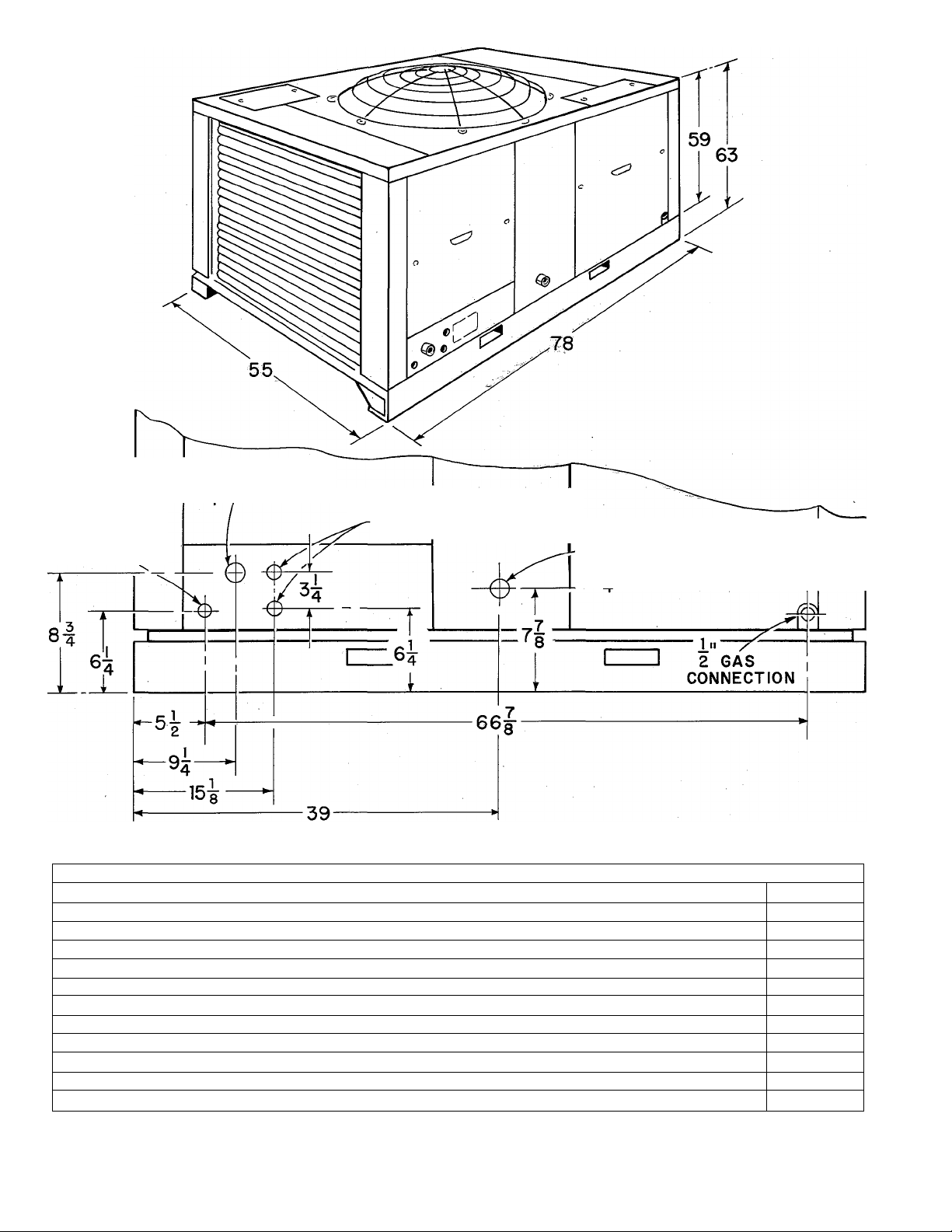
I. LOCATE AND MOUNT ABSORPTION UNIT
The absorption unit may be located at ground level
or on the roof. Consult local codes for information
concerning proximity to property lines, height above
roof, obstructions, etc.
A. MOUNTING BASE
1. Use non-combustible materials.
2. Suggested types of mounting base for ground
installation:
a. Precast concrete lintels.
Use three lintels the depth of unit, one each
urider right and left end of unit and one at center
of unit.
b. Concrete blocks.
Use one block at each corner of unit plus blocks
under the two long sides midway between the
corner blocks.
c. Concrete slab.
Minimum thickness 4 inches.
3. For installation on a roof or other combustible
material leave sufficient clearance between unit
sub-base and roof for proper air circulation. Use
precast concrete lintels or concrete blocks as
described in paragraph 2 above or steel beams.
Check local codes.
B. CLEARANCES
1. Absorption unit should
ance of 2 feet on all sides from any adjacent ob
struction.
2. Avoid locating the unit where hot condenser
discharge air can impinge on nearby obstructions
and mix with the inlet air supply. The condenser air
discharges upward. The unit should be located out
side of the plumb line from any over-hang.
II. CONNECT CHILLED WATER LINES
A. MATERIALS
Refer to section on “Freezing Weather Protection”
at the end of this instruction.
1. Piping
a. Polyethylene Plastic Pipe — use medium
density flexible pipe whose wall thickness ap
proximates Schedule 40 pipe (Commercial Stand
ard CS 197-60). Pipe must be virgin plastic. Do
not use pipe manufactured from re-claimed plas
tic.
b. Copper - satisfactory substitute.
c. Galvanized - satisfactory substitute.
2. Fittings
a. Galvanized - use when possible.
b. Brass - satisfactory substitute.
c. Nylon - satisfactory substitute.
REMOVE
hax&-.a_m.i.aijn.um—clear
Page 2
WATER OUTLET
ELECTRICAL CONNECTIONS
1"
2 GAS
CONNECTION
Cooling Capacity
Heat Input
Condenser Air Delivery CFM 14,000
Water Flow (minimum required) GPM
Maximum friction loss handled by Chiller Pump
Maximum elevation of coil above chiller
Pump Drive 230 v 60 cy 1 phase HP
Fan Drive 230 v 60 cy 1 phase HP
Minimum Wire Size *
Refrigerant Type
Refrigerant Amount
Approximate Shipping Weight
* Satisfactory where distance, measured along wire path, between unit and connection into main panel does not
exceed 100 ft. Where distances are longer, wire sizes should be increased accordingly.
I" KNOCKOUTS
WATER INLET
1 ”
IZ F.P.T.
108-451
BTUH
BTUH 330,000
Ft. Head
Ft.
AWG 12
LB 55
LB
108,000
22
45
49
1/3
1
717
2200
108/451
2-
Page 3
Table I
Nominal
Pipe Size
Inches
1
IVa
IV2
* Note: Values shown in above table are for one direction only. The total length of pipe from chiller to coil
and return would be double the above table values. The above table applies to single unit installations only.
B. PIPE LENGTH AND DIAMETER
Polyethylene Pipe
Size 108
48'
272'
610'
Table I shows maximum length of pipe of different
diameters that can be used between the pump dis
charge and the coil inlet and still maintain mini-,
mum allowable (design) water flow rate.
1. Multiply table values by two to obtain the total
length of pipe from chiller to coil and return.
2. Length is measured along the pipe path and
therefore includes vertical distance between the
water coil and the chiller.
Allowable Distance* Between Coil and Chiller
Copper Pipe
Size 108
67'
210'
492'
3. On installations where the outside piping freezes
and the coil is in a heated air stream, precautions
must be taken to provide for water expansion. The
connecting polyethylene plastic pipe acts as an
expansion vessel if there is enough footage of this
pipe in the heated space (space not subject to
freezing). The following table shows the minimum
lengths (total inlet and outlet) of plastic piping of
various diameters that are required for both sizes
of coils to provide adequate expansion volume.
Galvanized Pipe
Size 108
72'
285'
642'
3. Lengths shown in Table I are based on using a
total of eight elbows in the entire water line (chil
ler to coil and return). Lengths are predicated on the
use of a Bryant matching water coil. For greater
distances use larger pipe or add a pump.
C. INSULATION
1. Insulate supply and return lines separately.
2. Material should be of good quality and be covered
with a good vapor barrier. Armaflex or equivalent is
recommended.
Wall thickness:
1/2'' wall thickness - south of 40° N. latitude
Nominal Pipe Size
Inches
1
VA
Length of Plastic Pipe
in Feet
70
40
IV2 29
If the total plastic chilled water line footage in the
heated space is not as long as the minimum values
shown in the table, tee a vertical pipe of sufficient
volume into either of the coil connections to provide
for expansion, or the line should be drained.
3/8" wall thickness - north of 40° N. latitude
D. HEIGHT OF COIL
ABOVE ABSORPTION UNIT
Maximum vertical distance from chiller outlet to top
of coil is 49 feet. For greater heights, a greater
pumping head is required. Increasing the pipe size
will not help.
E. WATER COIL CONNECTIONS
1. If cooling coil is used in connection with heat
ing unit, install cooling coil in parallel with or
downstream of heating unit to avoid condensation in
the heating unit.
2. If coil is located in warm air stream, do not
connect polyethylene pipe directly to coil. Connect
a minimum of 24 inches copper or galvanized pipe
to both the coil inlet and outlet. Then connect the
plastic pipe to these nipples.
III. ELECTRIC CONNECTIONS
1. Make all electric connections in accordance with
the National Electrical Code and any local ordi
nances or codes that might apply.
2. Provide a separate power supply for the air
conditioner.
3. Provide a fused disconnect switch within sight
of and not more than 50 feet from the absorption
unit. Use 35 amp standard fuse.
4. The absorption unit is shipped fully wired from
the factory. Connection of 230V power and low volt
age connection to the thermostat control are re
quired in the field. Before proceeding, inspect
factory wiring for loose connections which may have
resulted during shipment.
- 3 -
108/451
Page 4

5. Figures 3 & 4 are the Wiring Diagrams for the
natural gas unit. Figures 5 8s 6 are the Wiring Dia
grams for an LPG unit.
6. Disconnect pump electrical lead at terminal 7
in front control box before energizing unit when
ready to check field wiring.
pump dry.
IV. GAS CONNECTIONS
Do not operate the
Consult local gas company before making any gas
connections. In case of conflict with this instruc
tion, local requirements should be followed.
Before selecting the size and type of pipe that is
to be used for installing the absorption unit, be
sure to check with local gas company for the neces
sary information. The size of the gas pipe to be
used between meter and unit will depend upon the
length of run and the allowable pressure loss estab
lished by the utility.
The gas connections to the unit are made at the
1/2 inch combination regulator-shut offs at each of
the two generators. The gas supply pipes enter the
unit through openings located at lower left rear and
lower right rear of unit. Install 1/2 inch ground
joint unions and 1/2 x 3/4 inch ells adjacent to
each combination regulator-shut off using two 1/2
inch X close nipples. The gas supply pipe from the
meter should terminate at the rear of the unit with a
tee. Install 3/4 inch pipe from this tee through the
openings in the rear casing to the 1/2 x 3/4 inch
ells adjacent to the regulator-shut offs at each
generator.
A. wrench-type shut-off valve should be installed in
the gas supply line within sight of, and convenient
to, the 451. It is recommended that ground joint
unions be installed in the gas supply piping just
outside the unit.
Joint compound (pipe dope) which is resistant to
the action of liquefied petroleum gases should be
applied sparingly and only to the male threads of
the joints.
After gas pipe connections have been made, purge
the lines and check for leakage. Use a soap and
water solution or other such material. Turn off
power supply to unit when purging the lines to
prevent glow coils in reignition pilots from being
energized. Never use matches, candles, flame or
other source of ignition to check leakage.
PILOT
The natural gas unit is equipped with two reignition
type pilots (one pilot in each generator). The pilots
will light automatically when supplied with gas and
are electrically energized. The circuit is arranged
to light the pilots sequentially. Several minutes
must be allowed for the first pilot to ignite and
make contact before second pilot will be energized.
To manually light the pilots use the procedure out
lined on the Lighting Instruction Plate attached to
generators. The pilot flame should be soft blue in
color. The flame should be of sufficient length to
provide good impingement on the unimetal element
of the Bryant pilot. Flame should extend upward
between the carry-over ports of the two adjacent
burners.
If the pilot flame does not have the appearance
described above, it may be adjusted by means of
the manual pilot shut-off valve which is equipped
with an adjustable screw. Turn the handle to the
full-open position and remove the screw cap on the
valve handle, thus exposing the adjustable screw.
Turn adjusting screw until flame has the desired
appearance. Replace screw cap.
V. CHARGING THE SYSTEM WITH WATER
Caution: Do not run the pump dry. Freezing con
ditions will not damage the pump; however, do not
attempt to operate the pump when chiller or chilled
water lines are frozen.
1. Turn off main manual gas shut-off valve.
2. Remove the filler caps located on top of both
chiller tanks.
3. Disconnect water line at chiller inlet. (When
installing the chilled water lines, it is advisable to
leave this connection open until lines have been
flushed.)
4. Fill tanks with tap water through the filler
opening of one tank until the distributor pans are
covered with water. A garden hose is useful for this
filling operation.
5. Start pump. Continue to supply water to the tank
and operate pump until all foreign matter has beeii
flushed from the lines. Then remove hose.
Note: If water does not circulate when the pump
is started, air may be trapped in the pump. Bleed
the air from pump through the 1/8 inch slotted head
108/451
-4-
Page 5

FILLER CAP
FILLER CAP
,.y
bleed valve located on top of the pump discharge.
Open valve with screwdriver. Close valve when the
trapped air is removed and water appears.
6. Remove operating level drain plug of either
chiller and continue to operate pump until water
stops flowing from drain opening.
7. Turn off pump. Make pipe connection to chiller
inlet.
8. Replace operating level drain plug finger tight.
Add several gallons of water to tanks to raise water
level above drain opening.
9. Start pump. Adjust water level with pump running.
This is accomplished by removing one drain plug.
When water ceases to drain, the level is properly
adjusted in both chiller tanks.
10. Add contents of two chilled water additive
packages to chiller tank through filler opening at
top of tank. The two packages supplied is sufficient
for chilled water systems containing up to 40 gallons
of water. For systems larger than 40 gallon capa
city, add 1/2 package for each additional 10 gallon
\
capacity or fraction thereof. To estimate chilled
water capacity of system refer to Table II.
n. Replace filler caps.
12. The system is now ready to operate.
Table II
Water Capacity in Gallons
108-451 Chiller
Bryant 1ton coil
...........................................
...
..............................................0.6
...
19.4
Bryant 3 ton coil........................................................1.0
Bryant 4^/i ton coil
....
..............................................1.5
Bryant 9 ton coil........................................................3.0
1 ft. of 1 inch pipe
1 ft. of I'A inch pipe
...............................................
.........................
........................0.08
. 0.05
1 ft. of inch pipe...................................................... 0.11
VI. CHECK OUT AND OPERATION
1. Be sure main manual gas valve is off. Light
pilots as described on instruction plate.
2. Set thermostat to ‘cool’; set thermostat fan
switch to ‘auto’; set thermostat below room tem
perature.
3. Turn on main electric switch to unit.
. 5 - 108/451
Page 6

4. Check indoor fan operation by turning thermo
stat fan switch to ‘on’ for continuous fan operation.
Move thermostat above room temperature and observe
that the indoor fan remains on.
5. To place the system in operation, open the main
manual gas valve, replace all panels, and set the
thermostat at the desired temperature.
High Temperature Cut-Off
The high temperature circuit includes two high
temperature controls - one located on the front of
each generator plus a high temperature relay (lockout
relay) located in the front control box. If either
generator becomes overheated the contacts in its
high temp control open, causing the high temp relay
to go ¿nto lockout position. The gas valves close,
the fan and pump stop, and will not recycle until
the lockout relay is reset. To reset lockout relay
turn electric power off and then back on. Be sure
to locate and correct cause of high temp cut-out.
Example: Natural Gas
1025 BTU
0.63 specific Gravity
1. From Table III manifold pressure is 3.2 inches
w.c.
2. With manometer connected to manifold ‘A’ set
pressure at 3.2 inches by adjusting gas pressure
regulator.
3. With manometer connected to-manifold ‘B’ set
pressure at 3.2 inches by adjusting gas pressure
regulator. ^
Table III-Manifold Pressure
(Inches w.c.)
Specific Gravity
0.59 0.61
900
■ 3.9"
950 3.5" 3.6" 3.7" 3.8"
1000
1025
ca
1050
1100 2.6" 2.7"
3.1"
3.0"
2.8" 2.9"
4.0"
3.2" 3.3" ,
3.1" 3.2" 3.3" 3.4"
0.63 0.65 0.67
4.1"
3.0"
2.8"
4.2"
3.4" 3.5"
3.1" 3.2"
2.9" 3.0"
4.3"
3.9"
VII. ADJUST GAS INPUT
The gas input of the Model 108-451 is 330,000 BTUH
or 165,000 BTUH for each of the two generators.
For operation on natural gas the burners are equip
ped with fixed orifices drilled #39. The adjustable
gas pressure regulator is set at the factory for 3.0
inches w.c. manifold pressure.
It is necessary to check manifold pressures with a
manometer, whether the gas is measured at the meter
or the input is set by manifold pressure according
to Table III.
When measuring gas at the meter also check pres
sures at both generator manifolds with a manometer.
The pressures at both manifolds must read the same
to insure equal input to each generator. A 1/4 inch
pressure tap is located on each manifold for con
necting the manometer.
If it is not possible to, measure the gas input at the
meter refer to Table III to procure the manifold
pressure required for the btu value and specific
gravity of the gas to be supplied to the unit. With
the manometer connected to one manifold set the
pressure by adjusting the gas pressure regulator.
Repeat the same procedure to set the pressure at
the manifold of the second generator.
VIII. BALANCE THE SYSTEM
After the unit is in operating and the input has been
measured and adjusted to agree with the rating
plate requirements, balance the system.
Any approved method of checking the air flow over
the water coil may be utilized. Reference is made
to the Bryant Service Manual on Gas Air Condi
tioners for a review of standard methods.
108/451
- 6-
Page 7

IX. PURGE NON-CONDENSIBLES
FREEZING WEATHER PROTECTION
Purging is accomplished through valves A on inlet
tanks and valves D on purge pots. Each refrigera
tion circuit must be checked.
Operate unit for a minimum of 15 minutes. While
still operating, proceed as follows:
1. Attach adapter and purge line to valve A.
2. Run purge line to bucket of water.
3. Remove cap and open valve A about 1/8 to 1/4
turn.
4. If non-condensibles are present, bubbles will
rise to the surface of the water in the bucket.
5. Leave valve A open as long as bubbles rise
to the surface of the water. When non-condensibles
are removed the bubbles will cease as ammonia
will be absorbed into the water.
6. Close valve A.
7. Open valve D about 1/8 turn. Usually there will
be some solution trapped in the valve body, and this
solution will be released as soon as the valve is
opened.
8. If non-condensibles are present they will follow
the initial surge of solution. When solution reappears
in quantity, the non-condensibles trapped in the
purge pot have been released.
9. Close valve D.
10. Repeat procedure for other circuit.
The installation should now be complete.
Gas Air Conditioner
The Gas Air Conditioner has built-in freeze pro
tection sufficient to protect the chiller and pump
plus a small amount of external hard (non-plastic)
pipe as shown in Figure 2.
Chilled Water Pipes
If hard pipe (non-plastic) is used for the chilled
water lines, it will be necessary to drain the lines
or add anti-freeze. The recommended anti-freeze is
methanol (uninhibited methyl alcohol). Since the
fluid will not be pumped, only enough methanol is
required to form slush. Add one gallon-of methanol
for each 20 gallons of water or fraction thereof,
and circulate 10 minutes. The chilled water additive
(Borax) must be used in the same proportion as
indicated in Section V when anti-freeze treatment
is required.
Chilled Water Coil
If water coil is subject to freezing temperatures,
it will be necessary to protect the coil by the ad
dition of anti-freeze. Chilled water coils cannot
be completely drained. Add one gallon of methanol
for each 20 gallons of water or fraction thereof,
and circulate 10 minutes. The chilled water addi
tive (Borax) must be used in the same proportion
as indicated in Section V when anti-freeze treatment
is required.
Operation at Freezing Temperatures
If the air conditioning system is to operate under
freezing conditions, it will be necessary to add
methanol in the amount required to protect to the
lowest outdoor temperature. Consult your Bryant
distributor for recommended procedure.
- 7-
108/451
Page 8

o
OQ
Oi
Figure 3 - Unit Wiring Natural Gas
With Reignition
Control Box A
Page 9

HIGH
PRESS.
CUTOUT
m
X Y G
1
1»
•
( » 1f
R
CONTROL BOX'S'
BLUE
BROWN
YELLOW
BLACK
BROWN
SCHEMATIC WIRING DIAGRAM
X OF 108-451
/
GAS
VALVE
GAS PRESSURE
SWITCH
--------------------y-----------------
TO CONTROL BOX NO. A
FACTORY LINE VOLTAGE
FACTORY LOW VOLTAGE '
1. PRESSURE SWITCHES
2. PILOT
3. GLOW COIL
4. GAS PRESS. SW.
5. RESISTOR
6. GAS VALVE
7. POWER RELAY COIL
8. TRANSFORMER
9. THERMOSTAT OVERRIDE SW. 18. PART LOAD CONTROL
10.
THERMOSTAT
11.
HI-TEMP RELAY
12.
HI-TEMP CUTOUT
13.
FAN MOTOR
PUMP MOTOR
14.
15.
TIMER MOTOR
16.
TIMER SWITCH
17.
POWER RELAY
HIGH TEMP.
CUTOUT
REIGNITION
PILOT SWITCH
\
o
YELLOW
BLACK
BLUE
0
597saci
o
00
Figure 4 - Unit Wiring Natural Gas - Control Box B
With Re ignition
Page 10

o
00
4^
cn
Figure 5 - Unit Wiring LP Gas - Control Box A
No Reignition
Page 11

! CONTROL BOX "B'
12B;
SCHEMATIC WIRING DIAGRAM
X
m-
OF 108-451
BROWN
YELLOW
BLACK
BROWN
YELLOW
HIGH
PRESSURE
CUTOUT
•------
12A
11
9 ^ ;:i0
IB
“I
I
o R
OY
18
: 16A
\
/
2A
J
6B
# 1À
17
r —
• 1
IT
L
____
en 2B
HI PRESS.
VALVE
K>
HIGH TEMP
CUTOUT
PILOT SWITCH
O
Oo
in
■ o
YELLOW
BLACK
0
GAS
VALVE
Y
--------------
TO CONTROL BOX NO. A
FACTORY LINE VOLTAGE
FACTORY LOW VOLTAGE
Figure 6 - Unit Wiring LP Gos - Control Box B
No Reignition
L_ J
G
1.
PRESSURE SWITCHES
2. PILOT
3.
GLOW COIL
4.
GAS PRESS. SW.
5.
RESISTOR
6.
GAS VALVE
7.
POWER RELAY COlL
8.
TRANSFORMER
9.
THERMOSTAT OVERRIDE SW.
10.
11.
12.
13.
14.
15.
16.
17.
18.
■
S076OCI
 Loading...