

Page 1

Chapter
Chapter
BX-MBIO MOdBus I/O
Chapter
COntrOller
15
15
15
In This Chapter...
Overview ..................................................................................................................................................... 15-2
BX-MBIO I/O Controllers ............................................................................................................................ 15-3
General Specifications ............................................................................................................................. 15-3
Serial Port Connector .............................................................................................................................. 15-4
Power Supply Connector ........................................................................................................................ 15-5
Power Supply Specifications for BX-MBIO-M ......................................................................................... 15-6
Power Supply Connections ..................................................................................................................... 15-6
Power Supply Specifications for BX-MBIO-M-D ..................................................................................... 15-7
Power Supply Connections ..................................................................................................................... 15-7
Configuration .............................................................................................................................................. 15-8
DIP Switch Specifications ........................................................................................................................... 15-8
Status Indicators ......................................................................................................................................... 15-9
Modbus Protocol Function Codes Supported by BX-MBIO .................................................................... 15-10
Modbus Protocol Exception Responses ................................................................................................... 15-13
Modbus RTU, Serial Communications......................................................................................................15-15
Modbus TCP, Ethernet Communications ................................................................................................. 15-20
BX-MBIO Configuration ........................................................................................................................... 15-20
Troubleshooting with Modbus Poll.......................................................................................................... 15-34
Detailed Example: Using the Modbus Poll Utility to Verify Communications With BX-MBIO .......... 15-34
Additional BX-EBC100 and BX-MBIO Modbus Mapping Information .................................................... 15-45
Modbus Mapping for I/O ...................................................................................................................... 15-45
System Memory Modbus Mapping ...................................................................................................... 15-45
Error Codes ........................................................................................................................................... 15-47
Page 2
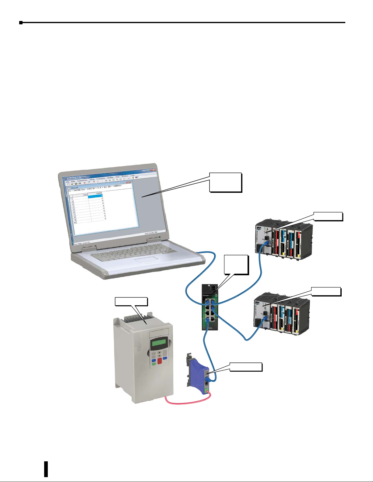
Chapter 15: BX-MBIO Modbus I/O Controller
BX-MBIO Modbus PCP Remote IO Network.eps
Overview
The BX-MBIO Modules are remote I/O controller modules that provides a remote I/O drop using the
Modbus protocol for communications. They are Modbus RTU slave devices and Modbus TCP servers. They
function as listening/replying devices and can connect with any mastering (client) device that communicates
using the Modbus protocol.
Modbus RTU is supported over an RS-485 serial connection. Modbus TCP is supported over an Ethernet
connection. Any Modbus RTU master and Modbus TCP client that adheres to the Modbus.Org standards,
and support the function codes listed in this chapter, can communicate with the BX-MBIO.
The units have no built-in I/O points. The user can customize the I/O to meet the needs of their application
by adding as many as eight (8) BRX Expansion Modules, allowing more flexibility while keeping control
costs down.
Modbus TCP
Master Poll
Utility
Stride
Ethernet
Switch
GS3 AC Drive
GS-EDRV100
BX-MBIO-x
OUTPUT
IN/OUT
1C
I0+
1C
I1+
0
1C
I0+
I2+
1
Y
2
3
2C
4
5
Y
6
7
3C
8
9
Y
10
11
BX-12TD1
I1+
0
I3+
I2+
1
X
I3+
I4+
2
I5+
3
I6+
2C
I7+
4
5
X
6
7
1C
0
1
Y
2
3
BX-12CD3D1
BX-MBIO-x
OUTPUT
IN/OUT
1C
I0+
0
I1+
1C
1C
I2+
1
Y
2
3
2C
4
5
Y
6
7
3C
8
9
Y
10
11
BX-12TD1
I0+
0
I3+
I1+
I2+
1
X
I4+
I3+
2
I5+
3
I6+
I7+
2C
4
5
X
6
7
1C
0
1
Y
2
3
BX-12CD3D1
15-2
BRX User Manual, 4th Edition, Rev. F
Page 3
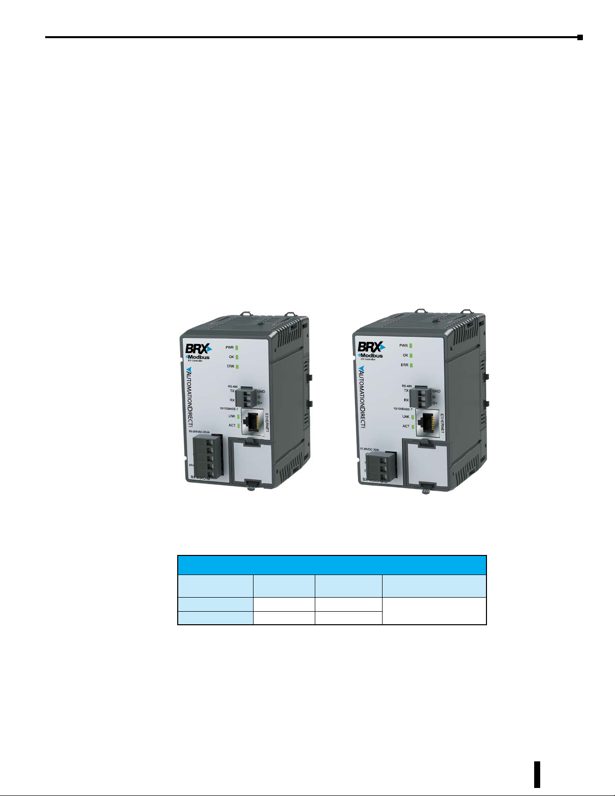
BX-MBIO I/O Controllers
General Specifications
• RJ45 Ethernet port for communications via Modbus TCP
• RS485 serial port for communications via Modbus RTU
• No support for Pluggable Option Module (POM)
• Supports up to 8 additional Expansion Modules
• No built-in discrete or analog I/O
• AC and DC powered units available
• AC powered units include an integral 24VDC auxiliary output power supply
• Power connector and serial port connector included
Chapter 15: BX-MBIO Modbus I/O Controller
BX-MBIO-M
Modbus I/O Controller
BX-MBIO Controllers
Part Number
BX-MBIO-M 120–240 VAC 8
BX-MBIO-M-D 12–24 VDC 8
BRX User Manual, 4th Edition, Rev. F
External
Power
Expansion
Modules
BX-MBIO-M-D
Modbus I/O Controller
Can be Used With
Modbus RTU
Modbus TCP
15-3
Page 4
Chapter 15: BX-MBIO Modbus I/O Controller
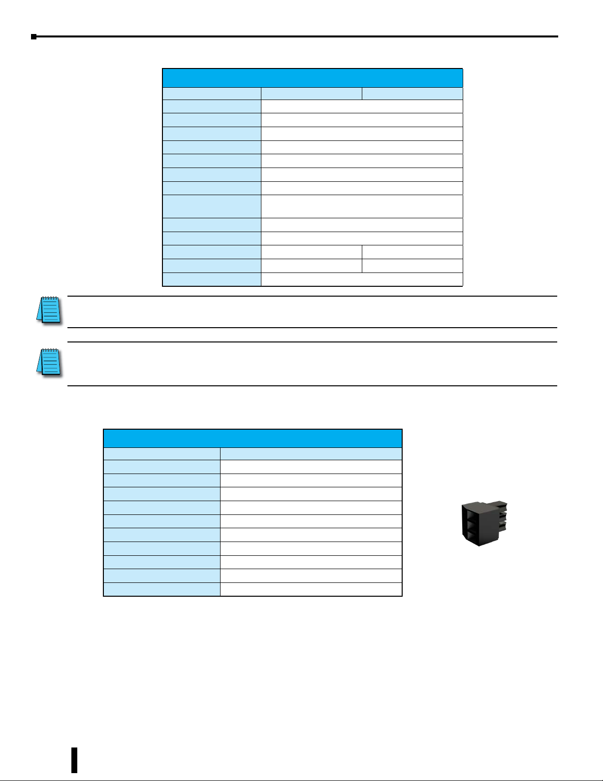
General Specifications, continued
General Specifications
Part Number BX-MBIO-M BXC-MBIO-M-D
Operating Temperature 0° to 60°C (32° to 140°F)
Storage Temperature -20° to 85°C (-4° to 185°F)
Humidity 5 to 95% (non-condensing)
Environmental Air No corrosive gases permitted
Vibration IEC60068-2-6 (Test Fc)
Shock IEC60068-2-27 (Test Ea)
Enclosure Type Open Equipment
Agency Approvals
Noise Immunity NEMA ICS3-304
EU Directive See the “EU Directive” topic in the Help File
Heat Dissipation 10.8 W Max 8.6 W Max
Weight 198g (7oz) 170g (6oz)
Software Version NetEdit Version 3.15 or later
NOTE: Eight (8) Expansion Modules can be connected to add I/O capability. Only Discrete and Analog Expansion
Modules are supported.
UL61010-2 - UL File # E185989 Canada and USA
CE Compliant EN61131-2
NOTE: If you are a Do-more! user and are looking to add additional remote I/O you should consider the BX-DMIO or
the BX-EBC100 for a lower cost and easier installation and startup. (See Chapter 14 for more detail.) The BX-MBIO
Controllers are designed for systems that use Modbus Clients as remote I/O drops.
Serial Port Connector
BX-MBIO Serial Port Connector Specifications
Part Number BX-RTB03S
Connector Type Screw Type-90° (included with unit)
Wire Exit 180 deg
Pitch 3.5 mm
Screw Size M2
Recommended Screw Torque < 1.77 lb·in (0.2 N·m)
Screwdriver Blade Width 2.5 mm
Wire Gauge (Single wire) 28-16 AWG
Wire Gauge (Two wires) 28-16 AWG
Wire Strip Length 0.24 in (6mm)
Equiv. Dinkle P/N EC350V-03P-BK
BX-RTB03S
15-4
BRX User Manual, 4th Edition, Rev. F
Page 5
Chapter 15: BX-MBIO Modbus I/O Controller
Power Supply Connector
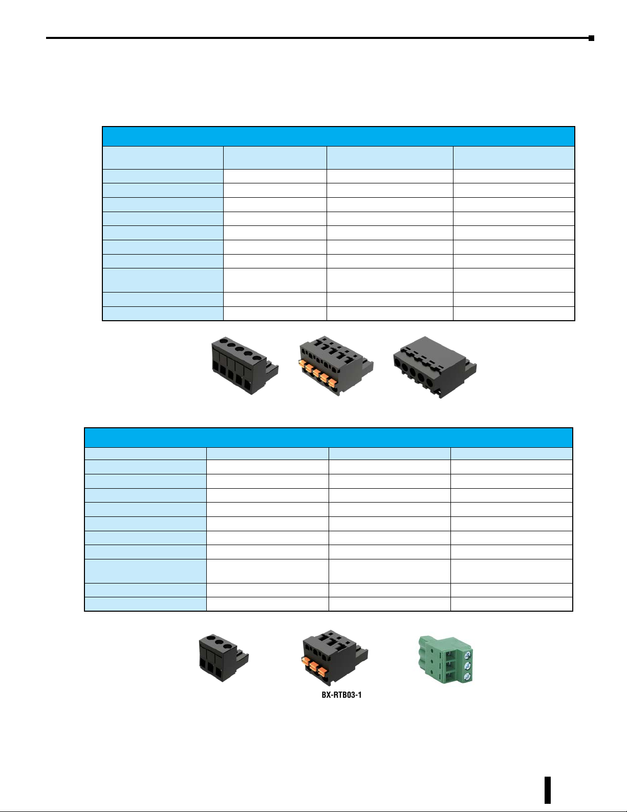
The power supply terminal block connector is included with each controller. The power supply connector
is a screw type, removable terminal block. Replacement connectors and specifications are listed in the tables
that follow.
BX-MBIO-M AC Power Supply Connector Specifications
Part Number
Connector Type Screw Type-90 deg Spring Clamp Type-180 deg Screw Type-180 deg
Wire Exit 180 deg 180 deg 180 deg
Pitch 5.0 mm 5.0 mm 5.0 mm
Screw Size M2.5 N/A M2.5
Recommended Screw Torque < 3.98 lb·in (0.45 N·m) N/A < 3.98 lb·in (0.45 N·m)
Screwdriver Blade Width 3.5 mm 3.5 mm 3.5 mm
Wire Gauge (Single wire) 28–12 AWG 28–14 AWG 28–14 AWG
Wire Gauge (Two wire) 28–16 AWG
Wire Strip Length 0.3 in (7.5 mm) 0.37 in (9.5 mm) 0.37 in (9.5 mm)
Equiv. Dinkle P/N 5ESDV-05P-BK 5ESDSR-05P-BK 5ESDF-05P-BK
BX-RTB05
(Included w/Unit)
BX-RTB05-1 BX-RTB05-2
(Dual Wire Ferrule Required)
28–16 AWG
(Dual Wire Ferrule Required)
28–16 AWG
BX-RTB05-2BX-RTB05-1BX-RTB05
BX-MBIO-M-D DC Power Supply Connector Specifications
Part Number BX-RTB03 (Included w/Unit) BX-RTB03-1 BX-RTB03-2
Connector Type Screw Type-90 deg Spring Clamp Type-180 deg Screw Type-180 deg
Wire Exit 180 deg 180 deg 180 deg
Pitch 5.0 mm 5.0 mm 5.0 mm
Screw Size M2.5 N/A M2.5
Recommended Screw Torque < 3.98 lb·in (0.45 N·m) N/A < 3.98 lb·in (0.45 N·m)
Screwdriver Blade Width 3.5 mm 3.5 mm 3.5 mm
Wire Gauge (Single wire) 28–12 AWG 28-14 AWG 28-12 AWG
Wire Gauge (Two wires) 28–16 AWG
Wire Strip Length 0.3 in (7.5 mm) 0.37 in (9.5 mm) 0.3 in (7.5 mm)
Equiv. Dinkle P/N 5ESDV-03P-BK 5ESDSR-03P-BK 5ESDF-03P
BX-RTB03
28-16 AWG
(Dual Wire Ferrule Required)
BX-RTB03-1
28-16 AWG
BX-RTB03-2
BRX User Manual, 4th Edition, Rev. F
15-5
Page 6
Chapter 15: BX-MBIO Modbus I/O Controller
300mA max.
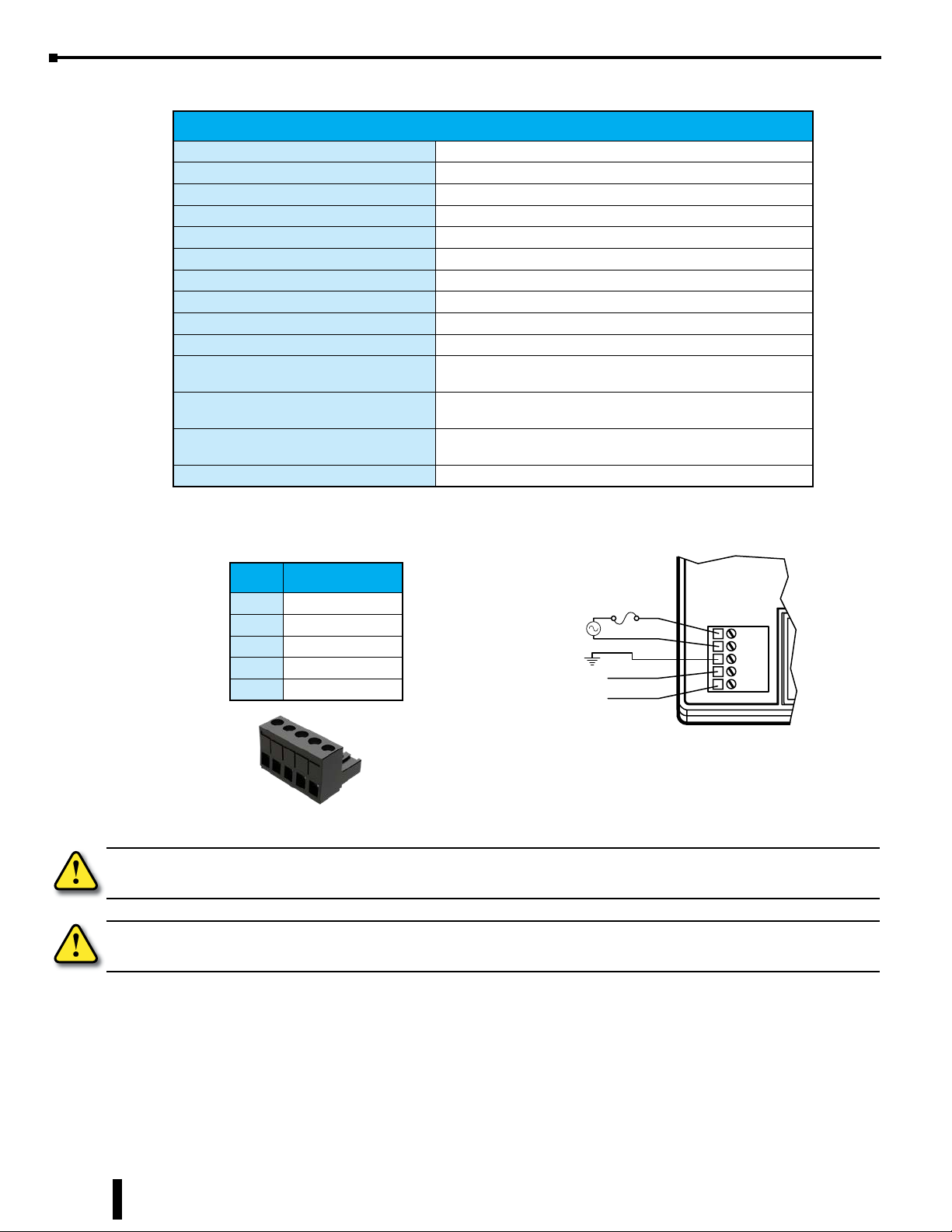
Power Supply Specifications for BX-MBIO-M
BX-MBIO-M Power Supply Specifications
Nominal Voltage Range 120–240 VAC
Input Voltage Range (Tolerance) 85–264 VAC
Rated Operating Frequency 47–63 Hz
Maximum Input Power 40VA
Cold Start Inrush Current 1.5 A, 2ms
Maximum Inrush Current (Hot Start) 1.5 A, 2ms
Internal Input Fuse Protection Micro fuse 250V, 2A Non-replaceable
Acceptable External Power Drop Time 10ms
Under Input Voltage Lock-out 80VAC
Input Transient Protection Input choke and line lter
Output Protection for Over Current, Over
Voltage, and Over Temperature
Auxiliary 24VDC Output
Voltage Withstand (dielectric)
Insulation Resistance >10MΩ @ 500VDC
Self resetting
24VDC @ 0.3 A max, <1V P-P Ripple, Integrated self-resetting
short circuit protection, Isolated
1500VAC Power Inputs to Ground applied for 1 minute
1500VAC Ground to 24VDC Output applied for 1 minute
Power Supply Connections
Pin Connection
1 L
2 N
3 GND
4 V–
5 V+
Removable Connector Included
ADC Part # BX-RTB05
WARNING: Do not exceed the 24VDC auxiliary power supply load limit of 300mA.
WARNING: The BRX System MUST have a proper earth ground. Do not operate the BRX MPU without proper
earth grounding.
AC Power In
120–240 VAC
–
+
Auxillary out
24VDC
L
N
GND
VV+
15-6
BRX User Manual, 4th Edition, Rev. F
Page 7
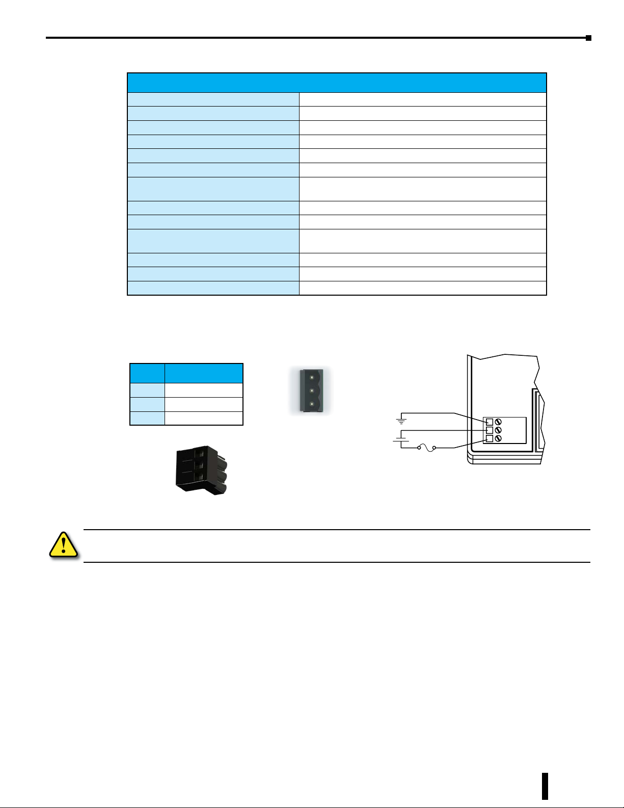
Power Supply Specifications for BX-MBIO-M-D
BX-MBIO-M-D Power Supply Specifications
Nominal Voltage Range* 12–24 VDC
Input Voltage Range (Tolerance)* 10–36 VDC
Maximum Input Voltage Ripple < ±10%
Maximum Input Power 30W
Cold Start Inrush Current 5A, 2ms
Maximum Inrush Current (Hot Start) 5A, 2ms
Internal Input Protection
Acceptable External Power Drop Time 10ms
Under Input Voltage Lock-out <9VDC
Output Protection for Over Current, Over
Voltage, and Over Temperature
Auxiliary 24VDC Output None
Voltage Withstand (dielectric) 1500VAC power Inputs to ground applied for 1 minute
Insulation Resistance >10MΩ @ 500VDC
* Class 2 or LPS Power Supply required.
Reverse polarity protection and undervoltage lockout via
Chapter 15: BX-MBIO Modbus I/O Controller
transistor circuit
Self resetting
Power Supply Connections
Class 2 or LPS
Pin Connection
1 GND
2 PWR –
3 PWR +
Removable Connector Included
ADC Part # BX-RTB03
WARNING: The BRX System MUST have a proper earth ground. Do not operate the BRX MPU without proper
earth grounding.
User Supplied Power
DC Power In
12–24 VDC
+
GND
PWRPWR+
BRX User Manual, 4th Edition, Rev. F
15-7
Page 8
Chapter 15: BX-MBIO Modbus I/O Controller
7 6 5 4 3 2 1 0
Configuration
The BX-MBIO controller can be configured as a serial Modbus RTU slave or as a Ethernet Modbus TCP server.
As a Modbus RTU serial slave you can simply use the dip switches and set the module ID. Using the default
settings no other setup is needed. Any changes to the configuration of the controller is done through the
Ethernet port using the NetEdit 3 utility to get access to the web configuration page of the controller. See
Appendix E if needed on how to use the NetEdit 3 utility to gain this access.
Default settings:
• The serial port - 115,200 baud, 8 data bits, parity None, 1 stop bit
• The attached expansion modules - see the expansion module specifications for the default
settings for each module.
As a Modbus TCP Ethernet server the NetEdit 3 utility will be needed to set the Ethernet settings and to
gain access to the web configuration page. See appendix E if needed on how to use the NetEdit 3 Utility to
gain this access.
DIP Switch Specifications
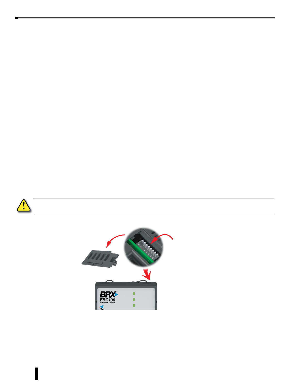
The BX-MBIO Modbus I/O controller has a block of DIP switches, located on the top of the chassis, that
are used to setup the serial port station number, write protect the module and disable the Web configuration
page. The DIP switch settings are read when the system is powered up. The default position for all DIP
switches is OFF.
WARNING: The BX-MBIO Modbus I/O controller must be powered down prior to changing DIP switch settings.
NOTE: DIP switches located in
this compartment are used for
controller configuration.
PWR
OK
ERR
15-8
BRX User Manual, 4th Edition, Rev. F
Page 9
Chapter 15: BX-MBIO Modbus I/O Controller
76543210
6
5
4
3
2
0
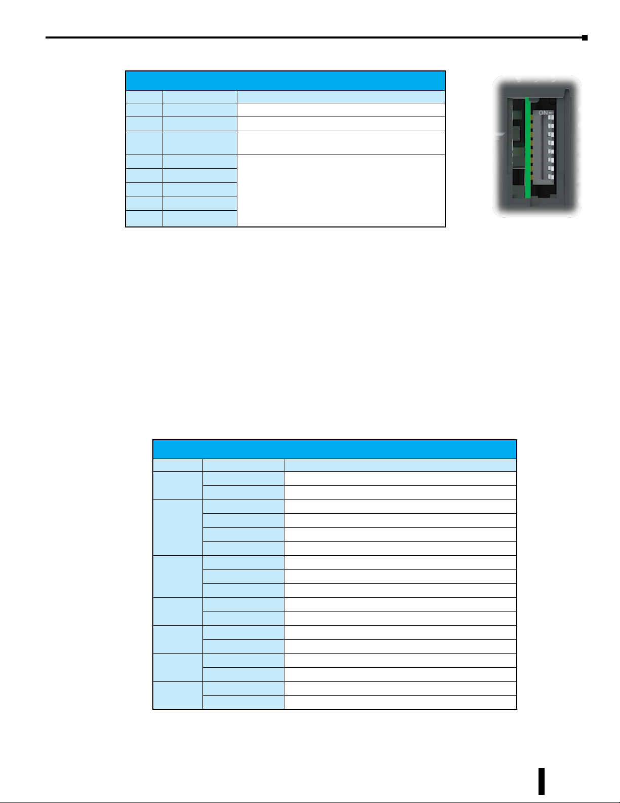
The following table describes the position and function associated with each DIP switch.
DIP Switch Settings
DIP# Switch Position Function
7 ON Reserved
6 ON Reset the module to factory default
5 ON
4 ON Station number:
3 ON
2 ON
1 ON
0 ON
Write protect the module. No writes to ash memory
are allowed. Disable Web conguration page.
DIP Switch 0–4: Supports addresses 1 to 31.
All DIP Switch OFF:
Station number from ash.
Enter via Netedit 3 or Web conguration page.
Supports addresses 1 to 247.
DIP Switch position is read when power is applied to the module. Power down the module before changing
DIP switch settings.
DIP switches 0 to 4: Use to set a fixed serial port station number, from 1 to 31. If all five switches are left
in the OFF position, the station number will be read from the module flash. The user can use the utility
NetEdit 3 or, if enabled, the user can use the Web configuration page to set the RS-485 station number, from
1 to 247.
7
1
DIP Switch 5: When ON, it will write protect the module. It will not be possible to update the network
settings, update the firmware or the booter version. It also disables access to the Web configuration page.
DIP Switch 6: When ON, the module is reset to factory defaults.
Status Indicators
BX-MBIO Status Indicators
Indicator Status Description
PWR
OK
ERR
TX
RX
LNK
ACT
OFF Base Power is OFF
GREEN Base Power is Good
GREEN Controller is Functioning Normally
GREEN (Blinking) Reset Mode (Booter without OS)
YELLOW Analog Module Mismatch
OFF Controller HW Error or Power is OFF
OFF Controller is Functioning Normally
RED Controller HW Error or Communications Watchdog Timeout
RED (Blinking) Reset Mode (Booter without OS)
OFF No Transmit Activity
GREEN (Blinking) Data is being Transmitted
OFF No Receive Activity
GREEN (Blinking) Data is being Received
OFF No Ethernet Link
GREEN Ethernet Link is Good
OFF No Ethernet Activity
GREEN (Blinking) Ethernet Activity
BRX User Manual, 4th Edition, Rev. F
15-9
Page 10

Chapter 15: BX-MBIO Modbus I/O Controller
Modbus Protocol Function Codes Supported by BX-MBIO
Modbus Protocol Function Codes
Function Type
Read Coil Status 01 01
Read Input Status 02 02
Read Holding Registers 03 03
Read Input Registers 04 04
Force Single Coil 05 05
Preset Single Register 06 06
Force Multiple Coils 15 0F
Force Multiple Registers 16 10
Mask Write Register 22 16
NOTE: Please visit Modbus.org to get information on the latest revision of the Modbus Protocol Specifications.
Modbus Function Code
(Decimal) (Hex)
Function 01 (0x01) Read Coils
This function code is used to read the status of a block (1 to 2000) of contiguous coils (bits) in a remote
device. Depending on the type of Modbus slave, coils can be used as internal bits or physical discrete outputs.
Modbus data type identifier: 0xxxxx
Modbus address range: 000001 to 065536
Example: Coil 17 is referred to as 000017
Function 02 (0x02) Read Discrete Inputs
This function code is used to read the status of a block (1 to 2000) of contiguous discrete inputs (bits) in a
remote device.
Modbus data type identifier: 1xxxxx
Modbus address range: 100001 to 165536
Example: Discrete input 31 is referred to as 1000031
Function 03 (0x03) Read Holding Registers
This function code is used to read the contents of a block (1 to 125) of contiguous holding registers in a
remote device. Holding registers are 16 bit words. Depending on the Modbus slave, Holding Registers may
be used to address Analog Outputs or used as general purpose registers to store values in the program.
15-10
Modbus data type identifier: 4xxxxx
Modbus address range: 400001 to 465536
Example: Holding Register 2035 is referred to as 402035
BRX User Manual, 4th Edition, Rev. F
Page 11

Chapter 15: BX-MBIO Modbus I/O Controller
Modbus Protocol Function Codes Supported by BX-MBIO, continued
Function 04 (0x04) Read Input Registers
This function code is used to read the contents of a block (1 to 125) of contiguous input registers in a remote
device. Input Registers are 16 bit words. Depending on the Modbus slave, they may be used to address
Analog Inputs or read-only values.
Modbus data type identifier: 3xxxxx
Modbus address range: 300001 to 365536
Example: Input Register 1027 is referred to as 301027
Function 05 (0x05) Write Single Coil
This function code is used to write a single output to either ON or OFF in a remote device. Depending on
the type of Modbus slave, coils can be used as internal bits or physical discrete outputs.
Modbus data type identifier: 0xxxxx
Modbus address range: 000001 to 065536
Example: Coil 17 is referred to as 000017
Function 06 (0x06) Write Single Register
This function code is used to write a single holding register in a remote device. Holding registers are 16-bit
words. Depending on the Modbus slave, Holding Registers may be used to address Analog Outputs or used
as general purpose registers to store values in the program.
Modbus data type identifier: 4xxxxx
Modbus address range: 400001 to 465536
Example: Holding Register 2035 is referred to as 402035
Function 15 (0x0F) Write Multiple Coils
This function code is used to force each coil in a sequence (1 to 1968) of coils (bits) to either ON or OFF
in a remote device. Depending on the type of Modbus slave, coils can be used as internal bits or physical
discrete outputs.
Modbus data type identifier: 0xxxxx
Modbus address range: 000001 to 065536
Example: Coil 64 is referred to as 000064
Function 16 (0x10) Write Multiple Registers
This function code is used to write a block (1 to 123 registers) of contiguous Holding Registers in a remote
device. Holding registers are 16 bit words. Depending on the Modbus slave, Holding
Registers may be used to address Analog Outputs or used as general purpose registers to store values in the
program.
BRX User Manual, 4th Edition, Rev. F
15-11
Page 12

Chapter 15: BX-MBIO Modbus I/O Controller
Modbus Protocol Function Codes Supported by BX-MBIO, continued
Modbus data type identifier: 4xxxxx
Modbus address range: 400001 to 465536
Example: Holding Register 2035 is referred to as 402035
Function 22 (0x16) Mask Write Register
This function code is used to modify the contents of a specified holding register using a combination of
an AND mask, an OR mask, and the register’s current contents. The function can be used to set or clear
individual bits in the register.
The request specifies the holding register to be written, the data to be used as the AND mask, and the data
to be used as the OR mask.
The function’s algorithm is:
Result = (Current Contents AND And_Mask) OR (Or_Mask AND (NOT And_Mask))
For example:
Mask Write Register Example
Hex Binary
Current Contents 12 0001 0010
And_Mask = F2 1111 0010
Or_Mask = 0D 0000 1101
(NOT And_Mask) = 17 0001 0111
Result = 17 0001 0111
Note:
• If the Or_Mask value is zero, the result is simply the logical ANDing of the current contents and
And_Mask. If the And_Mask value is zero, the result is equal to the Or_Mask value.
• The contents of the register can be read with the Read Holding Registers function (function code
03). They could, however, be changed subsequently as the controller scans its user logic program.
Modbus data type identifier: 4xxxxx
Modbus address range: 400001 to 465536
Example: Holding Register 2035 is referred to as 402035
15-12
BRX User Manual, 4th Edition, Rev. F
Page 13

Modbus Protocol Exception Responses
Except for a broadcast message, when a client (master) device sends a request to a server (slave) device it
expects a normal response. One of four possible events can occur from the client’s (master) query:
• If the server (slave) device receives the query without a communication error, and can handle the
query normally, it returns a normal response.
• If the server (slave) does not receive the query due to a communication error, no response is returned.
The client (master) will eventually process a timeout condition for the request. (Timeout is fixed at
800ms. Once the first character arrives, the controller waits 800ms for the entire request to arrive.)
• If the server (slave) receives the query, but detects a communication error (parity, LRC, CRC, ...), no
response is returned. The client (master) will eventually process a timeout condition for the request.
(Timeout is fixed at 800ms. Once the first character arrives, the controller waits 800ms for the entire
request to arrive.)
• If the server receives the query without a communication error, but cannot handle it (for example,
if the request is to read a non–existent coil or register), the server (slave) will return an Exception
Response informing the client (master) of the nature of the error. This Exception Response value
from the server (slave) can optionally be stored in a memory location. The BX-MBIO uses a 1-byte
Exception Code on an exception response.
Chapter 15: BX-MBIO Modbus I/O Controller
BRX User Manual, 4th Edition, Rev. F
15-13
Page 14

Chapter 15: BX-MBIO Modbus I/O Controller
Modbus Protocol Exception Responses, continued
List of Modbus Exception Response Codes
Code Name Meaning
The function code received in the query is not an allowable action for the server (or slave).
01 Illegal Function
02 Illegal Data Address
03 Illegal Data Value
04 Slave Device Failure
05 Acknowledge
06 Slave Device Busy
08 Memory Parity Error
0A
0B
Gateway Path
Unavailable
Gateway Target
Device Failed to
Respond
This may be because the function code is only applicable to newer devices, and was not
implemented in the unit selected. It could also indicate that the server (or slave) is in the wrong
state to process a request of this type, for example because it is uncongured and is being
asked to return register values.
The function code received in the query is not an allowable action for the server (or slave).
This may be because the function code is only applicable to newer devices, and was not
implemented in the unit selected. It could also indicate that the server (or slave) is in the wrong
state to process a request of this type, for example because it is uncongured and is being
asked to return register values.
A value contained in the query data eld is not an allowable value for server (or slave). This
indicates a fault in the structure of the remainder of a complex request, such as that the implied
length is incorrect. It specically does NOT mean that a data item submitted for storage in
a register has a value outside the expectation of the application program, since the Modbus
protocol is unaware of the signicance of any particular value of any particular register.
An unrecoverable error occurred while the server (or slave) was attempting to perform the
requested action.
Specialized use in conjunction with programming commands.
The server (or slave) has accepted the request and is processing it, but a long duration of time
will be required to do so. This response is returned to prevent a timeout error from occurring in
the client (or master). The client (or master) can next issue a Poll Program Complete message
to determine if processing is completed.
Specialized use in conjunction with programming commands.
The server (or slave) is engaged in processing a long duration program command. The client
(or master) should retransmit the message later when the server (or slave) is free.
Specialized use in conjunction with function codes 20 and 21 and reference type 6, to indicate
that the extended le area failed to pass a consistency check.
The server (or slave) attempted to read record le, but detected a parity error in the memory.
The client (or master) can retry the request, but service may be required on the server (or
slave) device.
Specialized use in conjunction with gateways, indicates that the gateway was unable to
allocate an internal communication path from the input port to the output port for processing the
request. Usually means that the gateway is miscongured or overloaded.
Specialized use in conjunction with gateways, indicates that no response was obtained from
the target device. Usually means that the device is not present on the network.
15-14
BRX User Manual, 4th Edition, Rev. F
Page 15
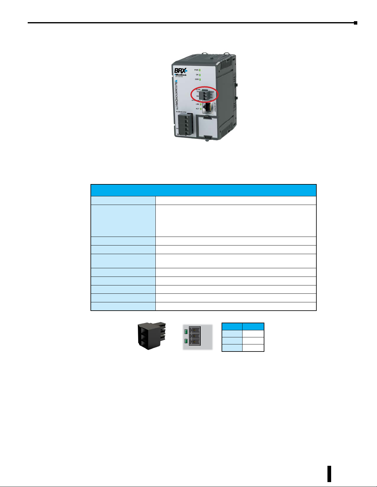
Modbus RTU, Serial Communications
Pinout RS485
1 GND
2 D-
3 D+
RS-485 is a multi-point wiring standard that can be used to connect external devices to the PLC. The
RS-485 port has a removable three-pin screw terminal block located on the front of the CPU. The serial port
has a software-selectable 120Ω termination resistor available if needed.
RS-485 Specifications
Port Type RS-485
Non-isolated serial port that can communicate via RS-485.
Description
Supported Protocols Modbus RTU (Slave)
Data Rates 1200, 2400, 4800, 9600, 19200, 38400, 57600, and 115200
Timeout
Default Settings RS-485, 115200 bps, No Parity, 8 Data Bits, 1 Stop Bit, Station #1
Port Type 3-pin terminal strip 3.5mm pitch
RS-485 Station Addresses 1-247
Cable Requirements RS-485 use L19954-XXX from AutomationDirect.com
Replacement Connector ADC Part # BX-RTB03S
Includes ESD protection and built-in surge protection.
120Ω Termination resistor is available (software selectable).
Includes internal biasing to be a true failsafe receiver while
maintaining EIA/TIA-485 compatibility.
Fixed at 800ms. Once the rst character arrives, the controller waits
800ms for the entire request to arrive.
Chapter 15: BX-MBIO Modbus I/O Controller
The RS-485 standard supports distances of up to 1000 meters without requiring a repeater. The distance can
be increased by placing an RS-485 repeater on the network, if necessary.
RS-485 utilizes a differential signal which makes it much more immune to noise and grounding issues than
RS-232 and is therefore a much better choice when available for communications. This port only supports
RS-485, 2-wire connections. Please note that there are no connections for RTS (Ready To Send), CTS (Clear
To Send) or for port powered devices (+5VDC).
BRX User Manual, 4th Edition, Rev. F
TX
GND
D-
RX
D+
RS485
Removable connector included (ADC Part# BX-RTB03S)
Pinout RS-485
1 GND
2 D3 D+
15-15
Page 16
Chapter 15: BX-MBIO Modbus I/O Controller
Modbus Client
Sig
O-M
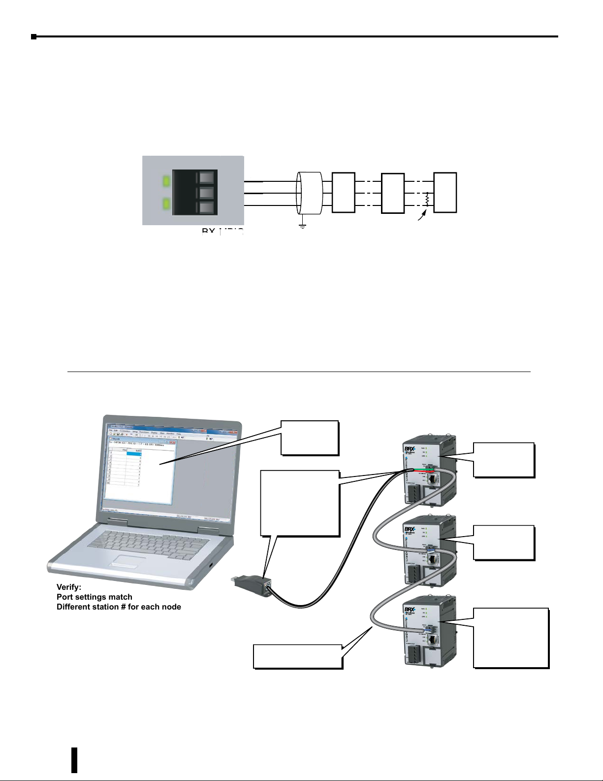
ADC # L19954-xxx or equivalent is recommend for RS-485 networks.
Modbus RTU, Serial Communications, continued
Field Wiring information:
RS-485*
RS-485
TX
RX
GND
D-
D+
BX-MBIO
Signal GND
n
D-
-
D+
Slave 1
GND
D-
D+
Slave n
GND
D-
D+
Field Device
Termination
User-supplied
GND
D-
D+
*NOTE: Termination resistor is built-in and software selectable.
RS-485 example wiring diagrams
Example Wiring BX-MBIO to PC via RS-485, using Modbus Poll Software as Modbus RTU Master
RS-485 Modbus RTU Network
Modbus RTU
Master Poll
Utility
AutomationDirect
Part # USB-485
Black 2-wire cable
(flying leads):
Red (to D+)
Green (to D-)
Modbus RTU
BX-MBIO-M
Node 1
Modbus RTU
BX-MBIO-M
Node 2
Verify:
Port settings match
Different station # for each node
Terminate on each end of network
when possible.
Recommend cable:
ADC P/N L19954-XXX
15-16
BRX User Manual, 4th Edition, Rev. F
Modbus RTU
BX-MBIO-M
Last Node
120Ω Termination
Enabled
(Software Selectable)
Page 17
Chapter 15: BX-MBIO Modbus I/O Controller
Modbus RTU, Serial Communications, continued
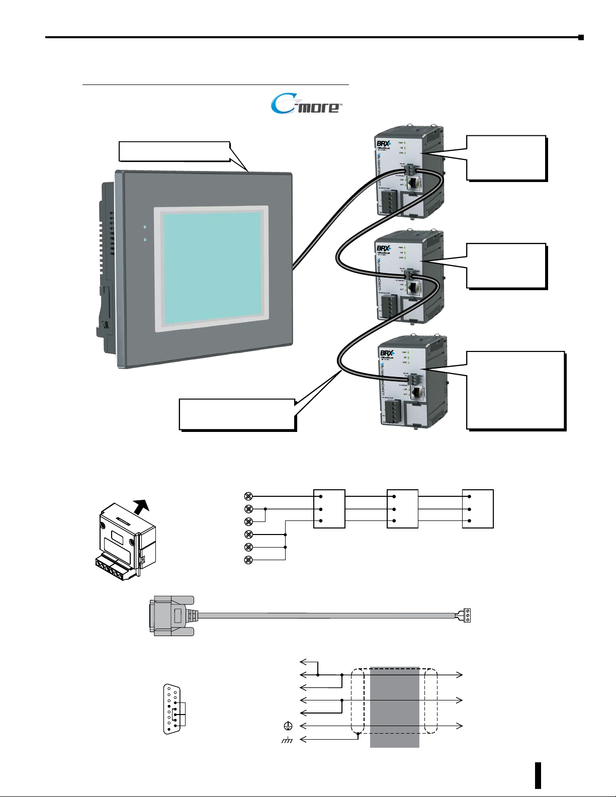
Example Wiring BX-MBIO to C-more HMI via RS-485
RS-485 C-more RTU Network
Modbus RTU Master
Recommend cable:
ADC P/N L19954-XXX
Modbus RTU
BX-MBIO-M
Node 1
Modbus RTU
BX-MBIO-M
Node 2
Modbus RTU
BX-MBIO-M
Last Node
120Ω Termination
Enabled
(Software Selectable)
EA-COMCON-3 (-3A)
Terminal Block Adapter
plugs into C-more 15-pin
PLC Serial Comm. Port
15-pin
D-sub
8 = do not use
7 = do not use
6 = do not use
5 = Logic GND
4 = do not use
3 = do not use
2 = do not use
1 = Frame GND
(male)
1
GND
RD –
SD –
SD +
RD +
TERM
15 = do not use
14 = do not use
15
13 = Termination
12 = SD– (RS485)
11 = SD+ (RS485)
10 = RD– (RS485)
9 = RD+ (RS485)
BX-MBIO-M
Node 1
GND
D-
D+
BX-MBIO-M
Node 2
GND
D-
D+
User-Constructed Cable
BX-MBIO-M (-D)
Term.
RD + D +
SD +
RD – D –
SD –
13
9
11
10
12
5
1
Wiring Diagram
shield
BX-MBIO-M
Last Node
GND
D-
D+
GND
BRX User Manual, 4th Edition, Rev. F
15-17
Page 18
Chapter 15: BX-MBIO Modbus I/O Controller
Modbus RTU, Serial Communications, continued
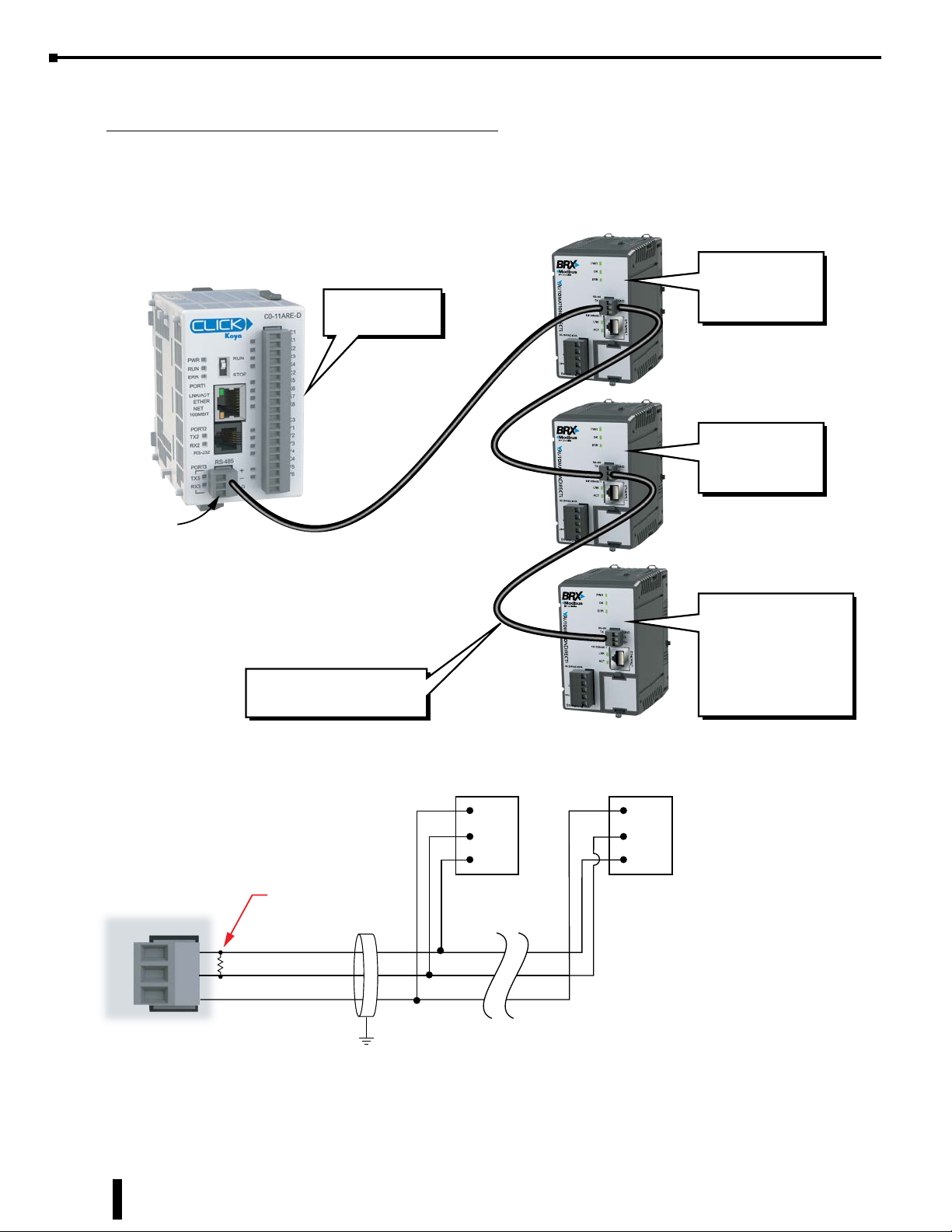
Example Wiring BX-MBIO to Click PLC via RS-485
RS-485 Click to BX-MBIO
Modbus RTU
Master
Modbus RTU
BX-MBIO-M
Node 1
Modbus RTU
BX-MBIO-M
Node 2
Port 3
+
–
LG
RS-485
Recommend cable:
ADC P/N L19954-XXX
User-supplied
120Ω Termination
(+)
(–)
GND
GND
D-
D+
Modbus RTU
BX-MBIO-M
Last Node
120Ω Termination
Enabled
(Software Selectable)
BX-MBIO-M (-D)BX-MBIO-M (-D)
GND
D-
D+
120Ω Termination
Enabled
(Software Selectable)
15-18
BRX User Manual, 4th Edition, Rev. F
Page 19
Chapter 15: BX-MBIO Modbus I/O Controller
Modbus RTU, Serial Communications, continued
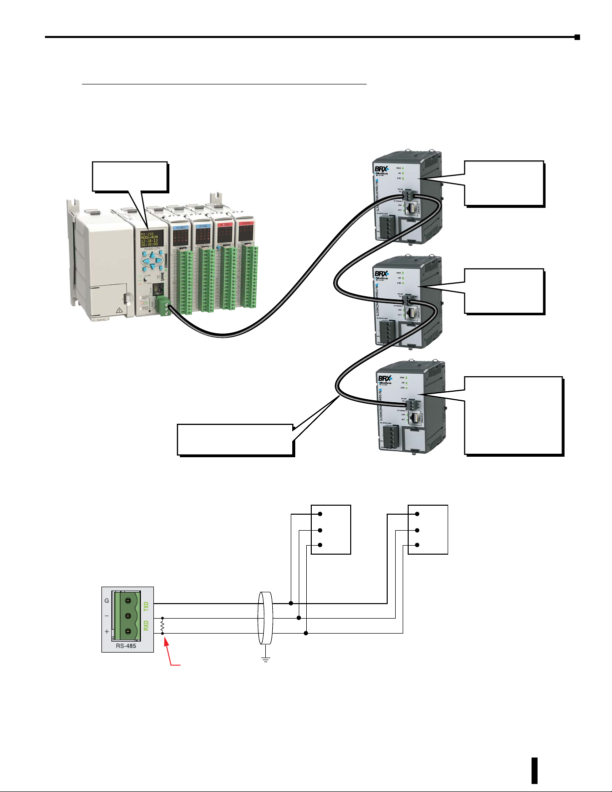
Example Wiring BX-MBIO to Productivity PLC via RS-485
RS-485 Productivity to BX-MBIO
Modbus RTU
Master
Recommend cable:
ADC P/N L19954-XXX
Modbus RTU
BX-MBIO-M
Node 1
Modbus RTU
BX-MBIO-M
Node 2
Modbus RTU
BX-MBIO-M
Last Node
120Ω Termination
Enabled
(Software Selectable)
Signal GND
TXD-/RXD-
TXD+/RXD+
User-supplied
120Ω Termination
BRX User Manual, 4th Edition, Rev. F
BX-MBIO-M (-D)
GND
D-
D+
BX-MBIO-M (-D)
GND
D-
D+
120Ω Termination
Enabled
(Software Selectable)
15-19
Page 20

Chapter 15: BX-MBIO Modbus I/O Controller
Modbus TCP, Ethernet Communications
The RJ-45 Ethernet port connector is located on the CPU faceplate. Rated at 10/100 Mbps, it accepts
standard CAT5e cable and has built-in auto-crossover capability.
Ethernet Specifications
Port Type Ethernet
Description Standard transformer-isolated Ethernet port with built-in surge protection.
Transfer Rate 10Mbps and 100Mbps
Port Status LED
Timeout
Supported Protocols Modbus TCP (Server)
Cable Recommendation C5E-STxxx-xx from AutomationDirect.com
Port Type RJ45, Category 5, 10/100 BASE-T, Auto Crossover
Ethernet Port Numbers:
Modbus TCP (Server)
LINK LED is solid when network LINK is established. ACT LED ashes
when port is active.
Fixed at 800ms. Once the rst character arrives, the controller waits
800ms for the entire request to arrive.
502, TCP
BX-MBIO Configuration
To perform the initial configuration of the BX-MBIO, use the NetEdit 3 utility. Please refer to Appendix
E of this manual for information on how the free NetEdit 3 utility is used to manage all aspects of HOST
Ethernet-enabled devices. This includes the configuration of the network settings, updating the firmware in
the devices, and setting up any runtime configuration options that are available to the HOST device.
Once the BX-MBIO has been assigned an IP address and subnet by using NetEdit 3, it is possible to use the
Web Configuration Page to perform additional configurations.
The Web Configuration Page can be accessed via NetEdit 3 or via a browser.
15-20
BRX User Manual, 4th Edition, Rev. F
Page 21
BX-MBIO Configuration, continued
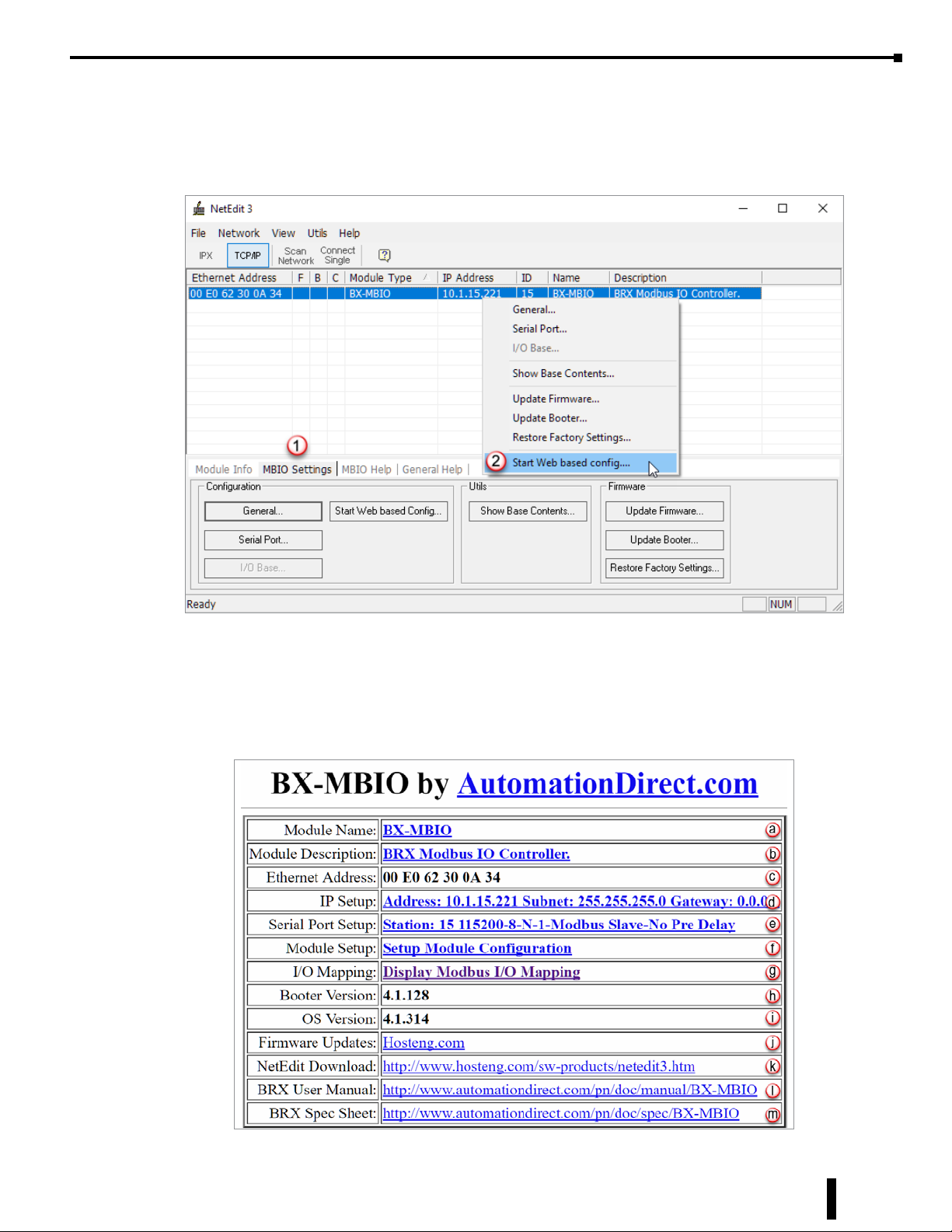
If using NetEdit 3, select BX-MBIO from the list of available HOST Ethernet devices. You can select the
“Start Web based Config” from the (1) MBIO Settings tab or from the (2) drop down list you get when you
right click on the BX-MBIO row.
Chapter 15: BX-MBIO Modbus I/O Controller
If using a web browser, enter the IP address of the BX-MBIO you want to configure in the URL address field
of the web browser.
After selecting “Start Web based Config…” in NetEdit 3 or accessing the IP address of the BX-MBIO via a
browser page, the following web page will open in your default Web Browser:
BRX User Manual, 4th Edition, Rev. F
15-21
Page 22
Chapter 15: BX-MBIO Modbus I/O Controller
BX-MBIO Configuration, continued
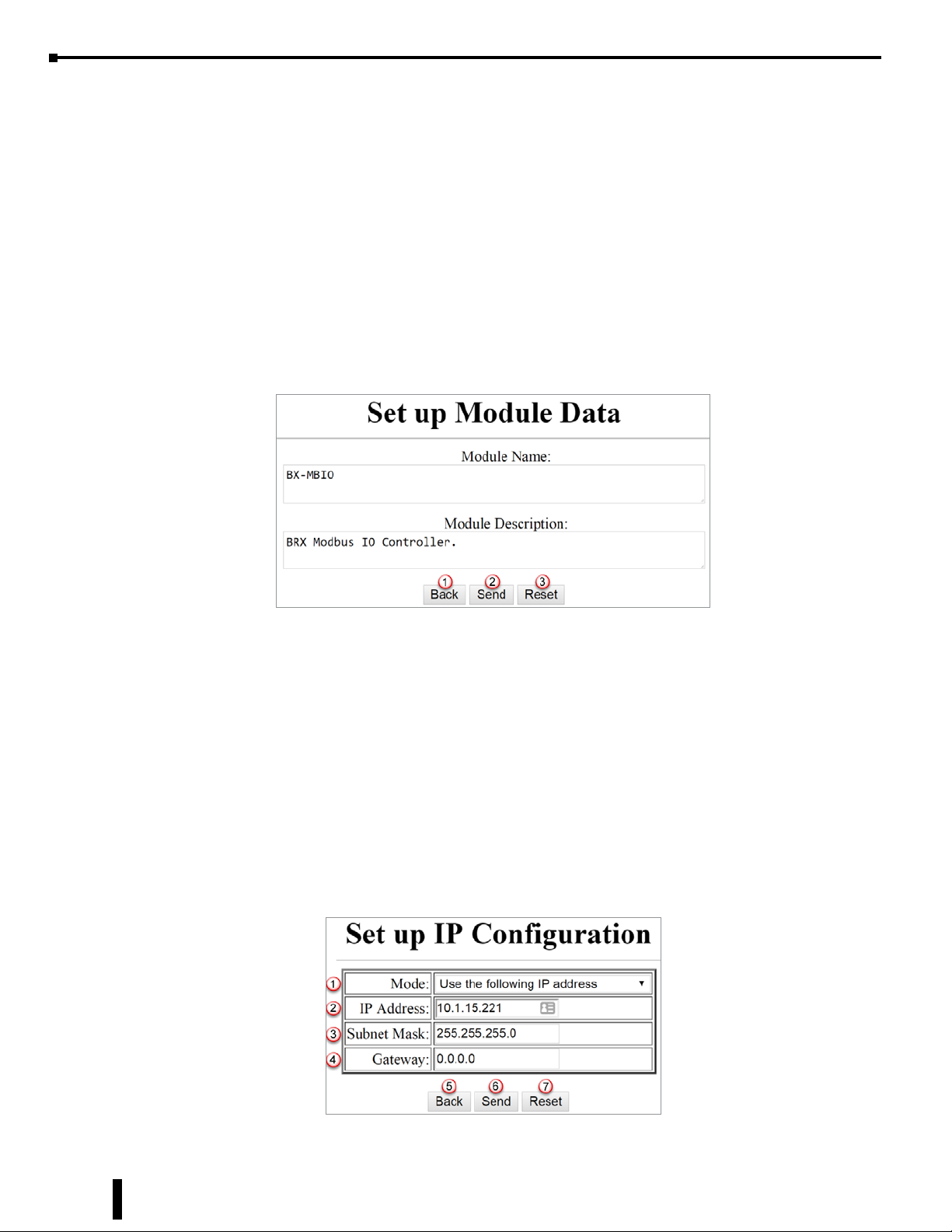
(a) Module Name
The user is able to change the name of the module, making it meaningful to the location or the
process. Select the (a) link to change the name. The Module Name can be 255 characters long.
(b) Module Description
The user is able to change the description of the module, allowing the addition of pertinent information
to the process. Select the (b) link to edit the module description. The Module Description can be
255 characters long.
Selecting the link to change the (a) Module Name or the (b) Module Description, brings up this
page:
(1) Back button, returns you to the main setup page of the Web configuration page.
(2) Send button, writes the modified information to the BX-MBIO.
(3) Reset button, changes any edits back to default.
To complete editing the Module Name or Description, select the (2) Send button. Once it is
complete, a dialog box will confirm “Module Data setup complete.”
(c) Ethernet Address
This field displays the MAC address of the BX-MBIO. This is a static field.
(d) IP Setup
The user is able to change the IP address, the subnet and the gateway of the module. Access the setup
page by selecting the (d) link. This brings up the Set up IP Configuration page:
15-22
BRX User Manual, 4th Edition, Rev. F
Page 23
BX-MBIO Configuration, continued
(1) Mode: gives you two options from a drop-down menu:
(i) Obtain an IP address automatically. Use only if DHCP server is available.
(ii) Use the following IP address
(3) IP Address: Enter the BX-MBIO network IP address. This should be in the same family as that
of the Modbus client.
(4) Subnet Mask: Enter the Subnet Mask associated with the network to which the BX-MBIO is
added.
(5) Gateway: Enter the IP address of the network gateway.
(6) Back button, returns you to the main setup page of the Web configuration page.
(7) Send button, writes the modified information to the BX-MBIO.
(8) Reset button, changes any edits back to default.
To complete editing the Set up IP Configuration, select the (6) Send button. Once it is complete, a
dialog box will confirm “Set up IP Configuration complete.”
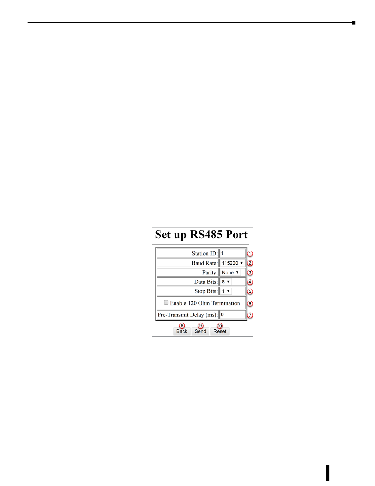
(e) Serial Port Setup
Chapter 15: BX-MBIO Modbus I/O Controller
Selecting the serial port setup link brings up the Set up RS485 Port page:
(1) Station ID: Enter a valid station number, 1-247. Each device on the network must have a unique
station ID.
(2) Baud Rate: The rate at which the data is transmitted. The higher the number the faster the
data will be transmitted. Choosing a lower value can help with issues when the data is not being
received reliably. Available Baud Rate choices: 115200, 57600, 38400, 19200, 9600, 4800, 2400,
1200. This must match the baud rate of the Modbus RTU master.
(3) Parity: The method of error detection used during transmission. Available choices: Even, Odd,
None.
(4) Data Bits: The number of bits in each character. Available choices: 7 or 8.
(5) Stop Bits: The number of bits sent to denote the end of each character. Available choices: 1 or 2.
BRX User Manual, 4th Edition, Rev. F
15-23
Page 24
Chapter 15: BX-MBIO Modbus I/O Controller
BX-MBIO Configuration, continued
(6) Enable 120-ohm Termination: When enabled, a 120-ohm termination resistor is added to the
BX-MBIO RS-485 circuit. Use only at the beginning and end of the RS-485 network.
(7) Pre-Transmit Delay (ms): Enter a time from 0 to 500ms. This allows the user to adjust the
response rate based on what master is talking to it. For example, a radio may require a delay
before they are ready to “receive” a packet of information.
(8) Back button, returns you to the main setup page of the Web configuration page.
(9) Send button, writes the modified information to the BX-MBIO.
(10) Reset button, changes any edits back to default.
(11) To complete editing the Serial Port Setup, select the (9) Send button. Once it is complete, a
dialog box will confirm “Serial Port Setup complete.”
(f) Module Setup
The user is able to view which expansion modules are in each slot. If Analog I/O modules are
installed, the user will be able to change the module configuration. Access the setup page by selecting
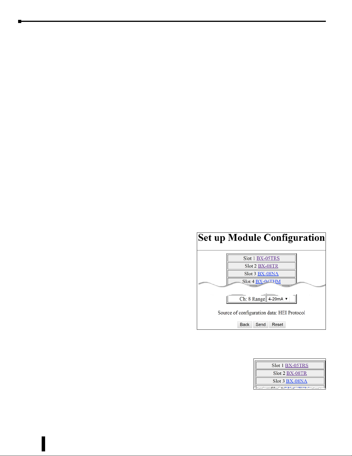
the (f) link. This brings up the Set up Module Configuration page. In general, the page will display
a list of slot numbers and the module part number installed in that slot. Configuration fields will be
available for the slot with an installed Analog I/O module.
Each displayed module part number is a hyperlink to the product insert for that module on www.
AutomationDirect.com.
One example configuration used to illustrate the module setup interface comprises the following:
Slot 1: BX-05TRS
Slot 2: BX-08TR
Slot 3: BX-08NA
Slot 4: BX-04THM
Slot 5: BX-08AD-2B
Slot 6: BX-08DA-2B
Slot 7: BX-08AD-1
Slot 8: BX-08DA-1
We will step through the Set up Module Configuration page for this example slot-by-slot.
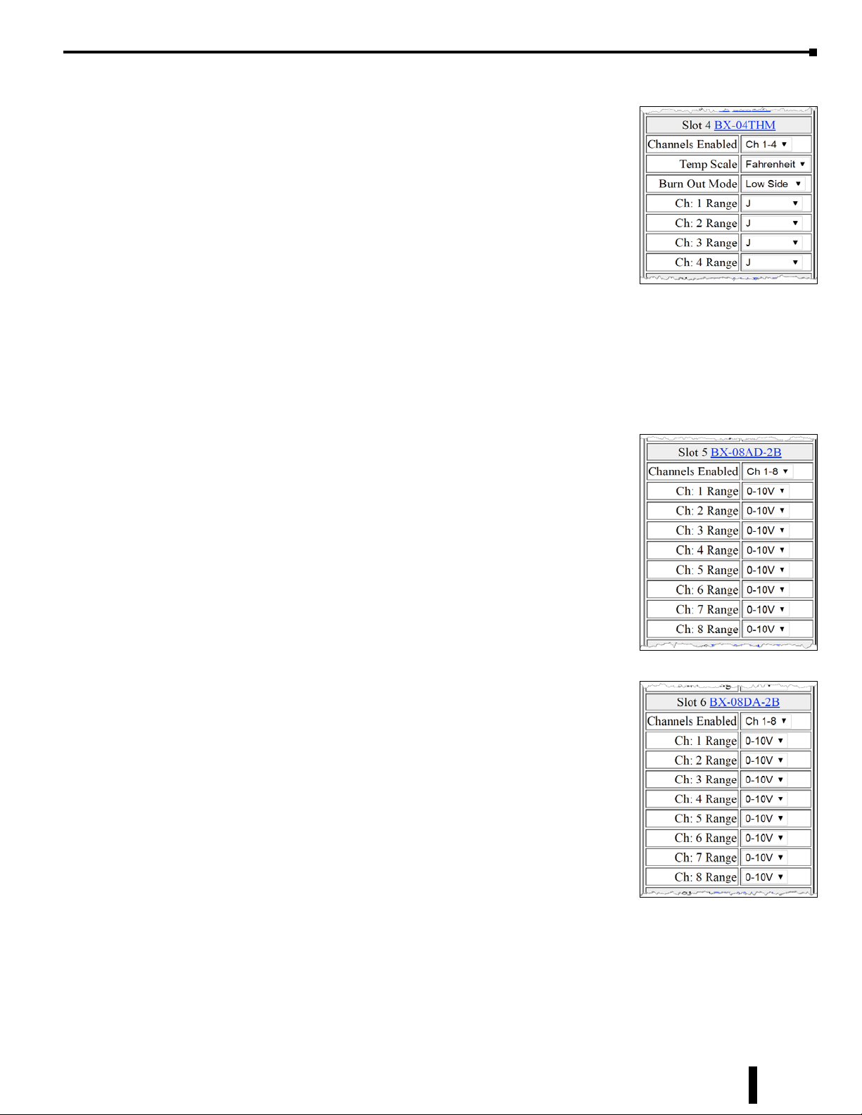
Slots 1–3 (Discrete I/O modules):
15-24
In this example we have three discrete I/O modules installed. There
is nothing to configure for these discrete I/O modules. All Discrete
I/O expansion modules available to the BRX series work in a similar
manner.
BRX User Manual, 4th Edition, Rev. F
Page 25
BX-MBIO Configuration, continued
Slot 4 (BX-04THM):
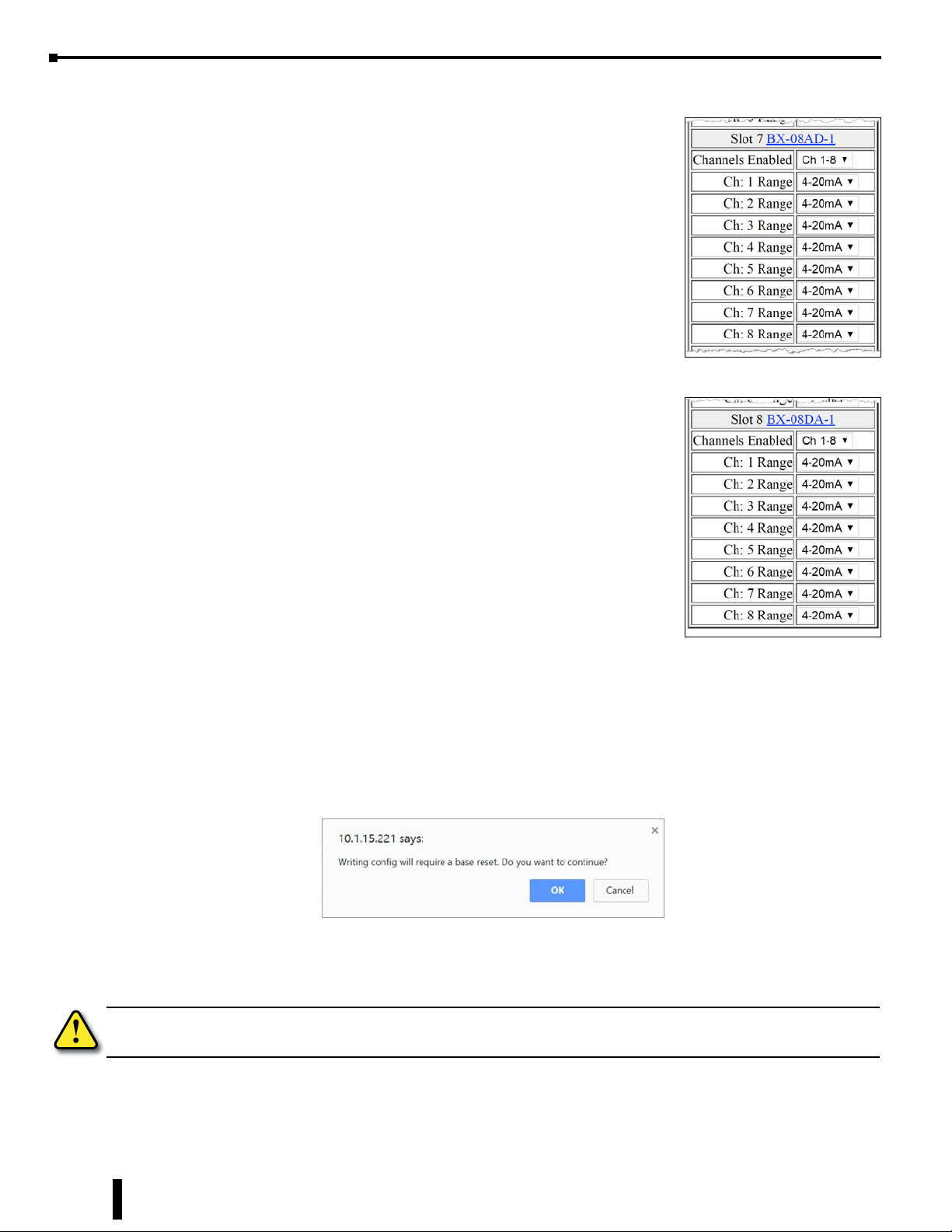
The BX-04THM analog temperature module is installed in slot
4 in this example. The BX-04THM module has the following
configuration options:
(i) Channels Enabled: (1–4)
(ii) Temp Scale: Celsius or Fahrenheit.
(iii) Burn Out Mode: Select if the Input register should read a Low
or High value on burn out or if burn out detection should be
disabled. Note: Burn Out Mode must be set to Disabled in
order to use a Thermocouple Calibrator.
(iv) Input Range for Channels 1 to 4: These are the settings for each channel of the analog
temperature module. Available choices are: J, K, E, R, S, T, B, N, C, 0-39mV, +/-39mV,
+/-78mV, 0-156mV, +/-156mV, 0-1.25V.
Slot 5 (BX-08AD-2B):
Chapter 15: BX-MBIO Modbus I/O Controller
The BX-08AD-2B is installed in slot 5 in this example. The
BX-08AD-2B module has the following configuration options:
(i) Channels Enabled: (1–8)
(ii) Range for Input Channels 1 to 8: There is a configuration field
for each channel. Available choices are: 0-5V, 0-10V, +/-5V,
+/-10V.
Slot 6 (BX-08DA-2B):
The BX-08DA-2B is installed in slot 6 of this example. The
BX-08DA-2B module has the following configuration options:
(i) Channels Enabled: (1–8)
(ii) Range for Output Channels 1 to 8: There is a configuration
field for each channel. Available choices are: 0–5V, 0–10V,
±5V, ±10V.
BRX User Manual, 4th Edition, Rev. F
15-25
Page 26
Chapter 15: BX-MBIO Modbus I/O Controller
BX-MBIO Configuration, continued
Slot 7 (BX-08AD-1):
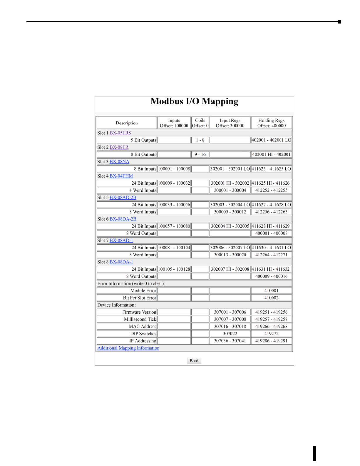
The BX-08AD-1 is installed in slot 7 of this example. The
BX-08AD-1 module has the following configuration options:
(i) Channels Enabled: (1–8)
(ii) Range for Input Channels 1 to 8: There is a configuration field
for each channel. Available choices are: 0–20mA, 4–20mA.
Slot 8 (BX-08DA-1):
The BX-08DA-1 is installed in slot 8 of the sample drop. The
BX-08DA-1 module has the following configuration options:
(i) Channels Enabled: (1–8)
(ii) Range for Output Channels 1 to 8: There is a configuration
field for each channel. Available choices are: 0–20mA,
4–20mA.
The Back button returns you to the main setup page of the Web configuration page, the Send button
writes the modified information to the BX-MBIO, and the Reset button changes any edits back to
default.
To complete editing the Setup Module Configuration, select the Send button. The BX-MBIO will
be rebooted in order to use the new configuration. A warning and confirmation message box will be
displayed:
If you press the OK button, the new configuration will be written to the BX-MBIO.
15-26
WARNING: Output states are not retained when a new configuration is written to the BX-MBIO. Only authorized
persons should write a configuration.
Once the write is complete, a dialog box will confirm “Setup complete.”
BRX User Manual, 4th Edition, Rev. F
Page 27
BX-MBIO Configuration, continued
(g) I/O Mapping
The Modbus I/O Mapping page is viewable by selecting the (g) link. This page displays the Modbus
I/O addressing associated with each slot plus error and device information.
Based on the example set of installed modules listed previously, the following Modbus I/O Mapping
table is displayed.
Chapter 15: BX-MBIO Modbus I/O Controller
Description column:
Displays the slot number, the module installed in that slot and the Input/Output bits and/or words
used by the module. The module part number is a link to the module insert.
BRX User Manual, 4th Edition, Rev. F
15-27
Page 28

Chapter 15: BX-MBIO Modbus I/O Controller
BX-MBIO Configuration, continued
Inputs column:
Displays the discrete input addressing. The offset is 100000. If a module has discrete input addresses
associated with it, the Modbus discrete input address range is shown. For example, in slot 3, the
BX-08NA module is mapped to 8 discrete input addresses, 100001 – 100008.
Coils column:
Displays the discrete output addressing. The offset is 0. If a module has discrete output addresses
associated with it, the Modbus discrete output range is shown. For example, in slot 1, the BX-05TRS
module is mapped to 5 discrete output addresses. However, the addressing is mapped in byte ranges,
which means the module takes up 8 bits, 1 – 8. For this module, BX-05TRS, the user will use the
first 5 bits of the addressed range, 1-5.
Input Regs column:
Displays the input register addressing. The offset is 300000. If a module has input registers associated
with it, the Modbus input register range is shown. Input registers are typically used to store analog
input values. Input registers are typically read only registers. For example, in slot 4, the BX-04THM
module is mapped to 24 discrete input bits and 4 input words. These 4 words are mapped to 4 input
registers, 300001 – 300004, one word for each input channel. In this case, data read from channel
1 of the BX-04THM is stored in Modbus input register 300001.
Discrete inputs are also mapped to input registers. For example BX-08NA, an 8-point input module,
mapped to 302001 LO. This is the lower 8 bits of the 16-bit word 302001.
Analog and Temperature modules have 24 discrete inputs used as error status flags. These are also
mapped to input registers. For example, BX-04THM has 24 discrete input bits mapped to 302001
HI to 302002 input registers. This is the top 8 bits of 302001 and 16 bits of 302002.
Refer to Chapter 8, “BRX Analog I/O Expansion Modules,” for information on the function of the
24 bits associated with Analog I/O and Temperature modules.
Holding Regs column:
Displays the holding register addressing. The offset is 400000. If a module has holding registers
associated with it, the Modbus holding register range is shown. Holding registers are typically used to
store analog output values or to store variable data used by the system. Holding registers are typically
read/write registers. For example, in slot 6, the BX-08DA-2B module is mapped to 24 discrete input
bits and 8 output words. These 8 words are mapped to 8 holding registers, 400001 – 400008, one
word for each output channel. In this case, data written to channel 1 of the BX-08DA-2B is stored
in Modbus holding register 400001.
Discrete inputs are also mapped to holding registers. For example BX-08NA, an 8-point input
module, mapped to 411625 LO. This is the lower 8 bits of the 16-bit word 411625.
15-28
Analog and Temperature modules have 24 discrete inputs used as error status flags. These are also
mapped to holding registers. For example, BX-04THM has 24 discrete input bits mapped to 411625
HI to 411626 holding registers. This is the top 8 bits of 411625 and 16 bits of 411626.
Refer to Chapter 8, “BRX Analog I/O Expansion Modules,” for information on the function of the
24 bits associated with Analog I/O and Temperature modules.
BRX User Manual, 4th Edition, Rev. F
Page 29
BX-MBIO Configuration, continued
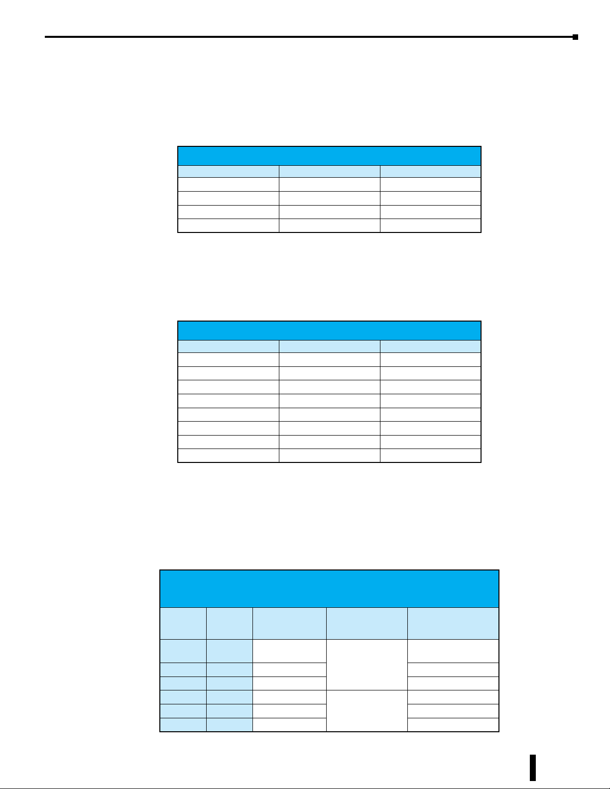
Extra information available in the Modbus I/O mapping table:
Addressing of available error information is mapped to holding registers. Module Error and Bit Per
Slot Error can be read from holding registers 410001 and 410002, for this setup. To clear an error,
write a value of 0 to the corresponding holding register.
BX-MBIO Diagnostic Information (write 0 to clear):
Data Input Registers Holding Registers
Module Error 410001
Bit Per Slot Error 410002
Reserved* 410003 – 410006
Link Monitor Timeout 410007
* This section is for use by the MBIO operating system. Do not write to this area.
Device Information is comprised of a block of 40 words. A Modbus client (master) can read the
entire block or a specific portion.
Chapter 15: BX-MBIO Modbus I/O Controller
BX-MBIO Device Information
Data Input Registers Holding Registers
Firmware Version 307001 – 307006 419251 – 419256
Millisecond Tick 307007 – 307008 419257 – 419258
Reserved* 307009 – 307015 419259 – 419265
MAC Address 307016 – 307018 419266 – 419268
Reserved* 307019 – 307022 419269 – 419271
DIP Switches 307022 419272
Reserved* 307023 – 307035 419273 – 419285
IP Addressing 307036 – 307041 419286 – 419291
* This section is for use by the MBIO operating system. Do not write to this area.
The Device Information displays items from those available in the table above. These are as follows:
(1) Firmware Version: six words hold information on the Firmware and Booter version of the
BX-MBIO, mapped to input registers 307001-307006 and to holding registers 419251-419256.
BX-MBIO Firmware and Booter versions:
Firmware: 4.1.299 Booter: 4.1.128
Modbus
Input
Register
307001 419251 4
307002 419252 1
307003 419253 299 most signicant word
307004 419254 4
307005 419255 1
307006 419256 128 most signicant word
Modbus
Holding
Register
MAC address
value viewed as
Signed Decimal
least signicant word
Hold the
Firmware version
least signicant word
Hold the
Booter version
BRX User Manual, 4th Edition, Rev. F
15-29
Page 30
Chapter 15: BX-MBIO Modbus I/O Controller
BX-MBIO Configuration, continued
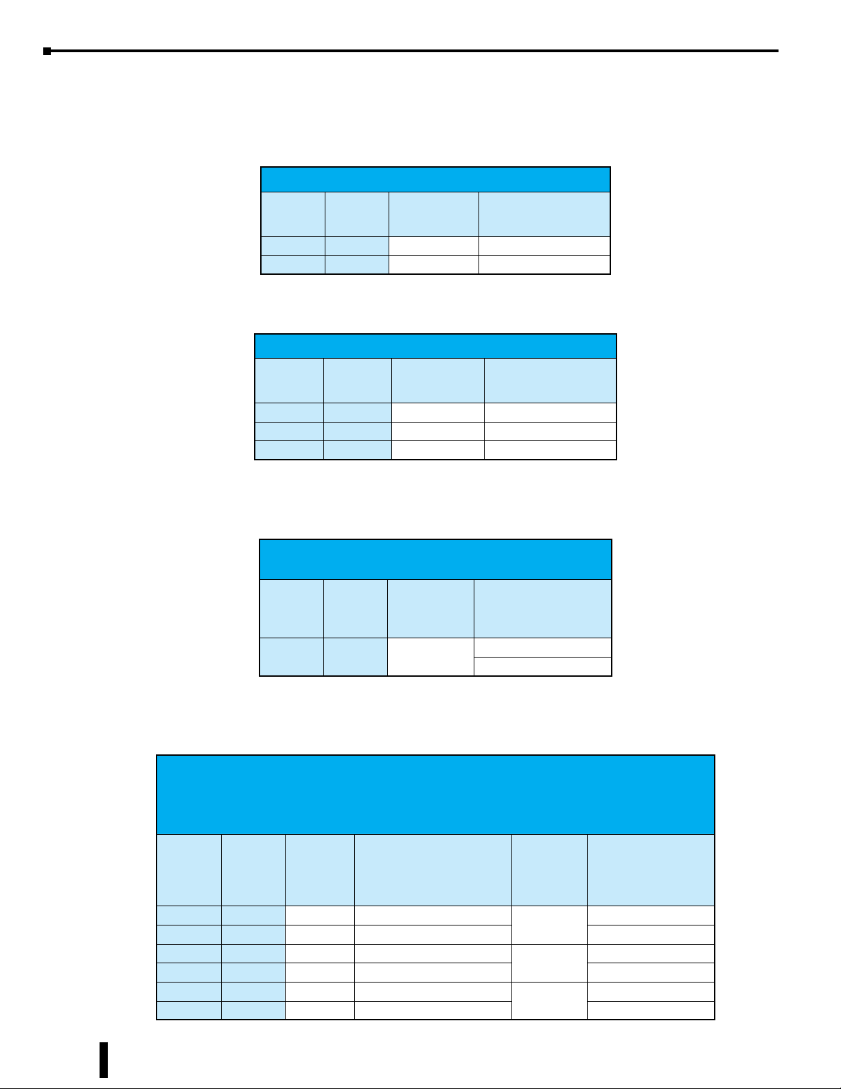
(2) Millisecond Tick: Two words hold information on the Millisecond Tick clock of the BX-MBIO,
which could be used to indicate communications is active with the BX-MBIO, mapped to input
registers 307007-307008 and to holding registers 419257-419258.
BX-MBIO Millisecond Tick
Modbus
Input
Register
307007 419257 0xE000 least signicant word
307008 419258 0x3062 most signicant word
(3) MAC Address: Three words hold information on the MAC address of the BX-MBIO, mapped
to input registers 307016-307018 and to holding registers 41 9266-419268.
BX-MBIO MAC address: 00:E0:62:30:0A:34
Modbus
Input
Register
307016 419266 0xE000 least signicant word
307017 419267 0x3062
307018 419268 0x340A most signicant word
Modbus
Holding
Register
Modbus
Holding
Register
MAC address
value viewed
as HEX
MAC address
value viewed
as HEX
(4) DIP Switches: One word holds information about the position of the DIP Switches of the
BX-MBIO, which provides the status of the DIP switch position, mapped to input register
307022 and holding register 419272.
BX-MBIO DIP Switch: Example with DIP
Switches 0 to 3 ON, serial port Station # 15
Modbus
Input
Register
307022 419272
Modbus
Holding
Register
(5) IP Addressing: Six words hold information about the IP address, the Gateway address, and
the Subnet mask of the BX-MBIO, mapped to input registers 307036-307041 and to holding
registers 419286-419291.
DIP Switch
value viewed
as Unsigned
Decimal
15
DIP Switch value
viewed in Binary
0000 0000 0000 1111
msb -------------------lsb
BX-MBIO IP and Subnet address:
IP: 10.1.15.221
Gateway: 192.168.2.1
Subnet: 255.255.255.0
MAC
Modbus
Input
Register
307036 419286 0x010A where: 01 = 1, 0A = 10
307037 419287 0xDD0F where: DD = 221, 0F = 15 most signicant word
307038 419288 0xA8C0 where: A8 = 168, C0 = 192
307039 419289 0x0102 where: 01 = 1, 02 = 2 most signicant word
307040 419290 0xFFFF where: FF = 255, FF = 255
307041 419291 0x00FF where: 00 = 0, FF = 255 most signicant word
Modbus
Holding
Register
address
value
viewed in
HEX
IP Address
Gateway
address
Subnet
mask
least signicant word
least signicant word
least signicant word
15-30
BRX User Manual, 4th Edition, Rev. F
Page 31
UPDATED
BX-MBIO Configuration, continued
(h) Booter Version
This field displays the current booter version of the BX-MBIO controller. This is a fixed field. It is
necessary to use the NetEdit 3 utility to update the booter.
(i) OS Version
This field displays the current OS version of the BX-MBIO controller. This is a fixed field. It is
necessary to use the NetEdit 3 utility to update the OS.
(j) Firmware Updates
This field contains a link to the firmware download location on the HOST Engineering website:
Hosteng.com (http://www.hosteng.com/hw-products/firmware.htm).
(k) NetEdit Download
This field contains a link to the NetEdit 3 utility download page: http://www.hosteng.com/
sw-products/netedit3.htm.
(l) BRX User Manual
This field contains a link to the BRX user manual web page: http://www.automationdirect.com/pn/
doc/manual/BX-MBIO.
Chapter 15: BX-MBIO Modbus I/O Controller
(m) BRX Spec Sheet
This field contains a link to the BX-MBIO-M insert page: http://www.automationdirect.com/pn/
doc/spec/BX-MBIO.
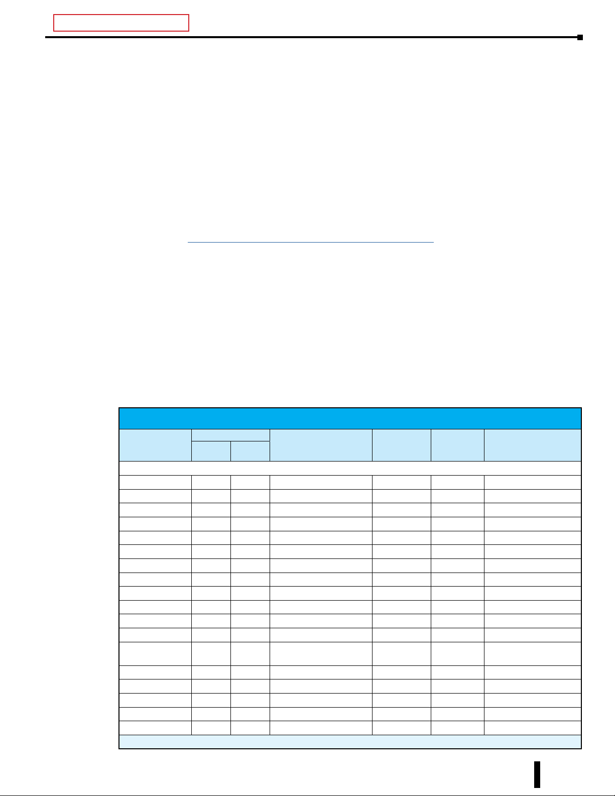
List of modules supported by BX-MBIO
Number of Points
Module
Discrete IO
BX-08NF3 8 1–8 1 02 100001–100008
BX-08ND3 8 1–8 1 02 100001–100008
BX-08NB 8 1–8 1 02 100001–100008
BX-08NA 8 1–8 1 02 100001–100008
BX-08SIM 8 1–8 1 02 100001–100008
BX-12ND3 12 1–12
BX-12NB 12 1–12
BX-12NA 12 1–12
BX-16NF3 16 1–16 2 02 100001–100016
BX-16ND3 16 1–16 2 02 100001–100016
BX-16NB 16 1–16 2 02 100001–100016
BX-16NA 16 1–16 2 02 100001–100016
BX-32ND3 32 1–16, 17–32 4 02
BX-05TRS 5 1–5
BX-05TRS-1 5 1–5
BX-08TD1 8 1–8 1 01, 05, 15 000001–000008
BX-08TD2 8 1–8 1 01, 05, 15 000001–000008
BX-08TR 8 1–8 1 01, 05, 15 000001–000008
Table continued on next page
In Out
Address Offset Bytes Used
1
1
1
2
2
2 02 100001–100016
2 02 100001–100016
2 02 100001–100016
1 01, 05, 15 000001–000008
1 01, 05, 15 000001–000008
Function
Codes
Example Addressing:
Module Installed in
Slot 1
100001–100016
100017–100032
1
1
1
2
2
BRX User Manual, 4th Edition, Rev. F
15-31
Page 32

Chapter 15: BX-MBIO Modbus I/O Controller
BX-MBIO Configuration, continued
List of modules supported by BX-MBIO (continued)
Number of Points
Module
BX-08TRZ 8 1–8 1 01, 05, 15 000001–000008
BX-08TA 8 1–8 1 01, 05, 15 000001–000008
BX-12TD1 12 1–12
BX-12TD2 12 1–12
BX-12TR 12 1–12
BX-12TA 12 1–12
BX-16TD1 16 1–16 2 01, 05, 15 000001–000016
BX-16TD2 16 1–16 2 01, 05, 15 000001–000016
BX-16TF2 16 1–16 2 01, 05, 15 000001–000016
BX-16TR 16 1–16 2 01, 05, 15 000001–000016
BX-16TRZ 16 1–16 2 01, 05, 15 000001–000016
BX-32TD1 32 1–16, 17–32 4 01, 05, 15
BX-32TD2 32 1–16, 17–32 4 01, 05, 15
BX-08CD3R 4 4
BX-12CD3D1 8 4
BX-12CD3D2 8 4
BX-16CD3D1 8 8
BX-16CD3D2 8 8
BX-12CF3F2 8 8
Analog IO
BX-04ADM-1 4
BX-04AD-1 4
BX-08AD-1 8
BX-16AD-1 16
BX-04AD-2B 4
BX-08AD-2B 8
BX-16AD-2B 16
BX-04AD-3 4
BX-08AD-3 8
BX-04DA-1 4
Table continued on next page
In Out
Address Offset Bytes Used
1
1
1
1
Input: 1–43
Output: 1–4
Input: 1–8
Output: 1–4
Input: 1–8
Output: 1–4
Input: 1–8
Output: 1–8
Input: 1–8
Output: 1–8
Input: 1–8
Output: 1–8
Data Words: 1–4
Status Flags4: 1–24
Data Words: 1–4
Status Flags4: 1–24
Data Words: 1–8
Status Flags4: 1–24
Data Words: 1–16
Status Flags4: 1–24
Data Words: 1–4
Status Flags4: 1–24
Data Words: 1–8
Status Flags4: 1–24
Data Words: 1–16
Status Flags4: 1–24
Data Words: 1–4
Status Flags: 1–8
Data Words: 1–8
Status Flags: 1–8
Data Words: 1–4
Status Flags4: 1–24
UPDATED
Function
Codes
2 01, 05, 15 000001–000016
2 01, 05, 15 000001–000016
2 01, 05, 15 000001–000016
2 01, 05, 15 000001–000016
3
3
3
1
1
1
1
1
1
1
1
1
1
1
1
2 (per word) 304
2 (per word) 304
2 (per word) 304
2 (per word) 304
2 (per word) 304
2 (per word) 304
2 (per word) 304
2 (per word) 104
2 (per word) 104
2 (per word) 303, 06, 16 02400001–400004
02
01, 05, 15
02
01, 05, 15
02
01, 05, 15
02
01, 05, 15
02
01, 05, 15
02
01, 05, 15
02
02
02
02
02
02
02
02
02
Example Addressing:
Module Installed in
Slot 1
1
1
1
1
100001–100016
100017–100032
100001–100016
100017–100032
100001–1000083
000001–000008
100001–100008
000001–000008
100001–100008
000001–000008
100001–100008
000001–000008
100001–100008
000001–000008
100001–100008
000001–000008
300001–300004
100001–100024
300001–300004
100001–100024
300001–300008
100001–100024
300001–300016
100001–100024
300001–300004
100001–100024
300001–300008
100001–100024
300001–300016
100001–100024
300001–300004
100001–100008
300001–300008
100001–100008
100001–100024
3
3
3
15-32
BRX User Manual, 4th Edition, Rev. F
Page 33

BX-MBIO Configuration, continued
List of modules supported by BX-MBIO (continued)
Number of Points
Module
BX-08DA-1 8
BX-04DA-2B 4
BX-08DA-2B 8
BX-04DA-3 4
BX-08DA-3 8
BX-2AD2DA-1 2 2
BX-4AD2DA-1 4 2
BX-2AD2DA-2B 2 2
BX-4AD2DA-2B 4 2
BX-2AD2DA-3 2 2
BX-4AD4DA-3 4 4
Temperature
BX-04THM 4
BX-08THM 8
BX-06RTD 6
BX-04UT 4
BX-08UT 8
BX-08NTC 8
Table continued on next page
In Out
Address Offset Bytes Used
Data Words: 1–8
Status Flags4: 1–24
Data Words: 1–4
Status Flags4: 1–24
Data Words: 1–8
Status Flags4: 1–24
Data Words: 1–4
Status Flags: 1–8
Data Words: 1–8
Status Flags: 1–8
Input Data Words: 1–2
Output Data Words: 1–2
Status Flags4: 1–24
Input Data Words: 1–4
Output Data Words: 1–2
Status Flags4: 1–24
Input Data Words: 1–2
Output Data Words: 1–2
Status Flags4: 1–24
Input Data Words: 1–4
Output Data Words: 1–2
Status Flags4: 1–24
Input Data Words: 1–2
Output Data Words: 1–2
Status Flags: 1–8
Input Data Words: 1–4
Output Data Words: 1–4
Status Flags: 1–8
Data Words: 1–4
Status Flags (Bits)4: 1–24
Data Words: 1–8
Status Flags (Bits)4: 1–24
Data Words: 1–6
Status Flags (Bits)4: 1–24
Data Words: 1–4
Status Flags (Bits): 1–16
Data Words: 1–8
Status Flags (Bits): 1–16
Data Words: 1–8
Status Flags (Bits)4: 1–24
Chapter 15: BX-MBIO Modbus I/O Controller
Function
Codes
2 (per word) 303, 06, 16 02400001–400008
2 (per word) 303, 06, 16 02400001–400004
2 (per word) 303, 06, 16 02400001–400008
2 (per word) 103, 06, 16 02400001–400004
2 (per word) 103, 06, 16 02400001–400008
2 (per word)
2 (per word)
3
2 (per word)
2 (per word)
3
2 (per word)
2 (per word)
3
2 (per word)
2 (per word)
3
2 (per word)
2 (per word)
1
2 (per word)
2 (per word)
1
2 (per word) 304
2 (per word) 304
2 (per word) 304
2 (per word) 204
2 (per word) 204
2 (per word) 304
04
03, 06, 16
02
04
03, 06, 16
02
04
03, 06, 16
02
04
03, 06, 16
02
04
03, 06, 16
02
04
03, 06, 16
02
02
02
02
02
02
02
Example Addressing:
Module Installed in
Slot 1
100001–100024
100001–100024
100001–100024
100001–100008
100001–100008
300001–300002
400001–400002
100001–100024
300001–300004
400001–400002
100001–100024
300001–300002
400001–400002
100001–100024
300001–300004
400001–400002
100001–100024
300001–300002
400001–400002
100001–100008
300001–300004
400001–400002
100001–100008
300001–300004
100001–100024
300001–300008
100001–100024
300001–300006
100001–100024
300001–300004
100001–100016
300001–300008
100001–100016
300001–300008
100001–100024
BRX User Manual, 4th Edition, Rev. F
15-33
Page 34

Chapter 15: BX-MBIO Modbus I/O Controller
BX-MBIO Configuration, continued
List of modules supported by BX-MBIO (continued)
Number of Points
Module
BX-4RTD4DA-1 4 4
BX-4THM4DA-1 4 4
BX-4UT4DA-3 4 4
BX-4UT4TD1 4 4
BX-4UT4TD2 4 4
BX-4UT4TR 4 4
1. The 12-point modules use 12 addressing bits, but they are mapped to 16 bits (two bytes). Addressing follows a Byte
boundary.
2. The 5-point module uses 5 addressing bits, mapped to 8 bits (one byte). Addressing follows a Byte boundary.
3. The 8- and 12-point combo modules with four input or four output points use 4 addressing bits, but are mapped to 8 bits
(one byte). Addressing follows a Byte boundary.
4. Module uses 24 bits as Status Flags. These are mapped to 24 addressing bits (3 bytes). Addressing follows a Byte boundary.
In Out
Address Offset Bytes Used
Input Data Words: 1–4
Output Data Words: 1–4
Status Flags (Bits)4: 1–24
Input Data Words: 1–4
Output Data Words: 1–4
Status Flags (Bits)4: 1–24
Input Data Words: 1–4
Output Data Words: 1–4
Status Flags: 1–8
Input Data Words: 1–4
Output Data Words: 1–4
Status Flags: 1–8
Input Data Words: 1–4
Output Data Words: 1–4
Status Flags: 1–8
Input Data Words: 1–4
Output Data Words: 1–4
Status Flags: 1–8
2 (per word)
2 (per word)
3
2 (per word)
2 (per word)
3
2 (per word)
2 (per word)
1
2 (per word)
2 (per word)
1
2 (per word)
2 (per word)
1
2 (per word)
2 (per word)
1
Function
Codes
04
03, 06, 16
02
04
03, 06, 16
02
04
03, 06, 16
02
04
03, 06, 16
02
04
03, 06, 16
02
04
03, 06, 16
02
Example Addressing:
Module Installed in
Slot 1
300001–300004
400001–400002
100001–100024
300001–300004
400001–400002
100001–100024
300001–300004
400001–400002
100001–100008
300001–300004
400001–400002
100001–100008
300001–300004
400001–400002
100001–100008
300001–300004
400001–400002
100001–100008
Troubleshooting with Modbus Poll
Detailed Example: Using the Modbus Poll Utility to Verify Communications With BX-MBIO
This example explains how to use the Modbus client utility, Modbus Poll, to establish communications with
a BX-MBIO Modbus server (slave) and read and write information related to the discrete and analog I/O
modules connected to the BX-MBIO.
For this test, the following hardware will be used:
• Slot 0: BX-MBIO-M
• Slot 1: BX-05TRS
• Slot 2: BX-08TR
• Slot 3: BX-08NA
• Slot 4: BX-04THM
• Slot 5: BX-08AD-2B
• Slot 6: BX-08DA-2B
• Slot 7: BX-08AD-1
• Slot 8: BX-08DA-1
15-34
BRX User Manual, 4th Edition, Rev. F
Page 35
Chapter 15: BX-MBIO Modbus I/O Controller
Troubleshooting with Modbus Poll, continued
Start by wiring the modules to provide live data for the test:
1. Wire the BX-08TR to the BX-08NA. When an output point is turned on, the corresponding input
will turn on.
2. Wire the BX-08AD-2B to the BX-08DA-2B and wire the BX-08AD-1 to the BX-08DA-1. When
a value is written to an analog output channel, the corresponding input channel should read a value
that is approximately the same as the output value. For example, if a value of 32750 is written to
BX-08DA-1, we would expect the BX-08AD-1 to read a value of 32750 or very close to it. Note that
the values may not be identical due to the nature of analog I/O.
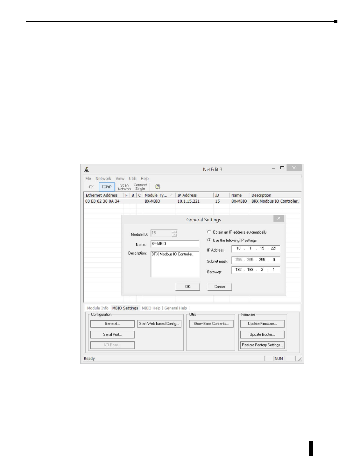
Connect the BX-MBIO to the same network switch as the PC running the Modbus Poll utility. It is also
possible to connect a PC Ethernet port directly to the BX-MBIO. Apply power to the unit.
Open the NetEdit 3 utility and select the BX-MBIO on the list. Under the MBIO Settings table, click on
the General button to configure the IP address and the subnet mask:
From the example above, the test BX-MBIO is configured with IP address of 10.1.15.221 and a subnet mask
of 255.255.255.0. If needed, a Gateway address can be configured here.
BRX User Manual, 4th Edition, Rev. F
15-35
Page 36
Chapter 15: BX-MBIO Modbus I/O Controller
Troubleshooting with Modbus Poll, continued
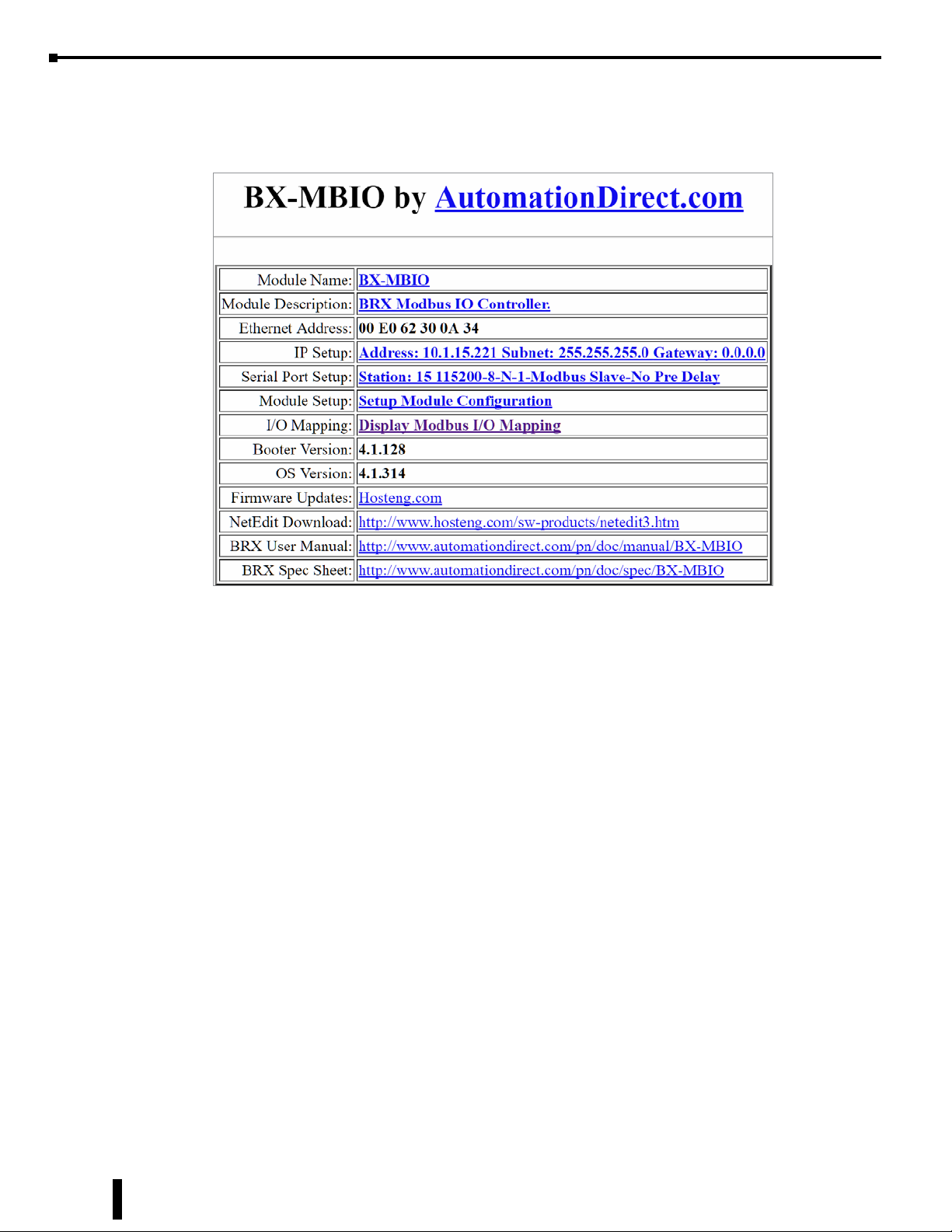
Using NetEdit 3, select the Start Web based Config button to open the Web based configuration page, as
shown below:
Open the Module setup by clicking on the Setup Module Configuration link. This page displays each of
the modules connected to the BX-MBIO, as explained on page 15-24. Edit the configuration of the analog
modules to meet your test requirements.
For this test:
1. Slots 1 to 3 are discrete I/O and do not need to be configured.
2. Slot 4, BX-08THM: Enabled 4 channels, all for type J thermocouple.
3. Slot 5, BX-08AD-2B: Enabled 8 channels, all for 0–10 VDC.
4. Slot 6, BX-08DA-2B: Enabled 8 channels, all for 0–10 VDC.
5. Slot 7, BX-08AD-1: Enabled 8 channels, all for 4–20 mA.
6. Slot 8, BX-08DA-1: Enabled 8 channels, all for 4–20 mA.
Once edits are made, click on the Send button to write the new configuration to the flash memory.
At this point, we have a BX-MBIO that is powered up and available on the network with a proper IP address.
The discrete and analog I/O modules are properly installed and the analog I/O have been configured.
15-36
BRX User Manual, 4th Edition, Rev. F
Page 37
Chapter 15: BX-MBIO Modbus I/O Controller
Troubleshooting with Modbus Poll, continued
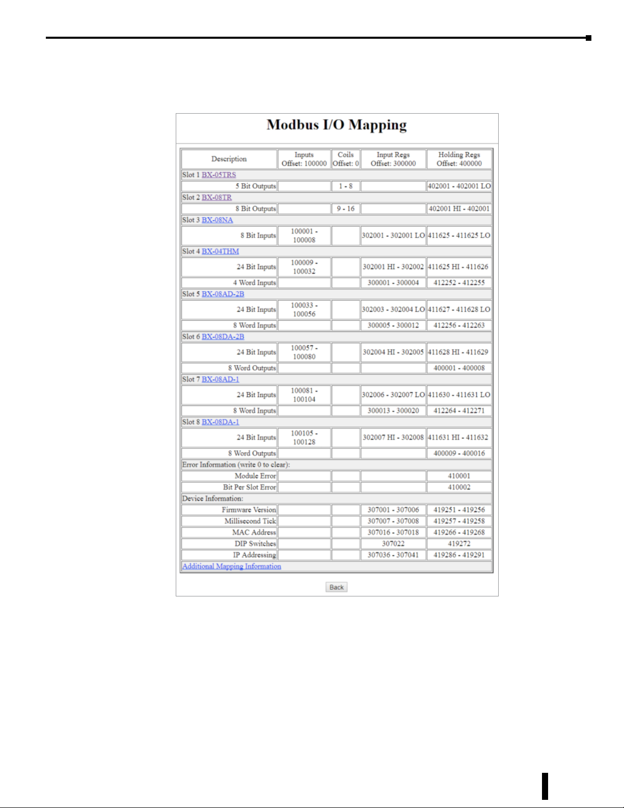
From the main BX-MBIO Web configuration page select the Display Modbus I/O Mapping link. The
following chart shows the Modbus mapping for each module.
We will use the mapping in Modbus Poll to read/write data.
For this test we will use the following addresses:
Slot 1: BX-05TRS. Modbus coils 1–8.
Slot 2: BX-08TR. Modbus coils 9–16.
Slot 3: BX-08NA. Modbus discrete inputs 100001–100008.
When Coil 9 is turned on, discrete input 100001 will come on.
BRX User Manual, 4th Edition, Rev. F
15-37
Page 38
Chapter 15: BX-MBIO Modbus I/O Controller
Troubleshooting with Modbus Poll, continued
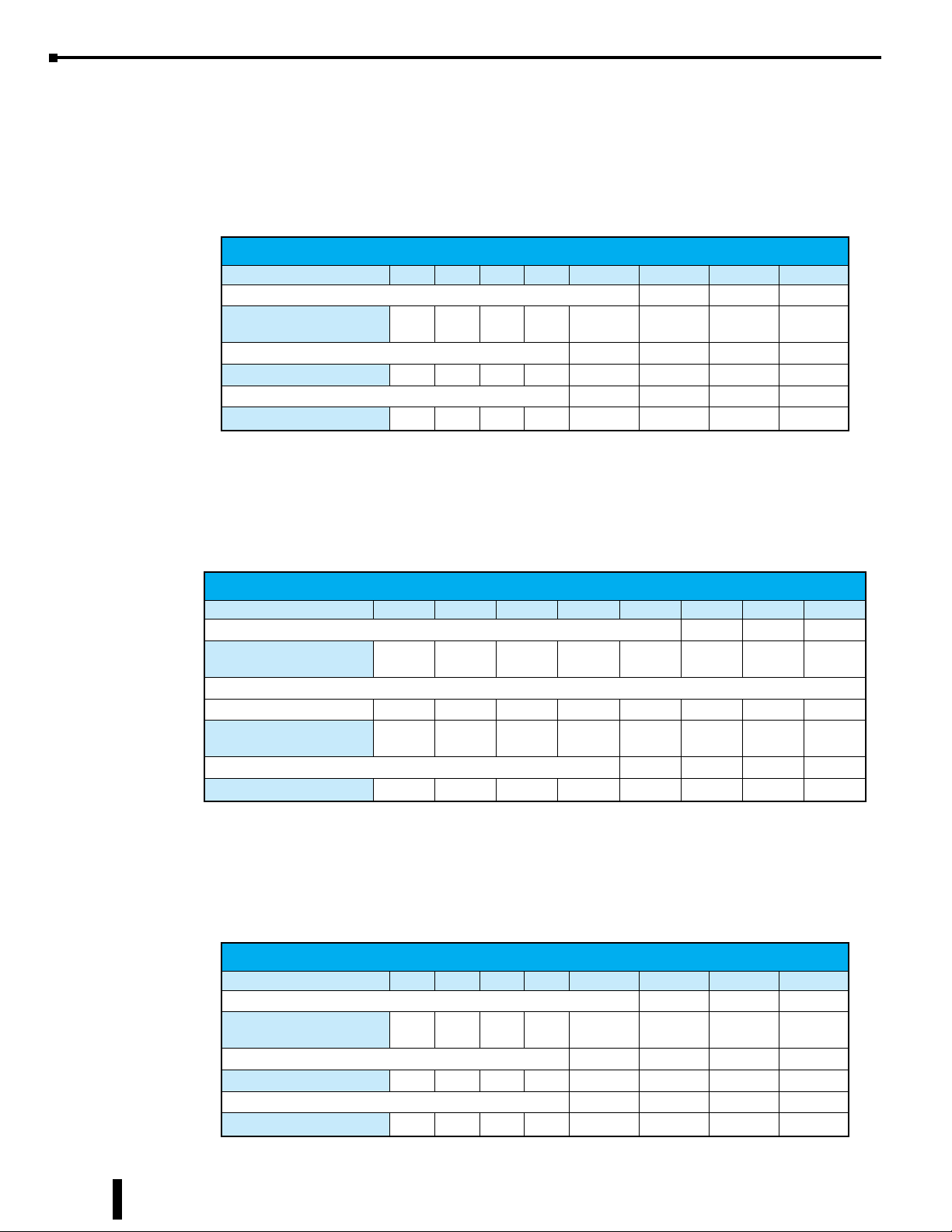
Slot 4: BX-04THM.
Modbus Input Registers 300001–300004. If a type J thermocouple is wired to channel 1 to read
room temperature, the reading will be read in Input Register 300001. There are 24 status flag
bits associated with this module mapped to discrete inputs 100009–1000032. The table below
shows the addressing for the status flags.
Error Flag Specifications
MSB LSB
1st Byte of status ags 100011 100010 100009
Module Status
2nd Byte of status ags 100020 100019 100018 100017
Channel Out of Range
3rd Byte of status ags 100028 100027 100026 100025
Channel Open (Burn Out)
Slot 5:
BX-08AD-2B. Modbus Input Registers 300005–300012. If a transducer is wired to channel
1, the value is read in Input Register 300005. There are 24 status flag bits associated with this
module, mapped to discrete inputs 100033–100056. The table below shows the addressing for
the status flags.
- - - - -
- - - - Channel 4 Channel 3 Channel 2 Channel 1
- - - - Channel 4 Channel 3 Channel 2 Channel 1
Data Not
Valid
Missing
24VDC
Self Test
Failed
Error Flag Specifications
MSB LSB
1st Byte of status ags 100035 100034 100033
Module Status
2nd Byte of status ags
Channel Out of Range
3rd Byte of status ags
Unused
- - - - -
100048 100047 100046 100045 100044 100043 100042 100041
Channel 8Channel 7Channel 6Channel 5Channel 4Channel 3Channel 2Channel
- - - - - - - -
Data Not
Valid
Missing
24VDC
Self Test
Failed
Slot 6:
BX-08DA-2B. Modbus Holding Registers 400001–400008. If channel 1 is used to drive the
speed reference of a VFD, the value is written to Holding Register 400001. There are 24 status
flag bits associated with this module, mapped to discrete inputs 100057–100080. The table
below shows the addressing for the status flags.
Error Flag Specifications
MSB LSB
1st Byte of status ags 100059 100058 100057
Module Status
2nd Byte of status ags
Unused
3rd Byte of status ags
Unused
- - - - -
- - - - - - - -
- - - - - - - -
Data Not
Valid
Missing
24VDC
Self Test
Failed
1
15-38
BRX User Manual, 4th Edition, Rev. F
Page 39
Chapter 15: BX-MBIO Modbus I/O Controller
Troubleshooting with Modbus Poll, continued
Slot 7:
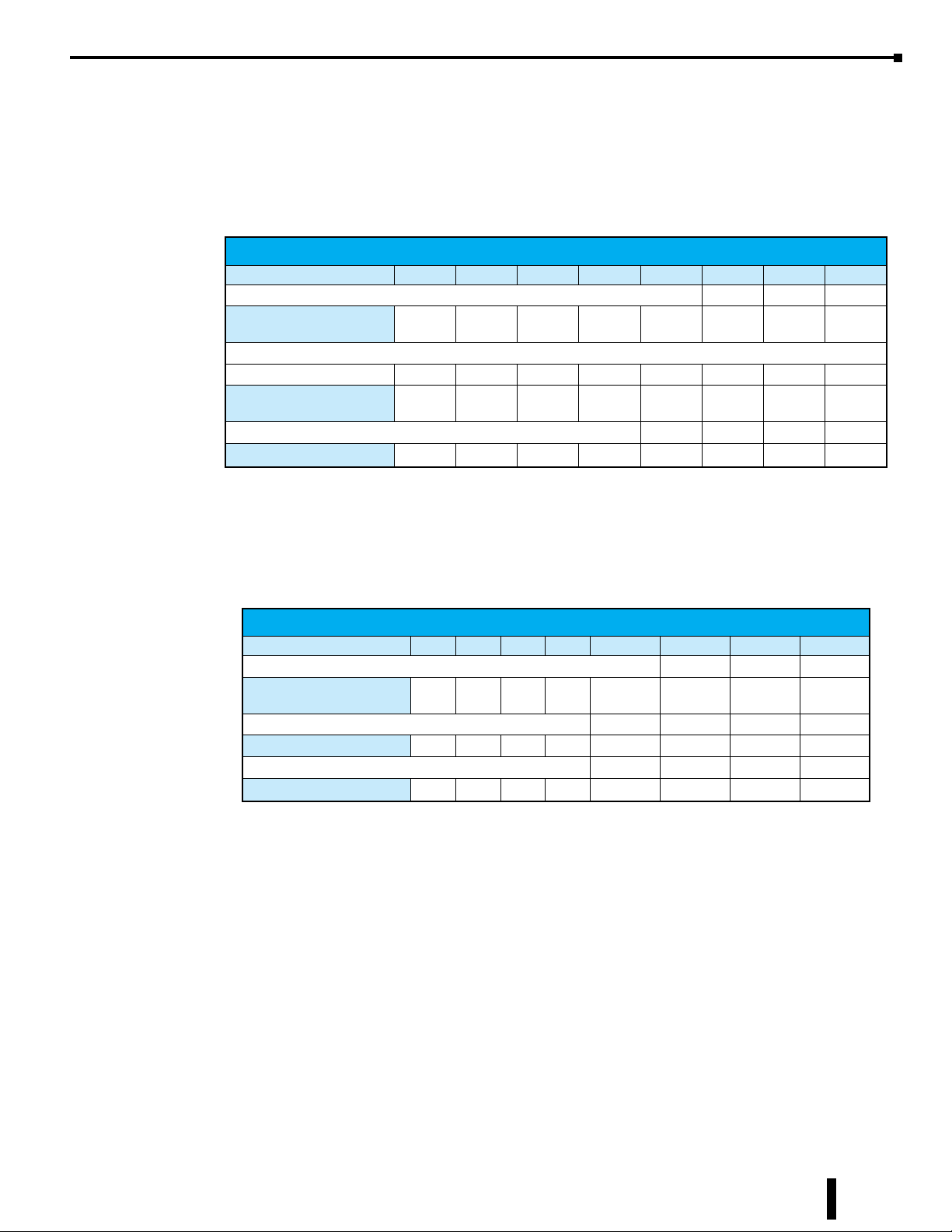
BX-08AD-1. Modbus Input Registers 300013–300020. If a transducer is wired to channel
1, the value is read in Input Register 300013. There are 24 status flag bits associated with this
module, mapped to discrete inputs 100081–100104. The table below shows the addressing for
the status flags.
Error Flag Specifications
MSB LSB
1st Byte of status ags 100083 100082 100081
Module Status
2nd Byte of status ags
Channel Open
(Broken Transmitter)
3rd Byte of status ags
Unused
- - - - -
100096 100095 100094 100093 100092 100091 100090 100089
Channel 8Channel 7Channel 6Channel 5Channel 4Channel 3Channel 2Channel
- - - - - - - -
Data Not
Valid
Missing
24VDC
Self Test
Failed
1
Slot 8:
BX-08DA-1. Modbus Holding Registers 400009-400016. If channel 1 is used to drive the
speed reference of a VFD, the value is written to Holding Register 400009. There are 24 status
flag bits associated with this module, mapped to discrete inputs 100105-100128. The table
below shows the addressing for the status flags.
Error Flag Specifications
MSB LSB
1st Byte of status ags 100107 100106 100105
Module Status
2nd Byte of status ags
Unused
3rd Byte of status ags
Unused
- - - - -
- - - - - - - -
- - - - - - - -
Data Not
Valid
Ready to connect with the Modbus Poll
We have all the information we need to connect with our target BX-MBIO, as summarized below:
1. IP Address of BX-MBIO: 10.1.15.221
Missing
24VDC
Self Test
Failed
2. Coil addresses: 000001–000016. This covers the two relay output modules.
3. Discrete inputs: 100001–100128. This covers the discrete input addresses and the set of 24 status
flags for each of the 5 analog I/O and temperature modules.
4. Input Registers: 300001–300020. This covers the analog and temperature input modules.
5. Holding Registers: 400001–400016. This covers the analog output modules.
With Modbus Poll running, we will start by setting up the read and write blocks for each group of addressing.
BRX User Manual, 4th Edition, Rev. F
15-39
Page 40
Chapter 15: BX-MBIO Modbus I/O Controller
Troubleshooting with Modbus Poll, continued
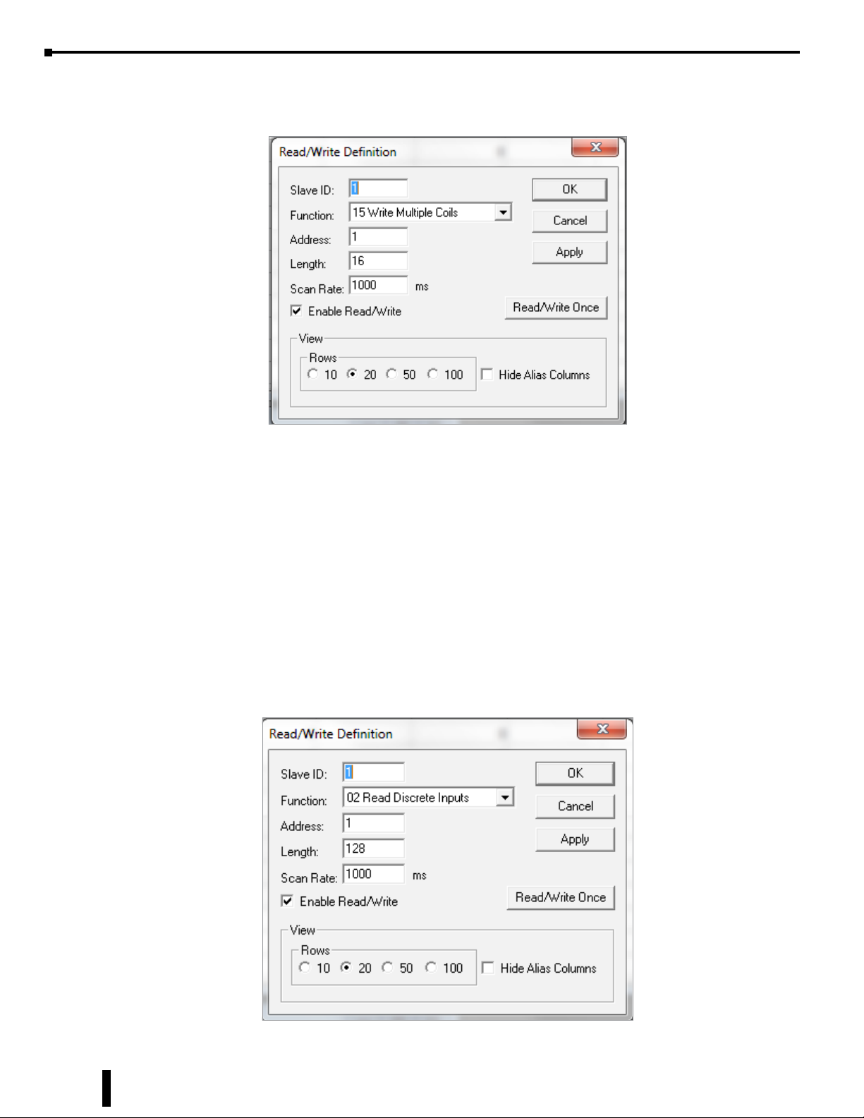
For coils related to BX-05TRS and BX-08TR, use the Mbpoll1 window. Write to coils 1 to 16:
1. From the Display menu, select PLC Address (Base 1).
2. From the Setup menu, select Read/Write Definition.
a. Slave ID = 1, change to match BX-MBIO module ID.
b. Function = 15 Write Multiple Coils
c. Address = 1
d. Length = 16
e. Scan rate = 1000ms (user preference)
f. View rows = 20 (user preference)
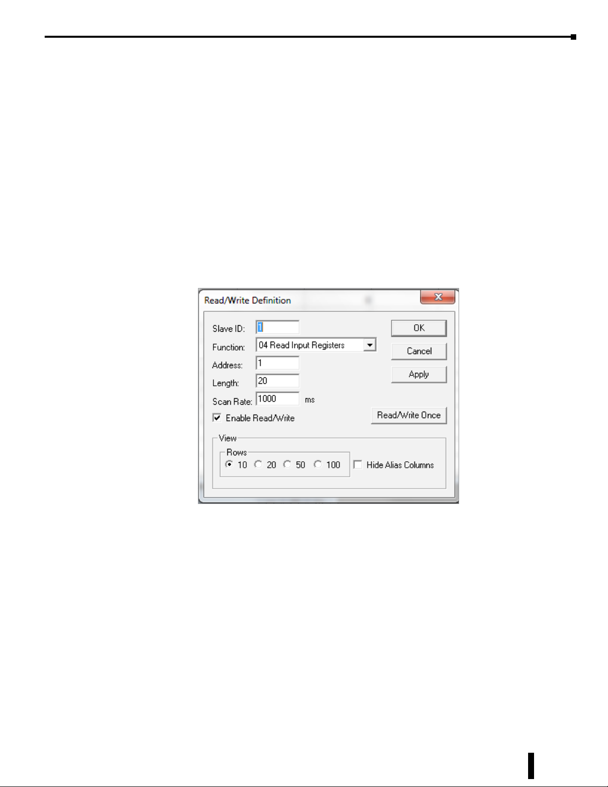
For discrete inputs related to the BX-08NA and the four groups of 24 status flags related to the analog and
temperature modules, use the Mbpoll2 window. Read from discrete inputs 100001 to 100128.
15-40
BRX User Manual, 4th Edition, Rev. F
Page 41
Chapter 15: BX-MBIO Modbus I/O Controller
Troubleshooting with Modbus Poll, continued
1. From the Display menu, select PLC Address (Base 1).
2. From the Setup menu, select Read/Write Definition.
a. Slave ID = 1, change to match BX-MBIO module ID.
b. Function = 02 Read Discrete Inputs
c. Address = 1
d. Length = 128
e. Scan rate = 1000ms (user preference)
f. View rows = 20 (user preference)
For input registers related to the BX-04THM, BX-08AD-2B and BX-08AD-1 modules, use the Mbpoll3
window. Read from input registers 300001 to 300020.
1. From the Display menu, select PLC Address (Base 1).
2. From the Setup menu, select Read/Write Definition.
a. Slave ID = 1, change to match BX-MBIO module ID.
b. Function = 04 Read Input Registers
c. Address = 1
d. Length = 20
e. Scan rate = 1000ms (user preference)
f. View rows = 10 (user preference)
BRX User Manual, 4th Edition, Rev. F
15-41
Page 42
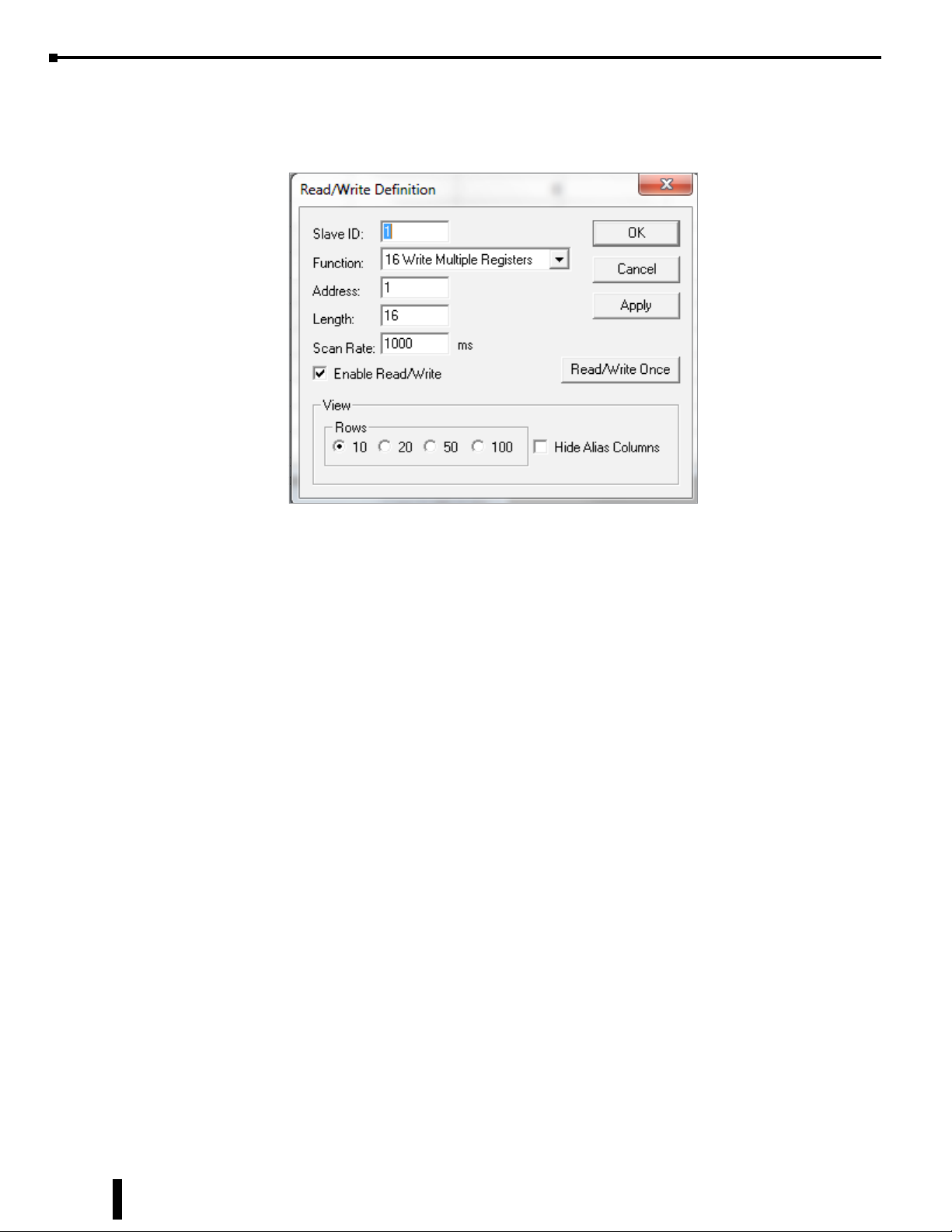
Chapter 15: BX-MBIO Modbus I/O Controller
Troubleshooting with Modbus Poll, continued
For holding registers related to the BX-08DA-2B and BX-08DA-1 modules, use the Mbpoll4 window. Read
from holding registers 400001 to 400016.
1. From the Display menu, select PLC Address (Base 1).
2. From the Setup menu, select Read/Write Definition.
a. Slave ID = 1, change to match BX-MBIO module ID.
b. Function = 16 Write Multiple Registers
c. Address = 1
d. Length = 16
e. Scan rate = 1000ms (user preference)
f. View rows = 10 (user preference)
15-42
BRX User Manual, 4th Edition, Rev. F
Page 43
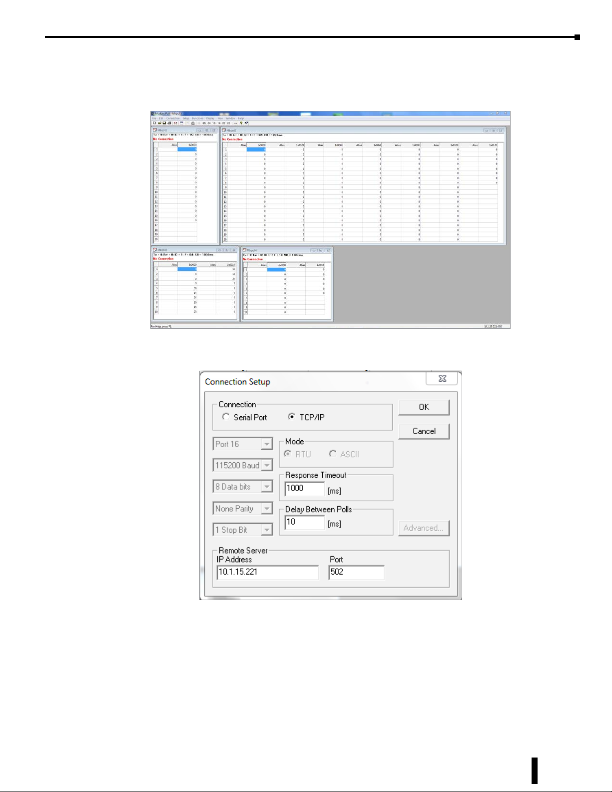
Chapter 15: BX-MBIO Modbus I/O Controller
Troubleshooting with Modbus Poll, continued
Once each addressing group is configured, the Modbus Poll screen should look as follows (user must re-size
windows):
From the Connect menu, select Connect, to establish a connection with the BX-MBIO.
To setup the connection:
1. Connection = select TCP/IP.
2. Response timeout = 1000ms
3. Delay Between Polls = 10ms
4. IP Address = 10.1.15.221, the IP address of BX-MBIO
5. Port = 502
BRX User Manual, 4th Edition, Rev. F
15-43
Page 44

Chapter 15: BX-MBIO Modbus I/O Controller
Troubleshooting with Modbus Poll, continued
Let’s Get Some Values
Now that everything is wired, configured and mapped in Modbus Poll, we can write an output and see the
corresponding input turn on. We will write an output from BX-08TR and that should turn on an input on
the BX-08NA. We will then write a value to the analog output modules, BX-08DA-2B and BX-08DA-1
and we will see the input channel on the BX-08AD-2B and BX-08AD-1 display a value in the range of the
output value.
Discrete I/O: BX-08TR to BX-08NA
• Coil 000009 turns on input 100001
• Coil 000010 turns on input 100002
• Coil 000011 turns on input 100003
• Coil 000012 turns on input 100004
• Coil 000013 turns on input 100005
• Coil 000014 turns on input 100006
• Coil 000015 turns on input 100007
• Coil 000016 turns on input 100008
Temperature input: BX-04THM wired to thermocouple
• Channel 1 data read to 300001
• Channel 2 data read to 300002
• Channel 3 data read to 300003
• Channel 4 data read to 300004
Analog I/O, voltage: BX-08DA-2B to BX-08AD-2B
• Output driven by 400001 wired to input value in 300005
• Output driven by 400002 wired to input value in 300006
• Output driven by 400003 wired to input value in 300007
• Output driven by 400004 wired to input value in 300008
• Output driven by 400005 wired to input value in 300009
• Output driven by 400006 wired to input value in 300010
• Output driven by 400007 wired to input value in 300011
• Output driven by 400008 wired to input value in 300012
Analog I/O, current: BX-08DA-1 to BX-08AD-1
15-44
• Output driven by 400009 wired to input value in 300013
• Output driven by 400010 wired to input value in 300014
• Output driven by 400011 wired to input value in 300015
• Output driven by 400012 wired to input value in 300016
• Output driven by 400013 wired to input value in 300017
• Output driven by 400014 wired to input value in 300018
• Output driven by 400015 wired to input value in 300019
• Output driven by 400016 wired to input value in 300020
BRX User Manual, 4th Edition, Rev. F
Page 45
Chapter 15: BX-MBIO Modbus I/O Controller
Additional BX-EBC100 and BX-MBIO Modbus Mapping Information
Modbus Mapping for I/O
BX-EBC100 and BX-MBIO Discrete Input and Output Modbus Mapping
Modbus Data Type (Bit) Memory Type
Coil Discrete Output
Input Discrete Inputs
BX-EBC100 and BX-MBIO Analog Input and Output Modbus Mapping
Modbus Data Type (Word) Memory Type
Input Register Analog Input Register
Holding Register Analog Output Register 400001 – 400128 128 (256) R/W
Address Range Bit
(Input/Hold Registers)
000001 – 000512
(402001 – 402032)
100001 – 100512
(302001 – 302032)
(411625 – 411656)"
Address Range
Input/Hold Registers
300001 – 300128
(412251 – 412378)
Words (Bytes/Bits) Access
32 (64/512) R/W
32 (64/512) R
Words (Bytes) Access
128 (256) R
System Memory Modbus Mapping
BX-EBC100 and BX-MBIO System Memory Modbus Mapping
Input Registers
307001
Version
Data
MS Tick
Data
Reserved* 307009 – 307010 2 (4) Used by the System
Device
Data
Table continued on next page
307002
307003
307004
307005
307006
307007 – 307008 419257 – 419258 2 (4) Millisecond Tick Data Registers R
307011
307012
307013
307014
307015
307016 – 307018
307019
307020
307021
307022
307023
307024 – 307027
307028
307029
307030
307031
307032
307033
307034
307035
307036 – 307041
307042 – 307100
Holding
Registers
419251
419252
419253
419254
419255
419256
419261
419262
419263
419264
419265
419266 – 419268
419269
419270
419271
419272
419273
419274 – 419277
419278
419279
419280
419281
419282
419283
419284
419285
419286 – 419291
419292 – 419350
Words
(Bytes)
6 (12)
90 (180)
Description Access
1 - OS Major Version
2 - OS Minor Version
3 - OS Build Version
4 - Booter Major Version
5 - Booter Minor Version
6 - Booter Build Version
1 - Version of Device
2 - Family
3 - Processor
4 - Module Type
5 - Status Code
(6-8) - Ethernet Address
9 - RAM Size
10 - Flash Size
11 - Batt Switch
12 - DIP Settings
13 - Media Type
(14-17) - Reserved*
18 - Model Number
19 - Ethernet Speed
20 - Reserved*
21 - IO -tal Byte Count
22 - Bit Input Byte Count
23 - Bit Output Byte Count
24 - Non-bit Input Byte Count
25 - Non-bit Output Byte Count
(26-31) - IP Conguration
(32-90) Reserved*
R
R
BRX User Manual, 4th Edition, Rev. F
15-45
Page 46

Chapter 15: BX-MBIO Modbus I/O Controller
Additional BX-EBC100 & BX-MBIO Modbus Mapping Info, continued
BX-EBC100 and BX-MBIO System Memory Modbus Mapping (continued)
Input Registers
Module IDs 307101 – 307109 419351 – 419359 9 (18)
307201 – 307204
Module
Information
I/O Module
Status
Reserved* 404001 – 408096 4096 (8192) Used by system
Dynamic
Data
Reserved* 410021 – 410276 256 (512) Used by system
Reserved* 411125 – 411188 64 (128) Used by system
Reserved* 419259 – 419260 2 (4) Used by system
Reserved* 460001 – 460200 200 (400) Used by system
* Reserved - used by system. User should not write to these addresses.
Slot 1
307205
307206
307207
307208
307209 – 307236
307401 – 307420
Slot 1
307421
307422
307423 – 307440
307441 – 307580
307581 – 307600
Holding
Registers
419451 – 419454
Slot 1
419455
419456
419457
419458
419459 – 419486
419651 – 419670
Slot 1
419671
419672
419673 – 419690
419691 – 419830
419831 – 419850
410001
410002 – 410006
410007
410008 – 410020
Words
(Bytes)
36 (72)
200 (400)
20 (40)
Description Access
I/O module ID numbers per slot location.
Address 307102 (419352) is for the rst expansion I/O
module, Slot 1.
(4 words per slot)
Slot 0 words; Reserved*
Slot 1 words:
1 - Bit Input Count
2 - Bit Output Count
3 - Non-bit Input Count
4 - Non-bit Output Count
Words for Slot 2 to Slot 8
(20 words per slot)
Slot 0 words; Reserved*
Slot 1 words:
1 - Flags with bits indicating presence of an Error
Bit 0: If set, indicates that Error Value is non-zero
2 - Error Code - refer to Error Codes Table.
3 - 20: Reserved*
Words for Slot 2 to Slot 8
Reserved*
Words per BX-EBC100
1 - Refer to Error Codes Table.
Bits 0 to 11: Error code.
Bit 12: Module error exists. May be triggered by:
1. Internal Error
2. Too much I/O to t into the internal buffer
Bits 13 to 15: Reserved for system use.
Example of error E126: 410001 = 4222 = 107E (hex),
Where 126 = 7E (hex), plus 4096 when bit 12 is on.
2–6 - Reserved*
7 -
Link Monitor Timeout (EBC communication watchdog
timer) - 0 to disable; range 0 - 10000ms.
8-20 - Reserved*
R
R
R
R
W
15-46
BRX User Manual, 4th Edition, Rev. F
Page 47

Chapter 15: BX-MBIO Modbus I/O Controller
Additional BX-EBC100 & BX-MBIO Modbus Mapping Info, continued
Error Codes
BX-EBC100 and BX-MBIO Error Codes
Error Code Description Additional Information
E000 No Error
E013 This is a buffer overow condition
E119 Data not valid.
E126 Module is write protected.
E165 Module conguration is incorrect.
This error indicates an internal buffer overow condition that should be reported.
This error indicates that more I/O was found in the system than the rmware can handle.
Can also be an internal error that should be reported.
This Error can show up if the module is activeliy being used by a Do-more! PLC.
Also, this error may be the result of DIP switch 5 being on which write-protects the module.
Several functions are not available while the module is being used from a Do-more! PLC.
This Error indicates that the I/O conguration has changed from what has been stored for
things such as analog cong data.
Moving congured analog modules around in the base will cause this error.
The conguration will need to be re-written to x this.
BRX User Manual, 4th Edition, Rev. F
15-47
Page 48

Chapter 15: BX-MBIO Modbus I/O Controller
Notes:
15-48
BRX User Manual, 4th Edition, Rev. F
 Loading...