

Bruno VPL-3100 Installation Manual

VPL-3100
VERTICAL PLATFORM
LIFT
Technical Service email: service@bruno.com
www.bruno.com
DEALER:
1780 EXECUTIVE DR., P.O. BOX 84, OCONOMOWOC, WI 53066 USA
INSTALLATION MANUAL
MAN-3100-1
06-02-2008
TELEPHONE:(262) 567-4990
FAX: (262) 953-5501
1-800-882-8183
• Check for shipping damage immediately upon receipt. Contact
the shipper with any damage claims.
• Check the contents against the packing list before leaving the
shop to begin on-site installation. Immediately report any
discrepancies to Bruno Independent Living Aids, Inc.®.
Read and understand the installation manual prior to proceeding
with the installation.
Throughout this manual, safety precautions are provided
to identify potentially hazardous situations and to advise how to
avoid them.
Warning– Indicates a potentially hazardous situation
that, if not avoided, could cause serious bodily
injury and / or property damage.
Caution– Indicates a potentially hazardous situation
that, if not avoided, could cause damage to the
unit and / or moderate injury.
Electrical Hazard– Indicates a potentially hazardous
electrical situation that, if not avoided,
could cause damage to the unit and /
or moderate injury.
Lubriplate® is a registered trademark of Lubriplate Division (Fiske Brothers).
Vise-Grip® is a registered trademark of Petersen Manufacturing Co.
©2008,2006 Bruno Independent Living Aids, Inc.®
2
VPL-3100 06-02-2008

TABLE OF CONTENTS
Specications ........................................... 4
Tools ................................................. 5
Safety................................................. 6
Pre-Installation Checks ................................. 7-8
Installation
Main component .....................................9-10
Adjusting top landing/nal limit switches ..................... 11
Standard gate installation .............................12-14
Cam/actuator installation and adjustment (standard gate) .......15-16
Wide gate installation ................................17-19
Cam/actuator installation and adjustment (wide gate) ..........20-21
Wiring the call/send and gate ...........................23-24
Mounting the call/send box .............................16-17
Securing the unit ...................................... 25
Testing ............................................. 25
Completing the installation ............................... 26
Moving the ramp, ramp actuator and vertical bar to the opposite side . 27-31
Optional gate interlock installation .........................32-33
Optional electric door interlock installation ...................34-35
Emergency and cold-weather operation ........................ 36
Troubleshooting .......................................37-38
Wiring schematic ......................................39-40
Exploded views and drawings .............................41-53
Warranty.............................................. 54
VPL-3100 06-02-2008
3
©2008,2006 Bruno Independent Living Aids, Inc.®
SPECIFICATIONS
Load Capacity 750 lbs. (340 kg)
Weight of Unit
VPL-3153 752 lbs. (341 kg)
VPL-3175 825 (374 kg)
Rated Speed 9 FPM (2.75 m/mn)
Power Supply 120 VAC, 15A, single phase, 60 Hz
Motor 1 HP, 120 VAC
Control Voltage 24 VAC, motor 120 VAC
Maximum Travel 53” (1.3 m) unit and 75” (1.9 m) unit
Platform Size standard: 34” x 48” (86 x 122 cm); optional: 34” x 54”
(86 x 137 cm)
Emergency Operation provision for manual hand wheel
Standard Features keyed, constant-pressure controls on platform with
emergency stop switch; all-weather protected controls
and switches; platform bottom safety panel, top and
bottom limit switches, automatic folding ramp
Optional Features
landing call/send station with key; top landing gate
including call/send station with key and Bruno interlock;
34”x54” non-skid platform
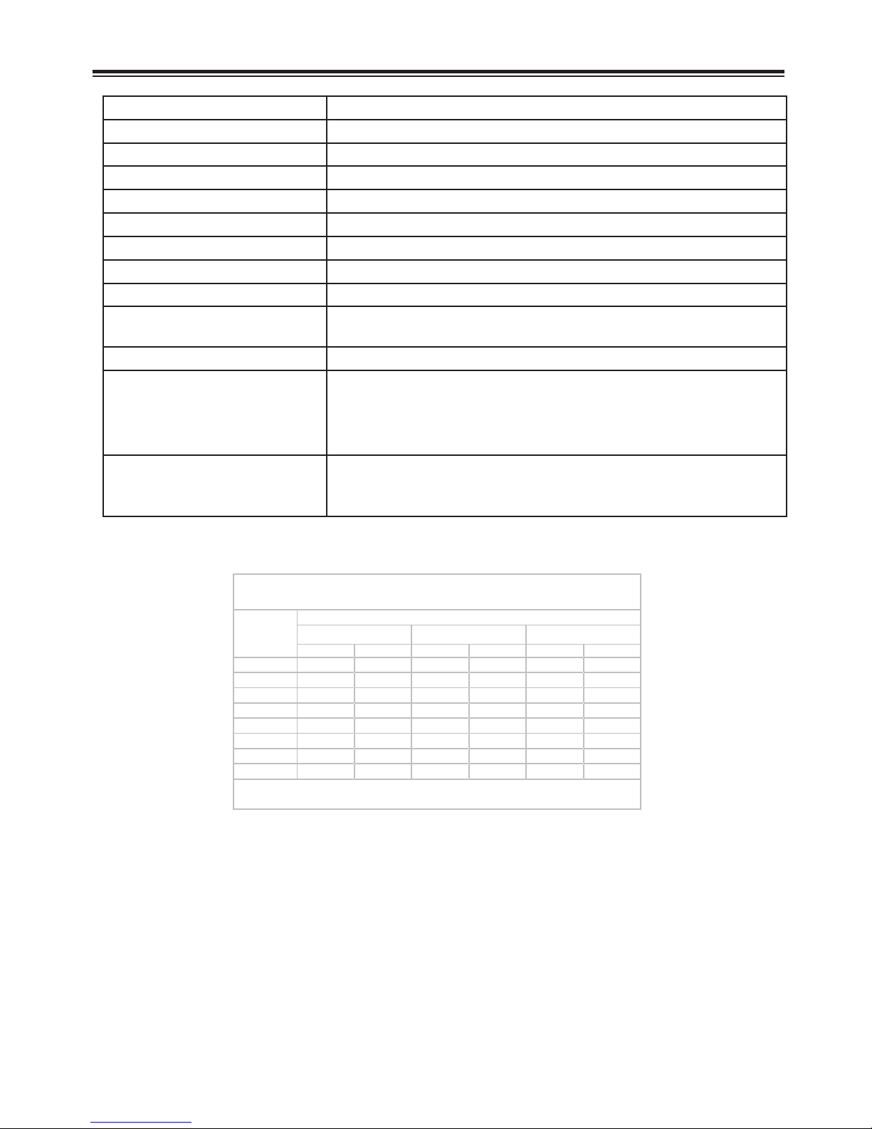
Recommended Bolt Torque
US
Recommended Torque
Size
Grade 5 Grade 8 18-8 S/S
Coarse Fine Coarse Fine Coarse Fine
1/4 8 10 12 14 6.3 7.8
5/16 17 19 24 27 11 11.8
3/8 31 35 44 49 20 22
7/16 49 55 70 78 31 33
1/2 75 85 105 120 43 45
9/16 110 120 155 170 57 63
5/8 150 170 284 323 93 104
3/4 270 295 510 568 128 124
Units are ft.-lbs.
These torque values are provided for
reference only. If specic torque is
required for an installation operation, it
will be indicated.
©2008,2006 Bruno Independent Living Aids, Inc.®
4
VPL-3100 06-02-2008
Tools Needed for Installation
• 1/2” dia. x 3” lg. masonry anchors
• Sawzall® or similar reciprocating saw
• Circular saw
• Straight and Phillips screwdrivers (or bits)
• Combination wrench sets (SAE)
• Allen wrench set (SAE)
• Socket wrench set (SAE)
• Level (4-foot) or inclinometer
• Torque wrench (20 lb.-ft to 133 lb.-ft) low-prole,
open-end wrench style preferred
• Voltohmmeter and probes
• Wire stripper
• Crimping tool
• Tape measure
• Pry bar
• Hammer and mallets
• Extension cord for power tools (50’ minimum)
• Vise-Grips®
• Appliance dolly
• Hammer drill
• Masonry bits, 1/2” and 3/8”
• Reversible drill, 3/8”, and bits
• File
• Hammer drill, 1/2” for concrete fasteners
TOOLS
VPL-3100 06-02-2008
5
©2008,2006 Bruno Independent Living Aids, Inc.®

lb
kg
SAFETY
There are no USER
serviceable parts in
the electrical box.
• Never exceed the maximum rated lift
capacity of 750 lbs. (340 kg).
• Never use the VPL-3100 to lift freight or
other materials than intended by design.
• Read and understand the installation
manual prior to installing the VPL-3100.
• Wear appropriate safety protection equipment for your head, eyes, hands and feet
during all phases of the installation.
• Lift components are heavy. Use extreme
caution when lifting them to the installation position to avoid personal injury and
damage to the equipment.
WARNING
RISK OF
ELECTROCUTION
AND
DEATH
Remove all metal
jewelry (rings, bracelets
etc.) which might
accidentally come in
contact with an
electrical terminal.
• Keep panels and protective coverings in
place to avoid potentially fatal injury.
• Disconnect power from the unit before
performing any electrical or mechanical
service operations.
• Never bypass sensor switches which prevent
accidental start up when protective panels
are removed.
• Do not work alone.
• Be aware of the location of others in the
work zone.
• Do not wear jewelry or loose clothing.
• Lock the wheels of any mobility device
riding on the platform.
• Use only recommended anchor fasteners.
• Check for applicable local codes and
regulations.
• Failure to comply with the above could
render the warranty nulL and void.
©2008,2006 Bruno Independent Living Aids, Inc.®
6
VPL-3100 06-02-2008
PRIOR TO INSTALLATION
• Visit the installation site.
• Verify that a dedicated 15A electrical circuit
is available for installation of the VPL-3100
and that it has been installed by a qualied
electrical contractor in compliance with local
codes and regulations.
• Check for correct voltage and supply wire
A solid foundation is key
to a successful
installation.
Never install the
VPL-3100 on an asphalt
driveway, patio stones,
concrete blocks or other
unstable surfaces.
size.
• Conrm the structural integrity of the fascia.
• Conrm the existence of a properly constructed
concrete base that is level and at.
• Verify that the walls and oors are level.
• Verify hoistway clearances, nished openings
for gates and doors, ceiling break clearances
and electrical layout.
PRE-INSTALLATION CHECKS
The fascia must be
smooth, vertical and
structurally sound.
Check all applicable
local codes.
• Locate and eliminate possible pinch points.
• Determine the path to be used to move the
unit into place. Make sure it is free of obstacles.
• Double-check the order form to verify receipt
of all parts needed for installation.
• Make sure that the ramp and the ramp actuator are on the correct side (right or left) for
the installation.
To move the ramp/ramp actuator to the
opposite side, see “MOVING THE RAMP AND
RAMP ACTUATOR TO THE OPPOSITE SIDE”
appearing later in this manual.
VPL-3100 06-02-2008
7
©2008,2006 Bruno Independent Living Aids, Inc.®

PRE-INSTALLATION CHECKS
PRIOR TO INSTALLATION
(continued)
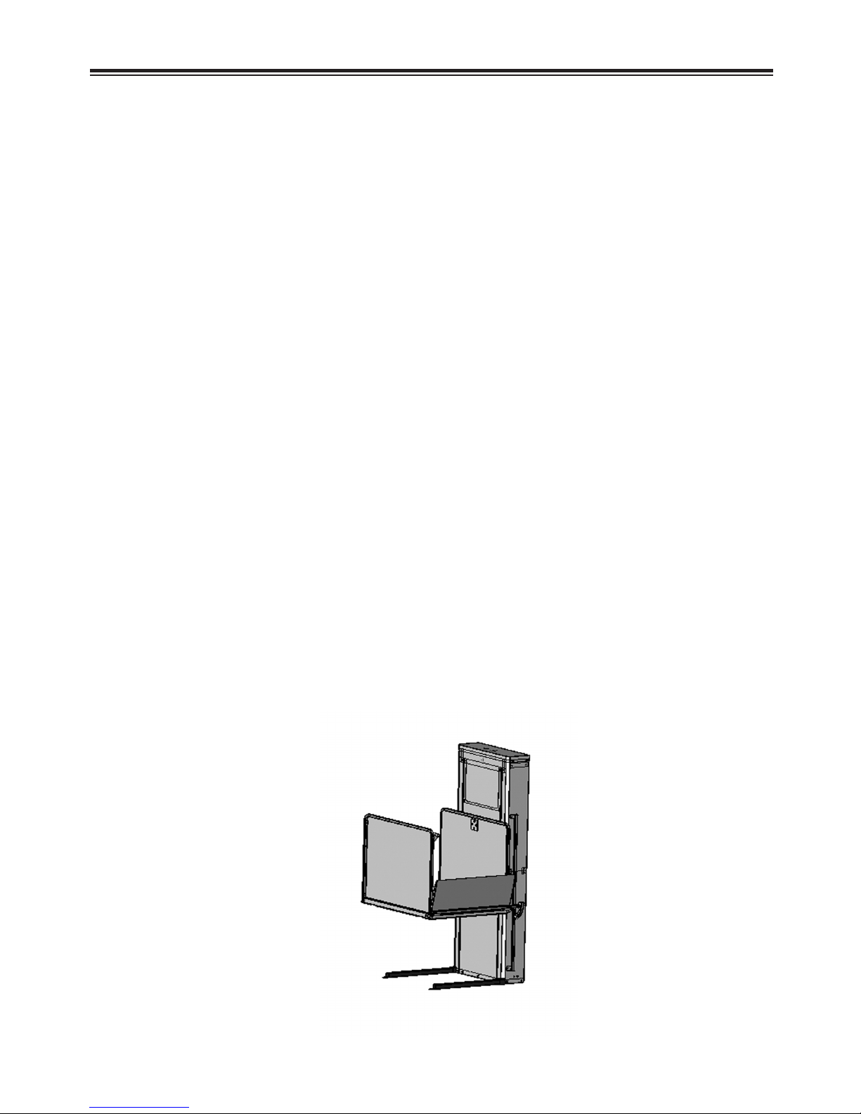
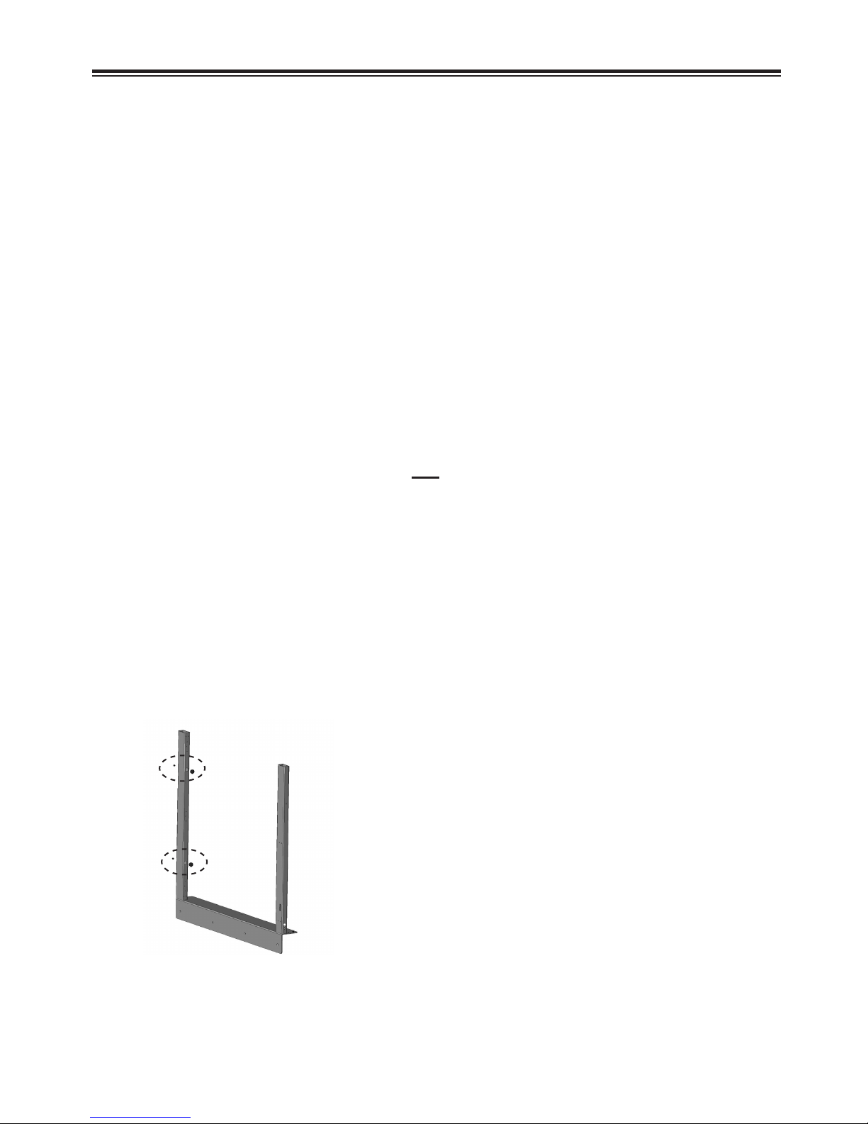
• VSL-3175
The VSL-3175 is shipped disassembled.
Prior to installation, mount the platform to
the tower.
1. From the platform, remove the vertical
panel with the pushbutton controls.
2. Move the platform into position next to the
tower.
NOTE: A skate dolly works well for this purpose.
3. Attach the platform to the tower using the
bolts, washers, lockwashers and nuts
provided.
4. Remount the vertical panel with the
pushbutton controls.
©2008,2006 Bruno Independent Living Aids, Inc.®
8
VPL-3100 06-02-2008
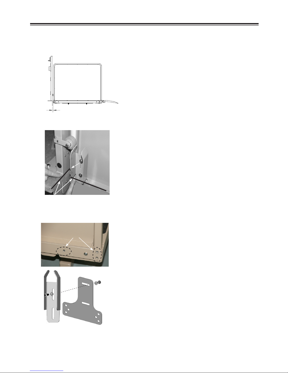
INSTALLATION OF MAIN COMPONENT
The VPL-3100 must be installed on a level,
smooth concrete base with a minimum thickness of 4” (10 cm), in place prior to installa-
tion and not provided by Bruno.
1. Decide on which side of the unit the call/
Per ASME Code
A18.1, there must be
a clearance of 3/8”
to 3/4” (10 mm to
19 mm) between
the platform and the
fascia.
send and gate wire harnesses will be routed.
This is easier to do before placing the unit in
the installation position.
2. Place the VPL-3100 in its approximate nal
position on the concrete base.
3. Align the platform to the opening provided at
the top landing for exiting the VPL.
4. Connect the VPL-3100 power cord to the
dedicated power source (provided by others
and in place prior to installation).
INSTALLATION
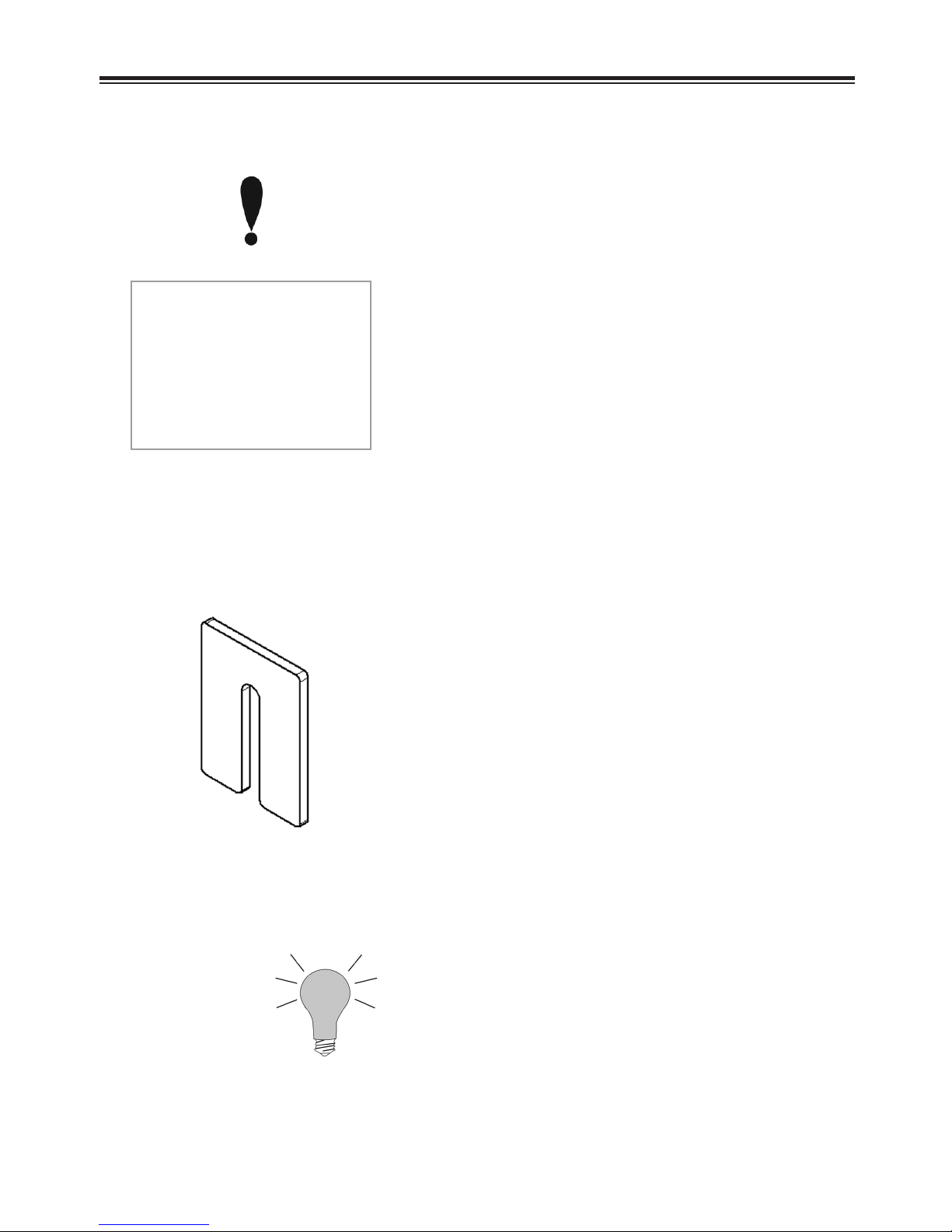
shim
5. Test operation of the VPL-3100 using the
platform control.
6. Verify that the unit is plumb, side-to-side
and front-to-back. Shim base if necessary.
NOTE: Align the shims (provided-see left) with
the mounting holes to keep the shims in
place when fasteners are inserted.
7. If the height of the unit was ordered based on
a specic installation, run the platform to the
top landing.
Otherwise, skip to the next step.
8. Run the unit up until it stops at the factoryset maximum height.
9. Measure from the platform to the top of the
landing. If the landing is above the platform, you will measure this number of inches
ABOVE the mark placed on the channel at the
factory, near the limit switch. If the landing is
below the platform, you will measure BELOW
the mark.
VPL-3100 06-02-2008
9
©2008,2006 Bruno Independent Living Aids, Inc.®
INSTALLATION
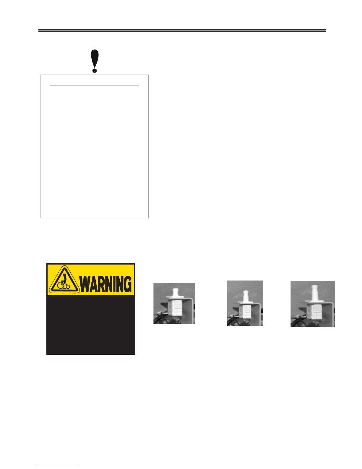
Top Cover Safety Switch
This is a push-pull switch.
When the top cap is in place,
the switch is closed, permitting
the unit to operate normally.
When the top cover is
removed, the switch is open,
and the unit will not operate.
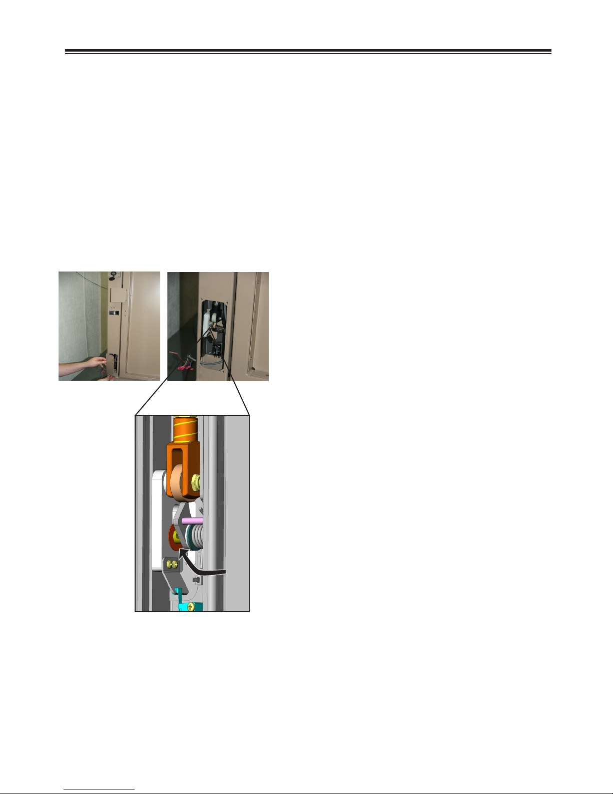
NOTE: Steps 10—14 may have been done
when the unit was removed from the shipping pallet. If so, proceed to the next section.
10. Loosen but do not remove the (3) screws
at the bottom of the front panel.
11. Loosen the (2) screws on each side of the
top cover.
DURING INSTALLATION
AND SERVICE WORK ONLY,
enable unit operation by
pulling up on the switch until it
snaps into position.
Remounting and securing the
top cover pushes the switch
down to its normal operating
position.
Moving parts can
crush and cut.
12. Slide the top cover up and off.
13. Remove the (3) screw along the top of the
front access panel.
14. Slide the front access panel up and off.
Set to the side.
NOTE: Removal of the top cap opens the top
housing sensor switch. This
prevents accidental movement of the
platform. See left and below.
Use extreme caution
around open drive
components when
switch is up.
©2008,2006 Bruno Independent Living Aids, Inc.®
with top cover in
place, switch is
pushed down and
unit operates.
with top cover
removed, switch is
in middle position
and unit will not
operate
pull up for service
15. ALWAYS replace the top cover after com-
pletion of installation/service operations.
10
VPL-3100 06-02-2008

ADJUSTING TOP LANDING/FINAL
LIMIT SWITCHES
1. Loosen the top landing/nal limit switch
bracket hardware.
2. Slide the bracket up or down, depending
on the measurement taken on the previous
page.
3. The bottom of the bracket should line up
with the new mark made on the vertical
channel.
4. Tighten the limit switch bracket hardware.
Align bracket edge to be
parallel to vertical column
before tightening to ensure
proper limit switch operation.
5. Retest operation and recheck that the unit
stops at the correct height. Readjust if
necessary.
INSTALLATION
VPL-3100 06-02-2008
11
©2008,2006 Bruno Independent Living Aids, Inc.®
INSTALLATION
STANDARD GATE INSTALLATION
Wide gate (90° platform) instructions appear later in this manual.
NOTE: The instructions given below apply to the installation of a Bruno top
landing gate on a Bruno lift.
If installing a top landing gate other than a Bruno gate, refer to the
instructions provided by the gate manufacturer.
Prior to the installation of either a Bruno and or a non-Bruno top
landing gate, check local codes and regulations in force.
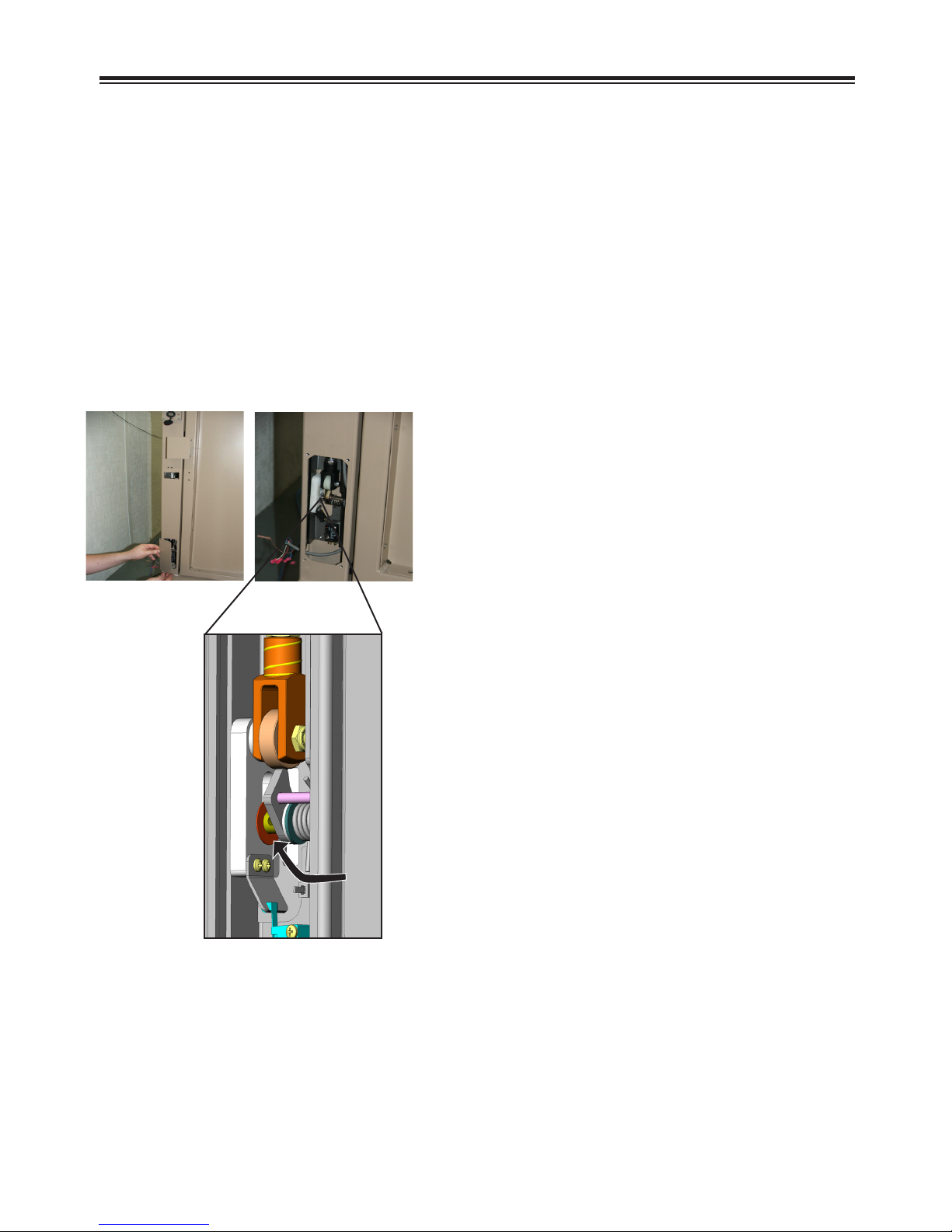
1. Before positioning the gate on the
landing:
a. remove the access cover from the
lower lock switch (see left);
washer against
yoke bracket
©2008,2006 Bruno Independent Living Aids, Inc.®
b. make sure the at washer (assembled
in the factory) is against the yoke bracket
(see left);
12
VPL-3100 06-02-2008
STANDARD GATE INSTALLATION
(continued)
1. Before positioning the gate on the
landing (continued):
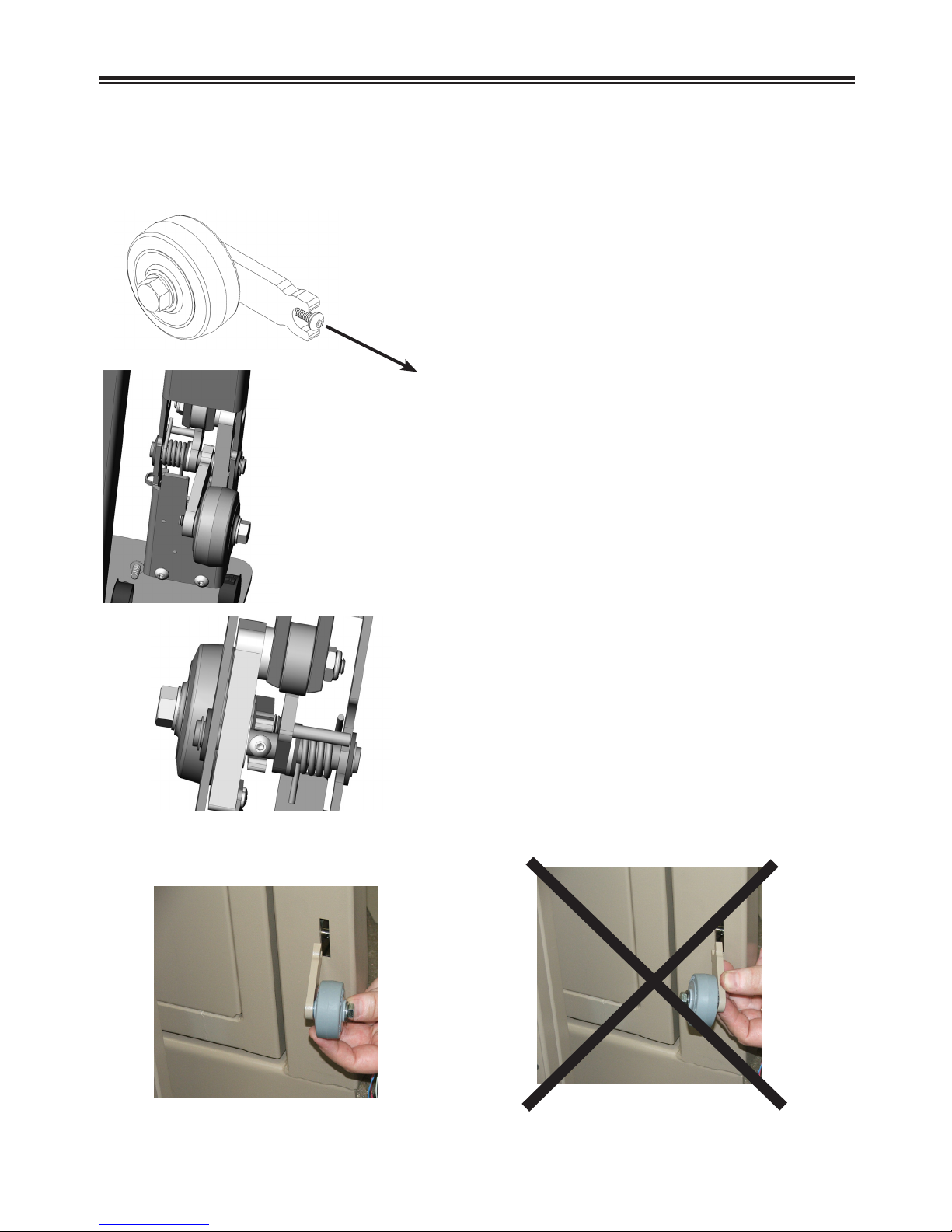
c. mount the gate wheel (see left):
• remove the #8 screw and lockwasher
from the wheel assembly;
•assemble the wheel to the interlock,
noting orientation (see left and below);
INSTALLATION
wheel mounting,
view from rear
wheel mounting,
view from front
• secure the wheel with the #8 screw and
lockwasher.
NOTE: Do not remount the access door at
this time. You will require access to this
area for wiring.
correct orientation
VPL-3100 06-02-2008
13
WRONG orientation
©2008,2006 Bruno Independent Living Aids, Inc.®
INSTALLATION
STANDARD GATE INSTALLATION
(continued)
2. Orient the landing gate so that the
3. Decide on the routing of the wiring from
4. If necessary, mark and drill a 1/2” hole
5. Secure the gate in place using (2) of its
smooth, ush surface faces the platform.
NOTE: Refer to the Technical Specications
at the back of this manual for proper
gate-to-platform alignment.
the gate interlock post to the VPL. It can
exit the interlock post at the side or the
bottom of the post.
in the landing, or the landing post, to
route wires back to the machine.
sill mounting screws.
6. Check that the gate is level
(horizontally and vertically) and
plumb. This is critical for proper door
closing speed and latch alignment. Use
provided shims if necessary.
7. Secure the gate post to the hand railing
using the holes in the gate post or with
an angle bracket.
NOTE: Bruno does not provide the
mounting fasteners for the
landing gate.
However, it DOES provide angle
brackets.
8. Recheck that the gate is level
(horizontally and vertically) and
plumb. This is critical for proper door
closing speed and latch alignment. Use
provided shims if necessary.
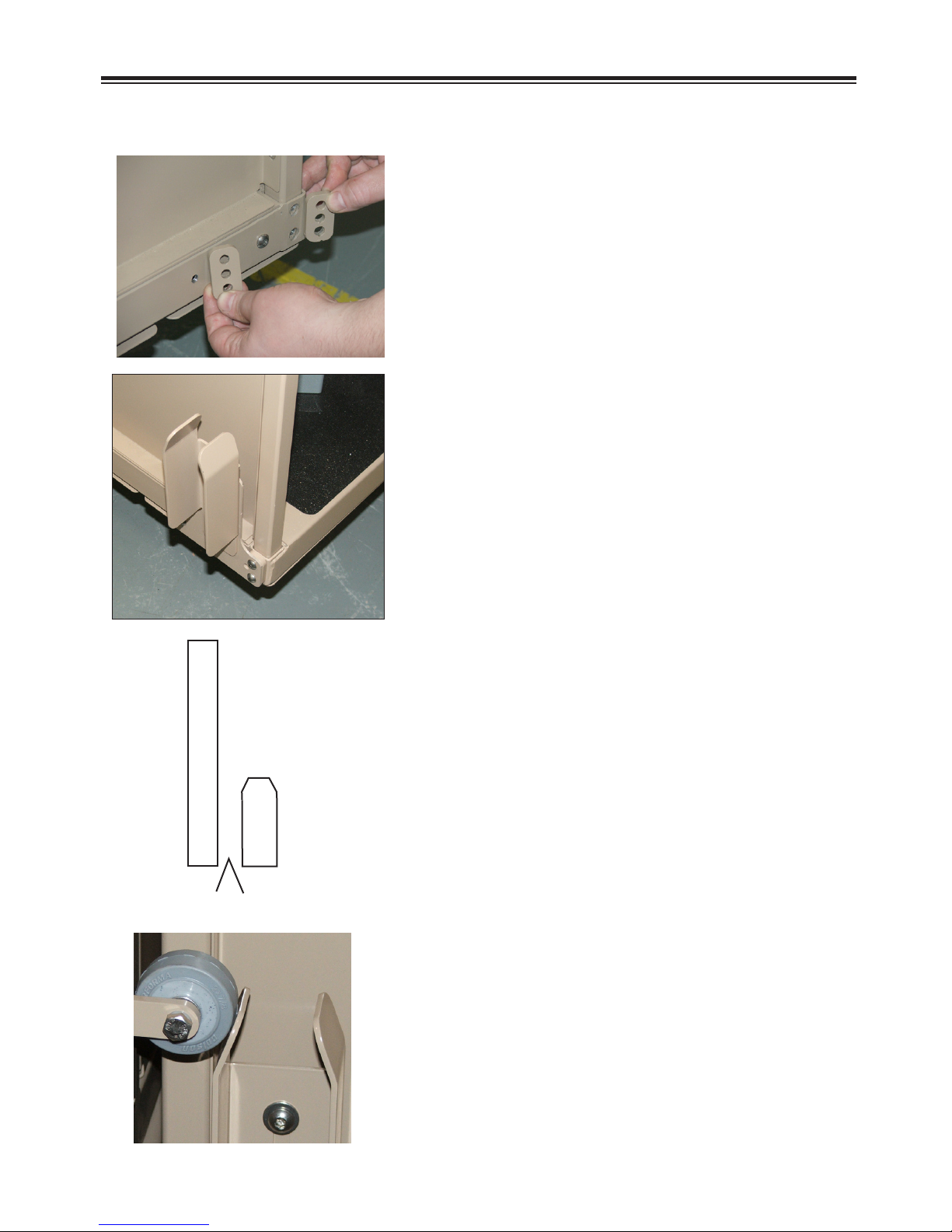
9. Install the black caps (provided in parts
kit) on both sides of the gate support
(see left).
caps on both sides
of support
(left-hand shown)
©2008,2006 Bruno Independent Living Aids, Inc.®
10. Finish securing the gate using the
remaining hardware on the horizontal
and vertical sills.
14
VPL-3100 06-02-2008
INSTALLATION
CAM/ACTUATOR INSTALLATION AND ADJUSTMENT
(standard gate)
1. Verify the required 3/8” to 3/4” (10 mm to
19 mm) running clearance.
3/8” to 3/4” (10 mm to 19 mm)
platform-to-gate running clearance
2. Perform nal adjustment operations on the
gate actuator.
NOTE: The actuator is part of the gate
interlock. This is a mechanical
1.5” (4 cm)
below landing
interlock released by the motion of
the platform. A series of electrical
contacts prohibits platform operation
when the interlock is engaged.
measure from top of landing to
top of square tube (platform)
Remove (3)
screws.
left-hand shown
a. Start with the platform 1.5” (4 cm) below
the landing (see left, and Technical
Specications at the rear of this manual).
b. Remove (3) screws from the platform.
c. Loosely assemble the gate actuator bracket.
VPL-3100 06-02-2008
15
©2008,2006 Bruno Independent Living Aids, Inc.®
INSTALLATION
CAM/ACTUATOR INSTALLATION AND ADJUSTMENT
standard gate (continued)
d. Mount the loosely-assembled bracket to
the platform using the rectangular
spacers and screws as shown.
G
A
T
E
P
O
ACTUATOR
S
T
2” (5 cm)
e. Slide the cam horizontally so that a 2”
(5 cm) gap exists between the gate
post and the at edge of the actuator.
f. Slide the actuator vertically (up) until its
angled edge just touches the cam
(below, left).
g. Tighten all actuator/cam hardware.
2. Run the vertical platform lift up.
NOTE: When the unit reaches the landing
level, the gate should be unlocked.
3. Re-verify clearances and check that the gate
and platform align properly.
©2008,2006 Bruno Independent Living Aids, Inc.®
16
VPL-3100 06-02-2008
INSTALLATION
WIDE GATE (90° PLATFORM) INSTALLATION
NOTE: The instructions given below apply to the installation of a Bruno top
landing gate on a Bruno lift.
If installing a top landing gate other than a Bruno gate, refer to the
instructions provided by the gate manufacturer.
Prior to the installation of either a Bruno and or a non-Bruno top
landing gate, check local codes and regulations in force.
1. Before positioning the gate on the
landing:
a. remove the access cover from the
lower lock switch (see left);
washer against
yoke bracket
VPL-3100 06-02-2008
b. make sure the at washer (assembled
in the factory) is against the yoke bracket
(see left);
17
©2008,2006 Bruno Independent Living Aids, Inc.®
 Loading...