


www.bruno.com
1780 EXECUTIVE DR., P.O. BOX 84, OCONOMOWOC, WI 53066 USA
TELEPHONE:(262) 567-4990
FAX: (262) 953-5501
Bruno invites your calls at: |
1-800-882-8183 |
|
TOLLFREE: US & CANADA |
Technical Service email: service@bruno.com |
|
Technical Service fax: (262) 953-5503 |
|
DEALER : |
INSTALLATION MANUAL |
|
|
MAN-2000-UL 08-16-2004

IMPORTANT NOTES
NOTE: Please locate the metal templates for drilling the mounting holes for the lower charge bracket.
This stairway elevator is
FOR INDOOR USE ONLY in enclosed heated locations
above 35 F (2
F (2 C).
C).
The warranty for the Electra-RideTM Elite Stairway Elevator is rendered null and void
if the unit is installed by
anyone other than an authorized Bruno dealer.
Electra-RideTM Elite is a trademark of Bruno Independent Living Aids, Inc.® |
|
|
©2004,2001 BRUNO INDEPENDENT LIVING AIDS, INC.® |
2 |
SRE-2000 RES UL 08-16-2004 |

Important Notes...................................................................................................... |
2 |
FCC Regulations..................................................................................................... |
4 |
Specifications.......................................................................................................... |
5 |
Introduction............................................................................................................. |
6 |
Carton Contents...................................................................................................... |
7 |
Tools Needed for Installation.................................................................................. |
8 |
Overview of Installation........................................................................................... |
9-10 |
INSTALLATION |
|
Fitting the Rail.............................................................................................. |
11 |
Application Guide......................................................................................... |
12-13 |
Distinguishing Between Rightand Left-Hand Charge Bumper Brackets.... |
14 |
Cutting the Rail and Installing Lower Bumper............................................... |
15-16 |
Placing the Rail Clamps and Rail Sections.................................................. |
17-21 |
Routing the Cable........................................................................................ |
22 |
Mounting the Carriage, Upper Bumper and Upper End Cap....................... |
23 |
Adjusting the Carriage Angle....................................................................... |
24 |
Mounting the Footrest Assembly.................................................................. |
25 |
Mounting the Seat Assembly....................................................................... |
26-27 |
Seat Height Adjustment............................................................................... |
27 |
Mounting the Final Limit Ramp Kit............................................................... |
28 |
Standard IR Call/Send Transmitters............................................................ |
29-30 |
Testing the Call/Send Transmitters.............................................................. |
31 |
Learning the Call/Send Transmitters............................................................ |
32-33 |
Call/Send Transmitter Battery...................................................................... |
33 |
Lubrication.................................................................................................... |
34 |
ELECTRICAL |
|
Circuit Board Diagnostics............................................................................. |
35-36 |
Circuit Breaker............................................................................................. |
37 |
Battery Charger............................................................................................ |
38-39 |
CONVERSION TO RIGHT-HAND INSTALLATION |
|
Reversing Connections................................................................................ |
40 |
Converting the Carriage for Right-Hand Installation..................................... |
41-42 |
Changing the Rocker Switch to the Left Arm............................................... |
43 |
SPEED CONTROL ADJUSTMENT |
|
Speed Control Location and Adjustment..................................................... |
44 |
MAINTENANCE |
|
Vacation/Long-Term Storage....................................................................... |
45 |
Yearly Maintenance Operations................................................................... |
46 |
OVERSPEED (optional).......................................................................................... |
47 |
SCHEMATICS AND EXPLODED VIEWS.............................................................. |
48-89 |
TROUBLESHOOTING............................................................................................ |
90-91 |
WARRANTY........................................................................................................... |
92 |
SRE-2000 RES UL 08-16-2004 |
3 |
©2004,2001 BRUNO INDEPENDENT LIVING AIDS, INC.® |

FCC REGULATIONS
This equipment has been tested and found to comply with the limits for a Class B digital device, pursuant to Part 15 of the FCC rules. These limits are designed to provide reasonable protection against harmful interference in a residential installation. This equipment generates, uses, and can radiate radio frequency energy, and if not installed and used in accordance with the instructions, may cause harmful interference to radio communications. However, there is no guarantee that interference will not occur in a particular installation. If this equipment does cause harmful interference to radio or television reception, which can be determined by turning the equipment off and on, the user is encouraged to try to correct the interference by one or more of the of the following measures:
 Reorient or relocate receiving antenna.
 Increase separation between equipment and receiver.
 Consult your dealer or an experienced radio/TV technician.
UNDERWRITERS LABORATORIES, INC. REGULATIONS:
THIS ELEVATOR INSTALLATION IS TO BE COMPLETED BY QUALIFIED PERSONNEL ONLY.
Installation of this lift is intended to be conducted in Accordance with ANSI ASME A17.5;
A17.1, Part XX (Commercial) or Part XXI (Residential); and the National Electric Code
NFPA 70.
©2004,2001 BRUNO INDEPENDENT LIVING AIDS, INC.® |
4 |
SRE-2000 RES UL 08-16-2004 |

STAIRWAY ELEVATOR SPECIFICATIONS
Weight Capacity: 400 lbs. (181 kg)
Variable Speed: 0 to 28 feet per minute (0 to 8.5 m/min)
Power Source: two (2) 12-volt sealed, maintenance-free batteries with 24-volt continuous-duty charger
Motor: 24 VDC, 2-pole, 1.02 hp
Drive: Self-locking gearbox, rack-and-pinion drive Control: constant pressure (armrest and 2 transmitters) Brake: self-locking worm gear
Maximum incline: 45 degrees
Rail: vertical aluminum plate with integral drive gear rack Seat Swivel: 0, 30 and 60 degrees at top and bottom
Power Supply: 24 VDC battery charger powered by 120 V wall outlet
SRE-2000 RES UL 08-16-2004 |
5 |
©2004,2001 BRUNO INDEPENDENT LIVING AIDS, INC.® |

Thank you for purchasing a Bruno SRE-2000 ELECTRA-RIDETM ELITE STAIRWAY ELEVATOR. Be sure to check the carton contents for shipping damage as soon as the cartons are received. Also, verify the contents against the packing list BEFORE leaving the shop for the installation site. Report any discrepancies to Bruno Independent Living Aids immediately by calling 1-800-882-8782.
Reading through the installation manual before installing the Stairway Elevator will help you install the unit more quickly and avoid the frustration of arriving at the installation site only to discover that you are missing a critical tool or piece of equipment.
Best wishes to you and your customer.
©2004,2001 BRUNO INDEPENDENT LIVING AIDS, INC.® |
6 |
SRE-2000 RES UL 08-16-2004 |

CHECK TO BE SURE THAT YOU HAVE ALL OF THE COMPONENTS BEFORE
BEGINNING AN INSTALLATION.
CHECK CARTON CONTENTS FOR SHIPPING DAMAGE IMMEDIATELY UPON RECEIPT. Damage claims must be filed within 21 days by the Dealer, not the Manufacturer. Bruno Independent Living Aids cannot be responsible for shipping damage.
The ELECTRA-RIDETM ELITE is shipped in 5 or 6 cartons (depending upon the number of rails ordered).
For specific part numbers and quantities of the components indicated below, please refer to the pertinent exploded view and bill of materials at the back of this manual.
CARTON 1
complete carriage assembly with jumper
CARTON 2
battery charger assembly
BOX A-CARTON 2
front clamps, clamp spacers and shims, screws, nuts/bolts/washers, rail joint hardware kit
BOX B-CARTON 2
rear clamps, grease tube, charge cable kit bumper assembly #1
bumper assembly #2 final limit assembly
right rail end cap and left rail end cap charger mounting strap, plate and screws
CARTON 3
seat assembly footrest assembly remote control box front cover assembly
CARTON 4
rail with cable channel (section 1 of 2/3 )
CARTON 5
rail with cable channel (section 2 of 2/3)
CARTON 6 (if needed)
rail with cable channel (section 3 of 3)
SRE-2000 RES UL 08-16-2004 |
7 |
©2004,2001 BRUNO INDEPENDENT LIVING AIDS, INC.® |

TOOLS NEEDED FOR INSTALLATION:
BE SURE YOU HAVE ALL NECESSARY PARTS AND TOOLS BEFORE TRAVELING TO INSTALLATION SITE.
_____Chop saw (or other power saw with metal-cutting blade suitable for aluminum and steel)
_____Torpedo level
_____20-foot tape measure
_____Flashlight
_____Metric sockets(10 mm, 13 mm, 17mm,and 22 mm)
_____Metric and U.S. open ended box wrenches (10 mm, 13 mm, 17mm,and 22 mm, plus 5/16 in., 9/16 in., 5/8 in., 3/8 in., 3/4 in., 7/16 in.)
_____Soft-faced or dead-blow hammer, or hard rubber or rawhide mallet
_____Ratchet, 3/8 in. with 6 in. extension
_____Phillips screwdrivers, including snub-nose
_____Flat-head screwdriver
_____Metric Allen wrenches (#2.5, #5 and #6)
_____Magnetic socket, 3/8 (Bruno recommends use withan 18 extension)
_____Needle-nose pliers
_____Utility knife
_____Wire stripper
_____Wire crimper
_____Vise grips and C-clamp vise grips
_____Electric drill with letter O or 5/16 bit
_____Nut driver, 5/16 in.
_____Drill driver with MINIMUM 18 in. extension
_____Extension cords
_____File
_____12 in. adjustable wrench
_____Scratch awl
©2004,2001 BRUNO INDEPENDENT LIVING AIDS, INC.® |
8 |
SRE-2000 RES UL 08-16-2004 |

Installation of the ELECTRA-RIDETM ELITE Stairway Elevator at a glance:
 Determine whether the installation is a right-side or a left-side installation, as viewed from the bottom of the stairs. For a
left-side installation, the rail will be installed on the left side of the stairs.
Unless otherwise specified, the Electra-RideTM Elite is factory set for left-side installation. It is easily converted to right-side installation, however. Instructions for the conversion appear later in this manual.
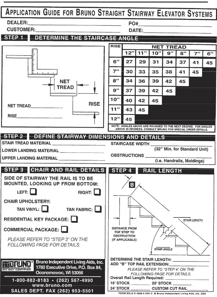
 Determine the correct length for the rail. Use Steps 2 and 4 from the APPLICATION GUIDE sent with the rail.
 Cut the BOTTOM end of the rail using a chop saw or other power metal-cutting saw.
 Drill (2) holes for mounting bumper assembly (see photo in Installation section).
 Mount the lower bumper assembly and lower end plate.
 Loosely assemble the clamp halves.
 Place the clamp assemblies on the stairs in the locations specified in the installation instructions.
NOTE: There is no clamp on the top step/landing. Consult the charts shown in the Application Guide for proper dimensions of the B top rail extension.
 Place the lower rail section in the clamps and tighten clamps enough to hold the section immobile. Do not fully tighten at this time.
 Place the upper rail section in the clamps. Make sure the upper and lower sections mount flush.
 Tighten the clamps enough to hold the section immobile. Do not fully tighten at this time.
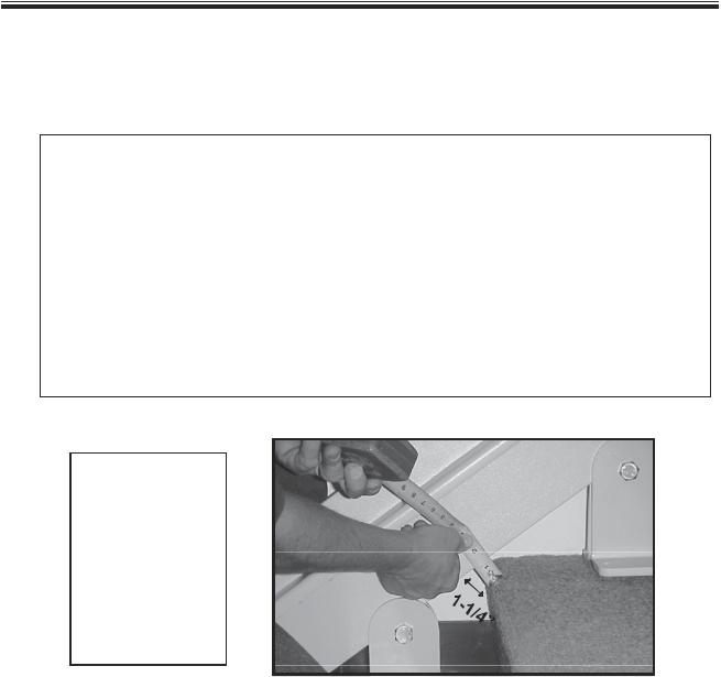
 Check the rail-to-step nose clearance: MUST BE AT LEAST 1-1/4 IN.
SRE-2000 RES UL 08-16-2004 |
9 |
©2004,2001 BRUNO INDEPENDENT LIVING AIDS, INC.® |
OVERVIEW (CON T.)
Rail sections MUST be vertical, or must lean slightly toward the back.
Rail must NEVER LEAN FORWARD.
 Secure the clamps to the stairs.
 Verify that the upper and lower rail sections are straight and level.
 Feed the charge harness into the channel on the back of the rail section.
 Mount the carriage assembly.
 Adjust the carriage angle by loosening the (2) adjustment bolts.
 Secure the footrest to the carriage.
 Install the seat assembly between the footrest mounting plate and the seat lever.
 Install the upper bumper assembly.
 Route wire to household outlet.
Test unit for proper and safe operation.
 Train customer in safe operation of the Stairway Elevator.
REMEMBER:
No installation is comlete until the customer has been instructed in the safe use of the Electra-RideTM Elite Stairway Elevator. After demonstrating correct operation, have the customer operate the elevator several times while you are available to answer questions. BE SURE THE CUSTOMER UNDERSTANDS ALL SAFETY ASPECTS OF USING THE ELEVATOR. Patience and thoroughness in this phase of the installation are often rewarded with repeat business and customer referrals.
©2004,2001 BRUNO INDEPENDENT LIVING AIDS, INC.® |
10 |
SRE-2000 RES UL 08-16-2004 |
INSTALLATION
Fitting the rail
1.Determine whether the stairway elevator will be installed on the right or left side of the stairs, as viewed from the bottom of the stairs.
NOTE: Unless otherwise specified, Bruno Stairway Elevators are shipped from the
 If you wish to convert to right-side installation, please refer to the instructions appearing later in this manual.
2.Determine the exact rail length by placing a tape measure in a straight line on the stairs (see STEP 2 in the APPLICATION GUIDE). To this number, add Measurement B (see STEP 4 in the APPLICATION GUIDE).
NOTE: If the unit is equipped with an overspeed brake, add 5 to the rail length.
This calculation will allow you to precisely fit the Stairway Elevator to your customer by determining the most comfortable seat-to-floor height within the space available at the top of the stairs.
3. Mark the length on the rail, as determined in the previous step.
NOTE: Be sure that excess length is cut off of the LOWER end of the rail.
4.After marking, and BEFORE cutting the rail, cut the cable channel back approx. 3 inches from the mark to avoid having to cut through the channel.
CUT OFF EXCESS FROM
BOTTOM END OF RAIL
SRE-2000 RES UL 08-16-2004 |
11 |
©2004,2001 BRUNO INDEPENDENT LIVING AIDS, INC.® |
INSTALLATION
©2004,2001 BRUNO INDEPENDENT LIVING AIDS, INC.® |
12 |
SRE-2000 RES UL 08-16-2004 |

INSTALLATION
INSTALLATION
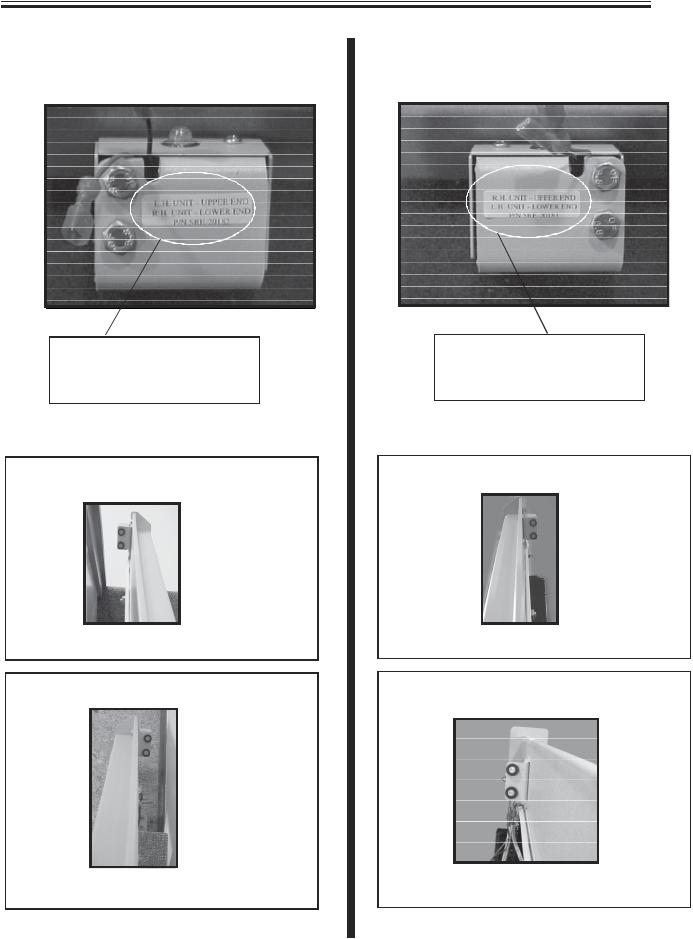
Distinguishing leftand right-hand charge bumper brackets
LEFT-HAND INSTALLATION |
RIGHT-HAND INSTALLATION |
SRE-20286
|
SRE-20287 |
L.H. UNIT - UPPER END |
R.H. UNIT - UPPER END |
R.H. UNIT - LOWER END |
L.H. UNIT - LOWER END |
Left-hand installations: |
Right-hand installations: |
bracket SRE-20286 mounts on upper end |
bracket SRE-20287 mounts on upper end |
charge contacts point down the stairs |
charge contacts point down the stairs |
bracket SRE-20287 mounts on lower end |
bracket SRE-20286 mounts on lower end |
charge contacts point up the stairs |
charge contacts point up the stairs |
©2004,2001 BRUNO INDEPENDENT LIVING AIDS, INC.® |
14 |
SRE-2000 RES UL 08-16-2004 |

INSTALLATION
Cutting the rail and installing the lower bumper
IMPORTANT NOTE!
Under no circumstances should a rail section be cut shorter than 18 in. (46 cm).
There must be at least (2) clamps on a short rail section (1 at the rail joint and 1 at the rail end). Cutting a rail shorter than 18 in. (46 cm) would not allow enough room for the (2) necessary clamps. Example:
After measuring the staircase, you determine you need 9 feet of rail. With your (2) 8-foot sections you decide to use (1) 8-foot section and cut the remaining (1) foot from the second 8-foot section. Doing this could yield a rail piece with insufficient weld.
Instead, Bruno recommends cutting at least one foot off one of the 8- foot sections (leaving 7 feet of rail) and then cutting 2 feet from the second 8-foot section. You will have a (1) 7-foot section and (1) 2-foot section, both of which are long enough to be properly mounted (2 clamps minimum per short rail).
NEVER CUT OFF THE JOINT END!
The M6 bolts securing the gear rack must remain intact.
Cut off the end with the pre-drilled charge contact mounting holes.
Then, using the provided template, redrill (2) holes on each end of the rail.
SRE-2000 RES UL 08-16-2004 |
15 |
©2004,2001 BRUNO INDEPENDENT LIVING AIDS, INC.® |
INSTALLATION
Cutting the rail and installing the lower bumper (con t.)
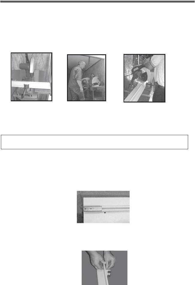
1.BE SURE TO WEAR PROTECTIVE GLOVES AND EYEWEAR. During the cutting process, sparks will fly and the metal rail will become very hot.
2.Place flat side of the rail on the saw bed. Carefully align the saw to the line marking the desired finished length of the rail.
flat side of rail to saw bed |
align saw with mark |
up and down motion |
3.For a precise and efficient cut, Bruno recommends the use of a chop saw*. A down-up motion during the cutting process helps avoid overheating the saw motor.
*This chop saw (or other power saw) must be equipped with metal-cutting blade suitable for aluminum and steel.
4.Once the rail is cut, deburr the cut end using a file or other appropriate tool. Soften any sharp edges which might abrade the insulation of the wiring routed to the bumper at the rail end.
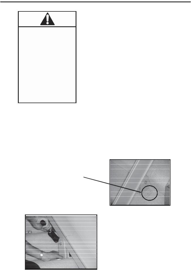
5.Place the metal template (provided - see Box B of Carton 2) on rail as shown. Hold in place. Using a 1/8 in. bit, drill two pilot holes. Switch to a 5/16 in. bit and re-drill the (2) holes.
(normally black, template has been lightened for illustration purposes)
template on rail
6.Install the lower bumper assembly and end cap using the hardware provided. You may wish to place a piece of cardboard or a non-skid rug under the end of the bottom rail to protect the floor and to keep the rail section from sliding off the stairs.
©2004,2001 BRUNO INDEPENDENT LIVING AIDS, INC.® |
16 |
SRE-2000 RES UL 08-16-2004 |

INSTALLATION
Placing the rail clamps and rail sections
two at the bottom
two in the middle (one on each side of rail joint)
two at the top*
1. Place rail clamps on the stairs in the following pattern (LONGER-footed clamp to the outside).
 bottom landing
 first tread up from bottom landing
 top landing
 first tread down from top landing*
(NO CLAMP ON TOP STEP/LANDING FOR UNIT WITH STANDARD EXTENSION)
 closest tread above and below rail joint(s), then
  minimum of every third tread over the remainder of the staircase.
2.Mount the bottom rail section in between the clamp halves. Tighten the hardware enough to render the rail immobile. Do not fully tighten at this time.
3.Once the bottom rail section is mounted in the clamp assemblies, rest the bottom of the rail against the step noses at a distance from the wall of approx. 6 in.
*A minimum of (1) clamp must be installed beneath the B LOCK CLAMP (secured to the floor or step).
After the rail is installed, drill through rail (using holes in top of B clamp as guides) with a 1/4 in. bit.
Install M6 hardware, with nut on wall side of rail (see exploded view at rear of manual).
B LOCK CLAMP.
NOTE:
Insert the hardware so that the nut is closest to the wall.
SRE-2000 RES UL 08-16-2004 |
17 |
©2004,2001 BRUNO INDEPENDENT LIVING AIDS, INC.® |

INSTALLATION
4.Place the upper section of the rail in the clamps placed in Step 1. When the rail is inserted between the clamp halves, it will rest on the clamp spacer (see illustration,
previous page).
slightly loosen x 5
5.Slightly loosen the (3) M8 hex head screws and the (2) M6 Allen head screws securing the joint plate to the rail.
This makes it easier to align the screws and the holes on the mating rail section.
6.Gently slide the upper rail section up or down the stairs until it mates with the lower section so that the mating ends fit flush.
7.From the kit provided, insert the (2) M6x1x45 mm Allen head and the (3) M8x1.25x16 mm hex head screws into the appropriate holes in the joint plate. DO NOT TIGHTEN.
If the M6 Allen head screws do not line up with the gear rack threads, loosen all of the M5 set screws (two turns only)
to allow the gear rack to slide just slightly in the rail,
and permit alignment of the M6 screws and the gear rack threads.
8. Before tightening the hardware:
 check that the screw and rail/gear rack threads are properly engaged;
  make sure the rail sections are flush.
It may be helpful to apply a small amount of silver anti-seize material to the hardware threads before inserting.
9. Order of tightening hardware is important!
 FIRST tighten the (4) M6 Allen head screws engaging the gear rack.
 Then tighten the (6) M6 hex head screws. Tighten us first!
©2004,2001 BRUNO INDEPENDENT LIVING AIDS, INC.® |
18 |
SRE-2000 RES UL 08-16-2004 |
INSTALLATION
10.Slide the top and bottom clamps up or down on the rail until they are firmly seated on the step.
IMPORTANT NOTES
The rail must rest approximately 1-1/4 inches above the step nose of EVERY step, and extend from the floor at the bottom of the stairs to a point beyond the nose of the top step (see Application Guide Step 4).
It may be necessary to pound a scratch awl in one of the rear clamp mounting holes to prevent the rail from sliding.
Rail-to-step nose distance must
INCREASE
TO 1.5
INCHES if
EXTENDED FOOTREST ASSEMBLY is used.
STEP NOSE TO BOTTOM OF RAIL = 1-1/4 IN.
Stair profiles do vary, so it is critical to ensure proper clearance between the step nose and the bottom of the rail.
Failure to install the rail at the specified 1-1/4 in. distance from the step nose will cause the footrest to contact to steps, thus provoking intermittent operation of the stairway elevator. If necessary, gently slide rail and clamps toward or away from the stair riser to adjust the clearance to the 1-1/4 in. recommanded distance.
SRE-2000 RES UL 08-16-2004 |
19 |
©2004,2001 BRUNO INDEPENDENT LIVING AIDS, INC.® |
INSTALLATION
As you tighten the clamps around the rail sections, regularly check that the rail is vertical or leaning backwards.
Rail section MUST be at a 90-degree angle to the stairs, OR leaning BACK slightly. The rail section must NEVER lean forward.
11.Tighten the clamp hardware enough to render the upper rail immobile. Do not fully tighten at this time.
12.Once the rail sections are installed, tighten the clamps. BEFORE mounting the carriage, check the straightness of the rail over all of the stairs by using a level, or a plomb line along the rail. If the rail bows or leans forward, insert shims or readjust the clamps.
13.Secure 2 or 3 of the rail clamps to the stairs. Secure the back half of the clamps
first. The rail should be located 2-5/8 in. from the closest obstruction and the back of the rail.
BACK FOOT OF CLAMP (3 HOLES)
NOTE FOR
INSTALLATION ON CARPET
Before securing the rail clamps with hardware, seat them using a deadblow hammer. Use a rubber mallet to compress the rug and pad before anchoring the clamp to the step.
©2004,2001 BRUNO INDEPENDENT LIVING AIDS, INC.® |
20 |
SRE-2000 RES UL 08-16-2004 |
INSTALLATION
Bruno ships the Stairway Elevator with fasteners appropriate for WOODEN STAIR TREADS ONLY. Installation of the Stairway Elevator on surfaces made of materials other than wood may require different fasteners specific to the material. If you are unsure as to which fastener applies to the installation, please contact Bruno at 1-800- 882-8768.
IMPORTANT MEASUREMENT:
TAKE BEFORE AND AFTER SECURING EACH CLAMP:
DISTANCE
BETWEEN BACK OF RAIL
AND
THE CLOSEST OBSTRUCTION (for example, WALL, RAILING,LIP OF
BANNISTER, WINDOWSILL, HANDRAIL)
MUST BE AT LEAST 2-5/8 IN.
2-5/8 IN. FROM
CLOSEST OBSTRUCTION
14.For installation on hardwood stairs, Bruno recommends drilling a pilot hole for the clamp fastener before inserting the fastener.
15.Do not secure the remaining clamps until the carriage is on the rail, and all clearances are verified.
SRE-2000 RES UL 08-16-2004 |
21 |
©2004,2001 BRUNO INDEPENDENT LIVING AIDS, INC.® |
INSTALLATION
Routing the cable
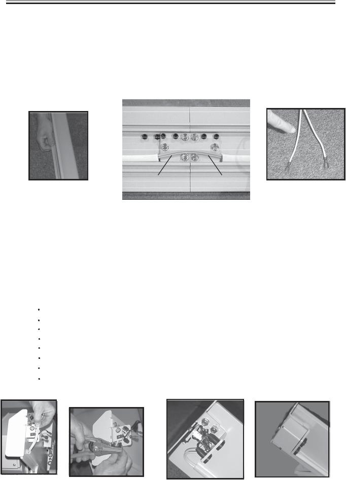
Once the clamps are in place, and secure, and after verifying that the rail bottom is at least 1-1/4 in. from the bottom of the rail, and that the rail is straight, insert the power cable into the channel that runs along the back of the rail (side closest to the wall). Determine the location of the wall outlet. Start inserting the cable (i.e., pigtail of the charge harness) at the end (top or bottom) closest to that outlet. Be sure to position the battery charger at this end. When routing the cable around the joint plate, make sure that the cable rests snugly flat against the rail.
routing the cable |
cable flat against rail |
smooth to |
rib to |
||
|
red (+) |
black (-) |
|
female |
male |
Notice that the end of the cable opposite the pigtail harness has been split slightly, and includes one male and one female connector.The sheathing of one lead is ribbed (finger is pointing to ribbed sheathing). The other lead s sheathing is smooth.
The ribbed lead attaches, via FEMALE connector, to the RED positive charge lead. The smooth lead attaches, via the MALE connector, to the BLACK negative charge lead.
Increase the split |
|
|
|
Cut off approximately the length shown below. |
|
||
Discard |
the old connectors. |
|
|
Strip the freshly cut wire ends. |
|
|
|
Install the new connectors provided in the kit. |
|
||
Connect the two wires to the charger bracket. |
|
||
Gently tuck the wires in the bumper assembly. |
|
||
Attach the bumper cover. |
tuck wires into |
|
|
cut to length |
|
|
|
|
bumper assembly |
attach bumper cover |
|
strip wire ends |
|
|
|
©2004,2001 BRUNO INDEPENDENT LIVING AIDS, INC.® |
22 |
SRE-2000 RES UL 08-16-2004 |
INSTALLATION
Mounting the carriage, upper bumper and upper end cap
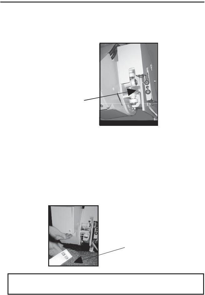
Lift and tilt the carriage as you guide the carriage wheels onto the rail. The newlydesigned rail features a recessed gear rack to facilitate feeding the carriage onto the rail.
RECESSED GEAR
RACK FOR EASIER
MOUNTING OF CARRIAGE
ONTO RAIL
Turn on the circuit breaker. Once you feel the carriage begin to engage the gear rack, USE THE REMOTE to finish feeding the carriage onto the rail.
Make sure the remote is pointed at the sensor.
The remote will feed the carriage smoothly onto the rail , and at the proper speed to ensure that the gear rack and carriage mesh correctly.
sensor 

USE THE REMOTE TO FULLY
ENGAGE THE CARRIAGE ON
THE GEAR RACK
****MOUNT THE UPPER BUMPER ASSEMBLY AND THE UPPER END CAP.****
SRE-2000 RES UL 08-16-2004 |
23 |
©2004,2001 BRUNO INDEPENDENT LIVING AIDS, INC.® |
INSTALLATION
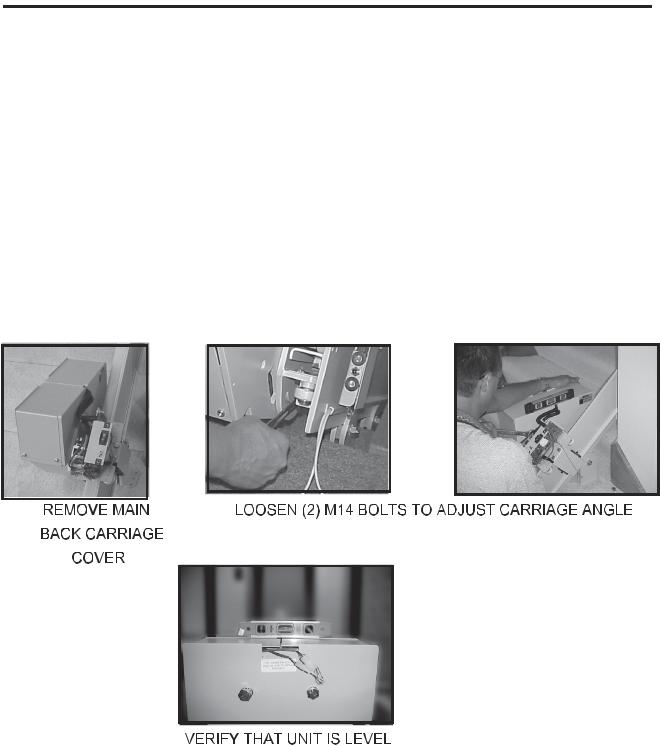
Adjusting the carriage angle
Using the remote, verify that the carriage travels smoothly down and back up the rail.
When the carriage is at the top of the stairs, check that it is level using a builder s or protractor level. To adjust the carriage angle to make the unit level, loosen the two (2) M14 bolts on the carriage subassembly with a 22mm open-ended wrench. To access the second bolt, remove the back main carriage cover. Gently apply downward pressure on the right or left side of the carriage, as needed to return the carriage to a level condition. RETIGHTEN THE 2 BOLTS. Recheck with the level.
Checking the wall clearance
Now that the carriage is securely mounted on the rail, check the clearance between the antenna and the closest obstruction (wall, handrail, windowsill, base of railing).
©2004,2001 BRUNO INDEPENDENT LIVING AIDS, INC.® |
24 |
SRE-2000 RES UL 08-16-2004 |
INSTALLATION
Mounting the footrest assembly
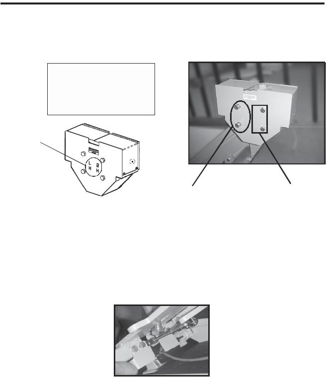
Note on carriage plate:
Longer M14 bolts must be used to install footrest
L R
H H
LH and RH are burned
into the carriage plate to indicate correct location of longer bolts for footrest installation
longer bolts here for |
longer bolts here for |
left-hand installation |
right-hand installation |
Longer M14 bolts must be used to install the footrest. The extra length is needed to accommodate the plate thickness. For left-hand installations, the longer bolts are in the holes closest to the LH. For right-hand installations, the longer bolts are in the holes closest to the RH.
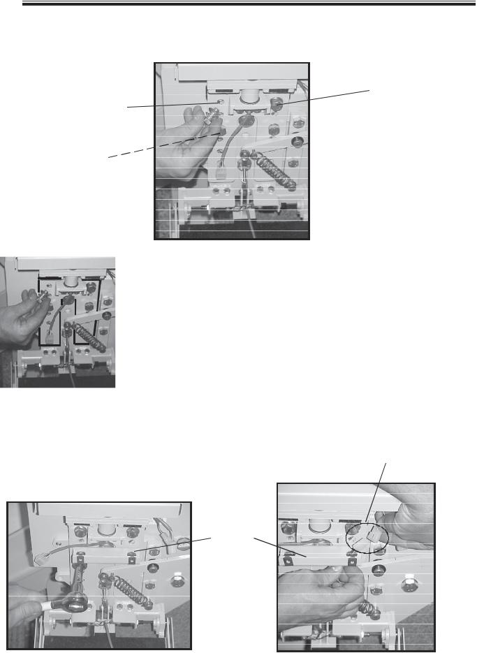
 Unscrew the two (2) longer M14 x 25 mm bolts illustrated above.
 Insert the bottom M14 bolt in the footrest support plate. For ease of bolt insertion in the footrest slot, tip the footrest assembly in its folded position (see photo).
 Insert the top M14 bolt in the footrest support plate.
NOTE: There are (2) holes above the slotted opening. Inserting the M14 bolt in the
UPPER hole positions the footrest about 3-1/2 above the floor. Inserting the bolt in the LOWER hole positions the footrest about 5 above the floor.
 Tighten the two (2) bolts.
SRE-2000 RES UL 08-16-2004 |
25 |
©2004,2001 BRUNO INDEPENDENT LIVING AIDS, INC.® |
INSTALLATION
Mounting the seat assembly
upper
upper
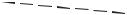 lower
lower
lower
seat post assembly outlined in black for illustration purposes
1.Slide the seat post assembly between the footrest assembly mounting plate and the footrest lever.
2.Secure the seat post assembly:
 UPPER HOLES: Secure with two (2) M10 x 1.50 x 20mm lg hex head cap screws, (2) flat washers and (2) lockwashers.
 LOWER HOLES: Install the front cover mount with two
(2) M10 x 1.50 x 20 mm lg head head cap screws and
(2)lockwashers (no flat washers).
3.Route the wire harness of the carriage contact assembly through the front cover mount as shown.
4.Connect the two ends of the wire harness.
connect wiring harness
FRONT
COVER
MOUNT
©2004,2001 BRUNO INDEPENDENT LIVING AIDS, INC.® |
26 |
SRE-2000 RES UL 08-16-2004 |
INSTALLATION
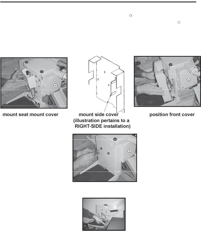
5.Mount the seat mount cover using the pre-attached VelcroR strips.
6.Mount the side cover to cover the unused opening, using the pre-attached VelcroR strips (cover the hole on the right for left-side installations, and the hole on the left for right-side installations).
7.Position the front cover as shown below and secure with the black bumpers and #8 x .75 in. lg Phillips head sheet metal screws.
secure front cover
8.RUN THE CARRIAGE UP AND DOWN THE RAIL TO VERIFY ALL CLEARANCES.
9.Finish mounting and securing all rail clamps.
SEAT HEIGHT ADJUSTMENT
Remove all (4) M10 x 20mm bolts. Slide the seat up or down. Line up the holes on the seat post with the holes on the footrest mounting plate at the desired height. Reinsert the M10 x 20 mm bolts and corresponding washers. Tighten.
SRE-2000 RES UL 08-16-2004 |
27 |
©2004,2001 BRUNO INDEPENDENT LIVING AIDS, INC.® |
INSTALLATION
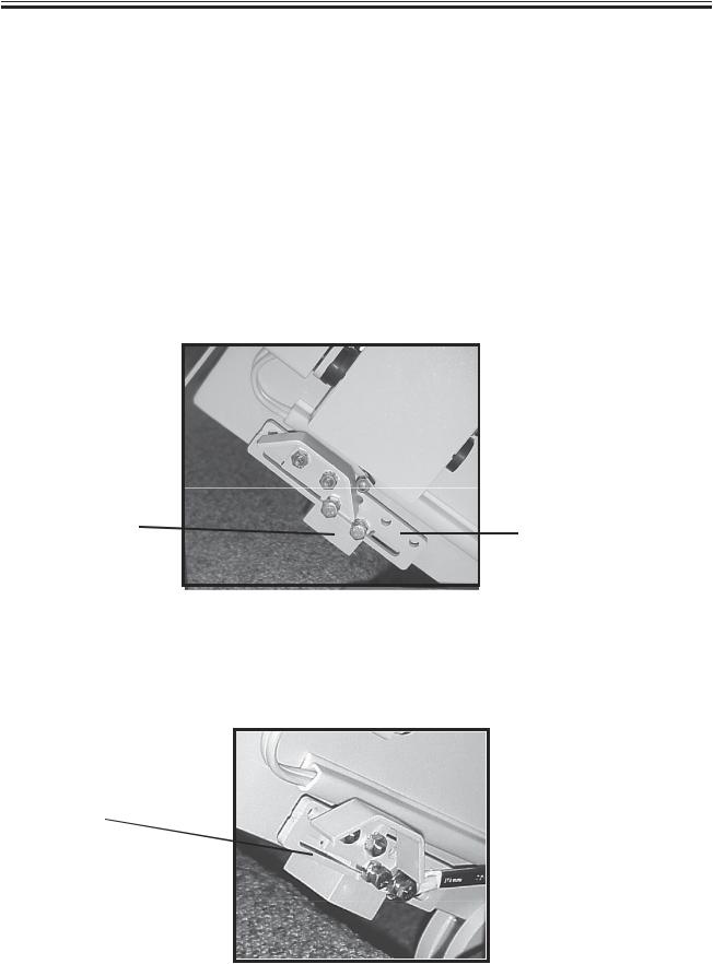
Mounting the final limit ramp kit
The final limit ramp kit is a safety feature which enhances the stopping capability of the Electra-RideTM Elite. It mounts on the top rail section, on the side facing away from the stairs.
Before installing the final limit ramp kit, run the carriage down a foot or two to provide greater access to the mounting hardware.
Mount the final limit ramp kit on the bottom side of the rail as shown below.
FINAL LIMIT |
FINAL LIMIT |
|
ADJUSTMENT BAR |
||
ADJUSTMENT |
||
BLOCK |
|
Using the holes for the ramp and/or the slotted adjustment bar and block allows for fine adjustment of the position of the final limit ramp kit in relation to the clamp on the top step.
ADJUSTMENT
SLOT
To attach the block to the rail, tighten the (2) M6x1x30mm bolts ONLY.
To secure the adjustment bar, tighten the (2) M6 nuts on the M6x1x30mm bolts.
©2004,2001 BRUNO INDEPENDENT LIVING AIDS, INC.® |
28 |
SRE-2000 RES UL 08-16-2004 |
 Loading...