

Page 1
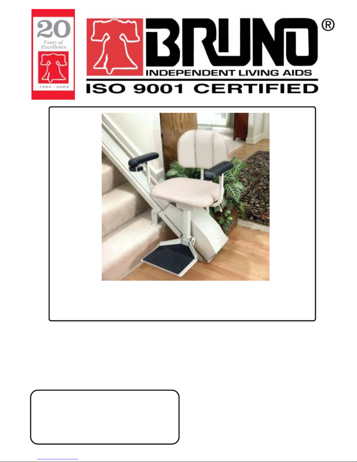
SRE-2700
ELECTRA-RIDE™ LT
STAIRWAY ELEVATOR
1780 EXECUTIVE DR., P.O., BOX 84, OCONOMOWOC, WI 53066 USA
TEL.: (262) 567-4990 FAX: (262) 953-5501
Bruno invites your calls at:
Technical Service
Technical Service fax: 262-953-5503
DEALER:
1-800-882-8183
Toll free number valid throughout the U.S. and Canada
email: service@bruno.com
www.bruno.com
INSTALLATION MANUAL
MAN-2700
REVISED 06-11-2004
Page 2

IMPORTANT NOTES
This stairway elevator is intended
for indoor use only
in a heated, enclosed location
above 35° F (2° C).
NOTE
The warranty for the Electra-Ride™ LT
Stairway Elevator is
rendered null and void
if the unit is installed by
anyone other than an authorized Bruno dealer.
Electra-Ride™ is a trademark of Bruno Independent Living Aids, Inc.®
©2004,2002 BRUNO INDEPENDENT LIVING AIDS, INC.®
2
SRE-2700 06-11-2004
Page 3

TABLE OF CONTENTS
IMPORTANT NOTES................................................................................... 2
INTRODUCTION.......................................................................................... 4
TECHNICAL SPECIFICATIONS.................................................................. 5
CARTON CONTENTS................................................................................. 6
OVERVIEW.................................................................................................. 7-8
INSTALLATION .......................................................................................... 9-30
Tools Necessary for Installation................................... 9
Bumper Bracket Installation......................................... 10
Fitting the Rail.............................................................. 10
Application Guide......................................................... 11-12
Cutting the Rail............................................................. 13
Rail Joint Assembly...................................................... 14
Positioning Foot Clamp Assemblies............................. 15-17
Mounting the Carriage on the Upper Rail..................... 18-19
Adjusting the Carriage Angle........................................20
Installing the Seat Assembly........................................ 20-22
Installing the Final Limit Ramp and Switch.................. 22
Connecting the Power Source..................................... 23-24
Testing the Unit............................................................ 25
Infrared Call/Send Transmitter..................................... 26
Mounting the Standard Call/Send Transmitter............. 27
Learning the Standard Call/Send Transmitter.............. 28-29
When the Installation is Complete............................... 29
Lubrication................................................................... 30
ELECTRICAL............................................................................................... 31-34
Converting Rail/Carriage for Right-Hand Operation..... 31
Converting Rocker Switch to Left Armrest................... 32
Circuit Breaker............................................................. 33
Wiring Schematic......................................................... 34
LONG-TERM STORAGE............................................................................. 35
TROUBLESHOOTING................................................................................. 36-37
YEARLY MAINTENANCE OPERATIONS................................................... 38
EXPLODED VIEW AND BILL OF MATERIALS.......................................... 39-56
LIMITED WARRANTY................................................................................. 57
SRE-2700 06-11-2004
3
©2004,2002 BRUNO INDEPENDENT LIVING AIDS, INC.®
Page 4

INTRODUCTION
Thank you for purchasing an SRE-2700 Electra-Ride™ LT Stairway Elevator. Be sure to
check carton contents for shipping damage as soon as they are received.
Also, check the carton contents against the packing list before leaving the shop to install
product on site.
Report any discrepancies to Bruno Independent Living Aids immediately.
Bruno encourages you to read through the installation manual before installing the Stairway
Elevator. Doing so will help you install the elevator more quickly and avoid the frustration of
getting to the job site only to discover that you are missing a critical tool or piece of equipment.
MATERIAL DATA SAFETY SHEET(S) ON
MATERIALS USED ON THIS UNIT CAN BE
REQUESTED THROUGH OUR TECHNICAL SERVICE
©2004,2002 BRUNO INDEPENDENT LIVING AIDS, INC.®
NOTE:
DEPARTMENT
4
SRE-2700 06-11-2004
Page 5

SPECIFICATIONS
Technical Specifications
Weight Capacity 275 lbs. (125 kg)
Speed 18 - 23 fpm (5.5-7.0 m/mn)
Power Source two (2) 12-volt sealed, maintenance-free
batteries with 24-volt continuous-duty
charger
Motor 24 VDC, 2-pole, 1.32 hp
Drive self-locking gearbox, rack-and-pinion
drive
Control constant pressure (armrest and
2 transmitters)
Brake self-locking worm gear
Maximum incline 45 degrees
Rail steel channel with integral drive gear
rack
Seat Swivel 0, 45 and 90 degrees at top and bottom
Power Supply 100-240 VAC, 50/60 Hz, 0.85 amp power
supply input, 33 VDC 1-amp transformer
output, 29.6 to 27.6 VDC charging at
850 mA max., continuous monitoring.
SRE-2700 06-11-2004
5
©2004,2002 BRUNO INDEPENDENT LIVING AIDS, INC.®
Page 6
PACKING LIST
CARTON CONTENTS
The ELECTRA-RIDE™ LT is shipped in 4 cartons. Check the
contents of the cartons to be sure you have all of the components
before beginning an installation.
CHECK CARTON
CONTENTS FOR
SHIPPING DAMAGE
IMMEDIATELY UPON
RECEIPT
*MSDS (Material Safety
Data Sheet) available
from Bruno upon
request. Contact
Service
Department.
Check the carton contents for shipping damage upon receipt.
Damage claims must be filed by the dealer, not the manufacturer.
Bruno Independent Living Aids, Inc.® cannot be responsible for shipping
damage.
CARTON 1
(1) complete carriage assembly including footrest
CARTON 2
(1) complete seat assembly
(2) IR transmitters
Box A
(1) tube
(1)
final limit switch ramp assembly
(1) SRE-K-1553 bumper assembly parts kit
(2) bumper assemblies
(2) pieces of Velcro®
(10) 11" lg wire ties
(1) SRE-K-2705 electrical parts kit (16' rail)
(or SRE-K-2706 for 20' rail)
(1) custom-length charge harness
(2) transmitter mounting brackets
(2) SRE-K-2701 transmitter mounting hardware kit
(1) power supply
(1) SRE-K-1518 power supply hardware kit
Box B
(9) foot clamp sets (16' RAIL) • 11 (20' RAIL)
• TBD** (CUSTOM RAIL)
**DEPENDS UPON RAIL LENGTH
(36) sheet metal screws (M 6.3 X 50 mm)(16' rail);
QTY.44 for (20' rail)
white lithium grease per rail set
***NOTE:
Rail sections must have
matching numbers
stamped on the
sections.
©2004,2002 BRUNO INDEPENDENT LIVING AIDS, INC.®
( ) UPON REQUEST
CARTON 3
(1) rail half (upper)
CARTON 4
(1) rail half (lower)
(1) joint plate
(1) SRE-K-1502 joint plate hardware kit
CARTON 5 (OPTIONAL)
(1) rail half (lower)
(1) joint plate
(1) SRE-K-1502 joint plate hardware kit
6
clamps, adjustable, 9 lbs. ea.
SRE-2700 06-11-2004
Page 7

INSTALLATION
OVERVIEW
OVERVIEW
OVERVIEW OF INSTALLATION
Installation of the ELECTRA-RIDE™ LT Stairway Elevator consists of the following:
* Determine whether the elevator should be a left- or right-side installation. "Left"
or "right" installation is determined by the side of the stairway on which the rail is
installed (viewed from the bottom of the stairs). THE GEAR RACK WILL BE
TOWARD THE CENTER OF THE STAIRS. Unless specified otherwise, Bruno
Stairway Elevators are set up for left-side installation when shipped, but can easily
be converted to right-side installation. Instructions for converting the unit for
right-hand installation are included later in this manual.
* Identify and locate lower rail section and bumper bracket assembly.
* Assemble and tighten the rail joint. CAUTION: RAILS CANNOT BE MIXED.
CHECK ID NUMBERS STAMPED AT ENDS OF RAILS.
* Determine the correct length for the rail (using Steps 2 & 4 from the APPLICATION
GUIDE), and cut the rail.
* Install lower bumper assembly.
* Position rail on left or right side of stairway using rail clamp assemblies.
* Mount the carriage on the upper rail.
* Adjust the carriage angle by loosening the (2) Angle Adjustment Bolts.
* Install seat assembly and make electrical connections.
* When installing a right-side ELECTRA-RIDE™ LT , follow instructions for
Changing to Right-Hand Operation
* Perform a 5-6 trial runs of the ELECTRA-RIDE™ LT to determine final location of
the rail.
SRE-2700 06-11-2004
7
©2004,2002 BRUNO INDEPENDENT LIVING AIDS, INC.®
Page 8

INSTALLATION
OVERVIEW
OVERVIEW (CON'T.)
* Determine the appropriate location for the remaining mounting clamps and
brackets for attaching the rail to the stairs then loosely assemble the clamps
and brackets to the Stairway Elevator rail.
* Adjust and tighten the rail clamps and mounting brackets.
* Anchor the mounting brackets to the stairs.
* Locate and drill holes for the top bumper bracket.
* Install the top bumper bracket.
* Determine where the power supply will be positioned, and install rail wire lead
accordingly.
* Position power supply at upper or lower landing.
* Route wire to household outlet.
* Mount remote call/send transmitters.
* Test unit for proper operation.
* Train customer in safe and convenient operation of the Stairway Elevator.
REMEMBER:
No installation is complete until the customer has been trained to use the Elevator
smoothly and safely. After demonstrating correct operation, have the customer
operate the Elevator several times while you are available to answer questions.
BE SURE THE CUSTOMER UNDERSTANDS ALL SAFETY ASPECTS OF
USING THE ELEVATOR. Patience and thoroughness in this phase of the
installation are often rewarded with repeat business and customer referrals.
©2004,2002 BRUNO INDEPENDENT LIVING AIDS, INC.®
8
SRE-2700 06-11-2004
Page 9
INSTALLATION
Tools Necessary for Installation
[ ] Protractor level, builder's level
[ ] Socket set, metric (10 mm through 22 mm)
[ ] Ratchet, with 6" extension
[ ] Combination wrench set, metric (10 mm through 22 mm)
INSTALLATION
NOTE:
The standard stairway
elevator is suitable for
stairway angles up to
45 degrees.
[ ] Phillips screwdrivers
[ ] 5/16" socket (clamp screws)
[ ] 9/16" and 5/8" open-end wrench (limit switch adjustment)
[ ] 5/16" open-end wrench
[ ] Electric drill with letter `O' (.316") and 1/4" bit
[ ] Hacksaw with 2 or 3 blades, or metal cutting bandsaw
[ ] 20' tape measure
[ ] Small dead blow hammer
[ ] Rubber mallet
[ ] C-clamp
[ ] Wire crimper and stripper
[ ] Flashlight
[ ] Needle nose pliers
[ ] Scissors or knife
TIPS FOR A FASTER, SMOOTHER INSTALLATION:
• Be sure you have all necessary parts and tools before
traveling to installation site.
• Loosely assemble the foot clamp assemblies before
traveling to the installation site.
SRE-2700 06-11-2004
[ ] Extension cord
[ ] Double-sided foam tape
[ ] File
[ ] 12" adjustable wrench
[ ] 90-degree needle-nose pliers
9
©2004,2002 BRUNO INDEPENDENT LIVING AIDS, INC.®
Page 10
INSTALLATION
INSTALLATION
ASSEMBLY
1) Determine whether a left- or right-side installation is appropriate for the site. "Left" or
"right" refers to the side of the stairway on which the rail is installed (as viewed from the
bottom of the stairs). Unless otherwise specified Bruno Stairway Elevators are shipped
from the factory in the left-side configuration. Conversion to right-side installation is
easy (instructions included later in this manual ).
2) Identify and locate lower rail section appropriate to the installation (left or right).
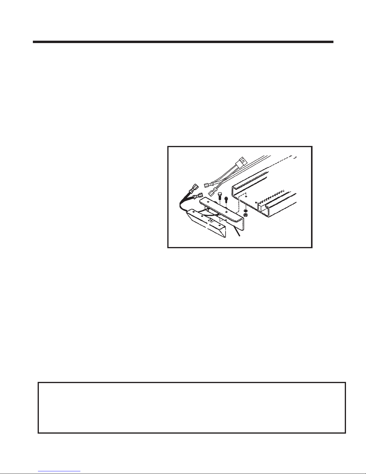
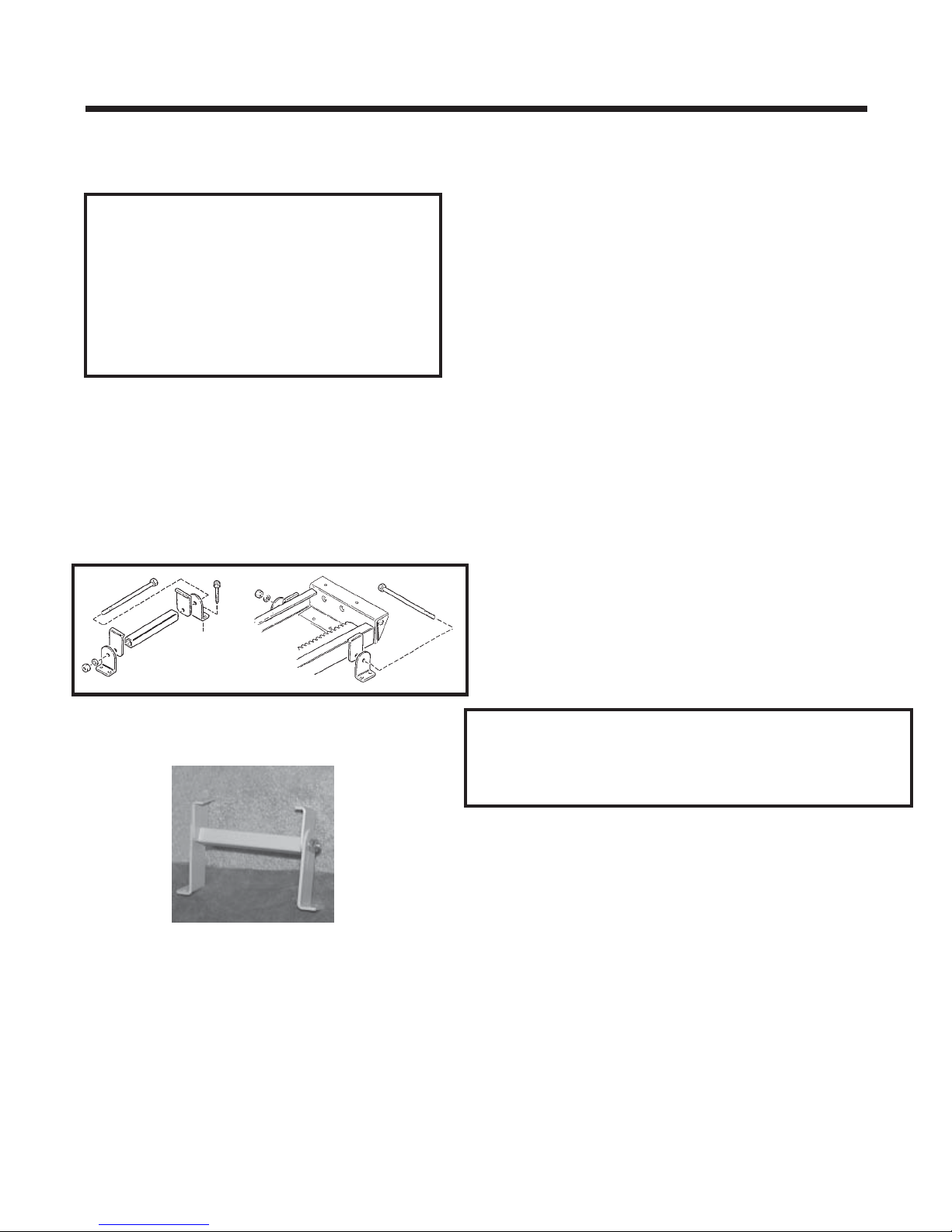
BUMPER BRACKET INSTALLATION
1) Assemble lower rail.
2) Install lower bumper bracket.
bumper bracket
FITTING THE RAIL
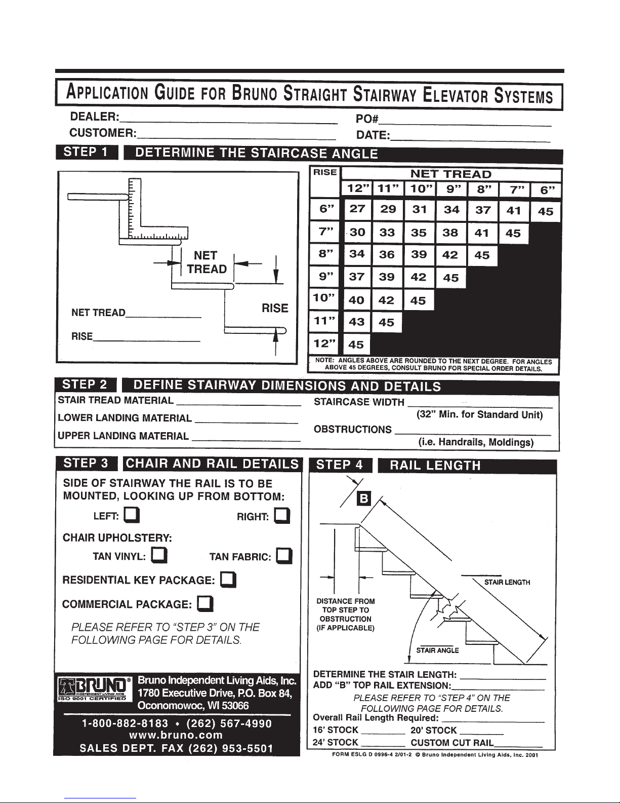
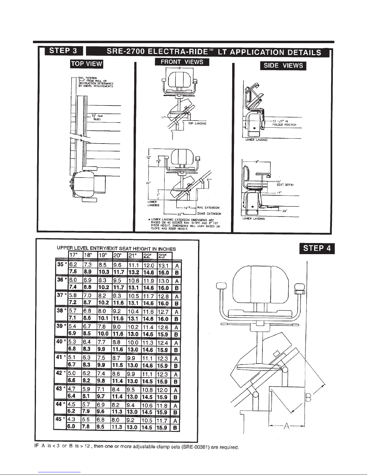
1) Determine the correct length for the rail by measuring along a straight line placed on the
stairs. (SEE STEP 2 IN THE APPLICATION GUIDE) To that amount, add Measurement B
(STEP 4 IN THE APPLICATION GUIDE). This process will allow you to custom fit the
Elevator to your customer by determining the most comfortable seat-to-floor height within
the space available at the top of the stairs.
NOTE: The rail must rest approximately 2" above the step nosing, and extend from the lower floor to a
point beyond the nosing of the top step (see Step No. 4 of the Application Guide). In some cases where
the bottom landing is made of material such as concrete, ceramic tile or slate, the last bracket on the
landing may be omitted. In this case, a bracket must be added on the second-to-last step ( bottom), and
at the top of the stairway.
REMINDER:
THIS RAIL MUST BE INSTALLED APPROXIMATELY 2" ABOVE STAIR NOSING.
OTHERWISE, FOOTREST WILL HIT THE STEPS, CAUSING INTERMITTENT
OPERATION.
©2004,2002 BRUNO INDEPENDENT LIVING AIDS, INC.®
10
SRE-2700 06-11-2004
Page 11
INSTALLATION
SRE-2700 06-11-2004
11
©2004,2002 BRUNO INDEPENDENT LIVING AIDS, INC.®
Page 12
INSTALLATION
©2004,2002 BRUNO INDEPENDENT LIVING AIDS, INC.®
12
SRE-2700 06-11-2004
Page 13

INSTALLATION
INSTALLATION
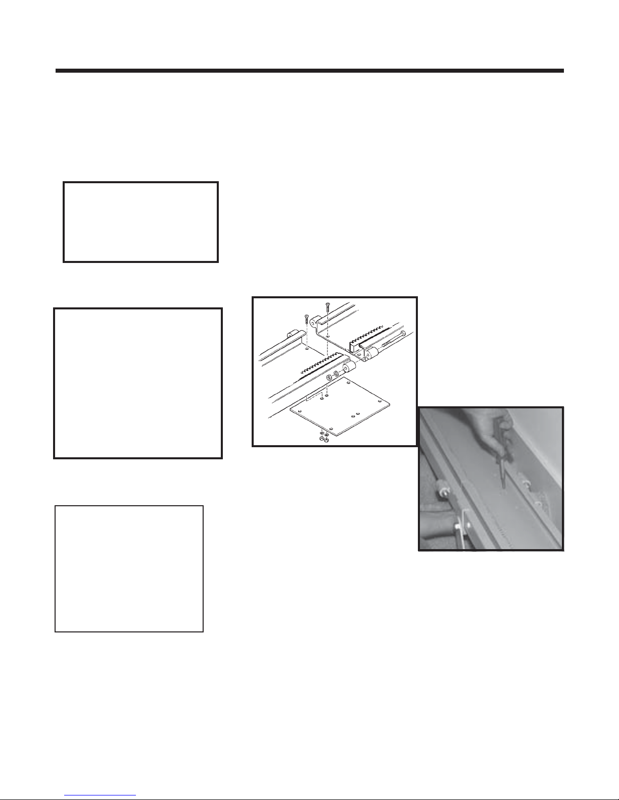
CUTTING THE RAIL
IMPORTANT NOTE!
Under no circumstances should a rail section be cut shorter than
18” (46 cm).
There must be at least (2) clamps on a short rail section (1 at the rail
joint and 1 at the rail end). Cutting a rail shorter than 18” (46 cm)
would not allow enough room for the (2) necessary clamps.
Example:
After measuring the staircase, you determine you need 9 feet of rail.
With your (2) 8-foot sections you decide to use (1) 8-foot section and
cut the remaining (1) foot from the second 8-foot section. Doing this
could yield a rail piece with insufficient weld.
Instead, Bruno recommends cutting at least one foot off one of the
8-foot sections (leaving 7 feet of rail) and then cutting 2 feet from the
second 8-foot section. You will have a (1) 7-foot section and (1) 2-foot
section, both of which are long enough to be properly mounted
(2 clamps minimum per short rail).
NEVER CUT OFF THE JOINT END!
The M6 bolts securing the gear rack must remain intact.
Cut off the end with the pre-drilled charge contact mounting holes.
Then, using the provided template, redrill (2) holes on each end of the rail.
1) Use a metal-cutting power saw or manual
hacksaw to cut the rail to length. Cut off
the end of the rail to be located at the top of the
stairway.
2) Use a file or other appropriate tool to deburr the
cut end of the rail. Soften any sharp edges
which might abrade the insulation of the wiring to
be routed to the bumper at the end of the rail.
use “O” size drill bit
(8.03mm/.316")
SRE-2700 06-11-2004
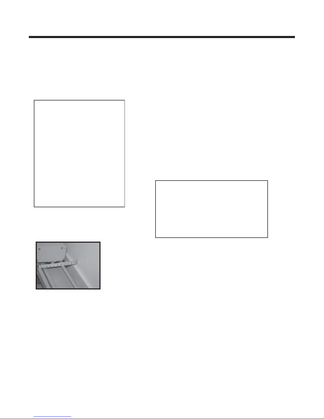
3) Use a C-clamp to hold the upper bumper bracket in
place at the cut end of the rail. Use the holes in
the bumper bracket as guides to drill mounting
holes in the rail using an“O” size (8.03 mm/.316")
drill bit.
13
©2004,2002 BRUNO INDEPENDENT LIVING AIDS, INC.®
Page 14
INSTALLATION
RAIL JOINT ASSEMBLY
NOTE:
The rail is always installed
with the gear rack towards the
center of the stairs and gear
teeth facing the wall.
INSTALLATION
SUGGESTION
1) Assemble the rail joint by attaching the bottom plate to
the rail with the screws, lock washers and hex nuts
provided with the unit. Install the bolts, internal-tooth
washers and hex nuts through the joint blocks on both
sides of the rail. Tighten all bolts securely and make sure
screw heads are flush with the surface of the inside of the
rail. PLEASE REFER TO EXPLODED VIEWS AT
BACK OF MANUAL.
Once two sections of rail
are installed, and before
installing the carriage, run a
plomb line along the rail. If
the rail bows, insert shims
or readjust clamps.
NOTE:
The chamfered
edges of the
holes must face
"up" toward
the bottom of
the rail.
©2004,2002 BRUNO INDEPENDENT LIVING AIDS, INC.®
14
SRE-2700 06-11-2004
Page 15
POSITIONING FOOT CLAMP ASSEMBLIES
1) Place rail mounting foot clamps in the
pattern as indicated.
clamp placement order
INSTALLATION
Be sure to leave a minimum space of 4"*,
as measured from the back edge of the
rail to the wall.
•bottom landing
•first tread up from bottom
landing
•top landing
•first tread down from top
landing
•closest tread above and
below the rail joint(s)
•minimum of every third
tread over remainder
of staircase.
*The 4" clearance is needed if the seat is
to swivel 90 degrees. For installations
where the seat will swivel less than
90 degrees, the rail-to-wall clearance
may be reduced to between 3" and
3-1/2". Frequently check the seat-wall
clearance during installation.
Note: If top or bottom clamp is omitted
because the landing is cement or
ceramic tile, or in the event that the
owner wishes not to drill holes in the
landing, a set of clamps should be
added on the second-to-last step and at
the top of stairway.
4" as measured from
back edge of rail to wall.
SRE-2700 06-11-2004
15
©2004,2002 BRUNO INDEPENDENT LIVING AIDS, INC.®
Page 16
INSTALLATION
INSTALLATION ON CARPET
Before securing the foot clamp
assemblies with hardware, seat them
using a deadblow hammer. Use a
rubber mallet to compress the rug and
pad before anchoring the clamp.
2) For ease of installation, finger tighten all
clamp assemblies to rail. The clamp
assembly should be positioned so the nut
is closest to the wall.
3) Slide top and bottom clamps down on the rail
until firmly seated on step. When installing on
carpeted stairs, use a rubber mallet on the
clamps to compress carpet and pad before
anchoring to steps.
4) Drill in one screw in the foot nearest the wall
of each of the top and bottom of foot of clamp
assemblies.
This will enable the installer to change the
position of the rail if necessary and minimize
the number of holes drilled in the wrong location.
©2004,2002 BRUNO INDEPENDENT LIVING AIDS, INC.®
Bruno recommends installing the screws in the
back clamp (the one closer to the wall) first,
then the screws in the front of the clamp.
16
SRE-2700 06-11-2004
Page 17
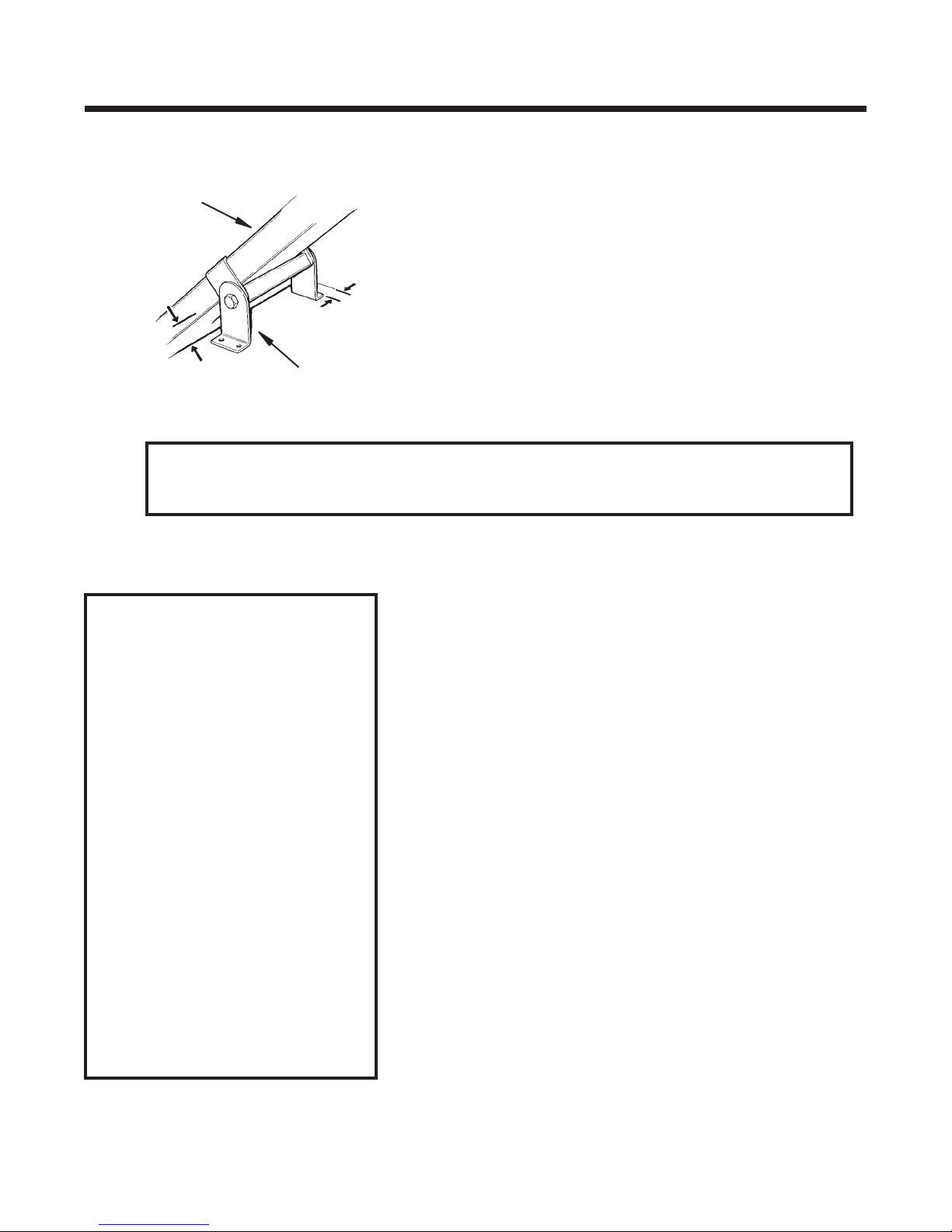
INSTALLATION
INSTALLATION
rail
approx.
2" above
nosing
foot clamp assembly
*Install foot clamps at least 2-1/2” from wall (approx. 4" between the back
edge of the rail and the wall). Provide additional foot clamp-to-wall
clearance if seat needs to swivel against wall.
INSTALLATION NOTES
For installations on hardwood
stairs, Bruno recommends
drilling a pilot hole before
inserting fasteners.
5) Frequently check the measurements at the key
locations indicated to ensure proper positioning
of the clamp assemblies.
*see note below
If threaded fastener
extends below a stair
tread that is exposed, it
can be trimmed flush
with pliers.
Bruno ships the Stairway
Elevator with fasteners
appropriate for
wooden stair treads only.
Other stair material may
require different fasteners.
Please contact Bruno
Independent Living Aids, Inc.
for information.
SRE-2700 06-11-2004
17
©2004,2002 BRUNO INDEPENDENT LIVING AIDS, INC.®
Page 18
INSTALLATION
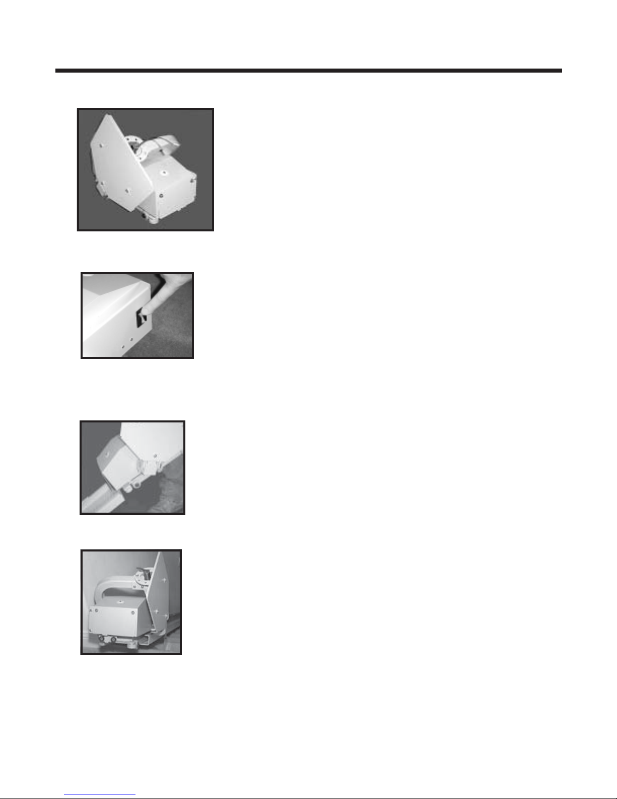
MOUNTING CARRIAGE ON UPPER RAIL
1) Remove the carriage from the shipping carton.
2) Make sure circuit breaker is OFF.
circuit breaker off
sliding carriage on rail
3) Manually slide the carriage onto the rail until
approximately half of the carriage is on the rail.
4) Manually turn the motor pulley to fully engage the
entire carriage onto the rail.
©2004,2002 BRUNO INDEPENDENT LIVING AIDS, INC.®
18
SRE-2700 06-11-2004
Page 19

INSTALLATION
5) To ensure that the carriage remains in the appropriate
position on the rail while completing the installation,
mount the upper rail bumper. Use the M8 x 1.25 x
20 mm hex head cap screws and a 13 mm wrench.
carriage on rail
Before tightening the brackets,
check to make sure that the
bumper wires are not trapped
under the bumper bracket at the
lower landing.
SRE-2700 06-11-2004
19
©2004,2002 BRUNO INDEPENDENT LIVING AIDS, INC.®
Page 20

INSTALLATION
INSTALLATION
ADJUSTING THE CARRIAGE ANGLE
1) Fold down the footrest
.
2) With the footrest folded down, LOOSEN BUT DO NOT
REMOVE the (2) M14 x 2 x 70mm hex head cap screws
using a 22 mm wrench.
3) Place a level on the footrest.
4) Pivot the seat support tube forward or backward
as necessary to level the footrest.
5) While holding the seat support tube steady, tighten
the (2) screws loosened in Step 9 to a torque of 80 ft. lbs.
REMINDER:
Recheck with level after tightening
adjustment bolts.
INSTALLING THE SEAT ASSEMBLY
1) Make sure the rocker switch and seat safety switch wires
are tucked into the seat swivel tube.
©2004,2002 BRUNO INDEPENDENT LIVING AIDS, INC.®
2) Clip the shipping tie securing the swivel cover assembly.
20
SRE-2700 06-11-2004
Page 21

INSTALLATION
INSTALLING THE SEAT ASSEMBLY (con't.)
3) Using a Phillips head screwdriver, remove the
(2) cylinder bumpers and (4) screws securing the
swivel cover.
INSTALLATION
INSTALLATION
• footrest down
• seat cushion folded up
• lift up swivel lever
• slide seat post over
wires and tube
4) Put the swivel cover to the side.
MAKE SURE FOOTREST IS DOWN!
5) With the SEAT FOLDED UP and while LIFTING UP
THE SWIVEL LEVER, slide seat post over the wires
and onto the seat support tube.
6) To make sure the seat assembly is completely
seated on the support tube, rotate the seat
assembly back and forth while gently pushing
the seat post down onto the tube.
SRE-2700 06-11-2004
21
©2004,2002 BRUNO INDEPENDENT LIVING AIDS, INC.®
Page 22

INSTALLATION
INSTALLATION
INSTALLING THE SEAT ASSEMBLY (con't.)
7) Connect the rocker switch lead first.
8) Pick up the swivel cover.
9) Plug in the seat safety switch.
10) Insert (1) wire tie through the hole in the swivel
stop as shown.
11) Tighten this wire tie around the wire harness (see
illustration to left).
12) Insert a second wire tie through the anchor as shown.
13) Tighten this second wire tie around the wire harness.
ramp just touches the roller
carriage against upper bumper
14) Trim the wire ties.
15) Tuck the wires to route them away from the spring and
seat safety switch to avoid pinching.
16) Make sure the spring sits in the opening of the swivel
switch actuator.
17) Remount the swivel cover.
18) Using a Phillips head screwdriver, insert and tighten
the (2) cylinder bumpers and (4) screws securing the
swivel cover.
INSTALLING THE FINAL LIMIT RAMP AND SWITCH
1) Make sure the carriage is positioned against the upper
bumper.
2) Position the final limit ramp so that the down side of the
ramp just touches the roller of the final limit switch.
M6 screws
©2004,2002 BRUNO INDEPENDENT LIVING AIDS, INC.®
3) Using a 10 mm wrench, tighten the (2) M6 screws as
shown in the photo to the left.
22
SRE-2700 06-11-2004
Page 23

INSTALLATION
1) Check that:
2) Determine the location of the wall outlet for the power supply.
3) Position the power supply in a suitable permanent location
circuit breaker
near either the top or bottom end of the rail, depending on the
location of the wall outlet.
4) Place the pigtail harness end of the power cable near the
power supply.
5) Route the power cable to the end of the rail opposite the
power supply by threading it under the rail and behind the
foot clamps.
INSTALLATION
CONNECTING THE POWER SOURCE
• the circuit breaker is OFF.
• all foot clamps are in the correct position;
• the rail is straight (use a plumb line as a guide).
ribbed to red
(+) (female)
smooth to black
(-) (male)
6) Notice that the end of the cable OPPOSITE THE PIGTAIL
HARNESS has been split slightly, and includes one male
and one female connector. The sheathing of one lead is ribbed
(in photo to left, finger points to ribbed sheath). The other
lead's sheathing is smooth.
7) Now that the power cable has been routed to the end of the
rail opposite the power supply (Step 5), take that length PLUS
approx. 8". Then:
• increase the split
• cut off the excess lead
• remove and discard the existing connectors
• strip the freshly cut wire ends.
• install the new connectors (provided)
8) Connect the power source leads to the bumper charge contact
leads as shown.
9) Secure the power lead to the rear clamps (ones closest to the
wall) using the wire ties provided.
SRE-2700 06-11-2004
Be sure that this wiring is mounted securely
to avoid damage.
23
©2004,2002 BRUNO INDEPENDENT LIVING AIDS, INC.®
Page 24

INSTALLATION
INSTALLATION
power supply
ROUTING WIRE HARNESSES
CONNECTING THE POWER SOURCE (con't.)
10) Turn the circuit breaker ON.
11) Plug power supply into a grounded 120VAC wall outlet.
12) Secure the power supply with the bracket provided.
Be sure the power supply
will not pose
a tripping hazard.
13) Mount (1) remote at the top of the rail and (1) at the
bottom of the rail. (Refer to the Standard Call/Send
Transmitter section later in this manual.)
The power supply should be plugged into a household outlet at
all times.
THE ONLY EXCEPTION IS WHEN TURNING UNIT 'OFF'
(SEE LONG TERM STORAGE SECTION).
If the power supply plug and
wire will be located in an
area where the power supply
could be
accidentally unplugged,
Bruno recommends the use
of a plug lock
(available at hardware and
home improvement stores).
©2004,2002 BRUNO INDEPENDENT LIVING AIDS, INC.®
24
SRE-2700 06-11-2004
Page 25

INSTALLATION NOTES
INSTALLATION
TESTING THE UNIT
1) Before securing, all clamps and with the seat in the central
riding position, use the rocker switch to run carriage/seat
assembly completely down and up the rail. Observe the
seat-to-wall clearance.
Direction of travel of
the seat/carriage
corresponds to the
side of the rocker
switch depressed.
A slight delay will
occur between the
time the rocker
switch is depressed
and the initiation of
carriage
movement. This is
normal and is a
function of the soft
start feature of the
controller.
The unit should travel
noticeably faster going
up than down.
A clearance of 1/2" to 1" is acceptable.
2) Repeat the run with the seat in the folded position. If
necessary, adjust the rail placement by sliding it closer
to, or further from the wall.
3) Make a total of 5 or 6 trial runs to be sure all components
are functioning correctly, and that proper seat-to-wall
clearance is maintained over the entire length of travel.
These 5-6 runs will also help clean paint chips out of the
gear rack which can be vacuumed or brushed away (see
Lubrication section).
4) Once the rail position is determined, place one screw in the
back foot of each clamp assembly to hold the rail in place
while securing the foot clamp assemblies. Placing this one
screw will also help prevent the clamp foot from rotating
while tightening the screws.
ALWAYS PARK THE CARRIAGE AT THE
UPPER OR LOWER END OF THE RAIL TO KEEP
SRE-2700 06-11-2004
5) Tighten the bolts securing the foot clamp assemblies
to the rail.
6) Install and tighten the screws in the remaining
foot clamps (back clamp first, then front clamp).
7) Check tightness of all screws/bolts.
8) Run the carriage/seat assembly up and down the rail
to recheck the seat-to-wall clearance, and to verify
correct operation of all elevator components.
BATTERIES FULLY CHARGED.
25
©2004,2002 BRUNO INDEPENDENT LIVING AIDS, INC.®
Page 26

INSTALLATION
INFRARED CALL/SEND TRANSMITTER
The call/send system on the Bruno SRE-2700 is based on infrared (IR) controls,
the same type of control used for televisions and stereos.
Like a television remote, the SRE-2700 hand-held transmitter may experience
certain types of interference. Receivers are mounted on both sides of the SRE-2700
carriage to minimize intereference.
Should interference occur, the unit will stop. This feature has been integrated
into the SRE-2700 to ensure your safety.
The direct line between the transmitter to either of the (2) transmitters should
be clear of obstacles for optimal operation.
To reduce the possibility of interference:
• while riding in the seat, ALWAYS operate the Elevator using the rocker switch
on the armrest.
Operating the SRE-2700 with a transmitter while riding in the seat
can lead to signal interference.
• DO NOT mount the transmitters behind an obstacle such as a rail post.
• DO NOT allow direct sunlight to shine on the receivers (blinding the receivers
on the carriage).
• DO replace transmitter batteries regularly.
Depleted or nearly-depleted batteries alter the effective range of the transmitter.
• DO keep the transmitter and receiver lens free of dirt and debris.
Use a non-abrasive cleaner suitable for glass or acrylic surfaces.
Do not use polishes or cleaning products containing wax. These products
will leave a film on the lens that will reduce the signal transmission range.
©2004,2002 BRUNO INDEPENDENT LIVING AIDS, INC.®
26
SRE-2700 06-11-2004
Page 27

INSTALLATION
INSTALLATION
STANDARD CALL/SEND TRANSMITTER
The 9V battery is inserted backwards in the IR transmitter
when shipped from the Bruno factory. Prior to operating
the SRE-2700, the installer must remove the battery and
reinsert it so that the (+) and (-) poles are properly connected.
MOUNTING THE CALL/SEND TRANSMITTERS
TO THE WALL
Remember to mount the transmitters
in locations which are out of the reach
of children, yet always visible to the
operator from the stairway elevator.
bracket and mounting hardware
(a)
hole in the back of the transmitter. Tighten, without
(b)
Step 1
Steps
2 & 3
1) On the back of the transmitter, loosen and remove the
screw (a) securing the two halves of the transmitter.
2) Place the bracket (b) on the back of the transmitter.
The base of the bracket will be flush with the
bottom of the transmitter, with the base of the
bracket pointing toward the front of the transmitter.
3) Insert the longest screw provided in the mounting
hardware kit (see illustration above left) through the top
hole in the bracket and through the corresponding
overtightening to avoid damaging the transmitter back.
4) Turn the transmitter/bracket unit over so that the
front of the transmitter is facing you.
5) Mount this unit to the wall using the two (2)
#8 x .75" lg Phillips pan head sheet metal screws and
the two (2) plastic ribbed anchors provided.
6) Run the unit up and down the stairs using the remote
call/sent transmitter. Test both transmitters.
Step 4
SRE-2700 06-11-2004
Step 5
7) Repeat the test with the installer or installer's
assistant sitting on the seat.
NOTE:
INSTALLATION OF THE
CALL/SEND UNIT MAY VARY
BY LOCAL CODE. PLEASE
REFER TO LOCAL CODES
FOR
INSTALLATION
GUIDELINES.
27
©2004,2002 BRUNO INDEPENDENT LIVING AIDS, INC.®
Page 28

INSTALLATION
INSTALLATION
LEARNING THE REMOTE INFRARED TRANSMITTER
(not necessary when installing unit for the first time)R
The operating channel of the two (2) infrared transmitters
included with the SRE-2700 is pre-set at the Bruno factory.
Should it become necessary to re-learn the transmitters
(for example, if there are multiple units in the same location,
or in the event you have to replace tranmitters) proceed as follows:
1) Turn off the circuit breaker.
2) On the CARRIAGE COVER, locate and remove the 3/4" black plug
(center top of the carriage approximately half-way between the
two white infrared receivers). Please refer to the photo to the left.
3) Look through the hole in the carriage cover and locate the RED
BUTTON on the circuit board.
plug removed
(a)
(c)
(c)
(b)
4) Have a flat-nose screwdriver nearby. You will use it to press the
red button (through the carriage cover hole) in a later step.
5) On one of the IR TRANSMITTERS, remove the screw (a) securing
the back to the transmitter. [If the transmitter is mounted to a
wall, unscrew the (2) mounting bracket screws, turn the
transmitter over and remove screw (a) securing the mounting
bracket and the transmitter back.]
6) Remove the transmitter back and set aside with its screw.
7) On the TRANSMITTER board, locate the blue switch (b)
labelled "SW".
8) Change the configuration for switches 1 and 2.
Note: There are four possible configurations:
•1 up, 2 down (default manufacturer's setting)
•1 up, 2 up
•1 down, 2 up
•1 down, 2 down
©2004,2002 BRUNO INDEPENDENT LIVING AIDS, INC.®
28
SRE-2700 06-11-2004
Page 29

INSTALLATION
•
close-up of red button
as seen through plug hole
NOTE:
While using the remote
call/send, you may experi-
ence some
intermittent operation.
This will not harm the
unit. However, while
using the rocker switch,
operation should NOT be
intermittent.
INSTALLATION
9) Once you have changed the switch positions:
• Turn on the CARRIAGE circuit breaker.
• Wait until you hear a BEEP.
• Using a flat-nose screwdriver, reach through the hole
in the CARRIAGE COVER to press and hold the
red button on the CARRIAGE circuit board.
• AS YOU HOLD DOWN the red button, press one of
the pushbuttons on the TRANSMITTER.
• Count to five.
• Release the two buttons.
• Depress either of the transmitter buttons.
• If the carriage moves, the new configuration has been
accepted and the transmitter relearned.
• If the carriage does not move, repeats Steps 8 and 9.
10) Make sure both transmitters are set to the same switch
configuration.
11) Remount and secure the transmitter back (remount on
wall if applicable).
12) Remount the carriage cover.
13) Remount the footrest.
14) Reinsert the black plug into the hole in the carriage
cover.
WHEN THE INSTALLATION IS COMPLETE
• Verify proper operation of the power supply, call/send transmitters, on/off switch, footrest,
safety switches, and carriage limit switches.
• Inform the customer of the location of the Owner's Manual. Encourage him/her to become
familiar with its contents.
• Train the customer to use the stairway elevator correctly and safely. Be sure to have him/her
operate the unit while you are there to answer any questions and address any concerns.
TT
SRE-2700 06-11-2004
29
©2004,2002 BRUNO INDEPENDENT LIVING AIDS, INC.®
Page 30

INSTALLATION
LUBRICATION
PRIOR TO LUBRICATION
If not already done, run the carriage up and down the rail
five to six (5-6) times. This will clean the paint chips out of
the gear rack. Vacuum or brush the gear rack and rail to
remove any paint chips loosened during this operation.
Once the gear rack and rail are clean and free of paint
debris, proceed with lubrication.
apply small dab of grease
gear rack TEETH ONLY
GEAR RACK
1. Apply a dab of white lithium grease to the gear rack TEETH ONLY (approx. every 6 inches).
©2004,2002 BRUNO INDEPENDENT LIVING AIDS, INC.®
30
SRE-2700 06-11-2004
Page 31

ELECTRICAL
REVERSING OPERATION (for right-hand installation)
As shipped from the factory, the Elevator is set up for left-hand installation (as viewed from the
bottom of the stairs.)
In the field, however, should the dealer/installer need to convert the Elevator from left-hand to righthand operation, follow the instructions given below.
Note that it is not necessary to change the rocker switch when converting to a right-hand
installation. Only in the event that the user does not have use of his/her right hand would moving
the rocker switch to the left armrest be necessary.
Instructions for changing the rocker switch from the right armrest to the left armrest immediately
follow the instructions for converting the circuit board for right-hand operation.
To convert the rail/carriage for right-hand operation:
1) Remove the 3/4" black plug (b) located in the
center top of the carriage (approx. half-way
between the two white infrared receivers).
(a & b)
carriage: top view
(b)
(a)
access hole (a) to circuit board
with plug (b) removed
(a)
(c)
(a & b)
(b)
carriage and
footrest: front view
Three pins are now exposed on the circuit board.
2) Look through the hole now exposed in the
carriage. Visually locate the jumper (c)
on the circuit board.
3) Carefully grasp the jumper (c) with a pair of
needle-nose pliers.
4) Pull up on the jumper (c) with the pliers to
disengage the jumper from the pins on the
circuit board.
5) Remove the jumper (c) from the carriage.
6) Insert the plug (b) into the hole (a) in the top
of the carriage.
7) Place the jumper in the bag with the
technical manual and give to the owner of the
SRE-2700 for future use should s/he wish to
convert the unit back to left-hand operation.
jumper (c) on circuit board as
seen through hole (a)
SRE-2700 06-11-2004
(c)
jumper
8) Removal of the jumper automatically converts
the circuit board of the SRE-2700 to right-hand
operation.
31
©2004,2002 BRUNO INDEPENDENT LIVING AIDS, INC.®
Page 32

ELECTRICAL
To convert the rocker switch to the left armrest:
1) Remove the (4) Phillips flat head machine
screws securing the seat cushion.
2) Pull out the black, split grommet (a) located
under the rocker switch.
3) Carefully remove the rocker switch (b) from
its housing (c):
• Gently pry under the switch gasket, all
the way around the switch.
(d)
(a)
ELECTRICAL
(g)
• Once the switch is free from the housing,
carefully pull it out of the housing.
4) Disconnect the rocker switch wire harness.
NOTE WIRE COLOR LOCATIONS AND SWITCH ORIENTATION
5) Unscrew the screw (d) securing the rocker switch housing to the armrest tube.
6) Remove the black grommet from the back of the rocker switch housing.
7) Place the wire harness connectors one behind the other (in line). Use masking tape to
hold in this position.
8) Pull the taped end of the wire harness through the back of the housing.
9) Remove the black, split grommet (e) from the hole in the center of the armrest weldment.
10) From the hole in the center of the armrest weldment, pull the wire harness out of the right
armrest weldment.
11) Pop out the black dome cap plug (f) from the LEFT armrest tube. Insert it in the hole in the
RIGHT armrest tube (hole created by the removal of the bushing in Step No. 2).
12) Carefully thread the taped end of the wire harness into the center hole and up the left
armrest tube.
11) When the taped end becomes visible through the hole in the armrest tube (hole created by
removal of the cap plug in Step No. 11), carefully extract the harness using needle-nose pliers.
(b)
(c)
(e)
(f)
12) Mount the rocker switch housing (c) on the left armrest tube using screw (d) removed in
Step No. 5.
13) Gently feed the rocker switch wire harness through the back on the rocker switch housing
until it comes out the front of the housing.
14) Untape the wire harness connectors and connect to the rocker switch.
15) Carefully push the rocker switch into the housing until it "snaps" securely into place.
16) Reinsert the black, split grommets: 2 in the rocker switch housing and 1 in the center of the
armrest weldment.
17) Before securing seat cushion, make sure the wire harness will lie in the channel (g) in the
bottom of the seat.
18) Secure the seat cushion using the (4) Phillips flat head machine screws removed in Step No. 1.
©2004,2002 BRUNO INDEPENDENT LIVING AIDS, INC.®
32
SRE-2700 06-11-2004
Page 33

CIRCUIT BREAKER
circuit breaker with
on/off switch built in
ELECTRICAL
The on/off switch is built into the circuit breaker
which is provided to protect the battery,
controller and motor circuits in the Elevator
carriage. It is unlikely that this circuit breaker will
ever “trip” during normal use, but if the Elevator
should fail to operate, check the circuit breaker
and reset it if necessary. If the circuit breaker
should trip, determine the cause and correct the
situation.
The most likely cause of a tripped circuit breaker
would be a foreign object jamming the rail or gear
rack or overloading the elevator by exceeding its
rated load capacity.
SRE-2700 06-11-2004
33
©2004,2002 BRUNO INDEPENDENT LIVING AIDS, INC.®
Page 34

ELECTRICAL
©2004,2002 BRUNO INDEPENDENT LIVING AIDS, INC.®
34
SRE-2700 06-11-2004
Page 35

LONG-TERM STORAGE
TURNING THE UNIT OFF
When the Elevator will not be in use for an extended period of time:
1) move the seat/carriage 2"-3" away from the lower charge contacts,
2) turn off the circuit breaker, then
3) unplug the power supply from the wall outlet.
DO NOT unplug the power supply from the wall outlet without first turning off the circuit
breaker. Failure to first turn off the circuit breaker will result in battery discharge or premature
battery failure.
TURNING THE UNIT ON
To turn the Elevator back on:
1) turn on the circuit breaker, then
2) plug the power supply back into the wall outlet.
NOTE: The batteries may require recharging before normal use if the Elevator has
remained in the `off ' position for an extended period of time. To do so, simply move
the unit to the LOWER charge contacts, and reconnect the power supply to the wall
outlet (circuit breaker `on').
SRE-2700 06-11-2004
35
©2004,2002 BRUNO INDEPENDENT LIVING AIDS, INC.®
Page 36

TROUBLESHOOTING
TROUBLESHOOTING
Unit fails to
operate
Unit operates slowly,
lacks power
Check circuit breaker, reset if necessary.
Check battery connections.
Check footrest safety switches to see if one of these limit
switches is depressed. Sliding safety tray below footrest should
slide freely and should not stick in a position which would depress one of the safety switches.
Check for discharged batteries. Battery voltage should be in a
range of 21-29 VDC. Unit will "cut out" at 16.5V and
will require 21V to restart.
Check for discharged batteries.
Check for loose connections.
Check to make sure power supply is plugged in and working.
Controls operate
backwards and unit goes
"up" slowly and "down" fast
red button
©2004,2002 BRUNO INDEPENDENT LIVING AIDS, INC.®
Check to make sure that jumper is on the left and middle pins.
Refer to the section on conversion to Right-Hand
Operation.
jumper covers left and
middle pins
36
SRE-2700 06-11-2004
Page 37

TROUBLESHOOTING
TROUBLESHOOTING
Unit operates
erratically or
intermittently with a
rider using the
armrest-mounted
control switch
Unit will not
operate unless
the seat is
positioned so that
it faces the open side of the
stairs
Check to see that the footrest safety tray is not dragging on the
stair nosing or hitting debris on the stairs. Clear debris and, if
necessary, reposition the stair rail mounting brackets to correct
the problem.
This is correct lift operation, a safety switch in the seat swivel
prevents the unit from operating with the seat "out of position".
Unit will not
operate with
call / send
remote transmitter
Unit does not shut off
when it hits the bumper
at the end of the rail
Check batteries in remote call / send unit.
Check IR receiver.
Check for loose connection.
Check that transmitters are `learned' to the same switch position
(see Learning the Transmitter).
Check limit switch in carriage assembly for proper operation.
SRE-2700 06-11-2004
37
©2004,2002 BRUNO INDEPENDENT LIVING AIDS, INC.®
Page 38

MAINTENANCE
MAINTENANCE
YEARLY MAINTENANCE OPERATIONS
STAIRWAY ELEVATORS
Clean rail, rack, and wheels.
Apply a small dab of grease to the gear rack TEETH ONLY.
Check for dry and/or worn belts. Lubricate.
Check rail wear. There should be no groove.
Clean charging contacts (both carriage and rail ends)
with Scotch Brite®.
Check battery voltage (load test).
Check safety switches (footrest, carriage, seat).
Check armrest switch and keyswitch (if applicable).
Check power supply output:
• Load test using remote controls: check voltage
while carriage is traveling up.
• Test with carriage against contacts.
• Test with carriage away from contacts.
• Check contacts.
Check speed.
Check seat belt for wear and proper operation.
Examine exposed wiring. Are there any cuts or abrasions?
Verify operation of seat swivel mechanism. Does it move easily and
lock in place correctly?
Check that all hardware is properly tightened.
©2004,2002 BRUNO INDEPENDENT LIVING AIDS, INC.®
38
SRE-2700 06-11-2004
Page 39

EXPLODED VIEW AND BILL OF MATERIALS
SRE-2700 06-11-2004
39
©2004,2002 BRUNO INDEPENDENT LIVING AIDS, INC.®
Page 40

EXPLODED VIEW AND BILL OF MATERIALS
©2004,2002 BRUNO INDEPENDENT LIVING AIDS, INC.®
40
SRE-2700 06-11-2004
Page 41

EXPLODED VIEW AND BILL OF MATERIALS
SRE-2700 06-11-2004
41
©2004,2002 BRUNO INDEPENDENT LIVING AIDS, INC.®
Page 42

EXPLODED VIEW AND BILL OF MATERIALS
©2004,2002 BRUNO INDEPENDENT LIVING AIDS, INC.®
42
SRE-2700 06-11-2004
Page 43

EX VIEW & BOM
EXPLODED VIEW AND BILL OF MATERIALS
SRE-2700 06-11-2004
43
©2004,2002 BRUNO INDEPENDENT LIVING AIDS, INC.®
Page 44

EX VIEW & BOM
EXPLODED VIEW AND BILL OF MATERIALS
©2004,2002 BRUNO INDEPENDENT LIVING AIDS, INC.®
44
SRE-2700 06-11-2004
Page 45

EXPLODED VIEW AND BILL OF MATERIALS
SRE-2700 06-11-2004
45
©2004,2002 BRUNO INDEPENDENT LIVING AIDS, INC.®
Page 46

EXPLODED VIEW AND BILL OF MATERIALS
©2004,2002 BRUNO INDEPENDENT LIVING AIDS, INC.®
46
SRE-2700 06-11-2004
Page 47

EXPLODED VIEW AND BILL OF MATERIALS
SRE-2700 06-11-2004
47
©2004,2002 BRUNO INDEPENDENT LIVING AIDS, INC.®
Page 48

EX VIEW & BOM
EXPLODED VIEW AND BILL OF MATERIALS
©2004,2002 BRUNO INDEPENDENT LIVING AIDS, INC.®
48
SRE-2700 06-11-2004
Page 49

EX VIEW & BOM
EXPLODED VIEW AND BILL OF MATERIALS
SRE-2700 06-11-2004
49
©2004,2002 BRUNO INDEPENDENT LIVING AIDS, INC.®
Page 50

EX VIEW & BOM
EXPLODED VIEW AND BILL OF MATERIALS
©2004,2002 BRUNO INDEPENDENT LIVING AIDS, INC.®
50
SRE-2700 06-11-2004
Page 51

EXPLODED VIEW AND BILL OF MATERIALS
SRE-2700 06-11-2004
51
©2004,2002 BRUNO INDEPENDENT LIVING AIDS, INC.®
Page 52

EX VIEW & BOM
EXPLODED VIEW AND BILL OF MATERIALS
©2004,2002 BRUNO INDEPENDENT LIVING AIDS, INC.®
52
SRE-2700 06-11-2004
Page 53

EXPLODED VIEW AND BILL OF MATERIALS
SRE-2700 06-11-2004
53
©2004,2002 BRUNO INDEPENDENT LIVING AIDS, INC.®
Page 54

EXPLODED VIEW AND BILL OF MATERIALS
©2004,2002 BRUNO INDEPENDENT LIVING AIDS, INC.®
54
SRE-2700 06-11-2004
Page 55

EXPLODED VIEW AND BILL OF MATERIALS
SRE-2700 06-11-2004
55
©2004,2002 BRUNO INDEPENDENT LIVING AIDS, INC.®
Page 56

EXPLODED VIEW AND BILL OF MATERIALS
©2004,2002 BRUNO INDEPENDENT LIVING AIDS, INC.®
56
SRE-2700 06-11-2004
Page 57

WARRANTY
FIVE YEAR MAJOR COMPONENTS WARRANTY
TWO YEAR LIMITED WARRANTY
for
Bruno Stairlifts
Bruno Independent Living Aids, Inc. (“Bruno”), warrants to the original purchaser of a Bruno
Stairlift that the Bruno Stairlift is free from defects in material and workmanship for a period of
two years from date of purchase. In addition, Bruno warrants that the motor, gear box and
rail (the “Major Components”) will be free from defects in materials and workmanship for a
period of five years from the date of purchase.
The exclusive remedy for a defect in a Bruno Stairlift shall be the repair or replacement, at the
option of Bruno, of the defective part or component. After the first 30 days of this warranty,
only parts and components are covered. This warranty does not cover labor and other
services after the initial 30 days. If repair or replacement of a Bruno Stairlift is not commercially practical or cannot be timely made, Bruno may elect to refund the purchase price of the
Bruno Stairlift instead of repairing or replacing the Bruno Stairlift.
IN NO EVENT SHALL BRUNO BE RESPONSIBLE FOR INDIRECT, INCIDENTAL OR
CONSEQUENTIAL DAMAGES, WHETHER SUCH DAMAGES ARISE FROM CLAIMS
BASED ON CONTRACT, WARRANTY, TORT (INCLUDING NEGLIGENCE), STRICT
LIABILITY OR PRODUCT LIABILITY. Some states do not allow the exclusion or limitation of
incidental or consequential damages, so the above limitation or exclusion may not apply to
you.
ALL IMPLIED WARRANTIES, INCLUDING ANY WARRANTY OF MERCHANTABILITY OR
FITNESS FOR A PARTICULAR PURPOSE, ARE LIMITED IN THEIR DURATION TO THE
LENGTH OF THE WARRANTY STATED ABOVE FOR THE AFFECTED COMPONENT.
Some states do not allow limitations on how long an implied warranty lasts so the above
limitation may not apply to you.
To obtain warranty service, you must follow these procedures:
1. Obtain return authorization by calling your local Bruno dealer or Bruno at
1-800-882-8768;
2. Return the Bruno Stairlift, freight prepaid, to the address provided by your
Bruno dealer or Bruno with proof of purchase indicating the date purchased.
Bruno will pay for shipping back to the purchaser within the continental United States
and Canada if a defect in material or workmanship is discovered. Return freight and repair
charges will be the responsibility of the purchaser if the problem is not covered by warranty.
This warranty does not cover damage or failure caused by misuse, abuse, accidents,
physical damage, modifications not made by Bruno, damage in shipment, or repairs undertaken by anyone other than Bruno factory employees or authorized distributors. The “original
purchaser” of a Bruno Stairlift that is leased or rented shall be the person or entity acting as
the lessee or rental provider.
This warranty gives you specific legal rights, and you may also have other rights which
vary from state to state. Bruno specifically does not authorize any person to extend the time
or scope of this warranty.
For further information regarding this limited warranty, please contact Bruno by calling
1-800-882-8768 or writing to Bruno at the following address:
Bruno Independent Living Aids, Inc.
Attention: Service Department
1780 Executive Drive, Post Office Box 84
Oconomowoc, WI 53066 USA
SRE-2700 06-11-2004
57
©2004,2002 BRUNO INDEPENDENT LIVING AIDS, INC.®
 Loading...