

Page 1
www.bruno.com
1780 EXECUTIVE DR., P.O. BOX 84, OCONOMOWOC, WI 53066 USA
TELEPHONE:(262) 567-4990
FAX: (262) 953-5501
Bruno invites your calls at: 1-800-882-8183
TOLLFREE: US & CANADA
Technical Service email: service@bruno.com
Technical Service fax: (262) 953-5503
DEALER :
INSTALLATION MANUAL
MAN-2000-UL
08-16-2004
Page 2

IMPORTANT NOTES
NOTE: Please locate the metal
This stairway elevator is
FOR INDOOR USE ONLY
templates for drilling the
mounting holes for the lower
charge bracket.
in enclosed heated locations
above 35 F (2 C).
The warranty for the Electra-RideTM Elite
Stairway Elevator is
rendered null and void
if the unit is installed by
anyone other than an authorized Bruno dealer.
Electra-RideTM Elite is a trademark of Bruno Independent Living Aids, Inc.®
©2004,2001 BRUNO INDEPENDENT LIVING AIDS, INC.® 2
SRE-2000 RES UL 08-16-2004
Page 3

Important Notes...................................................................................................... 2
FCC Regulations..................................................................................................... 4
Specifications..........................................................................................................5
Introduction............................................................................................................. 6
Carton Contents......................................................................................................7
Tools Needed for Installation.................................................................................. 8
Overview of Installation........................................................................................... 9-10
INSTALLATION
Fitting the Rail.............................................................................................. 11
Application Guide......................................................................................... 12-13
Distinguishing Between Right- and Left-Hand Charge Bumper Brackets.... 14
Cutting the Rail and Installing Lower Bumper...............................................15-16
Placing the Rail Clamps and Rail Sections.................................................. 17-21
Routing the Cable........................................................................................ 22
Mounting the Carriage, Upper Bumper and Upper End Cap....................... 23
Adjusting the Carriage Angle....................................................................... 24
Mounting the Footrest Assembly.................................................................. 25
Mounting the Seat Assembly....................................................................... 26-27
Seat Height Adjustment............................................................................... 27
Mounting the Final Limit Ramp Kit............................................................... 28
Standard IR Call/Send Transmitters............................................................ 29-30
Testing the Call/Send Transmitters.............................................................. 31
Learning the Call/Send Transmitters............................................................ 32-33
Call/Send Transmitter Battery...................................................................... 33
Lubrication....................................................................................................34
ELECTRICAL
Circuit Board Diagnostics............................................................................. 35-36
Circuit Breaker............................................................................................. 37
Battery Charger............................................................................................ 38-39
CONVERSION TO RIGHT-HAND INSTALLATION
Reversing Connections................................................................................ 40
Converting the Carriage for Right-Hand Installation.....................................41-42
Changing the Rocker Switch to the Left Arm............................................... 43
SPEED CONTROL ADJUSTMENT
Speed Control Location and Adjustment..................................................... 44
MAINTENANCE
Vacation/Long-Term Storage....................................................................... 45
Yearly Maintenance Operations................................................................... 46
OVERSPEED (optional)..........................................................................................47
SCHEMATICS AND EXPLODED VIEWS.............................................................. 48-89
TROUBLESHOOTING............................................................................................90-91
WARRANTY........................................................................................................... 92
SRE-2000 RES UL 08-16-2004
©2004,2001 BRUNO INDEPENDENT LIVING AIDS, INC.®3
Page 4
FCC REGULATIONS
This equipment has been tested and found to comply with the limits for a Class B digital
device, pursuant to Part 15 of the FCC rules. These limits are designed to provide reasonable
protection against harmful interference in a residential installation. This equipment generates,
uses, and can radiate radio frequency energy, and if not installed and used in accordance with
the instructions, may cause harmful interference to radio communications. However, there is
no guarantee that interference will not occur in a particular installation. If this equipment does
cause harmful interference to radio or television reception, which can be determined by turning
the equipment off and on, the user is encouraged to try to correct the interference by one or
more of the of the following measures:
Reorient or relocate receiving antenna.
Increase separation between equipment and receiver.
Consult your dealer or an experienced radio/TV technician.
UNDERWRITERS LABORATORIES, INC. REGULATIONS:
THIS ELEVATOR INSTALLATION IS TO BE COMPLETED BY QUALIFIED PERSONNEL
ONLY.
Installation of this lift is intended to be conducted in Accordance with ANSI ASME A17.5;
A17.1, Part XX (Commercial) or Part XXI (Residential); and the National Electric Code
NFPA 70.
©2004,2001 BRUNO INDEPENDENT LIVING AIDS, INC.® 4
SRE-2000 RES UL 08-16-2004
Page 5

STAIRWAY ELEVATOR SPECIFICATIONS
Weight Capacity: 400 lbs. (181 kg)
Variable Speed: 0 to 28 feet per minute (0 to 8.5 m/min)
Power Source: two (2) 12-volt sealed, maintenance-free batteries
with 24-volt continuous-duty charger
Motor: 24 VDC, 2-pole, 1.02 hp
Drive: Self-locking gearbox, rack-and-pinion drive
Control: constant pressure (armrest and 2 transmitters)
Brake: self-locking worm gear
Maximum incline: 45 degrees
Rail: vertical aluminum plate with integral drive gear rack
Seat Swivel: 0, 30 and 60 degrees at top and bottom
Power Supply: 24 VDC battery charger powered by 120 V wall outlet
SRE-2000 RES UL 08-16-2004
©2004,2001 BRUNO INDEPENDENT LIVING AIDS, INC.®5
Page 6

PREFACE
Thank you for purchasing a Bruno SRE-2000 ELECTRA-RIDETM ELITE STAIRWAY
ELEVATOR. Be sure to check the carton contents for shipping damage as soon as the
cartons are received. Also, verify the contents against the packing list BEFORE leaving the
shop for the installation site. Report any discrepancies to Bruno Independent Living Aids
immediately by calling 1-800-882-8782.
Reading through the installation manual before installing the Stairway Elevator will help you
install the unit more quickly and avoid the frustration of arriving at the installation site only to
discover that you are missing a critical tool or piece of equipment.
Best wishes to you and your customer.
©2004,2001 BRUNO INDEPENDENT LIVING AIDS, INC.® 6
SRE-2000 RES UL 08-16-2004
Page 7

CHECK TO BE SURE THAT YOU HAVE ALL OF THE COMPONENTS BEFORE
BEGINNING AN INSTALLATION.
CHECK CARTON CONTENTS FOR SHIPPING DAMAGE IMMEDIATELY UPON RECEIPT. Damage
claims must be filed within 21 days by the Dealer, not the Manufacturer. Bruno Independent Living Aids
cannot be responsible for shipping damage.
The ELECTRA-RIDETM ELITE is shipped in 5 or 6 cartons (depending upon the number of rails ordered).
For specific part numbers and quantities of the components indicated below, please refer to the pertinent
exploded view and bill of materials at the back of this manual.
CARTON 1
complete carriage assembly with jumper
CARTON 2
battery charger assembly
BOX A-CARTON 2
front clamps, clamp spacers and shims, screws, nuts/bolts/washers, rail joint hardware kit
BOX B-CARTON 2
rear clamps, grease tube, charge cable kit
bumper assembly #1
bumper assembly #2
final limit assembly
right rail end cap and left rail end cap
charger mounting strap, plate and screws
CARTON 3
seat assembly
footrest assembly
remote control box
front cover assembly
CARTON 4
rail with cable channel (section 1 of 2/3 )
CARTON 5
rail with cable channel (section 2 of 2/3)
CARTON 6 (if needed)
rail with cable channel (section 3 of 3)
SRE-2000 RES UL 08-16-2004
©2004,2001 BRUNO INDEPENDENT LIVING AIDS, INC.®7
Page 8

INSTALLATION
TOOLS NEEDED FOR INSTALLATION:
BE SURE YOU HAVE ALL NECESSARY PARTS AND TOOLS
BEFORE TRAVELING TO INSTALLATION SITE.
TO _____Chop saw (or other power saw with metal-cutting blade suitable for
aluminum and steel)
_____Torpedo level
_____20-foot tape measure
_____Flashlight
_____Metric sockets(10 mm, 13 mm, 17mm,and 22 mm)
_____Metric and U.S. open ended box wrenches (10 mm, 13 mm, 17mm,and
22 mm, plus 5/16 in., 9/16 in., 5/8 in., 3/8 in., 3/4 in., 7/16 in.)
_____Soft-faced or dead-blow hammer, or hard rubber or rawhide mallet
_____Ratchet, 3/8 in. with 6 in. extension
_____Phillips screwdrivers, including snub-nose
_____Flat-head screwdriver
_____Metric Allen wrenches (#2.5, #5 and #6)
_____Magnetic socket, 3/8 (Bruno recommends use withan 18 extension)
_____Needle-nose pliers
_____Utility knife
_____Wire stripper
_____Wire crimper
_____Vise grips and C-clamp vise grips
_____Electric drill with letter O or 5/16 bit
_____Nut driver, 5/16 in.
_____Drill driver with MINIMUM 18 in. extension
_____Extension cords
_____File
_____12 in. adjustable wrench
_____Scratch awl
©2004,2001 BRUNO INDEPENDENT LIVING AIDS, INC.® 8
SRE-2000 RES UL 08-16-2004
Page 9

Installation of the ELECTRA-RIDETM ELITE Stairway Elevator at a glance:
Determine whether the installation is a right-side or a left-side
installation, as viewed from the bottom of the stairs. For a
left-side installation, the rail will be installed on the left side of the stairs.
Unless otherwise specified, the Electra-Ride
TM
Elite is factory set
for left-side installation. It is easily converted to right-side installation,
however. Instructions for the conversion appear later in this manual.
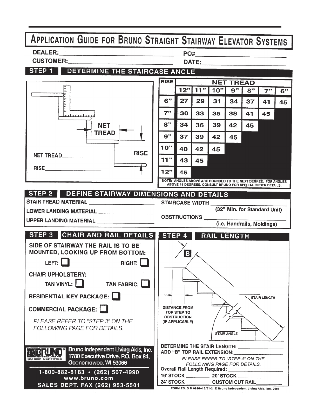
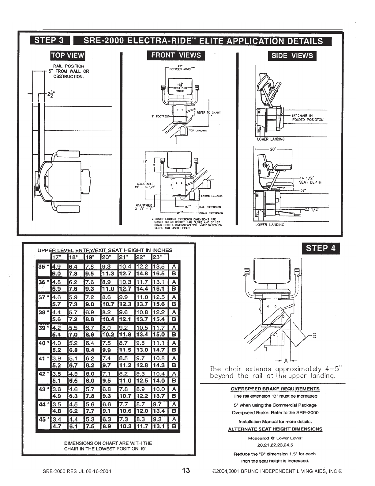
Determine the correct length for the rail. Use Steps 2 and 4 from the APPLICATION
GUIDE sent with the rail.
Cut the BOTTOM end of the rail using a chop saw or other power metal-cutting saw.
Drill (2) holes for mounting bumper assembly (see photo in Installation section).
Mount the lower bumper assembly and lower end plate.
Loosely assemble the clamp halves.
Place the clamp assemblies on the stairs in the locations specified in the installation
instructions.
NOTE: There is no clamp on the top step/landing. Consult the charts shown
in the Application Guide for proper dimensions of the B top rail extension.
Place the lower rail section in the clamps and tighten clamps enough to hold the
section immobile. Do not fully tighten at this time.
Place the upper rail section in the clamps. Make sure the upper and lower sections
mount flush.
Tighten the clamps enough to hold the section immobile. Do not fully tighten at this
time.
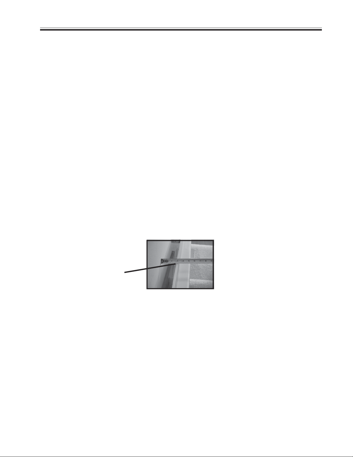
Check the rail-to-step nose clearance: MUST BE AT LEAST 1-1/4 IN.
SRE-2000 RES UL 08-16-2004
©2004,2001 BRUNO INDEPENDENT LIVING AIDS, INC.®9
Page 10

OVERVIEW (CONT.)
Secure the clamps to the stairs.
Verify that the upper and lower rail sections are straight and level.
Rail sections MUST
be vertical, or must
lean slightly toward
the back.
Rail must NEVER
LEAN FORWARD.
Feed the charge harness into the channel on the back of the rail
section.
Mount the carriage assembly.
Adjust the carriage angle by loosening the (2) adjustment bolts.
Secure the footrest to the carriage.
Install the seat assembly between the footrest mounting plate and
the seat lever.
Install the upper bumper assembly.
Route wire to household outlet.
Test unit for proper and safe operation.
Train customer in safe operation of the Stairway Elevator.
REMEMBER:
No installation is comlete until the customer has been instructed in the safe use of the
Electra-RideTM Elite Stairway Elevator. After demonstrating correct operation, have the
customer operate the elevator several times while you are available to answer questions. BE SURE THE CUSTOMER UNDERSTANDS ALL SAFETY ASPECTS OF
USING THE ELEVATOR. Patience and thoroughness in this phase of the installation
are often rewarded with repeat business and customer referrals.
©2004,2001 BRUNO INDEPENDENT LIVING AIDS, INC.® 10
SRE-2000 RES UL 08-16-2004
Page 11
INSTALLATION
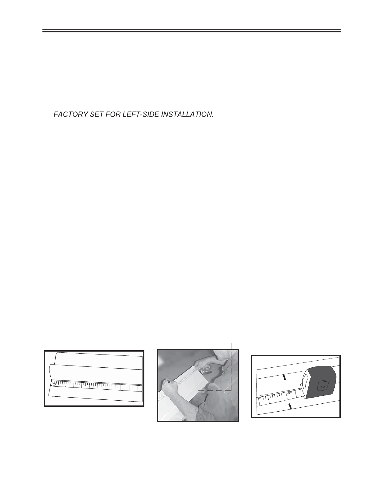
Fitting the rail
1. Determine whether the stairway elevator will be installed on the right or left side of
the stairs, as viewed from the bottom of the stairs.
NOTE: Unless otherwise specified, Bruno Stairway Elevators are shipped from the
If you wish to convert to right-side
installation, please refer to the instructions appearing later in this manual.
2. Determine the exact rail length by placing a tape measure in a straight line on
the stairs (see STEP 2 in the APPLICATION GUIDE). To this number, add
Measurement B (see STEP 4 in the APPLICATION GUIDE).
NOTE: If the unit is equipped with an overspeed brake, add 5 to the rail length.
This calculation will allow you to precisely fit the Stairway Elevator to your customer
by determining the most comfortable seat-to-floor height within the space available
at the top of the stairs.
3. Mark the length on the rail, as determined in the previous step.
NOTE: Be sure that excess length is cut off of the LOWER end of the rail.
4. After marking, and BEFORE cutting the rail, cut the cable channel back approx.
3 inches from the mark to avoid having to cut through the channel.
CUT OFF EXCESS FROM
BOTTOM END OF RAIL
SRE-2000 RES UL 08-16-2004
©2004,2001 BRUNO INDEPENDENT LIVING AIDS, INC.®11
Page 12
INSTALLATION
©2004,2001 BRUNO INDEPENDENT LIVING AIDS, INC.® 12
SRE-2000 RES UL 08-16-2004
Page 13
INSTALLATION
Page 14
INSTALLATION
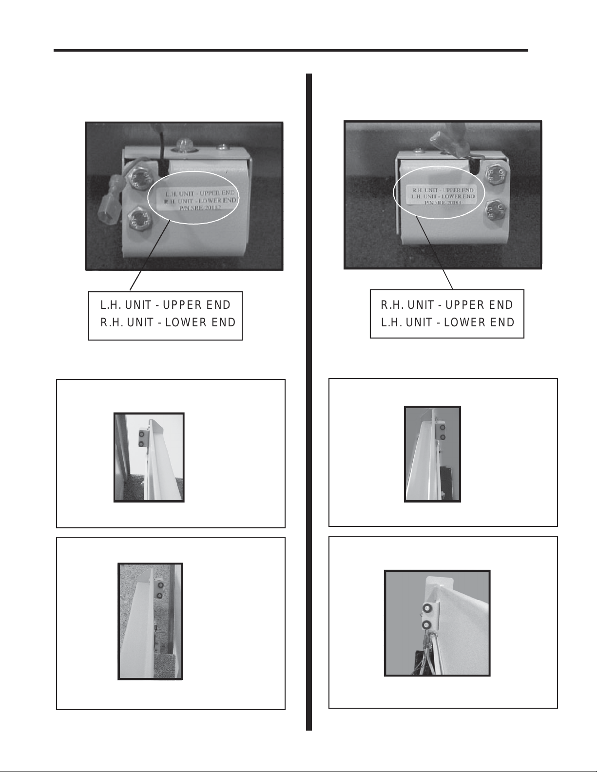
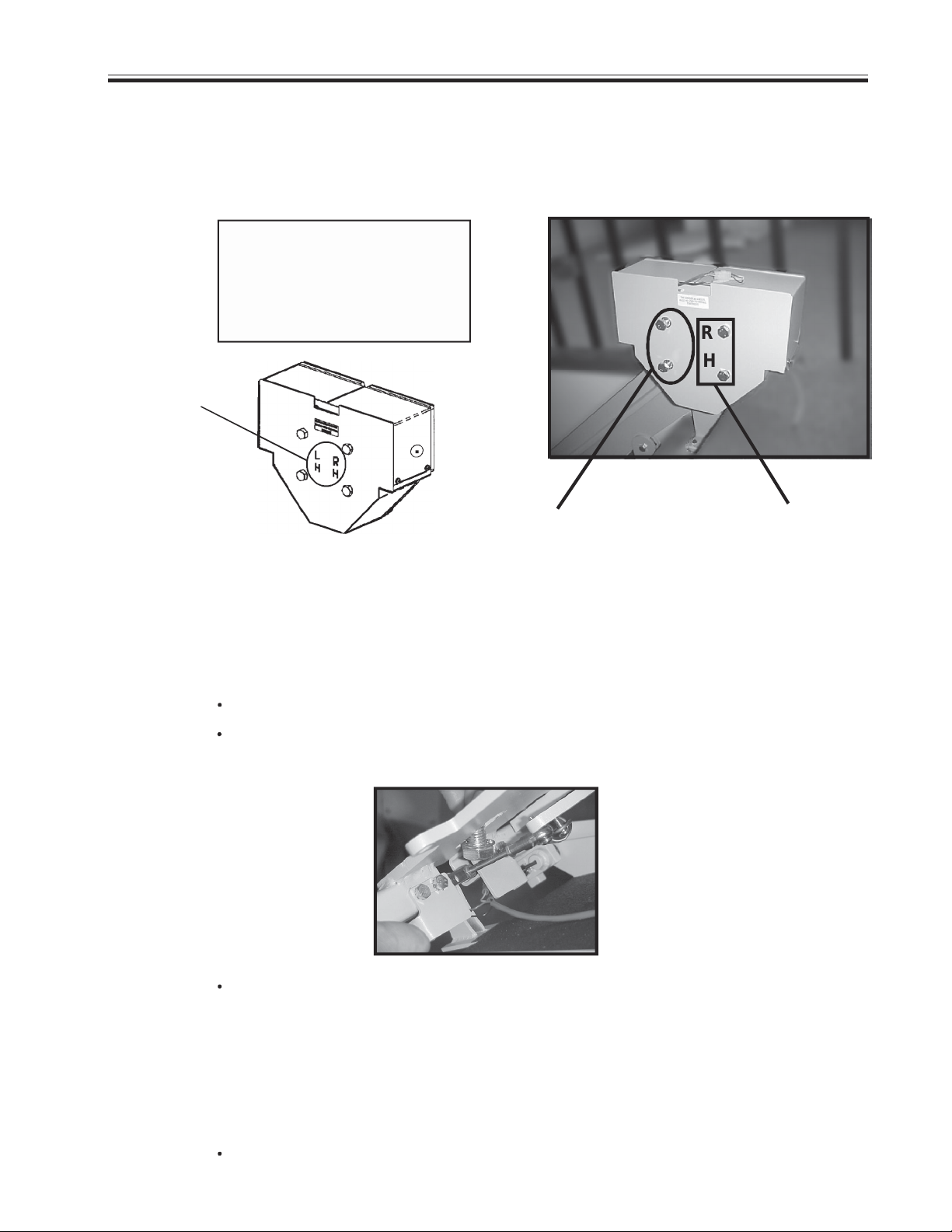
Distinguishing left- and right-hand charge bumper brackets
LEFT-HAND INSTALLATION RIGHT-HAND INSTALLATION
SRE 20001 L SRE 20001 R
SRE-20286
L.H. UNIT - UPPER END R.H. UNIT - UPPER END
R.H. UNIT - LOWER END L.H. UNIT - LOWER END
SRE-20287
Left-hand installations: Right-hand installations:
bracket SRE-20286 mounts on upper end
charge contacts point down the stairs charge contacts point down the stairs
bracket SRE-20287 mounts on lower end
bracket SRE-20287 mounts on upper end
bracket SRE-20286 mounts on lower end
charge contacts point up the stairs charge contacts point up the stairs
©2004,2001 BRUNO INDEPENDENT LIVING AIDS, INC.® 14
SRE-2000 RES UL 08-16-2004
Page 15
INSTALLATION
Cutting the rail and installing the lower bumper
IMPORTANT NOTE!
Under no circumstances should a rail section be cut shorter than
18 in. (46 cm).
There must be at least (2) clamps on a short rail section (1 at the rail
joint and 1 at the rail end). Cutting a rail shorter than 18 in. (46 cm)
would not allow enough room for the (2) necessary clamps.
Example:
After measuring the staircase, you determine you need 9 feet of rail.
With your (2) 8-foot sections you decide to use (1) 8-foot section and
cut the remaining (1) foot from the second 8-foot section. Doing this
could yield a rail piece with insufficient weld.
Instead, Bruno recommends cutting at least one foot off one of the 8-
foot sections (leaving 7 feet of rail) and then cutting 2 feet from the
second 8-foot section. You will have a (1) 7-foot section and (1) 2-foot
section, both of which are long enough to be properly mounted (2
clamps minimum per short rail).
NEVER CUT OFF THE JOINT END!
The M6 bolts securing the gear rack must remain intact.
Cut off the end with the pre-drilled charge contact mounting holes.
Then, using the provided template, redrill (2) holes on each end of the rail.
SRE-2000 RES UL 08-16-2004
©2004,2001 BRUNO INDEPENDENT LIVING AIDS, INC.®15
Page 16
INSTALLATION
Cutting the rail and installing the lower bumper (cont.)
1. BE SURE TO WEAR PROTECTIVE GLOVES AND EYEWEAR. During the
cutting process, sparks will fly and the metal rail will become very hot.
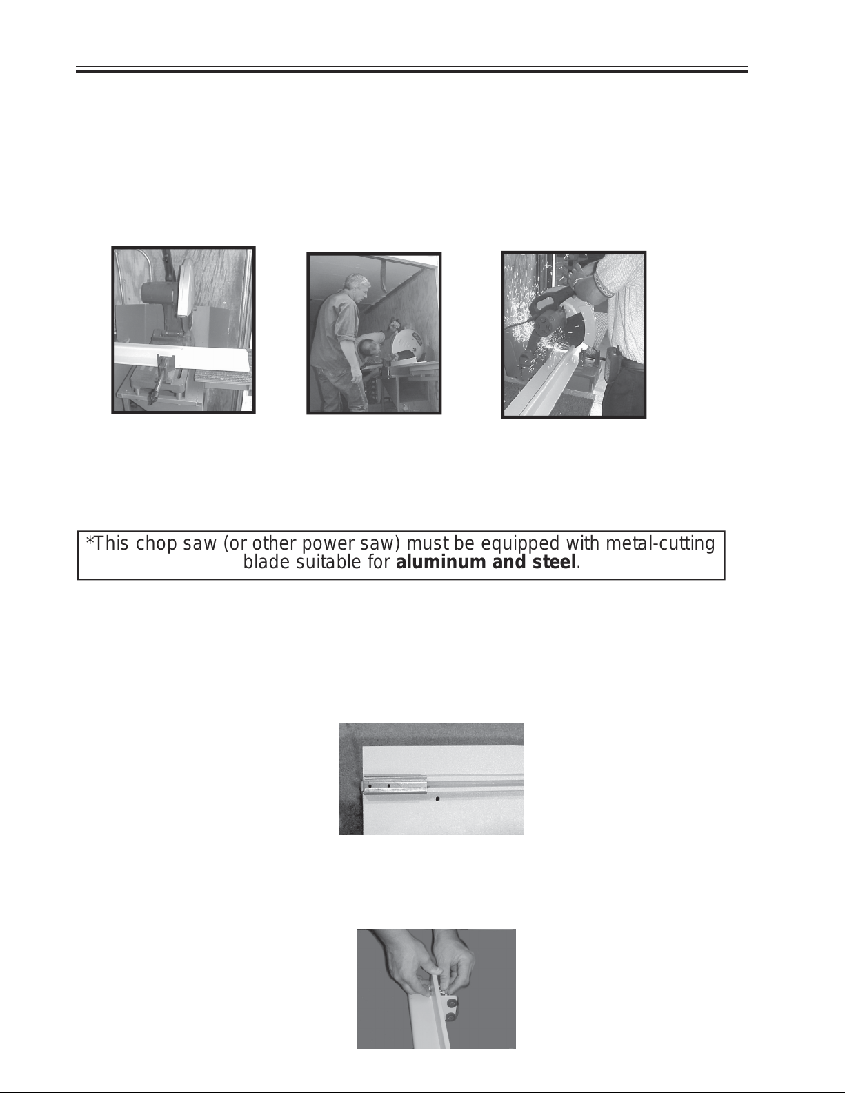
2. Place flat side of the rail on the saw bed. Carefully align the saw to the line marking
the desired finished length of the rail.
flat side of rail to saw bed align saw with mark up and down motion
3. For a precise and efficient cut, Bruno recommends the use of a chop saw*. A
down-up motion during the cutting process helps avoid overheating the saw
motor.
*This chop saw (or other power saw) must be equipped with metal-cutting
blade suitable for aluminum and steel.
4. Once the rail is cut, deburr the cut end using a file or other appropriate tool. Soften any sharp
edges which might abrade the insulation of the wiring routed to the bumper at the rail end.
5. Place the metal template (provided - see Box B of Carton 2) on rail as shown. Hold in place.
Using a 1/8 in. bit, drill two pilot holes. Switch to a 5/16 in. bit and re-drill the (2) holes.
(normally black,
template has
been lightened for
illustration purposes)
template on rail
6. Install the lower bumper assembly and end cap using the hardware provided. You
may wish to place a piece of cardboard or a non-skid rug under the end of the bottom
rail to protect the floor and to keep the rail section from sliding off the stairs.
©2004,2001 BRUNO INDEPENDENT LIVING AIDS, INC.® 16
SRE-2000 RES UL 08-16-2004
Page 17
INSTALLATION
Placing the rail clamps and rail sections
1. Place rail clamps on the stairs in the following pattern
(LONGER-footed clamp to the outside).
bottom landing
first tread up from bottom landing
two at the bottom
two in the middle (one on
each side of rail joint)
two at the top*
top landing
first tread down from top landing*
(NO CLAMP ON TOP STEP/LANDING FOR UNIT WITH
STANDARD EXTENSION)
closest tread above and below rail joint(s), then
minimum of every third tread over the remainder of
the staircase.
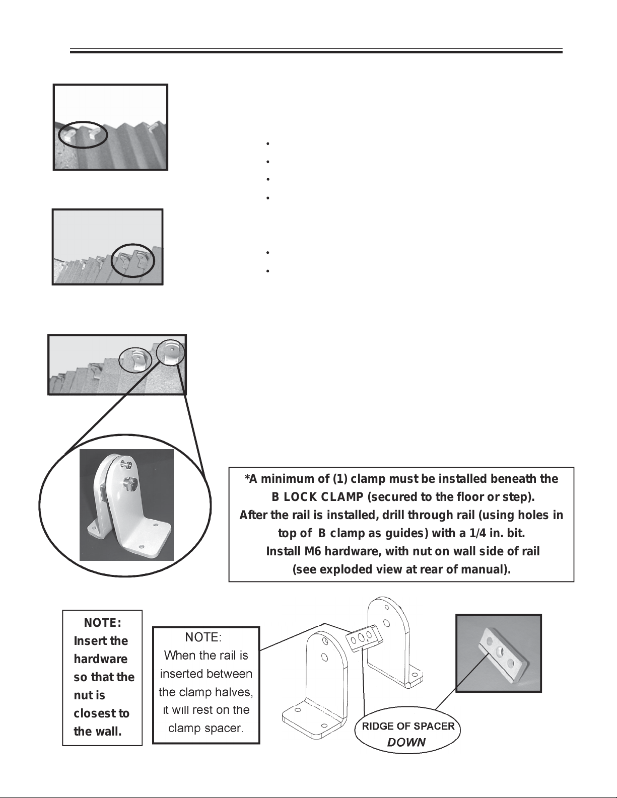
2. Mount the bottom rail section in between the clamp
halves. Tighten the hardware enough to render the
rail immobile. Do not fully tighten at this time.
3. Once the bottom rail section is mounted in the clamp
assemblies, rest the bottom of the rail against the step
noses at a distance from the wall of approx. 6 in.
B LOCK CLAMP.
NOTE:
Insert the
hardware
so that the
nut is
closest to
the wall.
*A minimum of (1) clamp must be installed beneath the
B LOCK CLAMP (secured to the floor or step).
After the rail is installed, drill through rail (using holes in
top of B clamp as guides) with a 1/4 in. bit.
Install M6 hardware, with nut on wall side of rail
(see exploded view at rear of manual).
SRE-2000 RES UL 08-16-2004
©2004,2001 BRUNO INDEPENDENT LIVING AIDS, INC.®17
Page 18
INSTALLATION
4. Place the upper section of the rail in the clamps placed in Step 1. When the rail is
inserted between the clamp halves, it will rest on the clamp spacer (see illustration,
previous page).
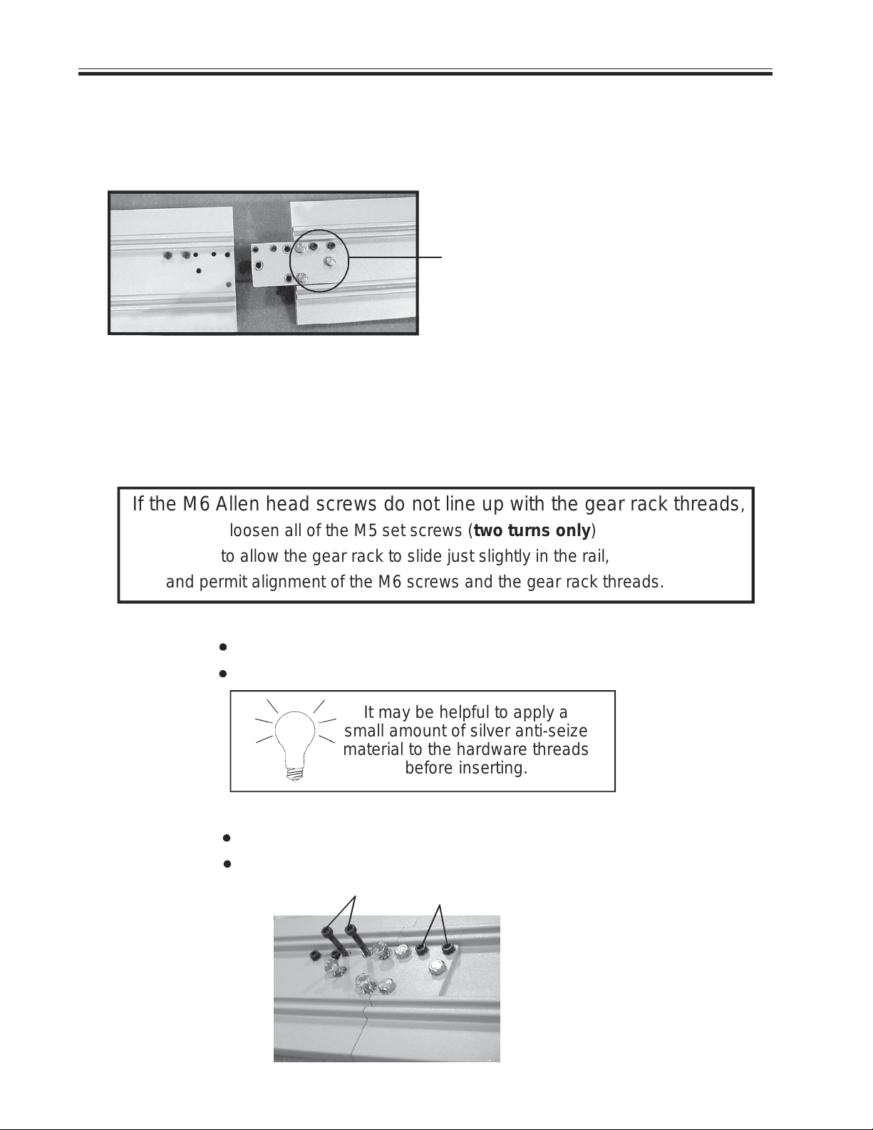
5. Slightly loosen the (3) M8 hex
head screws and the (2) M6
Allen head screws securing
the joint plate to the rail.
slightly
loosen
x 5
This makes it easier to align
the screws and the holes on
the mating rail section.
6. Gently slide the upper rail section up or down the stairs until it mates with the lower
section so that the mating ends fit flush.
7. From the kit provided, insert the (2) M6x1x45 mm Allen head and the (3) M8x1.25x16 mm
hex head screws into the appropriate holes in the joint plate. DO NOT TIGHTEN.
If the M6 Allen head screws do not line up with the gear rack threads,
loosen all of the M5 set screws (two turns only)
to allow the gear rack to slide just slightly in the rail,
and permit alignment of the M6 screws and the gear rack threads.
8. Before tightening the hardware:
check that the screw and rail/gear rack threads are properly engaged;
make sure the rail sections are flush.
It may be helpful to apply a
small amount of silver anti-seize
material to the hardware threads
before inserting.
9. Order of tightening hardware is important!
FIRST tighten the (4) M6 Allen head screws engaging the gear rack.
Then tighten the (6) M6 hex head screws.
Tighten us first!
©2004,2001 BRUNO INDEPENDENT LIVING AIDS, INC.® 18
SRE-2000 RES UL 08-16-2004
Page 19
INSTALLATION
10. Slide the top and bottom clamps up or down on the rail until they are firmly seated
on the step.
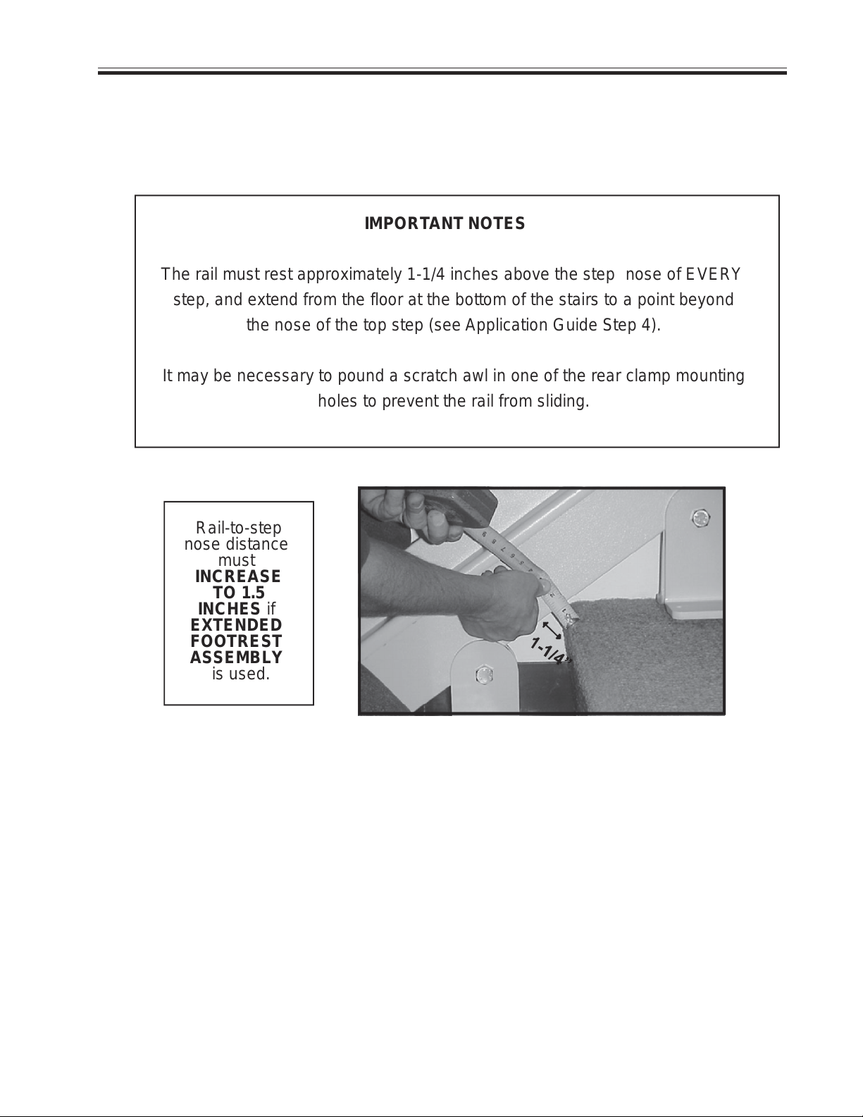
IMPORTANT NOTES
The rail must rest approximately 1-1/4 inches above the step nose of EVERY
step, and extend from the floor at the bottom of the stairs to a point beyond
the nose of the top step (see Application Guide Step 4).
It may be necessary to pound a scratch awl in one of the rear clamp mounting
holes to prevent the rail from sliding.
Rail-to-step
nose distance
must
INCREASE
TO 1.5
INCHES if
EXTENDED
FOOTREST
ASSEMBLY
is used.
STEP NOSE TO BOTTOM OF RAIL = 1-1/4 IN.
Stair profiles do vary, so it is critical to ensure
proper clearance between the step nose and the
bottom of the rail.
Failure to install the rail at the specified 1-1/4 in.
distance from the step nose will cause the footrest
to contact to steps, thus provoking intermittent
operation of the stairway elevator. If necessary,
gently slide rail and clamps toward or away from the
stair riser to adjust the clearance to the 1-1/4 in.
recommanded distance.
SRE-2000 RES UL 08-16-2004
©2004,2001 BRUNO INDEPENDENT LIVING AIDS, INC.®19
Page 20
INSTALLATION
As you tighten the
clamps around the rail
sections, regularly check
that the rail is vertical
or leaning backwards.
Rail section MUST be
at a 90-degree angle
to the stairs, OR
leaning BACK slightly.
The rail section must
NEVER lean forward.
11. Tighten the clamp hardware enough
to render the upper rail immobile.
Do not fully tighten at this time.
12. Once the rail sections are installed,
tighten the clamps. BEFORE mounting
the carriage, check the straightness of
the rail over all of the stairs by using a
level, or a plomb line along the rail. If
the rail bows or leans forward, insert
shims or readjust the clamps.
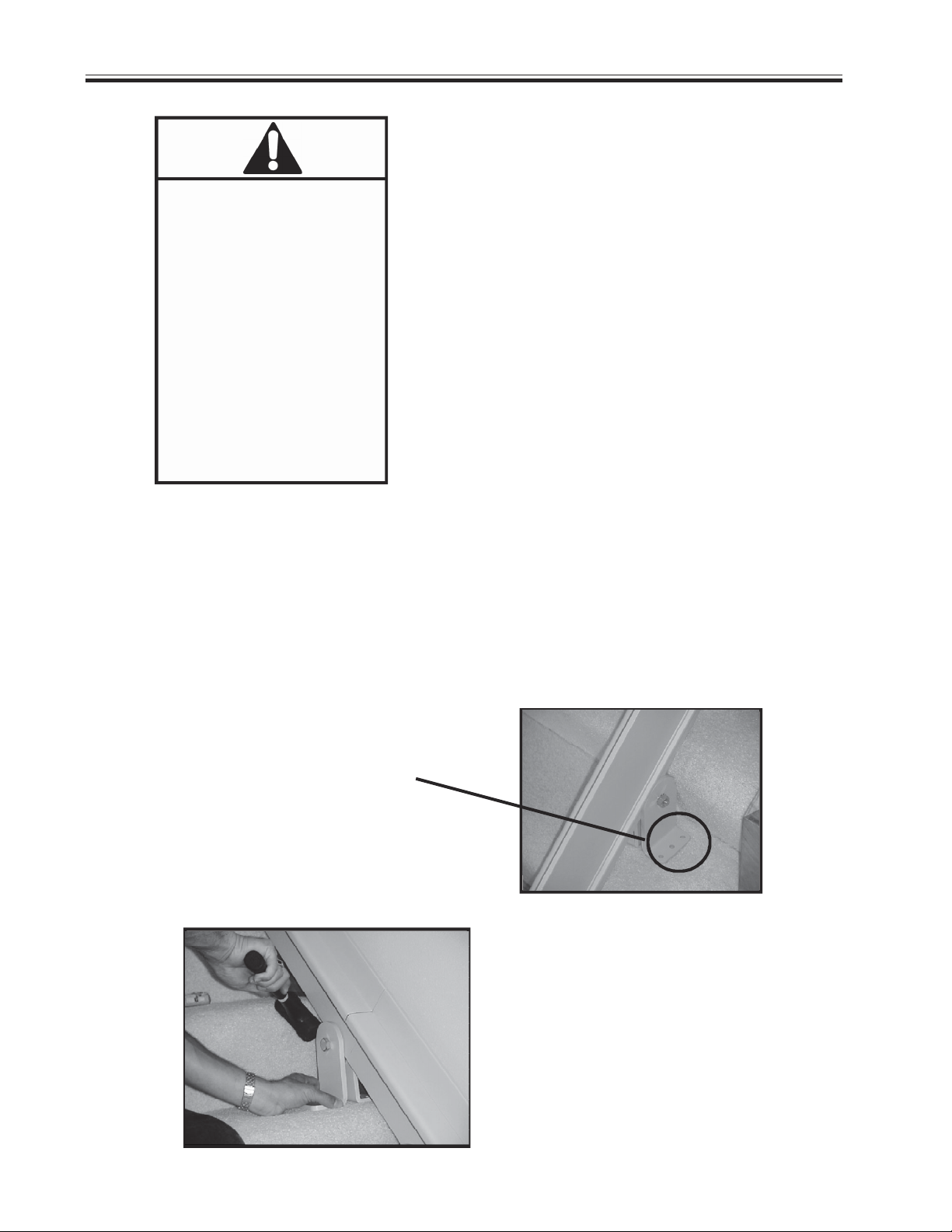
13. Secure 2 or 3 of the rail clamps to the stairs. Secure the back half of the clamps
first. The rail should be located 2-5/8 in. from the closest obstruction and the back of
the rail.
BACK FOOT OF CLAMP
(3 HOLES)
NOTE FOR
INSTALLATION ON CARPET
Before securing the rail clamps with
hardware, seat them using a deadblow
hammer. Use a rubber mallet to
compress the rug and pad before
©2004,2001 BRUNO INDEPENDENT LIVING AIDS, INC.® 20
anchoring the clamp to the step.
SRE-2000 RES UL 08-16-2004
Page 21
INSTALLATION
Bruno ships the Stairway Elevator with fasteners appropriate for WOODEN STAIR
TREADS ONLY. Installation of the Stairway Elevator on surfaces made of materials
other than wood may require different fasteners specific to the material. If you are
unsure as to which fastener applies to the installation, please contact Bruno at 1-800882-8768.
IMPORTANT MEASUREMENT:
TAKE BEFORE AND AFTER SECURING EACH CLAMP:
DISTANCE
BETWEEN BACK OF RAIL
AND
THE CLOSEST OBSTRUCTION
(for example, WALL, RAILING,LIP OF
BANNISTER, WINDOWSILL, HANDRAIL)
MUST BE AT LEAST 2-5/8 IN.
2-5/8 IN. FROM
CLOSEST OBSTRUCTION
14. For installation on hardwood stairs, Bruno recommends drilling a pilot hole for the
clamp fastener before inserting the fastener.
15. Do not secure the remaining clamps until the carriage is on the rail, and all
clearances are verified.
SRE-2000 RES UL 08-16-2004
©2004,2001 BRUNO INDEPENDENT LIVING AIDS, INC.®21
Page 22
INSTALLATION
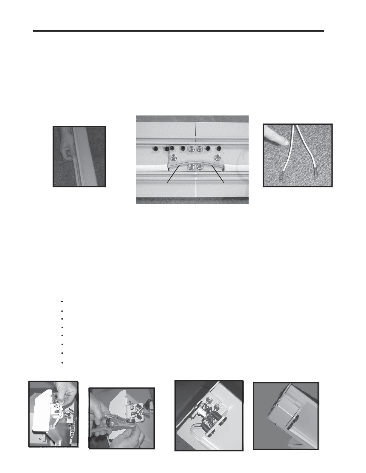
Routing the cable
Once the clamps are in place, and secure, and after verifying that the rail bottom is at least 1-1/4
in. from the bottom of the rail, and that the rail is straight, insert the power cable into the channel
that runs along the back of the rail (side closest to the wall). Determine the location of the wall
outlet. Start inserting the cable (i.e., pigtail of the charge harness) at the end (top or bottom)
closest to that outlet. Be sure to position the battery charger at this end. When routing the cable
around the joint plate, make sure that the cable rests snugly flat against the rail.
cable flat against rail
routing the cable
rib to
smooth to
red (+)
female
Notice that the end of the cable opposite the pigtail harness has been split slightly, and includes
one male and one female connector.The sheathing of one lead is ribbed (finger is pointing to
ribbed sheathing). The other leads sheathing is smooth.
The ribbed lead attaches, via FEMALE connector, to the RED positive charge lead. The smooth
lead attaches, via the MALE connector, to the BLACK negative charge lead.
Increase the split
Cut off approximately the length shown below.
Discard the old connectors.
Strip the freshly cut wire ends.
Install the new connectors provided in the kit.
Connect the two wires to the charger bracket.
Gently tuck the wires in the bumper assembly.
Attach the bumper cover.
cut to length
strip wire ends
tuck wires into
bumper assembly
attach bumper cover
black (-)
male
©2004,2001 BRUNO INDEPENDENT LIVING AIDS, INC.® 22
SRE-2000 RES UL 08-16-2004
Page 23
INSTALLATION
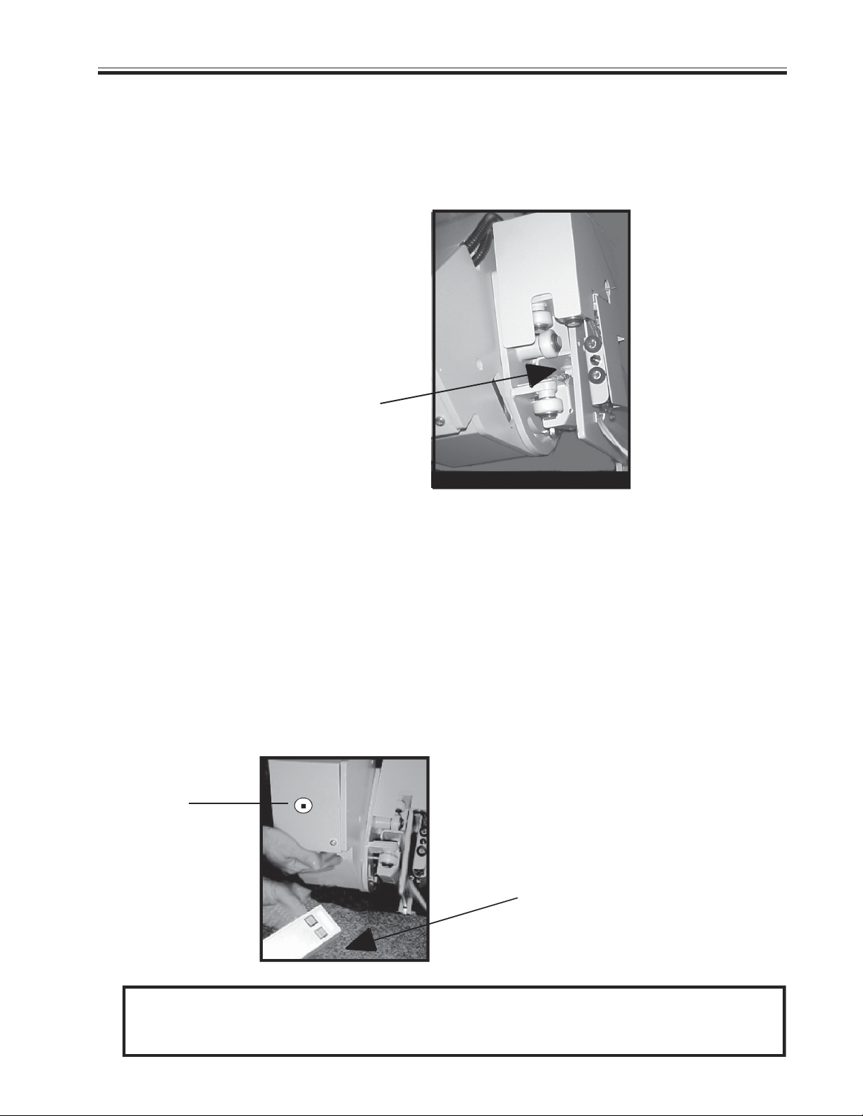
Mounting the carriage, upper bumper and upper end cap
Lift and tilt the carriage as you guide the carriage wheels onto the rail. The newlydesigned rail features a recessed gear rack to facilitate feeding the carriage onto the rail.
RECESSED GEAR
RACK FOR EASIER
MOUNTING OF CARRIAGE
ONTO RAIL
Turn on the circuit breaker. Once you feel the carriage begin to engage the gear rack,
USE THE REMOTE to finish feeding the carriage onto the rail.
Make sure the remote is pointed at the sensor.
The remote will feed the carriage smoothly onto the rail , and at the proper speed to
ensure that the gear rack and carriage mesh correctly.
sensor
USE THE REMOTE TO FULLY
ENGAGE THE CARRIAGE ON
THE GEAR RACK
****MOUNT THE UPPER BUMPER ASSEMBLY AND THE UPPER END CAP.****
SRE-2000 RES UL 08-16-2004
©2004,2001 BRUNO INDEPENDENT LIVING AIDS, INC.®23
Page 24
INSTALLATION
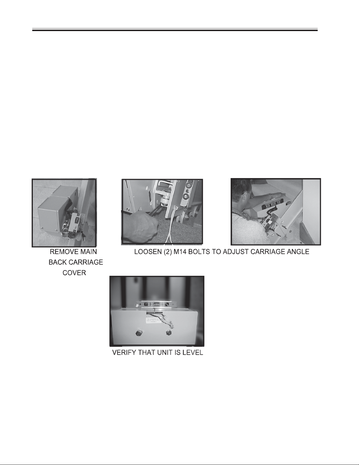
Using the remote, verify that the carriage travels smoothly down and back up the rail.
When the carriage is at the top of the stairs, check that it is level using a builders or
protractor level. To adjust the carriage angle to make the unit level, loosen the two (2)
M14 bolts on the carriage subassembly with a 22mm open-ended wrench. To access
the second bolt, remove the back main carriage cover. Gently apply downward pressure
on the right or left side of the carriage, as needed to return the carriage to a level condition. RETIGHTEN THE 2 BOLTS. Recheck with the level.
Adjusting the carriage angle
Checking the wall clearance
Now that the carriage is securely mounted on the rail, check the clearance between the
antenna and the closest obstruction (wall, handrail, windowsill, base of railing).
©2004,2001 BRUNO INDEPENDENT LIVING AIDS, INC.® 24
SRE-2000 RES UL 08-16-2004
Page 25
INSTALLATION
Note on carriage plate:
Longer M14 bolts
must be used
to install footrest
LH and RH
are burned
into the carriage
plate to indicate
correct location
of longer bolts for
footrest installation
INSTALLATION
Mounting the footrest assembly
L R
H H
longer bolts here for
left-hand installation
Longer M14 bolts must be used to install the footrest. The extra length is needed to
accommodate the plate thickness. For left-hand installations, the longer bolts are in the
holes closest to the LH. For right-hand installations, the longer bolts are in the holes
closest to the RH.
Unscrew the two (2) longer M14 x 25 mm bolts illustrated above.
Insert the bottom M14 bolt in the footrest support plate. For ease of bolt insertion in
the footrest slot, tip the footrest assembly in its folded position (see photo).
longer bolts here for
right-hand installation
Insert the top M14 bolt in the footrest support plate.
NOTE: There are (2) holes above the slotted opening. Inserting the M14 bolt in the
Tighten the two (2) bolts.
SRE-2000 RES UL 08-16-2004
UPPER hole positions the footrest about 3-1/2 above the floor. Inserting the
bolt in the LOWER hole positions the footrest about 5 above the floor.
©2004,2001 BRUNO INDEPENDENT LIVING AIDS, INC.®25
Page 26
INSTALLATION
upper
lower
Mounting the seat assembly
upper
lower
seat post assembly
outlined in black for
illustration purposes
1. Slide the seat post assembly between the footrest assembly
mounting plate and the footrest lever.
2. Secure the seat post assembly:
UPPER HOLES: Secure with two (2) M10 x 1.50 x 20mm lg hex
head cap screws, (2) flat washers and (2) lockwashers.
LOWER HOLES: Install the front cover mount with two
(2) M10 x 1.50 x 20 mm lg head head cap screws and
(2) lockwashers (no flat washers).
3. Route the wire harness of the carriage contact assembly through
the front cover mount as shown.
4. Connect the two ends of the wire harness.
connect wiring harness
FRONT
COVER
MOUNT
©2004,2001 BRUNO INDEPENDENT LIVING AIDS, INC.® 26
SRE-2000 RES UL 08-16-2004
Page 27
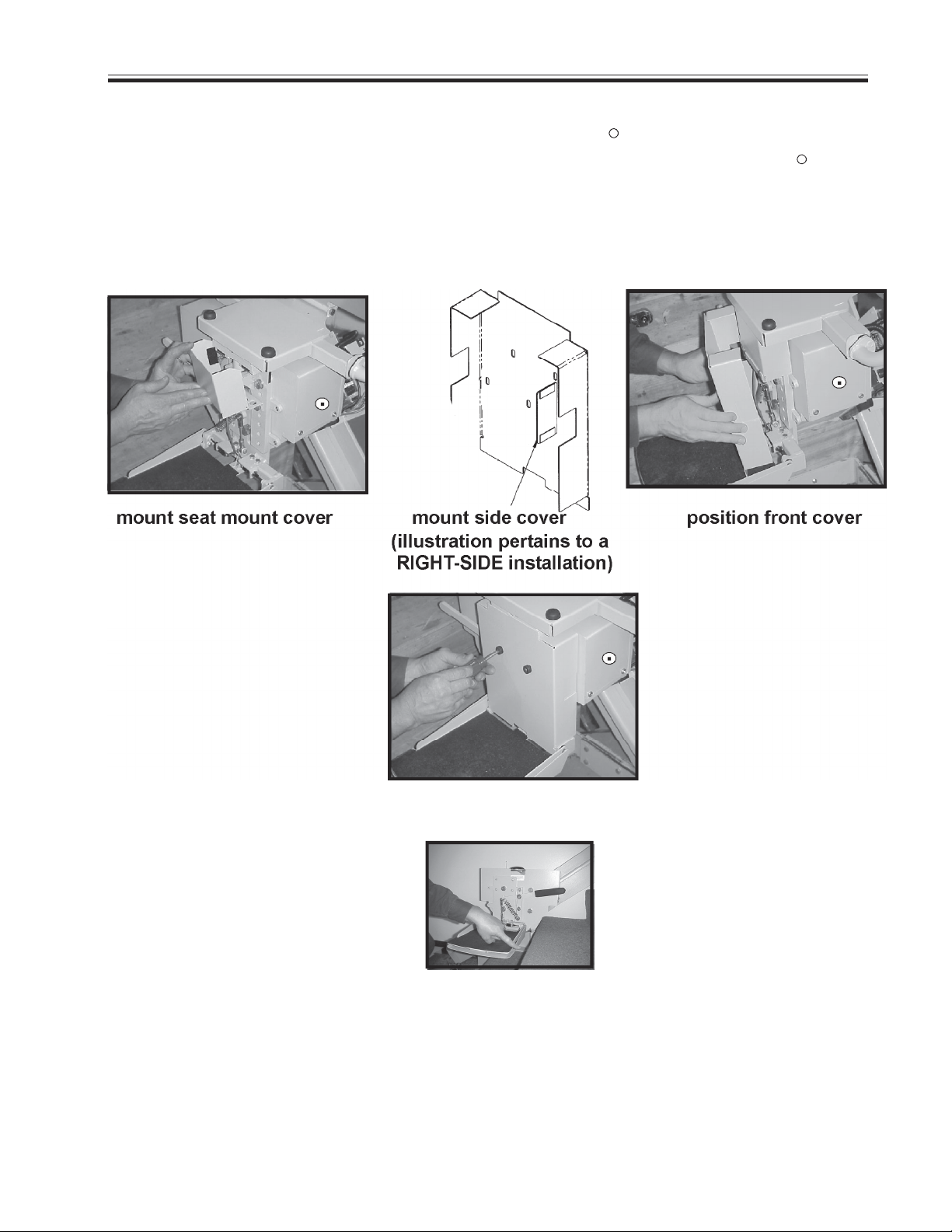
INSTALLATION
5. Mount the seat mount cover using the pre-attached Velcro strips.
6. Mount the side cover to cover the unused opening, using the pre-attached Velcro strips
R
R
(cover the hole on the right for left-side installations, and the hole on the left for right-side
installations).
7. Position the front cover as shown below and secure with the black bumpers and
#8 x .75 in. lg Phillips head sheet metal screws.
secure front cover
8. RUN THE CARRIAGE UP AND DOWN THE RAIL TO VERIFY ALL CLEARANCES.
9. Finish mounting and securing all rail clamps.
SEAT HEIGHT ADJUSTMENT
Remove all (4) M10 x 20mm bolts. Slide the seat up or down. Line up the holes on the
seat post with the holes on the footrest mounting plate at the desired height. Reinsert the
M10 x 20 mm bolts and corresponding washers. Tighten.
SRE-2000 RES UL 08-16-2004
©2004,2001 BRUNO INDEPENDENT LIVING AIDS, INC.®27
Page 28
INSTALLATION
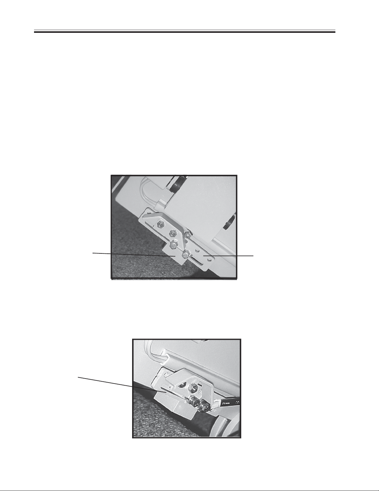
Mounting the final limit ramp kit
The final limit ramp kit is a safety feature which enhances the stopping capability of the
Electra-RideTM Elite. It mounts on the top rail section, on the side facing away from the
stairs.
Before installing the final limit ramp kit, run the carriage down a foot or two to provide
greater access to the mounting hardware.
Mount the final limit ramp kit on the bottom side of the rail as shown below.
FINAL LIMIT
ADJUSTMENT
FINAL LIMIT
ADJUSTMENT BAR
BLOCK
Using the holes for the ramp and/or the slotted adjustment bar and block allows for fine
adjustment of the position of the final limit ramp kit in relation to the clamp on the top
step.
ADJUSTMENT
SLOT
To attach the block to the rail, tighten the (2) M6x1x30mm bolts ONLY.
To secure the adjustment bar, tighten the (2) M6 nuts on the M6x1x30mm bolts.
©2004,2001 BRUNO INDEPENDENT LIVING AIDS, INC.® 28
SRE-2000 RES UL 08-16-2004
Page 29

INSTALLATION
INFRARED CALL/SEND TRANSMITTER
The call/send system on the Bruno SRE-2000 is based on infrared (IR) controls,
the same type of control used for televisions and stereos.
Like a television remote, the SRE-2000 hand-held transmitter may experience
certain types of interference. Receivers are mounted on both sides of the SRE-2000
carriage to minimize interference.
Should interference occur, the unit will stop. This feature has been integrated
into the SRE-2000 to ensure your safety.
The direct line between the transmitter to either of the (2) transmitters should
be clear of obstacles for optimal operation. It may be necessary to reposition the transmitters
so that they are aimed at the carriage.
To reduce the possibility of interference:
While riding in the seat, ALWAYS operate the Elevator using the rocker switch
on the armrest.
Operating the SRE-2000 with a transmitter while riding in the seat
can lead to signal interference.
DO NOT mount the transmitters behind an obstacle such as a rail post.
DO NOT allow direct sunlight to shine on the receivers (blinding the receivers
on the carriage).
DO replace transmitter batteries regularly.
Depleted or nearly-depleted batteries alter the effective range of the transmitter.
DO keep the transmitter and receiver lens free of dirt and debris.
Use a non-abrasive cleaner suitable for glass or acrylic surfaces.
Do not use polishes or cleaning products containing wax. These products
will leave a film on the lens that will reduce the signal transmission range.
SRE-2000 RES UL 08-16-2004
©2004,2001 BRUNO INDEPENDENT LIVING AIDS, INC.®29
Page 30

INSTALLATION
CALL/SEND TRANSMITTER
The 9V battery is inserted upside down in the IR transmitter
when shipped from the Bruno factory. Prior to operating
the SRE-2000, the installer must remove the battery and
reinsert it so that the (+) and (-) poles are properly connected.
MOUNTING THE CALL/SEND TRANSMITTERS
TO THE WALL
Remember to mount the transmitters
in locations which are out of the reach
of children, yet always visible to the
operator from the stairway elevator.
Step 4
Insert the longest screw provided in the mounting
hardware kit (see illustration above left) through the
top hole in the bracket and through the corresponding
hole in the back of the transmitter. Tighten, without
overtightening to avoid damaging the transmitter back.
NOTE:
INSTALLATION OF THE
CALL/SEND UNIT MAY VARY
BY LOCAL CODE. PLEASE
REFER TO LOCAL CODES
FOR INSTALLATION
GUIDELINES.
Step 5
©2004,2001 BRUNO INDEPENDENT LIVING AIDS, INC.® 30
SRE-2000 RES UL 08-16-2004
Page 31

INSTALLATION
Testing the Call/Send Transmitters
A slight delay will occur between the time the rocker switch is depressed and the initiation
of carriage movement. This is normal and is a function of the soft start feature of the
controller.
Run the unit up and down the stairs using the rocker switch on the carriage. The
unit should operate in such a way that the arrow depressed on the rocker switch
corresponds to the desired direction of travel.
The unit should travel noticeably faster going up than down.
Run the unit up and down the stairs using the remote call/send transmitters. Test
both transmitters.
Push the seat into the stored position and run the unit up and down the stairs with the
remote call/send transmitter.
With the seat in the central riding position, move the Elevator completely down and up
the rail, while observing the elevator-to-wall clearance. A clearance of 1/2" to 1" is
acceptable. Repeat the run with the seat in the folded position. If necessary, adjust
the rail placement by sliding it closer to, or further from the wall.
Verify proper operation of the following: speed, direction, final limit switch, footrest
safety switch, seat swivel safety switch, and remote call/send transmitter.
TRAIN THE CUSTOMER TO USE THE STAIRWAY
ELEVATOR CORRECTLY AND SAFELY. BE SURE TO
HAVE THE CUSTOMER OPERATE THE UNIT WHILE
YOU ARE THERE TO ANSWER ANY QUESTIONS OR
CONCERNS. REMIND THE CUSTOMER TO ALWAYS USE
THE SEAT BELT.
SRE-2000 RES UL 08-16-2004
©2004,2001 BRUNO INDEPENDENT LIVING AIDS, INC.®31
Page 32

INSTALLATION
LEARNING THE REMOTE INFRARED TRANSMITTER
(not necessary when installing unit for the first time)R
The operating channel of the two (2) infrared transmitters
included with the SRE-2000 is pre-set at the Bruno factory.
Should it become necessary to re-learn the transmitters
(for example, if there are multiple units in the same location,
or in the event you have to replace transmitters) proceed as follows:
1) Turn off the circuit breaker.
2) Remove the carriage cover to expose the circuit board.
3) Locate the LEARN switch on the circuit board (see illustration to left).
(c)
(a)
(c)
(b)
4) On one of the IR TRANSMITTERS, remove the screw (a) securing
the back to the transmitter. [If the transmitter is mounted to a
wall, unscrew the (2) mounting bracket screws, turn the
transmitter over and remove screw (a) securing the mounting
bracket and the transmitter back.]
5) Remove the transmitter back and set aside with its screw.
6) On the TRANSMITTER circuit board, locate the switch (b)
labelled "SW".
7) Change the configuration for switches 1 and 2.
Note: There are four possible configurations:
1 up, 2 down (default manufacturer's setting)
1 up, 2 up
1 down, 2 up
1 down, 2 down
8) Once you have changed the switch positions:
Turn on the CARRIAGE circuit breaker.
Wait until you hear a BEEP.
Press and hold the LEARN switch on the CARRIAGE circuit
board.
The red LED on the carriage circuit board will glow.
AS YOU HOLD DOWN the LEARN switch, press one of
the TRANSMITTER pushbuttons.
When the red LED on the carriage circuit board goes out,
release the LEARN switch and the transmitter pushbutton.
©2004,2001 BRUNO INDEPENDENT LIVING AIDS, INC.® 32
SRE-2000 RES UL 08-16-2004
Page 33

Learning the Call/Send Transmitters
NOTE:
While using the remote
call/send, you may
experience some
intermittent operation.
This will not harm the
unit. However, while
using the rocker switch,
operation should NOT be
intermittent.
INSTALLATION
Depress the DOWN transmitter button (if the carriage
is at the top of the rail), or the UP transmitter button (if
the carriage is at the bottom of the rail).
If the carriage moves, the new configuration has been
accepted and the transmitter relearned.
9) Make sure both transmitters are set to the same switch
configuration.
10) Reassemble and secure the transmitter back (remount on
wall if applicable).
11) Reassemble and secure the carriage cover.
Transmitter Battery
The 9V battery is inserted upside down in the IR
transmitter when shipped from the Bruno factory.
Prior to operating the SRE-2000, the installer must
remove the battery and reinsert it so that the (+) and
(-) poles are properly connected.
To access the transmitter battery, open the door on
the back of the transmitter as shown to the left.
WHEN THE INSTALLATION IS COMPLETE
Verify proper operation of the power supply, call/send transmitters, on/off switch,
footrest, safety switches, and carriage limit switches.
Inform the customer of the location of the Owner's Manual. Encourage
him/her to become familiar with its contents.
Train the customer to use the stairway elevator correctly and safely. Be sure to
have him/her operate the unit while you are there to answer any questions and
address any concerns.
SRE-2000 RES UL 08-16-2004
©2004,2001 BRUNO INDEPENDENT LIVING AIDS, INC.®33
Page 34

INSTALLATION
Lubrication
Run elevator up and down the rail several times.
Apply a thin layer of white lithium grease on the gear rack ONLY.
Regular cleaning will keep the rail free of dust and dirt.
Apply thin layer
of white lithium
grease to
gear rack only.
©2004,2001 BRUNO INDEPENDENT LIVING AIDS, INC.® 34
SRE-2000 RES UL 08-16-2004
Page 35

ELECTRICAL
CIRCUIT BOARD DIAGNOSTICS
The circuit board provided on the SRE-2000 is equipped with (4) diagnostic modes that
continuously monitor the units operation. This choice of operational modes allows the
SRE-2000 to respond to the requirements of a wide variety of installations.
NOTE : The SRE-2000 is shipped in the MULTI-USER/DIAGNOSTIC MODE.
MULTI-USER/DIAGNOSTIC MODE
Provides full range of Audio diagnostic notices:
* Circuit Board Power Up : Chirp
* Safety Device Activated: Chirp
* Elevator Stopped Off Charge Bumper: 5 Beeps (4 short and 1
long) Repeats every 3 minutes until the Elevator is returned to the bumper.
* Seat Safety Disengaged: Chirp repeats every 3 seconds until seat safety
switch is re-engaged.
* Battery Voltage Drop : 5 Beeps (3 short and 2 long)
Repeats every 4 minutes until seat safety switch is disengaged, the
battery voltage increases,or the switch is pressed.
* Battery Voltage Critical: 5 Beeps (2 short and 3 long)
Repeats once a minute until the voltage exceeds 16V or the switch is
pressed.
* Switch Active During Power Up: 3 Beeps / Pause
Repeats beeps every 5 seconds until all switches are off.
* More Than One Switch Active: 3 Beeps / Pause/X beeps (number of beeps
indicates which switches are active)
Repeats every 30 seconds until all switches are off.
* Transmitter ID Memory Full: 3 Beeps (1 short and 2 long)
SINGLE-USER MODE
Provides the same audio diagnostic notices as the Multi-User/Diagnostic Mode,
except for the Seat Safety Disengaged notice.
QUIET MODE
In the QUIETmode, none of the Audible Warning Messages is active.
BATTERY WARNINGS ONLY MODE
Provides battery audio diagnostic only.
* Elevator Stopped Off Charge Bumper: 5 Beeps (4 short and 1 long)
Repeatsevery 3 minutes until Elevator is returned to the bumper.
* Battery Voltage Drop : 5 Beeps (3 short and 2 long)
Repeats once every 4 minutes until the seat safety switch is disengaged or
the battery voltage increases.
* Battery Voltage Critical: 5 Beeps (2 short and 3 long)
Repeats once a minute until voltage is above 16 V.
SRE-2000 RES UL 08-16-2004
©2004,2001 BRUNO INDEPENDENT LIVING AIDS, INC.®35
Page 36

ELECTRICAL
CIRCUIT BOARD DIAGNOSTICS
CHANGING THE PCB DIAGNOSTIC MODE
* Turn the Circuit Breaker on the carriage to `OFF'.
AUDIO REFERENCE
Chirp .25 Seconds
Short Beep .5 Seconds
Long Beep 1.5 Seconds
Pause 1 Second
* Remove Left Carriage Cover.
* Unit is shipped in Multi-User Diagnostic Mode. Changes are made via the
Number 1 and Number 2 positions on the 4-Ganged DIP Switch.
4 GANGED DIP SWITCH (S1)
DIAGNOSTIC MODE DIP SW NO. 1 DIP SW NO. 2
Multi-User OFF OFF
Single-User ON OFF
Quiet OFF ON
Battery Warning Only ON ON
OTHER CIRCUIT BOARD FEATURES
Also located on the 4-ganged DIP Switch are Switch No. 3 (LH/RH installation) and Switch No.
4 (coast delay). Refer to the Conversion to Right-Hand Installation instructions for changing
Switch No. 3. The coast delay option (Switch No. 4) has been provided in cases of interference
which may cause intermittent operation. The normal setting is 600 mSec. of coast. Should the
unit lose the remote call/send signal, this can be increased to 900 mSec. by moving Switch No.
4 to the `ON' position.
©2004,2001 BRUNO INDEPENDENT LIVING AIDS, INC.® 36
SRE-2000 RES UL 08-16-2004
Page 37

ELECTRICAL
CIRCUIT BREAKER
The on/off switch is built into the circuit breaker which is provided to protect the battery, controller
and motor circuits in the Stairway Elevator carriage. It is unlikely that this circuit breaker will ever
trip in normal use. However, should the Elevator fail to operate, check the circuit breaker as a
first troubleshooting step, and reset it if necessary.
It is also recommended that you determine the reason that the breaker tripped, and correct the
situation. Two most frequent causes of a tripped circuit breaker: (1) foreign object jamming the
rail or gear rack and (2) exceeding the rated load capacity leading to circuit overload of the
Elevator.
CIRCUIT BREAKER WITH ON/OFF
SWITCH BUILT IN
When the installation is complete, test the unit for correct operation of call/send, `on/off'
switch, footrest, safety switches, carriage limit switches and seat safety switch.
Train the customer to use the stairway elevator correctly and safely. Be sure to have them
operate the unit while you are there to answer any questions or concerns.
SRE-2000 RES UL 08-16-2004
©2004,2001 BRUNO INDEPENDENT LIVING AIDS, INC.®37
Page 38

ELECTRICAL
*NOTE:
A flashing green
light on the charger
indicates a problem
with the
battery.
If the
battery has not
reached the end of
the first stage of
the operation
within 18 hours, the
charger may
determine that a
problem exists
within the battery.
BATTERY CHARGER
BATTERY CHARGER SEQUENCE IS AS FOLLOWS:
RED LED `ON' = AC Power on (power cord plugged in)
YELLOW CONTINUOUS LED = Batteries charging
FLASHING YELLOW LED = Batteries are 80% charged
GREEN CONTINUOUS LED = Batteries in charge completing
mode (or float/standby condition)
FLASHING GREEN LED = Possible battery fault detected after
battery has failed to reached the end of the first stage of charging (continuous yellow LED) after approx. 18 hours.
Consult an authorized Bruno dealer.
BATTERY CHARGER FUSE REPLACEMENT:
If the charger is subject to a power line surge, the AC input fuse
may blow. This fuse is located beneath the power cord from the
wall outlet to prevent shock hazard.
To replace the charger fuse:
1) Remove power cord from wall outlet and charger socket.
2) Pull out on the fuse access panel.
3) Remove fuse.
4) Replace with the same size and type: (BUSS # GMC 4) 5 x
20mm-4AMP/125V-TIME LAG
©2004,2001 BRUNO INDEPENDENT LIVING AIDS, INC.® 38
SRE-2000 RES UL 08-16-2004
Page 39

INSTALLATION
ELECTRICAL
Mounting the Battery Charger
Position the charger in a suitable permanent location, near the end of the rail. Make
sure that its placement will not create a tripping hazard. Connect the power cord to the
nearest wall or floor outlet.
NOTE: THE CHARGER SHOULD BE PLUGGED INTO A HOUSEHOLD OUTLET ALL OF
THE TIME. THE ELEVATOR IS DESIGNED SO THAT THE BATTERIES WILL BE CHARGED
WHEN THE CARRIAGE IS AT EITHER END OF THE RAIL. IT IS IMPERATIVE THAT THE
CARRIAGE BE "PARKED" AT THE END OF THE RAIL WHEN IT IS NOT IN USE TO MAINTAIN FULL BATTERY CHARGE.
If the charger cannot be parked at one end of the rail (for example, on stairways with a door at
the top), use the remote call/send transmitter to send the carriage to the other end. In this way,
the carriage will properly engage the charging contacts, ensuring that the batteries will remain
fully charged.
*BATTERY
CHARGER
Be sure to
place in plain
view to
monitor proper
charging.
BATTERY CHARGER
CONNECTED TO WIRING
HARNESS
(BEFORE MOUNTING
PLATE AND STRAP ARE
INSTALLED)
MOUNTING PLATE AND STRAP
NOTE:
IF CHARGER PLUG AND WIRE
ARE LOCATED IN A VULNER-
ABLE
LOCATION, A PLUG LOCK TO
PREVENT ACCIDENTAL
UNPLUGGING IS
AVAILABLE AT HARDWARE
STORES.
AMBER LED INDICATES
"CHARGING CONTACT" AND
CORRECT POLARITY.
BE SURE CHARGER IS
PLUGGED INTO A "LIVE"
OUTLET.
REMINDER: ALWAYS "PARK" THE
CARRIAGE AT THE UPPER OR LOWER
END OF THE RAIL TO KEEP
BATTERIES FULLY CHARGED
SRE-2000 RES UL 08-16-2004
©2004,2001 BRUNO INDEPENDENT LIVING AIDS, INC.®39
Page 40

CONVERSION TO RIGHT-HAND INSTALLATION
CONVERSION TO RIGHT-HAND INSTALLATION
As shipped from the factory, the Electra-RideTM Elite is set up for left-side installation (as
viewed from the bottom of the stairs).
To convert the unit for right-side installation, perform the following operations:
ELECTRICAL
1. Make sure the circuit breaker switch on the rear of the carriage is in the OFF position.
2. Remove the back carriage cover and the left side cover.
3. Set the No. 3 DIP Switch on the 4-ganged dip switch to the ON position.
NOTE: It is imperative that the circuit breaker be turned OFF while changing from
left-hand to right-hand installation. Otherwise, the board will not accept the change.
©2004,2001 BRUNO INDEPENDENT LIVING AIDS, INC.® 40
SRE-2000 RES UL 08-16-2004
Page 41

CONVERSION TO RIGHT-HAND INSTALLATION
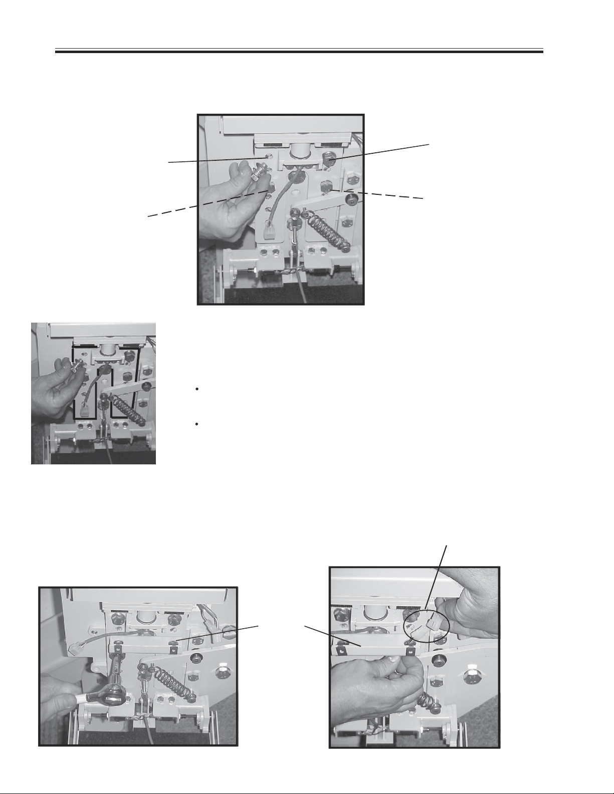
MECHANICAL
4. Loosen (but do not remove) the bottom (M14) carriage bolt.
5. Remove the top (M14) carriage bolt.
6. Apply pressure with your hands to the top of the carriage to pivot it to the opposite
side.
7. Reinsert the top (M14) carriage bolt. Tighten.
8. Tighten the bottom (M14) carriage bolt.
9. Reinstall back and side carriage covers.
NOTE: When converting from a left-hand to a right-hand
installation (as viewed from the bottom of the stairs),
the length of the (3) black, ribbed wire harnesses will increase
when you change the angle of the carriage.
Be sure to tuck these harnesses into the carriage.
DO NOT bundle them next to the circuit
board to avoid contact between the harnesses and
board components.
10. On the FRONT of the carriage, remove the longer (M14) bolts ON THE LEFT and the
shorter (M14) bolts ON THE RIGHT.
remove
longer bolts: shorter bolts:
switch to right side switch to left side
SRE-2000 RES UL 08-16-2004
remove
©2004,2001 BRUNO INDEPENDENT LIVING AIDS, INC.®41
Page 42

CONVERSION TO RIGHT-HAND INSTALLATION
11. Insert the shorter bolts ON THE LEFT, and the longer (M14) bolts ON THE
RIGHT. The bolts should now be on the side opposite the starting location.
Right-hand installation
shorter
bolts on left longer bolts
on right
12. ONLY TIGHTEN THE SHORT BOLTS
to secure the front cover. The long bolts are used to fasten the footrest.
13. On the footrest, while applying downward pressure on the handle, remove the Phillipshead screw attaching the adjusting rod to the handle.
14. Remove the spring from the handle.
15. Remove the (2) M10 bolts securing the bracket
to the footrest plate.
16. Swing the handle around so it is on the up side
of the staircase.
17. Attach the handle bracket to the footrest plate with the (2) M10 bolts.
18. Reattach the spring.
19. Apply downward pressure to the handle while
attaching the adjusting rod to the handle with
the Phillips-head screw.
20. Verify clearances, especially the footrest-to-stepnose
clearance.
©2004,2001 BRUNO INDEPENDENT LIVING AIDS, INC.® 42
SRE-2000 RES UL 08-16-2004
Page 43

CONVERSION TO RIGHT-HAND INSTALLATION
CHANGING THE ROCKER SWITCH TO THE LEFT ARM
1. Unscrew the (2) black screw bumpers.
2. Remove the seat frame cover.
3. Unplug the rocker switch harness located under the seat frame.
4. Loosen both arm cover screws to remove the covers.
5. With needle-nose pliers, remove the rocker switch harness from the switch.
6. Carefully pull the rocker harness down throught the arm tube.
7. Using masking tape, tape the three connectors IN LINE with each other,
in a staggered configuration. This will facilitate feeding the wires through the arm
tube.
8. From the bottom of the left arm tube, slide the rocker harness upward. When the
taped connectors are showing at the top of the arm tube, pull the wires out to the
end of the arm pad using needle-nose pliers.
9. Using a #5 metric Allen wrench:
remove the (2) front flat head screws on the seat frame, and
LOOSEN (but do not remove) the (2) back screws.
10. Tilt back the seat.
11. Swing the small rocker harness (under the seat frame) toward the left-arm side to
plug into the harness in the arm tube.
12. CAREFULLY tighten all (4) flat-head screws. Use CAUTION to avoid pinching any
wires.
13. Remount the seat frame cover and secure with the 2 black screw bumpers.
14. Plug the rocker harness into the rocker switch.
15. Slide the covers onto both ams. Tighten the screws.
SRE-2000 RES UL 08-16-2004
©2004,2001 BRUNO INDEPENDENT LIVING AIDS, INC.®43
Page 44

SPEED CONTROL ADJUSTMENT
SPEED CONTROL LOCATION AND ADJUSTMENT
A provision for adjusting speed is one of the unique features of the SRE-2000 Electra-Ride
SPEED CONTROL LOCATION AND ADJUSTMENT
TM
Elite. The speed adjustment potentiometer is located outside the carriage. Adjustment instructions follow:
Loosen the collet nut on the speed control potentiometer
approximately one-half turn.
The speed may be adjusted by turning the slotted shaft on the potentiometer
(clockwise = faster, counterclockwise = slower). With the customer on the unit
make several test runs to arrive at the most to appropriate speed setting.
When the speed has been properly set, retighten the collet nut.
Recheck the speed.
SPEED ADJUSTMENT POTENTIOMETER
COLLET NUT
©2004,2001 BRUNO INDEPENDENT LIVING AIDS, INC.® 44
SRE-2000 RES UL 08-16-2004
Page 45

MAINTENANCE
GENERAL INFORMATION
If the batteries become discharged, the carriage will move more slowly until the
voltage drops to a point where the controller will shut off. In this event, pause for a
moment, then run the carriage "down" until it engages the charge contacts.
(Partially charged batteries will run the carriage "down", but not "up".) Confirm that
the charger is plugged into a "live" outlet and wait for the batteries to recharge.
Your Stairway Elevator s designed to give you many years of reliable service with
minimal maintenance. To ensure the best service life, observe the following:
1. Keep the stair rail channel clean and free of debris.
2. Park the carriage at one end of the stair rail so that the batteries
charge when not in use.
3. Keep the battery charger plugged into a "live" outlet.
4. Have a qualified service technician clean, check, and
grease the unit at least once a year. Refer to the Installation Manual
for gear rack lubrication instructions.
VACATION/LONG-TERM STORAGE
If the Elevator will not be in use for an extended period of time the circuit breaker should be
turned off. After the Elevator is turned off, the charger should be unplugged from the wall
outlet.
DO NOT unplug the charger from the wall outlet without turning off the circuit breaker. This
will result in battery discharge or premature battery failure.
TURNING THE UNIT BACK ON
[ ] To turn the unit back on, turn the circuit breaker on and plug the charger back
into the wall outlet.
NOTE: The batteries may need to be recharged before normal use if the
Elevator remained in the OFF position for an extended period of time. To do so,
simply reconnect the charger to the wall outlet and make sure the circuit breaker is
in the ON position
RECYCLE BATTERIES
IN ACCORDANCE
WITH REGULATIONS
IN FORCE IN YOUR
SRE-2000 RES UL 08-16-2004
AREA.
©2004,2001 BRUNO INDEPENDENT LIVING AIDS, INC.®45
Page 46

MAINTENANCE
YEARLY MAINTENANCE OPERATIONS
SRE-2000 ELECTRA-RIDETM ELITE STAIRWAY ELEVATOR
Clean rails, racks and wheels. Regrease.
Check for dry and/or worn belts. Lubricate.
Check rail wear.
Clean charging contacts (both carriage and rail ends)
with Scotch Brite®.
Check battery voltage (load test).
Check safety switches (footrest, carriage, seat).
Check armrest switch.
Check battery charger output:
Load test using remote controls: check voltage
while carriage is traveling up.
Test with carriage against contacts.
Test with carriage away from contacts.
Check contacts and lights.
Check speed.
Check seat belt for wear and proper operation.
Examine exposed wiring. Are there any cuts or abrasions?
Verify operation of seat swivel mechanism. Does it move easily and
lock in place correctly?
Check that all hardware is properly tightened.
©2004,2001 BRUNO INDEPENDENT LIVING AIDS, INC.® 46
SRE-2000 RES UL 08-16-2004
Page 47
OVERSPEED (OPTIONAL)
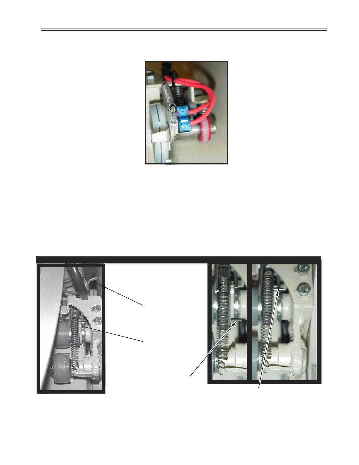
OVERSPEED
OVERSPEED SWITCH
If the overspeed switch trips, you must reset two levers: (1) the overspeed lever, and (2) the
cam lever.
NOTE: See the photos below for set and tripped lever positions
To reset the levers, first rotate overspeed switch lever. While rotating this lever, push in
on the wires to engage the overspeed switch. (If the lever is rotated too far, the switch will not be
reset.)
Rotate the cam lever just until you feel the switch engage.
LEVERS TO RESET IF OVERSPEED SWITCH TRIPS TOP VIEW
OVERSPEED
LEVER
CAM LEVER
(SHOWN IN SET
POSITION)
CAM LEVER
(SHOWN IN TRIPPED
POSITION)
(SHOWN IN SET POSITION)
CAM LEVER
SRE-2000 RES UL 08-16-2004
©2004,2001 BRUNO INDEPENDENT LIVING AIDS, INC.®47
Page 48

WIRING SCHEMATIC
©2004,2001 BRUNO INDEPENDENT LIVING AIDS, INC.® 48
SRE-2000 RES UL 08-16-2004
Page 49

CLAMP ASSEMBLIES
SRE-2000 RES UL 08-16-2004
©2004,2001 BRUNO INDEPENDENT LIVING AIDS, INC.®49
Page 50

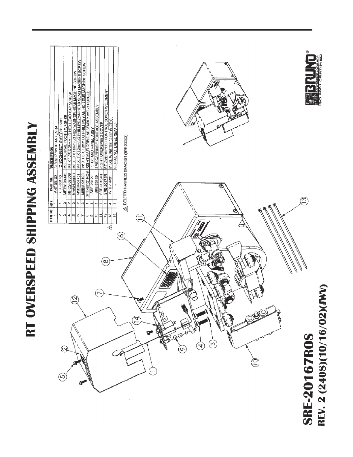
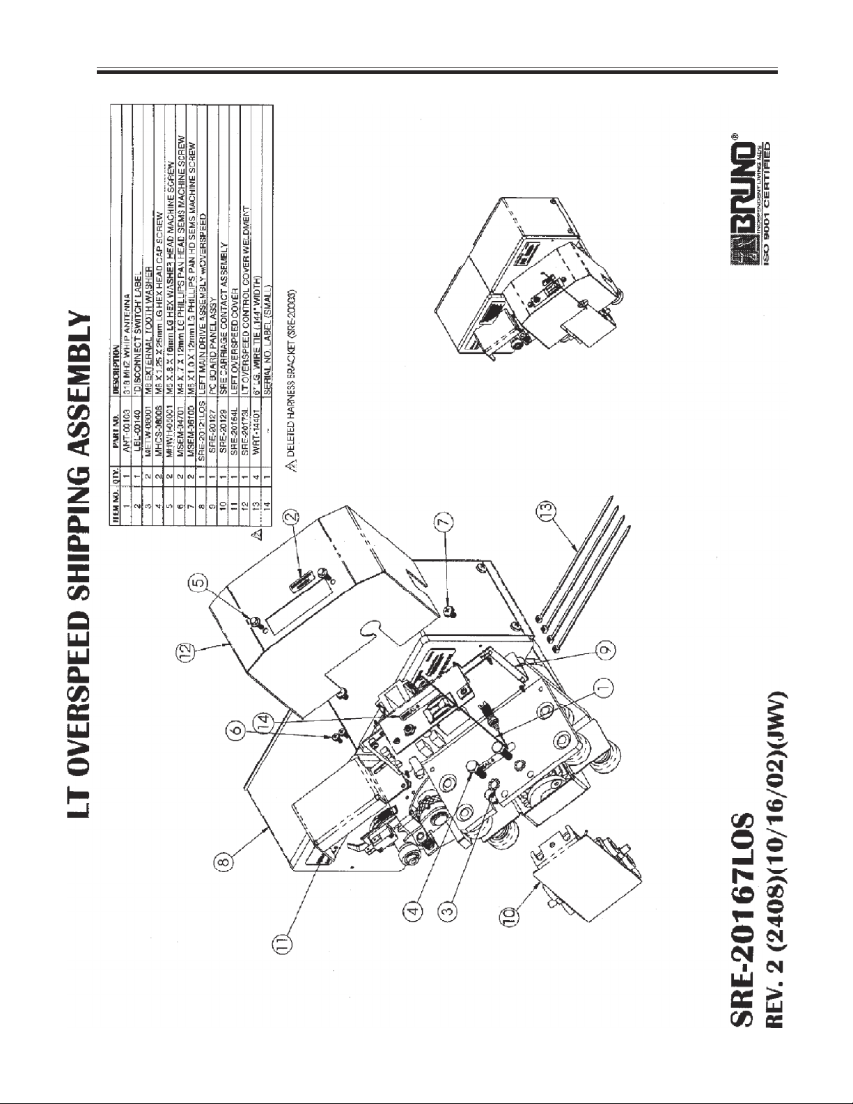
EXPLODED VIEWS WITH BILLS OF MATERIALS
©2004,2001 BRUNO INDEPENDENT LIVING AIDS, INC.® 50
SRE-2000 RES UL 08-16-2004
Page 51

EXPLODED VIEWS WITH BILLS OF MATERIALS
SRE-2000 RES UL 08-16-2004
©2004,2001 BRUNO INDEPENDENT LIVING AIDS, INC.®
Page 52

EXPLODED VIEWS WITH BILLS OF MATERIALS
©2004,2001 BRUNO INDEPENDENT LIVING AIDS, INC.® 52
SRE-2000 RES UL 08-16-2004
Page 53

EXPLODED VIEWS WITH BILLS OF MATERIALS
SRE-2000 RES UL 08-16-2004
©2004,2001 BRUNO INDEPENDENT LIVING AIDS, INC.®53
Page 54

EXPLODED VIEWS WITH BILLS OF MATERIALS
©2004,2001 BRUNO INDEPENDENT LIVING AIDS, INC.® 54
SRE-2000 RES UL 08-16-2004
Page 55

EXPLODED VIEWS WITH BILLS OF MATERIALS
SRE-2000 RES UL 08-16-2004
©2004,2001 BRUNO INDEPENDENT LIVING AIDS, INC.®55
Page 56

EXPLODED VIEWS WITH BILLS OF MATERIALS
©2004,2001 BRUNO INDEPENDENT LIVING AIDS, INC.® 56
SRE-2000 RES UL 08-16-2004
Page 57

EXPLODED VIEWS WITH BILLS OF MATERIALS
SRE-2000 RES UL 08-16-2004
©2004,2001 BRUNO INDEPENDENT LIVING AIDS, INC.®57
Page 58

EXPLODED VIEWS WITH BILLS OF MATERIALS
©2004,2001 BRUNO INDEPENDENT LIVING AIDS, INC.® 58
SRE-2000 RES UL 08-16-2004
Page 59

EXPLODED VIEWS WITH BILLS OF MATERIALS
SRE-2000 RES UL 08-16-2004
©2004,2001 BRUNO INDEPENDENT LIVING AIDS, INC.®59
Page 60
EXPLODED VIEWS WITH BILLS OF MATERIALS
©2004,2001 BRUNO INDEPENDENT LIVING AIDS, INC.® 60
SRE-2000 RES UL 08-16-2004
Page 61
EXPLODED VIEWS WITH BILLS OF MATERIALS
SRE-2000 RES UL 08-16-2004
©2004,2001 BRUNO INDEPENDENT LIVING AIDS, INC.®61
Page 62

EXPLODED VIEWS WITH BILLS OF MATERIALS
©2004,2001 BRUNO INDEPENDENT LIVING AIDS, INC.® 62
SRE-2000 RES UL 08-16-2004
Page 63

EXPLODED VIEWS WITH BILLS OF MATERIALS
SRE-2000 RES UL 08-16-2004
©2004,2001 BRUNO INDEPENDENT LIVING AIDS, INC.®63
Page 64

EXPLODED VIEWS WITH BILLS OF MATERIALS
©2004,2001 BRUNO INDEPENDENT LIVING AIDS, INC.® 64
SRE-2000 RES UL 08-16-2004
Page 65

EXPLODED VIEWS WITH BILLS OF MATERIALS
SRE-2000 RES UL 08-16-2004
©2004,2001 BRUNO INDEPENDENT LIVING AIDS, INC.®65
Page 66

EXPLODED VIEWS WITH BILLS OF MATERIALS
©2004,2001 BRUNO INDEPENDENT LIVING AIDS, INC.® 66
SRE-2000 RES UL 08-16-2004
Page 67

EXPLODED VIEWS WITH BILLS OF MATERIALS
SRE-2000 RES UL 08-16-2004
©2004,2001 BRUNO INDEPENDENT LIVING AIDS, INC.®67
Page 68

EXPLODED VIEWS WITH BILLS OF MATERIALS
©2004,2001 BRUNO INDEPENDENT LIVING AIDS, INC.® 68
SRE-2000 RES UL 08-16-2004
Page 69

EXPLODED VIEWS WITH BILLS OF MATERIALS
SRE-2000 RES UL 08-16-2004
©2004,2001 BRUNO INDEPENDENT LIVING AIDS, INC.®69
Page 70

EXPLODED VIEWS WITH BILLS OF MATERIALS
©2004,2001 BRUNO INDEPENDENT LIVING AIDS, INC.® 70
SRE-2000 RES UL 08-16-2004
Page 71

EXPLODED VIEWS WITH BILLS OF MATERIALS
SRE-2000 RES UL 08-16-2004
©2004,2001 BRUNO INDEPENDENT LIVING AIDS, INC.®71
Page 72

EXPLODED VIEWS WITH BILLS OF MATERIALS
©2004,2001 BRUNO INDEPENDENT LIVING AIDS, INC.® 72
SRE-2000 RES UL 08-16-2004
Page 73

EXPLODED VIEWS WITH BILLS OF MATERIALS
SRE-2000 RES UL 08-16-2004
©2004,2001 BRUNO INDEPENDENT LIVING AIDS, INC.®73
Page 74

EXPLODED VIEWS WITH BILLS OF MATERIALS
©2004,2001 BRUNO INDEPENDENT LIVING AIDS, INC.® 74
SRE-2000 RES UL 08-16-2004
Page 75

EXPLODED VIEWS WITH BILLS OF MATERIALS
SRE-2000 RES UL 08-16-2004
©2004,2001 BRUNO INDEPENDENT LIVING AIDS, INC.®75
Page 76

EXPLODED VIEWS WITH BILLS OF MATERIALS
©2004,2001 BRUNO INDEPENDENT LIVING AIDS, INC.® 76
SRE-2000 RES UL 08-16-2004
Page 77

EXPLODED VIEWS WITH BILLS OF MATERIALS
SRE-2000 RES UL 08-16-2004
©2004,2001 BRUNO INDEPENDENT LIVING AIDS, INC.®77
Page 78

EXPLODED VIEWS WITH BILLS OF MATERIALS
©2004,2001 BRUNO INDEPENDENT LIVING AIDS, INC.® 78
SRE-2000 RES UL 08-16-2004
Page 79

EXPLODED VIEWS WITH BILLS OF MATERIALS
SRE-2000 RES UL 08-16-2004
©2004,2001 BRUNO INDEPENDENT LIVING AIDS, INC.®79
Page 80

EXPLODED VIEWS WITH BILLS OF MATERIALS
©2004,2001 BRUNO INDEPENDENT LIVING AIDS, INC.® 80
SRE-2000 RES UL 08-16-2004
Page 81

EXPLODED VIEWS WITH BILLS OF MATERIALS
SRE-2000 RES UL 08-16-2004
©2004,2001 BRUNO INDEPENDENT LIVING AIDS, INC.®81
Page 82

EXPLODED VIEWS WITH BILLS OF MATERIALS
©2004,2001 BRUNO INDEPENDENT LIVING AIDS, INC.® 82
SRE-2000 RES UL 08-16-2004
Page 83

EXPLODED VIEWS WITH BILLS OF MATERIALS
SRE-2000 RES UL 08-16-2004
©2004,2001 BRUNO INDEPENDENT LIVING AIDS, INC.®83
Page 84

EXPLODED VIEWS WITH BILLS OF MATERIALS
©2004,2001 BRUNO INDEPENDENT LIVING AIDS, INC.® 84
SRE-2000 RES UL 08-16-2004
Page 85

EXPLODED VIEWS WITH BILLS OF MATERIALS
SRE-2000 RES UL 08-16-2004
©2004,2001 BRUNO INDEPENDENT LIVING AIDS, INC.®85
Page 86

EXPLODED VIEWS WITH BILLS OF MATERIALS
©2004,2001 BRUNO INDEPENDENT LIVING AIDS, INC.® 86
SRE-2000 RES UL 08-16-2004
Page 87

EXPLODED VIEWS WITH BILLS OF MATERIALS
SRE-2000 RES UL 08-16-2004
©2004,2001 BRUNO INDEPENDENT LIVING AIDS, INC.®87
Page 88

EXPLODED VIEWS WITH BILLS OF MATERIALS
©2004,2001 BRUNO INDEPENDENT LIVING AIDS, INC.® 88
SRE-2000 RES UL 08-16-2004
Page 89

EXPLODED VIEWS WITH BILLS OF MATERIALS
SRE-2000 RES UL 08-16-2004
©2004,2001 BRUNO INDEPENDENT LIVING AIDS, INC.®89
Page 90

TROUBLESHOOTING
Check circuit breaker. Reset if necessary.
UNIT FAILS TO
OPERATE
Check battery connections.
Check footrest safety switches to see if one of these limit
switches is depressed. Sliding safety tray below footrest should
slide freely and should not stick in a position which would
depress one of the safety switches.
Check for discharged batteries. Battery
voltage should fall within the range of 16-28 VDC.
Check for discharged batteries.
Check setting of speed control potentiometer.
UNIT OPERATES
SLOWLY, LACKS
POWER
CONTROLS OPERATE
BACKWARDS AND UNIT
GOES "UP" SLOWLY
AND "DOWN" FASTER
UNIT OPERATES
ERRATICALLY OR
INTERMITTENTLY
.
WITH REMOTE
CALL/SEND
Check for loose connections.
Check to make sure charger is plugged in and working.
Unit has been connected for left-hand operation but is installed
on the right-hand side of the stairs (or vice versa).
Connect according to instructions in the installation manual
Check all safety mechanisms, including swivel seat
safety switch.
Change the delay setting on the receiver board to 900 mSec.
Reorient the transmitter (to point directly at the carriage).
Consult your dealer, an experienced technician or call
our Technical Service Department at 1-800-882-8768.
©2004,2001 BRUNO INDEPENDENT LIVING AIDS, INC.® 90
SRE-2000 RES UL 08-16-2004
Page 91

TROUBLESHOOTING
Check swivel seat safety switch.
UNIT OPERATES
ERRATICALLY OR
INTERMITTENTLY
WITH A RIDER USING
THE ARMREST
MOUNTED CONTROL
SWITCH
UNIT WILL NOT
OPERATE UNLESS THE
SEAT IS POSITIONED SO
THAT IT FACES THE
OPEN SIDE OF THE
STAIRS
UNIT WILL NOT
OPERATE WITH
CALL / SEND
REMOTE
Check to see that the footrest safety tray is not dragging on
the stair nosing or hitting debris on the stairs.
Iif necessary, reposition the stair rail mounting brackets to
correct the problem.
Check the rail for debris that may bump safety switches
(footrest and carriage panels).
This is correct lift operation.
A safety switch in the seat swivel prevents the unit from
operating with the seat "out of position".
Check batteries in remote call/send unit.
Aim transmiter at the carriage
Transmitters must be `learned' to receiver.
UNIT DOES NOT SHUT
OFF WHEN IT HITS THE
BUMPER AT THE END
OF THE RAIL
ROUGH OR
CHATTERING RIDE
SRE-2000 RES UL 08-16-2004
Connections were not made correctly when changing unit from
left-side to right-side installation. Consult installation manual for
diagram of correct wiring configuration.
Verify correct operation of limit switch in carriage assembly.
Wipe down rail.
Apply a small amount of grease to the gear rack only.
©2004,2001 BRUNO INDEPENDENT LIVING AIDS, INC.®91
Page 92

FIVE YEAR MAJOR COMPONENTS WARRANTY
TWO YEAR LIMITED WARRANTY
for
Bruno Stairlifts
Bruno Independent Living Aids, Inc. (Bruno), warrants to the original purchaser of a Bruno
Stairlift that the Bruno Stairlift is free from defects in material and workmanship for a period of
two years from date of purchase. In addition, Bruno warrants that the motor, gear box and rail
(the Major Components) will be free from defects in materials and workmanship for a period of
five years from the date of purchase.
The exclusive remedy for a defect in a Bruno Stairlift shall be the repair or replacement, at the
option of Bruno, of the defective part or component. After the first 30 days of this warranty, only
parts and components are covered. This warranty does not cover labor and other services after
the initial 30 days. If repair or replacement of a Bruno Stairlift is not commercially practical or
cannot be timely made, Bruno may elect to refund the purchase price of the Bruno Stairlift
instead of repairing or replacing the Bruno Stairlift.
IN NO EVENT SHALL BRUNO BE RESPONSIBLE FOR INDIRECT, INCIDENTAL OR
CONSEQUENTIAL DAMAGES, WHETHER SUCH DAMAGES ARISE FROM CLAIMS BASED
ON CONTRACT, WARRANTY, TORT (INCLUDING NEGLIGENCE), STRICT LIABILITY OR
PRODUCT LIABILITY. Some states do not allow the exclusion or limitation of incidental or
consequential damages, so the above limitation or exclusion may not apply to you.
ALL IMPLIED WARRANTIES, INCLUDING ANY WARRANTY OF MERCHANTABILITY OR
FITNESS FOR A PARTICULAR PURPOSE, ARE LIMITED IN THEIR DURATION TO THE
LENGTH OF THE WARRANTY STATED ABOVE FOR THE AFFECTED COMPONENT. Some
states do not allow limitations on how long an implied warranty lasts so the above limitation may
not apply to you.
To obtain warranty service, you must follow these procedures:
1. Obtain return authorization by calling your local Bruno dealer or Bruno at
1-800-882-8768;
2. Return the Bruno Stairlift, freight prepaid, to the address provided by your
Bruno dealer or Bruno with proof of purchase indicating the date purchased.
Bruno will pay for shipping back to the purchaser within the continental United States and
Canada if a defect in material or workmanship is discovered. Return freight and repair charges
will be the responsibility of the purchaser if the problem is not covered by warranty.
This warranty does not cover damage or failure caused by misuse, abuse, accidents, physical
damage, modifications not made by Bruno, damage in shipment, or repairs undertaken by
anyone other than Bruno factory employees or authorized distributors. The original purchaser
of a Bruno Stairlift that is leased or rented shall be the person or entity acting as the lessee or
rental provider.
This warranty gives you specific legal rights, and you may also have other rights which vary
from state to state. Bruno specifically does not authorize any person to extend the time or
scope of this warranty.
For further information regarding this limited warranty, please contact Bruno by calling
1-800-882-8768 or writing to Bruno at the following address:
Bruno Independent Living Aids, Inc.
Attention: Service Department
1780 Executive Drive, Post Office Box 84
Oconomowoc, WI 53066 USA
©2004,2001 BRUNO INDEPENDENT LIVING AIDS, INC.® 92
SRE-2000 RES UL 08-16-2004
 Loading...