

Page 1
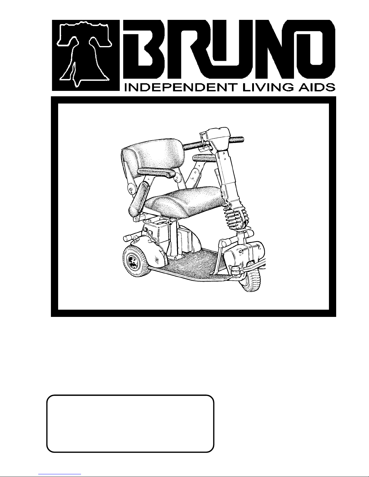
THE REGAL CUB 35 3 WHEEL FWD
TM
*ILLUSTRATION SHOWS REGAL CUB WITH
DELUXE SEAT AND FRONT BUMPER OPTIONS
1780 EXECUTIVE DR., P.O., BOX 84
OCONOMOWOC, WI 53066
(262) 567-4990
FAX: (262) 567-4341
OPERATORS MANUAL
TOLLFREE
TECHNICAL SERVICE (INSTALLATION, & WARRANTY ASSISTANCE): 1-800-882-8768
email: service@bruno.com
APPLICATIONS, CUSTOMER SERVICE & SALES:
BOTH TOLLFREE NUMBERS ARE GOOD THROUGHOUT THE U.S. AND CANADA
TOLLFREE
1-800-882-8183
DEALER :
MAN-CUB-3
REVISED 01-02-2001
Page 2

2
© 2000 BRUNO INDEPENDENT LIVING AIDS, INC.
Page 3

TABLE OF CONTENTS
COVER.............................................................................................................................. 1
TABLE OF CONTENTS.................................................................................................... 3
CE SPECIFICATIONS....................................................................................................... 4
PREFACE.......................................................................................................................... 5
IMPORTANT SAFETY TIPS.......................................................................................6 - 9
SEAT ADJUSTMENT
SEAT POST.......................................................................................10
SEAT SWIVEL...................................................................................11
DELUXE SEAT ANGLE ADJUSTMENT............................................11
FLIP-UP ARMRESTS........................................................................ 11
BACKREST HEIGHT ADJUSTMENT................................................12
SEAT CUSHION DEPTH ADJUSTMENT..........................................12
MULTIPLE LEVER POSITIONING.................................................... 13
DELUXE SEAT PLATE INSTALLATION........................................... 14
WHEEL ADJUSTMENT.....................................................................................................15
ADJUSTING TENSION IN CHAIN.....................................................................................16
BATTERY INFORMATION........................................................................................17 - 20
OPERATION
TILLER ADJUSTMENT..................................................................... 21
TILLER OPERATION........................................................................ 22
SPEED LIMITER SWITCH ADJUSTMENT....................................... 23
BOARDING YOUR SCOOTER......................................................... 24
BRAKING.......................................................................................... 24
BATTERY CONDITION..................................................................... 25
FILLING TIRES WITH AIR................................................................ 25
MAXIMUM RECOMMENDED INCLINE.............................................26
MANUAL REAR WHEEL BRAKE.................................................................................... 27
TRANSPORTING YOUR REGAL CUB............................................................................ 28
SWITCHING THUMB CONTROL DIRECTION................................................................. 29
SCOOTER MAINTENANCE.............................................................................................. 30
AVAILABLE OPTIONS..............................................................................................31 - 40
SCHEMATIC DIAGRAM.................................................................................................... 41
EMI AND RFI INFORMATION...................................................................................42 - 44
TROUBLESHOOTING.............................................................................................45 & 46
LOWER TILLER ASSEMBLY............................................................................................47
UPPER TILLER ASSEMBLY.............................................................................................48
COMPLETE TILLER ASSEMBLY.....................................................................................49
UPPER DELTA TILLER ASSEMBLY................................................................................50
COMPLETE DELTA TILLER ASSEMBLY........................................................................ 51
EXPLODED VIEW............................................................................................................. 52
EXPLODED VIEW............................................................................................................. 53
17" / 20" / 22" UPHOLSTERED ARMREST ASSEMBLIES............................................. 54
LEFT & RIGHT SEAT HINGE ASSEMBLY....................................................................... 55
SEAT OPTIONS................................................................................................................ 56
SEAT OPTIONS.................................................................................................................57
EXPLODED VIEW (CUB OPTIONS)................................................................................. 58
EXPLODED VIEW (CUB POWER SEAT)......................................................................... 60
PARTS LISTING (CUB POWER SEAT)............................................................................ 61
LIMITED WARRANTY....................................................................................................... 62
3
© 2000 BRUNO INDEPENDENT LIVING AIDS, INC.
Page 4

4
© 2001 BRUNO INDEPENDENT LIVING AIDS, INC.
Page 5

PREFACE
Thank you for purchasing a new REGAL CUB 35 by Bruno. We are confident your new
REGAL CUB will open many doors for mobility and independence.
This manual is designed to instruct you in the proper care and use of your scooter and to
answer questions frequently asked by our customers. Please read all sections of this
manual so that you will be able to safely use your REGAL CUB'S many features and understand how to care for it in a way which will promote years of economical, reliable
service.
5
REVISED 01-02-2000
© 2001 BRUNO INDEPENDENT LIVING AIDS, INC.
Page 6
6
SAFETY
CAUTION:
DO NOT OPERATE
YOUR SCOOTER
WHEN PARKING
BRAKE IS OFF
SAFE OPERATING PROCEDURE
FOR YOUR SAFETY AND TO AVOID POSSIBLE DAMAGE
TO YOUR REGAL CUB, IT IS EXTREMELY IMPORTANT TO
OBSERVE THE FOLLOWING RULES.
DO
1. Lock the (optional) 360 degrees seat swivel plate
when operating your REGAL CUB. NOTE: The
standard 90 degree swivel plate has an automatic
locking mechanism.
2. Pull Key Jack to "off" position before getting on and
off your vehicle.
3. Come to a complete stop before attempting reverse
direction.
4. Approach curbs, bumps, and other obstructions
very slowly.
© 2001 BRUNO INDEPENDENT LIVING AIDS, INC.
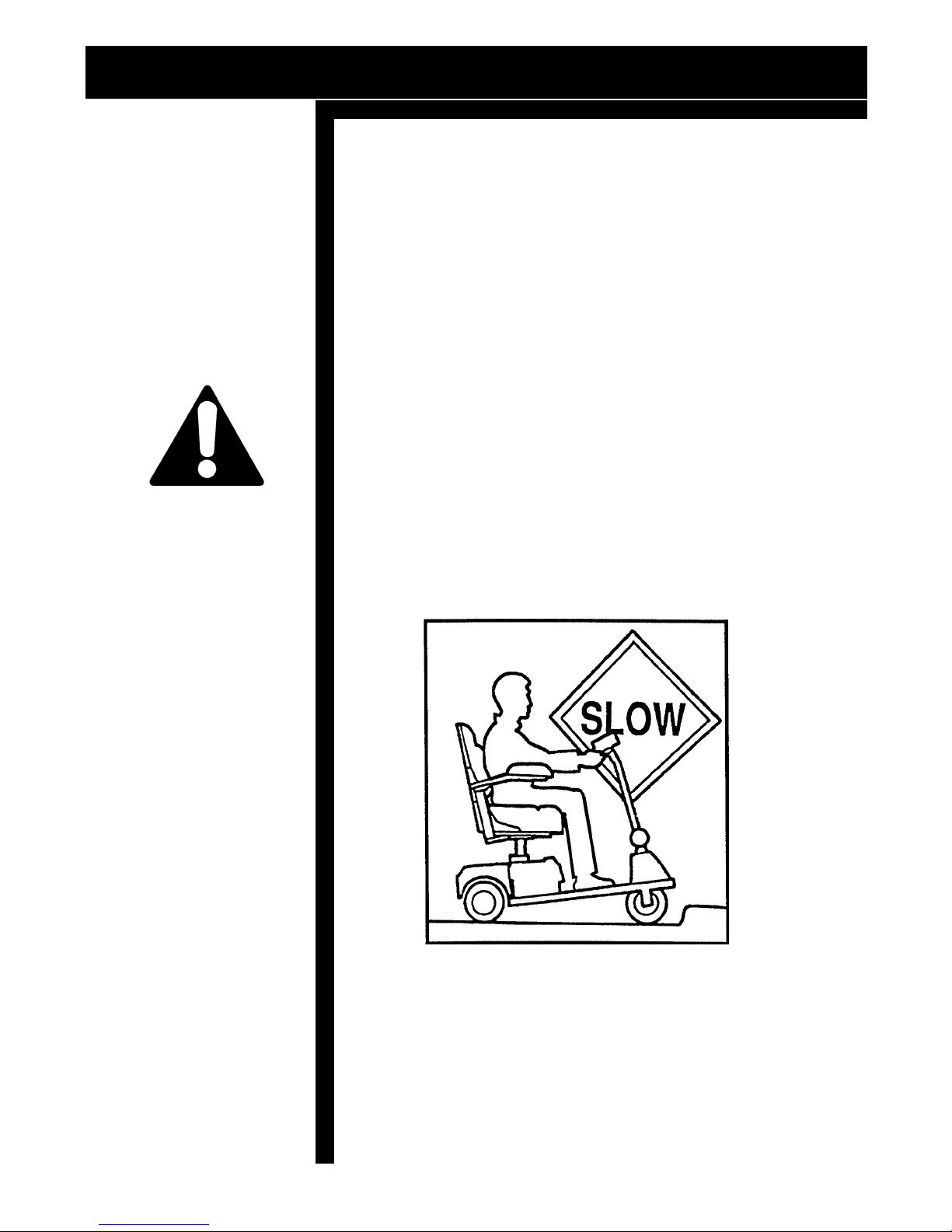
5. Drive slowly and have an assistant help you during
the initial training period.
Page 7
SAFETY
6. For additional stability, keep the seating height adjusted
at the lowest comfortable position. Have the rear wheels
extended to widest position for your traveling conditions.
7. When traveling outside, have rear wheels in widest
setting. This greatly increases your stability.
8. Always disconnect the batteries before servicing your
REGAL CUB.
9. Notice what type of surface you are riding on (i.e. Is the
grass wet?) and adjust speed accordingly.
ON
7
OFF
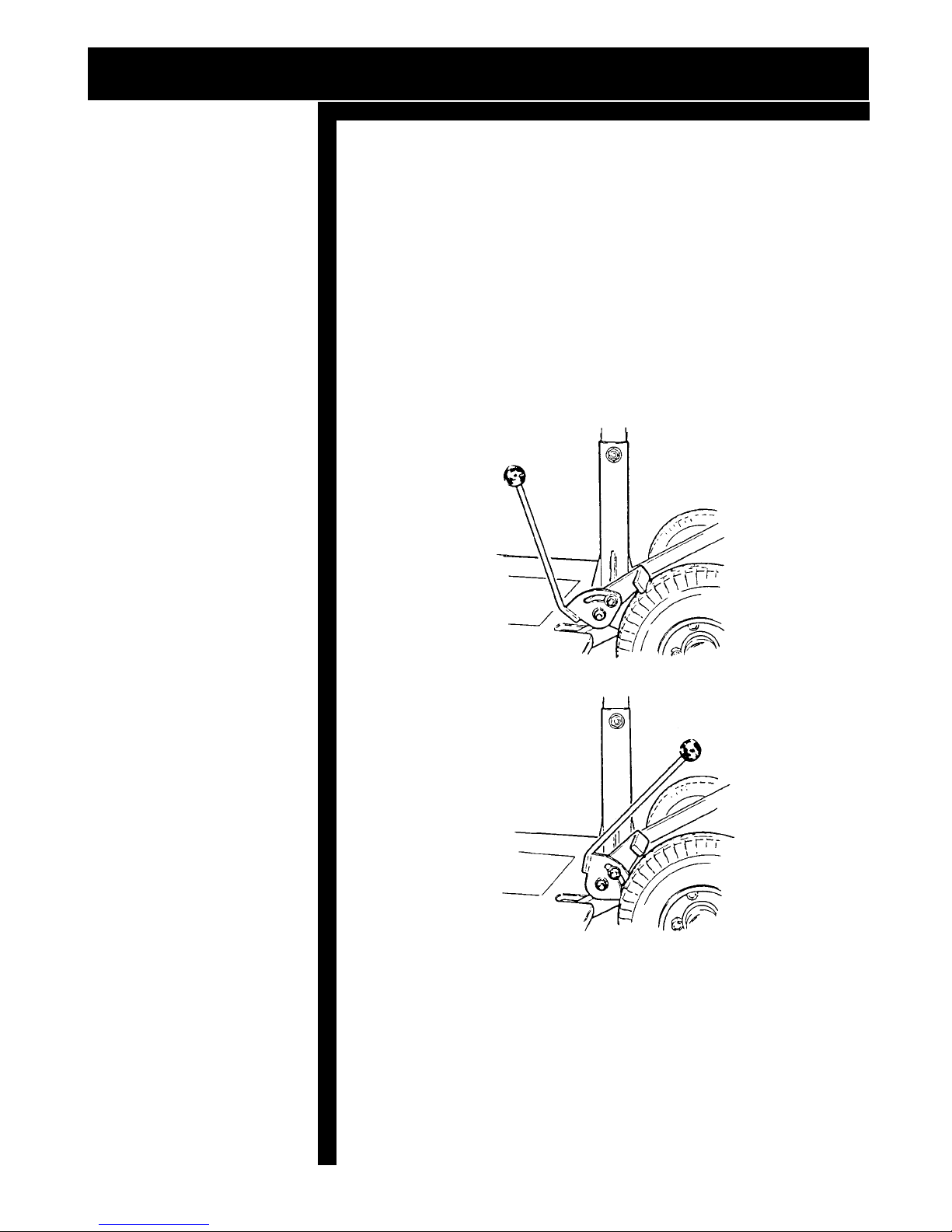
10. When stopping on an incline use the manual parking
brake located on the left or right side near the rear wheel.
Push the lever forward until the brake is engaged.
© 2001 BRUNO INDEPENDENT LIVING AIDS, INC.
Page 8
8
SAFETY
CAUTION:
CLEAN YOUR
REGAL CUB WITH A
DAMP CLOTH OR
SPONGE. DO NOT
USE ABRASIVE
CLEANERS WHICH
WILL DAMAGE THE
FINISH. DO NOT
ATTEMPT TO "HOSE
IT OFF" OR CLEAN
IT WITH STEAM OR
A HIGH PRESSURE
WASHER AS THIS
MAY CAUSE SERIOUS ELECTRICAL
MALFUNCTION.
SAFE OPERATING PROCEDURE
DO NOT
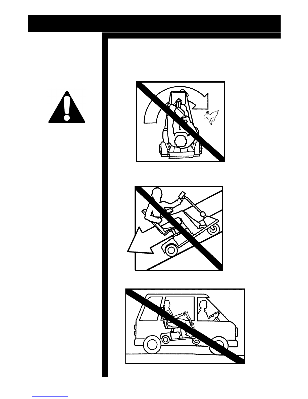
1. Do not make sharp turns at high speeds as it could
result in tipping.
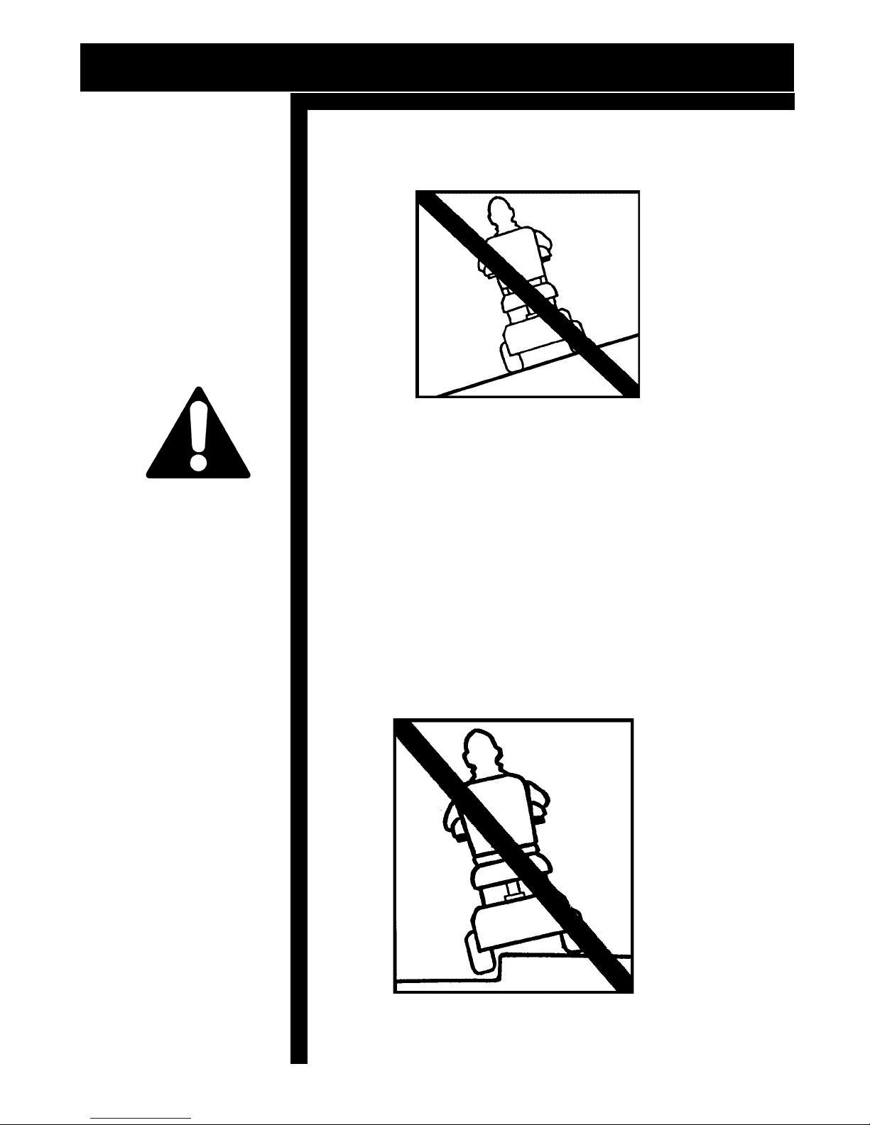
2. Do not back down inclines as it may result in
overturning.
© 2001 BRUNO INDEPENDENT LIVING AIDS, INC.
3. Do not sit on the REGAL CUB in a moving vehicle.
Page 9
SAFETY
SAFE OPERATING PROCEDURE
4. Do not travel crosswise on an incline as you may tip
over.
9
CAUTION:
ALWAYS REMOVE
THE KEY SO THE
POWER IS "OFF"
BEFORE MOUNTING
OR DISMOUNTING
THE SCOOTER,
ESPECIALLY ON AN
INCLINE.
CAUTION:
DO NOT RIDE
SCOOTER
BAREFOOT
5. Do not turn abruptly when traveling up or down an
incline as it may cause tipping.
6. Do not allow anyone to ride with you on your
REGAL CUB.
7. Do not operate your REGAL CUB near stairs, steps,
curbs or terraces where you might inadvertently
drop a wheel off the edge of a step.
© 2001 BRUNO INDEPENDENT LIVING AIDS, INC.
Page 10
10
HINT:
IF YOU ARE
ADJUSTING OR
REMOVING YOUR
SEAT POST
FREQUENTLY - THE
OPTIONAL QUICK
RELEASE PIN WOULD
BE OF GREAT
ASSISTANCE.
SEAT ADJUSTMENT
SEAT HEIGHT ADJUSTMENT
Your REGAL CUB seat has several adjustments for
comfort and safety.
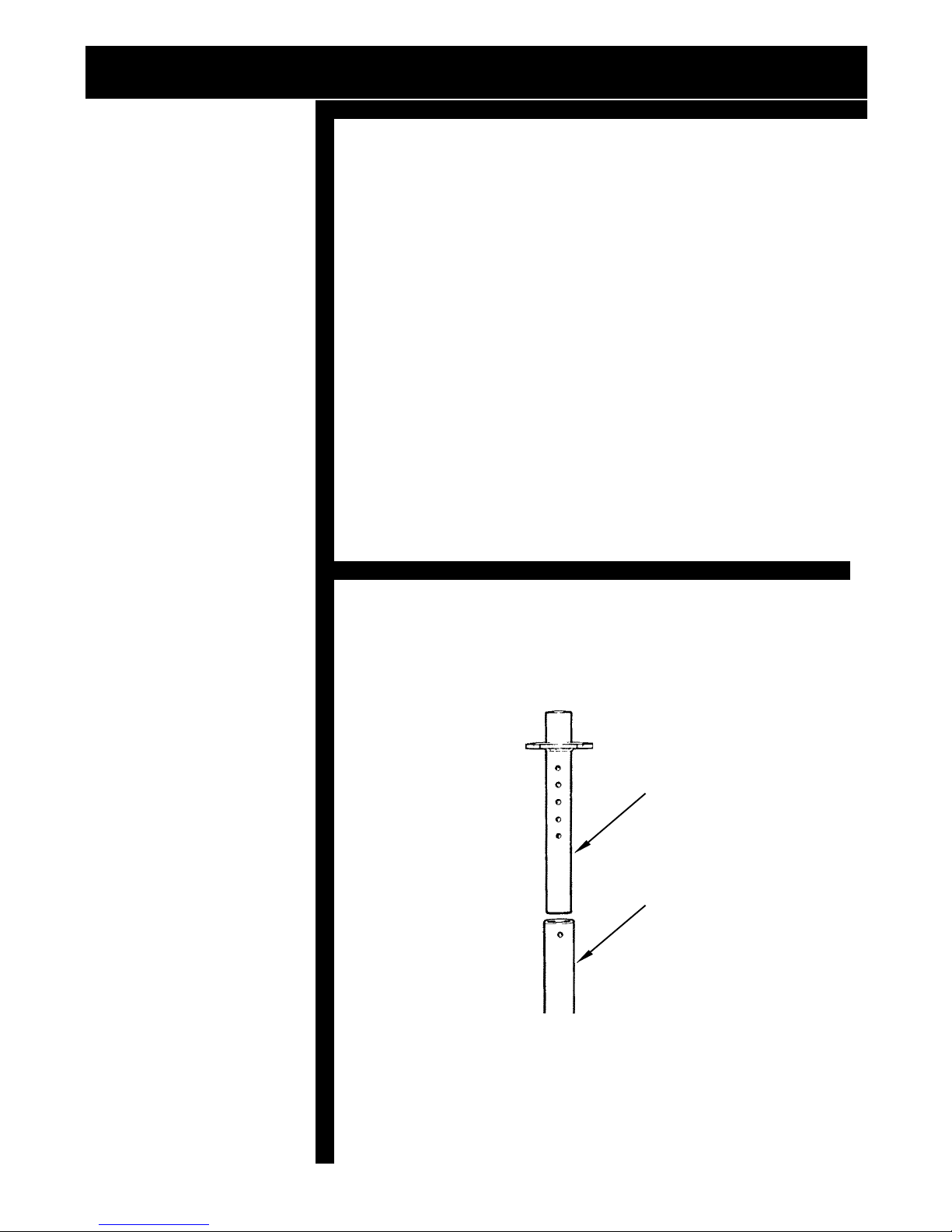
Five holes are provided in the seat post to allow five seat
height adjustments.
To adjust seat height:
1. Lift the Seat off the Seat post.
2. Remove the 3/8-16 x 2.5" hex head cap screw from
the seat post.
3. Raise or lower the seat post, as desired, and replace
the bolt. CAUTION: Do not over tighten the bolt as
this will distort the Seat post and outer Seat post
tube. Note: The dealer should make this adjustment
at the time of purchase.
FIGURE 1
SEAT HEIGHT ADJUSTMENT
INNER SEAT POST
OUTER SEAT POST
© 2001 BRUNO INDEPENDENT LIVING AIDS, INC.
Page 11
SEAT ADJUSTMENT
SEAT SWIVEL
Your REGAL CUB'S seat is designed to swivel 360 degrees
and can be locked every 90 degrees. Pushing the seat
swivel lever forward releases the swivel clamp and allows
you to rotate to the next 90 degree increment, the seat will
automatically lock securely in place. *The swivel plate can
be set up to release the seat swivel by pushing the seat
swivel lever backward. (*SEE PAGE 9) Repeat until the
desired position is obtained. NOTE: If swivel locking in
other than 90 degree increments is desired, an optional 360
degree swivel, which can be locked in any position, is available.
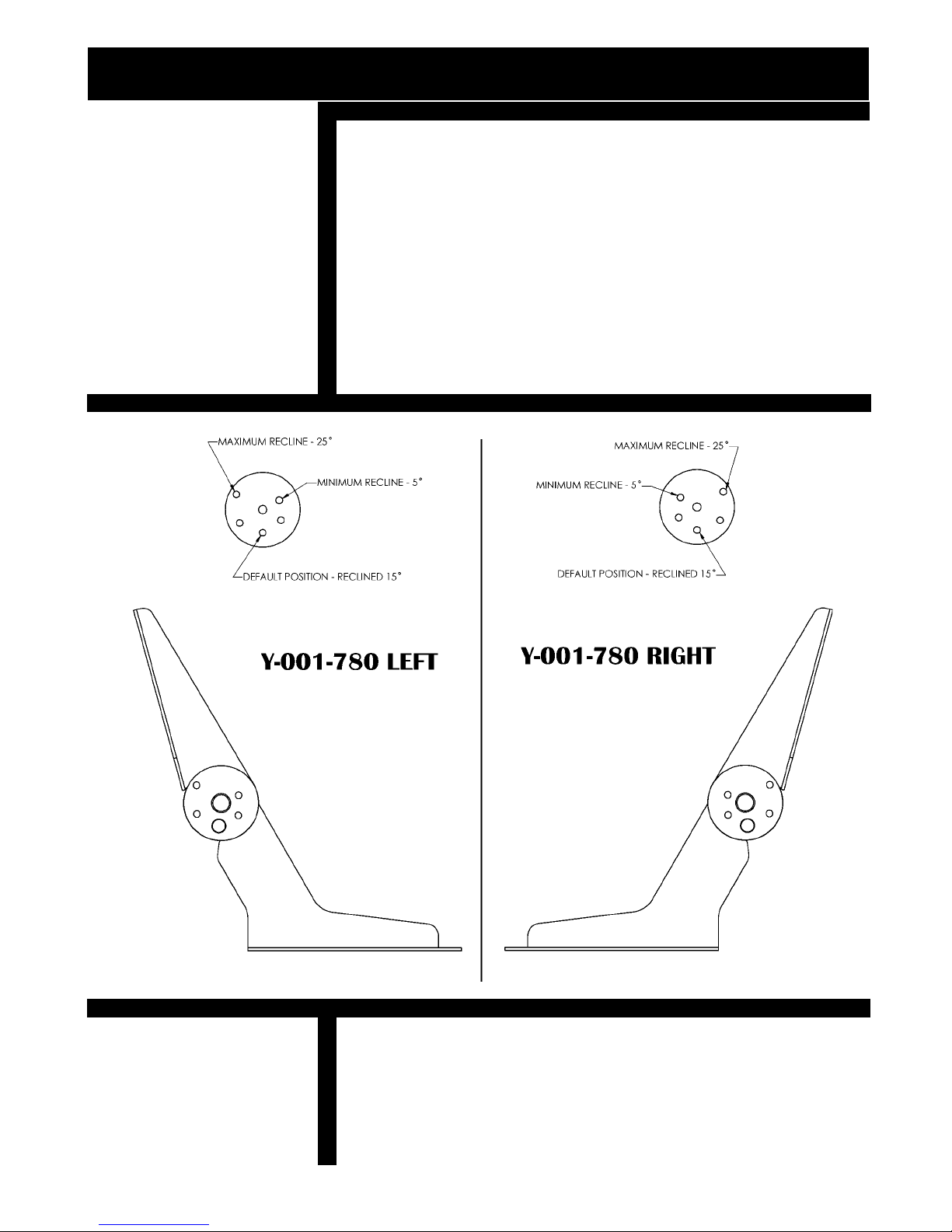
DELUXE SEAT ANGLE ADJUSTMENT
11
FLIP-UP ARMRESTS
The deluxe seat features flip-up armrests for easy entry and
exit from the scooter.
© 2001 BRUNO INDEPENDENT LIVING AIDS, INC.
Page 12
12
SEAT ADJUSTMENT
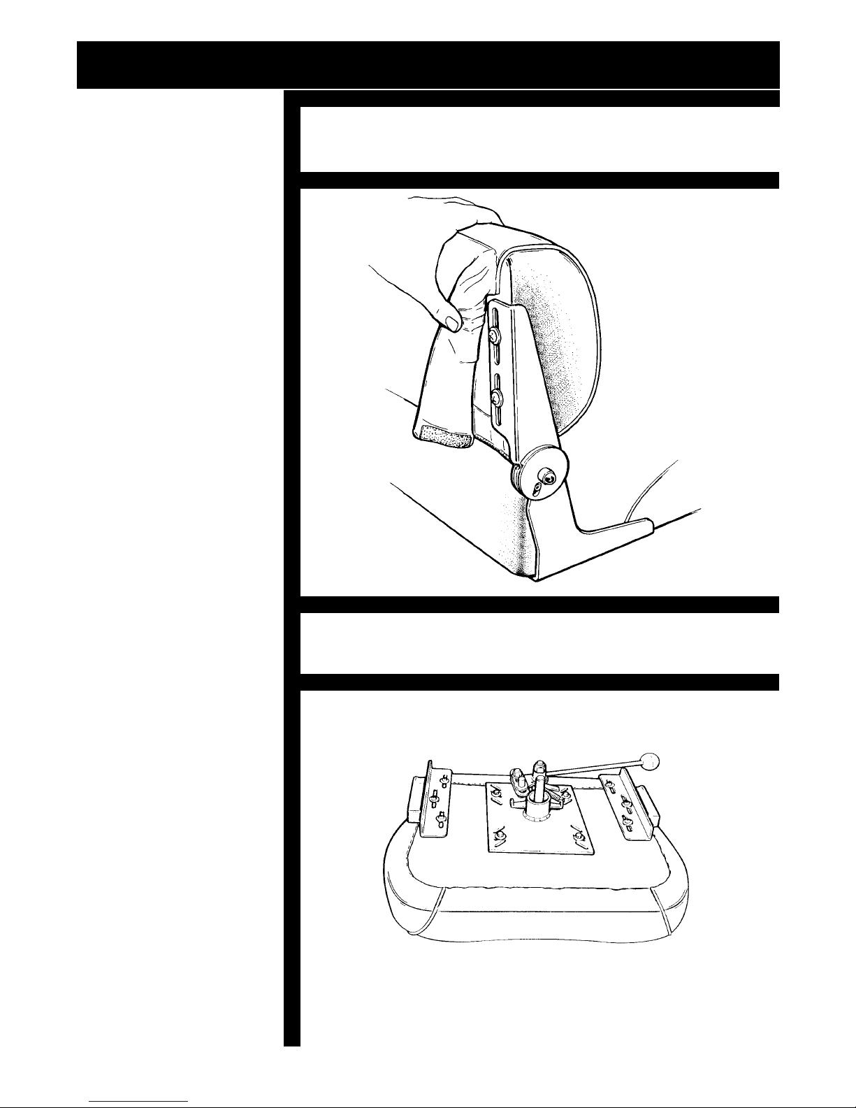
BACKREST HEIGHT (DELUXE SEAT ONLY)
The slotted Backrest Support Brackets allow three-inches
of Backrest Height Adjustment.
PEEL BACK FABRIC TO ADJUST SEAT HEIGHT
SEAT CUSHION DEPTH (DELUXE SEAT ONLY)
Slots in the Seat Cushion Mounting Brackets allow three
inches of Seat Depth Adjustment.
SEAT CUSHION ADJUSTMENT
© 2001 BRUNO INDEPENDENT LIVING AIDS, INC.
Page 13
SEAT ADJUSTMENT
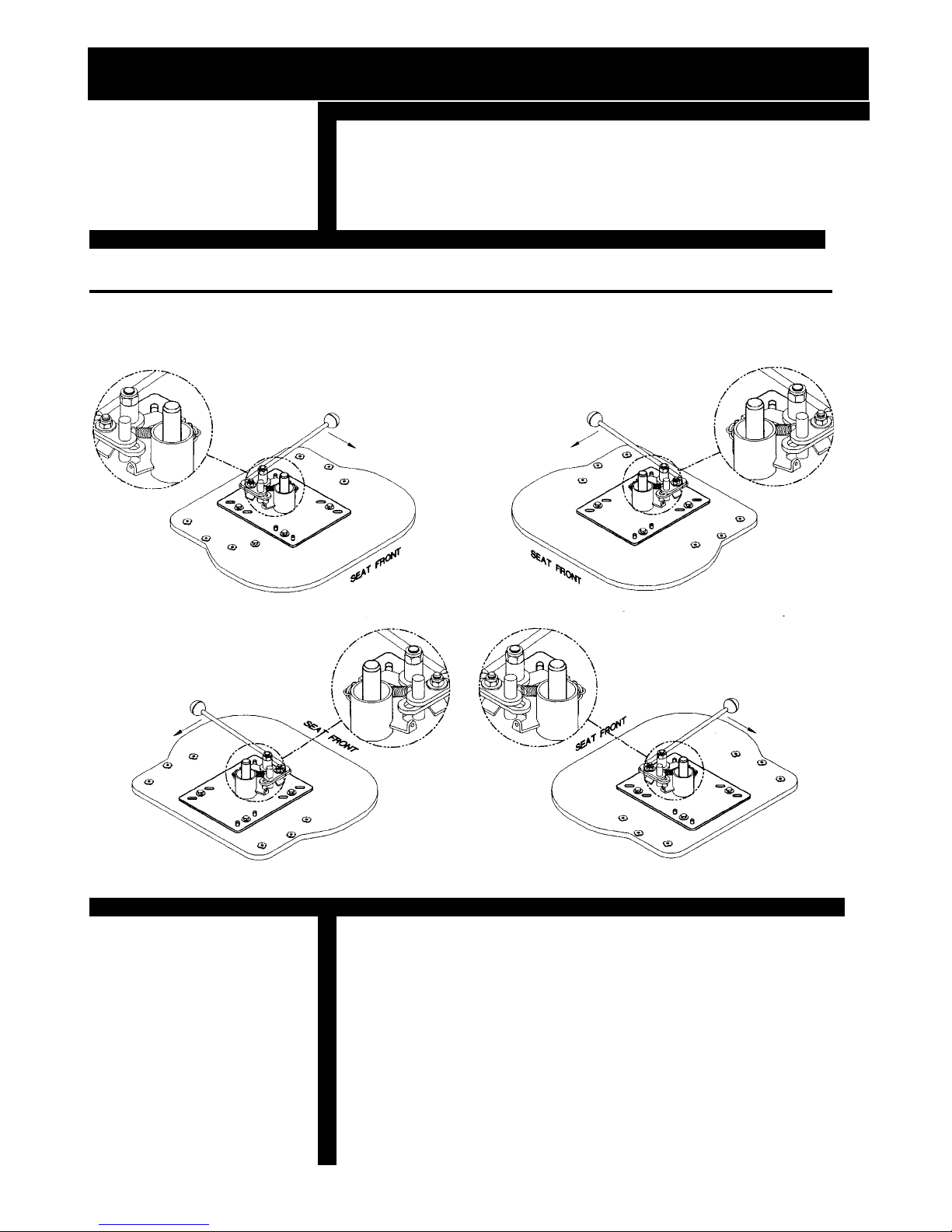
MULTIPLE LEVER POSITIONING
Install the seat plate with user comfort and convenience in
mind. The swivel lever is designed to be installed on the
right or the left, front and rear of the seat as shown in the
following diagram
MULTIPLE LEVER POSITIONING
RIGHT HANDED REAR LEVER POSITION LEFT HANDED REAR LEVER POSITION
13
RIGHT HANDED FRONT LEVER POSITIION LEFT HANDED FRONT LEVER POSITIION
Your REGAL CUB'S seat has three sets of slots for
forward, middle and back seat adjustment. Seat position
may be changed by repositioning the four bolts located on
the bottom of the seat as shown on following page.
NOTE: THE SEAT AND TILLER SHOULD BE POSITIONED
FOR MAXIMUM USER COMFORT AND CONVENIENCE. IN
THE INTEREST OF SAFETY AND STABILITY, ADJUST THE
SEAT TO THE LOWEST MOST FORWARD COMFORTABLE
POSITION.
© 2001 BRUNO INDEPENDENT LIVING AIDS, INC.
Page 14
14
SEAT ADJUSTMENT
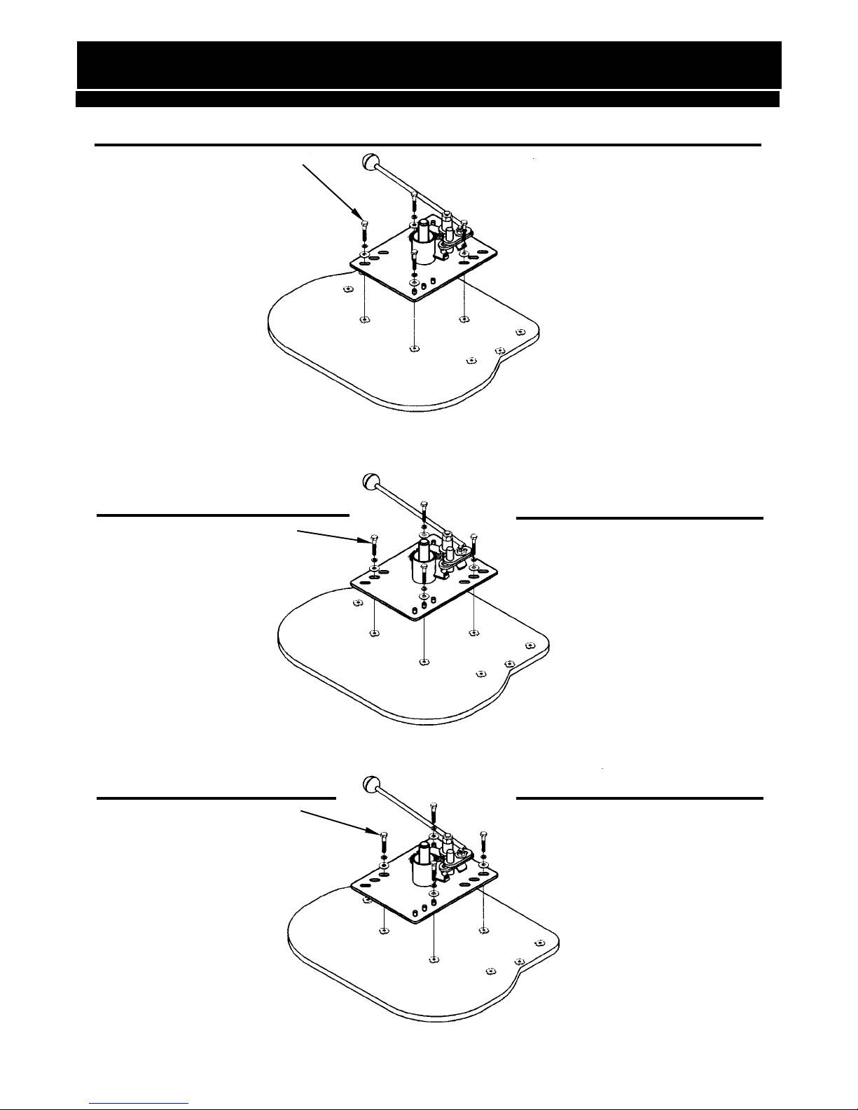
SEAT PLATE INSTALLATION - DELUXE SEAT
1/4-20 X 1' LG BOLT SEAT IN FORWARD POSITION
1/4-20 X 1' LG BOLT
1/4-20 X 1' LG BOLT
SEAT IN CENTER POSITION
SEAT IN REAR POSITION
© 2001 BRUNO INDEPENDENT LIVING AIDS, INC.
Page 15
WHEEL ADJUSTMENT
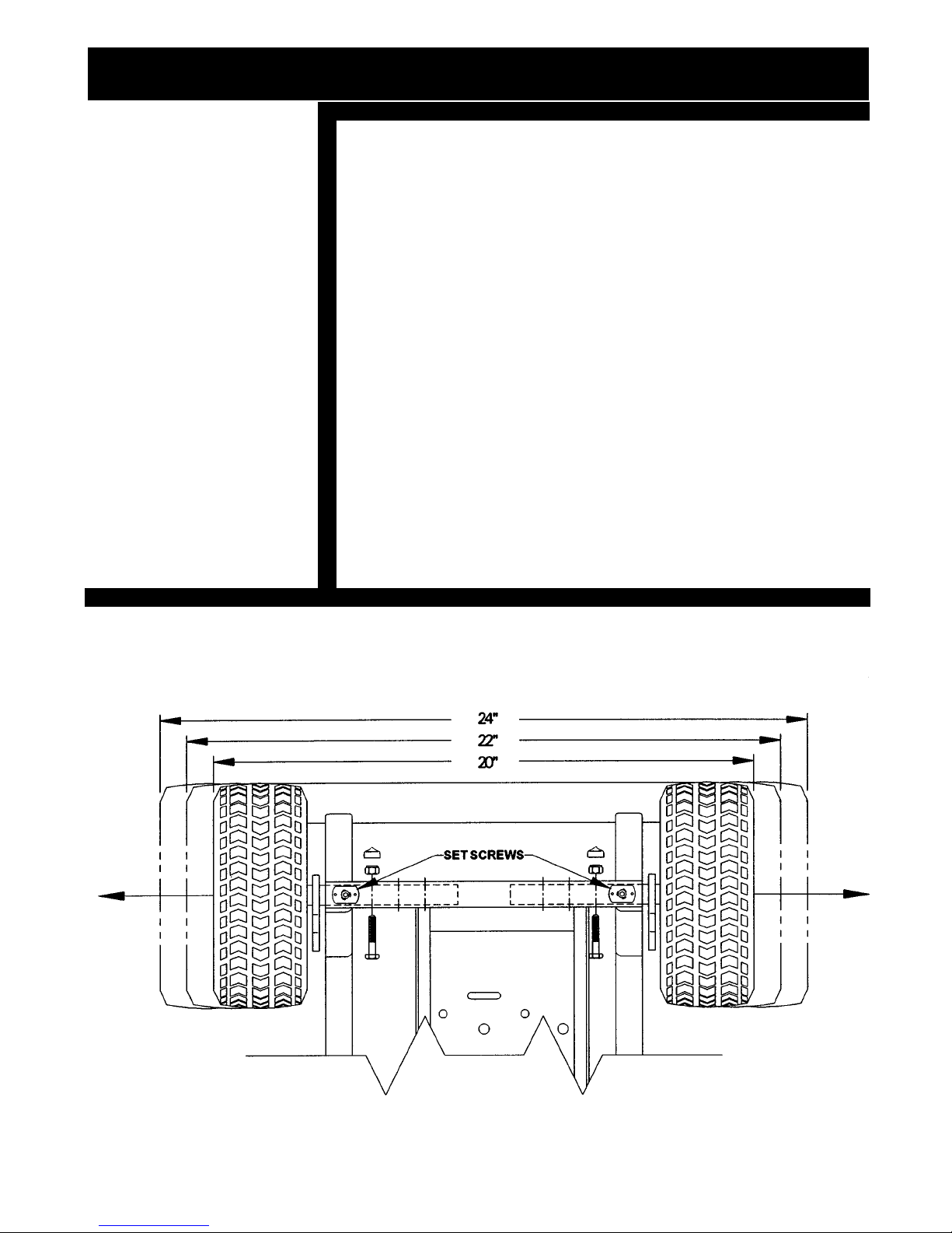
REAR WHEEL ADJUSTMENT
There are three positions for rear wheel adjustment. The
overall width of the scooter changes with each adjustment.
For the most stable outdoor use, extend the wheels to 24
inches.
TO ADJUST THE WHEELS:
15
HINT:
IF YOU FIND YOUR-
SELF ADJUSTING
WHEEL WIDTHS
OFTEN, OUR QUICK
RELEASE WHEEL
OPTION MAY
BENEFIT YOU.
REAR WHEEL ADJUSTMENT
1. Loosen the set screws located on the frame axle
tube shown on the illustration below.
2. Remove the existing bolts, locknuts and decorative
caps from the frame axle tube.
3. Slide the wheels to the desired position, making sure
the same change is done on each side. This will
ensure a safe and balanced ride.
4. Replace the bolts, tighten nuts in the frame axle
tube and tighten the set screws.
UNDERSIDE VIEW OF SCOOTER
NORMALLY SHIPPED IN EXTENDED POSITION
© 2001 BRUNO INDEPENDENT LIVING AIDS, INC.
Page 16
16
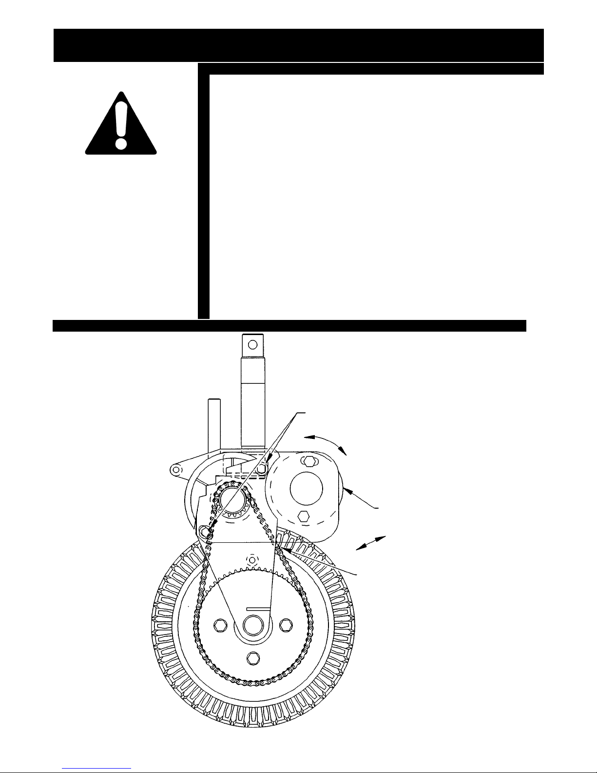
ADJUSTING CHAIN TENSION
[ ] Remove the drive side shroud (#12 on exploded view)
[ ] Loosen the two screws shown.
[ ] Grasp motor and pivot up.
CAUTION:
ALWAYS DISCONNECT
BATTERY FROM
SCOOTER BEFORE
WORKING ON IT.
HAVE CHAIN CHECKED
EVERY 6 MONTHS FOR
PROPER TENTION
ADJUSTING CHAIN TENSION
[ ] Place chain on the sprockets and lubricate with a lithium
based chain lube.
[ ] Grasp motor and pivot down so that the chain is snug. The
chain is at correct tension when it can move 1/4" side to
side.
[ ] Tighten screws.
[ ] Check chain tension again (it sometimes moves when the
screws are being tightened).
[ ] Replace drive shroud.
LOOSEN THESE SCREWS
MOTOR PIVOT
© 2001 BRUNO INDEPENDENT LIVING AIDS, INC.
MOTOR
CHAIN MOVEMENT
CHECK CHAIN TENSION
HERE
Page 17

BATTERY INFORMATION
NOTE:
IF THE SCOOTER
BATTERIES ARE LOW
ON CHARGE, THE
YELLOW LIGHT WILL
GLOW STEADILY. AS
THE BATTERIES ARE
BEING CHARGED, THE
YELLOW LIGHT WILL
BEGIN TO FLASH,
RAPIDLY AT FIRST,
THEN MORE SLOWLY
AS THE BATTERIES
ACQUIRE THEIR
CHARGE. THE GREEN
LIGHT WILL BEGIN TO
FLASH AS THE BATTER-
IES APPROACH FULL
CHARGE. THE BATTER-
IES ARE FULLY
CHARGED WHEN THE
GREEN LIGHT BLINKS
SLOWLY AND
STEADILY.
17
We recommend using only gelled electrolyte batteries
(commonly called gel cells) or starved electrolyte batteries
because it eliminates potential acid spills, reduces emission
of corrosive vapors and allows you to transport your scooter
on commercial airlines. In addition, our battery charger is
calibrated specifically for use with specific gelled electrolyte or
starved electrolyte batteries and is not suited for use with
conventional lead-acid batteries. The specific batteries we
recommend with the Cliplight charger are: Johnson Control
JC12170 and Sonnenschein A200-90555.
OPTIONAL BATTERY CHARGER PACKAGE:
The 5 AMP INTERACTER charger will allow you to use any
Gel or Starved electrolyte battery.
STANDARD BATTERY PACKAGE:
The standard battery pack is a 24 volt unit with (2)
12 volt, 17 amp-hour batteries, and has a range of 14-16
miles under normal conditions.
OPTIONAL BATTERY PACKAGES:
The extended range package contains (2) U1 batteries connected in series to create a 24 volt system. The range is
extended to 30 miles under normal conditions.
CHARGING YOUR REGAL CUB'S BATTERIES
You REGAL CUB comes equipped with an automatic 3-amp
battery charger.
To charge your batteries on the scooter:
1. Position the scooter and battery charger near a
standard electrical wall outlet.
2. Pull the Key Jack to the "off" position.
NOTE:
IF OPTIONAL 5 AMP
INTERACTER CHARGER
IS USED THE GREEN
LED WILL GLOW
CONTINUOUSLY WHEN
BATTERY IS CHARGED
(OR IN FLOAT/STANDBY
CONDITION)
3. Plug the charger into the battery charger receptacle on
the REGAL CUB is located on the left side of the Control
Module on the top of the Tiller.
CHARGER RECEPTACLE LOCATION
CHARGER RECEPTACLE
© 2001 BRUNO INDEPENDENT LIVING AIDS, INC.
Page 18

18
BATTERY INFORMATION
4. Plug the charger into the wall outlet. The red power
On indicator will light.
5. The yellow charging light on the charger will light.
6. When the batteries are fully charged, and the green
light is on, unplug the charger from the wall outlet,
and disconnect the charger from the scooter. Although
this charger will automatically shut down when the
batteries are fully charged, for safety's sake, the
charger should not be left on for a period of time
longer than is needed to fully charge the batteries.
Batteries which are in good condition can normally be recharged in approximately 6 hours.
NOTE: The optional 5 AMP INTERACTER charger can
charge any sealed, gel and starved electrolyte battery. It will
charge the standard battery pack in approximately 3-5 hours.
TO CHARGE YOUR BATTERIES OFF THE SCOOTER:
(The extended range package has separate instructions.)
1. Position the battery box and battery charger near an
electrical wall outlet.
2. Plug the charger into the mating plug on the battery
box.
3. Plug the charger into the wall outlet. The red
Power On indicator will light.
4. The yellow Charging light on the charger will
light.
NOTE:
If the scooter batteries are low on charge, the yellow light will
glow steadily. As the batteries are being charged, the yellow
light will begin to flash, rapidly at first, then more slowly as the
batteries acquire their charge. The batteries are fully charged
when the green light blinks slowly and steadily. NOTE: When
using the Interacter Charger, the green LED will glow
continuously when the batteries are fully charged.
5 AMP INTERACTER BATTERY CHARGER FUSE REPLACEMENT
If the charger is subject to a power line surge, the AC input
fuse may `BLOW' This fuse is located beneath the power
cord from the wall outlet to prevent shock hazard, to replace
fuse:
:
© 2001 BRUNO INDEPENDENT LIVING AIDS, INC.
1) Remove Power Cord from wall outlet and charger socket.
2) Pull out on the fuse access panel.
3) Remove fuse.
4) Replace with the same size and type: (BUSS # GMC 4) 5 x
20mm-4AMP/125V-TIME LAG
Page 19
BATTERY INFORMATION
CIRCUIT BREAKER
A Manual Reset Circuit Breaker (White Button) is located on
the Battery Case for easy access. This safeguard is to
protect wiring and batteries against damage in the case of a
short circuit or excessive current draw.
1. Do not attempt to prevent circuit breaker operation by
holding the button down as this may result it damage to
the REGAL CUB or personal injury.
2. If the circuit breaker should trip, your REGAL CUB will
stop and the battery display will go "out".
3. To reset the breaker, wait a few moments, then push
the white button in.
4. Do not bypass the breaker.
FOR MAXIMUM BATTERY LIFE:
19
1. Charge batteries regularly.
2.
Avoid deep discharge of the batteries whenever possible.
3. Don't let the batteries sit for long periods of time in a
state of deep or partial discharge.
4. Always replace batteries as a set, and do not mix
battery brands.
NOTE: Always disconnect the charger at the scooter after
unplugging the charger or the batteries will discharge
through the charger.
BATTERY CONNECTION
CONNECT
HARNESS TO
BATTERY HERE
© 2001 BRUNO INDEPENDENT LIVING AIDS, INC.
Page 20
20
BATTERY INFORMATION
© 2001 BRUNO INDEPENDENT LIVING AIDS, INC.
Page 21

OPERATION
21
NOTE:
AS A SAFETY
PRECAUTION, REVERSE
SPEED IS LIMITED
TO 60% OF
MAXIMUM FORWARD
SPEED.
NOTE:
FOLD TILLER BEING
CAREFUL NOT TO
DAMAGE LIGHT
SWITCHES
CAUTION:
WHEN LOWER TILLER
BOOT IS OFF BE
CAREFUL TO KEEP
FINGERS AND HANDS
AWAY FROM MOVING
PARTS
TILLER HEIGHT ADJUSTMENT
TILLER HEIGHT ADJUSTMENT
EACH TILLER HAS 2" OF HEIGHT ADJUSTMENT
[ ] Using a 5/32 Allen Wrench remove Screws, then remove
the Upper Front Cover Plate before adjusting height.
[ ] Loosen *(DO NOT REMOVE) 5/16" Bolt Head facing
seat (1/2" Nut Driver Required)
[ ] When desired height is acquired tighten Bolt Head and
replace Upper Front Cover Plate.
*WARNING: IF YOU REMOVE 5/16" BOLT, THE LOCK
PLATE INSIDE OF TILLER WILL DISASSEMBLE
REQUIRING EXTENSIVE DISASSEMBLY TO REPAIR
ANGLE ADJUSTMENT
[ ] The Tiller has a complete range of motion within 110
degree range
[ ] You can position the tiller very easily by pressing in the
release lever and moving the tiller into the desired
position. This can be done one handed or if more
leverage is required, while holding in lever, push or pull
using the Handlebars.
[ ] When release lever is not pushed in, Tiller is locked into
position.
[ ] Do not try adjusting tiller while moving.
TILLER LOCK
REMOVE
SCREWS
UPPER FRONT
COVER PLATE
LOOSEN FOR
HEIGHT
ADJUSTMENT
(DO NOT REMOVE)
PUSH TO
DISENGAGE
LOWER TILLER
BOOT
© 2001 BRUNO INDEPENDENT LIVING AIDS, INC.
Page 22

22
OPERATION
TILLER OPERATION
This tiller has an important safety feature. The harder you
push or pull on it, the tighter it locks in that direction this is
called `Posi-Lock.
IF THE TILLER IS RAISED
1) Depress lever forward and hold.
2) Push tiller forward slightly releasing lock.
3) Then pull it toward you to the desired position.
PUSH LEVER TO RAISE TILLER
1)1) Depress lever forward and hold.
2) Push tiller down slightly releasing lock.
3) Then pull tiller up to desired position.
Your tiller can be positioned into any location within a 110
degree range. This allows you to have a comfortable and
correctly positioned ride.
REMEMBER FOR SAFETY - DO NOT CHANGE THE
TILLER POSITIONING UNLESS YOU ARE STOPPED
AND THE UNIT IS `OFF.
PUSH LEVER TO FOLD TILLER
© 2001 BRUNO INDEPENDENT LIVING AIDS, INC.
Page 23

CAUTION:
BEGIN DRIVING
YOUR REGAL CUB
SLOWLY.
GRADUALLY
INCREASE SPEED
AS YOU GAIN
EXPERIENCE.
OPERATION
23
SPEED LIMITER SWITCH
With the Key removed locate the Maximum Speed Limiter
(black knob with red top) and turn it counter clockwise. When
turning the knob in this direction you have limited the speed the
scooter will travel. If the state of charge of the batteries is low
the scooter may not move at this setting when the Key is inserted and the Thumb Control Lever is depressed. It is always
best to practice driving the scooter at the minimum speed at first
and increase speed gradually as the user feels comfortable.
With the Key removed, gradually push the right side of the
Thumb Control Lever (Finger Control Lever is optional) through
its complete range of motion to get the feel of it. If the Key had
been inserted, the scooter would have accelerated forward to
the maximum speed allowed by the Maximum Speed Limiter.
With the Key removed, depress the left side of the Thumb
Control Lever through its complete range of motion. If the Key
had been inserted, the scooter would have accelerated in reverse to the maximum speed allowed by the Maximum Speed
Limiter.
TILLER CONTROLS
ADJUSTING MAXIMUM SPEED LIMITER
KEY
SPEED
LIMITER
HORN
© 2001 BRUNO INDEPENDENT LIVING AIDS, INC.
Page 24

24
CAUTION:
ALWAYS USE YOUR
MANUAL PARKING
BRAKE WHEN BOARD-
ING OR EXITING YOUR
SCOOTER.
OPERATION
BOARDING YOUR SCOOTER
Position the scooter for easy transfer. Engage the manual
rear wheel parking brake. Depress red lever on tiller and
hold. Push tiller forward slightly releasing lock. Rotate the
seat 90 degrees using swivel lever (see page 9 for lever
positioning) flip arm up for easy entry. After the rider is
securely in place, rotate the seat, flip down the arm rest.
Depress lever on tiller forward and hold. Pull tiller up to
desired position and release lever.
BRAKING
To stop the REGAL CUB, simply release the Finger Control and the REGAL CUB will stop gently.
When descending a hill with the Thumb Control depressed,
the REGAL CUB'S regenerative braking circuit will control
the speed of the scooter. When the Finger Control is
released, the Dynamic brake will gently stop the scooter.
The Manual Rear Wheel Brake prevents the REGAL CUB
from rolling on an incline.
MANUAL REAR WHEEL BRAKE
ON
OFF
© 2001 BRUNO INDEPENDENT LIVING AIDS, INC.
Page 25

OPERATION
BATTERY CONDITION
When you Push in Key Jack to the on position, the Battery
Condition Indicator's lights will all light up when the batteries are fully charged. If the batteries are half charged the
two left lights will light up. If the batteries are very low, only
the left indicator will light up. When the left indicator light is
the only one on, the batteries should be charged before
attempting to drive the scooter over a long distance. REVIEW THE BATTERY INFORMATION SECTION OF THIS
MANUAL FOR CHARGING INSTRUCTIONS.
BATTERY CONDITION INDICATOR'S LIGHTS
INDICATOR LIGHTS
25
NOTE:
WHEN FILLING
TIRES WITH AIR A
DOUBLE HEADED
AIR CHUCK WORKS
THE BEST.
(AVAILABLE IN
MOST
AUTOMOTIVE
STORES OR
AUTOMOTIVE
DEPARTMENTS)
PRACTICE
Practice driving your REGAL CUB in an unobstructed open
area until you are familiar with the controls and feel comfortable and in control of the scooter.
CAUTION: BEGIN DRIVING YOUR REGAL CUB SLOWLY
BY SLIGHTLY DEPRESSING THE FORWARD LEVER.
GRADUALLY INCREASE SPEED AS YOU GAIN EXPERIENCE. WITH A LITTLE PRACTICE, DRIVING THE REGAL
CUB WILL SEEM NATURAL AND EASY. REVIEW THE
SAFETY SECTION OF THIS MANUAL.
FILLING TIRES (TYRES) WITH AIR
Remove the Hub Cap before filling the tires with air.
AIR CHUCK
FILL TIRES TO SPECIFIED PSI
PRINTED ON EACH TIRE
DOUBLE ENDED
AIR CHUCK
IF FOAM FILLED TIRES SIT
FOR A LONG PERIOD OF
TIME THEY WILL DEVEL-
OPE FLAT SPOTS. THESE
FLAT SPOTS WILL "ROLL"
OUT WHEN THE UNIT
MOVES AFTER 20 OR SO
NOTE:
REVOLUTIONS.
© 2001 BRUNO INDEPENDENT LIVING AIDS, INC.
Page 26

26
MAXIMUM RECOMMENDED INCLINE
MAXIMUM RECOMMENDED INCLINE
Bruno Independent Living Aids, Inc. has performed extensive
incline testing on its scooters and powerbases. Your scooter
has a maximum rated angle that is listed on the specification
page. This is based on the Maximum rated load in a standard
seat position (seat back upright and seat bottom in middle
adjustment)
Your scooter seat can be positioned through a wide range of
adjustments and have numerous accessories mounted that
effect the balance point of the unit. After the seat is adjusted
and the accessories are positioned the actual maximum safe
slope will have to be determined. In a Rear Wheel Drive (RWD)
Scooter this is the angle that the front wheel(s) start to lift off
the ground. This can be measured with the rider and
accessories on the unit using an inclinometer.
Your Front Wheel Drive (FWD) Scooter can usually safely
climb and 8 or 9 degree slope, steeper than 9 degrees the unit
loses traction on the drive wheel and the unit will not continue
to climb.
SCOOTER INCLINE
© 2001 BRUNO INDEPENDENT LIVING AIDS, INC.
Page 27

MANUAL REAR WHEEL BRAKE
REVERSING THE BRAKE
The manual rear brake can be installed on either the right or
left side. By removing the four hex head cap screws the
brake can be reinstalled on the opposite side using the
illustration below. Remember to flip the cam follower
bracket.
CAUTION:
Before tightening down the brake, push the brake lever in
ALWAYS USE YOUR
MANUAL PARKING
BRAKE WHEN
BOARDING OR
EXITING YOUR
SCOOTER.
MANUAL BRAKE LOCATION
the off position. The brake must be rotated so the clearance between the tire and the cam follower is approximately
1/4". Try the brake in the on position approximately 14".
Try the brake in the on position and off position several
times until the brake is adjusted properly. When the positioning is correct tighten all bolts securely.
27
CAM FOLLOWER BRACKET
© 2001 BRUNO INDEPENDENT LIVING AIDS, INC.
Page 28

28
TRANSPORTING YOUR REGAL CUB
MOVING YOUR REGAL CUB MANUALLY
If your REGAL CUB must be moved manually make sure the
hand brake is released and the key switch is off. DO NOT
RIDE OR SIT ON THE SCOOTER WHEN IT IS BEING
PUSHED OR PULLED.
TRANSPORTING YOUR REGAL CUB BY CAR OR VAN
By folding the tiller down and removing the seat, your REGAL CUB can be placed in most trunks or vans. First re-
move the seat by simply lifting the seat straight up. Depress
red lever forward and fold tiller down.
By using one of BRUNO's wide selection of Scooter Lifts, the
REGAL CUB can be lifted into many car trunks (the seat
must be removed) and into most vans and mini-vans with no
disassembly.
TRANSPORTING YOUR REGAL CUB BY PLANE
Your REGAL CUB can be transported on most commercial
airlines. The scooter can usually be driven directly to the
gate and checked in at that time. Gel Cell and starved
electrolyte batteries can be transported on the plane. It is
best to make arrangements for transporting the REGAL CUB
with the individual airline when making reservations.
IF YOU DO NOT USE GEL CELL OR STARVED
ELECTROLYTE TYPE BATTERIES, YOU CANNOT
TRANSPORT THE BATTERIES BY PLANE OR TRAIN.
© 2001 BRUNO INDEPENDENT LIVING AIDS, INC.
Page 29

SWITCHING THUMB CONTROL DIRECTION
29
[ ] Turn unit OFF - removing Key Jack.
[ ] Remove all four #10 screws holding the two tiller plastic
pieces in place.
[ ] Tilt the Tiller Top forward.
[ ] Flip switch from R (Right Hand Forward to L (Left Hand
Forward).
[ ] Close plastic and replace screws.
[ ] Pull Thumb Control Covers off, and flip around. This makes
sure the Icon is facing the correct direction!
[ ] Test unit left hand forward. Should be almost twice as fast as
right hand reverse.
REMOVE TILLER SHROUD
REMOVE FOUR
PHILLIPS
SCREWS
(TWO ON EACH
SIDE)
[ ] Instruct the customer.
© 2001 BRUNO INDEPENDENT LIVING AIDS, INC.
Page 30

30
[ ] Have a qualified service technician clean, check, and lubricate the unit at least once
a year.
[ ] Check tires (pressure, wear, patterns). (Note: If foam filled tires sit for a long period
of time they will develope flat spots. These flat spots will "roll" out when the unit
moves after 20 or more revolutions.
[ ] Check Batteries (load test).
[ ] Check battery charger, plug in and check.
voltage @ batteries (28.8 VDC for 24 VDC)
[ ] Check seat swivel lock.
[ ] Examine Throttle control, is it centered and does it spring back correctly?
[ ] Make sure key switch is `tight.
SCOOTER MAINTENANCE
[ ] Is Maximum Speed Pot allowing for full range of speeds?
[ ] Check Head Set for smooth swiveling, correctly tightened or, feel for grit or other
foreign material, clean and re-grease.
[ ] Check that brake works correctly.
[ ] Examine the belt (on Regal and FWD Cub) for wear and correct tension (twist test).
[ ] Check Bearings on differential.
[ ] Check Chain on FWD Cub, clean, grease, adjust tension, replace if worn.
[ ] Check wheel bearings.
[ ] Check Parking brake on FWD Cub, adjust if necessary.
[ ] Check Quick Release Pins (if applicable).
[ ] Check all bolts to make sure their tightened properly.
© 2001 BRUNO INDEPENDENT LIVING AIDS, INC.
Page 31

AVAILABLE OPTIONS
*NOTE:
IF FOAM FILLED
TIRES SIT FOR A
LONG PERIOD OF
TIME THEY WILL
DEVELOPE FLAT
SPOTS. THESE
FLAT SPOTS WILL
"ROLL" OUT WHEN
THE UNIT MOVES
AFTER 20 OR SO
REVOLUTIONS.
31
OPTION LIST
1. FRONT BASKET
3. BATTERIES, U-1 GEL CELL
4. BATTERY CHARGER, OPTIONAL INTERACTER 5 AMP
5. CANE HOLDER, FISH-ON SEATS (REQUIRES
RECEIVER TUBE PARTS KIT).
6. CANE HOLDER w/HEADREST (REQUIRES RECEIVER
TUBE PARTS KIT)
7. CANE HOLDER, STRAIGHT (DELUXE & PREMIUM
SEATS ONLY)
8. CRUTCH HOLDER, (REQUIRES RECEIVER TUBE
PARTS KIT).
9. CRUTCH HOLDER w/HEADREST (REQUIRES
RECEIVER TUBE PARTS KIT).
10. HEADREST, ADJUSTABLE (REQUIRES RECEIVER
TUBE PARTS KIT)
11. LONG RANGE PACKAGE, (BATTERIES NOT
INCLUDED)
12. OXYGEN CYLINDER HOLDER - SEAT BOTTOM
MOUNT
13. OXYGEN CYLINDER HOLDER - RECEIVER TUBE
MOUNT (REQUIRES RECEIVER TUBE PARTS KIT)
14. *PUNCTURE RESISTANT TIRES w/SEALANT
15. QUICK RELEASE PIN FOR INNER SEATPOST
QUICK RELEASE PIN
16. QUICK RELEASE PINS FOR REAR WHEEL WIDTH
17. REAR FENDERS (REQUIRED WHEN ORDERED WITH
COLORED SHROUDS
18. RECEIVER TUBE PARTS KIT, CUB DELUXE SEAT
19. RECEIVER TUBE PARTS KIT, FISH-ON SEAT
20. RECEIVER TUBE PARTS KIT, PREMIUM SEAT w/
FLIP-UP ALUMINUM UPHOLSTERED ARMRESTS
© 2001 BRUNO INDEPENDENT LIVING AIDS, INC.
Page 32

32
AVAILABLE OPTIONS
OPTION LIST
21. RECEIVER TUBE PARTS KIT, PREMIUM SEAT
w/FLIP-UP REMOVABLE ARMRESTS
22. SEAT BELT, NON-RETRACTABLE
23. SEAT BELT, RETRACTABLE
24. THUMB LEVER CONTROL w/BLACK ACCENT
GRIPS
25. THUMB LEVER CONTROL w/RED ACCENT GRIPS
26. SWIVEL PLATE, ALLOWS LOCKING IN 360
DEGREES
27. WALKER HOLDER - SEAT BACK MOUNT (DELUXE
& PREMIUM SEATS)
28. WALKER HOLDER - RECEIVER TUBE MOUNT
(REQUIRES RECEIVER TUBE PARTS KIT)
29. REAR TRAILER
30. ELEVATING POWER SEAT, TOGGLE SWITCH
CONTROL OR SEAT PENDANT CONTROL
31. FRONT BUMPER
FRONT BUMPER
RECEIVER TUBE INSTALLATION
[ ] The Receiver Tube
must be mounted to
the rear of the seat
with the hardware
provided. Insert option
into the receiver tube
and secure by
tightening black knob.
© 2001 BRUNO INDEPENDENT LIVING AIDS, INC.
TOOLS NECESSARY FOR INSTALLATION
[ ] (2) 1/2" COMBINATION WRENCHES
Page 33

AUXILIARY PLATFORM ASSEMBLY
33
© 2001 BRUNO INDEPENDENT LIVING AIDS, INC.
Page 34

34
TRAILER OPTION
© 2001 BRUNO INDEPENDENT LIVING AIDS, INC.
Page 35

WALKER HOLDER OPTION
35
*NOTE:
ON THE CUB
DELUXE SEAT THE
BACK SEAT
PADDING NEEDS TO
BE PEELED BACK TO
EXPOSE THE
BRACKETS.
INSTALLATION INSTRUCTIONS FOR REGAL PREMIUM / CUB DELUXE
[ ] Remove the phillips round head machine screws on the
upper half of the seat hinge (three on the Regal
premium seat, and two on the *Cub deluxe seat). Place
the Mounting Bracket over the seat hinge, aligning with
existing holes and replace the screws securely.
MOUNTING WALKER HOLDER ON PREMIUM SEAT
ADJUSTING THE HEIGHT
[ ] The height of the Holder Bracket is adjustable. If the
desired height is at the lowest position the set screw is
to be at the upper most hole to act as a safety stop.
The thread cutting screw can be moved to the position
desired. When the desired position is achieved the
knob on the Slide Tube Weldment should be tightened.
MOUNTING BRACKET ON A 17" SEAT
[ ] Install Mounting Bracket as shown with a 15" Premium
Seat and a Deluxe Seat. Note: When installing a 17"
Premium Seat the Mounting Bracket must be flipped so
the flange is closer to the center of the seat
(SEE ILLUSTRATION ABOVE).
© 2001 BRUNO INDEPENDENT LIVING AIDS, INC.
Page 36

36
NOTE:
THIS CANE HOLDER
ALSO FITS ON THE
DELUXE CUB SEAT
USING THE EXISTING
HOLES IN THE SEAT
BACK. TO EXPOSE
THE FRAME ON THE
BACK OF THE
DELUXE SEAT, FOLD
OVER THE LOWER
CORNER
FLAP ON THE BACK
OF THE SEAT.
CANE HOLDER
CANE HOLDER OPTION
Secure the Cane Holder using the existing hardware on the
Premium Seat as shown below.
CANE HOLDER SHOWN ON A PREMIUM SEAT
When installing a Cane Holder on a Fish On Seat align the
Cane Holder on the back of the chair as shown below it may be
mounted either on the right side or the left side. Mark the top
and bottom hole locations. Remove the seat padding and drill
(2) 17/16" holes to accommodate (2)1/4-20 x .75 Hex Head Cap
Screws, (2) 5/16 Fender Washers, (2) .563 OD X .268 ID X .048
Washers Black Zinc, and (2) 1/4" Hex Head Dome Fastener
Covers shown below. Holes will have to be made in fabric on
Seat Back for hardware.
CANE HOLDER SHOWN ON A FISH-ON SEAT
© 2001 BRUNO INDEPENDENT LIVING AIDS, INC.
Page 37

SEAT BACK ANGLE ADJUSTMENT
37
© 2001 BRUNO INDEPENDENT LIVING AIDS, INC.
Page 38

38
POSITIONING BELT (OPTION)
FISH-ON SEAT
PREMIUM SEAT
© 2001 BRUNO INDEPENDENT LIVING AIDS, INC.
Page 39

RETRACTABLE LAP BELT
39
© 2001 BRUNO INDEPENDENT LIVING AIDS, INC.
Page 40

40
CRUTCH HOLDER
CRUTCH HOLDER INSTALLATION INSTRUCTIONS
[ ] The Receiver Tube must be
mounted to the rear of the seat
with the hardware provided.
Insert option into the receiver
tube and secure by tightening
black knob.
[ ] Slide the crutch holder into the
receiver tube. Tighten knob to
secure. Install Holder bracket
at desired height. When the
crutch holder is in place tighten
knobs.
[ ] Hang the crutches on the Holder
Brackets. Check height of
Holder Brackets before using.
WALKER HOLDER (FISH ON SEAT)
SLIDE WALKER HOLDER INTO THE RECEIVER TUBE
INSTALLATION
CARRYING POSITION
[ ] Slide the walker holder into the
receiver tube. Tighten knob to
secure. Install Holder bracket at
desired height. When the walker
holder is in place & tighten
knobs.
[ ] Hang the folded walker on the
Holder Brackets as shown.
Check height of Holder Brackets
before using.
CHECK WITH YOUR AUTHORIZED BRUNO DEALER FOR ACCESSORY PRICES AND AVAILABILITY
© 2001 BRUNO INDEPENDENT LIVING AIDS, INC.
Page 41

SCHEMATIC DIAGRAM
41
© 2001 BRUNO INDEPENDENT LIVING AIDS, INC.
Page 42

42
EMI AND RFI INFORMATION
October 14, 1999
Dear Customer,
We want to take a few minutes and explain the information that is coming into the market on
Wheelchairs and Scooters relating to EMI / RFI. Over the next several months you are going to
be seeing a lot of press on RFI / EMI.
First, what is EMI and RFI? EMI is Electro Magnetic Interference. RFI is Radio Frequency
Interference. This is energy that you cannot see, and it is very hard to detect its intensity levels.
All electronic devices that have transformers or switch electrical power, such as television and
radio transmission antennas, welders, cellular phones, motors, 2 way radios etc... produce one
or the other in some amount. The vast majority of these devices are properly shielded so that
they do not leak much of this energy outside of their cases, thus having little effect on products
around them. EMI and RFI have been around since electricity was harnessed, they are not new
phenomenon.
The U.S. Food And Drug Association recently has been making public, concerns they have
over how durable medical equipment reacts when in contact with devices that give off higher
levels of EMI / RFI. This started about 2 years ago when they discovered some hospital equipment operating erratically when people nearby used cellular phones. With the popularity of
Cellular and 2-way communication blossoming, the FDA's concern level has risen.
As of December 2nd, 1994 all new wheelchairs and scooters should have instructional warning
tags and we are requested to educate the public on the effects of EMI and RFI. Only you can
take off the informational tag hanging from the tiller. A scooter or wheelchair without the tag will
be considered mislabeled. This is our way of hoping you at least get to read the basics about
EMI/RFI.
The best education is to be aware of the area around you and know how your wheelchair or
scooter normally operates. If you sense that the unit is operating erratically, turn it off. If the unit
is off, it can not be influenced by EMI or RFI. When in doubt, turn the key OFF. Report any
erratic behavior to your dealer and to the manufacturer as soon as possible. Is your scooter
safe? YES, but like all appliances, you must follow basic common sense guidelines to operate it
safely.
If you use a cellular phone or a 2-way radio, turn the scooter or wheelchair off before using it.
The accompanying chart was developed based on FDA guideline information of the worst
possible situations regarding wheelchair and transmission sources. Adhering to these suggested distances should dramatically reduce the possibility of EMI / RFI interference.
The Regal and Cub line of scooters use mechanical steering, extensive design and testing
reviews along with quality components to minimize the EMI / RFI interference possibilities.
If you have any questions, please feel free to contact us at 1-800-882-8183. This line has an
answering machine for non business hours and some one will contact you as soon as possible.
© 2001 BRUNO INDEPENDENT LIVING AIDS, INC.
Page 43

FDA EXPLANATION OF DISTANCE CHART
Explanation of Separation Distance Table
To find the minimum recommended separation distance between a medical device and a
transmitter from this table, first locate the value in the top row that is closest to the RF immunity of the medical device. Then follow that column down to the row corresponding to the
rated power of the transmitter. The entry in that cell of the table is the minimum recommended separation distance between that medical device and that transmitter.
The recommended separation distance is approximate. The separation distances were
calculated using the following equation:
43
d = 18.04
Where P is the peak power of the transmitter in watts (W), E is the immunity of the medical
device in volts per meter (V/m), and d is the recommended separation distance in feet. This
approximation becomes very inaccurate at distances less than the wavelength of the transmitter. Therefore, for low-power sources that are normally hand-held, the minimum recommended separation distance is one foot.
The actual separation distance is affected by antenna efficiency and pattern; multipath reflections; and absorption of buildings, objects, and people. Multipath reflections could increase
the actual separation distance, and absorption could decrease it.
Each recommended separation distance was calculated assuming a single transmitter. If
multiple sources (e.g. cellular phones) are in use, the actual separation distance should be
increased.
Each recommended separation distance was calculated assuming that the transmitter is
transmitting at the maximum power allowed by the FCC for that type of transmitter. In fact,
the actual transmitted power could be less than the maximum, in which case the separation
distance could be decreased.
P
E
Also, each recommended separation distance was calculated assuming that the worst-case
susceptibility of the medical device occurs at the frequency of the particular transmitter of
interest. This may not be the case; if not, the actual separation distance could be decreased.
© 2001 BRUNO INDEPENDENT LIVING AIDS, INC.
Page 44

44
RECOMMENDED EMI SEPARATION DISTANCE
Immunity Level of
Medical Device
Peak Power Rating
of Radio Source and
Example Sources
Unknown
(assume
0.1 V/m)
1 V/m
3 V/m
10 V/m
20 V/m
40 V/m
7 mW
Microcell Cellular
Phone
10 mW
100 mW
Wireless Computer
Equipment
600 mW
Portable Cellular
Phone
1W
2 W
Transportable Cellular
Phone
5 W
10 W
15'
18'
57'
140'
180'
224'
403'
571'
1.5'
2'
6'
14'
18'
22'
40'
57'
1'
1'
2'
5'
6'
7'
13'
19'
1'
1'
1'
1.4'
2'
2'
4'
6'
1'
1'
1'
1'
1'
1.1'
2'
3'
1'
1'
1'
1'
1'
1'
1'
1.4'
20 W
50 W
100 W
State Police Radio
Amateur Radio
1500 kW
Amateur Radio
100 kW
FM Broadcast
TV Stations 2-6
316 kW
TV Stations 7-13
5 MW
TV Stations 14-69
© 2001 BRUNO INDEPENDENT LIVING AIDS, INC.
0.2 mile
0.3 mile
1.3 miles
10.8 miles
19 miles
76 miles
807'
81'
128'
180'
699'
1.1 miles
1.9 miles
7.6 miles
27'
43'
60'
233'
0.4 mile
0.6 mile
2.5 miles
8'
13'
18'
70'
571'
0.2 mile
0.8 mile
4'
6'
9'
35'
285'
507'
0.4 mile
2.0'
3.2'
4.5'
17'
143'
254'
0.2 mile
Page 45

TROUBLESHOOTING
45
SYMPTOM
IS UNIT NOT
RUNNING?
IS UNIT NOT
RUNNING?
IS UNIT NOT
RUNNING?
DOES UNIT RUN SLOW,
OR WEAK?
COMMENTS
n BATTERY GAGE ON
n BATTERY GAGE ON,
n RELAY CLICKS
n KEY JACK IS IN ON
POSITION, NO F/R
RELAY CLICK
n BATTERY GAGE
OFF NO RELAY
CLICK
n BATTERY GAGE
FLASHES LED
BARS CYCLING
UP & DOWN
PROBABLE CAUSE
n SAFETY SWITCH ON BRAKE
n SPEED LIMITER SET TOO LOW
n MOTOR CONNECTION (CHECK
FOR BRAKE CLICK)
n CONTROL POT DISCONNECTED
(OPEN LEADWIRE)
n CIRCUIT BREAKER (CHECK BOTH)
n BATTERY CABLE CONNECTION
(CHECK BOTH)
n CHECK CONTROL CABLE
CONNECTION
n LOW BATTERIES
n POOR CONNECTION IN BATTERY
CABLES (RUN SEVERAL
MINUTES, FEEL CONNECTORS
FOR WARM OR HOT
CONNECTIONS)
n MOTOR DEFECTIVE (SHORT
WINDING)
n BRAKE DEFECTIVE--CHECK
ARMATURE MOVEMENT, OPEN
COIL
DOES UNIT RUN SLOW,
OR "WEAK"?
DOES UNIT CREEP
IN NEUTRAL?
DOES BATTERY
GAGE READ LOW
OR OFF?
DOES BATTERY
CHARGER INDICATOR
STAY GREEN?
DOES UNIT RUN
WITHOUT PRESSING
THUMB CONTROL?
n BATTERY GAGE FULL
n THUMB CONTROL
FEELS OK, CENTERS
n BATTERY CHARGER
INDICATES FULL
CHARGE
n BATTERY HOT OR
SMELLS OF ROTTEN
EGGS
n THUMB CONTROL
FEELS OK
n SPEED LIMITER SET TOO LOW
n POOR MOTOR CONNECTION
n MOTOR DEFECTIVE (OPEN
WINDING)
n CONTROL POT NEEDS
CALIBRATION
n BATTERY GAGE DEFEC
TIVE OR OUT OF
CALIBRATION
n HOT BATTERY
(DEFECTIVE) RECOMMEND
REPLACING IN PAIRS
n CONTROL POT
LEADWIRES SHORTED
n POWER CONTROL
BOARD DEFECTIVE
© 2001 BRUNO INDEPENDENT LIVING AIDS, INC.
Page 46

46
TROUBLESHOOTING
SYMPTOM
DOES UNIT RUN ONLY
FORWARD OR REVERSE?
DOES UNIT RUN ONLY
FORWARD OR REVERSE?
UNIT CANNOT BE
TURNED OFF?
IS THERE A
CLUNKING NOISE
IN FRONT WHEEL?
DOES UNIT RUN
FORWARD
SLOWLY, BUT NOT
IN REVERSE?
DOES UNIT HAVE
LOUD GRINDING
NOISE?
COMMENTS
n THUMB CONTROLS
FEEL OK (1) RELAY
"CLICKS"
n (2) RELAYS CLICK
n RUNS NORMALLY
n WHEN SLOWING IN
FOWARD OR
ACCELERATING IN
REVERSE
n BATTERY GAGE
FULL
n WHEN
ACCELERATING
OR DECELERATING
n ALL CONDITIONS
PROBABLE CAUSE
n CONTROL POT
LEADWIRE OPEN
n POWER CONTROL
BOARD DEFECTIVE
n KEY SWITCH DEFECTIVE
n LOOSE HEAD SET
BEARINGS
n SPEED LIMITER SET TOO
LOW
n POOR MOTOR CONNECTION
n MOTOR DEFECTIVE (OPEN
WINDING)
n INTERNAL IN TRANSAXLE
(CALL DEALER)
n MOTOR MAGNETS LOOSE
(RARE)
IS THE UNIT IS
WET?
IS UNIT NOT
RUNNING?
DOES HEAD LIGHT
AND RUNNING
LIGHTS NOT WORK?
FUSE NOTE: The fuse specified for the BCI PC Board (PCB 00040) is a Buss GMA-10A (5 X
20 mm 10A fact acting). The alternate vendor is Little fuse P/N 216010. Bruno P/N FUS-
10002.
For the Lighting PC Board (PCB-00041) it is a Buss GMA-3.15A (5 X 20 mm 3.15A fast act-
ing). The alternate vendor is Littlefuse P/N 2163.15.
Both fuses are available from Electrical or Industrial suppliers. A list of nationwide distributors
follows.
DISTRIBUTOR TELEPHONE #
W.W. Grainger Check Phone Book for local listing (W.W Grainger does not have a 800 number)
n DOES NOT RUN, OR
RUNS ERRATICALLY
n FUSE IS BLOWN.
n BATTERY IS DEAD
n CHECK LIGHT BULB(S)
n FUSE IS BLOWN.
n TILLER CONTROL BOARDS
WET. DRY OUT UNIT, HAVE
DEALER INSPECT (DO NOT RIDE)
n REPLACE FUSE IN CONTROL
MODULE (5 X 20mm10A)
n CHARGE SCOOTER
n REPLACE BURNT OUT BULB
n REPLACE FUSE IN CONTROL
MODULE ( 5 X 20 mm 3.15A)
Newark Electronics 1-800-463-9275
Allied Electronics 1-800-433-5700
© 2001 BRUNO INDEPENDENT LIVING AIDS, INC.
Canada: 905-812-8949
Page 47

LOWER TILLER ASSEMBLY
47
© 2001 BRUNO INDEPENDENT LIVING AIDS, INC.
Page 48

48
UPPER TILLER ASSEMBLY
© 2001 BRUNO INDEPENDENT LIVING AIDS, INC.
Page 49

COMPLETE TILLER ASSEMBLY
49
© 2001 BRUNO INDEPENDENT LIVING AIDS, INC.
Page 50

50
UPPER DELTA TILLER ASSEMBLY
© 2001 BRUNO INDEPENDENT LIVING AIDS, INC.
Page 51

COMPLETE DELTA TILLER ASSEMBLY
51
© 2001 BRUNO INDEPENDENT LIVING AIDS, INC.
Page 52

52
EXPLODED VIEW
THE REAR AXIAL IS NORMALLY SHIPPED IN EXTENDED POSITION
© 2001 BRUNO INDEPENDENT LIVING AIDS, INC.
Page 53

EXPLODED VIEW
53
© 2001 BRUNO INDEPENDENT LIVING AIDS, INC.
Page 54

54
17" / 20" / 22" UPHOLSTERED ARMREST ASSEMBLIES
© 2001 BRUNO INDEPENDENT LIVING AIDS, INC.
Page 55

LEFT & RIGHT SEAT HINGE ASSEMBLY
55
© 2001 BRUNO INDEPENDENT LIVING AIDS, INC.
Page 56

56
SEAT OPTIONS
SPECIFY COLOR WHEN ORDERING PARTS
© 2001 BRUNO INDEPENDENT LIVING AIDS, INC.
Page 57

SEAT OPTIONS
SPECIFY COLOR WHEN ORDERING PARTS
57
© 2001 BRUNO INDEPENDENT LIVING AIDS, INC.
Page 58

58
EXPLODED VIEW
© 2001 BRUNO INDEPENDENT LIVING AIDS, INC.
Page 59

EXPLODED VIEW
59
© 2001 BRUNO INDEPENDENT LIVING AIDS, INC.
Page 60

60
LIMITED WARRANTY
ONE YEAR LIMITED WARRANTY
for
Bruno Scooters
Bruno Independent Living Aids, Inc. (Bruno), warrants to the original purchaser of a Bruno
CUB or SUPERCUB scooter that the Bruno CUB or SUPERCUB scooter is free from
defects in material and workmanship for a period of one year from date of purchase.
The exclusive remedy for a defect in a Bruno CUB or SUPERCUB scooter shall be the
repair or replacement, at the option of Bruno, of the defective part or component. After the
first 30 days of this warranty, only parts and components are covered. This warranty does
not cover labor and other services after the initial 30 days. If repair or replacement of a
Bruno CUB or SUPERCUB scooter is not commercially practical or cannot be timely made,
Bruno may elect to refund the purchase price of the Bruno CUB or SUPERCUB scooter
instead of repairing or replacing the Bruno CUB or SUPERCUB scooter.
IN NO EVENT SHALL BRUNO BE RESPONSIBLE FOR INDIRECT, INCIDENTAL OR
CONSEQUENTIAL DAMAGES, WHETHER SUCH DAMAGES ARISE FROM CLAIMS
BASED ON CONTRACT, WARRANTY, TORT (INCLUDING NEGLIGENCE), STRICT
LIABILITY OR PRODUCT LIABILITY. Some states do not allow the exclusion or limitation
of incidental or consequential damages, so the above limitation or exclusion may not apply
to you.
ALL IMPLIED WARRANTIES, INCLUDING ANY WARRANTY OF MERCHANTABILITY
OR FITNESS FOR A PARTICULAR PURPOSE, ARE LIMITED IN THEIR DURATION TO
THE LENGTH OF THE WARRANTY STATED ABOVE FOR THE AFFECTED
COMPONENT. Some states do not allow limitations on how long an implied warranty lasts
so the above limitation may not apply to you.
To obtain warranty service, you must follow these procedures:
1. Obtain return authorization by calling your local Bruno dealer or Bruno at
1-800-882-8768;
2. Return the Bruno CUB or SUPERCUB scooter, freight prepaid, to the address
provided by your Bruno dealer or Bruno with proof of purchase indicating the
date purchased.
Bruno will pay for shipping back to the purchaser within the continental United States
and Canada if a defect in material or workmanship is discovered. Return freight and repair
charges will be the responsibility of the purchaser if the problem is not covered by warranty.
This warranty does not cover damage or failure caused by misuse, abuse, accidents,
physical damage, modifications not made by Bruno, damage in shipment, or repairs undertaken by anyone other than Bruno factory employees or authorized distributors. The
original purchaser of a Bruno CUB or SUPERCUB scooter that is leased or rented shall
be the person or entity acting as the lessee or rental provider.
This warranty gives you specific legal rights, and you may also have other rights
which vary from state to state. Bruno specifically does not authorize any person to extend
the time or scope of this warranty.
For further information regarding this limited warranty, please contact Bruno by
calling 1-800-882-8768 or writing to Bruno at the following address:
Bruno Independent Living Aids, Inc.
Attention: Service Department
Post Office Box 84
Oconomowoc, WI 53066
© 2001 BRUNO INDEPENDENT LIVING AIDS, INC.
© 2000 BRUNO INDEPENDENT LIVING AIDS, INC.
Page 61

61
© 2001 BRUNO INDEPENDENT LIVING AIDS, INC.
Page 62

TM
THE REGAL CUB 35 3 WHEEL FWD
*ILLUSTRATION SHOWS REGAL CUB WITH
DELUXE SEAT AND FRONT BUMPER OPTIONS
BRUNO MOBILITY
Coventry Road
Lutterworth, Leicestershire LE174JB
Tel: (01455) 554242
0800 416 855
Fax: (01455) 554243
OPERATORS MANUAL
MAN-CUB-3UK
REVISED 01-02-2001
Page 63

Bruno Mobility Warranty
Your Bruno product is guaranteed for 12 months from the date of purchase against faults arising
due to defects in manufacture or materials. This guarantee does not detract from, but is in
addition to your legal rights.
Parts replaced or repaired under the terms of this guarantee will be covered for the balance of
the 12 month period.
This guarantee applies only to parts supplied or approved on behalf of Bruno Mobility. This
guarantee is not transferable.
Exclusions:- This guarantee does not extend to those items which may need replacement due
to normal wear and tear (tyres, tubes, punctures, belts, bulbs, upholstery, motor brushes, fuses,
batteries etc.), or to damage to the product caused by misuse or accident, for which Bruno
Mobility, or its agent, cannot be held responsible.
Batteries:- Batteries carry a limited guarantee from the original manufacturer, which is subject
to a stringent wear and tear clause. Any battery faults due to a defect in the original manufacture
will normally become obvious within the first two months of use.
Bruno Mobility disclaims all responsibility for any personal injury or property damage which may
occur as a result of improper or unsafe use of its products. Mechanical or electrical defects will
be dealt with on a contingency liability basis. The part or parts will be repaired, but no
responsibility for damage or injury can be implied to Bruno Mobility.
Your Bruno product must be serviced at least every 12 months or more frequently if conditions
and use require it. Please contact your authorized Bruno distributor who will be able to advise
you of their current costs affecting service visits.
Bruno Mobility, Coventry Road, Lutterworth, Leicestershire LE17 4JB, England
Telephone: (01455) 554242 or 0800 416 855 Facsimile: (01455) 554243
Page 64

 Loading...