

Bruno SRE-2700, ELECTRA-RIDE LT SRE-2700 Installation Manual
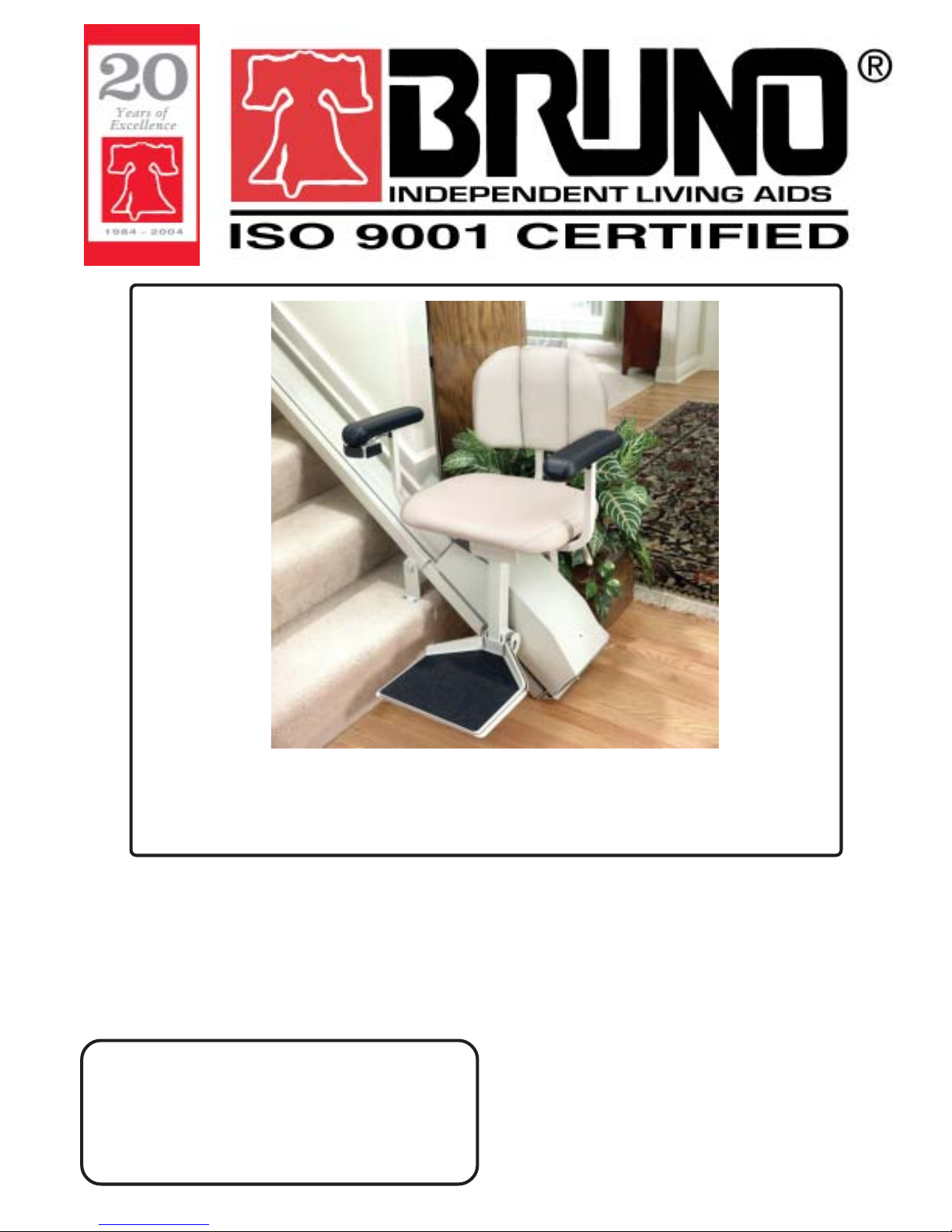
SRE-2700
ELECTRA-RIDE™ LT
STAIRWAY ELEVATOR
1780 EXECUTIVE DR., P.O., BOX 84, OCONOMOWOC, WI 53066 USA
TEL.: (262) 567-4990 FAX: (262) 953-5501
Bruno invites your calls at:
Technical Service
Technical Service fax: 262-953-5503
DEALER:
1-800-882-8183
Toll free number valid throughout the U.S. and Canada
email: service@bruno.com
www.bruno.com
INSTALLATION MANUAL
MAN-2700
REVISED 06-11-2004

IMPORTANT NOTES
This stairway elevator is intended
for indoor use only
in a heated, enclosed location
above 35° F (2° C).
NOTE
The warranty for the Electra-Ride™ LT
Stairway Elevator is
rendered null and void
if the unit is installed by
anyone other than an authorized Bruno dealer.
Electra-Ride™ is a trademark of Bruno Independent Living Aids, Inc.®
©2004,2002 BRUNO INDEPENDENT LIVING AIDS, INC.®
2
SRE-2700 06-11-2004

TABLE OF CONTENTS
IMPORTANT NOTES................................................................................... 2
INTRODUCTION.......................................................................................... 4
TECHNICAL SPECIFICATIONS.................................................................. 5
CARTON CONTENTS................................................................................. 6
OVERVIEW.................................................................................................. 7-8
INSTALLATION .......................................................................................... 9-30
Tools Necessary for Installation................................... 9
Bumper Bracket Installation......................................... 10
Fitting the Rail.............................................................. 10
Application Guide......................................................... 11-12
Cutting the Rail............................................................. 13
Rail Joint Assembly...................................................... 14
Positioning Foot Clamp Assemblies............................. 15-17
Mounting the Carriage on the Upper Rail..................... 18-19
Adjusting the Carriage Angle........................................20
Installing the Seat Assembly........................................ 20-22
Installing the Final Limit Ramp and Switch.................. 22
Connecting the Power Source..................................... 23-24
Testing the Unit............................................................ 25
Infrared Call/Send Transmitter..................................... 26
Mounting the Standard Call/Send Transmitter............. 27
Learning the Standard Call/Send Transmitter.............. 28-29
When the Installation is Complete............................... 29
Lubrication................................................................... 30
ELECTRICAL............................................................................................... 31-34
Converting Rail/Carriage for Right-Hand Operation..... 31
Converting Rocker Switch to Left Armrest................... 32
Circuit Breaker............................................................. 33
Wiring Schematic......................................................... 34
LONG-TERM STORAGE............................................................................. 35
TROUBLESHOOTING................................................................................. 36-37
YEARLY MAINTENANCE OPERATIONS................................................... 38
EXPLODED VIEW AND BILL OF MATERIALS.......................................... 39-56
LIMITED WARRANTY................................................................................. 57
SRE-2700 06-11-2004
3
©2004,2002 BRUNO INDEPENDENT LIVING AIDS, INC.®

INTRODUCTION
Thank you for purchasing an SRE-2700 Electra-Ride™ LT Stairway Elevator. Be sure to
check carton contents for shipping damage as soon as they are received.
Also, check the carton contents against the packing list before leaving the shop to install
product on site.
Report any discrepancies to Bruno Independent Living Aids immediately.
Bruno encourages you to read through the installation manual before installing the Stairway
Elevator. Doing so will help you install the elevator more quickly and avoid the frustration of
getting to the job site only to discover that you are missing a critical tool or piece of equipment.
MATERIAL DATA SAFETY SHEET(S) ON
MATERIALS USED ON THIS UNIT CAN BE
REQUESTED THROUGH OUR TECHNICAL SERVICE
©2004,2002 BRUNO INDEPENDENT LIVING AIDS, INC.®
NOTE:
DEPARTMENT
4
SRE-2700 06-11-2004

SPECIFICATIONS
Technical Specifications
Weight Capacity 275 lbs. (125 kg)
Speed 18 - 23 fpm (5.5-7.0 m/mn)
Power Source two (2) 12-volt sealed, maintenance-free
batteries with 24-volt continuous-duty
charger
Motor 24 VDC, 2-pole, 1.32 hp
Drive self-locking gearbox, rack-and-pinion
drive
Control constant pressure (armrest and
2 transmitters)
Brake self-locking worm gear
Maximum incline 45 degrees
Rail steel channel with integral drive gear
rack
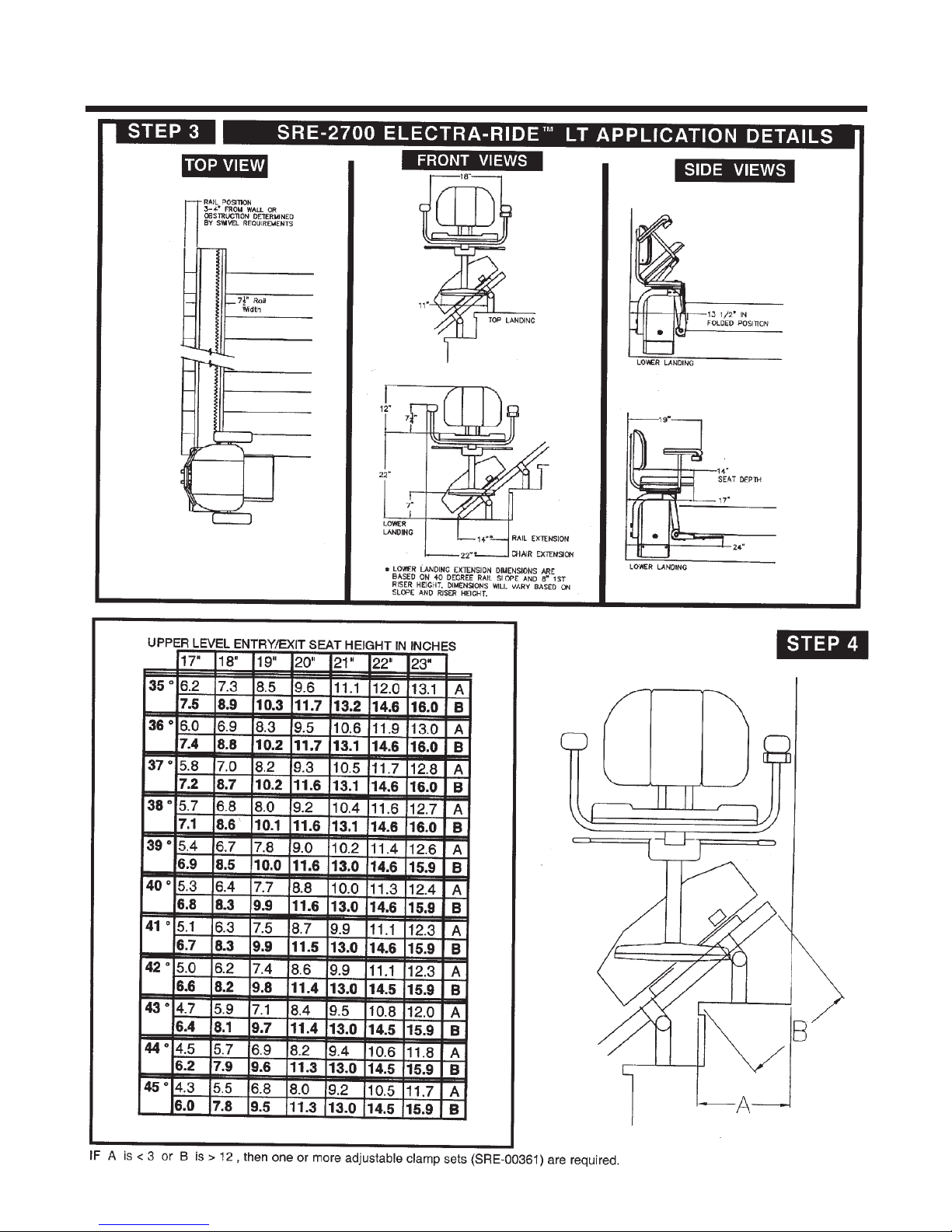
Seat Swivel 0, 45 and 90 degrees at top and bottom
Power Supply 100-240 VAC, 50/60 Hz, 0.85 amp power
supply input, 33 VDC 1-amp transformer
output, 29.6 to 27.6 VDC charging at
850 mA max., continuous monitoring.
SRE-2700 06-11-2004
5
©2004,2002 BRUNO INDEPENDENT LIVING AIDS, INC.®
PACKING LIST
CARTON CONTENTS
The ELECTRA-RIDE™ LT is shipped in 4 cartons. Check the
contents of the cartons to be sure you have all of the components
before beginning an installation.
CHECK CARTON
CONTENTS FOR
SHIPPING DAMAGE
IMMEDIATELY UPON
RECEIPT
*MSDS (Material Safety
Data Sheet) available
from Bruno upon
request. Contact
Service
Department.
Check the carton contents for shipping damage upon receipt.
Damage claims must be filed by the dealer, not the manufacturer.
Bruno Independent Living Aids, Inc.® cannot be responsible for shipping
damage.
CARTON 1
(1) complete carriage assembly including footrest
CARTON 2
(1) complete seat assembly
(2) IR transmitters
Box A
(1) tube
(1)
final limit switch ramp assembly
(1) SRE-K-1553 bumper assembly parts kit
(2) bumper assemblies
(2) pieces of Velcro®
(10) 11" lg wire ties
(1) SRE-K-2705 electrical parts kit (16' rail)
(or SRE-K-2706 for 20' rail)
(1) custom-length charge harness
(2) transmitter mounting brackets
(2) SRE-K-2701 transmitter mounting hardware kit
(1) power supply
(1) SRE-K-1518 power supply hardware kit
Box B
(9) foot clamp sets (16' RAIL) • 11 (20' RAIL)
• TBD** (CUSTOM RAIL)
**DEPENDS UPON RAIL LENGTH
(36) sheet metal screws (M 6.3 X 50 mm)(16' rail);
QTY.44 for (20' rail)
white lithium grease per rail set
***NOTE:
Rail sections must have
matching numbers
stamped on the
sections.
©2004,2002 BRUNO INDEPENDENT LIVING AIDS, INC.®
( ) UPON REQUEST
CARTON 3
(1) rail half (upper)
CARTON 4
(1) rail half (lower)
(1) joint plate
(1) SRE-K-1502 joint plate hardware kit
CARTON 5 (OPTIONAL)
(1) rail half (lower)
(1) joint plate
(1) SRE-K-1502 joint plate hardware kit
6
clamps, adjustable, 9 lbs. ea.
SRE-2700 06-11-2004

INSTALLATION
OVERVIEW
OVERVIEW
OVERVIEW OF INSTALLATION
Installation of the ELECTRA-RIDE™ LT Stairway Elevator consists of the following:
* Determine whether the elevator should be a left- or right-side installation. "Left"
or "right" installation is determined by the side of the stairway on which the rail is
installed (viewed from the bottom of the stairs). THE GEAR RACK WILL BE
TOWARD THE CENTER OF THE STAIRS. Unless specified otherwise, Bruno
Stairway Elevators are set up for left-side installation when shipped, but can easily
be converted to right-side installation. Instructions for converting the unit for
right-hand installation are included later in this manual.
* Identify and locate lower rail section and bumper bracket assembly.
* Assemble and tighten the rail joint. CAUTION: RAILS CANNOT BE MIXED.
CHECK ID NUMBERS STAMPED AT ENDS OF RAILS.
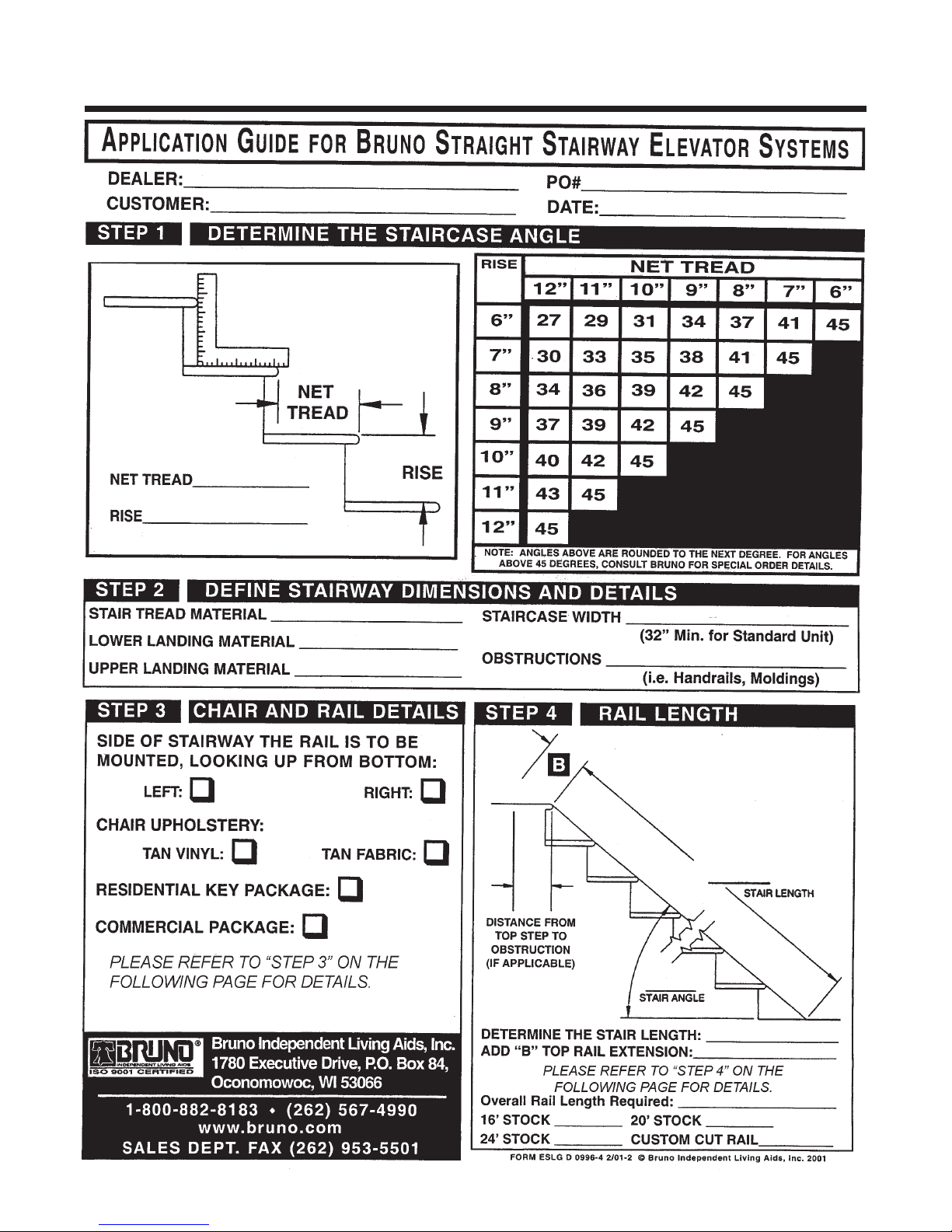
* Determine the correct length for the rail (using Steps 2 & 4 from the APPLICATION
GUIDE), and cut the rail.
* Install lower bumper assembly.
* Position rail on left or right side of stairway using rail clamp assemblies.
* Mount the carriage on the upper rail.
* Adjust the carriage angle by loosening the (2) Angle Adjustment Bolts.
* Install seat assembly and make electrical connections.
* When installing a right-side ELECTRA-RIDE™ LT , follow instructions for
Changing to Right-Hand Operation
* Perform a 5-6 trial runs of the ELECTRA-RIDE™ LT to determine final location of
the rail.
SRE-2700 06-11-2004
7
©2004,2002 BRUNO INDEPENDENT LIVING AIDS, INC.®

INSTALLATION
OVERVIEW
OVERVIEW (CON'T.)
* Determine the appropriate location for the remaining mounting clamps and
brackets for attaching the rail to the stairs then loosely assemble the clamps
and brackets to the Stairway Elevator rail.
* Adjust and tighten the rail clamps and mounting brackets.
* Anchor the mounting brackets to the stairs.
* Locate and drill holes for the top bumper bracket.
* Install the top bumper bracket.
* Determine where the power supply will be positioned, and install rail wire lead
accordingly.
* Position power supply at upper or lower landing.
* Route wire to household outlet.
* Mount remote call/send transmitters.
* Test unit for proper operation.
* Train customer in safe and convenient operation of the Stairway Elevator.
REMEMBER:
No installation is complete until the customer has been trained to use the Elevator
smoothly and safely. After demonstrating correct operation, have the customer
operate the Elevator several times while you are available to answer questions.
BE SURE THE CUSTOMER UNDERSTANDS ALL SAFETY ASPECTS OF
USING THE ELEVATOR. Patience and thoroughness in this phase of the
installation are often rewarded with repeat business and customer referrals.
©2004,2002 BRUNO INDEPENDENT LIVING AIDS, INC.®
8
SRE-2700 06-11-2004
INSTALLATION
Tools Necessary for Installation
[ ] Protractor level, builder's level
[ ] Socket set, metric (10 mm through 22 mm)
[ ] Ratchet, with 6" extension
[ ] Combination wrench set, metric (10 mm through 22 mm)
INSTALLATION
NOTE:
The standard stairway
elevator is suitable for
stairway angles up to
45 degrees.
[ ] Phillips screwdrivers
[ ] 5/16" socket (clamp screws)
[ ] 9/16" and 5/8" open-end wrench (limit switch adjustment)
[ ] 5/16" open-end wrench
[ ] Electric drill with letter `O' (.316") and 1/4" bit
[ ] Hacksaw with 2 or 3 blades, or metal cutting bandsaw
[ ] 20' tape measure
[ ] Small dead blow hammer
[ ] Rubber mallet
[ ] C-clamp
[ ] Wire crimper and stripper
[ ] Flashlight
[ ] Needle nose pliers
[ ] Scissors or knife
TIPS FOR A FASTER, SMOOTHER INSTALLATION:
• Be sure you have all necessary parts and tools before
traveling to installation site.
• Loosely assemble the foot clamp assemblies before
traveling to the installation site.
SRE-2700 06-11-2004
[ ] Extension cord
[ ] Double-sided foam tape
[ ] File
[ ] 12" adjustable wrench
[ ] 90-degree needle-nose pliers
9
©2004,2002 BRUNO INDEPENDENT LIVING AIDS, INC.®
INSTALLATION
INSTALLATION
ASSEMBLY
1) Determine whether a left- or right-side installation is appropriate for the site. "Left" or
"right" refers to the side of the stairway on which the rail is installed (as viewed from the
bottom of the stairs). Unless otherwise specified Bruno Stairway Elevators are shipped
from the factory in the left-side configuration. Conversion to right-side installation is
easy (instructions included later in this manual ).
2) Identify and locate lower rail section appropriate to the installation (left or right).
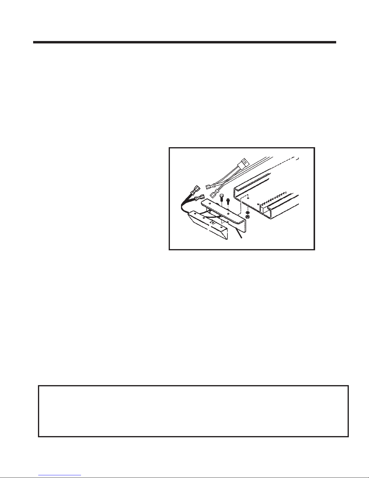
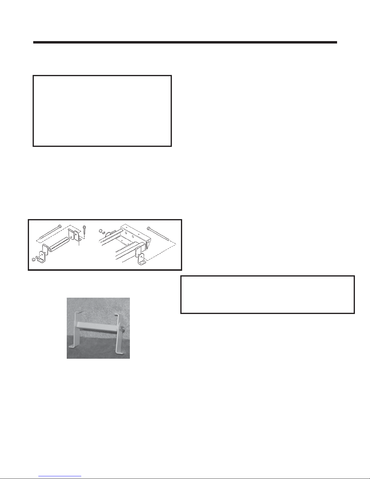
BUMPER BRACKET INSTALLATION
1) Assemble lower rail.
2) Install lower bumper bracket.
bumper bracket
FITTING THE RAIL
1) Determine the correct length for the rail by measuring along a straight line placed on the
stairs. (SEE STEP 2 IN THE APPLICATION GUIDE) To that amount, add Measurement B
(STEP 4 IN THE APPLICATION GUIDE). This process will allow you to custom fit the
Elevator to your customer by determining the most comfortable seat-to-floor height within
the space available at the top of the stairs.
NOTE: The rail must rest approximately 2" above the step nosing, and extend from the lower floor to a
point beyond the nosing of the top step (see Step No. 4 of the Application Guide). In some cases where
the bottom landing is made of material such as concrete, ceramic tile or slate, the last bracket on the
landing may be omitted. In this case, a bracket must be added on the second-to-last step ( bottom), and
at the top of the stairway.
REMINDER:
THIS RAIL MUST BE INSTALLED APPROXIMATELY 2" ABOVE STAIR NOSING.
OTHERWISE, FOOTREST WILL HIT THE STEPS, CAUSING INTERMITTENT
OPERATION.
©2004,2002 BRUNO INDEPENDENT LIVING AIDS, INC.®
10
SRE-2700 06-11-2004
INSTALLATION
SRE-2700 06-11-2004
11
©2004,2002 BRUNO INDEPENDENT LIVING AIDS, INC.®
INSTALLATION
©2004,2002 BRUNO INDEPENDENT LIVING AIDS, INC.®
12
SRE-2700 06-11-2004

INSTALLATION
INSTALLATION
CUTTING THE RAIL
IMPORTANT NOTE!
Under no circumstances should a rail section be cut shorter than
18” (46 cm).
There must be at least (2) clamps on a short rail section (1 at the rail
joint and 1 at the rail end). Cutting a rail shorter than 18” (46 cm)
would not allow enough room for the (2) necessary clamps.
Example:
After measuring the staircase, you determine you need 9 feet of rail.
With your (2) 8-foot sections you decide to use (1) 8-foot section and
cut the remaining (1) foot from the second 8-foot section. Doing this
could yield a rail piece with insufficient weld.
Instead, Bruno recommends cutting at least one foot off one of the
8-foot sections (leaving 7 feet of rail) and then cutting 2 feet from the
second 8-foot section. You will have a (1) 7-foot section and (1) 2-foot
section, both of which are long enough to be properly mounted
(2 clamps minimum per short rail).
NEVER CUT OFF THE JOINT END!
The M6 bolts securing the gear rack must remain intact.
Cut off the end with the pre-drilled charge contact mounting holes.
Then, using the provided template, redrill (2) holes on each end of the rail.
1) Use a metal-cutting power saw or manual
hacksaw to cut the rail to length. Cut off
the end of the rail to be located at the top of the
stairway.
2) Use a file or other appropriate tool to deburr the
cut end of the rail. Soften any sharp edges
which might abrade the insulation of the wiring to
be routed to the bumper at the end of the rail.
use “O” size drill bit
(8.03mm/.316")
SRE-2700 06-11-2004
3) Use a C-clamp to hold the upper bumper bracket in
place at the cut end of the rail. Use the holes in
the bumper bracket as guides to drill mounting
holes in the rail using an“O” size (8.03 mm/.316")
drill bit.
13
©2004,2002 BRUNO INDEPENDENT LIVING AIDS, INC.®
INSTALLATION
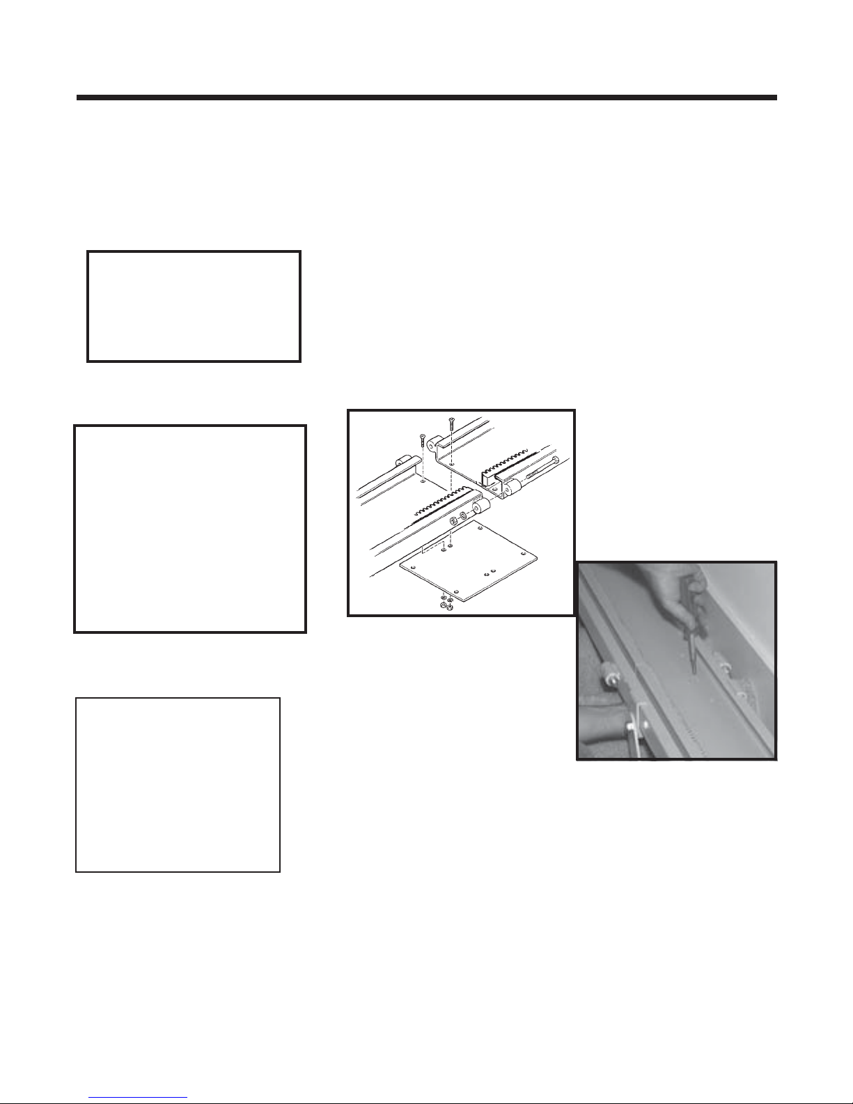
RAIL JOINT ASSEMBLY
NOTE:
The rail is always installed
with the gear rack towards the
center of the stairs and gear
teeth facing the wall.
INSTALLATION
SUGGESTION
1) Assemble the rail joint by attaching the bottom plate to
the rail with the screws, lock washers and hex nuts
provided with the unit. Install the bolts, internal-tooth
washers and hex nuts through the joint blocks on both
sides of the rail. Tighten all bolts securely and make sure
screw heads are flush with the surface of the inside of the
rail. PLEASE REFER TO EXPLODED VIEWS AT
BACK OF MANUAL.
Once two sections of rail
are installed, and before
installing the carriage, run a
plomb line along the rail. If
the rail bows, insert shims
or readjust clamps.
NOTE:
The chamfered
edges of the
holes must face
"up" toward
the bottom of
the rail.
©2004,2002 BRUNO INDEPENDENT LIVING AIDS, INC.®
14
SRE-2700 06-11-2004
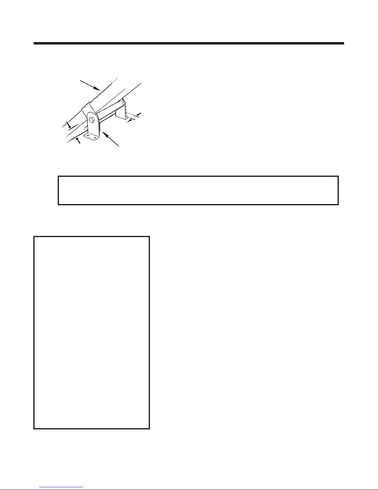
POSITIONING FOOT CLAMP ASSEMBLIES
1) Place rail mounting foot clamps in the
pattern as indicated.
clamp placement order
INSTALLATION
Be sure to leave a minimum space of 4"*,
as measured from the back edge of the
rail to the wall.
•bottom landing
•first tread up from bottom
landing
•top landing
•first tread down from top
landing
•closest tread above and
below the rail joint(s)
•minimum of every third
tread over remainder
of staircase.
*The 4" clearance is needed if the seat is
to swivel 90 degrees. For installations
where the seat will swivel less than
90 degrees, the rail-to-wall clearance
may be reduced to between 3" and
3-1/2". Frequently check the seat-wall
clearance during installation.
Note: If top or bottom clamp is omitted
because the landing is cement or
ceramic tile, or in the event that the
owner wishes not to drill holes in the
landing, a set of clamps should be
added on the second-to-last step and at
the top of stairway.
4" as measured from
back edge of rail to wall.
SRE-2700 06-11-2004
15
©2004,2002 BRUNO INDEPENDENT LIVING AIDS, INC.®
INSTALLATION
INSTALLATION ON CARPET
Before securing the foot clamp
assemblies with hardware, seat them
using a deadblow hammer. Use a
rubber mallet to compress the rug and
pad before anchoring the clamp.
2) For ease of installation, finger tighten all
clamp assemblies to rail. The clamp
assembly should be positioned so the nut
is closest to the wall.
3) Slide top and bottom clamps down on the rail
until firmly seated on step. When installing on
carpeted stairs, use a rubber mallet on the
clamps to compress carpet and pad before
anchoring to steps.
4) Drill in one screw in the foot nearest the wall
of each of the top and bottom of foot of clamp
assemblies.
This will enable the installer to change the
position of the rail if necessary and minimize
the number of holes drilled in the wrong location.
©2004,2002 BRUNO INDEPENDENT LIVING AIDS, INC.®
Bruno recommends installing the screws in the
back clamp (the one closer to the wall) first,
then the screws in the front of the clamp.
16
SRE-2700 06-11-2004
INSTALLATION
INSTALLATION
rail
approx.
2" above
nosing
foot clamp assembly
*Install foot clamps at least 2-1/2” from wall (approx. 4" between the back
edge of the rail and the wall). Provide additional foot clamp-to-wall
clearance if seat needs to swivel against wall.
INSTALLATION NOTES
For installations on hardwood
stairs, Bruno recommends
drilling a pilot hole before
inserting fasteners.
5) Frequently check the measurements at the key
locations indicated to ensure proper positioning
of the clamp assemblies.
*see note below
If threaded fastener
extends below a stair
tread that is exposed, it
can be trimmed flush
with pliers.
Bruno ships the Stairway
Elevator with fasteners
appropriate for
wooden stair treads only.
Other stair material may
require different fasteners.
Please contact Bruno
Independent Living Aids, Inc.
for information.
SRE-2700 06-11-2004
17
©2004,2002 BRUNO INDEPENDENT LIVING AIDS, INC.®
INSTALLATION
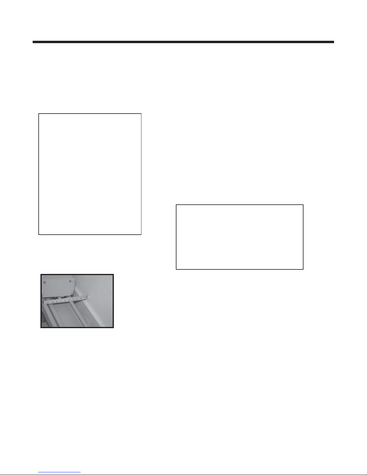
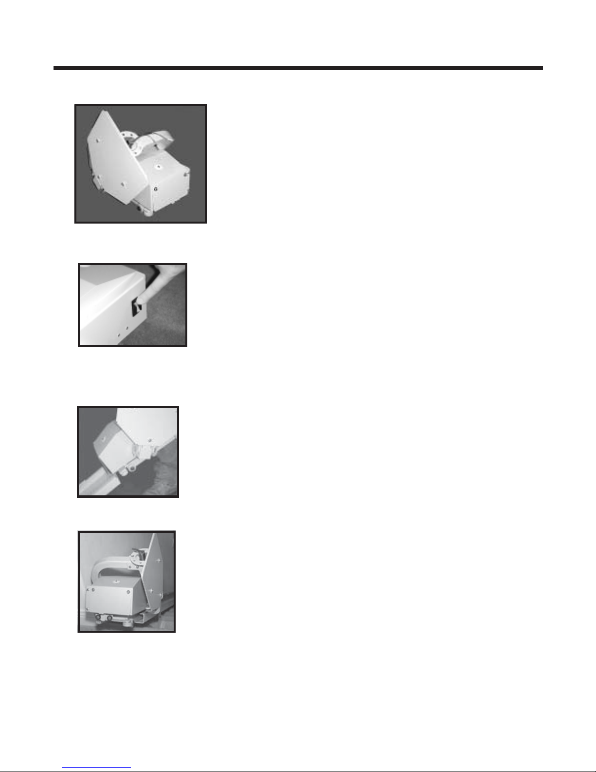
MOUNTING CARRIAGE ON UPPER RAIL
1) Remove the carriage from the shipping carton.
2) Make sure circuit breaker is OFF.
circuit breaker off
sliding carriage on rail
3) Manually slide the carriage onto the rail until
approximately half of the carriage is on the rail.
4) Manually turn the motor pulley to fully engage the
entire carriage onto the rail.
©2004,2002 BRUNO INDEPENDENT LIVING AIDS, INC.®
18
SRE-2700 06-11-2004
 Loading...